

Page 1
PSG1001001CE
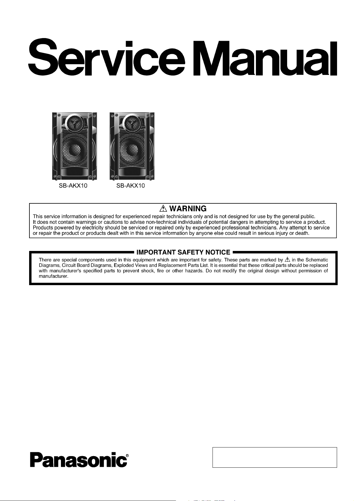
Speaker System
Model No. SB-AKX10PN
Product Color : (K)... Black Type
TABLE OF CONTENTS
1 Service Navigation ----------------------------------------------- 2
1.1. Front Speakers (SB-AKX10PN-K) -------------------- 2
2 Specifications ----------------------------------------------------- 3
3 Disassembly and Assembly Instructions ---------------- 4
3.1. Disassembly of Front Panel Unit ---------------------- 5
3.2. Disassembly of Tweeter Speaker (SP1) ------------- 6
3.3. Disassembly of Full Range Speaker (SP2) --------- 7
3.4. Replacement of Speaker Connector Housing------ 8
4 Wiring Connection Diagram ---------------------------------10
5 Exploded View and Replacement Parts List ----------- 11
5.1. Cabinet Parts Location ---------------------------------11
5.2. Packaging --------------------------------------------------12
5.3. Replacement Parts List ---------------------------------13
PAGE PAGE
© Panasonic Corporation 2010, All rights reserved.
Unauthorized copying and distribution is a violation of
law.
Page 2

1 Service Navigation
1.1. Front Speakers (SB-AKX10PN-K)
The illustrations and disassembly procedures for the Front Speakers will be described in this manual.
2
Page 3

2 Specifications
Front Speakers (SB-AKX10PN-K)
Ty pe 2 way, 2 speaker system (Bass reflex)
Speaker unit(s) Impedance 4 Ω
Full range 16 cm Cone type
Tweeter 6 cm Cone type
Output sound pressure 85 dB/W (1.0 m)
Frequency range 34 Hz to 22 kHz (-16 dB)
41 Hz to 20 kHz (-10 dB)
Dimensions (W x H x D) 220 mm x 332 mm x 186 mm
Mass 2.6 kg
Notes:
1. Specifications are subject to change without notice. Mass and
dimensions are approximate.
2. Total harmonic distortion is measured by the digital spectrum analyzer.
3
Page 4

3 Disassembly and Assembly Instructions
“ATTENTION SERVICER”
Some chassis components may have sharp edges. Be careful when disassembling and servicing.
This section describes procedures for checking the operation and replacing the main components.
For reassembly after operation checks or replacement, reverse the respective procedures.
Special reassembly procedures are described only when required.
Select items from the following index when checks or replacement are required.
Refer to the Parts No. on the page of “Exploded View and Replacement Parts List” (Section 5), if necessary.
Below is the list of disassembly sections
Disassembly of Front Panel Unit
Disassembly of Tweeter Speaker (SP1)
Disassembly of Full Range Speaker (SP2)
4
Page 5
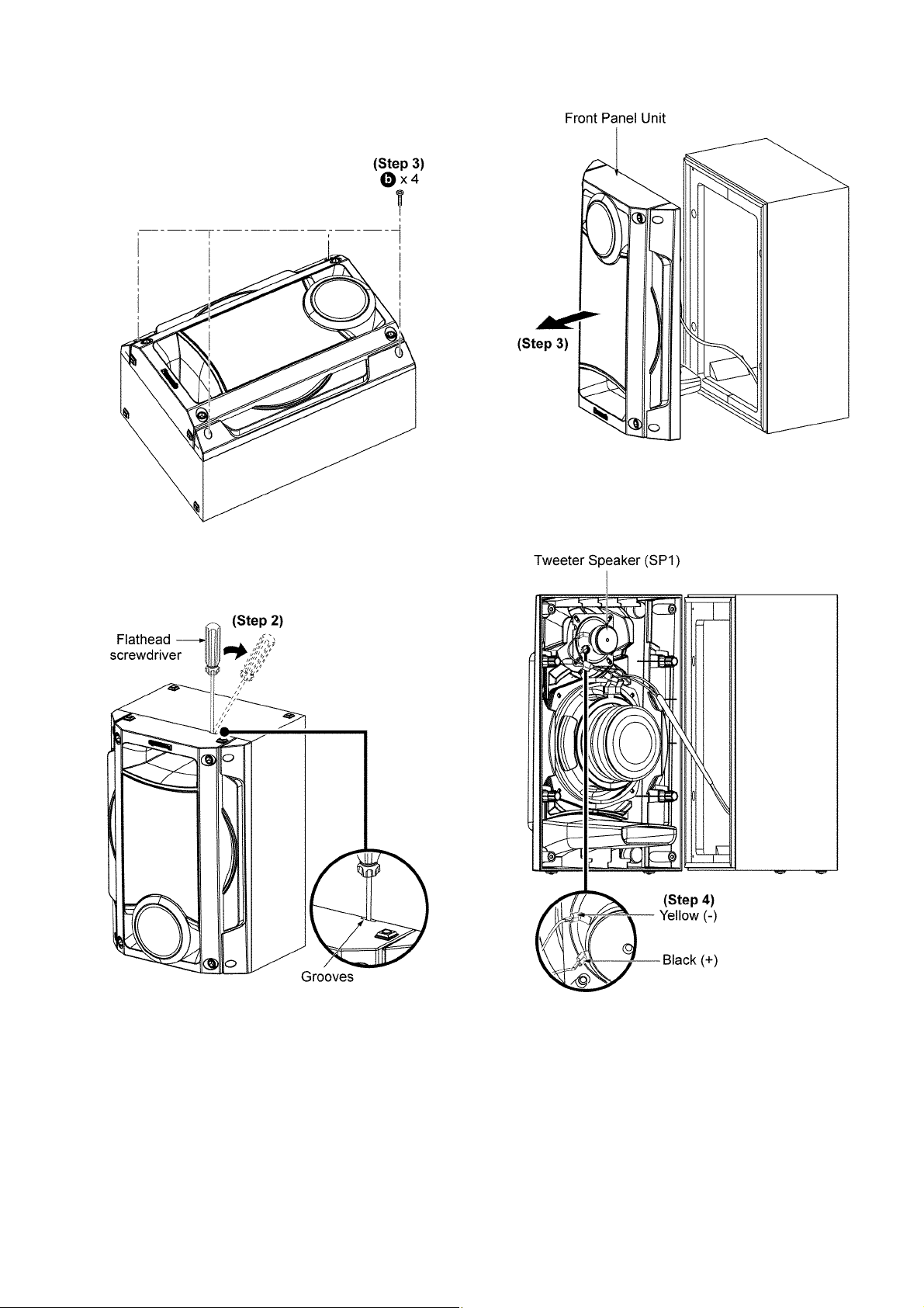
3.1. Disassembly of Front Panel Unit
Step 3: Detach the Front Panel Unit as arrow shown.
Step 1: Remove 4 screws.
Step 2: Insert flathead screwdriver into the grooves and apply
light force to push the Front Panel Unit as arrow shown.
Step 4: Detach the black (+) and yellow (-) speaker wires at the
Tweeter Speaker (SP1).
5
Page 6
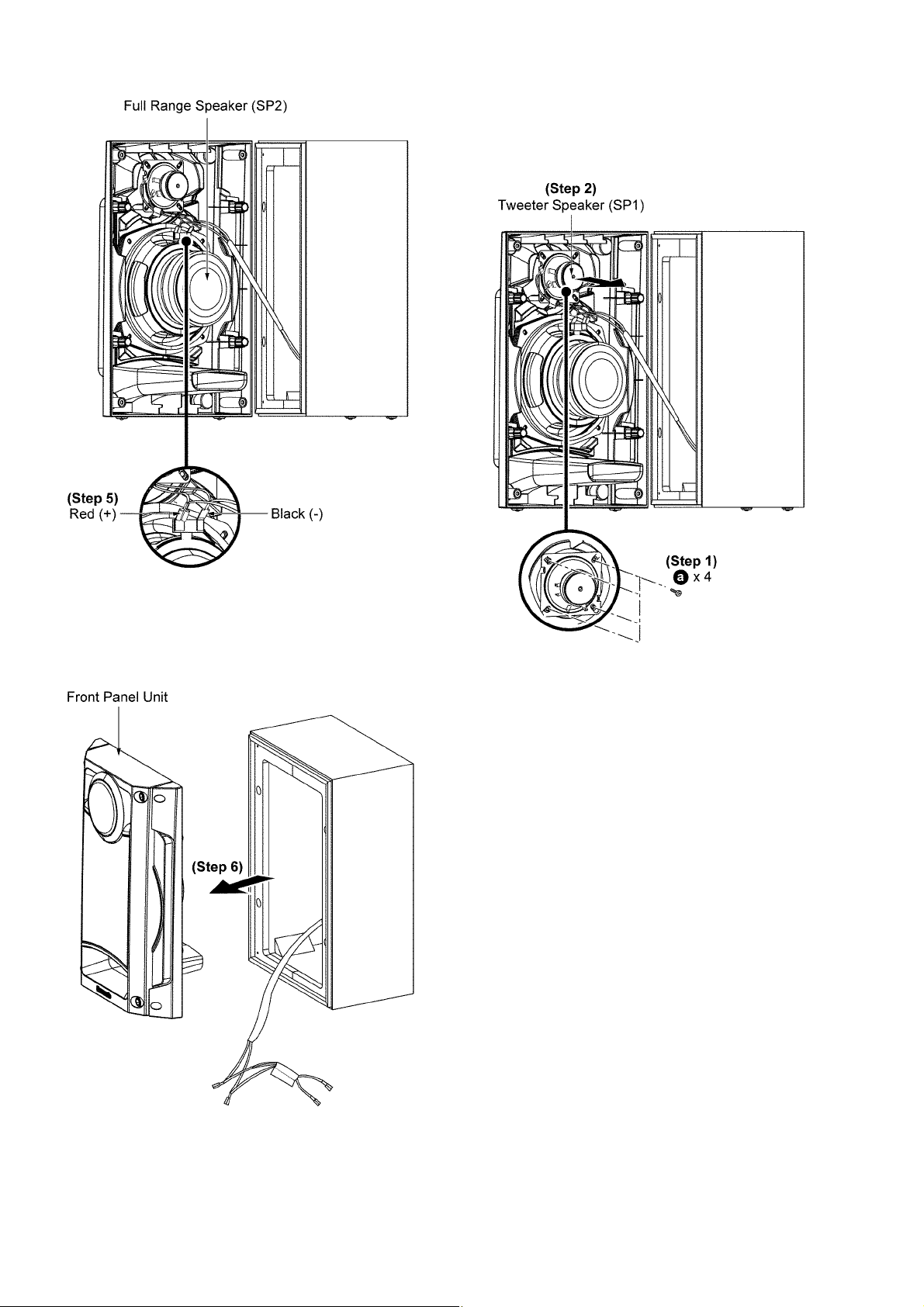
3.2. Disassembly of Tweeter Speaker (SP1)
Follow the (Step 1) to (Step 4) in item 3.1.
Step 5: Detach the red (+) and black (-) speaker wires at the
Full Range speaker (SP2).
Step 1: Remove 4 screws.
Step 2: Remove from Tweeter Speaker (SP1).
Step 6: Remove the Front Panel Unit.
6
Page 7
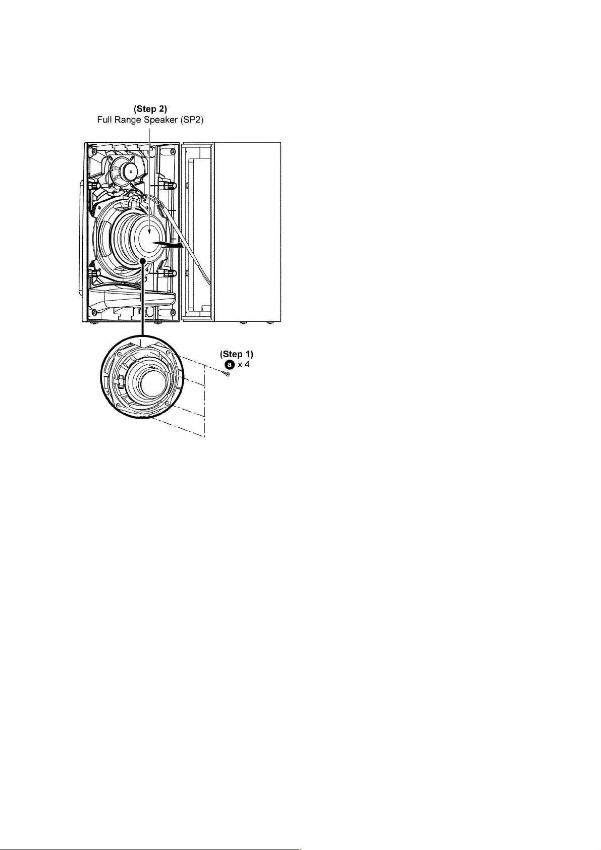
3.3. Disassembly of Full Range Speaker (SP2)
Follow the (Step 1) to (Step 3) in item 3.1.
Follow the (Step 5) in item 3.1.
Step 1: Remove 4 screws.
Step 2: Remove the Full Range Speaker (SP2).
7
Page 8
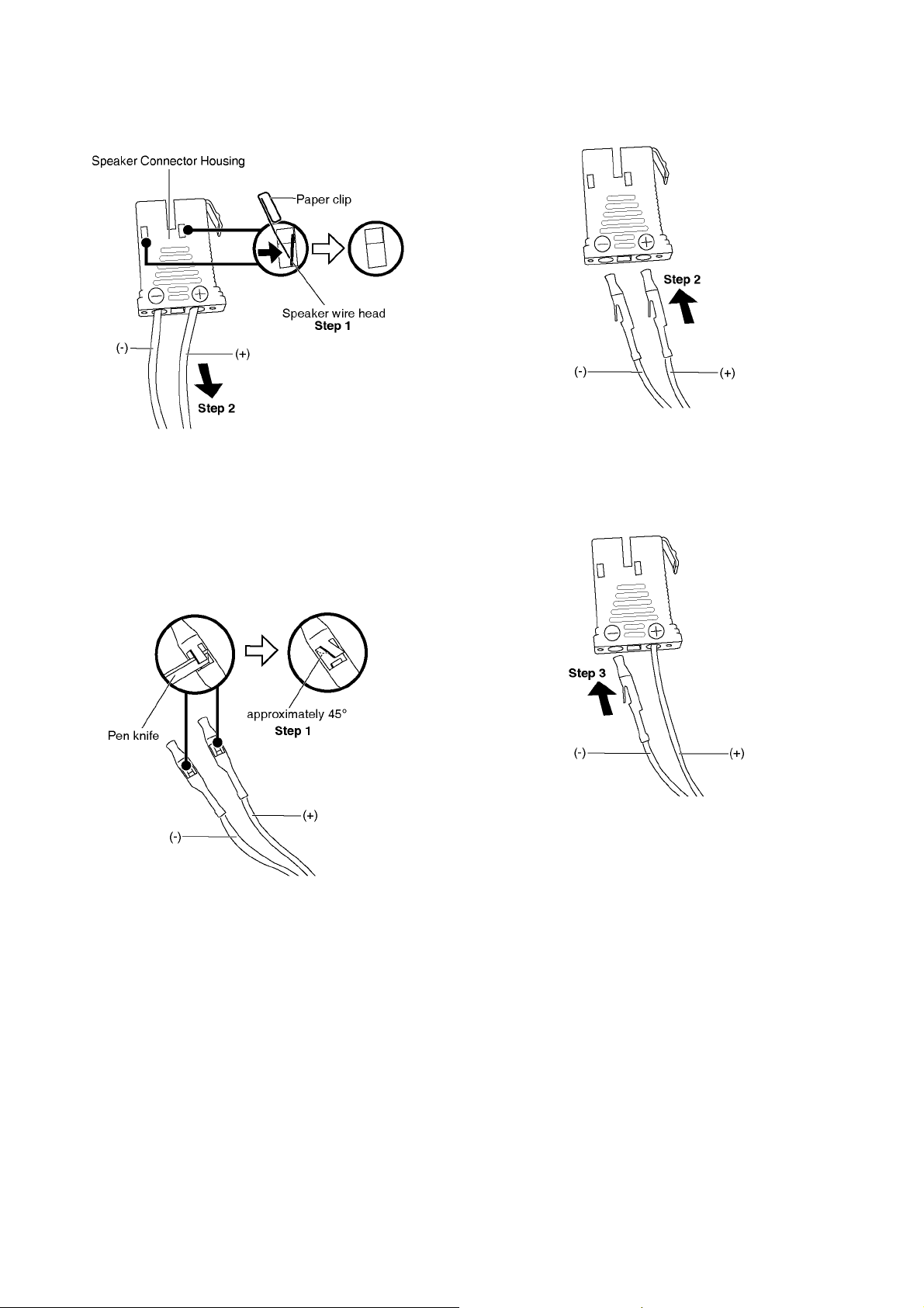
3.4. Replacement of Speaker Connector Housing
3.4.1. Disassembly
Step 1: Use a paper clip push the Speaker Wire head until it
hide inside the Speaker Connector Housing.
Step 2: Pull out the (+) and (-) speaker wire.
3.4.2. Assembly
Cautions: Follow the following procedure during assemble.
Step 2: Insert the (+) speaker wire into the (+) hole of the
Speaker Connector Housing.
Note: Push in the speaker wire until hear the “click” sound.
Step 3: Insert the (-) speaker wire into the (-) hole of the
speaker connector housing.
Note: Push in the speaker wire until hear the “click” sound.
Step 1: Use a pen knife slightly push up the speaker wire head
approximately 45°.
8
Page 9
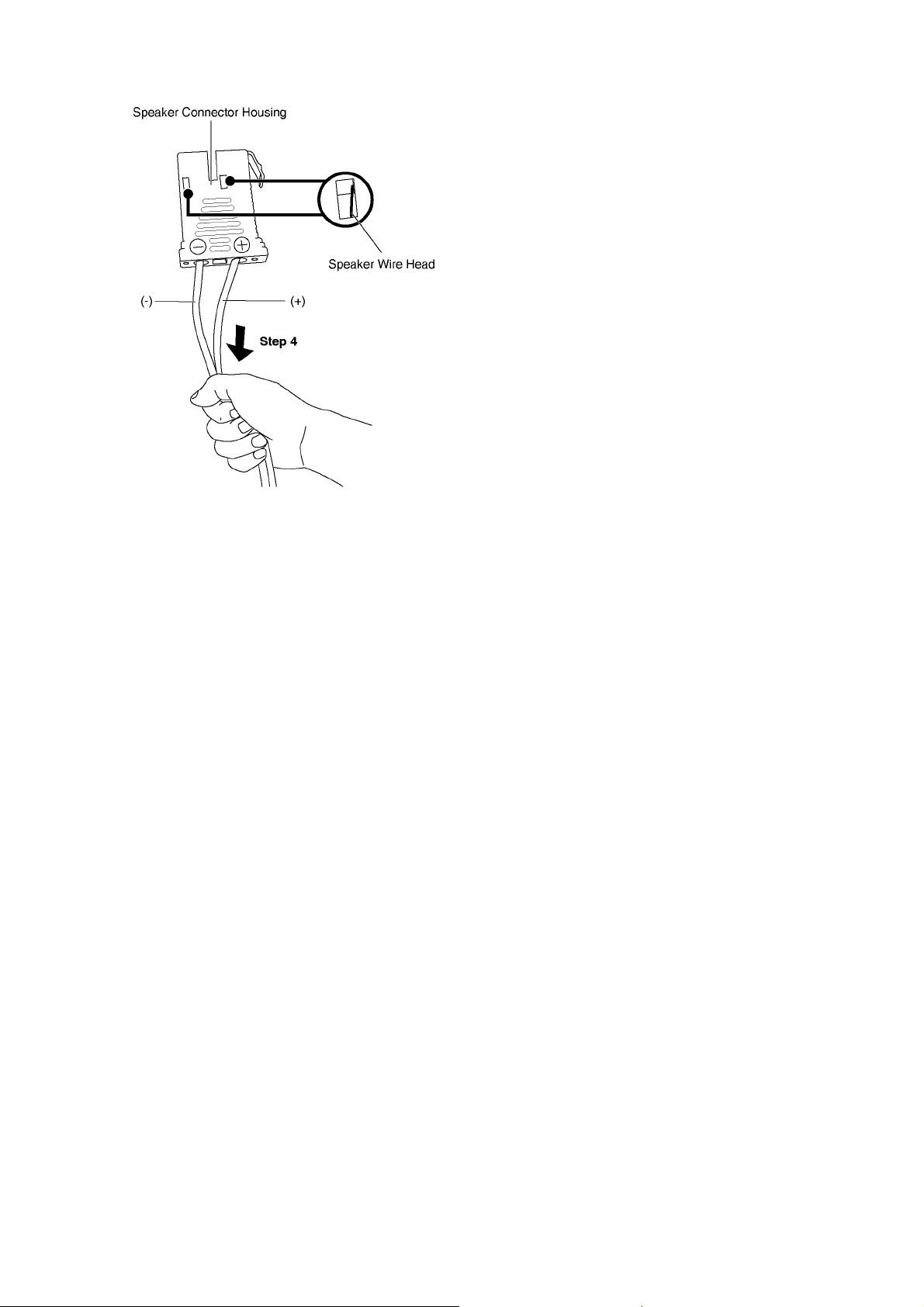
Step 4: Pull both speaker wires gently to ensure they lock-in
firmly.
Note: Repeat step1 to 3 if the speaker wires come out.
9
Page 10
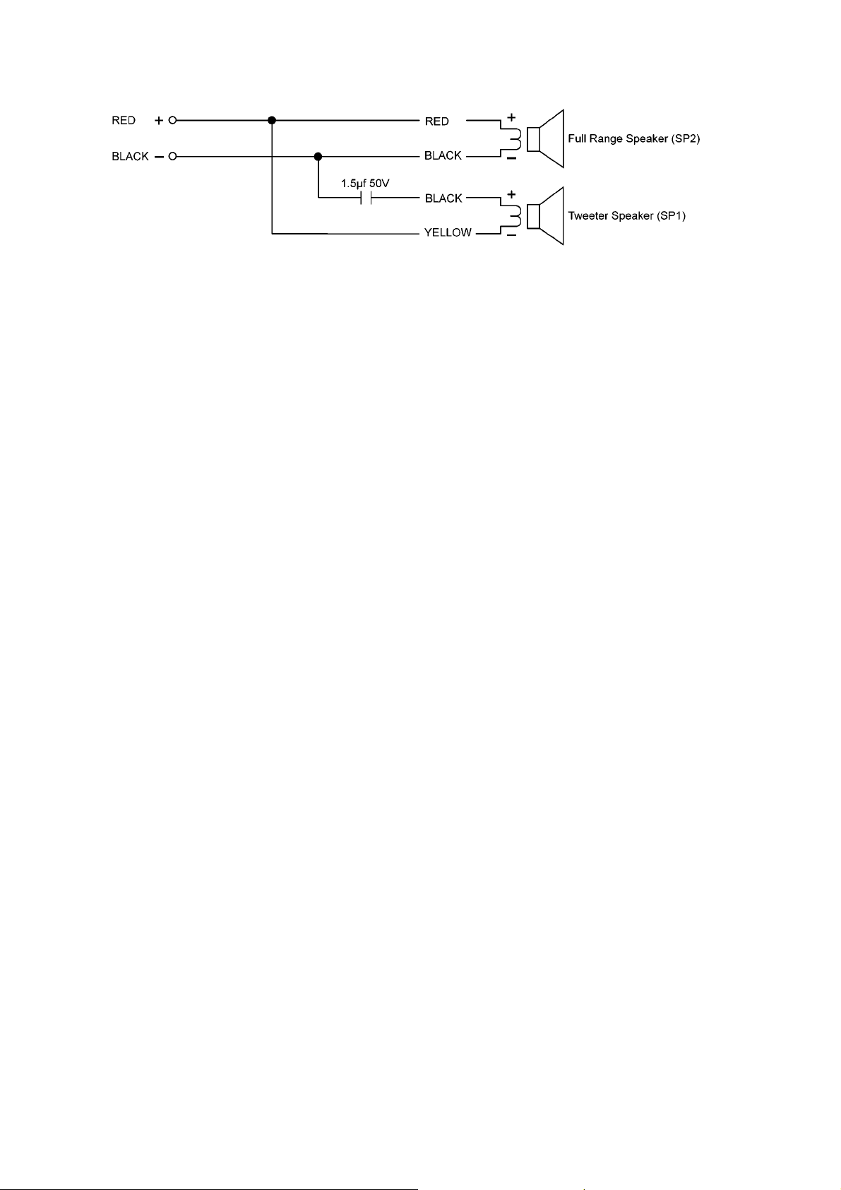
4 Wiring Connection Diagram
10
Page 11
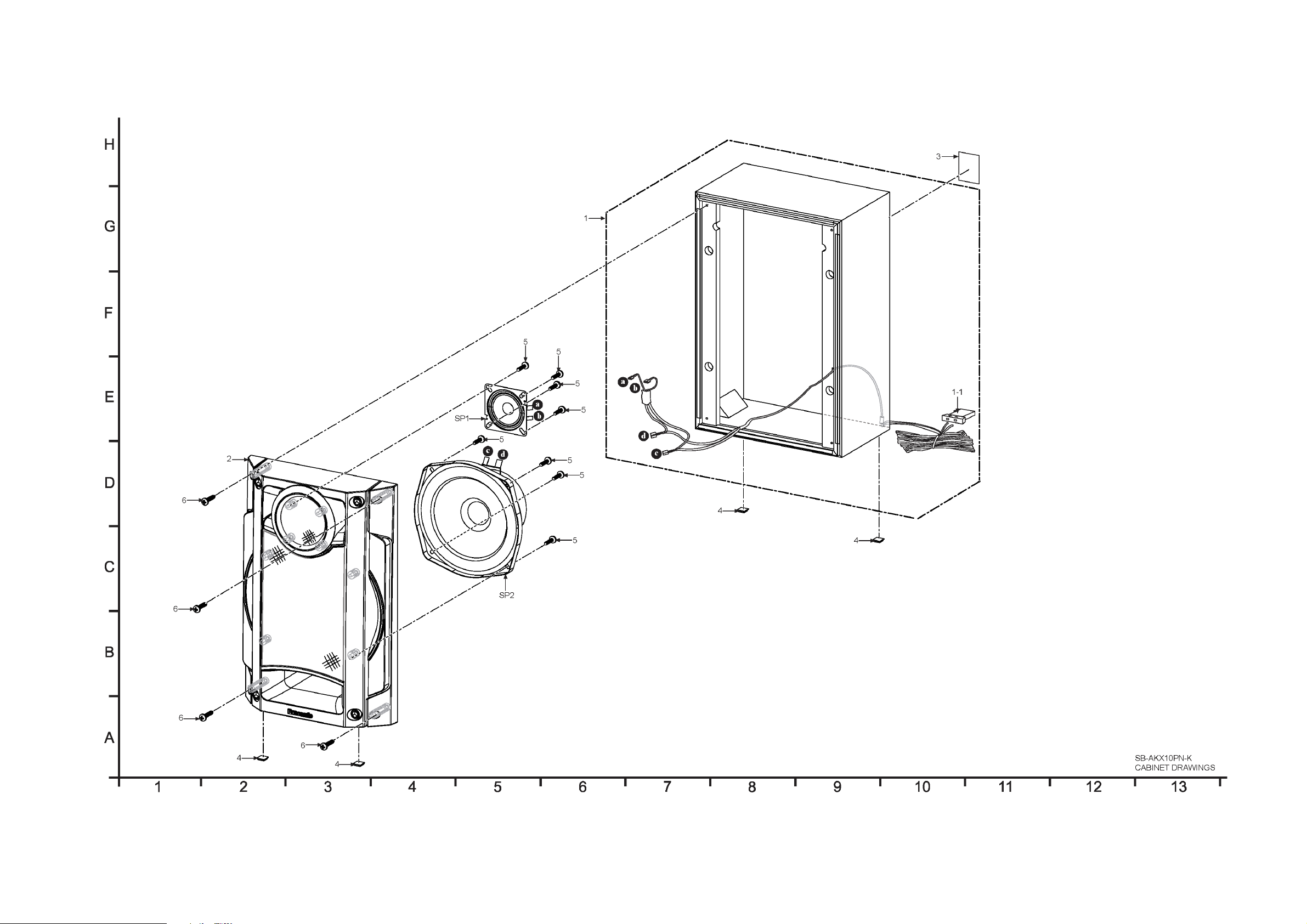
5 Exploded View and Replacement Parts List
5.1. Cabinet Parts Location
11
SB-AKX10PN-K
CABINET DRAWINGS
Page 12
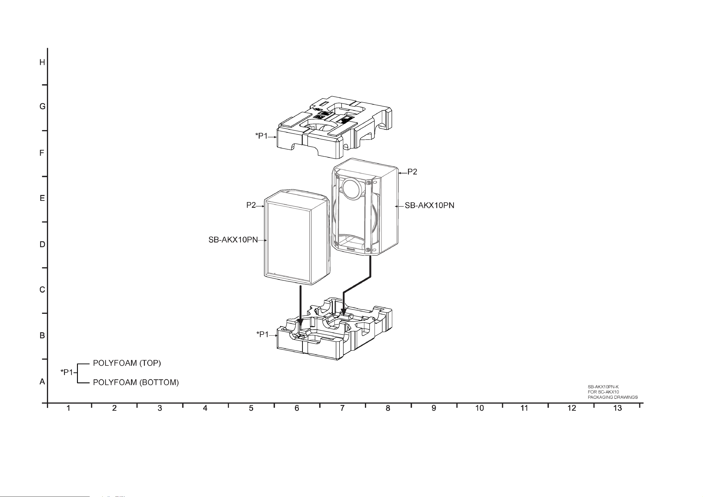
5.2. Packaging
12
SB-AKX10PN-K
FOR SC-AKX10
PACKAGING DRAWINGS
Page 13
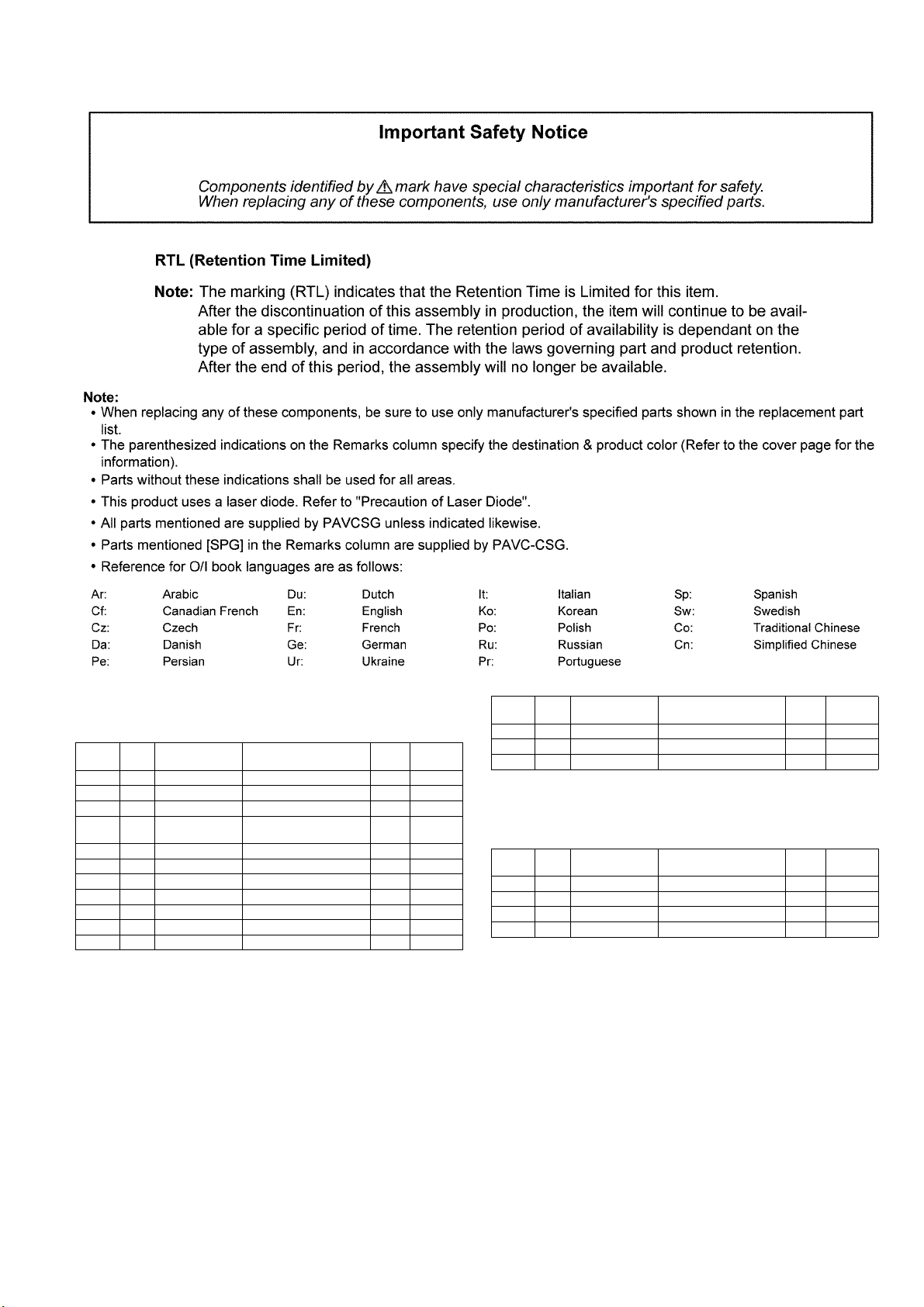
5.3. Replacement Parts List
5.3.1. Front Speakers (SB-AKX10PN-K)
Safety Ref.
1 RYQX1011-K SPEAKER BOX ASS'Y 1
1-1 RFKVBPT760-W SPK CONNECTOR HOUS-
2 RYQX0555A-K1 FRONT PANEL ASS'Y 1
3 RGNX1050-K SPEC LABEL 1
4 RKAX0042-K LEG CUSHION 4
5 XTB4+10GFJ SCREW (SP1,SP2) 8
6 XTB4+16AFJK SCREW 4
Part No. Part Name &
No.
CABINET AND CHASSIS
ING (WHITE)
SPEAKERS
Description
QTY Remarks
1
Safety Ref.
SP1 EAS6PH124J TWEETER SPEAKER 1
SP2 L0AA16A00055 FULL RANGE SPEAKER 1
Part No. Part Name &
No.
Description
QTY Remarks
5.3.2. Accessories and Packing Materials (SB-AKX10PN-K)
Safety Ref.
P1 RPNX1015 POLYFOAM 1
P2 RPFX0233BK MIRAMAT BAG 1
Part No. Part Name &
No.
PACKING MATERIALS
Description
QTY Remarks
FLE1001
13
 Loading...