


SAVK-660-GC
A
r
ORDER NO. MD0707004CE
DVD Stereo System
SA-VK660GC
SA-VK660GS
SA-VK660GCS
SA-VK660GCT
Colour
(K)... Black Type
Notes: This model’s DVD/CD mechanism changer unit is CRS1D. Please refer to the original service
manual (Order No. MD0603065A3) for this mechanism.
Specifications
Q
Q AMPLIFIER SECTION
QQ
RMS Output Power Stereo mode:
Front Channel
115 W per channel (3 Ω), 1 kHz, 10% THD
Subwoofer Channel
115 W per channel (3 Ω), 1 kHz, 10% THD
Total RMS Stereo mode power 345 W
PMPO output power 3700 W
Q
Q FM/AM TUNER, TERMINALS SECTION
QQ
Preset station FM 20 stations
AM 15 stations
Frequency Modulation (FM)
Frequency range 87.50 to 108.00 MHz (50 kHz
step)
Sensitivity 2.5 µV (IHF)
S/N 26dB 1.3 µV
Antenna terminals 75 Ω (unbalanced)
Amplitude Modulation (AM)
Frequency range 522 to 1629 kHz (9 kHz step)
520 to 1630 kHz (10 kHz step)
AM Sensitivity S/N 20dB at 999 kHz
505 µV/m
Digital audio output
Coaxial digital output Pin jack
Music Port Input Jack
Sensitivity 100 mV, 4.7 kΩ
Terminal Stereo, 3.5 mm jack
Phone jack
Terminal Stereo, 3.5 mm jack
Mic jack
Sensitivity 0.7 mV, 600 Ω
Terminal Mono, 6.3 mm jack (2 system)
ux
Sensitivity 2V, 8KΩ
Terminal Stereo, RCA jack
Q
Q CASSETTE DECK SECTION
QQ
Type 1way,Autoreverse
Track system 4 Track, 2 Channel
Heads
Record/playback Solid permalloy head
Erasure Double gap ferrite head
Motor DC servo moto
Recording system AC bias 100 kHz
Erasing system AC erase 100 kHz
Tape speed 4.8 cm/s
Overall frequency response (+3, -6 dB) at DECK OUT
Normal 35 Hz to 14 kHz
S/N ratio 50 dB (A-Weighted)
Wow and flutter 0.18 % (WRMS)
Fast forward and rewind time Approx. 120 seconds with
© 2007 Matsushita Electric Industrial Co. Ltd.. All
rights reserved. Unauthorized copying and
distribution is a violation of law.

A
SA-VK660GC / SA-VK660GS / SA-VK660GCS / SA-VK660GCT
C-60 cassette tape
Q
Q VIDEO SECTION
QQ
Video system PAL625/50, PAL525/60, NTSC
Composite video output
Output level 1 Vp-p (75 Ω)
Terminal Pinjack(1system)
Component video output
[NTSC : 480p/480i, PAL : 576p/576i]
Y output level 1 Vp-p (75 Ω)
PBoutput level 0.7Vp-p(75Ω)
PRoutput level 0.7Vp-p(75Ω)
Terminal
Pin jack (Y: green, PB:blue,PR:red)(1system)
Q
Q DISC SECTION
QQ
Disc played [8 cm or 12 cm]
(1) DVD (DVD-Video, DivX
(2) DVD-RAM (DVD-VR, JPEG
(3) DVD-R (DVD-Video, DVD-VR, JPEG
*6,*7
DivX
)
*6,*7
)
*4,*7
,MP3
*2,*7
*4,*7
, MPEG4
*2,*7
,MP3
*5,*7
, DivX
, MPEG4
*6,*7
*5,*7
)
,
(4) DVD-R DL (DVD-Video, DVD-VR)
(5) DVD-RW (DVD-Video, DVD-VR, JPEG
*6,*7
DivX
)
*4,*7
,MP3
*2,*7
, MPEG4
*5,*7
(6) +R/ +RW (Video)
(7) +R DL (Video)
(8) CD,CD-R/RW [CD-DA, Video CD, SVCD*1,MP3
JPEG
*4,*7
, MPEG4
*5,*7
, DivX
*6,*7
, HighMAT Level 2 (Audio and
*2,*7
,WMA
*3,*7
,
Image)]
*1
Conforming to IEC62107
*2
MPEG-1 Layer 3, MPEG-2 Layer 3
*3
Windows Media Audio Ver 9.0 L3
Not compatible with Multiple Bit Rate (MBR)
*4
Exif Ver 2.1 JPEG Baseline files
Picture resolution: between 160 x 120 and 6144 x 4096 pixels (Sub
sampling is 4:0:0, 4:2:0, 4:2:2 or 4:4:4). Extremely long and narrow
pictures may not be displayed.
*5
MPEG4 data recorded with the Panasonic SD multi cameras or
DVD video recorders. Conforming to SD VIDEO specifications (ASF
standard)/ MPEG4 (Simple Profile) video system/ G.726 audio
system.
*6
Plays all versions of DivX®video (including DivX®6) with standard
playback of DivX
®
media files. Certified to the DixV®Home Theater
Profile. GMC (Global Motion Compensation) is not supported.
*7
The total combined maximum number of recognizable audio,
picture and video contents and groups: 4000 audio, picture and video
contents and 400 groups.
Pick up
Wavelength
CD 785 nm
DVD 662 nm
Laser Power
CD CLASS 1M
DVD CLASS 1
Audio output (Disc)
Number of channels (FL, FR) 2 channel
Q
Q GENERAL
QQ
Power supply
For GC only AC 220 V to 240 V, 50/60 Hz
For GS/GCS/GCT only
C 110 V to 127 V/220 V to 240 V, 50/60 Hz
Power consumption 125 W
Power consumption in standby mode:
0.9 W (approx.)
Dimensions (W x H x D) 250 mm x 330 mm x 333.6 mm
Mass 7.5 kg
Operating temperature range +5°C to +35°C
Operating humidity range 5% to 90% RH (no condensation)
Q
Q SYSTEM
QQ
SC-VK660(GC) Music Center: SA-VK660 (GC)
Speaker: SB-PF660 (GC)
Subwoofer: SB-WVK660 (GC)
SC-VK660(GS) Music Center: SA-VK660 (GS)
Speaker: SB-PF660 (GC)
Subwoofer: SB-WVK660 (GC)
SC-VK660(GCS) Music Center: SA-VK660 (GCS)
Speaker: SB-PF660 (GC)
Subwoofer: SB-WVK660 (GC)
,
SC-VK660(GCT) Music Center: SA-VK660 (GCT)
Speaker: SB-PF660 (GC)
Subwoofer: SB-WVK660 (GC)
For information on speaker system, please refer to the original
Service Manual (Order No. MD0707005CE) for SB-PF660GC-K and
Service Manual (Order No. MD0707006CE) for SB-WVK660GC-K.
Notes:
1. Specifications are subject to changes without notice. Mass and
dimensions are approximate.
2. Total harmonic distortion is measured by the digital spectrum
analyzer.
2
SA-VK660GC / SA-VK660GS / SA-VK660GCS / SA-VK660GCT
CONTENTS
Page Page
1 Safety Precautions 6
1.1. General Guidelines
6
1.2. Safety Precaution for AC Power Supply Cord (For GS
only) 7
1.3. Before Use (For GS/GCS/GCT only)
3
7

SA-VK660GC / SA-VK660GS / SA-VK660GCS / SA-VK660GCT
1.4. Before Repair and Adjustment 7
1.5. Protection Circuitry
1.6. Safety Parts Information
2 Prevention of Electrostatic Discharge (ESD) to
Electrostatically Sensitive (ES) Devices
3 Precaution of Laser Diode
4 About Lead-Free Solder (PbF)
4.1. Service caution based on legal restrictions
5 Handling Precautions for Traverse Unit
5.1. Handling Optical Pickup
5.2. Replacing Precautions for Optical Pickup Unit
5.3. Grounding for Preventing Electrostatic Destruction
6 Accessories
7 Operation Procedures
7.1. Main Unit Operation Control
7.2. Remote Control Operation Control
7.3. Disc Information
7.4. DivX VOD Content
8 DVD/CD Mechanism Changer Unit
8.1. CRS1D Mechanism Overview
8.2. Music Port
9 Self diagnosis and special mode setting
9.1. Service Mode Summary Table
9.2. Service Mode Table
9.3. Optical Pick-up Breakdown Diagnosis
9.4. DVD Self-Diagnostic Function Error Code
9.5. Sales Demostration Lock Function
9.6. Service Precautions
10 Assem bling and Disassembl in g
10.1. Caution
10.2. Disassembly flow chart
10.3. Main Parts Location
10.4. Disassembly of Top Cabinet
10.5. Disassembly of DVD/CD Mechanism Changer Unit
10.6. Disassembly of Rear Panel
10.7. Disassembly of Main P.C.B.
10.8. Disassembly of SMPS P.C.B.
10.9. Disassembly of D-Amp P.C.B.
10.10. Disassembly of Front Panel Unit
10.11. Disassembly for Mic P.C.B.
10.12. Disassembly for Panel P.C.B.
10.13. Disassembly of Tact Switch P.C.B.
10.14. Disassembly of Deck mechanism unit
10.15. Disassembly of Deck P.C.B.
10.16. Disassembly for Deck Mechanism
10.17. Disassembly of Traverse Unit
10.18. Disassembly of DVD Module P.C.B.
10.19. Disassembly of Deck Mechanism P.C.B.
10.20. Replacement for cassette lid
10.21. Rectification for tape jam problem
11 Service Positi ons
11.1. Checking and Repairing of Main P.C.B.
11.2. Checking and Repairing of SMPS P.C.B.
11.3. Checking and Repairing of Panel P.C.B.
11.4. Checking and Repairing of D-Amp P.C.B., Deck P.C.B. &
7
8
12 Adjustment Procedures
Deck Mechanism P.C.B.
12.1. Cassette Deck Section
8
9
10
10
11
11
11
11
12
13
13
14
15
17
18
18
21
22
22
22
32
34
40
40
42
42
44
45
45
46
47
47
48
48
49
50
50
51
52
52
52
55
57
57
57
57
59
59
59
60
12.2. Tuner Section
12.3. Alignment Points
13 Illustration of ICs, Transistors and Diodes
14 Vol tage and Waveform Chart
14.1. DVD Module P.C.B.
14.2. Main P.C.B.
14.3. Panel P.C.B.
14.4. Damp P.C.B. & SMPS P.C.B.
14.5. Deck P.C.B., Deck Mechanism P.C.B. & Mic P.C.B.
14.6. Waveform Chart
15 Wiring Connection Diagra m
16 Block Diagra m
16.1. System Control Block Diagram
16.2. DVD Servo/ Video Block Diagram
16.3. Audio Block Diagram
16.4. Digital Amp Block Diagram
16.5. Deck Block Diagram
16.6. SMPS Block Diagram
17 Schem atic Diagra m Notes
18 Schematic Diagram
18.1. (A) DVD Module Circuit
18.2. (B) Main Circuit
18.3. (C) Panel Circuit
18.4. (D) Tact Switch Circuit, (E) Mic Circuit & (G) Deck
Mechanism Circuit
18.5. (F) Deck Circuit
18.6. (H) D-Amp Circuit
18.7. (I) SMPS Circuit
18.8. Optical Pickup Unit Circuit
19 Prin ted Ci rcui t Board
19.1. (A) DVD Module P.C.B. (Side A & B )
19.2. (B) Main P.C.B.
19.3. (C) Panel P.C.B.
19.4. (D) Tact Switch P.C.B., (E) Mic P.C.B., (F) Deck P.C.B. &
(G) Deck Mechanism P.C.B.
19.5. (H) D-Amp P.C.B.
19.6. (I) SMPS P.C.B. (For GC Only)
19.7. (I) SMPS P.C.B. (For GCS/GS/GCT Only)
20 Basic Troubleshooting Guide for Backe nd Module
20.1. Initialisation and Playability
21 Terminal Function of IC
108
21.1. IC2801 (C2CBYY000468
21.2. IC6601 (C0HBB0000057
22 Expl od ed View s
22.1. Cabinet Parts Location
22.2. Deck Mechanism Unit Parts Location (RAA4901-S)
22.3. Packaging
61
62
62
63
64
65
66
66
67
68
68
69
70
71
73
73
74
75
76
77
78
79
81
81
85
89
91
92
93
95
97
99
100
101
102
103
104
105
106
107
107
) System Microprocessor
108
)FLDriverIC
109
111
111
113
114
4

SA-VK660GC / SA-VK660GS / SA-VK660GCS / SA-VK660GCT
23 Repl acement Parts List 115
23.1. Component Parts List
116
24 Schem atic Diagra m for printing w ith letter size
129
5
SA-VK660GC / SA-VK660GS / SA-VK660GCS / SA-VK660GCT
1 Safety Precautions
1.1. General Guidelines
1. When servicing, observe the original lead dress. If a short circuit is found, replace all parts which have been overheated or
damaged by the short circuit.
2. After servicing, see to it that all the protective devices such as insulation barriers, insulation papers shields are properly
installed.
3. After servicing, make the following leakage current checks to prevent the customer from being exposed to shock hazards.
1.1.1. Leakage Current Cold Check
1. Unplug the AC cord and connect a jumper between the two prongs on the plug.
2. Measure the resistance value, with an ohmmeter, between the jumpered AC plug and each exposed metallic cabinet part on
the equipment such as screwheads, connectors, control shafts, etc. When the exposed metallic part has a return path to the
chassis, the reading should be between 1MΩ and 5.2MΩ.
When the exposed metal does not have a return path to the chassis, the reading must be
.
Figure 1
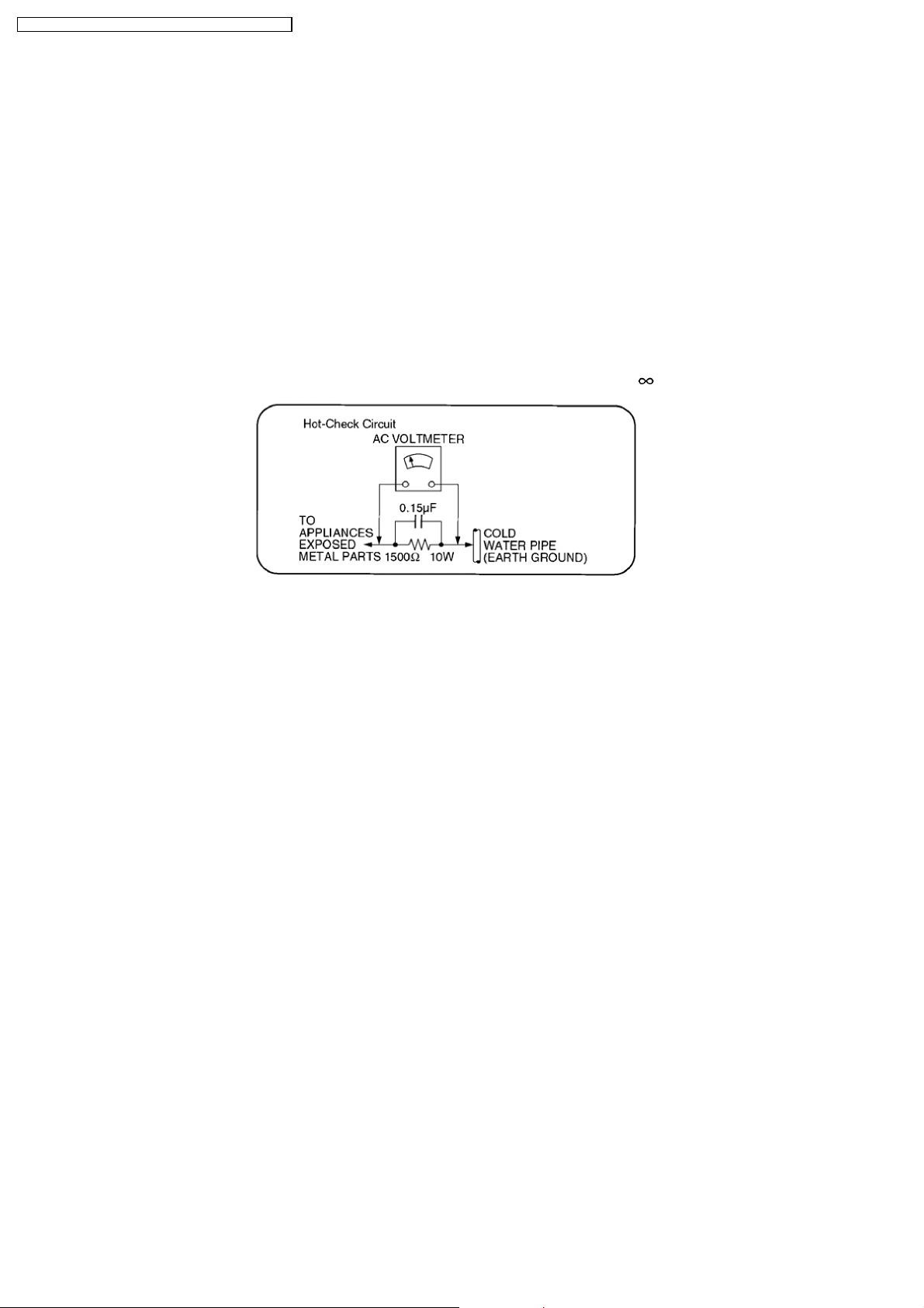
1.1.2. Leakage Current Hot Check
1. Plug the AC cord directly into the AC outlet. Do not use an isolation transformer for this check.
2. Connect a 1.5kΩ, 10 watts resistor, in parallel with a 0.15µF capacitor, between each exposed metallic part on the set and a
good earth ground such as a water pipe, as shown in Figure 1.
3. Use an AC voltmeter, with 1000 ohms/volt or more sensitivity, to measure the potential across the resistor.
4. Check each exposed metallic part, and measure the voltage at each point.
5. Reverse the AC plug in the AC outlet and repeat each of the above measurements.
6. The potential at any point should not exceed 0.75 volts RMS. A leakage current tester (Simpson Model 229 or equivalent) may
be used to make the hot checks, leakage current must not exceed 1/2 milliamp. In case a measurement is out of the limits
specified, there is a possibility of a shock hazard, and the equipment should be repaired and rechecked before it is returned to
the customer.
6
SA-VK660GC / SA-VK660GS / SA-VK660GCS / SA-VK660GCT
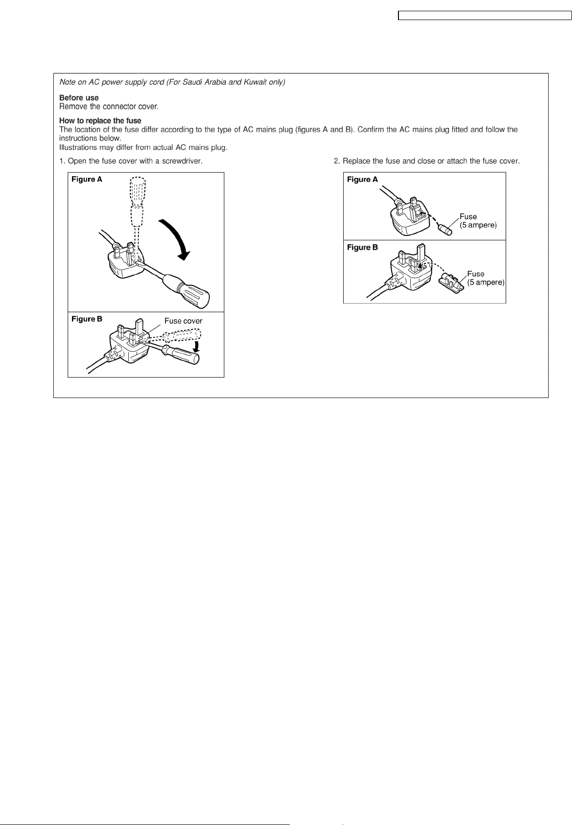
1.2. Safety Precaution for AC Power Supply Cord (For GS only)
1.3. Before Use (For GS/GCS/GCT only)
Be sure to disconnect the mains cord before adjusting the voltage selector.
Use a minus(-) screwdriver to set the voltage selector (on the rear panel) to the voltage setting for the area in which the unit will
be used. (If the power supply in your area is 117V or 120V, set to the “117V or 120V” position.)
Note that this unit will be seriously damaged if this setting is not made correctly. (There is no voltage selector for some countries,
the correct voltage is already set.)
1.4. Before Repair and Adjustment
Disconnect AC power, discharge Power Supply Capacitors C2550, C2556, C5101, C5104, C5165, C5166, C5171, C5172, C5950
and C5966 through a 10Ω, 1W resistor to ground.
DO NOT SHORT-CIRCUIT DIRECTLY (with a screwdriver blade, for instance), as this may destroy solid state devices.
After repairs are completed, restore power gradually using a variac, to avoid overcurrent.
Current consumption at AC 220~240V, 50/60 Hz in NO SIGNAL (vol. min, at CD mode) should be ~250mA . [For GC only]
Current consumption at AC 110~127V, 50/60 Hz & AC 220~240V, 50/60Hz in NO SIGNAL (vol. min, at CD mode) should be
~400mA and ~250mA respectively. [For GCS/GS/GCT only]
1.5. Protection Circuitry
The protection circuitry may have operated if either of the following conditions are noticed:
•
• No sound is heard when the power is turned on.
• •
•
• Sound stops during a performance.
• •
The function of this circuitry is to prevent circuitry damage if, for example, the positive and negative speaker connection wires are
“shorted”, or if speaker systems with an impedance less than the indicated r ated impedance of the amplifier are used.
If this occurs, follow the procedure outlines below:
1. Turn off the power.
2. Determine the cause of the problem and correct it.
3. Turn on the power once again after one minute.
7
SA-VK660GC / SA-VK660GS / SA-VK660GCS / SA-VK660GCT
Note :
When the protection circuitry functions, the unit will not operate unless the power is first turned off and then on again.
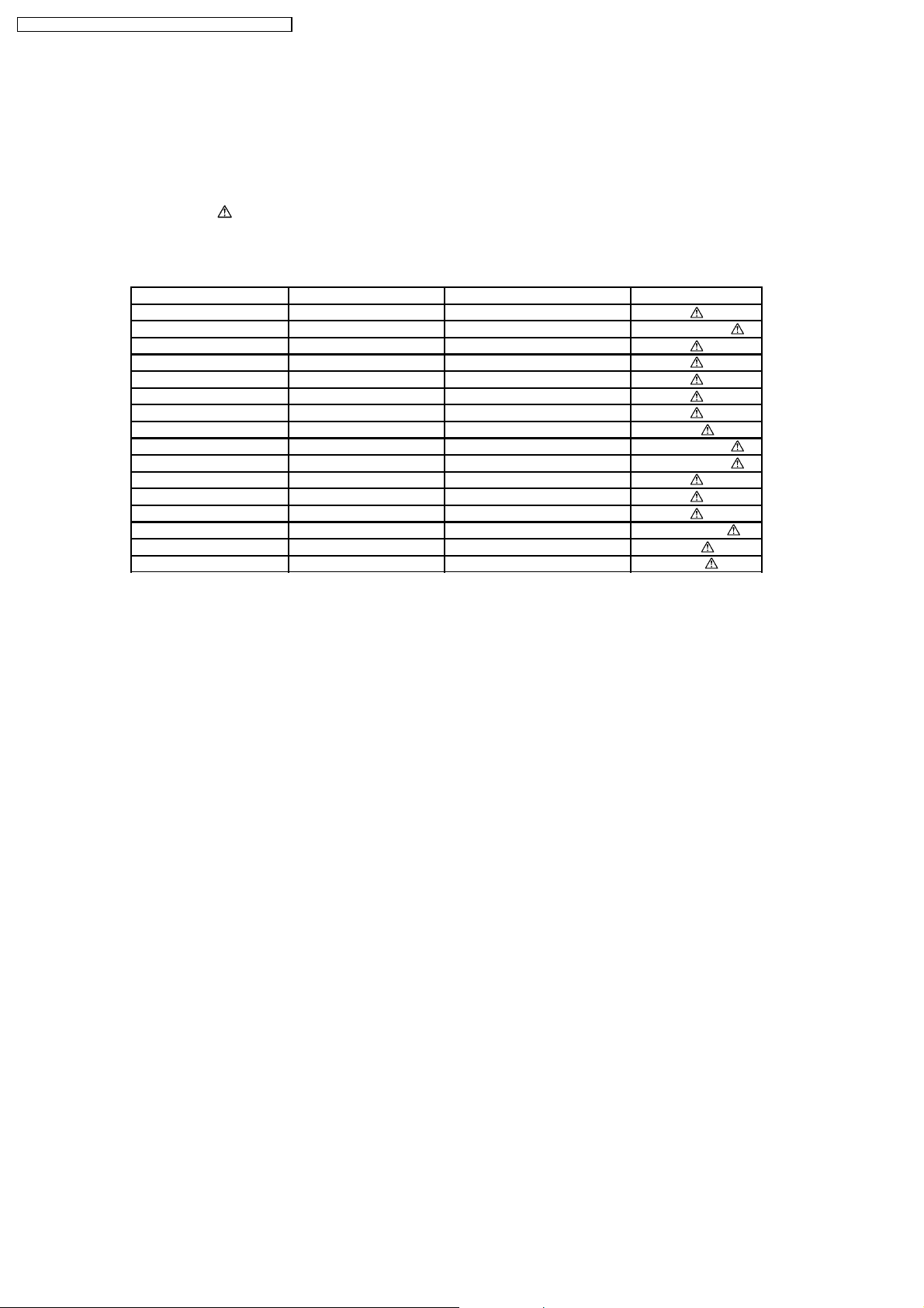
1.6. Safety Parts Information
Safety Parts List:
There are special components used in this equipment which are important for safety.
These parts are marked by
be replaced with manufacturer’s specified parts to prevent shock, fire or other hazards. Do not modify the original design without
permission of manufacturer.
Table 1
Reference No. Part No. Part name & Description Remarks
RL5950 K6B1AEA00015 POWER RELAY
FP5100 K5G401A00008 FUSE PROTECTOR
FP5950 K5G402A00025 FUSE PROTECTOR
JK5950 K2AA2B000011 JK AC INLET
in the Schematic Diagrams & Replacement Parts List. It is essential that these critical parts should
360 RAE2023Z-S TRAVERSE UNIT
S5950 K0ABLB000003 SW VOLTAGE SELECTOR GS/GCS/GCT
L5950 ELF15N035AN LINE FILTER
T5950 G4CYBYY00013 MAIN TRANSFORMER
T5951 G4C2AAJ00005 SUB TRANSFORMER
Z5950 ERZV10V511CS ZENER
F1 K5D122BLA014 FUSE GC
F1 K5D252BLA013 FUSE GS/GCS/GCT
F2 K5D122BLA014 FUSE GS/GCS/GCT
A2 K2CQ2CA00007 AC CORD GC/GCS/GS
A2 K2CT3CA00004 AC CORD GS
A2 K2CP2YY00001 AC CORD GCT
2 Prevention of Electrostatic Discharge (ESD) to
Electrostatically Sensitive (ES) Devices
Some semiconductor (solid state) devices can be damaged easily by electricity. Such components commonly are called
Electrostatically Sensitive (ES) Devices. Examples of typical ES devices are integrated circuits and some field-effect transistors and
semiconductor “chip” components. The following techniques should be used to help reduce the incidence of component damage
caused by electrostatic discharge (ESD).
1. Immediately before handling any semiconductor component or semiconductor-equipped assembly, drain off any ESD on your
body by touching a known earth ground. Alternatively, obtain and wear a commercially available discharging ESD wrist strap,
which should be removed for potential shock reasons prior to applying power to the unit under test.
2. After removing an electrical assembly equipped with ES devices, place the assembly on a conductive surface such as
aluminium foil, to prevent electrostatic charge build up or exposure of the assembly.
3. Use only a grounded-tip soldering iron to solder or unsolder ES devices.
4. Use only an anti-static solder remover device. Some solder removal devices not classified as “anti-static (ESD protected)” can
generate electrical charge to damage ES devices.
5. Do not use freon-propelled chemicals. These can generate electrical charges sufficient to damage ES devices.
6. Do not remove a replacement ES device from its protective package until immediately before you are ready to install it. (Most
replacement ES devices are packaged with leads electrically shorted together by conductive foam, aluminium foil or
comparable conductive material).
7. Immediately before removing the protective material from the leads of a replacement ES device, touch the protective material
to the chassis or circuit assembly into which the device will be installed.
Caution
Be sure no power is applied to the chassis or circuit, and observe all other safety precautions.
8. Minimize body motions when handling unpackaged replacement ES devices. (Otherwise harmless motion such as the brushing
together of your clothes fabric or the lifting of your foot from a carpeted floor can generate static electricity (ESD) sufficient to
damage an ES device).
8

SA-VK660GC / SA-VK660GS / SA-VK660GCS / SA-VK660GCT
3 Precaution of Laser Diode
Caution :
This product utilizes a laser diode with the unit turned "ON", invisible laser radiation is emitted from the pick-up lens.
Wavelength : 785 nm(CD)/662 nm(DVD)
Maximum output radiation power from pick up : 100 µW/VDE
Laser radiation from pick up unit is safety level, but be sure the followings:
1. Do not disassemble the optical pick up unit, since radiation from exposed laser diode is dangerous.
2. Do not adjust the variable resistor on the pick up unit. It was already adjusted.
3. Do not look at the focus lens using optical instruments.
4. Recommend not to look at pick-up lens for a long time.
CAUTION!
THIS PRODUCT UTILIZES A LASER.
USE OF CONTROLS OR ADJUSTMENTS OR PERFORMANCE OF PROCEDURES OTHER THAN THOSE SPECIFIED HEREIN MAY RESULT
IN HAZARDOUS RADIATION EXPOSURE.
Q
Q Use of Caution Labels
QQ
9

SA-VK660GC / SA-VK660GS / SA-VK660GCS / SA-VK660GCT
4 About Lead-Free Solder (PbF)
4.1. Service caution based on legal restrictions
4.1.1. General description about Lead-Free Solder (PbF)
The lead free solder has been used in the mounting process of all electrical components on the printed circuit boards used for this
equipment in considering the globally environmental conservation.
The normal solder is the alloy of tin (Sn) and lead (Pb). On the other hand, the lead free solder is the alloy mainly consists of tin
(Sn), silver (Ag) and Copper (Cu), and the melting point of the lead free solder is higher approx.30 degrees C (86°F) more than that
of the normal solder.
Definition of PCB Lead Free Solder being used
The letter of “PbF” is printed either foil side or components side on the PCB using the lead free solder.
(See right figure)
Service caution for repair work using Lead Free Solder (PbF)
•
• The lead free solder has to be used when repairing the equipment for which the lead free solder is used.
• •
(Definition: The letter of “PbF” is printed on the PCB using the lead free solder.)
•
• To put lead free solder, it should be well molten and mixed with the original lead free solder.
• •
•
• Remove the remaining lead free solder on the PCB cleanly for soldering of the new IC.
• •
•
• Since the melting point of the lead free solder is higher than that of the normal lead solder, it takes the longer time to melt
• •
the lead free solder.
•
• Use the soldering iron (more than 70W) equipped with the temperature control after setting the temperature at 350±30
• •
degrees C (662±86°F).
Recommended Lead Free Solder (Service Parts Route.)
•
• The following 3 types of lead free solder are available through the service parts route.
• •
RFKZ03D01K-----------(0.3mm 100g Reel)
RFKZ06D01K-----------(0.6mm 100g Reel)
RFKZ10D01K-----------(1.0mm 100g Reel)
Note
* Ingredient: Tin (Sn), 96.5%, Silver (Ag) 3.0%, Copper (Cu) 0.5%, Cobalt (Co) / Germanium (Ge) 0.1 to 0.3%
10
SA-VK660GC / SA-VK660GS / SA-VK660GCS / SA-VK660GCT
5 Handling Precautions for Traverse Unit
The laser diode used inside optical pickup could be destroyed due to static electricity as a potential difference is caused by
electrostatic load discharged from clothes or human body. Handling the parts carefully to avoid electrostatic destruction during
repair.
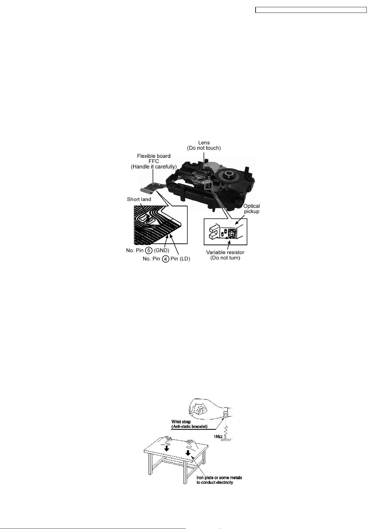
5.1. Handling Optical Pickup
1. Do not impact on optical pickup as the unit structurally uses an extremely precise technology.
2. Short-circuit the flexible cable of optical pickup remove from the circuit board using a short-circuit pin or clip in order to prevent
laser diode from electrostatic destruction (Refer to Fig. 3.1 and Fig. 3.2)
3. Do not handle flexible cables forcibly as this may cause snapping. Handle the parts carefully (Refer to Fig. 3.1)
4. A new optical pickup is equipped with an anti-static flexible cable. After replacing and connecting to the flexible board, cut the
anti-static flexible cable. (Refer to Fig. 3.1)
Fig 3.1
5.2. Replacing Precautions for Optical Pickup Unit
Optical Pickup
The optical pickup by which part supply was carried out attaches the short clip to the flexible board for laser diode electrostatic
discharge damage prevention. Please remove the short clip and be sure to check that the short land is open, before connecting.
(Please remove solder, when the short land short-circuits.)
5.3. Grounding for Preventing Electrostatic Destruction
1. Human body grounding
Use the anti-static wrist strap to discharge the static electricity accumulated in your body. (Refer to Fig. 3.2)
2. Work place grounding
Place a conductive material (conductive sheet) or ironboard where optical pickup is placed. (Refer to Fig. 3.2)
Note :
Keep your clothes away from optical pickup as wrist strap does not release the static electricity charged in clothes.
Fig. 3.2
11
SA-VK660GC / SA-VK660GS / SA-VK660GCS / SA-VK660GCT
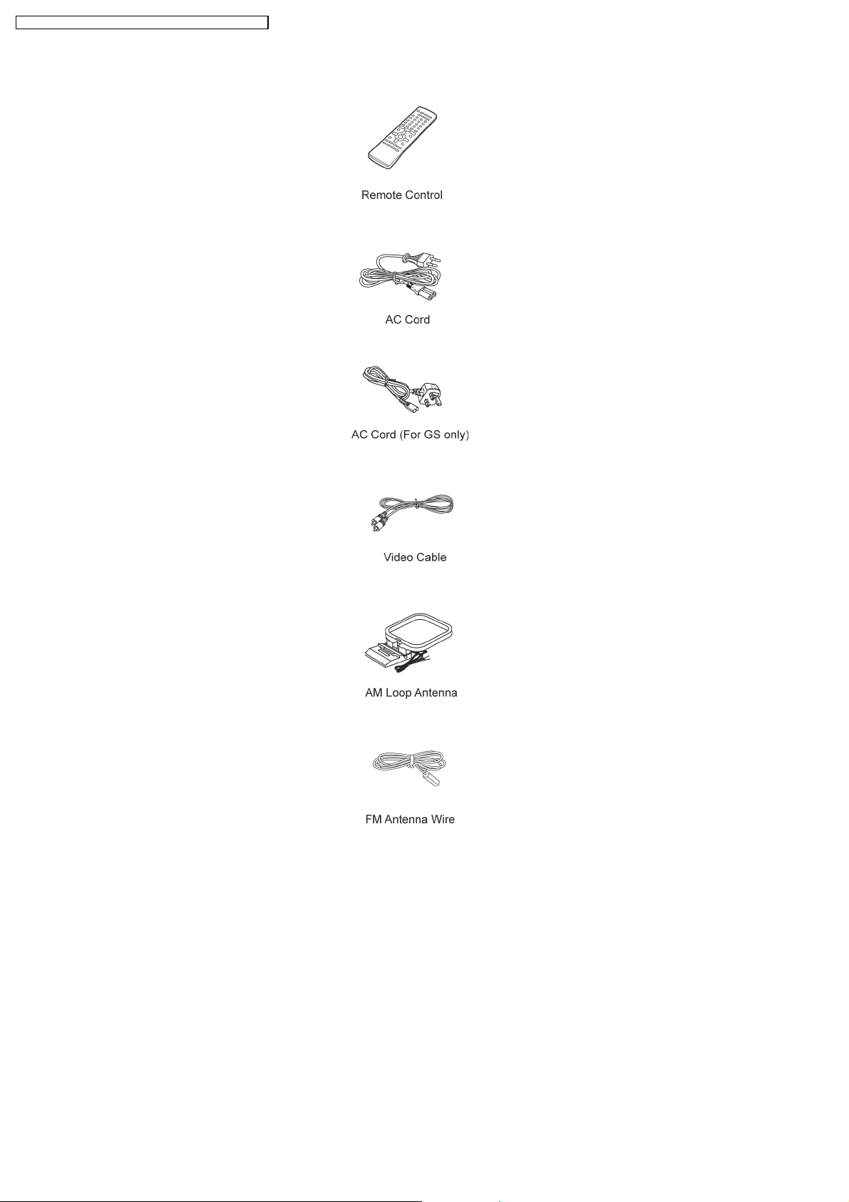
6 Accessories
12
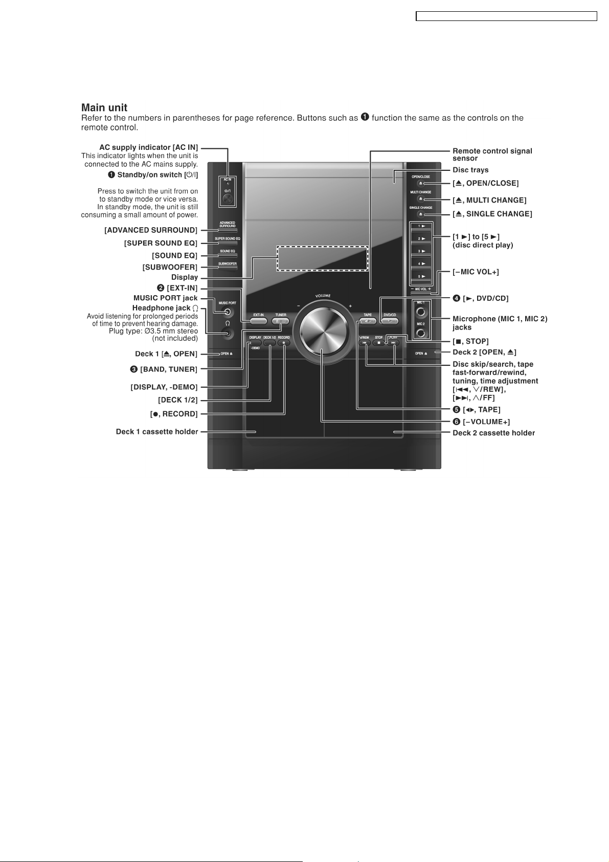
7 Operation Procedures
7.1. Main Unit Operation Control
SA-VK660GC / SA-VK660GS / SA-VK660GCS / SA-VK660GCT
13
SA-VK660GC / SA-VK660GS / SA-VK660GCS / SA-VK660GCT
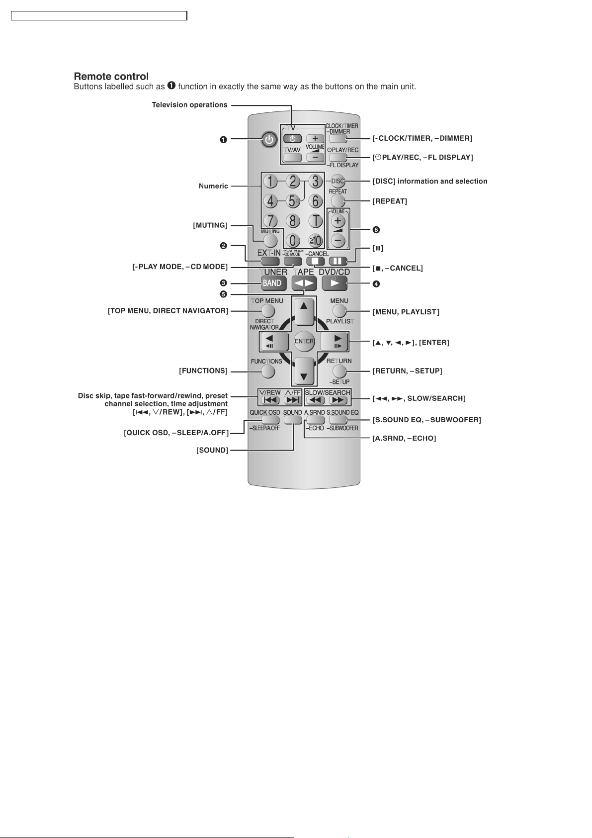
7.2. Remote Control Operation Control
14

7.3. Disc Information
7.3.1. Disc Playability
SA-VK660GC / SA-VK660GS / SA-VK660GCS / SA-VK660GCT
15

SA-VK660GC / SA-VK660GS / SA-VK660GCS / SA-VK660GCT
7.3.2. To Play MP3/WMA and still pictures (JPEG/tiff)
16

7.4. DivX VOD Content
SA-VK660GC / SA-VK660GS / SA-VK660GCS / SA-VK660GCT
17
SA-VK660GC / SA-VK660GS / SA-VK660GCS / SA-VK660GCT
8 DVD/CD Mechanism Changer Unit
8.1. CRS1D Mechanism Overview
18
SA-VK660GC / SA-VK660GS / SA-VK660GCS / SA-VK660GCT
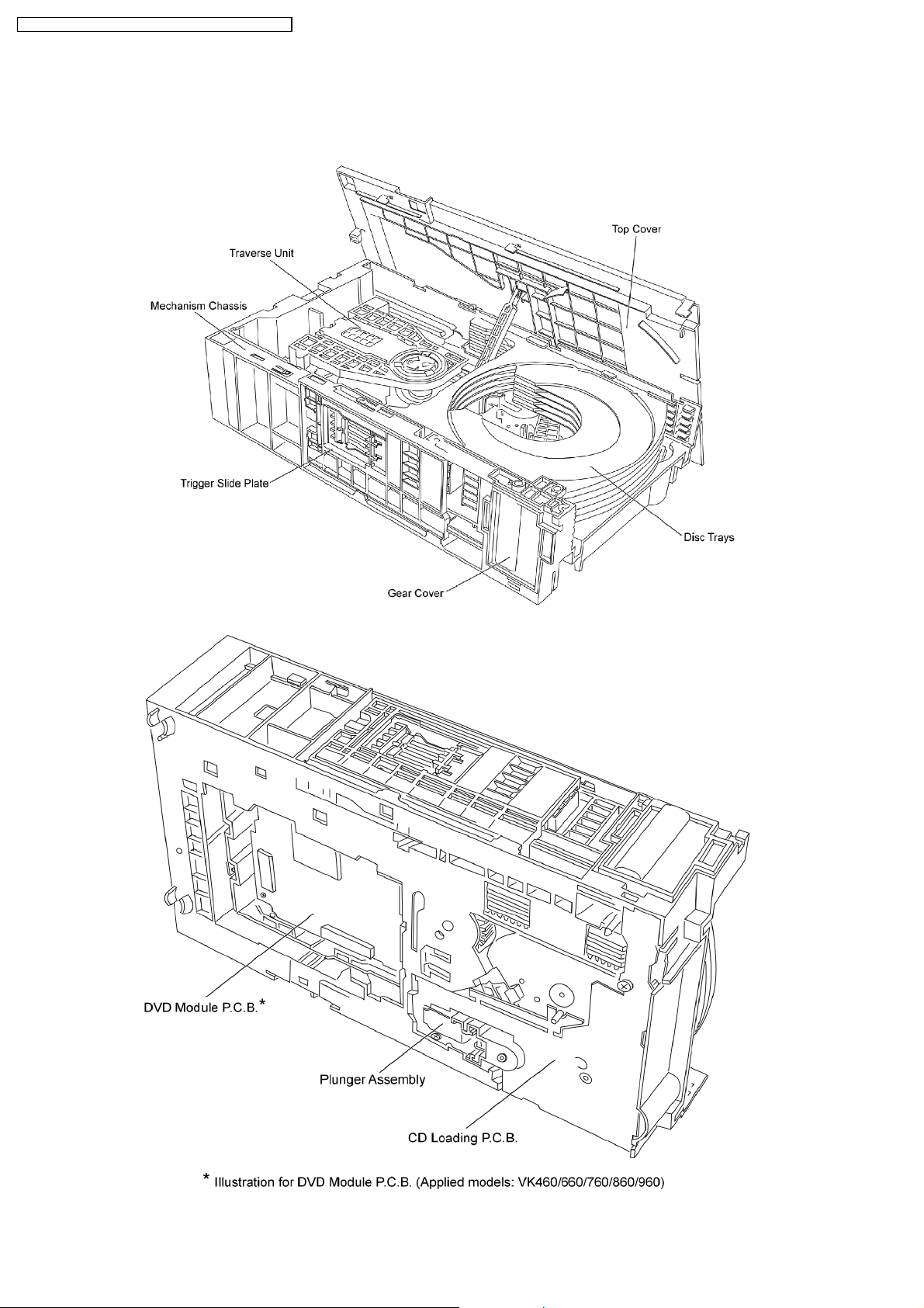
8.1.1. General Feature
•
• This is a five disc changer mechanism for CD/DVD. The outline figure is shown below.
• •
•
• The mechanism has "CHANGE WHILE PLAY" function. It open other trays for disc exchanging while one tray is at PLAY
• •
position performing recording or reproducing.
•
• The mechanism can quickly change all trays with "CHANGE ALL" function. All trays can be move to OPEN position with one
• •
operation.
•
• There is no sensor to indicate presence of disc on any tray.
• •
8.1.2. Hardware composition
•
• Below is the hardware components of the mechanism
• •
Name Function
Open Switch (OPEN-SW) The switch is used to detect normal tray opening
The switch is used for detect tray being manually push/trigger when full open
Home Switch (HOME-SW) Is used to detect cam gear home position
Close Sensor (CLOSE-SENSOR) Used for normal single tray closing
Used to detect cam gear rotate to Play Driving position
Play Switch (PLAY-SW) Detect TRV clamping complete position
Stocking Switch (STOCK-SW) Detect tray completely transfer for play position to stocking position
UD Sensor (UD-SENSOR) Detect TRV vertical movement position
Top Switch (TOP-SW) Detect a default position of TRV vertical movement position
Driver IC To drive Motor
Motor Main driving source for changer
Plunger Switching the driving source from motor to:
1. Tray open/close
2. Drive tray to play/stock position and TRV vertical movement
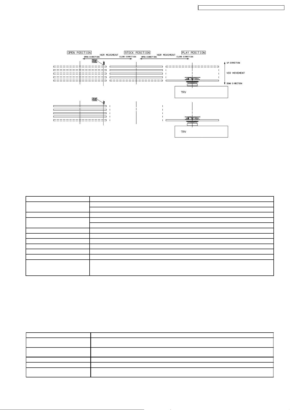
8.1.3. Mechanism Operation
•
• This mechanism has the following state:
• •
1. Driving of a tray to open/close
2. Up/down operation of a traverse performs a state changes of tray.
By using the plunger to lift/release of a switching gear, and the cam gear to lift/release the function gear the motor can be link
to several gear trains to perform various operations.
•
• The functions that can be perform in this mechanism are described as below:
• •
Condition Explanation
Open current playing tray The state to change current playing disc. All tray will be open at once and current tray at PLAY position
Open All The state where all trays being driven to OPEN position. The disc can be taken in or out from tray to tray
Stock The state where the trays are stored in STOCK position
Play The state where one of the tray 5 trays is being driven to PLAY position and clamped by traverse unit
Play & Open Tray-* The state where one of the tray is in playing position performing recording or reproducing, other trays can
will be expose.
by close tray one by one from top to bottom.
be used (OPEN position) for disc exchanging without stopping the recording or reproducing process.
19

SA-VK660GC / SA-VK660GS / SA-VK660GCS / SA-VK660GCT
Condition Explanation
Change The state when one of the opened tray being driven from OPEN position to STOCK position and other
Close All The state where all open trays will being driven from OPEN position to STOCK position, one by one from
Note: * represent tray number (from 1 ~ 5)
opened trays remain still at OPEN position.
top to bottom
8.1.4. DVD/CD Mechanism Changer Unit (CRS1D)
Note:
This service manual does not contain the following information for the mention DVD/CD Mechanism Changer Unit:
•
• Schematic Diagram, Block Diagram and P.C.B. layout of CD/DVD Loading P.C.B.
• •
•
• Part List for individual parts of the mechanism.
• •
•
• Exploded View and Parts List for individual parts of the DVD/CD Mechanism Changer Unit.
• •
Please refer to the original service manual (Order No. MD0603065A3) for the DVD/CD Mechanism Changer Unit (CRS1D).
20

8.2. Music Port
SA-VK660GC / SA-VK660GS / SA-VK660GCS / SA-VK660GCT
With reference to page 27 of the operating instruction manual.
21
SA-VK660GC / SA-VK660GS / SA-VK660GCS / SA-VK660GCT
9 Self diagnosis and special mode setting
This unit is equipped with functions for checking and inspecting.
9.1. Service Mode Summary Table
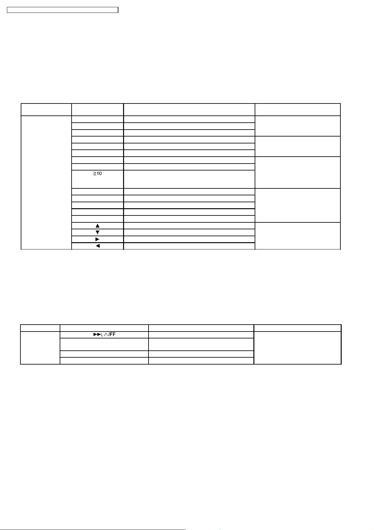
9.1.1. Service Mode Summary Table (For DVD)
The service modes can be activated by pressing various button combination on the player and remote control unit.
Below is the summary of major checking:
Player buttons Remote control unit
buttons
[STOP] [0] Error code display. (Refer to section, “9.2.1 of Service
[5] Jitter checking.
[PAUSE] Initial setting of laser drive current
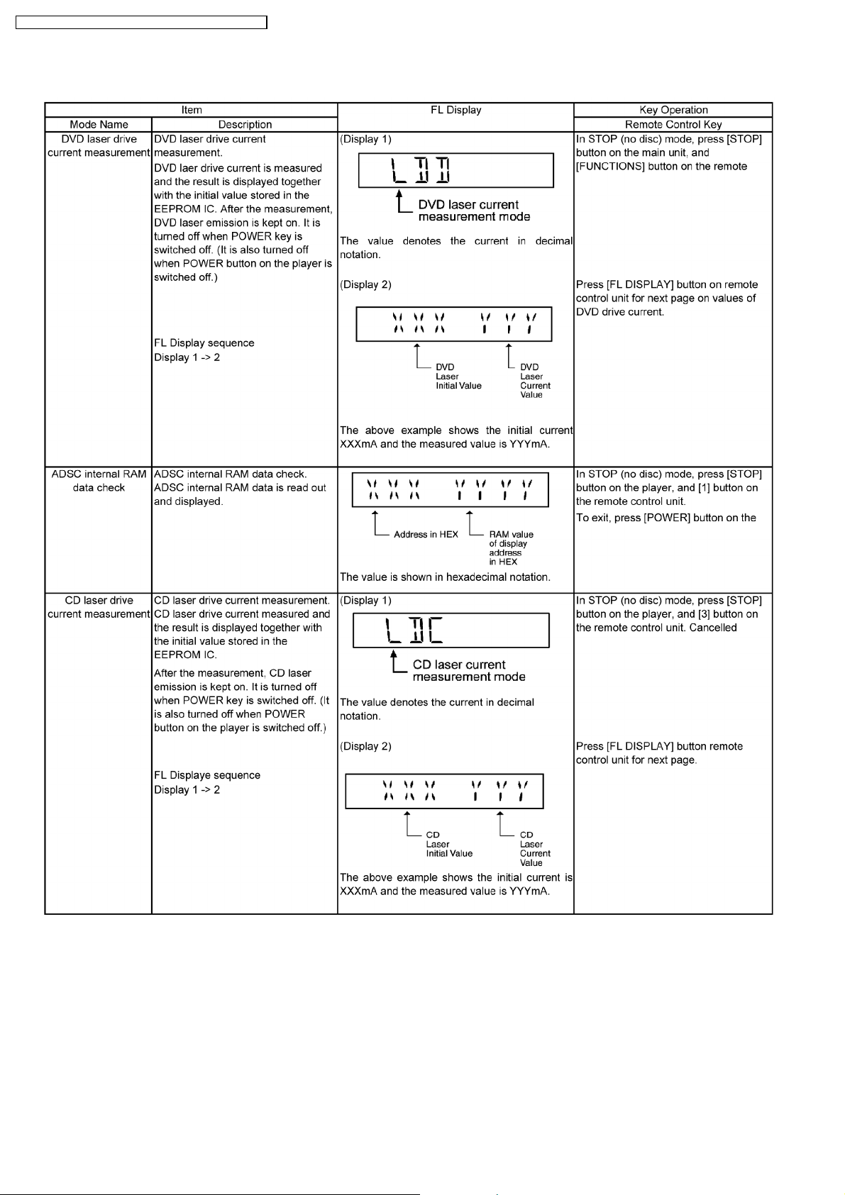
[1] ADSC internal RAM data check. (Refer to section 9.2.2 of Service
[3] CD laser drive current check.
[FUNCTIONS] DVD laser drive current check.
[6] Region display and mode. (Refer to section 9.2.3 of Service
[7] Micro-processor firmware version check.
[ ] Initialization of the player (factory setting is restored.)
Used after replacement of micro-computer (DV 5.0 LSI IC
(IC8611), FLASH ROM IC, EEPROM and HDMI module.
[8] DVD (HDMI) module firmware version check. (Refer to section 9.2.4 of Service
[MENU] Communication error display.
[TOP MENU] ECC error check.
[DISC] CPPM/CRM keys check.
[ENTER] DVD (HDMI) Module P.C.B. reset.
[ ] Timer 1 check. (Refer to the section, “9.2.5 Service
[ ] Timer 1 reset. (while in Timer 1 check)
[ ] Timer 2 check.
[ ] Timer 2 reset. (While in Timer 2 check)
Application Note
Mode Table 1” for more information).
Mode Table 2 for more information)
Mode Table 3 for more information)
Mode Table 4 for more information)
Mode Table 5” for more information).
Note:
An error code will be cancelled if a power supply is turned OFF.
*1: CPPM is the copy guard function beforehand written in the disc for protection of copyrights.
*2: CEC is the consumer electronic control used for high-level user control HDMI-connected devices.
*3: HDCP is the specification developed to control digital audio & video contents transmission for DVI or HDMI connections.
Refer to section 7 (Operating Instruction) for information on the buttons.
9.1.2. Service Mode Summary Table (For Inspection)
Player buttons Player/Remote Control Unit Buttons Application Note
[STOP] [ ] To enter into self-diagnostic checking. (Refer to section, “9.2.6 of Service
[1] DVD/CD Mechanism changer unit reliability
check.
[SINGLE CHANGE] To unlock the traverse unit for service.
[4], [7] To enter into Doctor Mode.
Mode Table 6” for more information).
9.2. Service Mode Table
By pressing various button combinations on the player and remote control unit can activate the various service modes for checking.
Special Note:
Due to the limitations of the no. characters that can be shown on FL Display, the “FL Display” button on the remote control unit
is used to show the following page. (Display 1 / Display 2).
22
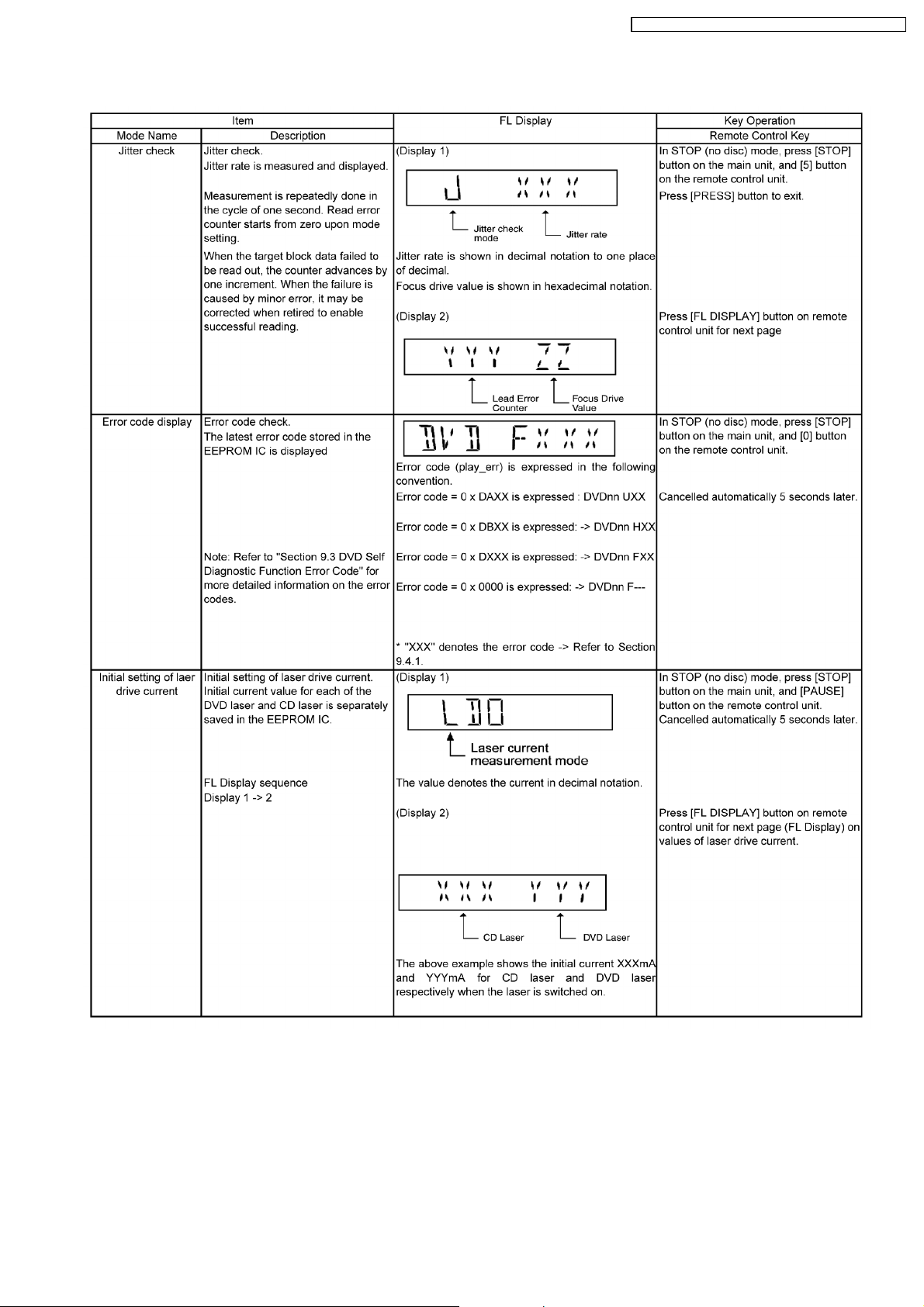
9.2.1. Service Mode Table 1
SA-VK660GC / SA-VK660GS / SA-VK660GCS / SA-VK660GCT
23
SA-VK660GC / SA-VK660GS / SA-VK660GCS / SA-VK660GCT
9.2.2. Service Mode Table 2
24
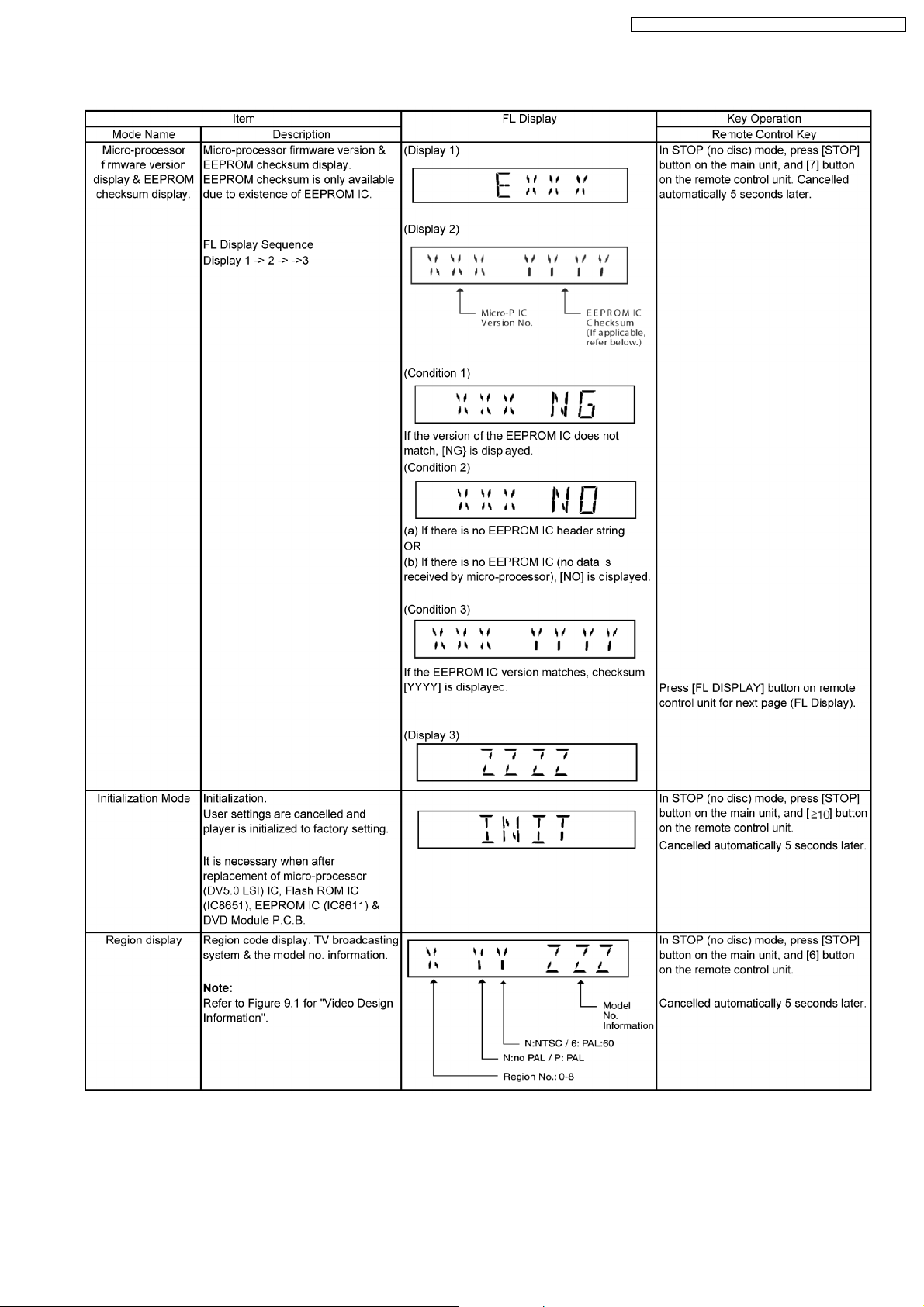
9.2.3. Service Mode Table 3
SA-VK660GC / SA-VK660GS / SA-VK660GCS / SA-VK660GCT
25

SA-VK660GC / SA-VK660GS / SA-VK660GCS / SA-VK660GCT
26
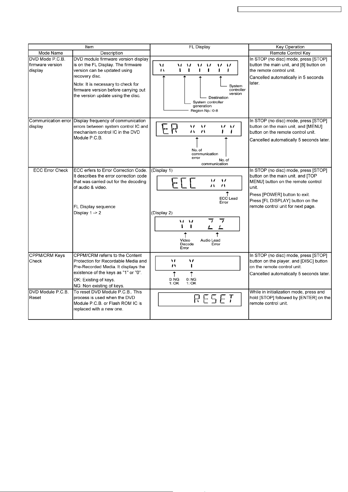
9.2.4. Service Mode Table 4
SA-VK660GC / SA-VK660GS / SA-VK660GCS / SA-VK660GCT
27
SA-VK660GC / SA-VK660GS / SA-VK660GCS / SA-VK660GCT
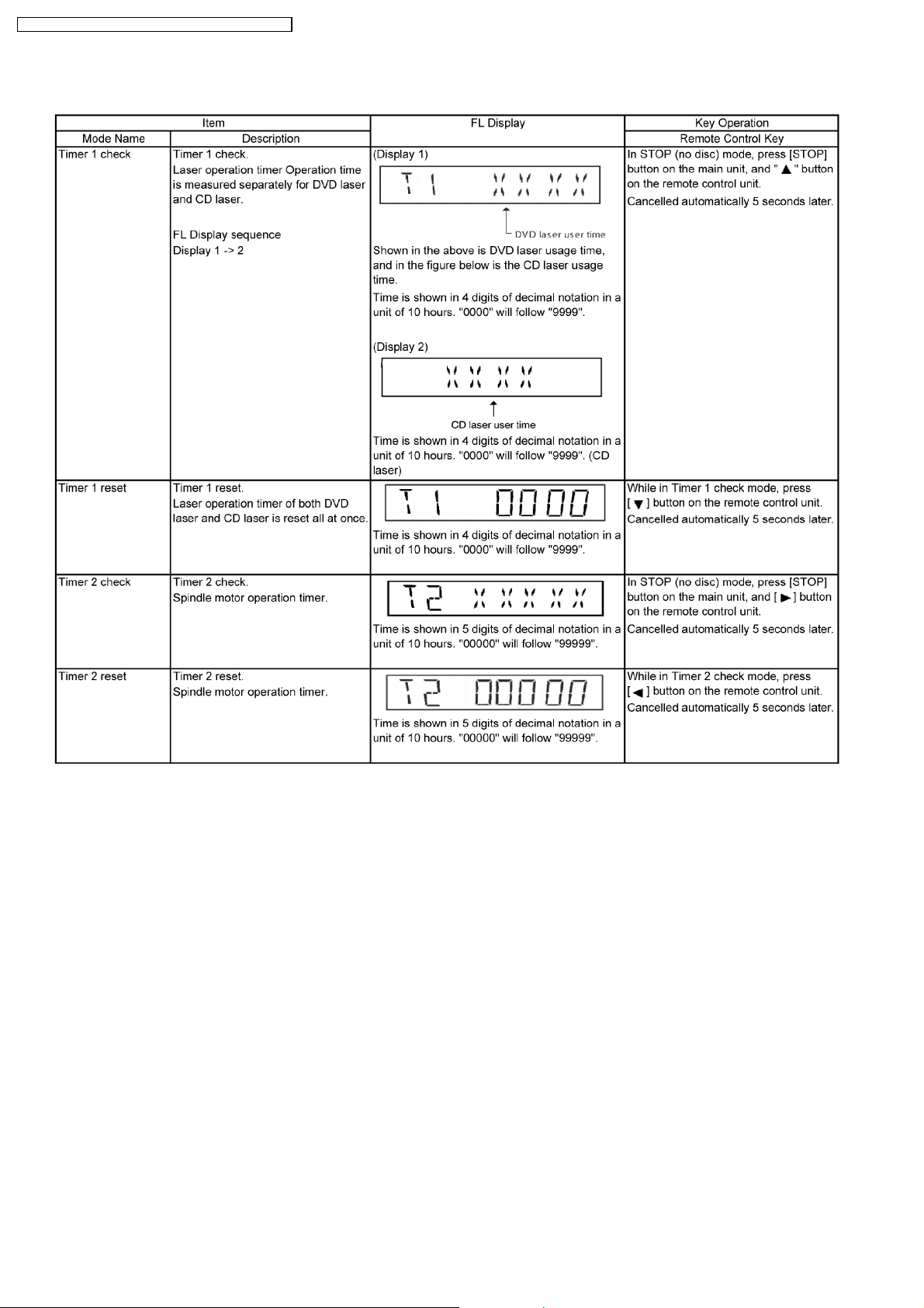
9.2.5. Service Mode Table 5
28
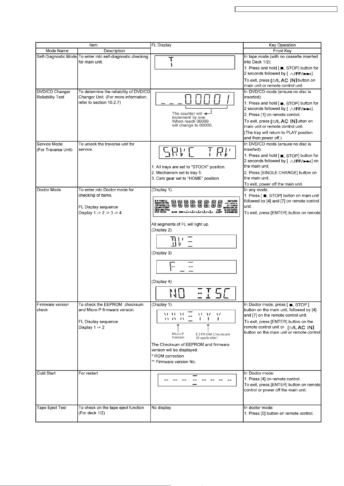
9.2.6. Special Mode Table 6
SA-VK660GC / SA-VK660GS / SA-VK660GCS / SA-VK660GCT
29
SA-VK660GC / SA-VK660GS / SA-VK660GCS / SA-VK660GCT
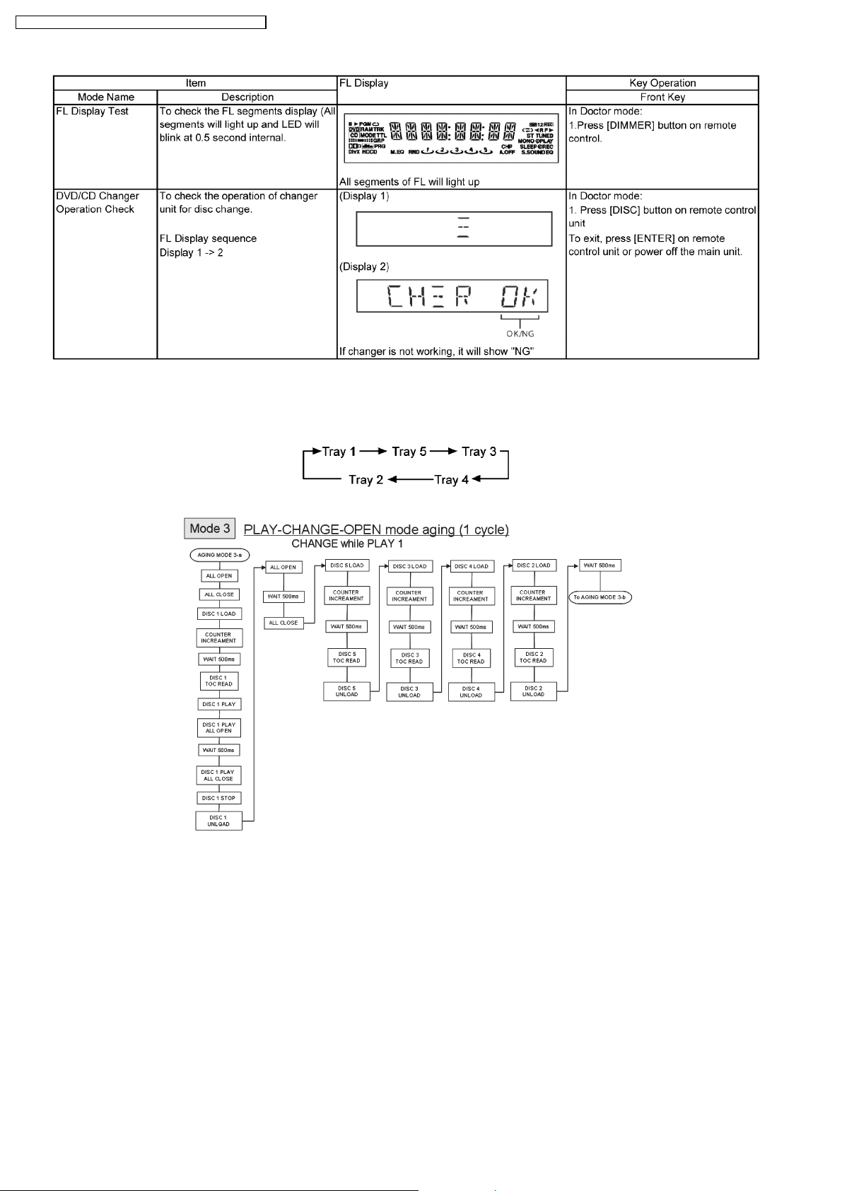
9.2.7. DVD/CD Mechanism changer unit ageing test mode
Below is the process flow chart of ageing for the DVD/CD Mechanism Changer Unit. (CRS1D)
30
 Loading...