


PRC 2000 SYSTEMS
SYSTEM OPERATION & MAINTENANCE MANUAL
1

2

MANUAL NO. 5050-0313
REV. G
3

TABLE OF CONTENTS
TITLE |
PAGE |
GeneralInformation .......................................................................................................................... |
7 |
Use Of This Manual ................................................................................................................... |
7 |
Introduction ................................................................................................................................ |
7 |
Specifications ............................................................................................................................ |
8 |
Capabilities ................................................................................................................................ |
10 |
Primary Controls ................................................................................................................. |
11 |
Pulse Heat .......................................................................................................................... |
12 |
Pulse Plate ......................................................................................................................... |
13 |
MicroChine .......................................................................................................................... |
14 |
Pik And Paste ..................................................................................................................... |
15 |
Thermal Management Center............................................................................................... |
16 |
Parts Identification ..................................................................................................................... |
18 |
System ............................................................................................................................... |
18 |
Front Panel Features ........................................................................................................... |
19 |
Rear Panel .......................................................................................................................... |
27 |
Safety ........................................................................................................................................... |
29 |
Set-Up ........................................................................................................................................... |
31 |
System ...................................................................................................................................... |
31 |
Handpiece Vacuum/Pressure ..................................................................................................... |
33 |
Procedures .......................................................................................................................... |
33 |
Operation ......................................................................................................................................... |
37 |
Introduction ................................................................................................................................ |
37 |
Definitions .................................................................................................................................. |
37 |
Thermal Management Center ..................................................................................................... |
38 |
Power Up ............................................................................................................................ |
39 |
Operation ............................................................................................................................ |
39 |
Factory Settings .................................................................................................................. |
|
Tip & Temperature Selection ................................................................................................ |
50 |
Password ............................................................................................................................ |
51 |
Calibration ........................................................................................................................... |
62 |
Temperature Limits .............................................................................................................. |
66 |
Temperature Setback .......................................................................................................... |
68 |
Automatic Power Down ....................................................................................................... |
72 |
Digital Readout Message Codes ......................................................................................... |
73 |
Quick Reference - System Operation .................................................................................. |
75 |
Foot Pedal ................................................................................................................................. |
78 |
4

|
TABLE OF CONTENTS |
TITLE |
PAGE |
Pik And Paste ..................................................................................................................... |
79 |
Paste Dispenser ............................................................................................................ |
79 |
Vacuum Pick ....................................................................................................................... |
86 |
MicroChine .......................................................................................................................... |
89 |
Set-Up ........................................................................................................................... |
89 |
Probe Brake Operation .................................................................................................. |
90 |
Pulse Plate .......................................................................................................................... |
93 |
Set-Up ........................................................................................................................... |
93 |
Pulse Heat ........................................................................................................................... |
97 |
Set-Up ........................................................................................................................... |
97 |
Operation ...................................................................................................................... |
99 |
ReferenceGuidelines .................................................................................................... |
100 |
CorrectiveMaintenance .............................................................................................................. |
103 |
VisiFilter Element Replacement ........................................................................................... |
103 |
Handpieces ......................................................................................................................... |
104 |
Power Source ...................................................................................................................... |
106 |
Replacement Parts .................................................................................................................... |
112 |
Power Source ...................................................................................................................... |
112 |
System Packaging .............................................................................................................. |
113 |
System Handpieces ............................................................................................................ |
114 |
System Accessories ........................................................................................................... |
115 |
SensaTempHandpieces ...................................................................................................... |
116 |
Manual Improvement & Comment Form ............................................................................... |
115 |
Warranty .................................................................................................................................... |
117 |
5

PACE, INCORPORATED RETAINS THE RIGHT TO MAKE CHANGES TO SPECIFICATIONS CONTAINED HEREIN AT ANY TIME, WITHOUT NOTICE.
THE FOLLOWING ARE REGISTERED TRADEMARKS AND/OR SERVICE MARKS OF PACE, INCORPORATED, LAUREL, MARYLAND, USA AND MAY ONLY BE USED TO IDENTIFY GENUINE PACE PRODUCTS OR SERVICES.
ARM-EVAC®, Flo-D-Sodr®, Mini-Wave®, PACE®, SensaTemp®, Snap-Vac®, SODRTEKSM, Sodr-X-
Tractor® , THERMO-DRIVE®, ThermoFlo®, ThermoJet®, ThermoTweeze®, TOOLNET®,VisiFilter®,
PERMAGROUNDTM, Tip-BriteTM, Auto-OffTM
Additional copies of this manual or other PACE literature may be obtained from:
www.paceworldwide.com |
|
|
PACEUSA |
PACEEurope |
|
9893 Brewers Court |
SherbourneHouse |
|
Laurel, MD 20723 |
SherbourneDrive |
|
USA |
|
Tilbrook, Milton Keynes |
|
|
MK78HX |
|
|
United Kingdom |
Tel: |
(301)490-9860 |
(44)01908-277666 |
|
(888)-535-PACE |
|
Fax: |
(301)498-3252 |
(44)01908-277777 |
6

USE OF THIS MANUAL
The information contained in this manual will provide the user with the basic knowledge necessary to properly operate and maintain the PACE model PRC 2000 system. The additional manuals included with your system will provide the user with specific operational features of the associated accessory. PACE STRONGLY RECOMMENDS THAT THE USER READ AND FULLY UNDERSTAND THE “OPERATION” PORTIONS OF THIS MANUAL PRIOR TO USE OF SYSTEM IN COMPONENT REMOVAL/ REPLACEMENT OPERATIONS. The “Quick Reference-System Operation” Guide is provided as a convenient reference for day-to-day operation of the Thermal Management Center portion of this system. If you encounter any difficulty operating your system, call your local authorized PACE distributor or contact PACE Applications Engineering directly at Tel. (301) 490-9860 or FAX (301) 604-8782.
INTRODUCTION
The PRC 2000 is a Process Control System for Universal Assembly and Repair of Electronic Assemblies. The systems include the power source with a selection of accessories and functional aids. The systems are available in a variety of package configurations to suit your needs.
The PRC 2000 systems are available in either the 100 VAC version, the 115 VAC version or the 230 VAC version. The Power Source houses five functional sections. The following is a brief description of each section.
The PRC 2000 THERMAL MANAGEMENT CENTER incorporates outputs for specialized SensaTemp handpieces for safe installation and removal of virtually all surface mount and thru-hole components. Three auxiliary channels provide SensaTemp control of separately sold AC line-powered accessories. Continuous automatic calibration, auto power down and a built-in software password function assure consistent operator performance, reliability and security.
The PIK AND PASTE section features a self-contained high pressure air supply with timing control for precise dispensing of solder paste and other materials. The vacuum pick has a finger actuated release for convenient component handling.
The PRC 2000 MICROCHINE is a lightweight, variable speed machining handpiece for precise circuitry and substrate repair. With its tachometer feedback, the MicroChine can maintain controlled drilling and milling rates under varying loads. The MicroChine’s patent pending PROBE BRAKE feature instantly stops machining at a selected layer depth for safe multilayer repair.
The PULSE HEAT section provides variable controlled, low voltage AC pulse power to an array of specialized handpieces for safe surface mount rework, circuitry repair, auxiliary heating, coating removal and thermal wire stripping.
7

INTRODUCTION CONT'D
The PULSE PLATE section provides variable controlled DC pulse power for high-quality cleaning and electroplating of edge connectors and other circuit contacts with nickel, gold and other metals.
The SR-4 “Safety Rating” designation on the back panel is your assurance that the PRC 2000 meets or exceeds all applicable civilian and military standards (including MIL-STD-2000A, and WS-6536), EOS\ESD and worldwide electrical codes. The 230 VAC version system bears the CE Conformity Marking which assures the user that it conforms to all the requirements of council directive EMC 89/336/ EEC. The 115 VAC version system bears the FCC Conformity Marking which assures the user that it conforms to all the requirements of FCC Emission Control Standard, Title 47, Part 15, Subpart B, Class A.
SPECIFICATIONS
POWER REQUIREMENTS
PRC 2000 (PPS 400 power source): Version operates on 97-127 VAC, 60 Hz. 250 Watts. PRC 2000J (PPS 400J power source): Version operates on 90-115 VAC, 50/60 Hz. 250 Watts.
PRC 2000E (PPS 400E power source): Version operates on 195-264 VAC, 50/60 Hz. 365 Watts.
PHYSICAL PARAMETERS
Size: 35 cm W x 17.5 cm H x 23 cm D (13.75 in W x 6.9 in H x 9.25 in D)
Weight: 13.6 Kg (30 Lbs)
ENVIRONMENTAL REQUIREMENTS
Ambient Operating Temperature: |
0°C to 50°C (32°F to 120°F). |
8

|
|
Storage Temperature: |
-40°C to 100°C (-40°F to 212°F). |
THERMAL MANAGEMENT CENTER
VACUUMANDAIR
Measurements at front panel SNAP-VAC and Controllable PRESSURE Ports of power source.
Vacuum Rise Time: |
Evacuates 33 cc (2 cubic inches) volume |
|
to 25 cm Hg. (10 in. Hg.) in 150 ms. |
Vacuum: |
51 cm Hg. (20 in. Hg.) (nominal) |
Pressure:. |
48 Bar (7 P.S.I.) (nominal MAX setting) |
Air Flow: |
13 SLPM (0.46 SCFM) maximum. |
TEMPERATURESPECIFICATIONS
Tip Temperature Range: 38°C to 482°C (100°F - 900°F) (see note).
Digital Readout Resolution: ± 1° (°C or °F)
Tip Temperature Stability: ± 1.1 °C (2°F) at idle from Set Tip Temperature.
NOTE
True minimum and maximum Operating Tip Temperatures may vary depending on handpiece & tip selection.
EOS/ESD
Tip-To-Ground
Resistance: Less than 5 ohms.
AC Leakage: Less than 2 millivolts RMS from 50Hz to 500Hz, min.
9

CAPABILITIES
Your new PRC 2000 is the most advanced, self-contained rework and repair system ever created for the service bench or manual production workstation. The case's T-slot channels allow you to configure PRC 2000 accessories to suit individual operator preferences. The new style Tip & Tool Stands and Hot Cubbies can be mounted to the T-slot channels or set up freestanding (with the purchase of optional "Stand Alone" cubby upgrades for Hot Cubbies). This offers great versatility when the unit is shared by several operators who may have different layout preferences.
10
PRIMARY CONTROLS
In the upper left hand corner, you will find the master POWER Switch which controls all power to the unit. Just to the right of the POWER Switch is a 4-position FOOT PEDAL Selector Switch which directs the action of the foot pedal connected to the FOOT PEDAL Receptacle (rear panel). This ensures that only one of the listed functions is activated by the foot pedal at any one time. The switch positions are as follows:
PH - Pulse Heat,
PP - Pulse Plate,
MC - MicroChine,
Figure 1. Primary ControlsPD - Paste Dispenser.
NOTE
Although vacuum and air pressure to air-operated SensaTemp handpieces is controlled by finger actuated handpiece switches, a second foot pedal can be connected to any Auxiliary (AUX) channel receptacles (rear panel) of the THERMAL MANAGEMENT CENTER to control vacuum or air pressure to these handpieces.
11

PULSE HEAT
At the lower left of the control panel you will find the PULSE HEAT section of the PRC 2000. The two AC jacks are for connecting the Universal Power Cord to the PRC 2000 system. The cord will accept several quick connect/disconnect handpieces including the LapFlo, ResisTweez, ConducTweez (optional) and StripTweez (optional) which can be changed within 2 seconds. Pulse Heat handpieces with nonsolderable, rapid heat up/cool down tips offer unique advantages in many SMT rework, conformal coating removal, soldering and auxiliary heating applications. With many Surface Mount Devices (SMDs) it is not only important to achieve the solder reflow temperature, but to control the way in which you arrive at that temperature. Many of the newer SMDs are very sensitive to thermal shock and overheating. The intrinsic slow temperature ramp-up (rise time) of the Pulse Heat handpieces provide an extra measure of safety for such components. Always consult your organization's specifications or the component manufacturer's guidelines. Some very sensitive components may require controlled preheating (e.g., with the PACE HotSpot temperature controlled heating surface).
Figure 2. Pulse Heat Section
12

NOTE
TheResisTweezresistancesolderinghandpiecebyitsverynaturemayhave a potential leakage voltage above 2mV. Its use should be restricted to soldering and auxiliary heating applications in which there is no risk of electrical over stress (EOS) discharge damage to sensitive components. PACE ThermoBand tips, which fit the ResisTweez, are specially insulated to keep leakage below 2mV.
The control knob located above the AC terminals (PULSE HEAT Output Control) controls the amount of energy delivered to the handpieces. The Green LED will light to indicate that current is flowing to the handpiece when the foot pedal has been depressed.
PULSE PLATE
The PULSE PLATE section located just to the right of the PULSE HEAT section allows the operator to safely replate
damaged, worn or repaired connectors, circuit contacts and edge connectors using simple plating solutions. The swab plating probe and ground clip connect to the terminals labeled “DC” while the control knob can be adjusted to regulate the amount of voltage applied to the area being plated. The Green LED will light to indicate that voltage is being applied when the foot pedal is depressed. The LED will shift from Green to Red if an overcurrent condition is reached. Contact your local PACE representative for information regarding the optional PE-210 SwaPlating accessory (P/N 7003-0002) to
the PRC 2000 system.
Figure 3. Pulse Plate Section
13

MICROCHINE
The MICROCHINE represents the latest PACE development in hand machining for the circuit board rework and repair. The self-contained motor handpiece connects to the PRC 2000 via a special connector. The motor unit can be actuated by a fingertip control switch or the foot pedal. A tachometer feedback loop between the motor and controller keeps the speed that you select constant as the load on the motor changes. Below and to the right of the MICROCHINE you will find a connection jack labeled “PROBE BRAKE” which offers additional control of milling and drilling operations. Connecting the probe to a conductive element where you wish machining to stop will cause the motor to stop immediately as soon as contact is made. This feature can also be used to protect other circuit elements (e.g., adjacent lands or circuit traces) when machining in the tight spaces often found on todays’ circuit assemblies. The LED will light Green when the unit is running and Red when the probe brake has been activated. The LED will shift its color from Green to Yellow when the motor has reached its maximum load. This is normally an indication that too much pressure is being applied to the workpiece. The control knob regulates the speed of the motor unit so that it can be easily set for the work to be performed. The MicroChine uses the same collet previously found in the PACE MiniChine systems, so that all existing bits will be interchangeable and features the same special static dissipative housing material found in all PACE soldering/desoldering handpieces. An optional chuck is available to accomodate variable shank diameter bits.
Figure 4. MicroChine Section
14

PIK AND PASTE
Located in the middle of the front panel, you will find the PIK AND PASTE section of the PRC 2000. The Pik-Vac feature provides a quiet and gentle vacuum source to the Pik-Vac wand for use in handling and placing your surface mount parts. Turning on the PIK-VAC Power Switch will cause a continuous vacuum to be made available to the pick. A variety of tip and vacuum cups are supplied to handle most surface mount parts. The Green LED will light to indicate when the PIK-VAC is running. There is also a low pressure auxiliary PIK PRESSURE Port located on the rear panel which can be used to operate low pressure accessories such as a sprayer.
The paste dispensing system occupies the right half of the PIK AND PASTE section of the PRC 2000 and can dispense a variety of solder cremes, fluxes, potting compounds and adhesives. The Paste Dispense air hose comes equipped to accept standard 10cc material barrels. The self-contained
pump supplies nominal 40psi (.28 MPa) of air pressure to the Figure 5. Pik And Paste Section syringe. Above the PASTE DISP Port, you will find a 2-
position switch labeled TIMED and CONT (Continuous). In the continuous (CONT) position the dispenser pump will supply continuous air pressure to the syringe while the foot pedal remains depressed (FOOT PEDAL Selector Switch in "PD" position). In the "TIMED" position, the control knob above the switch becomes active. Each depression of the foot pedal will activate the pump from 0.1 to 10 seconds. The LED will light
Yellow to indicate when the pump is running and will shift to Green when air pressure is being applied to the syringe.
NOTE
Whenever the FOOT PEDAL Selector Switch is in the “PD” position, the pumpwillperiodicallyrunforshortperiodstomaintaininternalpressure. The pump will continue to run (Yellow LED lit) while the system recharges.
NOTE
As with any dispensing system, when thick viscous material or solder paste is to be dispensed, ensure that the material is fresh, has been stored properly and is at room temperature as per supplier's recommendations.
15

THERMAL MANAGEMENT CENTER
The THERMAL MANAGEMENT CENTER occupying the right 1/3 of the front panel is the heart of your PRC 2000 system. This microprocessor based multi-channel center can control up to six devices at one time. To the left of the Digital Readout are the three LEDs which indicate the "Current Channel" (i.e., the channel whose temperature information can be adjusted and is displayed on the Digital Readout (CH 1, CH 2 and CH 3)). Below these is the Green AUX (Auxiliary) LED. When this LED is lit in conjunction with one of the channel LEDs, the Digital Readout displays temperature information of the three auxiliary channels located on the rear panel. To the right of the Digital Readout is the °F/°C Key which allows the operator to switch instantly between a ° F and ° C display. Located just below the Digital Readout is an array of five keys. In normal operation, these keys control channel selection, tip temperature and tip temperature offset settings. The two keys with up and down arrows are used for scrolling the temperature and offset settings up and down. The LEDs located above the SET and OFFSET Keys normally indicate which function is being adjusted. In Calibration (CAL) Mode, these same keys are also used for entering, setting and clearing the password features as well as adjusting temperature parameters and system set-up. By entering the tip temperature offset and the tip temperature, the true tip temperature will be displayed on the Digital Readout. All these features will be discussed in the operation section of the manual. Below the keys are three receptacles for attaching any three low voltage SensaTemp handpieces in any configuration up to 100 watts/channel (300 watts total) power. There are three additional receptacles on the lower left section of the rear panel. These will accept up to three additional, externally powered, devices which are temperature controlled by the THERMAL MANAGEMENT CENTER. As an alternative, any of the rear panel receptacles can accept a foot pedal which will control the internal vacuum/pressure pump in addition to using the finger-actuated switches found on the SensaTemp handpieces. SensaTemp handpieces available for use with your PRC 2000 include:
SP-2A Sodr-Pen Soldering Iron,
SP-1A Sodr-Pen Soldering Iron,
SX-70 Sodr-X-Tractor Handpiece,
TT-65 ThermoTweez Handpiece,
TP-65 ThermoPik Handpiece,
DTP-80 Dual ThermoPik Handpiece,
TJ-70 Mini ThermoJet Handpiece.
Just to the left of the three SENSATEMP receptacles is a grounding jack which will accept a standard banana plug. This can be used for grounding the operation, the work or additional equipment. To the right of the SENSATEMP receptacles you will find the SNAP-VAC Vacuum and Controllable PRESSURE Ports. The SNAP-VAC Port (bottom) should always have a VisiFilter attached in order to protect the vacuum pump from any ingested material and to help muffle noise when the motor is running. The Controllable
PRESSURE Port (top) is used to supply air to the Mini ThermoJet handpiece. The rate of delivered air flow 16

Figure 6. Thermal Management Center
17

PARTS IDENTIFICATION
SYSTEM
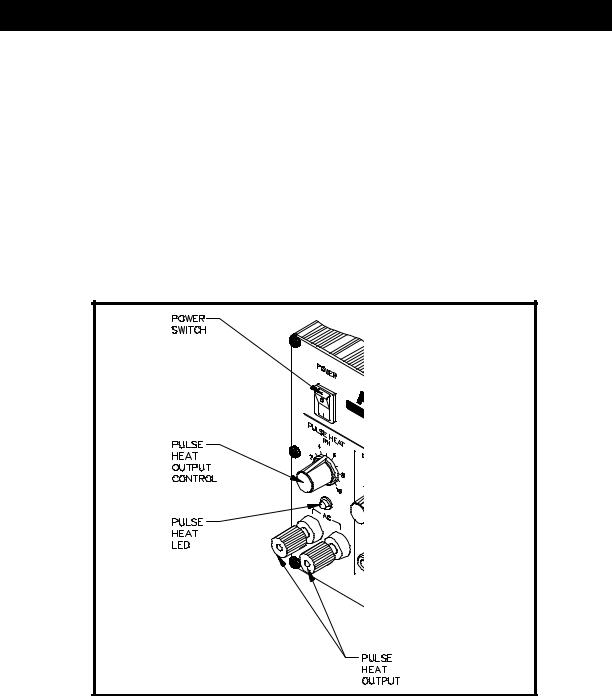
1.POWER SWITCH - Turns system ON (“1”) and OFF (“0”); controls input power to the system.
2.FOOT PEDAL SELECTOR SWITCH - Control knob provides foot pedal connection to Pik and Paste (PD), MicroChine (MC), Pulse Plate (PP) or Pulse Heat (PH) features.
POWER |
SWITCH |
Figure 8. Power Switch/Foot Pedal Selector Switch
18
FRONT PANEL FEATURES
PULSEHEAT
3.PULSE HEAT OUTPUTS - Low voltage AC power outputs for Low Voltage, Pulse Heat handpieces.
4.PULSE HEAT OUTPUT CONTROL - Controls low voltage AC power at PULSE HEAT Outputs.
5.PULSE HEAT LED - Illuminates Green in color when power is applied (by foot pedal through FOOT PEDAL Selector Switch) to the PULSE HEAT Outputs.
Figure 9. Pulse Heat Section
19
PULSEPLATE
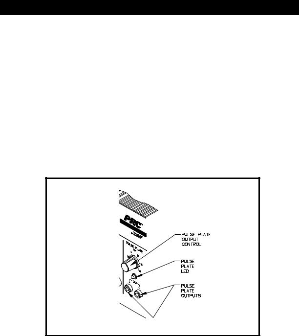
6.PULSE PLATE OUTPUTS - DC power connections for PACE SwaPlater plating system.
7.PULSE PLATE OUTPUT CONTROL - Controls DC power at PULSE PLATE Outputs.
8.PULSE PLATE LED - Illuminates Green to indicate when power is applied (upon foot pedal actuation) at the PULSE PLATE Outputs. Illuminates Red if an overcurrent condition occurs during plating.
Figure 10. Pulse Plate Section
20
MICROCHINE
9.MICROCHINE POWER RECEPTACLE - Provides power, speed control, tip ground and finger switch connection for the MicroChine handpiece.
10.VARIABLE SPEED CONTROL - Controls motor speed (2,500 - 10,000 RPMs) of MicroChine handpiece.
11.PROBE BRAKE RECEPTACLE - Provides Probe Brake connection for the MicroChine Probe Brake feature. See MicroChine portion of this manual for details.
12.STATUS LED - Illuminates Green to indicate MicroChine operation. Illuminates Amber if maximum torque load is reached. Illuminates Red to indicate braking status when Probe Brake circuit is activated.
Figure 11. MicroChine Section
21

PIK AND PASTE
13.PIK-VAC POWER SWITCH - Turns power “ON” (1) or “OFF” (0). Controls power to the Pik-Vac vacuumpump.
14.PIK-VAC LED - Illuminates Green to indicate Pik-Vac vacuum pump operation.
15.PIK-VAC PORT - Quick connect fitting which provides vacuum for Pik-Vac handpiece.
16.PIK AND PASTE TIMER CONTROL - Determines variable time controlled shot (0.1 - 10 seconds) of Paste Dispense (PASTE DISP) air pressure upon foot pedal actuation (Foot Pedal Selector Switch in "PD" position). Operates when TIMED/CONT Switch is in the “TIMED” position.
17.TIMED/CONT SWITCH - In CONT position, continuous air pressure is delivered from PASTE DISP Port upon foot pedal actuation (Foot Pedal Selector Switch in PD position). In "TIMED" position, measured interval of air pressure (0.1 - 10 seconds) is delivered from PASTE DISP Port upon foot pedal actuation (Foot Pedal Selector Switch in PD position).
18.PASTE DISP LED - Illuminates Green when air pressure is delivered from the PASTE DISP Port. Illuminates Yellow when the paste dispense pump reservoir is charging (no air pressure delivery from PASTE DISP Port).
19.PASTE DISP PORT - Quick connect fitting which provides air pressure (timed or continuous) to dispensing barrel.
22

Figure 12. Pik And Paste Section
23

THERMALMANAGEMENTCENTER
Refer to the illustration following for location of parts.
20.CH 1 POWER RECEPTACLE - Provides power, tip ground, sensing circuitry and finger switch connection from PRC 2000 system to handpiece connected to Channel 1 (CH 1).
21.CH 2 POWER RECEPTACLE - Provides power, tip ground, sensing circuitry and finger switch connection from PRC 2000 system to handpiece connected to Channel 2 (CH 2).
22.CH 3 POWER RECEPTACLE - Provides power, tip ground, sensing circuitry and finger switch connection from PRC 2000 system to handpiece connected to Channel 3 (CH 3).
23.SNAP-VAC PORT - Quick connect fitting which provides quick-rise vacuum for Sodr-X-Tractor or ThermoPik handpieces.
24.CONTROLLABLE PRESSURE PORT - Quick connect fitting with adjustable valve which provides variable air flow for Mini ThermoJet handpiece and Sodr-X-Tractor handpiece (in Hot Jet Mode).
25.DIGITAL READOUT - Provides a three digit display of the Current Channel (channel with illuminated LED; CH 1, CH 2, CH 3 or AUX 1, AUX 2, AUX 3) temperature information. This includes: Operating Tip Temperature in Temperature Display Mode (normal operation), Tip Temperature Offset Constant in TIP OFFSET Mode, Set Tip Temperature in TIP SET Mode, and other information in Calibration (CAL) Mode.
26.°F/°C KEY - Selects °F or °C display of Set and Operating Temperatures and Tip Temperature Offset Constants.
27.°F LED - Illuminates when Set and Operating Tip Temperatures and Tip Temperature Offset Constants are displayed in °F.
28.°C LED - Illuminates when Set and Operating Tip Temperatures and Tip Temperature Offset Constants are displayed in °C.
29.CH 1 LED - Illuminates when Channel 1 (CH 1) or Auxiliary Channel (AUX 1) is the Current Channel (i.e., the channel (with connected handpiece/tip or auxiliary accessory) whose temperature information is displayed on the Digital Readout).
24

30.CH 2 LED - Illuminates when Channel 2 (CH 2) or Auxiliary Channel (AUX 2) is the Current Channel (i.e., the channel (with connected handpiece/tip or auxiliary accessory) whose temperature information is displayed on the Digital Readout).
31.CH 3 LED - Illuminates when Channel 3 (CH 3) or Auxiliary Channel (AUX 3) is the Current Channel (i.e., the channel (with connected handpiece/tip or auxiliary accessory) whose temperature information is displayed on the Digital Readout).
32.AUX LED - Illuminates when an auxiliary channel (on system rear panel) is the Current Channel (i.e., the channel (with connected handpiece/tip or auxiliary accessory) whose temperature information is displayed on the Digital Readout). One of the CH 1, CH 2 or CH 3 LEDs will illuminate simultaneously with the Auxiliary LED to indicate, respectively, which of the auxiliary channels is active (AUX 1, AUX 2 or AUX 3).
33.CH SELECT KEY - Selects the Current Channel (among “Active Channels” (i.e., those with a connected handpiece or auxiliary accessory)).
34.TIP SET KEY - Allows the operator to adjust the Set Tip Temperature for the handpiece/tip combination or Set Temperature for the auxiliary accessory connected to the Current Channel. Places the THERMAL MANAGEMENT CENTER in the TIP SET (Tip Temperature Set) Mode.
35.TIP SET LED - Flashes when TIP SET Key is pressed indicating that the THERMAL MANAGEMENT CENTER is in TIP SET Mode.
36.TIP OFFSET KEY - Allows the operator to adjust the TIP OFFSET CONSTANT for the handpiece or auxiliary accessory connected to the Current Channel. Places the THERMAL MANAGEMENT CENTER in the TIP OFFSET(Tip Temperature Offset) Mode.
37.TIP OFFSET LED - Flashes when TIP OFFSET Key is pressed indicating that the THERMAL MANAGEMENT CENTER is in the TIP OFFSET Mode. Remains illuminated (not flashing) in Temperature Display Mode (normal operating mode) when a Tip Temperature Offset Constant of greater than “3” for °C (“6” for °F) is entered.
38.SCROLL UP KEY - Increases the Set Tip Temperature (in TIP TEMPERATURE SET Mode) and Tip Temperature Offset Constant (in TIP TEMPERATURE OFFSET Mode) in one, then ten degree increments. Also used in “CAL” (Calibration) Mode.
25

39.SCROLL DOWN KEY - Decreases the Set Tip Temperature (in TIP SET Mode) and Tip Temperature Offset Constant (in TIP OFFSET Mode) in one, then ten degree increments. Also used in “CAL” (Calibration) Mode.
40.EARTH GROUND RECEPTACLE - Provides positive earth ground to which a ground cable can be connected from the workpiece or work surface as part of a static control program.
Figure 13. Thermal Management Center Parts I.D.
26

REAR PANEL
41.AC POWER RECEPTACLE/FUSE HOLDER - Receptacle for providing power to the PRC 2000 system from AC outlet through power cord. Also location of fuse (F1) which protects the system from overcurrent conditions.
42.FUSE F1 - Provides overload protection for PRC 2000 system.
43.FOOT PEDAL RECEPTACLE - Input for foot pedal which operates the Pik and Paste, MicroChine, Pulse Plate or Pulse Heat features of the system as determined by the FOOT PEDAL Selector Switch.
NOTE
The Auxiliary Power Receptacles listed below (items 44-46) will provide temperature control for line operated auxiliary accessories or foot pedal operation only. SensaTemp handpieces will not function properly if connected to these outputs.
44.AUX 1 POWER RECEPTACLE - Provides temperature control, tip ground sensing circuitry and finger switch connection from THERMAL MANAGEMENT CENTER to the auxiliary accessory connected to Auxiliary Channel 1. Foot pedal attachment to this receptacle will allow vacuum/ pressure pump operation through foot pedal actuation.
45.AUX 2 POWER RECEPTACLE - Provides temperature control, tip ground sensing circuitry and finger switch connection from THERMAL MANAGEMENT CENTER to the auxiliary accessory connected to Auxiliary Channel 2. Foot pedal attachment to this receptacle will allow vacuum/ pressure pump operation through foot pedal actuation.
46.AUX 3 POWER RECEPTACLE - Provides temperature control, tip ground sensing circuitry and finger switch connection from THERMAL MANAGEMENT CENTER to the auxiliary accessory connected to Auxiliary Channel 3. Foot pedal attachment to this receptacle will allow vacuum/ pressure pump operation through foot pedal actuation.
47.FUSE F2 - Provides overload protection for CH 1, CH 2 and CH 3 power receptacles.
48.PIK PRESSURE PORT - Low pressure output with quick connect fitting. Controlled by PIKVAC Power Switch (front panel).
27

49.TIP & TEMPERATURE SELECTION SYSTEM CHART HOLDER (NOT SHOWN) - Holds PACE’s Tip & Temperature Selection System charts (booklet) which enable the operator to accurately set and display the true, correct operating tip temperature for any handpiece/tip configuration connected to CH 1, CH 2 or CH 3.
Figure 14. Rear Panel Parts I.D.
28

The purpose of this "SAFETY" section is to inform users of the heading guidelines used in this manual to indicate special Notes, Cautions, Warnings or Dangers. Also included are recommended precautions which must be observed when operating or servicing this product.
HEADING GUIDELINES
PACE adheres to the following Heading Guidelines (based on OSHA guidelines) when listing special information or precautions to be taken. Especially important are all procedures and practices which, if not strictly observed, could result in injury or loss of life.
These "NOTES", "CAUTIONS","WARNINGS" and "DANGERS" are inserted in this manual whenever deemed necessary. They appear in a blocked off form with double outline and a shaded background to highlight the information as shown below.
NOTE
XXXXXXXXXXXXXXXXXXXXXXXXXXXXXXXXXXXXXXXXXXXXXXXXXX
NOTE
Used to indicate a statement of company recommendation or policy. The message may relate directly or indirectly to the safety of personnel or protection of property. NOTE is not associated directly with a hazard or hazardous situation and is not used in place of "CAUTION", "WARNING" or "DANGER".
CAUTION
Used to indicate a hazardous situation which may result in minor or moderate injury. May also be used to alert personnel to conditions, procedures and practices which, if not observed, could result in damage to or destruction of the product or other equipment.
WARNING
Used to define additional information that if not closely followed might result in serious damage to equipment and represent a potential for serious personnel injury.
DANGER
Defines additional information that if not closely followed might result in severe personnel injury or death. Danger is not used for property damage unless personal injury risk is present.
29

PRECAUTIONS
The following are general safety precautions which personnel must understand and follow when using or servicing this product. These precautions may or may not be included elsewhere in this manual.
USEAGE PRECAUTIONS
CAUTIONS
1.SensaTemp handpiece heaters and installed tips are hot when handpiece is powered on. DO NOT touch either the heater or tip. Severe burns may result! Always store handpiece in the appropriate Tip & Tool Stand or cubby when not in use.
2.Always use this system in a well ventilated area. A fume extraction system such as those available from PACE are highly recommended to protect personnel from solder flux fumes.
3.Exercise proper precautions when using chemicals (e.g., solder paste). Refer to the Material Safety Data Sheet (MSDS) supplied with each chemical and adhere to all safety precautions recommended by the manufacturer.
NOTES
1.The solder collection chamber in the PACE Sodr-X-Tractor is made of glass. Never remove this chamber using pliers. Breakage of the chamber may result. Always remove using the procedures recommended by PACE in the associated handpiece manual.
2.The front end (heater end) of the glass solder collection chamber in the PACE Sodr-X-Tractor is hot when the handpiece is in use. When removing the chamber for cleaning, grip the chamber at the rear seal. Never touch the front end of the glass chamber with bare hands. Allow the chamber to cool before cleaning.
3.Always store any connected handpiece in the appropriate Tip & Tool Stand or cubby.
SERVICING PRECAUTIONS
DANGERS
POTENTIALSHOCKHAZARD-Repairproceduresperformedonthisproductshouldbeperformed by qualified service personnel only. Line voltage parts will be exposed when equipment is disassembled. Service personnel must avoid contact with these parts when troubleshooting the powersource.
NOTES
Refer to the PRC 2000 Service Manual (P/N 5050-0344) whenever service is required.
To insure continued peak performance, use genuine PACE replacement parts.
30
 Loading...