


 Loading...
TF 2000
BGA/CSP Rework System
MANUAL NO. 5050-0482
REV. C
Page 1 of 67
TABLE OF CONTENTS |
|
Safety................................................................................................................... |
4 |
Introduction .......................................................................................................... |
5 |
Packing Contents................................................................................................. |
5 |
Features............................................................................................................... |
7 |
Set-Up................................................................................................................ |
10 |
Operation ........................................................................................................... |
13 |
Before Operating ..................................................................................... |
13 |
General Operating Procedure ................................................................. |
13 |
Explanation of Each Operation........................................................................... |
17 |
Placing PCB into Board Holder ............................................................... |
17 |
Component Alignment and Placement .................................................... |
17 |
Component Reflow.................................................................................. |
19 |
Adjusting Airflow...................................................................................... |
20 |
Component Removal............................................................................... |
20 |
Selecting a Profile .............................................................................................. |
21 |
Creating and Saving Profiles.............................................................................. |
21 |
PC Software....................................................................................................... |
24 |
Setup Tab................................................................................................ |
25 |
Optics Tab Alignment View ..................................................................... |
27 |
Print/Review ........................................................................................... |
29 |
Operation Tab ......................................................................................... |
30 |
Process Control/Validation................................................................. |
31 |
Profile Development Tab......................................................................... |
33 |
General Information ........................................................................... |
34 |
Profile Creation .................................................................................. |
36 |
Maintenance....................................................................................................... |
39 |
Cleaning the Blower Filter ....................................................................... |
39 |
Replacing the Top Heater........................................................................ |
39 |
Alignment and Calibration .................................................................................. |
41 |
Page 2 of 67
PCB to Optics.......................................................................................... |
41 |
Sliding Shaft Holder (Indexing)................................................................ |
42 |
Vacuum Nozzle Planarity ........................................................................ |
33 |
Reflow Head Planarity............................................................................. |
44 |
Reflow Head – “Y” Directional Adjustment .............................................. |
46 |
General Troubleshooting.................................................................................... |
47 |
Initial Operation Flow Chart ..................................................................... |
48 |
Nozzle Operation Flow Chart .................................................................. |
49 |
Vacuum Pick Operation Flow Chart......................................................... |
49 |
General Troubleshooting Table ............................................................... |
51 |
TF 2000 L/LE Model Differences........................................................................ |
52 |
Installing the Board Holder ...................................................................... |
52 |
Bottom-Side Heaters ............................................................................... |
53 |
Sliding Shaft Holder Indexing .................................................................. |
54 |
Alignment and Calibration Differences .................................................... |
55 |
Specifications..................................................................................................... |
56 |
Instructions for using the Board Supports .......................................................... |
58 |
Accessory Items................................................................................................. |
59 |
Page 3 of 67
Safety
The following are safety precautions that personnel must understand and follow when using or servicing PACE products.
1.POTENTIAL SHOCK HAZARD - Repair procedures on PACE products should be performed by Qualified Service Personnel only. Line voltage parts may be exposed when the equipment is disassembled. Service personnel must avoid contact with these parts when troubleshooting the product.
2.To prevent personnel injury, adhere to safety guidelines in accordance with OSHA and other applicable safety standards.
3.Always use PACE systems in a well ventilated area. A fume extraction system, such as those available from PACE, is highly recommended to help protect personnel from solder flux fumes.
4.Exercise proper precautions when using chemicals (e.g., solder paste). Refer to the Material Safety Data Sheet (MSDS) supplied with each chemical and adhere to all safety precautions recommended by the manufacturer.
5.The following safety precautions cover use of PACE hot air systems/hand pieces (e.g., ThermoFlo®, ThermoJet®).
a)Be careful when using in places where there are combustible materials.
b)Do not use in the presence of an explosive atmosphere.
c)A fire may arise if a hot air hand piece is not used with care. Do not leave the hand piece unattended when in use.
d)The heater assembly housing and any installed nozzle are hot when the system is being cycled and for a period of time thereafter. DO NOT touch either the heater assembly housing, nozzle or direct heated air stream. Severe burns may result!
Page 4 of 67
Introduction:
Thank you for purchasing the TF 2000 BGA/CSP Rework Station. As electronic devices continue to get smaller, lighter and more compact, components and printed circuit boards are also becoming smaller and the amount of available space on PCBs is continually decreasing. In order to maximize board space, area array devices are growing in popularity. Area array devices are BGAs, CSPs and “micro-BGAs”, and Flip Chips. These devices require an optical overlay vision system to ensure proper placement and high levels of process control during rework to ensure successful installation. The TF 2000 has been specifically designed to rework these types of components and can also install and remove a variety of other SMT devices.
NOTE: This device complies with part 15 of the FCC rules. Operation is subject to the following two conditions: (1) This device may not cause harmful interference and (2) This device must accept any interference received, including interference that may cause undesired operation.
The TF 2000 also complies with 98/37/EC and 89/336/EEC.
Caution: During normal operation, the top heater, nozzle, bottom- side-heater(s) and halogen lamps will get hot. Do not contact them directly as serious injury could occur.
Packing Contents
TF 2000 with Video Monitor
1.TF 2000B, BE, BL, or BLE: 1 each
2.TF 2000R: 1 each
3.TF 2000P: 1 each
4.Video Monitor: 1 each
5.B/C Video Cable: 1 each
6.Hand Held Vacuum Pick for removal: 1 each
7.Suction rubber (spare for #9): 3 each
8.Vacuum nozzle for positioning: 1 each Large, Medium and
Small sizes
9.Hex Wrench Set and Screwdriver: 1 each
10.Top Heater Element (spare): 1 each
11.Halogen Lamp (spare): 2 each
12.TF 2000 Manual: 1 each
13.K-Type ThermoCouple: 2 each
Page 5 of 67
TF 2000 with PC
1.TF 2000B, BE, BL, or BLE: 1 each
2.TF 2000R: 1 each
3.TF 2000P: 1 each
4.Computer: 1 each
5.Computer Monitor: 1 each
6.S-Video Cable: 1 each
7.TF 2000 Software Package: Installed on PC
8.Serial Cable: 2 each
9.Hand Held Vacuum Pick for removal: 1 each
10.Suction rubber (spare for #9): 3 each
11.Vacuum nozzle for positioning: 1 each Large, Medium and
Small sizes
12.Hex Wrench Set and Screwdriver: 1 each
13.Top Heater Element (spare): 1 each
14.Halogen Lamp (spare): 2 each
15.TF 2000 Manual: 1 each
16.K-Type ThermoCouple: 2 each
Page 6 of 67
Features
1. The TF 2000 System is comprised of three self-contained stations:
The Reflow Station (Model TF 2000R)
The Placement Station (Model TF 2000P), and
The Base/Pre-Heater Station (Models TF 2000B, TF 2000BE, TF
2000BL, or TF 2000BLE)
Each individual station is lightweight and compact, allowing for easy set-up and portability.
2.Up to 40 reflow profiles can be stored by the TF 2000. Saved profiles can be recalled at the touch of a button and are displayed on the LCD display panel.
3.A colored LED indicates each phase of the reflow cycle so the status of each operation can be easily seen and monitored.
4.The Placement Station can easily handle components up to 70 mm square. If needed, a split screen function is available through the optional software package.
5.A highly efficient, 1000-watt topside heater used in conjunction with a truly unique nozzle design insures the uniformity of the temperature across the assembly.
6.The ceramic panel bottom side heater with a wide heating area is incorporated to insure the co-planarity of the PCB, to prevent warping, and to enhance the reflow of large BGAs.
7.The blower and vacuum pumps are self-contained. No external air supplies are required.
8.A cooling fan automatically activates at the end of the reflow cycle to cool the component, PCB, and nozzle.
9.The TF 2000 is versatile, adaptable and ensures repeatable results.
Page 7 of 67

TF 2000R |
TF 2000P |
G
A
B
O |
|
|
H |
|
|
|
|
||
C |
|
|
|
|
D |
|
|
I |
|
E |
|
|
||
|
|
|
||
N |
|
|
J |
|
|
|
|
||
|
|
|
||
P |
|
|
|
|
|
|
|
|
|
F
L
K |
|
|
|
M |
|
|
TF 2000B or TF 2000BE
Figure 1: TF 2000 BGA/CSP Rework Station
Features:
Please refer to Figure 1.
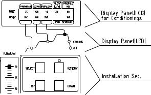
A) |
LCD Display Panel |
Displays profile variables (time and temperature) |
|
|
and allows the user to enter/modify profile |
|
|
parameters. |
B) |
Phase Display Panel |
Each phase of the reflow cycle is indicated by this |
|
|
panel. |
C) |
Data Entry Panel |
Used to enter/modify reflow profile parameters and |
|
|
to save or recall profiles. |
Page 8 of 67
D) |
Operations Panel |
Allows the operator to start/stop a profile cycle, |
|
|
turn on/off the cooling fan and raise/lower the |
|
|
reflow head. |
E) |
Air Flow Meter |
This device is used to control and monitor the |
|
|
airflow. |
F) Cooling Fan |
The component and the PCB are cooled down by |
|
|
|
the cooling fan, which activates automatically, |
|
|
after the reflow cycle is completed. |
G) |
Alignment Apparatus |
X, Y, Z and Θ aspects of the component position |
|
|
are adjusted in relation to the land pattern on the |
|
|
PCB through this apparatus. |
H) |
Camera Control |
The zoom and focus functions of the optical |
|
|
overlay system are controlled at this location. The |
|
|
Auto-focus feature may also be selected. |
I) |
Light Control |
The upper (component side) and lower (PCB side) |
|
|
lights within the optics housing can be adjusted for |
|
|
intensity (overlay contrast) at this location. |
J) |
Optics Housing |
Contains the camera and beam splitter. The |
|
|
housing is retractable and should be kept in the |
|
|
retracted position when not in use. The lights for |
|
|
the optics will turn on/off automatically when the |
|
|
housing is extended. |
K) |
Bottom Side Heater |
Used to warm the PCB from the underside. It is |
|
|
an IR type of heating source. The pre-heater |
|
|
temperature is set in the “PRE-HEAT” display and |
|
|
will remain on throughout the reflow cycle. When |
|
|
the cycle enters the reflow phase, the bottom-side |
|
|
heater temperature will increase by 30ºC to ensure |
|
|
successful reflow. A power consumption indicator |
|
|
light is mounted onto the pre-heater to indicate |
|
|
when it is drawing power. |
|
|
**NOTE: For TF 2000L/LE models, refer to |
|
|
Section 10 for model differences. |
L) |
Board Holder |
The board holder is fully adjustable in both the X |
|
|
and Y directions. The right side of the holder is |
|
|
spring loaded to hold the PCB securely. Fine |
|
|
adjustment in the X direction is achieved by using |
|
|
the adjustment knob on the Sliding Shaft Holder. |
Page 9 of 67
M) Sliding Shaft Holder |
Supports the rail system for the board holder. It is |
|
also used to index the table from the Placement |
|
Position to the Reflow Position using the handle |
|
on the front. |
N) Sensor 1 & 2 Inputs |
The sensor inputs have been designed to use K- |
|
type thermo-couples. Measured temperatures are |
|
displayed on the LCD display, real time, and can |
|
be interfaced to a PC using the TF 2000 Software |
|
(optional) through the serial port on the back of the |
|
TF 2000R. |
O) Reflow Head |
Contains the top-side heater and moves up and |
|
down via an electric motor that is controlled |
|
through the operations panel. A power |
|
consumption indicator light is mounted onto the |
|
front of the reflow head to indicate when it is |
|
drawing power. The reflow head is clutched to |
|
prevent excessive downward force from being |
|
applied. |
P) Nozzle |
The nozzles for the TF 2000 are easily changed. |
|
Several varieties are available. Use caution and |
|
proper hand protection when changing nozzles, as |
|
they will be hot. |
**NOTE: For TF2000 L/LE models, refer to Section 10 for a detailed description of model differences.
Page 10 of 67
1SET-UP
TF 2000 Setup & Connection to Video Monitor
1-1 Place the TF 2000B, TF 2000BE, TF 2000BL, or TF 2000BLE on a flat and stable bench. Refer to Section 10 for board holder installation on L/LE models.
1-2 Place the TF 2000R and TF 2000P on the base as indicated in
Figure 1.
1-3 Secure the TF 2000R and TF 2000P by following the directions in the box containing the base unit. Refer to Figure 1.
1-4 Connect the power cables as indicated in the wiring diagram label on the back of the units. See Figure 2.
1-5 Connect the hand-held vacuum pick to the vacuum port on the front of the TF 2000P and hang the vacuum pick on the side of the TF
2000P using the bracket provided.
1-6 Connect a B/C cable (included) and a power cable between the video monitor and the TF 2000P
1-7 Connect the main power cable to an appropriate 115 VAC, 60 Hz or
230 VAC 50 Hz power supply.
 Access Panel


 Wiring Diagram
Figure 2: Back of TF 2000
Page 11 of 67
TF 2000 Set up & Connecting to PC (Optional Package)
1-1 Place the TF 2000B, TF 2000BE, TF 2000BL, or TF 2000BLE on a flat and stable bench.
1-2 Place the TF 2000R and TF 2000P on the base as indicated in
Figure 1.
1-3 Secure the TF 2000R and TF 2000P by following the directions in the box containing the base unit. Refer to Figure 1.
1-4 Connect the power cables as indicated in the wiring diagram label on the back of the units. See Figure 2.
1-5 Connect the hand-held vacuum pick to the vacuum port on the front of the TF 2000P and hang the vacuum pick on the side of the TF 2000P using the bracket provided.
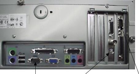
1-6 Connect the S-video cable (included) to the S-video port on the back of the TF 2000P. Then connect the other end of the cable to the S-video port on the back of the video expansion card on the PC. (See Figure 3)
1-7 Connect the serial port on the back of the TF 2000R to Serial
Port 1 (located next to the monitor port) on the computer using one 9 pin serial cable (included). (See Figure 3)
1-8 Connect the serial port on the back of the TF 2000P to Serial Port 2 on the computer using the other 9 pin serial cable (included). (See Figure 3)
1-9 Connect the power cable to an appropriate 115 VAC, 60 Hz or
230 VAC 50 Hz power supply.
1-10 Do not plug the PC or PC monitor into 1 amp power receptacle on the back of the TF 2000P.
SERIAL PORT 1 |
S-Video PORT |
SERIAL PORT 2 |
Figure 3: PC Back Panel
Page 12 of 67
2 OPERATION
2-1 Before Operating
•Make sure the TF 2000 is on a stable platform
•It is recommended that the TF 2000 be turned on for at least 15 minutes before use to ensure the Bottom Side heater has reached its set temperature and stabilized. Once the bottom-side heater is at temperature it will deliver consistent heating, ensuring highly repeatable heating from operation to operation.
•It is advisable to conduct a trial operation each day to ensure all systems are operating properly. Also, it is important to verify the airflow of the unit: Maximum airflow is 25 l/min and Minimum airflow is 18 l/min.
•Verify that the devices/parts being soldered to the PCB do not exceed the height limitations. Exceeding the limitations may interfere with the operation of the machine.
1.The maximum height of any component or device on the top of the PCB is limited to 30 mm (1.2”).
2.The maximum height of any component or device on the bottom of the PCB is limited to 15 mm (0.6”).
2-2 General Operating Procedure
1. Insert PCB into Board Holder. See Figure 4.
PCB
BOARD HOLDER
Figure 4: Board Holder and PCB
2.Apply flux or solder paste: One of the following methods is applicable depending on the rework conditions, the specification of
Device/PCB, or operator preference.
A)Dispense flux on the land pattern using a brush or flux pencil.
B)Apply solder paste to the land pattern using a conventional stenciling technique
C)Apply paste or flux to the BGA, solder ball side, by means of a flux application tool. See Reference Section.
Page 13 of 67
D)Print paste on the BGA, solder ball side, by using a component stenciling tool kit. See Reference Section.
Note: Method 2 must be completed prior to insertion of PCB into board holder and methods 3 and 4 apply flux/paste to the underside of the component, not the PCB. They should be performed before placing component with vacuum pick on TF 2000P.
3.Activate vacuum on TF 2000P and pick up component using vacuum nozzle on placement station.
Figure 5: Component held by Vacuum Pick on TF 2000P
4.Pull the optics housing out from the front of the TF 2000P using the handle. Be sure the Sliding Shaft Holder is in the placement position.
5.Align component solder ball/lead pattern to the land pattern on the
PCB using the adjustment knobs on the alignment apparatus. See Figure 6. The BGA ball side and the PCB pattern side are superimposed on the video or computer monitor, depending on chosen configuration, by the optical system.
Page 14 of 67
10
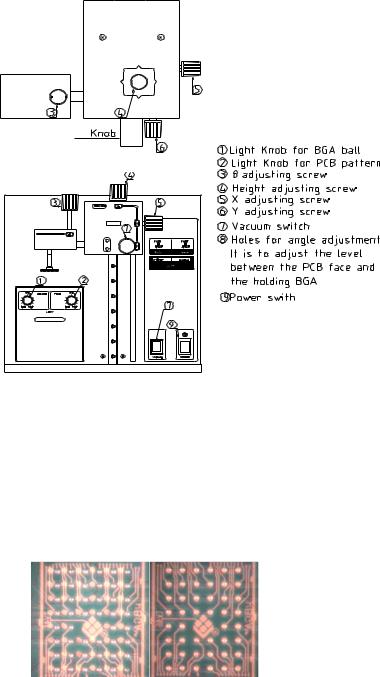
Figure 6: TF 2000P
A)Zoom in so the lands on the PCB fill the screen and center the land pattern on the display.
B)Adjust the lighting so both images are clear.
C)Align the component to the land pattern using the X,Y and Θ. See Figures 6 and 7.
(A)(B)
Figure 7 - Unaligned (A) and Aligned component (B) as they would appear.
6.Lower the Alignment Apparatus to PCB.
7.Release component by turning off the vacuum and return alignment apparatus to the upper position. See Figure 6.
Page 15 of 67
8.Using the handle on the Sliding Shaft Holder, index the table from the Placement Position to the Reflow Position.
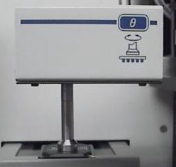
9.Select the desired profile or enter time and temperature parameters for pre-heat, soak, and reflow phases. Those values will be shown on the LCD display. See Figure 8. As each phase in the reflow profile is entered, the LED indicator lights will show which phase the process is in. See Figure 8.
Figure 8: Display and Data Entry Panel
10.Once the reflow profile has been completed, the reflow head will lift up automatically and the cooling fan will turn on for 55 seconds.
Airflow from the cooling may be directed by loosening the locking thumb screw on the fan and rotating it around its shaft.
Page 16 of 67
3EXPLANATION OF EACH OPERATION
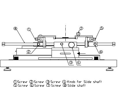
3-1 Placing BCB into Board Holder - Please see Figure 9.
1.Center the sliding shaft (8) in the holder (9).
2.Adjust the sides of the board holder so that the distance between them is 3 mm smaller (half the width of the rail) than the width of the PCB. Secure the sides by tightening the setscrews (6 & 2)
3.The right side of the board holder is spring loaded. Insert the PCB into the support slots while holding the right side of the board holder open. When the PCB is positioned, let the right side close.
9
Reflow Position |
Placement Position |
9) Sliding Shaft Holder
Figure 9: Board Holder and Base
3-2 Component Alignment and Placement - Please refer to Figures 6 and 9.
1.Set the sliding shaft holder at the Placement Position at the far right side of the base
2.Verify that the height (Z-axis) adjusting screw (#4, Fig. 6) is positioned in the center of the square hole as shown in Figure 4. This position is the reference point for all alignment procedures.
3.Extend the optical housing by pulling the handle towards you. The lights will come on automatically.
4.Focus the array pattern on the PCB by focusing manually or by using the AUTO FOCUS feature. When using the AUTO FOCUS feature, switch the feature off after the array pattern has been focused.
5.Center the PCB array pattern on the Display. Zooming in on the array allows for easier centering.
Page 17 of 67
6.Tighten the setscrews (#1 & 5, Fig. 9) to secure the “Y” position of the PCB.
7.Tighten the setscrew (#3, Fig. 9) on the sliding shaft holder (#9, Fig.
9) to secure ”X” position of the PCB.
8.Switch on the vacuum switch (#7, Fig. 6).
9.Hold the component to be placed using the vacuum nozzle. See
Figure 7.
10.Adjust the lighting using the adjustment knobs (#1 & 2 Fig 5) so the image of the PCB land pattern and the image of the solder balls on the component can be seen clearly.
11.Adjust the height of the device with the height (Z-axis) adjusting screw (#4 Fig 5) to bring solder balls/leads into focus. Failure to focus the component may result in inaccurate alignment.
12.Turn the “AUTO-FOCUS” feature on after the PCB and component are focused.
13.Adjust θ aspect of the component by turning the θ adjustment knob (#3, Fig. 6).
14.Adjust the X and Y aspects of the component by adjusting the X and Y adjustment knobs (#5 & 6, Fig. 6).
15.When the component is aligned (See Figure 7), return the optics housing to its retracted position. The lights will turn off automatically.
16.Using the handle, lift the alignment apparatus upwards by hand to release, then lower the apparatus slowly. As the apparatus reaches the PCB, the damper will engage to ensure the component lands softly on the PCB.
NOTE: The alignment apparatus cannot be lowered while the optics housing is extended.
DO NOT DROP THE ALIGNMENT APPARATUS FROM THE UPPER POSITION.
NOTE: When repeating operations using the same PCB and device, steps 4 and 11 may be eliminated. However, when changing devices, it is important to include steps 4 and 11 in the initial setup procedure.
3)Confirm that the component has contacted the PCB. Turn off the vacuum switch (#7, Fig 6).
When repeating operations using the same PCB and device, the mechanical stop on the right side of the alignment apparatus may be set to ensure repeatability.
4)Return the alignment apparatus to its original position.
Page 18 of 67
19)Move the sliding shaft holder to the Reflow Position using the handle.
NOTE: For TF 2000L/LE models, refer to the Sliding Shaft Holder Indexing portion of Section 10 for a description of model differences.
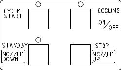
3-3 Component Reflow - Please refer to Figure 10
1)Make sure that an appropriately sized nozzle is fitted to the reflow head.
2)Verify the sliding shaft holder is at the Reflow Position at the far left side of the base
3)Select a profile or enter reflow parameters. Refer to section 4.
Figure 10: Operations Panel
4)Push the NOZZLE DOWN button. The nozzle will go down and stop automatically 16 mm (will vary with PCB thickness) above the PCB. See Figure 10.
5)Confirm that the component position is aligned with the nozzle.
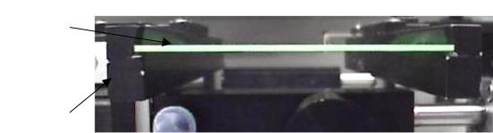
Press and hold the NOZZLE DOWN button. The reflow head will lower itself, slowly. Lower the reflow head until there is no gap between the nozzle and the PCB. See Figure 11. If you need to raise the reflow head up by a slight amount, press the NOZZLE UP button briefly.
When repeating operations using the same PCB and device, the mechanical stop on the left side of the reflow apparatus may be set to ensure repeatability.
The reflow head has a clutch that will engage if the nozzle applies pressure on the PCB or the mechanical stop. This ensures the safety of the PCB and the motor that drives the reflow head.
NOTE: In some instances the space around a component will be insufficient to bring the nozzle into contact with the PCB. Should this occur, select a nozzle with dimensions that
Page 19 of 67
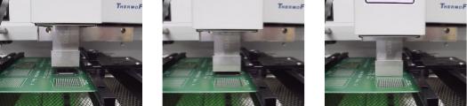
are similar to the component body. For reflow, position the nozzle 1 mm above the component. The time of the reflow cycle may have to be adjusted to insure satisfactory results. A thermo-couple should be used to verify reflow conditions.
Figure 11: Properly Positioned Nozzle in Relation to PCB
6)When the nozzle is properly positioned, press the CYCLE START button. The PREHEAT LED on the Phase Display Panel will light and the reflow cycle will begin.
7)The Phase Display Panel (See Figure 8) will indicate the phase of the reflow cycle (PREHEAT, SOAK, REFLOW and COOLDOWN) and the time for each phase will be counted down on the LCD
Display. An audible alarm will sound seven (7) seconds before the end of the reflow phase.
8)When the reflow cycle is complete, the nozzle will automatically raise and the COOLING FAN will turn on, cooling the soldered component, PCB and nozzle.
9)Do not remove the PCB from the board holder until the COOLING LED has gone off and the OFF LED is lighted.
3-4 Adjusting Airflow
1)The knob on the air flow meter adjusts the air flow. Make sure to match the air flow meter value with the value of FLOW on the LCD Display. The actual air flow will not be changed by the flow value of the display panel.
3-5 Component Removal
1)Component removal is accomplished in the same way as the reflow.
2)When the audible alarm signals 7 seconds before the end of the reflow phase, push the VACUUM button to turn on the vacuum pump.
3)Once the reflow head raises up, remove the component by using the hand held vacuum pick.
4)It is possible to shorten the profile for removals.
Page 20 of 67
4 SELECTING A PROFILE
Please refer to Figure 8 for this section.
1.Using the SELECT button, move the cursor to the PROFILE NO. position.
2.Select a profile by pressing the UP or DOWN buttons. The TF 2000 can store up to 40 profiles. Profile memory locations from 00 to 39 are available. The TF 2000 comes with three profiles loaded (locations 00, 01, and 02). These should be used as baselines when creating profiles. User profiles can be stored in locations 03 through 38. Location 39 is used as a working memory when profiles are downloaded from a PC. See Software section. The profile parameters in use are visible on the LCD display.
5 CREATING AND SAVING PROFILES
Please refer to Figure 8 for this section.
5-1 General Information
The TF 2000 comes with three profiles already installed that should be used as baselines when developing profiles. The profile in memory location 00 is recommended as a starting point for area arrays smaller than 35 mm square. The profile in memory location 01 is recommended for reflowing area arrays 35 mm square and larger. Profile number 02 is essentially the same as profile number 01, but adds a temperature spike (30 °C) from the Bottom Side heater during the reflow phase.
5-2 How to install a profile:
1)Using the SELECT button, move the cursor to the item to be changed.
2)Change the value by pressing the UP or DOWN button.
3)After all values have been set, press the MEMORY button once.
The LED above the MEMORY button will go on.
4)Press the SELECT button to move the cursor to PROFILE NO.
5)Using either the UP or DOWN button, choose a profile memory location (03 through 38) to save the profile into.
6)When the memory location has been selected, press the MEMORY button until the audible signal is heard indicating the profile has been saved to the memory location selected.
7)Once the profile has been saved, the LED lamp will go out.
Page 21 of 67
Loading...