


MBT250
1
MANUAL
OPERATION &
MAINTENANCE
MBT 250 SYSTEMS

Use of this manual
The information contained in this manual will provide the user with the knowledge necessary to
properly operate and maintain the PACE MBT 250 systems. When using your new system in
standard soldering/desoldering operations, you can begin operation quickly by performing the
"Set-Up" and "Quick Start - Basic Operation" procedures detailed on pages 13-19 of this manual.
To fully utilize the features of the system, PACE Strongly recommends that the user read and fully
understand the "Operation" and "Calibration" portions of this manual. The use of these features
is especially important when performing operations which require the use of large or specialized
tips. The "Quick Reference" guide is provided as a convenient reference for day-to-day operation
of the system.
If you encounter any difficulty operating your system, call your local authorized PACE dealer or
contact PACE as shown on page iv of this manual.
1
GENERAL INFORMATION

Introduction
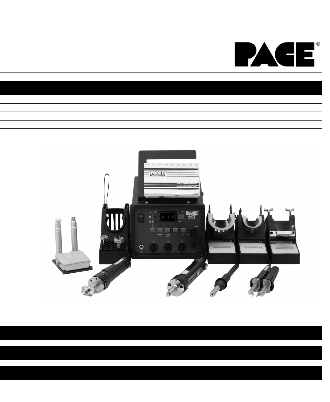
MBT 250 Universal Soldering and Repair Systems provide the user with the power and versatility to remove and
install virtually all SMD and Thru-Hole components. The power source incorporates the highly responsive
SensaTemp (closed-loop) temperature control system which provides up to 182 watts of total power to the three
output channels (see Power Management, Page 12). Microprocessor controlled circuitry allows the user to quickly
configure the system to their requirements and easily recalibrate the system to maintain accuracy and peak
performance. Accessory SensaTemp handpieces (standard & optional) and a wide variety of special use tips,
employing different shapes and sizes, allow the user to remove and replace a wide variety of component
configurations.
Virtually all of today’s specialized handpieces with large SMD tips suffer from a problem in which the actual tip
temperature that the work sees can be more than 55°C (100°F) cooler than the Set Tip Temperature displayed. The
MBT 250 systems feature PACE’s unique Tip & Temperature Selection System with Auto Tip Offset Compensation
which allows the user to Set and Display the True, Correct Tip Temperature for any size and type of tip or
handpiece.
The MBT 250 systems are available in either the 115 VAC, 100 VAC or 230 VAC versions. The 230 VAC version
systems bear the CE Conformity Marking which assures the user that it conforms to all the requirements of council
directive EMC 89/336/EEC. The systems include the power source with a selection of accessories and functional
aids.
PACE uses the following suffix letters on all MBT 250 systems to indicate the specific design configuration.
S - Soldering (PS-90)
D - Desoldering (SX-80)
T - Thermotweez (TT-65)
J - ThermoJet (TJ-70)
P - ThermoPic (TP-65)
2
GENERAL INFORMATION

System Configurations
MBT 250-SD
MBT 250-SDPT
MBT 250E-SD Soft Ground
MBT 250E-SD
MBT 250E-SDPT
MBT 250E-SDPT Soft Ground
8007-0203
8007-0204
8007-0204-01
8007-0206
8007-0207
8007-0207-1
3
Power Source, 115 VAC, 60 Hz
X
X
Power Source, 230 VAC 50 Hz
X
X
X
X
PS-90 Soldering Iron
X
X
X
X
X
X
SX-80 Sodr-X-Tractor
X
X
X
X
X
X
TP-65 ThermoPic Handpiece
X
X
X
TT-65 ThermoTweez Handpiece
X
X
X
PS-90 Tip and Tool Stand
X
X
X
X
X
X
SX-80 Tip and Tool Stand
X
X
X
X
X
X
Tip Maintenance Station
X
X
X
X
X
X
Pace Tip & Tempurature Selection System Kit
X
X
X
X
X
X
System Part Number
GENERAL INFORMATION

SPECIFICATIONS
POWER REQUIREMENTS
MBT 250 - Version operates on 97-127 VAC, 50/60 Hz.
185 Watts, 1.6 Amp max, 100% Duty Cycle, Motor on.
MBT 250E - Version operates on 196-253 VAC, 50 Hz.
212 Watts, 0.92 Amp max, 100% Duty Cycle, Motor on.
PHYSICAL PARAMETERS
Size: 13.5 cm H x 16.5 cm W x 26 cm D (5.3"H x 6.5"W x 10.25"D)
Weight: 4.5 Kg. (10 Lbs.)
VACUUM AND AIR (motor operated systems)
Measurements at front panel AUTO SNAP-VAC and CONTROLLABLE PRESSURE Ports.
Vacuum Rise Time: Evacuates 33 cc (2 cubic inch) volume
to 25 cm Hg. (10 in. Hg.) in 150 ms.
Vacuum: 51 cm Hg. (20 in. Hg.) (nominal)
Pressure: .48 Bar (7 P.S.I.) (nominal MAXIMUM setting)
Air Flow: 9 SLPM (0.32 SCFM)MAXIMUM
TEMPERATURE SPECIFICATIONS
Tip Temperature Range: 38°C to 482°C (100°F to 900°F) nominal (see note).
Digital Readout Resolution: ±1° (°C or °F)
Tip Temperature Stability: ±1.1°C (2°F) at Idle from Set Tip Temperature.
4
GENERAL INFORMATION

EOS/ESD
Tip-To-Ground Resistance: Less than 5 ohms (except on Soft Ground Systems).
AC Leakage: Less than 2 millivolts RMS from 50Hz to 500Hz
(except on Soft Ground Systems).
ENVIRONMENTAL REQUIREMENTS
Ambient Operating Temperature: 0°C to 50°C (32°F to 120°F)
Storage Temperature: -40°C to 100°C (-40°F to 212°F)
Capabilities
All capabilities are dependent upon the use of the appropriate Functional Accessories or Work Aids (refer to Basic
Operation section). Available SensaTemp handpieces and their associated assembly and repair functions are listed
below. An Operations and Maintenance Manual is provided separately with each handpiece which describes the
applications and recommended procedures for that particular tool.
PS-90 Soldering Iron - Provides a wide range of SMD and thru-hole installation and removal capability as well as
unsurpassed thermal performance on heavy, multilayer thru-hole assemblies at safe, lower working temperatures.
A wide variety of 3/16" shank, quick change thru-hole and SMD tips (for chip components, SOTs, SOICs and
other components) are available.
SX-80 Sodr-X-Tractor handpiece - Air handpiece ideal for thru-hole desoldering on extra high mass multilayer
boards. Also ideal for removal of TSOP & TQFP surface mount components and for “Flo” desoldering during
surface mount land preparation.
TT-65 ThermoTweez handpiece - Performs removal of PLCC (J Leaded), LCCC (leadless) and other surface mount
devices.
TP-65 ThermoPik handpiece - Air handpiece performs removal of Flat Pack, QFP & PQFP surface mount devices.
DTP-80 Dual ThermoPik handpiece - Air handpiece performs removal of large Flat Pack, QFP, PQFP & BGA surface
mount devices.
TJ-70 Mini ThermoJet handpiece - Air handpiece. Focused hot air reflow handpiece used for installation of all
types of surface mount devices.
5
NOTE
Actual minimum and maximum Operating Tip Temperatures may vary
depending on handpiece & tip selection.
GENERAL INFORMATION

Parts Identification
Listed below is a description of the system power source parts. Use Figures 1 & 2 as a guide.
1. CH 1 POWER RECEPTACLE - Provides power, tip ground, sensing circuitry and finger switch connection
from MBT system to handpiece connected to Channel 1 (CH 1).
2. CH 2 POWER RECEPTACLE - Provides power, tip ground, sensing circuitry and finger switch connection
from MBT system to handpiece connected to Channel 2 (CH 2).
3. CH 3 POWER RECEPTACLE - Provides power, tip ground, sensing circuitry and finger switch connection
from MBT system to handpiece connected to Channel 3 (CH 3).
4. POWER SWITCH - Turns system ON ("1") and OFF ("0"); controls input power to the system.
5. AUTO SNAP-VAC PORT - Quick connect fitting provides quick-rise vacuum for Sodr-X-Tractor,
ThermoPik and Dual ThermoPik handpieces. Vacuum is present when handpiece finger switch or optional
foot pedal is actuated. Vacuum ceases 1.2 seconds after switch (or foot pedal) released.
6. CONTROLLABLE PRESSURE PORT - Quick connect fitting with adjustable valve which provides
variable air flow for Mini ThermoJet handpiece (in Hot Jet Mode) and Sodr-X-Tractor handpiece. Air
pressure is present when handpiece finger switch or optional foot pedal is actuated. Air pressure ceases
1.2 seconds after switch (or foot pedal) is released.
7. DIGITAL READOUT - Provides a three digit display of the Current Channel (channel with illuminated LED;
CH 1, CH 2 or CH 3 ) temperature information. This includes: Operating Tip Temperature in Temperature
Display Mode (normal operation), Tip Offset Constant in Tip Offset Mode, Set Tip Temperature in Tip Set
Mode and other information in Calibration (CAL) Mode.
8. °F /°C KEY - Selects °F or °C display of Set and Operating Tip Temperatures and Tip Offset Constants.
9. °F LED - Illuminates when Set\ Operating Tip Temperatures and Tip Offset Constants are displayed in °F.
10. °C LED - Illuminates when Set\ Operating Tip Temperatures and Tip Offset Constants are displayed in °C.
11. CH 1 LED - Illuminates when Channel 1 (CH 1) is the “Current Channel” i.e., the channel (with connected
handpiece\tip) whose temperature information is displayed on the digital readout.
12. CH 2 LED - Illuminates when Channel 2 (CH 2) is the “Current Channel” i.e., the channel (with connected
handpiece\tip) whose temperature information is displayed on the digital readout.
13. CH 3 LED - Illuminates when Channel 3 (CH 3) is the “Current Channel” i.e., the channel (with connected
handpiece\tip) whose temperature information is displayed on the digital readout.
14. CH SELECT KEY - Selects the Current Channel (among "Active Channels" i.e., those with a connected
handpiece).
15. TIP SET KEY - Allows the operator to adjust the Set Tip Temperature for the handpiece\tip combination
connected to the Current Channel. Places the system in the Tip Set Mode.
6
GENERAL INFORMATION

16. TIP SET LED - Flashes when TIP SET Key is pressed indicating that the system is in Tip Set Mode.
17. TIP OFFSET KEY - Allows the operator to adjust the Tip Offset Constant for the handpiece connected to
the Current Channel. Places the system in the Tip Offset Mode.
18. TIP OFFSET LED - Flashes when TIP OFFSET Key is pressed indicating that the system is in Tip Offset
Mode. Remains illuminated (not flashing) in Temperature Display Mode (normal operating mode) when a
Tip Offset Constant of greater than "3" for °C ("6" for °F) is entered.
19. SCROLL UP KEY - Increases the Set Tip Temperature (in Tip Set Mode) and the Tip Offset Constant (in
Tip Offset Mode) in one, then ten degree increments. Also used in “CAL” (Calibration) Mode.
20. SCROLL DOWN KEY - Decreases the Set Tip Temperature (in Tip Set Mode) and the Tip Offset Constant
(in Tip Offset Mode) in one then ten degree increments. Also used in “CAL” (Calibration) Mode.
21. EARTH GROUND RECEPTACLE - provides positive earth ground to which a ground cable can be
connected from the workpiece or work surface as part of a static control program.
22 . TIP & TEMPERATURE SELECTION SYSTEM CHART HOLDER - Holds PACE’s Tip & Temperature
Selection System Charts which enable the operator to accurately set and display the true, correct operating
tip temperature for any handpiece\tip configuration.
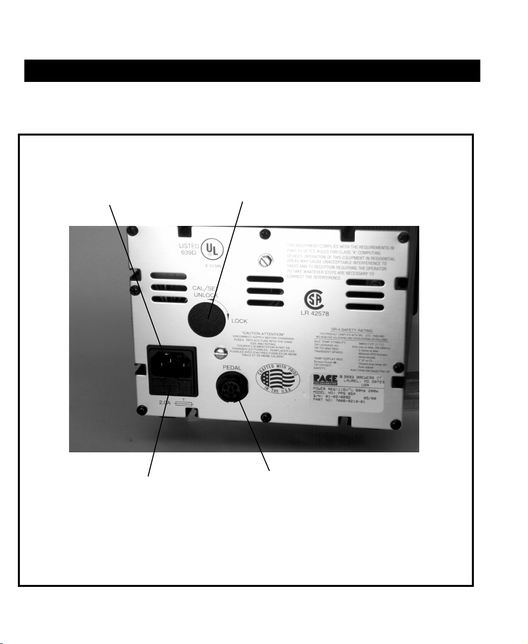
23. AC POWER RECEPTACLE / FUSE HOLDER - Receptacle for providing power to the system from AC
outlet through power cord. Also location of Fuse (F1) which protects system from overcurrent conditions.
24. CAL / SET KEY LOCK (optional) - In the "LOCK" position, Set Tip Temperatures and Tip Offset
Constants cannot be changed. In addition, the system cannot be put into "CAL" Mode. In the
"UNLOCK" position, all system functions operate normally.
25. FOOT PEDAL RECEPTACLE - Input for Foot Pedal (optional) which actuates vacuum or pressure to the
air-operated handpieces.
26. AIR HOSE FITTING ("V" systems only) - Fitting for connection of house air supply to power source air
venturi assembly.
26. FUSE - Provides overload protection for system.
7
GENERAL INFORMATION
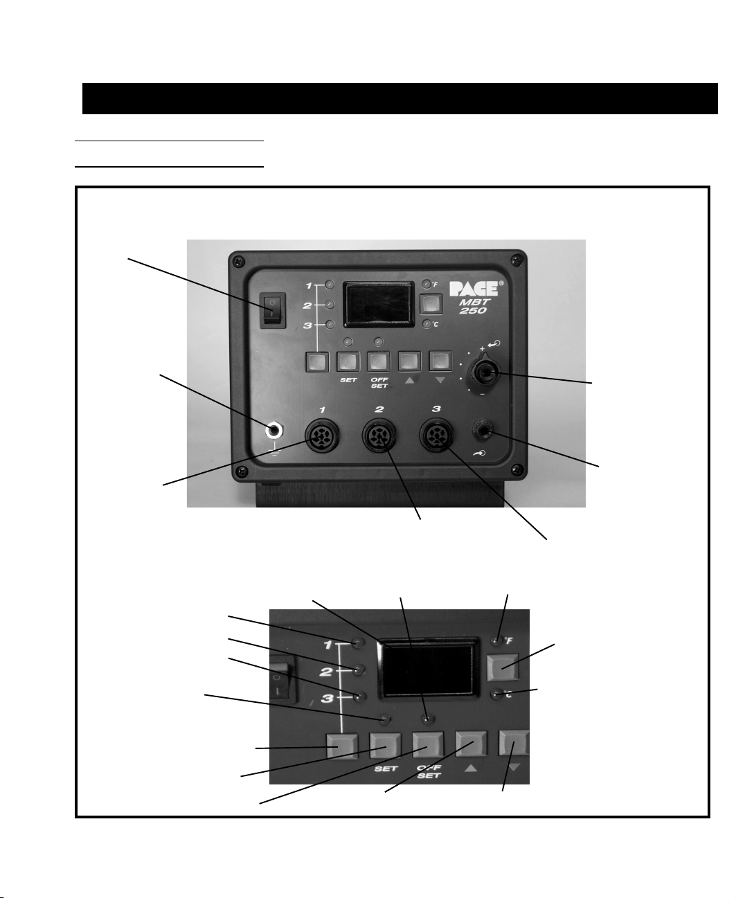
Figure 1. Parts Identification, Front View
Parts Identification (Con't)
Power
Switch
Earth
Ground
Receptacle
CH1
Power
Receptacle
Controllable
Pressure
Port
AUTO
SNAP-VAC
Port
CH3
Power
Receptacle
CH2
Power
Receptacle
Digital
Readout
Tip Offset
LED
°F LED
°F / °C KEY
CH1 LED
CH2 LED
CH3 LED
Tip Set
LED
CH Select Key
Tip Set Key
Tip Offset Key Scroll Up Key Scroll Down Key
°C LED
8
GENERAL INFORMATION
10
Figure 2. Parts Identification, Rear View
CAL/SET
Key Lock
(Optional)
AC Power
Receptacle/
Fuse Holder
Fuse
Foot
Pedal
Receptacle
9
GENERAL INFORMATION

11
Power Management
IMPORTANT
POWER MANAGEMENT NOTE
The MBT 250 systems will perform nominally when using any combination of handpieces with a total of 197
Watts or less. When using 2 TT-65 ThermoTweez or DTP-80 Dual ThermoPik handpieces on the system, PACE
recommends that the operator leave the third Power Receptacle vacant to insure optimum performance.
MAX. POWER
1. PS-90 Soldering Iron .............................................................................. 51 Watts
2. SX-80 Sodr-X-Tractor handpiece (air handpiece) ................................. 48 Watts
3. TT-65 ThermoTweez handpiece ............................................................74 Watts (37 Watts each heater)
4. TJ-70 Mini ThermoJet handpiece (air handpiece) ................................. 75 Watts
5. TP-65 ThermoPik handpiece (air handpiece) ......................................... 43 Watts
6. DTP-80 Dual ThermoPik handpiece ...................................................... 74 Watts (37 Watts each heater)
NOTE
Although 2 air handpieces can be powered up and idle at set temperature
simultaneously, only one may have its air hose attached to the unit and operate
at a time. In addition, any other combination of handpieces with a total of 197
Watts or less will perform nominally (add the Wattage designations on the heater
flange(s) of each handpiece to calculate total Watts). For example, you may want
to have two or more PS-90 Soldering Irons with different tips powered up at one
time for convenience.
PACE recommends the purchase of a ST series system power source which can be used in conjunction
with the MBT 250 system. For example, you may want to power a TJ-70 Mini ThermoJet, PS-90 Soldering
Iron and a SX-80 Sodr-X-Tractor handpiece on your MBT 250, and power a TT-65 ThermoTweez handpiece
on your ST-TT system to suit your particular application.
If you require assistance in the use of this product, contact your local authorized PACE dealer or
PACE directly as shown on page iv of this manual.
10
GENERAL INFORMATION

12
The purpose of this "SAFETY" section is to inform users of the heading guidelines used in this manual to indicate
special Notes, Cautions, Warnings or Dangers. Also included are recommended precautions which must be
observed when operating or servicing this product.
Heading Guidelines
PACE adheres to the following Heading Guidelines (based on OSHA guidelines) when listing special information or
precautions to be taken. Especially important are all procedures and practices which, if not strictly observed, could
result in injury or loss of life.
These "NOTES", "CAUTIONS","WARNINGS" and "DANGERS" are inserted in this manual whenever deemed
necessary. They appear in a blocked off form with double outline and a shaded background to highlight the
information as shown below.
NOTE
XXXXXXXXXXXXXXXXXXXXXXXXXXXXXXXXXXXXXXXXXXXXXXXXXX
NOTE
Used to indicate a statement of company recommendation or policy. The message may relate directly or indirectly
to the safety of personnel or protection of property. NOTE is not associated directly with a hazard or hazardous
situation and is not used in place of "CAUTION", "WARNING" or "DANGER".
CAUTION
Used to indicate a hazardous situation which may result in minor or moderate injury. May also be used to alert
personnel to conditions, procedures and practices which, if not observed, could result in damage to or destruction
of the product or other equipment.
WARNING
Used to define additional information that if not closely followed might result in serious damage to equipment and
represent a potential for serious personnel injury.
DANGER
Defines additional information that if not closely followed might result in severe personnel injury or death. Danger
is not used for property damage unless personal injury risk is present.
11
SAFETY

13
Precautions
The following are general safety precautions which personnel must understand and follow when using or servicing
this product. These precautions may or may not be included elsewhere in this manual.
CAUTIONS
1. Handpiece heaters and installed tips are hot when handpiece is powered on. DO NOT touch either the
heater or tip. Severe burns may result! Always store handpiece in the appropriate Tip & Tool Stand
when not in use.
2. Always use this system in a well ventilated area. A fume extraction system such as those available from
PACE are highly recommended to help protect personnel from solder flux fumes.
3. Exercise proper precautions when using materials (e.g., solder paste). Refer to the Material Safety Data
Sheet (MSDS) supplied with each chemical and adhere to all safety precautions recommended by the
manufacturer.
NOTES
Refer to the MBT 250, Service Manual (P/N 5050-0352) whenever service is required.
To insure continued peak performance, use genuine PACE replacement parts.
12
SAFETY

14
Safety Guidelines, English Language
The following are safety precautions which personnel must understand and follow when using or servicing this
product.
1. POTENTIAL SHOCK HAZARD - Repair procedures on PACE products should be performed by
Qualified Service Personnel only. Line voltage parts may be exposed when the equipment is
disassembled. Service personnel must avoid contact with these parts when troubleshooting the
product.
2. To prevent personnel injury, adhere to safety guidelines in accordance with OSHA and other applicable
safety standards.
3. SensaTemp handpiece heaters and installed tips are hot when the handpiece is powered on and for a
period of time after power off. DO NOT touch either the heater or the tip. Severe burns may result.
4. PACE Tip & Tool Stands and handpiece cubbies are designed specifically for use with the associated
handpiece and houses it in a manner which protects the user from accidental burns. Always store the
handpiece in its holder. Be sure to place the handpiece in its holder after use and allow to cool before
storing.
5. Always use PACE systems in a well ventilated area. A fume extraction system such as those available
from PACE are highly recommended to help protect personnel from solder flux fumes.
6. Exercise proper precautions when using chemicals (e.g., solder paste). Refer to the Material Safety Data
Sheet (MSDS) supplied with each chemical and adhere to all safety precautions recommended by the
manufacturer.
Sicherheit Korrekturlinien, Deutsche Sprache
Die nachfolgenden Sicherheitsvorschriften sollten vom Bedien- un Servicepersonal verstanden und befolgt
werden.
1. Entladung spannungsfuehrender Teile - Reparaturen an PACE Produkten sollten nur von qualifizierten
Personal durchgefuehrt werden. Spannungsfuehrende Teile koennen sich bei gezogenen Netzstecker
entladen. Servicepersonal muss den Kontakt dieser Teile vermeiden.
2. Um moegliche Gefahren fuer Personen auszuschliessen, muessen alle Sicherheitsvorschriften in
Uebereinstimmung mit OSHA und anderen anwendbaren Sicherheitsstandards eingehalten werden.
13
SAFETY

15
3. Angeschlossene SensaTemp Heizelemente von Handwerkzeugen und installierte Loetspitzen sind
heiss wenn das System eingeschaltet ist oder erst vor kurzer Zeit ausgeschaltet wurde. Heizelement
und Loetspitze nicht beruehren. Verbrennungsgefahr.
4. PACE Tip & Tool und andere Handwerkzeugablagen sind so konstruiert, dass ein versehentliches
Beruehren des dazugehoerendes Handwerkzeuges vermieden wird. Bewahren Sie das Handwerkzeug
nach Gebrauch stets in der Ablage auf. Bevor das Handwerkzeug an einem anderen Ort gelagert werden
muss, lassen Sie es in der Werkzeugablage vollstaendig abkuehlen.
5. Benutze PACE Systeme nur in gut beluefteten Raeumen. Ein Loetrauchabsaugsystem, wie es z.B. von
PACE erhaeltlich ist, hilft Bedienpersonen von den Gefahren von Loetrauch zu schuetzen.
6. Wenn Chemikalien (z.B.: Lotpaste) verwendet werden, muessen alle die in den Sicherheitsdatenblaettern
des Herstellers ausgewiesenen Sicherheitsvorschriften eingehalten werden.
SICHERHEITDIRECTIVES DE SÉCURITÉ,
Les précautions suivantes, sont celles que le personnel doit comprendre et suivre lorsqu'il utilise, effectue la
maintenance ou se sert d'un produit PACE.
1. Danger potentiel de choc èlectrique - Les procédures de réparation sur les produits PACE doivent être
effectuées seulement par du personnel qualifié. Des parties de l'équipement désassemblées peuvent
être sous tension. Le personnel de maintenance doit éviter tout contact avec ces parties en réparant le
produit.
2. Pour prévenir tout préjudice, le personnel adhère au guide de sécurité en accord avec OSHA
(équivalent à des normes françaises de sécurité) et d'autres standards de sécurité applicable.
3. La mise sous tension des outils SensaTemp comporte des éléments chauffants (buse). Ces derniers,
gardent la chaleur même après la mise hors tension pendant un certain temps. Ne pas toucher les
parties chaudes aux extrémités des outils. Des brûlures sévères peuvent en résulter.
4. Les outils PACE et leurs pannes ainsi que le support sont dessinés de manière spécifique afin de
protéger l'utilisateur/opérateur de brûlures accidentelles. Reposer toujours les outils après chaque
utilisation dans leurs étuis/supports afin de permettre leur refroidissement.
5. Utiliser toujours les stations Pace dans unlieu bien ventilé. Des extracteurs de fumée Pace sont
hautement recommandés pour protéger votre personnel des vapeurs de soudure/flux.
6. Prenez les mesures nécessaires quand vous utilisez des produits (ex: solder paste) chimiques. Reportez-
vous au document (fiche technique/sécurité) du fabricant fourni avec chaque produit. Respectez toutes
les procédures de sécurité recommandées par le constructeur.
Directives de Sécurité, Française Langue
14
SAFETY

16
Misure di Sicurezza, Italiana Lingua
Le seguenti instruzioni sono misure di sicurezza che il personale deve comprendere e seguire quando utilizza o
ripara I prodotti PACE.
1. EVENTUALI RISCHI DI SHOCK ELETTRICO- Si consiglia di far eseguire le operazioni di riparazione
dei prodotti PACE, da un servizio di personale qualificato. Quando la stazione non é assemblata le parti
sottoposte alla tensione di linea potrebbero essere scoperte. Il personale deve evitare il contatto con
queste parti durante manutenzione del prodotto.
2. Per evitare eventuali pericoli al personale, attenersi alle norme di sicurezza previste dalla guida, in conformitá
all’OSHA e agli altri Standard di Sicurezza applicabili.
3. Le resistenze PACE Sensatemp e le punte installate sono calde quando la stazione é accesa e per un
periodo successivo allo spegnimento. Non toccare la resistenza e la punta. Puó comportare gravi
ustioni.
4. I supporti PACE sono specificamente costruiti insieme alla corrispondente impugnatura e progettati per
un uso che protegge gli utenti da ustioni accidentali. Mettere sempre l’impugnatura nel propio supporto
dopo l’utilizzo e lasciarla raffredare prima di riporla.
5. Utilizzare sempre I stazioni PACE in una zona be aerata per proteggere il personale dai fumi. É fortemente
raccomandato un sistema di aspirazione (dei fumi) come quello disposta dalla PACE.
6. Usare precauzioni quando si utilizzano sotanze chimiche (es. Pasta di stagno). Fare riferimento al
Material Safety Data Sheet (MSDS) fornita con ogni sostanza chimica e seguire tutte le misure di
sicurezza raccomandate dal fabbricante.
15
SAFETY

17
2. Para evitar danos pessoais, siga as normas de segurança OSHA ou outras normas aplicáveis.
3. Resistencias de aquecimento dos ferros e as pontas instaladas estão quentesquando o ferro está
alimentado, e mesmo durante algum tempo após ser desligado. NUNCA TOCAR nem na resistencia de
aquecimento nem na ponta. Pode resultar em queimaduras severas.
4. Os suportes para pontas e ferros da PACE, foram concebidos para uso especifico, e para proteger o
operador de queimaduras acidentais. Coloque sempre os ferros nos respectivos suportes. Tenha a
certeza de colocar sempre o ferro no respectivo suporte após cada utilização e deixe-o arrefecer antes de
o guardar.
5. Utilize sempre os sistemas da PACE em locais bem ventilados. Um Sistema de extracção de fumos, como os
Sistemas disponiveis na PACE, são altamente recomendados para a protecção dos utilizadores contra os fumos
produzidos pela solda e fluxo.
6. Tenha precauções apropriadas ao utilizar produtos quimicos (ex. pasta de soldar). Lêr sempre atentamente os
normas de segurança fornecidas com cada produto químico e siga sempre todas as precauções de segurança
recomendadas pelo fabricante.
Guias de Consulta de Seguridad, Espãnol Lenguaje
Lo siguiente es precauciones de seguridad que el personal debe entender y debe seguir al usar o reparar productos
de PACE.
1. RIESGO de SHOCK POTENCIAL - Los procedimientos de la Reparación en productos de PACE sólo
deben ser realizados por Personal de Servicio Calificado. Pueden exponerse partes de voltaje de línea
cuando el equipo se desmonta. El personal de servicio debe evitar contacto con estas partes al arreglar el
producto.
2. Para prevenir lesión del personal, adhiera a las reglas de seguridad de acuerdo con OSHA y otras
normas de seguridad aplicables.
16
Guidelines de Segurança, Portuguese Lingua
Segeum-se precauções de segurança que os operadores devem compreender e seguir ao utilizar ou reparar
produtos PACE.
1. Perigo de choque eléctrico - Os procedimentos de reparação em produtos PACE, devem ser apenas
efectuados por pessoal qualificado. Linhas de alimentação podem ficar expostas ao desmontar o
equipamento. Pessoal de reparação deve evitar o contacto com essas partes ao reparar o produto.
SAFETY

18
3. Las herramientas SensaTemp tienen sus calentadores y las puntas instaladas calientes cuando la
herramienta esta encendida y por un periodo de tiempo después de apagar el equipo. No toque el
calentador o la punta. Las quemaduras severas pueden resultar.
4. El Soporte de punta y Herramienta PACE se diseñan específicamente para el uso con las herramientas
asociadas y las almacena de una manera que protege al usuario de las quemaduras accidentales.
Siempre guarde la herramienta en su soporte. Esté seguro de poner la herramienta en su soporte
después del uso y permita que la herramienta enfríe antes de guardar.
5. Siempre use sistemas de PACE en una área bien ventilada. Un sistema de extraccíon de humo como
esos disponibles de PACE se recomiendan para ayudar a protejer al personal contra los humos de flujo
de soldadura.
6. Ejercicie las precauciones apropiadas al usar químicos (ej., pasta de la soldadura). Refiérase a la Hoja de Datos de
Seguridad de Material (MSDS) proporcionadó con cada químico y adhiere a todas las precauciones de seguridad
recomendadas por el fabricante.
Säkerhetsföreskrifter, Svenska
Följande säkerhetsföreskrifter måste förstås och följas av personal som använder eller utför service på PACE
produkter.
1. RISK FÖR STRÖMSTÖT - Service / Reparation av PACE produkter får endast utföras av aktoriserad
service personal. Strömförande delar kan kommas åt när produkten är isärplockad. Iaktag aksamhet när
felsökning görs för att undvika strömstötar.
2. För att undvika personskada rekommenderas att OSHA eller andra liknande arbetssäkerhets standarder
följs.
3. SensaTemp verktygselement och installerade spetsar är heta när strömmen är påslagen och en tid efter
att strömmen slagits av. RÖR EJ element eller spets. Risk för brännskador!
4. PACE Spets och Verktygshållare är speciellt utformade för att passa PACE respektive verktyg så att
risken för brännskador kan undvikas. När verktyget ej används bör det alltid förvaras i sin hållare.
5. Tillse att ventilationen är god där PACE System används. Ett lödröksutsug system som t.ex. PACE
tillhandahåller rekommenderas för att skydda användaren för giftig lödrök.
6. Tillse att gällande säkerhetsföreskrifter följs vid användning av kemikalier, t.ex. lodpasta.Se
säkerhetsdatabladen som medföljer kemikalierna och följ de rekommenderade säkerhetsföreskrifterna
från respektive tillverkare. Säkerhetsföreskrifter, Svenska
17
SAFETY
 Loading...