


Operation and Maintenance Manual for ST 100 Power Sources
P/N 5050-00557 REV. A 082006
This manual applies to:
|
Model |
|
|
PACE Power |
|
System Part Number |
|
|
|
Supply Number |
|
|
|||
|
|
|
|
|
|
||
|
ST 100 |
|
|
7008-0296-01 |
|
8007 - 0524 |
|
|
|
|
|
8007 - 0525 |
|
||
|
|
|
|
|
|
|
|
|
ST 100E |
|
|
7008-0296-02 |
|
8007 - 0526 |
|
|
|
|
|
8007 - 0527 |
|
||
|
|
|
|
|
|
|
|
General Information |
|
|
|
|
|
||
Introduction................................................................................................................ |
|
|
|
2 |
|||
Power Source Requirements..................................................................................... |
2 |
||||||
Temperature Specifications ....................................................................................... |
|
|
2 |
||||
EOS/ESD Specifications............................................................................................ |
|
|
|
2 |
|||
Power Supply Features ............................................................................................. |
|
|
|
3 |
|||
Safety |
|
|
|
|
|
||
Safety Guidelines....................................................................................................... |
|
|
|
4 |
|||
System Set-Up |
|
|
|
|
|
||
Tip & Tool Stand Mounting Option (PS-90 & TT-65) |
..................................................4 |
||||||
Handpiece Connection .............................................................................................. |
|
|
|
4 |
|||
System Power Up...................................................................................................... |
|
|
|
5 |
|||
Operation ............................................................................................................................ |
|
|
|
5 |
|||
LED Operation........................................................................................................... |
|
|
|
5 |
|||
LCD Display............................................................................................................... |
|
|
|
5 |
|||
Temperature Setback & Auto-Off Modes................................................................... |
6 |
||||||
Customizing Your System ................................................................................................. |
|
|
|
7 |
|||
Introduction ............................................................................................................ |
|
|
|
7 |
|||
Entering Set-Up Mode............................................................................................ |
|
|
|
7 |
|||
Password ............................................................................................................... |
|
|
|
7 |
|||
Temperature Scale................................................................................................. |
|
|
|
7 |
|||
Temperature Limits ................................................................................................ |
|
|
|
7 |
|||
Temperature Setback............................................................................................. |
|
|
|
8 |
|||
Auto Off.................................................................................................................. |
|
|
|
8 |
|||
Scan Mode............................................................................................................. |
|
|
|
8 |
|||
Scan Mode Timer................................................................................................... |
|
|
|
8 |
|||
Back Light Adjustment ........................................................................................... |
|
|
|
8 |
|||
Exiting Set-Up Mode .............................................................................................. |
|
|
|
9 |
|||
Default Factory Settings......................................................................................... |
|
|
|
9 |
|||
System Calibration & Greeting |
..................................................................................... |
|
10 |
||||
Corrective Maintenance ................................................................................................ |
|
|
|
11 |
|||
Spare Parts..................................................................................................................... |
|
|
|
11 |
|||
Service............................................................................................................................ |
|
|
|
11 |
|||
PACE LIMITED WARRANTY STATEMENT................................................................... |
12 |
||||||

General Information
Introduction
Thank you for purchasing an ST 100 system featuring IntelliHeat™. This manual will provide you with the information necessary to properly set up, operate, and maintain your system. Please read this manual thoroughly before using the system. IntelliHeat™ is the combination of THC (Tip Heater Cartridge) and SensaTemp handpieces into one system. The system recognizes either handpiece individually and automatically adjusts the menu driving controls for each handpiece. The 230 VAC version system bears the CE Conformity Marking, which assures the user that it conforms to EMC 89/336/EEC. All models featured in this manual are lead free compatible and comply with RoHS and WEEE directives.
Power Source Requirements
Domestic Model
ST 100 Operates on 97-127 VAC, 50/60Hz, 90 Watts maximum at 115 VAC, 60Hz
Export Model
ST 100E Operates on 197-253 VAC 50/60Hz, 90 Watts maximum at 230 VAC, 50Hz
Temperature Specifications (All Models)
Tip Heater Cartridge Handpiece Tip Temperature Range: 205 to 455°C (400 to 850°F) nominal. SensaTemp Handpieces Tip Temperature Range: 37 to 482°C (100 to 900°F) nominal.
Digital Display Resolution: ±5° (°C or °F)
Tip Temperature Stability: ±1.1°C (2°F) at Idle from Set Tip Temperature. Temperature Accuracy: Meets or exceeds ANSI JSTD 001
EOS/ESD Specifications (All Models)
Tip-To-Ground Resistance: Less than 2 ohms.
AC Leakage: Less than 2 millivolts RMS from 50Hz to 100MHz.
Transient Level: Less than 500mV peak, out to 100MHz.
©2006 PACE Inc., Annapolis Junction, Maryland All Rights Reserved |
Page 2 of 12 |

G
C
F
 D
D
B
 A
A
 I
I
H
J
|
Feature |
Description |
|
A |
Power switch |
On /off control of power supply. |
|
B |
Handpiece Receptacle |
Front panel connection of handpiece. |
|
C |
Program button |
For access and confirmation of program menu functions. |
|
D |
Up arrow button |
Increase set temperature and scroll through program menu functions. |
|
E |
Down arrow button |
Decrease set temperature and scroll through program menu functions. |
|
F |
Digital control LCD |
Indicates status of power supply. |
|
G |
Digital display |
Displays temperature setting and menu functions. |
|
H |
Ground jack |
For ground system to static safe work area. |
|
I |
ISB connections |
Connection for Instant Set Back cubby. |
|
J |
Power inlet with fuse |
Connection for IEC power cord and fuse replacement. |
|
©2006 PACE Inc., Annapolis Junction, Maryland All Rights Reserved |
Page 3 of 12 |
||
Safety Guidelines
The following are safety precautions that personnel must understand and follow when using or servicing this product.
1.POTENTIAL SHOCK HAZARD - Repair procedures on PACE products should be performed by Qualified Service Personnel only. Line voltage parts may be exposed when the equipment is disassembled. Service personnel must avoid contact with these parts when troubleshooting the product.
2.All handpiece heaters and installed tips are hot when the handpiece is powered on and for a period of time after power off. DO NOT touch either the heater or the tip. Severe burns may result.
3.PACE Tip & Tool Stands and handpiece cubbies are designed specifically for use with the associated handpiece and houses it in a manner that protects the user from accidental burns. Always store the handpiece in its holder. Be sure to place the handpiece in its holder after use and allow heater / tip to cool before storing.
4.Always use PACE systems in a well ventilated area. A fume extraction system such as those available from PACE are highly, recommended to protect personnel from solder & flux fumes.
5.Exercise proper precautions when using chemicals (e.g., solder paste). Refer to the Material Safety Data Sheet (MSDS) supplied with each chemical and adhere to all safety precautions recommended by the manufacturer.
System Set-Up
Set up the IntelliHeat™ system using the following steps.
1. Store the shipping container in a convenient location. Reuse of these containers will prevent damage if you store or ship your system.
2. Place the Power Switch in the “OFF” or “0” position.
Mounting Options
1. The power supply should be placed directly on a STABLE workbench or work surface.
Tip & Tool Stand Mounting Option (For PS-90, and TT-65)
Some Tip & Tool Stands can be mounted to the power source. To attach the stand to the power source:
1.Insert the 2 large hex head Mounting Screws (head first) into the “T” slot on the side of the power source case as shown.
2.Place the Tip & Tool Stand beside the power source. Insert ends of the 2 Mounting Screws into the 2 Tip & Tool Stand mounting holes as shown.
3.Install a Thumb Nut onto the end of each Mounting Screw and tighten Thumb Nuts.
4.Place the handpiece into its Tip & Tool Stand.
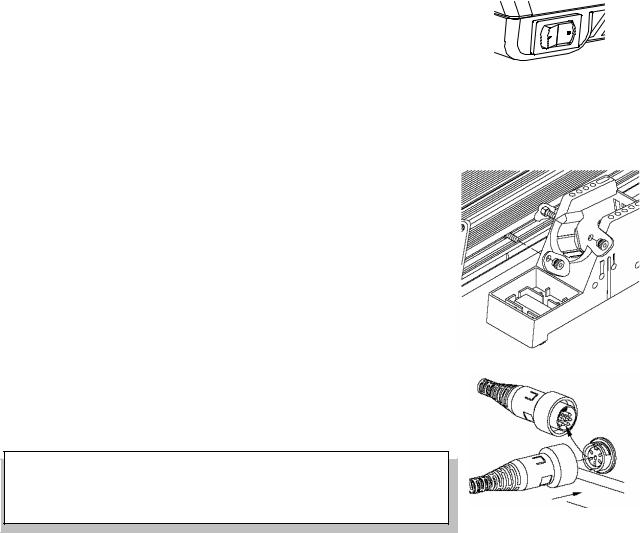
Handpiece Connection - Connect the handpiece connector plug into the Power Receptacle in the following manner.
1.Align guide on connector with slot on power receptacle.
2.Insert connector into power receptacle.
3.Turn the connector housing clockwise to lock in place.
NOTE
IntelliHeat systems are designed for use with PACE handpieces with blue power connectors. Existing, older “black” connector handpieces can be used by purchasing the optional adapter (P/N 6993-0278-P1).
©2006 PACE Inc., Annapolis Junction, Maryland All Rights Reserved |
Page 4 of 12 |
 Loading...