


DC700X

BRINGING TECHNOLOGY HOME
www.pace.com
OPERATOR’S MANUAL
Pace DC700X

1
CONTENTS
This product incorporates copyright protection technology that is protected by
U.S. patents and other intellectual property rights. Use of this copyright protection
technology must be authorized by Macrovision, and is intended for home and other
limited pay-per-view uses only unless otherwise authorized by Macrovision. Reverse
engineering or disassembly is prohibited.
This manual describes some on-screen displays such as menus.
These may change in the future, if the set-top’s software is
updated over the cable. However, the way that you use the
menus will remain similar to the way described in this manual.
SAFETY INFORMATION .............................................................................................2
REAR PANEL ..............................................................................................................8
CONNECTING THE EQUIPMENT .............................................................................10
Connecting the power cord to your set-top ........................................................14
Connecting equipment to the wall AC outlets ....................................................14
OPERATING YOUR SET-TOP ....................................................................................15
Turning your set-top on and off..........................................................................15
Lightning storms ...............................................................................................16
Using your remote control .................................................................................16
Displaying a picture on your HDTV screen ........................................................16
Your set-top’s front panel ...................................................................................17
Adding digital video recorder (DVR) functionality ..............................................18
Using the external hard disk for DVR functions ..................................................19
Using Zoom to change the picture .....................................................................20
SETTING UP SUBTITLES .........................................................................................21
MAKING USER SETTINGS .......................................................................................22
About User Settings ...........................................................................................22
About the TV Aspect Ratio .................................................................................23
About TV Display Capability (resolution settings) ..............................................24
Setting Auto Pillarbox ........................................................................................26
Making Closed Caption Settings .......................................................................28
Making Front-Panel Settings .............................................................................29
Setting Hard Disk Sleep Mode ...........................................................................30
Making HDMI Settings ......................................................................................31
Removing the User Settings menus ...................................................................31
Restoring the factory default settings .................................................................32
USING THE SETUP MENUS .....................................................................................34
SOLVING PROBLEMS ..............................................................................................35
TERMS AND CONDITIONS FOR USE OF SOFTWARE (“TERMS”)............................38
Manufactured under license from Dolby Laboratories.
Dolby and the double-D symbol are trademarks of Dolby Laboratories.
HDMI, the HDMI Logo and High-Definition Multimedia Interface are trademarks or
registered trademarks of HDMI Licensing LLC.
Other trademarks listed herein are the property of their respective owners.
© 2009 Pace plc.
All rights reserved.
Pace and are trademarks and/or registered trademarks of Pace plc
2
SAFETY INFORMATION
This digital set-top has been manufactured and tested with your safety in
mind. However, improper use can result in potential electric shock or fire
hazards. To avoid defeating the safeguards that have been built into your
set-top, please observe the precautions discussed in this document.
To reduce the risk of fire or electric shock, do not expose this set-top to rain
or moisture.
On the rear panel of your set-top there is a tamper-evident label that states
‘Warranty void if broken or removed’.
Installation
The installation of your set-top should be carried out by a qualified installer
and should conform to local codes.
Note to the installer
This reminder is provided to call the attention of the cable-TV-system
installer to Section 820 of the National Electrical Code (USA), which
provides guidelines for proper grounding and, in particular, specifies
that the cable ground shall be connected to the grounding system of the
building, as close to the point of cable entry as is practical.
Service address:
Pace Americas Inc.
3701 FAU Boulevard, Suite 200, Boca Raton, Florida 33431 U.S.A.
Other warnings
To reduce the risk of electric shock, do not remove the cover of your set-top.
There are no user-serviceable parts inside it.
Do not perform any servicing unless you are qualified to do so. Refer all
servicing to qualified service personnel. Servicing the set-top yourself will
invalidate the warranty.
The lightning flash with arrowhead symbol, within a triangle,
is intended to alert you to the presence of uninsulated
“dangerous” voltages within your set-top’s enclosure that may
be of sufficient magnitude to constitute a risk of electric shock
to persons.
The exclamation point within a triangle is intended to alert
you to the presence of important instructions in the literature
accompanying your set-top.
Warnings on your set-top
RISK OF ELE CTRIC SHOCK
DO NOT OPEN
CAUTION
WHEN SERVICING ONLY USE
IDENTICAL REPLACEMENT PARTS
CAUTION

3
IMPORTANT SAFETY INSTRUCTIONS
Before you install or use the apparatus, you must read and
understand these Important Safety Instructions.
At all times when using the apparatus you must follow these
Important Safety Instructions to reduce the risk of fire, electrical
shock and injury to persons.
1. Read these instructions.
2. Keep these instructions.
3. Heed all warnings.
4. Follow all instructions.
5. Do not use this apparatus near water.
6. Clean only with dry cloth.
7. Do not block any ventilation openings. Install in accordance
with the manufacturer’s instructions.
8. Do not install near any heat sources such as radiators, heat
registers, stoves, or other apparatus (including amplifiers) that
produce heat.
9. Do not defeat the safety purpose of the polarized or grounding-type
plug. A polarized plug has two blades with one wider than the
other. A grounding type plug has two blades and a third grounding
prong. The wide blade or the third prong are provided for your
safety. If the provided plug does not fit into the outlet, consult an
electrician for replacement of the obsolete outlet.
10. Protect the power cord from being walked on or pinched
particularly at plugs, convenience receptacles, and the point
where they exit from the apparatus.
11. Only use attachments/accessories specified by the
manufacturer.
12. Use only with the cart, stand, tripod, bracket, or table specified
by the manufacturer, or sold with the apparatus. When a cart is
used, use caution when moving the cart/apparatus combination
to avoid injury from tip-over.
13. Unplug this apparatus during lightning storms or when unused
for long periods of time.
14. Refer all servicing to qualified service personnel. Servicing is
required when the apparatus has been damaged in any way,
such as power-supply cord or plug is damaged, liquid has been
spilled or objects have fallen into the apparatus, the apparatus
has been exposed to rain or moisture, does not operate
normally, or has been dropped.
4
SAFETY INFORMATION (cont.)
In addition to the Important Safety Instructions, please read the Safety
Information below.
Power sources
The model number, serial number, and electrical rating of this set-top are on
a label on its base.
You must operate your set-top only from the type of power source indicated
on the marking label. If you are not sure of the type of power supply to
your home, consult your dealer or local power company. If you move your
set-top between locations at different temperatures, allow it to reach room
temperature before you apply power to it.
Overloading
Do not overload wall AC outlets, extension cords or other power outlets as
this can result in a risk of fire or electric shock.
Lightning
For added protection for your set-top during a lightning storm, or when
it is left unattended and unused for long periods of time, disconnect the
cable system from your set-top. See also item 13 in the Important Safety
Instructions.
Ambient temperature
The operating temperature range of your set-top is 32-104°F. If the ambient
temperature around your set-top falls outside this range, you must correct
this in order for your set-top to work correctly and safely. For example, if the
temperature is too high, make sure there is sufficient ventilation (see below)
and that your set-top is not directly on top of or underneath other equipment.
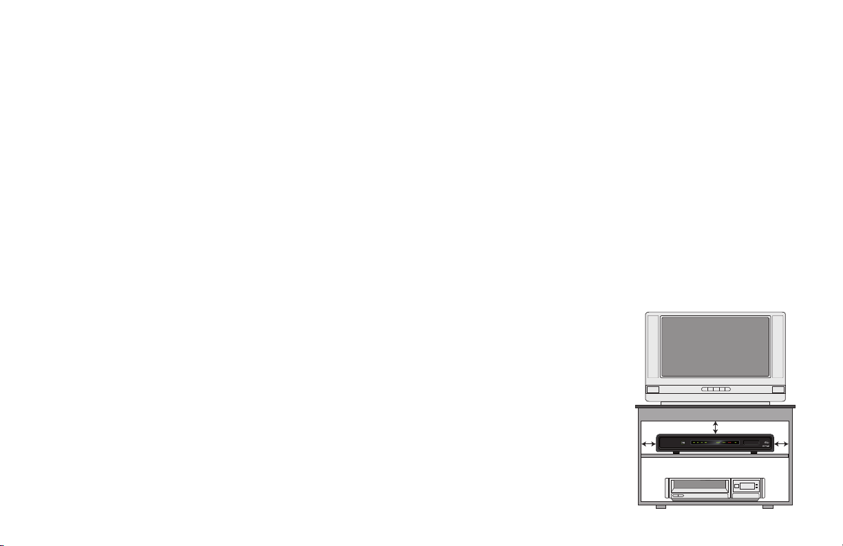
Ventilation
Slots and openings in the casing of your set-top are provided for ventilation,
to ensure reliable operation of your set-top and to protect it from overheating.
• Neverblocktheventilationopeningsbyplacingyourset-toponabed,
sofa, rug, or other similar surface. Place it on a hard, flat surface.
• Nevercovertheventilationopeningswithitemssuchasnewspapers,
table-cloths, or curtains.
• Youcanplaceyourset-topnearotherconsumerelectronicsdevices,such
as stereo amplifiers or televisions, but you must not place it directly on
top or underneath them.
• Donotplaceyourset-topinabuilt-
in installation such as a bookcase
or rack unless proper ventilation is
provided and you have adhered to
the manufacturer’s instructions.
• Maintain a minimum
distance of three inches
around your set-top for
sufficient ventilation.
See also item 7 in the Important Safety
Instructions.
3 in.
3 in.3 in.

5
SAFETY INFORMATION (cont.)
Water and moisture
Do not expose your set-top to rain or moisture, dripping or splashing, and
ensure that no objects filled with liquids, such as vases, are placed on your
set-top. See also item 5 in the Important Safety Instructions.
Entry of objects and liquids
Never push objects of any kind into your set-top through openings as they
may touch dangerous voltage points or short-out parts that could result in
fire or electric shock. Never spill liquid of any kind on your set-top.
Transporting
Move the combination of set-top and cart with care. Quick stops, excessive
force and uneven surfaces may cause the combination of set-top and cart to
overturn. See also item 12 in the Important Safety Instructions.
Placement and mounting
Do not place your set-top on an unstable or uneven surface. Your set-top
may fall, causing serious injury to a child or adult and serious damage to
your set-top. If you mount your set-top, for example to a wall or ceiling,
follow the manufacturer’s instructions and use a mounting accessory
recommended by the manufacturer. See also item 12 in the Important Safety
Instructions.
Risk of fire or scorching
Never place naked flame sources, such as lighted candles, on or adjacent to
your set-top.
Replacement parts
When replacement parts are required, be sure that the service technician has
used replacement parts specified by the manufacturer or that have the same
characteristics as the original part. Unauthorized substitutions may result in
fire, electric shock or other hazards. See also item 14 in the Important Safety
Instructions.
Safety check
Upon completion of any servicing or repairs to your set-top, ask the service
technician to perform safety checks to determine that your set-top is in
its proper operating condition. See also item 14 in the Important Safety
Instructions.
SAVE THIS INFORMATION FOR FUTURE REFERENCE
6
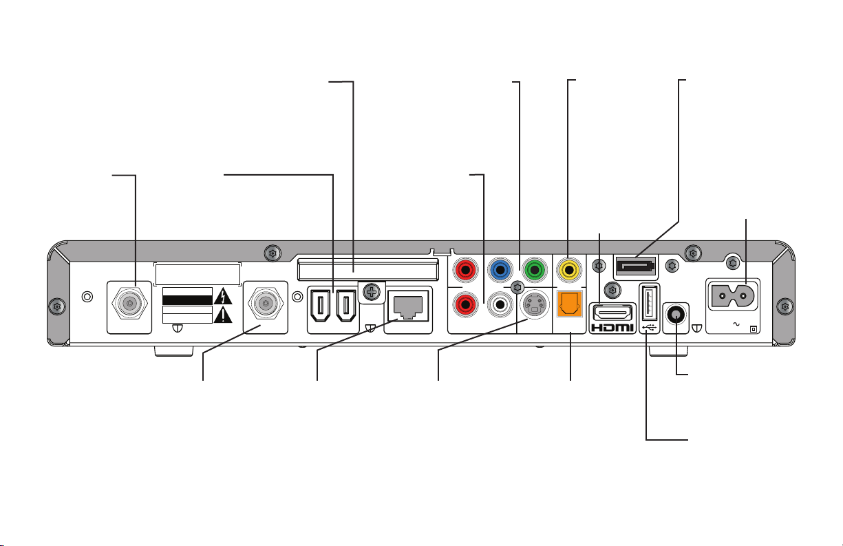
S-VIDEO
DIGITAL AUDIO
OUT OPTICAL
ETHERNET
VIDEO OUT
Pr Pb Y
COMPONENT VIDEO
1394CABLE IN TO TV
SATA
IR RECEIVE
POWER INPUT
120V AC 60Hz
DOUBLE INSULATED
AUDIO OUT
LR
CAUTION
RISK OF ELECTRIC SHOCK
DO NOT OPEN
CAUTION
WHEN SERVICING ONLY USE
IDENTICAL REPLACEMENT PARTS
IR RECEIVE
POWER INPUT
120V AC 60Hz
DOUBLE INSULATED
SAFETY INFORMATION (cont.)
Safety aspects of connections
Full details of the rear panel are on page 8.
Connecting
Do not connect your set-top (or any other equipment such as a TV or VCR)
to the power supply until you have properly connected all the other cables.
Your set-top operates with a 120 V AC, 60 Hz power supply.
Do not connect your set-top to any supply other than this.
This set-top is equipped with a two-wire power cord, with a polarized plug
at one end. The other end of the cord is fitted with a polarized connector,
which is shaped such that it can be fitted only one way into the power
input connector of your set-top. Connect this end first, before inserting the
polarized plug into the wall AC outlet.
Disconnecting
Disconnect your set-top from the power supply before you disconnect any
other equipment from its rear panel.
The only way to disconnect your set-top from the power supply is to remove
the power cord from the wall AC outlet. Therefore, you must install your set-
top near to the wall AC outlet, which should be easily accessible.
If you are in any doubt about the power cord, its plug, or its connection,
consult a qualified electrician.
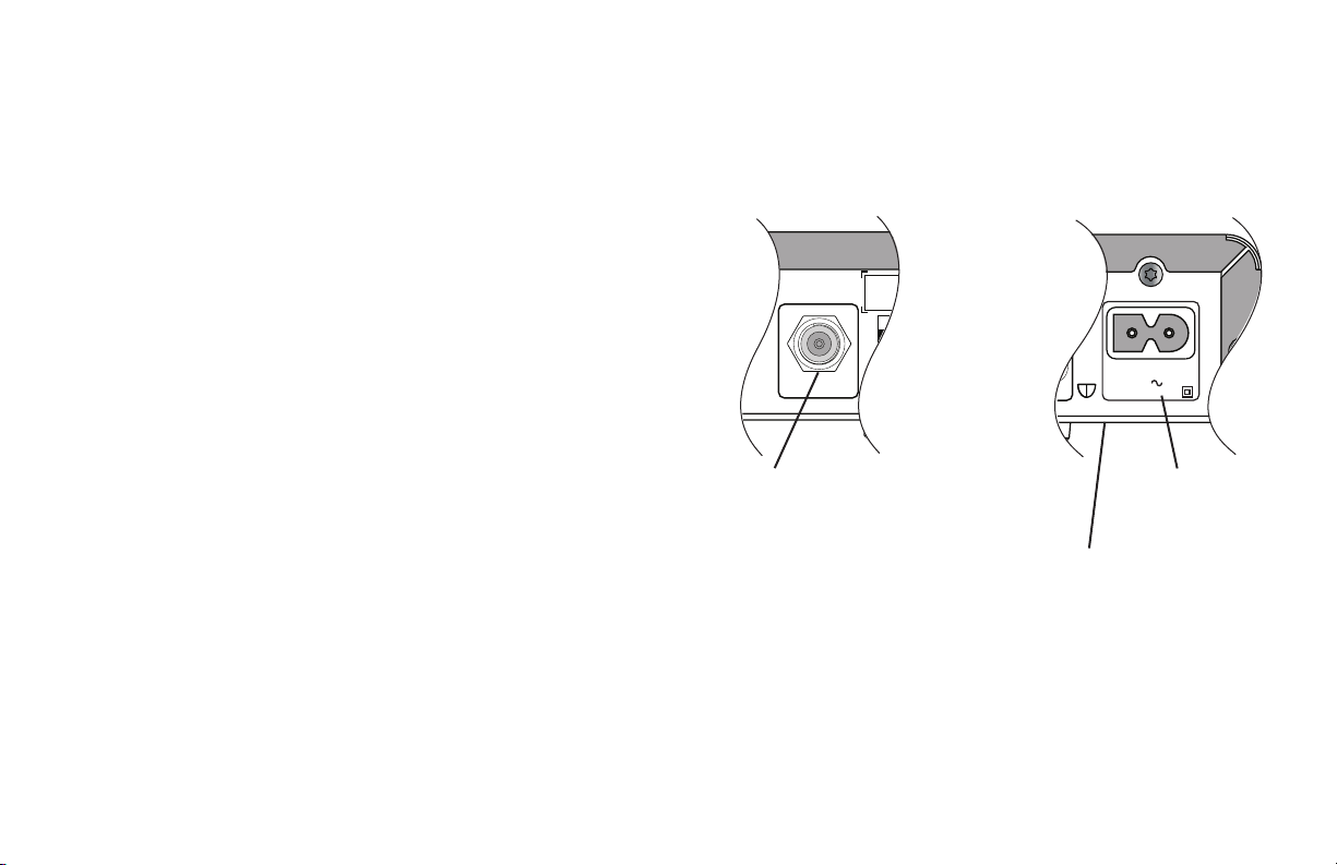
The CABLE IN connector is designed for
connection to a cable network only.
You must not connect any other equipment,
such as a VCR, to this input.
POWER INPUT
The model number, serial
number and electrical
rating of this set-top are
on a label on its base.

7
SAFETY INFORMATION (cont.)
Regulatory information
CAUTION: Do not attempt to modify your set-top without written
authorization from the manufacturer. Unauthorized modification
could void your authority to operate your set-top.
NOTE
Your set-top has been tested and found to comply with the limits for
a Class B digital device, pursuant to Part 15 of the FCC Rules. These
limits are designed to provide reasonable protection against harmful
interference in a residential installation. Your set-top generates, uses
and can radiate radio-frequency energy and, if not installed and used in
accordance with the instructions, may cause harmful interference to radio
communications.
However, there is no guarantee that interference will not occur in a
particular installation. If your set-top does cause harmful interference to
radio or television reception, which can be determined by turning your
set-top off and on, you are encouraged to try to correct the interference by
one or more of the following measures.
•Reorientorrelocatethereceivingantenna.
•Increasetheseparationbetweenyourset-topandthereceiver.
•Connectyourset-toptoanoutletonacircuitdifferentfromthatto
which the receiver is connected.
•Consultyourdealeroranexperiencedradio/TVtechnicianforhelp.
8
S-VIDEO
DIGITAL AUDIO
OUT OPTICAL
ETHERNET
VIDEO OUT
Pr Pb Y
COMPONENT VIDEO
1394CABLE IN TO TV
SATA
IR RECEIVE
POWER INPUT
120V AC 60Hz
DOUBLE INSULATED
AUDIO OUT
LR
CAUTION
RISK OF ELECTRIC SHOCK
DO NOT OPEN
CAUTION
WHEN SERVICING ONLY USE
IDENTICAL REPLACEMENT PARTS
REAR PANEL
AUDIO OUT
Audio outputs
(stereo, L and R)
CABLE IN
From cable
service-provider
TO TV
RF output to the
TV or VCR
S-VIDEO
S-video output
1394
For connections to
1394-compatible devices
COMPONENT VIDEO
Component video
output for analog
HDTV
POWER INPUT
(Make this
connection last
of all)
IR RECEIVE
Infra-red input from
a remote “eye”
DIGITAL AUDIO
OUT OPTICAL
Optical S/PDIF audio
output
ETHERNET
For future use
USB (Universal Serial
Bus) port
To connect a USB device
HDMI
TM
Video and audio
output for digital
HDTV
Separable security module
(behind cover)
Removal will interrupt your service
SATA
For connection to an
optional external hard
disk
VIDEO OUT
Composite
video output

9
REAR PANEL (cont.)
CABLE IN
Connect the cable service here.
TO TV
Connect to the RF/antenna input on your TV or
VCR (optional).
AUDIO OUT
Connect to the L and R audio inputs on your
stereo TV, stereo VCR, or optional stereo amplifier.
DIGITAL AUDIO
OUT OPTICAL
Connect to the optical digital audio input on
optional digital audio equipment, such as an audio
decoder or home theater receiver.
VIDEO OUT
Connect to the composite video input on your VCR
(or a standard TV).
S-VIDEO
Connect to the S-video input (if present) on your
VCR or TV.
COMPONENT
VIDEO
If your HDTV does not have an HDMI connector,
connect your HDTV here.
HDMI
(High Definition
Multimedia
Interface)
If your HDTV has an HDMI connector, connect
it here for a digital audio/video connection
(instead of using the AUDIO and three analog
COMPONENT VIDEO connectors).
IR RECEIVE
Connect to an optional remote “eye”.
SATA
Connect to an optional external hard disk
(if enabled by your cable service-provider).
1394
Connect to 1394-compatible devices.
USB
(Universal Serial
Bus) port
Connect to compatible optional equipment that
supports a USB 2.0 interface.
ETHERNET
For future use.
Separable security
module
(behind cover)
Removal will interrupt your service.
POWER INPUT
Connect your set-top’s power cord here.
Make this connection last of all.
10
CONNECTING THE EQUIPMENT
In order for you to view programs broadcast in high-definition, your set-top must be connected
to a suitable HDTV or computer monitor. Your set-top is also compatible with standard-definition
TVs and VCRs.
Your equipment should have been connected up by your installer. However, if you need to
disconnect and reconnect your equipment, read pages 10 through 14.
On pages 12 and 13, there are two typical connection setups for an HDTV, VCR, DVD player, and
home theater receiver.
These setups make efficient use of the connectors on your set-top. However, depending on
your other equipment and the connectors on it, the person who installed your system may have
chosen to connect things differently.
Both setups allow stereo recording and play-back of video tapes. You hear stereo sound from the
home theater’s loudspeakers.
Although the RF cables (shown by dashed lines in the diagrams) are not absolutely necessary,
we recommend that you connect them as a back-up. If you use the RF cables, you must tune
your TV (and VCR) to your set-top’s VHF output channel (3 or 4: consult your cable service-
provider to find which channel it is for your location).
Consult the manuals supplied with your TV and VCR for information on how to tune.
You can take advantage of the digital audio output from your set-top by connecting a suitable
cable between your home theater receiver and the DIGITAL AUDIO OUT OPTICAL connector (as
shown in the diagrams).
WARNINGS
Do not connect your set-top (or any other
equipment such as a TV or VCR) to the AC power
supply until you have properly connected all the
other cables.
Disconnect your set-top from the AC power supply
before you disconnect any other equipment from its
rear panel.
The only way to disconnect your set-top from the
AC power supply is to remove the AC power cord
(or switch the wall AC outlet switch, if present, to
its OFF position). Your set-top must therefore be
installed near the wall AC outlet, which should be
easily accessible.
The cable input is designed for connection to a
cable network only. You must not connect any other
equipment, such as a VCR, to this input.

11
CONNECTING THE EQUIPMENT (cont.)
Setup A - Home theater system with HDTV
(HDMI connection)
Setup A (see page 12) uses an HDMI connector to connect to the HDTV. This displays the highest quality picture
on the HDTV and also means there will be no picture degradation on any copy-protected programs (provided the
link remains secure – see right).
Variation
S-video provides a better TV picture than composite video, therefore, if your TV and VCR have S-video
connectors, replace the composite video connection with a S-video connection to your VCR, then connect directly
via a S-video connection from your VCR to your TV (or loop through your home theater receiver if you prefer).
Setup B - Home theater system with HDTV
(Component video / YPbPr connection)
Setup B (see page 13) uses a component video connection to connect to the HDTV. This displays a high definition
picture on your TV.
NOTE
Copy protection via an HDMI
secure link
The HDMI link between your set-
top and your HDTV should be a
secure link. When your set-top is
attached via an HDMI cable to an
HDCP-compliant (High-bandwidth
Digital Content Protection) HDTV,
the HDTV and set-top negotiate
a secure link, which allows your
set-top to transmit full resolution
video (picture) to your HDTV.
Not all HDTVs support HDCP. If
your set-top is connected to an
HDTV that does not support it, the
following may be displayed:
Your HDTV does not support HDCP.
Please use the YPbPr component
connection to watch TV.
The HDMI output is then disabled,
so no picture is transmitted from
this connector. In that case, use
the component video connectors
to connect up (see Setup B).
NOTE
How you set up your equipment may depend on your home theater receiver. For example, the optical audio
input may be associated with a particular video input. Consult your home theater user guide for further details.
 Loading...