


 Loading...
1•1
Chapter 1
Routine maintenance and servicing
Contents
Air cleaner filter element renewal . . . . . . . . . . . . . . . . . . . . . . . . . . . .24 Automatic transmission fluid level check . . . . . . . . . . . . . . . . . . . . . .13 Automatic transmission fluid renewal . . . . . . . . . . . . . . . . . . . . . . . . .33 Auxiliary drivebelt check and renewal . . . . . . . . . . . . . . . . . . . . . . . . .9 Battery check . . . . . . . . . . . . . . . . . . . . . . . . . . . . . . . . . . . . . . . . . . . .4 Brake fluid renewal . . . . . . . . . . . . . . . . . . . . . . . . . . . . . . . . . . . . . . .30 Brake pad, caliper and disc check . . . . . . . . . . . . . . . . . . . . . . . . . . .17 Carburettor fuel inlet filter cleaning . . . . . . . . . . . . . . . . . . . . . . . . . . .26 Clutch adjustment check . . . . . . . . . . . . . . . . . . . . . . . . . . . . . . . . . .28 Coolant renewal . . . . . . . . . . . . . . . . . . . . . . . . . . . . . . . . . . . . . . . . .32 Driveshaft CV joint and gaiter check . . . . . . . . . . . . . . . . . . . . . . . . .20 Electrical system check . . . . . . . . . . . . . . . . . . . . . . . . . . . . . . . . . . .14 Engine oil and filter renewal . . . . . . . . . . . . . . . . . . . . . . . . . . . . . . . . .6 Exhaust system check . . . . . . . . . . . . . . . . . . . . . . . . . . . . . . . . . . . .22 Fluid level checks . . . . . . . . . . . . . . . . . . . . . . . . . . . . . . . . . . . . . . . . .3 Fuel filter renewal - fuel injection models . . . . . . . . . . . . . . . . . . . . . .25 Fuel pump filter cleaning - carburettor models . . . . . . . . . . . . . . . . .12
Handbrake adjustment . . . . . . . . . . . . . . . . . . . . . . . . . . . . . . . . . . . |
.19 |
|
|
||
Headlamp aim check . . . . . . . . . . . . . . . . . . . . . . . . . . . . . . . . . . . . . |
31 |
1 |
Hinge and lock lubrication . . . . . . . . . . . . . . . . . . . . . . . . . . . . . . . . . |
21 |
|
Hose and fluid leak check |
8 |
|
|
||
Idle speed and mixture adjustments . . . . . . . . . . . . . . . . . . . . . . . . . |
11 |
|
Ignition system check . . . . . . . . . . . . . . . . . . . . . . . . . . . . . . . . . . . . . |
.9 |
|
Introduction . . . . . . . . . . . . . . . . . . . . . . . . . . . . . . . . . . . . . . . . . . . . |
.2 |
|
Manual transmission oil level check . . . . . . . . . . . . . . . . . . . . . . . . . . |
27 |
|
Rear brake shoe, wheel cylinder and drum check . . . . . . . . . . . . . . . |
29 |
|
Rear wheel bearing adjustment . . . . . . . . . . . . . . . . . . . . . . . . . . . . . |
18 |
|
Road test . . . . . . . . . . . . . . . . . . . . . . . . . . . . . . . . . . . . . . . . . . . . . . |
23 |
|
Roadwheel bolt tightness check . . . . . . . . . . . . . . . . . . . . . . . . . . . . |
16 |
|
Spark plug renewal . . . . . . . . . . . . . . . . . . . . . . . . . . . . . . . . . . . . . . . |
.7 |
|
Tyre checks . . . . . . . . . . . . . . . . . . . . . . . . . . . . . . . . . . . . . . . . . . . . |
.5 |
|
Vauxhall Astra/Belmont maintenance schedule . . . . . . . . . . . . . . . . . |
.1 |
|
Wiper blade check . . . . . . . . . . . . . . . . . . . . . . . . . . . . . . . . . . . . . . . |
15 |
|
Degrees of difficulty
Easy, suitable for |
Fairly easy, suitable |
Fairly difficult, suitable |
Difficult, suitable for |
Very difficult, |
novice with little |
for beginner with |
for competent DIY |
experienced DIY |
suitable for expert DIY |
experience |
some experience |
mechanic |
mechanic |
or professional |
1 Vauxhall Astra/Belmont maintenance schedule
The maintenance intervals in this manual are provided with the assumption that you, not the dealer, will be carrying out the work. These are the minimum maintenance intervals recommended by the manufacturer for vehicles driven daily. If you wish to keep your vehicle in peak condition at all times, you may wish to perform some of these procedures more often. We encourage frequent maintenance, because it enhances the efficiency, performance and resale value of your
vehicle. If the vehicle is driven in dusty areas, used to tow a trailer, or driven frequently at slow speeds (idling in traffic) or on short journeys, more frequent maintenance intervals are recommended.
When the vehicle is new, it should be serviced by a factoryauthorised dealer service department, in order to preserve the factory warranty.

1•2 Maintenance schedule
Every 250 miles (400 km) or weekly
m See Weekly checks
Every 9000 miles (15 000 km) or 6 months, whichever comes first
mRenew the engine oil and filter - early (pre-1987) models (Section 6)
Every 18 000 miles (30 000 km) or 12 months, whichever comes first
In addition to all the items listed previously, carry out the following:
mRenew the air cleaner filter element (Section 24)
mRenew the fuel filter (fuel injection models) (Section 25)
mClean the carburettor fuel inlet filter (Section 26)
mCheck the manual transmission oil level (Section 27)
mCheck the clutch adjustment (Section 28)
mCheck the condition of the rear brake shoes (renew if necessary), wheel cylinders and drums (Section 29)
mRenew the brake fluid (Section 30)
mCheck the headlamp alignment (Section 31)
Every 9000 miles (15 000 km) or 12 months, whichever comes first
mRenew the engine oil and filter - later (1987-on) models (Section 6)
mRenew the spark plugs (Section 7)
mCheck and adjust the valve clearances - 1.2 litre models (Chapter 2A)
mCheck all underbonnet and underbody components, pipes and hoses for leaks (Section 8)
mCheck the condition of the auxiliary drivebelt, and renew if necessary (Section 9)
mCheck the ignition system components and renew the contact breaker points (Section 10)
mCheck idle speed and mixture adjustments (Section 11)
mClean the fuel pump filter (carburettor models) (Section 12)
mCheck the throttle cable adjustment (Chapter 4A or 4B)
mCheck the automatic transmission fluid level (Section 13)
mCheck the operation of the horn, all lights, and the wipers and washers (Section 14)
mCheck the condition of the wiper blades (Section 15)
mCheck the tightness of the roadwheel bolts (Section 16)
mCheck the condition of the front, and rear (where fitted) brake pads (renew if necessary), and the calipers and discs (Section 17)
mCheck the rear wheel bearings adjustment (Section 18)
mCheck the handbrake adjustment (Section 19)
mCheck the driveshaft CV joints and gaiters for condition (Section 20)
mLubricate locks and hinges (Section 21)
mCheck the exhaust system for condition and security (Section 22)
mRoad test the vehicle (Section 23)
Every 2 years (regardless of mileage)
In addition to all the relevant items listed previously, carry out the following:
m Renew the coolant (Section 32)
Every 36 000 miles (60 000 km) or 4 years, whichever comes first
In addition to all the relevant items listed previously, carry out the following:
mRenew the automatic transmission fluid (Section 33)
mRenew the camshaft toothed belt -
1.3, 1.4, 1.6, 1.8 and 2.0 litre 8-valve engines (Chapter 2B), 2.0 litre 16-valve engines (Chapter 2C)
Every 54 000 miles (90 000 km) or 3 years, whichever comes first
In addition to all the relevant items listed previously, carry out the following:
m Renew the braking system seals and hose (Chapter 9)
Maintenance - component location 1•3
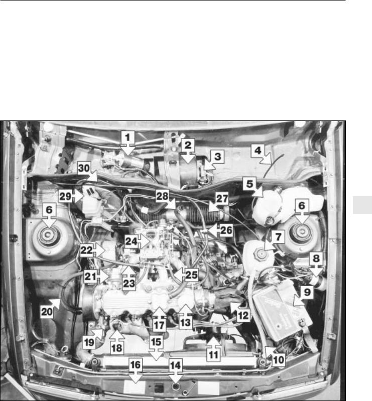
Underbonnet view of an early 1.6 litre model (air cleaner removed for clarity)
1 |
Wiper motor |
11 |
Radiator cooling fan |
21 |
Fuel pump |
2 |
Heater blower motor |
12 |
Distributor cover |
22 |
Alternator |
3 |
Heater blower motor resistor |
13 |
Engine oil filler |
23 |
Accelerator cable |
4 |
Windscreen washer tube |
14 |
Bonnet catch |
24 |
Carburettor |
5 |
Screen washer reservoir |
15 |
Radiator |
25 |
Choke cable |
6 |
Suspension turrets |
16 |
VIN plate |
26 |
Servo non-return valve |
7 |
Coolant expansion tank |
17 |
Engine breather |
27 |
Steering rack bellows |
8 |
Ignition coil |
18 |
Air cleaner hot air pick-up |
28 |
Air cleaner breather hose |
9 |
Battery |
19 |
Thermostat housing |
29 |
Brake fluid reservoir |
10 Coolant hose |
20 |
Fuel hoses |
30 |
Brake servo |
|
1

1•4 Maintenance - component location
|
|
Underbonnet view of an early 1.8 litre model |
|
|
|
1 |
Screen washer reservoir |
11 |
Radiator fan |
21 |
Breather hose |
2 |
Headlamp washer filler cap |
12 |
Distributor |
22 |
Throttle valve housing |
3 |
Headlamp washer relay and fuse |
13 |
Engine oil filler |
23 |
Fuel rail |
4 |
Suspension turrets |
14 |
Bonnet catch |
24 |
Fuel pressure regulator |
5 |
Coolant expansion tank filler |
15 |
Radiator |
25 |
Servo non return valve |
6 |
Control relay (fuel injection system) |
16 |
VIN plate |
26 |
Steering rack bellows |
7 |
Ignition coil |
17 |
Engine breather |
27 |
Accelerator cable |
8 |
Horn |
18 |
Thermostat housing |
28 |
Brake fluid reservoir |
9 |
Battery |
19 |
Air cleaner |
29 |
Brake servo |
10 |
Coolant hose |
20 |
Airflow meter |
|
|
|
|
|
|
|
|
|
|
|
|
|
|
Maintenance - component location 1•5
|
|
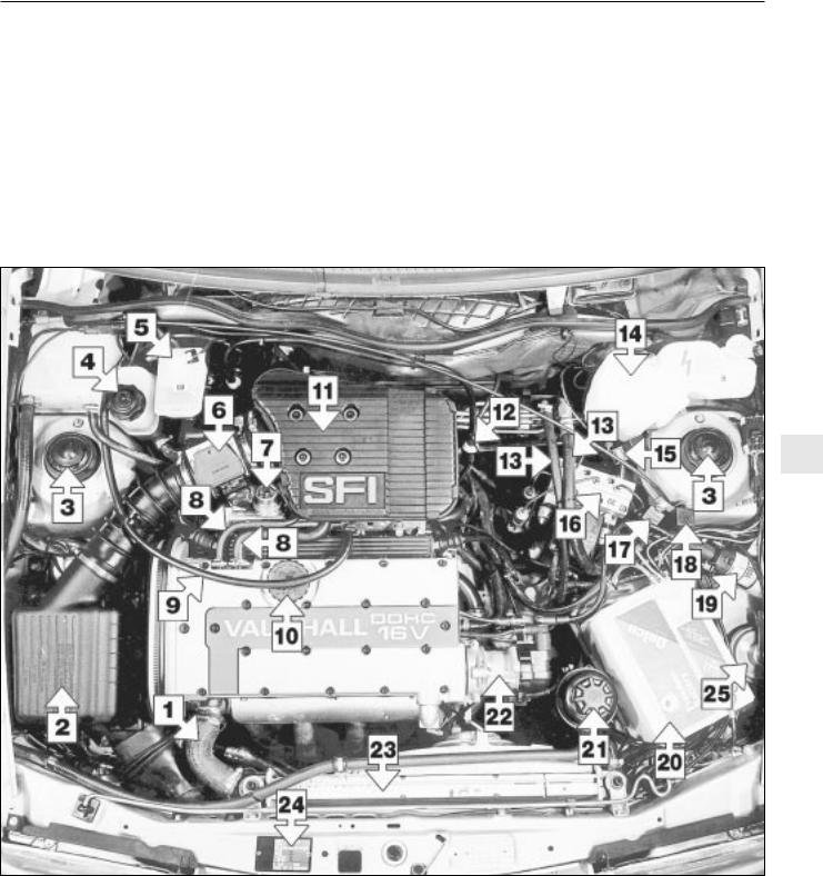
Underbonnet view of a 2.0 litre 16-valve model |
|
|
|
1 |
Radiator top hose |
10 |
Engine oil filler cap |
18 |
Fuel injection control relay |
2 |
Air cleaner |
11 |
Pre-volume chamber |
19 |
Ignition coil |
3 |
Suspension turrets |
12 |
Brake servo non-return valve |
20 |
Battery |
4 |
Coolant filler cap |
13 |
Power steering hoses |
21 |
Power steering fluid reservoir |
5 |
Brake fluid reservoir |
14 |
Windscreen washer reservoir |
22 |
Distributor |
6 |
Air mass meter |
15 |
Headlamp washer relay |
23 |
Radiator |
7 |
Fuel pressure regulator |
16 |
ABS hydraulic unit |
24 |
Vehicle identification plate |
8 |
Breather hoses |
17 |
ABS surge arrester relay |
25 |
Horn |
9 |
Throttle cable |
|
|
|
|
1
1•6 Maintenance - component location
|
|
|
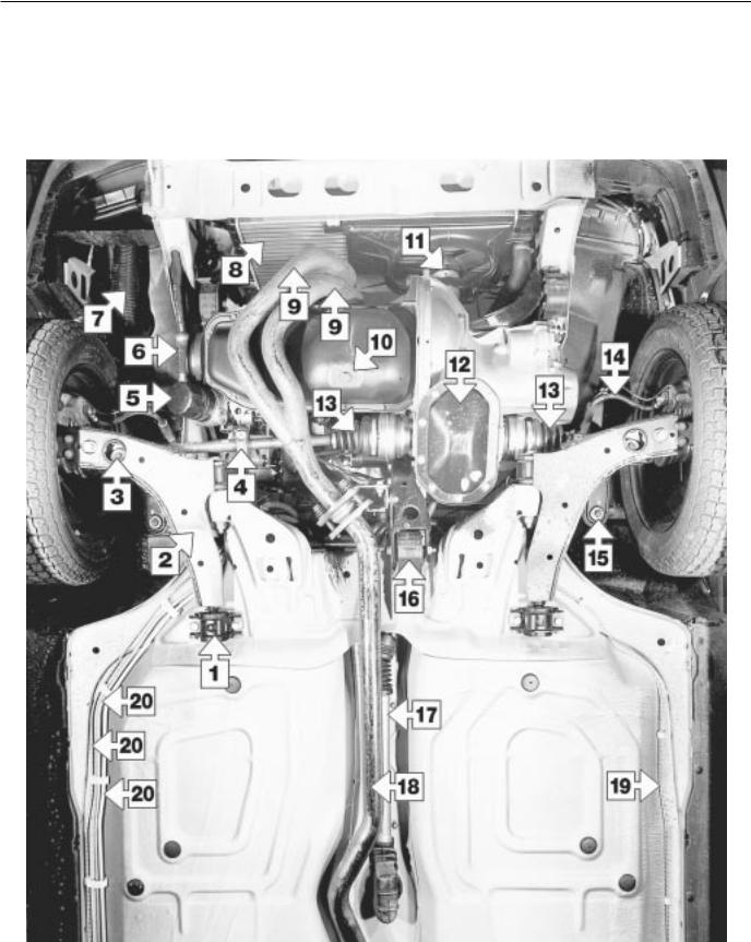
Front underbody view of a 1.8 litre model - other models similar |
|
|||
|
1 |
Control arm rear bush |
8 |
Radiator |
15 |
Steering balljoint attachment |
|
|
2 |
Control arm |
9 |
Exhaust downpipes |
16 |
Engine/transmission rear mounting |
|
|
3 |
Anti-roll bar link |
10 |
Sump drain plug |
17 |
Gearchange tube |
|
|
4 |
Driveshaft damper weight |
11 |
Radiator fan |
18 |
Exhaust pipe |
|
|
5 |
Engine oil filter |
12 |
Gearbox sump |
19 |
Brake pipe |
|
|
6 |
Oil cooler hose |
13 |
Driveshaft bellows |
20 |
Brake and fuel pipes |
|
|
7 |
Air induction trunking |
14 |
Brake hose |
|
|
|
|
|
|
|
|
|
|
|
|
|
|
|
|
|
|
|
Maintenance - introduction 1•7
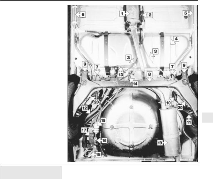
Rear underbody view of a 1.8 litre model - other models similar
1Centre silencer
2Handbrake adjuster
3Handbrake cables
4Fuel tank
5Brake pipe
6Brake and fuel pipes
7Brake hoses
8Axle beam
9Axle mountings
10Spring
11Shock absorber mounting
12Fuel filler pipe
13Fuel gauge sender/fuel tank outlet
14Fuel tank breather
15Fuel filter*
16Fuel pressure regulator*
17Fuel pump*
18Towing eye
19Rear silencer
20Rear brake pipes
*Fuel injection models only
1
2 Introduction
General information
This Chapter is designed to help the home mechanic maintain his/her vehicle for safety, economy, long life and peak performance.
The Chapter contains a master maintenance schedule, followed by sections dealing specifically with each task on the schedule. Visual checks, adjustments, component renewal and other helpful items are included. Refer to the accompanying illustrations of the engine compartment and the underside of the vehicle for the locations of the various components.
Servicing of your vehicle in accordance with the mileage/time maintenance schedule and the following sections will provide a planned maintenance programme, which should result in a long and reliable service life. This is a comprehensive plan, so maintaining some
items but not others at the specified service intervals, will not produce the same results.
As you service your vehicle, you will discover that many of the procedures can - and should - be grouped together, because of the particular procedure being performed, or because of the close proximity of two otherwise-unrelated components to one another. For example, if the vehicle is raised for any reason, the exhaust can be inspected at the same time as the suspension and steering components.
The first step in this maintenance programme is to prepare yourself before the actual work begins. Read through all the sections relevant to the work to be carried out, then make a list and gather together all the parts and tools required. If a problem is encountered, seek advice from a parts specialist, or a dealer service department.
Intensive maintenance
If, from the time the vehicle is new, the routine maintenance schedule is followed closely, and frequent checks are made of fluid
levels and high-wear items, as suggested throughout this manual, the engine will be kept in relatively good running condition, and the need for additional work will be minimised.
It is possible that there will be times when the engine is running poorly due to the lack of regular maintenance. This is even more likely if a used vehicle, which has not received regular and frequent maintenance checks, is purchased. In such cases, additional work may need to be carried out, outside of the regular maintenance intervals.
If engine wear is suspected, a compression test (Chapter 2) will provide valuable information regarding the overall performance of the main internal components. Such a test can be used as a basis to decide on the extent of the work to be carried out. If for example a compression test indicates serious internal engine wear, conventional maintenance as described in this Chapter will not greatly improve the performance of the engine, and may prove a waste of time and money, unless extensive overhaul work (Chapter 2) is carried out first.
1•8 Maintenance procedures
The following series of operations are those most often required to improve the performance of a generally poor-running engine:
Primary operations
a)Clean, inspect and test the battery (Section 4).
b)Check all the engine-related fluids (Section 3).
c)Check the condition and tension of the auxiliary drivebelt (Section 9).
d)Renew the spark plugs (Section 7).
e)Inspect the ignition system components (Section 10).
f)| Inspect the ignition HT leads (Section 10).
g)Check the condition of the air filter, and renew if necessary (Section 24).
h)Check the condition of all hoses, and
check for fluid leaks (Section 8).
If the above operations do not prove fully effective, carry out the following secondary operations:
Secondary operations
All items listed under “Primary operations”,
plus the following:
a)Check the charging system (Chapter 5A).
b)Check the fuel system (Chapter 4A or 4B).
c)Renew the air filter (Section 24).
d)Renew the distributor cap and rotor arm (Section 10).
e)Renew the ignition HT leads (Section 10).
Every 250 miles or weekly
3 Fluid level checks |
4 Battery check |
5 Tyre checks |
See “Weekly checks” |
See “Weekly checks” |
See “Weekly checks” |
Every 9000 miles
6 Engine oil and filter renewal
1Frequent oil and filter changes are the most important preventative maintenance procedures which can be undertaken by the DIY owner. As engine oil ages, it becomes diluted and contaminated, which leads to premature engine wear.
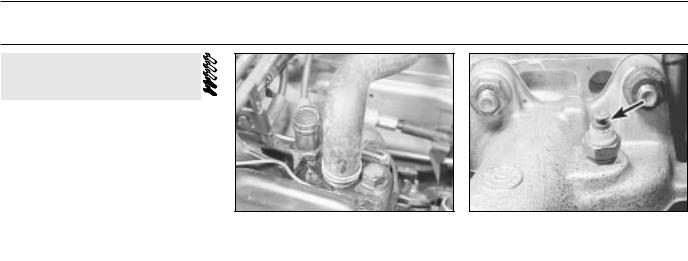
2Before starting this procedure, gather together all the necessary tools and materials. Also make sure that you have plenty of clean rags and newspapers handy, to mop up any spills. Ideally, the engine oil should be warm, as it will drain more easily, and more built-up sludge will be removed with it. Take care not to touch the exhaust or any other hot parts of the engine when working under the vehicle. To avoid any possibility of scalding, and to protect yourself from possible skin irritants and other harmful contaminants in used engine oils, it is advisable to wear gloves when carrying out this work. Access to the underside of the vehicle will be greatly improved if it can be raised on a lift, driven
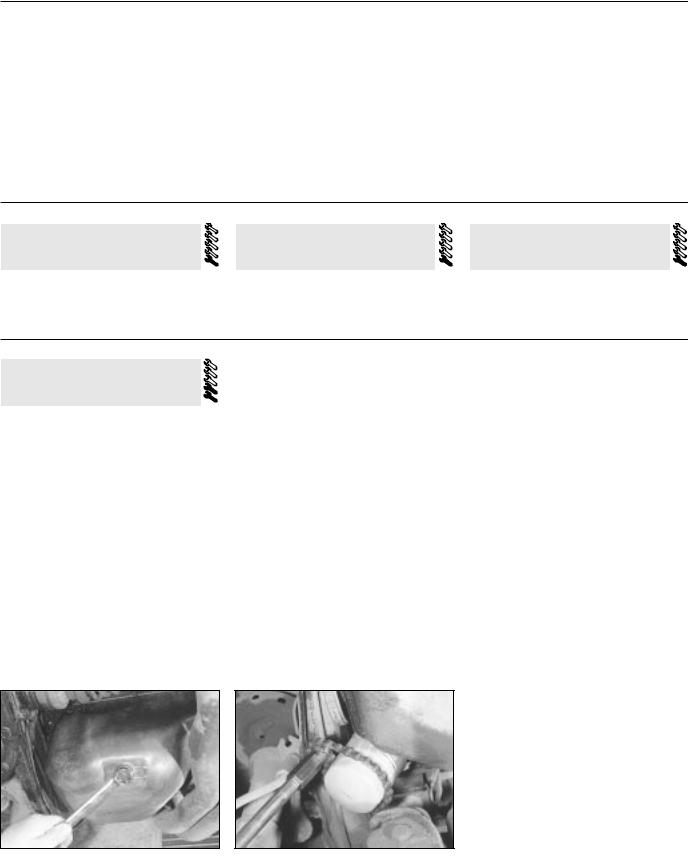
6.4 Removing the sump drain plug
onto ramps, or jacked up and supported on axle stands (see “Jacking and Vehicle Support”). Whichever method is chosen, make sure that the vehicle remains level, or if it is at an angle, that the drain plug is at the lowest point. The drain plug is located at the rear of the sump.
3Remove the oil filler cap from the camshaft cover (twist it through a quarter-turn anticlockwise and withdraw it).
4Using a spanner, or preferably a socket and bar, slacken the drain plug about half a turn (see illustration). Position the draining container under the drain plug, then remove the plug completely. If possible, try to keep the plug pressed into the sump while unscrewing it by hand the last couple of turns. As the plug releases from the threads, move it away sharply, so that the stream of oil from the sump runs into the container, not up your sleeve!
5Allow some time for the oil to drain, noting that it may be necessary to reposition the container as the oil flow slows to a trickle.
6After all the oil has drained, wipe the drain plug and the sealing washer with a clean rag. Examine the condition of the sealing washer,
6.9 Using an oil filter removal tool to unscrew the oil filter
and renew it if it shows signs of scoring or other damage which may prevent an oil-tight seal. Clean the area around the drain plug opening, and refit the plug complete with the washer. Tighten the plug securely, preferably to the specified torque, using a torque wrench.
7The oil filter is located at the right-hand end of the engine.
8Move the container into position under the oil filter.
9Use an oil filter removal tool to slacken the filter initially, then unscrew it by hand the rest of the way (see illustration). Empty the oil from the old filter into the container.
10Use a clean rag to remove all oil, dirt and sludge from the filter sealing area on the engine. Check the old filter to make sure that the rubber sealing ring has not stuck to the engine. If it has, carefully remove it.
11Apply a light coating of clean engine oil to the sealing ring on the new filter, then screw the filter into position on the engine. Tighten the filter firmly by hand only - do not use any tools.
12Remove the old oil and all tools from under the vehicle then, if applicable, lower the vehicle to the ground.
13Fill the engine through the filler hole in the camshaft cover, using the correct grade and type of oil (refer to Section 3 for details of topping-up). Pour in half the specified quantity of oil first, then wait a few minutes for the oil to drain into the sump. Continue to add oil, a small quantity at a time, until the level is up to the lower mark on the dipstick. Adding a further 1.0 litre (approx.) will bring the level up to the upper mark on the dipstick.
14Start the engine and run it for a few minutes, while checking for leaks around the oil filter seal and the sump drain plug. Note that there may be a delay of a few seconds before the low oil pressure warning light goes out when
Every 9000 miles 1•9
the engine is first started, as the oil circulates through the new oil filter and the engine oil galleries before the pressure builds up.
15Stop the engine, and wait a few minutes for the oil to settle in the sump once more. With the new oil circulated and the filter now completely full, recheck the level on the dipstick, and add more oil as necessary.
16Dispose of the used engine oil safely, with reference to “General repair procedures”.
Note: It is antisocial and illegal to dump oil down the drain. To find the location of your local oil recycling bank, call this number free.
7 Spark plug renewal
1The correct functioning of the spark plugs is vital for the correct running and efficiency of the engine. It is essential that the plugs fitted are appropriate for the engine, the suitable type being specified at the end of this Chapter. If the correct type of plug is used and the engine is in good condition, the spark plugs should not need attention between scheduled renewal intervals, except for adjustment of their gaps. Spark plug cleaning is rarely necessary, and should not be attempted unless specialised equipment is available, as damage can easily be caused to the firing ends.
2To remove the plugs, first open the bonnet. On 1.2 litre models remove the air cleaner as described in Chapter 4A. On 2.0 litre 16-valve engines undo the retaining screws and remove the spark plug lead cover from the engine.
3Mark the HT leads 1 to 4, to correspond to the cylinder the lead serves (No 1 cylinder is nearest the timing belt end of the engine). Pull the HT leads from the plugs by gripping the end connectors, not the leads, otherwise the lead connections may be fractured.
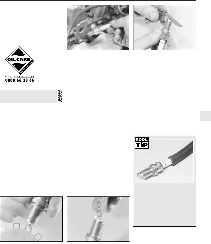
7.10b Measuring a spark plug electrode gap using a wire gauge
7.5 Removing a spark plug - 1.6 litre engine shown
4It is advisable to remove any dirt from the spark plug recesses using a clean brush, vacuum cleaner or compressed air, before removing the plugs, to prevent the dirt dropping into the cylinders.
5Unscrew the plugs using a spark plug spanner, a suitable box spanner, or a deep socket and extension bar (see illustration). Keep the socket in alignment with the spark plugs, otherwise if it is forcibly moved to either side, the porcelain top of the spark plug may be broken off. As each plug is removed, examine it as follows.
6Examination of the spark plugs will give a good indication of the condition of the engine. If the insulator nose of the spark plug is clean and white, with no deposits, this is indicative of a weak mixture or too hot a plug (a hot plug transfers heat away from the electrode slowly, while a cold plug transfers heat away quickly).
7If the tip and insulator nose are covered with hard black-looking deposits, then this is indicative that the idle mixture is too rich. Should the plug be black and oily, then it is likely that the engine is fairly worn, as well as the mixture being too rich.
8If the insulator nose is covered with lighttan to greyish-brown deposits, then the mixture is correct and it is likely that the engine is in good condition.
9The spark plug gap is of considerable importance as, if it is too large or too small, the size of the spark and its efficiency will be seriously impaired. For the best results, the spark plug gap should be set in accordance with the Specifications at the end of this Chapter.
7.11 Adjusting a spark plug electrode gap using a special tool
7.10a Measuring a spark plug electrode gap using a feeler blade
10To set the spark plug gap, measure the gap between the electrodes with a feeler blade, and then bend open, or close, the outer plug electrode until the correct gap is achieved (see illustrations). The centre electrode should never be bent, as this may crack the insulation and cause plug failure, if nothing worse.
11Special spark plug electrode gap adjusting tools are available from most motor accessory shops (see illustration).
12Before fitting the new spark plugs, check that the threaded connector sleeves on the top of the plug are tight, and that the plug exterior surfaces and threads are clean.
13 Screw in the spark plugs by hand where |
1 |
possible, then tighten them to the specified torque. Take extra care to enter the plug threads correctly, as the cylinder head is of light alloy construction.
It is very often difficult to insert spark plugs into their holes without crossthreading them. To avoid this, fit a short length of 5/16-inch internal diameter hose over the end of the spark plug. The flexible hose acts as a universal joint to help align the plug with the plug hole. Should the plug begin to cross-thread, the hose will slip on the spark plug, preventing thread damage to the aluminium cylinder head.
14 Reconnect the HT leads in their correct order. On 1.2 litre models refit the air cleaner (Chapter 4A) and on 2.0 litre 16-valve models, refit the spark plug lead cover.
1•10 Every 9000 miles
8 Hose and fluid leak check
1 Visually inspect the engine joint faces, gaskets and seals for any signs of water or oil leaks. Pay particular attention to the areas around the camshaft cover, cylinder head, oil filter and sump joint faces. Bear in mind that, over a period of time, some very slight seepage from these areas is to be expected; what you are really looking for is any indication of a serious leak. Should a leak be found, renew the offending gasket or oil seal by referring to the appropriate Chapters in this manual.
2Also check the security and condition of all the engine-related pipes and hoses. Ensure that all cable-ties or securing clips are in place, and in good condition. Clips which are broken or missing can lead to chafing of the hoses pipes or wiring, which could cause more serious problems in the future.
3Carefully check the radiator hoses and heater hoses along their entire length. Renew any hose which is cracked, swollen or deteriorated. Cracks will show up better if the hose is squeezed. Pay close attention to the hose clips that secure the hoses to the cooling system components. Hose clips can pinch and puncture hoses, resulting in cooling system leaks. If wire-type hose clips are used, it may be a good idea to replace them with screw-type clips.
4Inspect all the cooling system components (hoses, joint faces etc.) for leaks. Where any problems of this nature are found on system components, renew the component or gasket with reference to Chapter 3.
A leak in the cooling system will usually show up as whiteor rust-coloured deposits on the area adjoining the leak.
5 Where applicable, inspect the automatic transmission fluid cooler hoses for leaks or deterioration.
6 With the vehicle raised, inspect the petrol tank and filler neck for punctures, cracks and other damage. The connection between the filler neck and tank is especially critical. Sometimes, a rubber filler neck or connecting hose will leak due to loose retaining clamps or deteriorated rubber.
7Carefully check all rubber hoses and metal fuel lines leading away from the petrol tank. Check for loose connections, deteriorated hoses, crimped lines and other damage. Pay particular attention to the vent pipes and hoses, which often loop up around the filler neck and can become blocked or crimped. Follow the lines to the front of the vehicle, carefully inspecting them all the way. Renew damaged sections as necessary.
8From within the engine compartment, check the security of all fuel hose attachments and pipe unions, and inspect the fuel hoses and vacuum hoses for kinks, chafing and deterioration.
9Where applicable, check the condition of the power steering fluid hoses and pipes.
9 Auxiliary drivebelt check and renewal
Alternator drivebelt
Checking and adjustment
1Correct tensioning of the auxiliary drivebelt will ensure that it has a long life. Beware, however, of overtightening, as this can cause excessive wear in the alternator.
2The belt should be inspected along its entire length, and if it is found to be worn, frayed or cracked, it should be renewed as a precaution against breakage in service. It is advisable to carry a spare drivebelt of the correct type in the vehicle at all times.
3Although special tools are available for measuring the belt tension, a good approximation can be achieved if the belt is tensioned so that there is approximately 13 mm of free movement under firm thumb pressure at the mid-point of the longest run between pulleys. If in doubt, err on the slack side, as an excessively-tight belt may cause damage to the alternator or other components.
4If adjustment is required, loosen the alternator upper mounting nut and bolt - use two spanners, one to counterhold the bolt. Lever the alternator away from the engine using a wooden lever at the mounting bracket until the correct tension is achieved, then tighten the bolt securing the adjuster bracket, and the alternator mounting nuts and bolts. On no account lever at the free end of the alternator, as serious internal damage could be caused to the alternator.
Removal, renewal and refitting
5 To remove the belt, simply loosen the mounting nuts and bolts, and the bolt securing the adjuster bracket, as described previously, and slacken the belt sufficiently to slip it from the pulleys. On models with power steering it will first be necessary to remove the power steering pump drivebelt as described below.
6 Refit the belt, and tension it as described previously. Note that when a new belt has been fitted it will probably stretch slightly to
start with and the tension should be rechecked, and if necessary adjusted, after about 5 minutes running.
Power steering pump drivebelt
Checking and adjustment
7Refer to the information given in paragraphs 1 to 3, noting that there should be approximately 8 mm of free movement in the belt.
8If adjustment is required, slacken the adjuster bolt locknut (situated on the base of the pump) and rotate the adjuster nut as necessary to tension the belt. Once the belt tension is correct, securely tighten the locknut.
Removal, renewal and refitting
9 To remove the belt, simply loosen the locknut and fully slacken the adjuster nut sufficiently to slip the drivebelt from the pulleys.
10 Refit the belt, and tension it as described previously. Note that when a new belt has been fitted it will probably stretch slightly to start with and the tension should be rechecked, and if necessary adjusted, after about 5 minutes running.
Alternator/power steering pump drivebelt - later 1.6 litre models
Checking and adjustment
11 From March 1987 onwards, a single drivebelt is used for the alternator and power steering pump on 1.6 litre engines. The drivebelt is of the ribbed type and runs at a higher tension than the previous (V) belt.
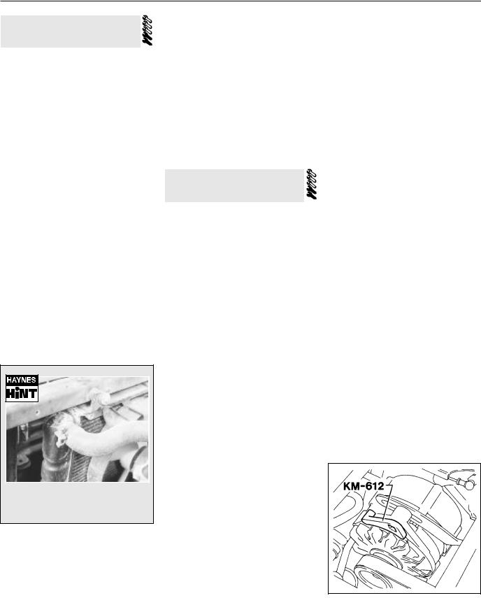
12To set the tension accurately, make up or obtain an adapter as shown (see illustration).
13Slacken the alternator pivot and adjusting strap bolts and fit the adapter. Using a torque wrench apply a load of 55 Nm (40 lbf ft) for a new belt, or 50 Nm (37 lbf ft) for an old belt. Keep the tension applied and securely tighten the alternator bolts.
Removal, renewal and refitting
14 To remove the belt, simply loosen the alternator pivot and strap bolts and slip the drivebelt from the pulleys.
9.12 Adapter KM-612 used for setting drivebelt tension on later 1.6 litre models
Every 9000 miles 1•11
15 Refit the belt, and tension it as described previously. Note that when a new belt has been fitted it will probably stretch slightly to start with and the tension should be rechecked, and if necessary adjusted, after about 5 minutes running.
10 Ignition system check
Models with contact breaker ignition system
1 Renew the contact breaker points and adjust the gap and dwell angle as described in Chapter 5B. After adjustment put one or two drops of engine oil into the centre of the cam recess where appropriate and smear the surfaces of the cam itself with petroleum jelly. Do not over-lubricate as any excess could get onto the contact point surfaces and cause ignition difficulties.
2The spark plug (HT) leads should also be checked.
3Ensure that the leads are numbered before removing them, if not make identification marks to avoid confusion when refitting. Pull the leads from the plugs by gripping the end fitting, not the lead, otherwise the lead connection may be fractured.
4Check inside the end fitting for signs of corrosion, which will look like a white crusty powder. Push the end fitting back onto the spark plug ensuring that it is a tight fit on the plug. If not, remove the lead again and use pliers to carefully crimp the metal connector inside the end fitting until it fits securely on the end of the spark plug.
5Using a clean rag, wipe the entire length of the lead to remove any built-up dirt and grease. Once the lead is clean, check for burns, cracks and other damage. Do not bend the lead excessively or pull the lead lengthwise - the conductor inside might break.
6Disconnect the other end of the lead from the distributor cap. Again, pull only on the end fitting. Check for corrosion and a tight fit in the same manner as the spark plug end. If an ohmmeter is available, check the resistance of the lead by connecting the meter between the spark plug end of the lead and the segment inside the distributor cap. Refit the lead securely on completion.
7Check the remaining leads one at a time, in the same way.
8If new spark plug (HT) leads are required, purchase a set for your specific car and engine.
9Remove the distributor cap, wipe it clean and carefully inspect it inside and out for signs of cracks, carbon tracks (tracking) and worn, burned or loose contacts; check that the cap’s carbon brush is unworn, free to move against spring pressure and making good contact with the rotor arm. Also inspect the cap seal for signs of wear or damage and
10.9a Remove the distributor cap . . .
renew if necessary. Remove and inspect the rotor arm (see illustrations). It is common practice to renew the cap and rotor arm whenever new spark plug (HT) leads are fitted. When fitting a new cap, remove the leads from the old cap one at a time and fit them to the new cap in the exact same location - do not simultaneously remove all the leads from the old cap or firing order confusion may occur. On refitting ensure that the arm is securely pressed onto the shaft and the cap is securely fitted.
10 Even with the ignition system in first class condition, some engines may still occasionally experience poor starting attributable to damp ignition components. To disperse moisture a moister dispersant aerosal can be very effective.
Models with an electronic ignition system
Warning: Voltages produced by an electronic ignition system are considerably higher than those produced by conventional
ignition systems. Extreme care must be taken when working on the system with the ignition switched on. Persons with surgically-implanted cardiac pacemaker devices should keep well clear of the ignition circuits, components and test equipment.
11Check the condition of the HT leads and distributor components as described above in paragraphs 3 to 10.
12Check the ignition timing (Chapter 5C).
11 Idle speed and mixture adjustments
1 Before checking the idle speed and mixture setting, always check first the following.
a)Check that the ignition timing is accurate (Chapter 5B or 5C).
b)Check that the spark plugs are in good condition and correctly gapped (Section 25).
c)Check that the accelerator cable and, on carburettor models, the choke cable
10.9b . . . and pull off the rotor arm from the distributor shaft (1.6 litre model shown)
(where fitted) is correctly adjusted (see relevant Part of Chapter 4).
d)Check that the crankcase breather hoses are secure with no leaks or kinks (Chapter 2).
e)Check that the air cleaner filter element is clean (Section 31).
f)Check that the exhaust system is in good condition (see relevant Part of Chapter 4).
g)If the engine is running very roughly, check the compression pressures as
described in Chapter 2.
2 Take the car on a journey of sufficient length to warm it up to normal operating temperature. Proceed as described under the 1 relevant sub-heading.
Note: Adjustment should be completed within two minutes of return, without stopping the engine. If this cannot be achieved, or if the radiator electric cooling fan operates, wait for the cooling fan to stop and clear any excess fuel from the inlet manifold by racing the engine two or three times to between 2000 and 3000 rpm, then allow it to idle again.
Carburettor models
3Connect a tachometer in accordance with the manufacturer’s instructions.
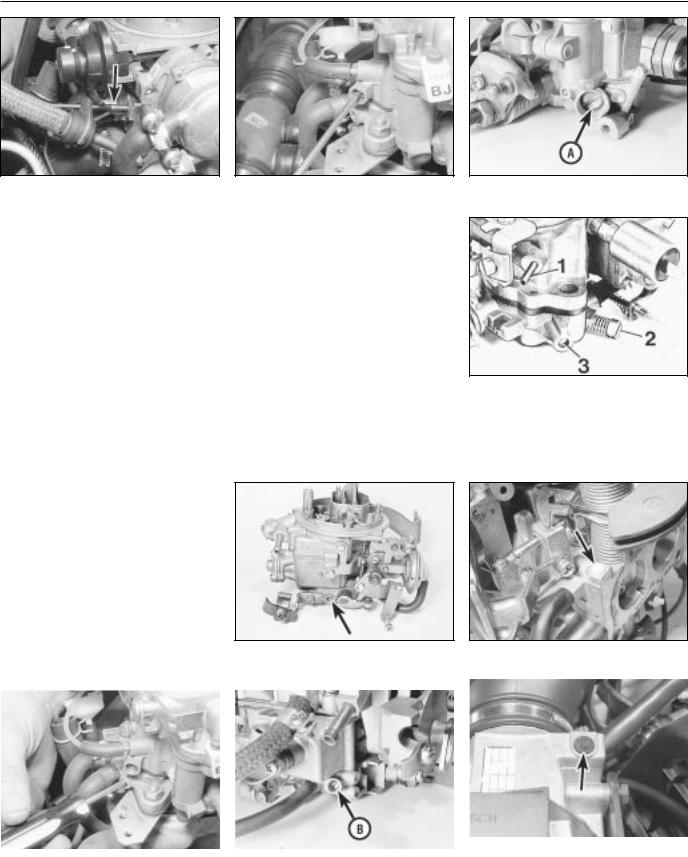
4If the idle speed is outside the specified tolerance (see Specifications), turn the adjustment screw as necessary (see illustrations). This will not alter the CO content of the exhaust gas to any extent.
5If an exhaust gas analyser is available, check the exhaust gas CO content as follows.
11.4a Idle speed adjustment screw (arrowed) - 32TL carburettor
1•12 Every 9000 miles
11.4b Idle speed adjustment screw (arrowed) - 2E3 carburettor
6Remove the tamperproof cap (where fitted) from the mixture adjustment screw. Satisfy yourself that you are not breaking any local or national laws by so doing.
7With the engine at normal operating temperature, check the CO content of the exhaust gas. If it is outside the permitted tolerance, turn the mixture adjusting screw as necessary to correct it (see illustrations).
8When the adjustments are correct, fit a new tamperproof cap to the screw and disconnect the tachometer. Note: On 32TL and Varajet II carburettors, if it proves difficult to adjust the idle speed and/or mixture setting then it is likely that the base idle speed is incorrect. Setting of this requires the use of an accurate vacuum gauge and should therefore be entrusted to a Vauxhall/Opel dealer.
Fuel-injected models
1.8 litre models
9 With the engine at normal operating temperature, connect a tachometer in accordance with its manufacturer’s instructions.
10Allow the engine to idle, and compare the idle speed with that given in the Specifications. If adjustment is necessary, slacken the locknut and turn the idle speed adjusting screw until the specified speed is obtained. The adjusting screw is situated on the throttle valve housing. Tighten the locknut on completion.
11If an exhaust gas analyser is available, check the mixture (CO level) as follows.
12With the engine idling at the specified speed, read the CO level and compare it with that specified.
11.4c Adjusting the idle speed - Varajet carburettor
13If adjustment is necessary, remove the tamperproof cap from the mixture adjusting screw on the airflow sensor (see illustration). Turn the screw clockwise to enrich the mixture, and anti-clockwise to weaken it.
14On completion, re-adjust the idle speed if necessary. Note that failure to bring the CO level within the specified range indicates a fault in the injection system, or a worn engine.
2.0 litre models
15 On all models the idle speed is automatically controlled by the electronic control unit and is not adjustable. If it is found to be incorrect then a fault is present in the fuel injection/ignition system (Chapter 4B).
16 On models without a catalytic converter, the mixture (CO level) can be adjusted as described above in paragraphs 9 and 11 to 14. On 16-valve models the adjusting screw is on the air mass meter (see illustration).
11.7a Mixture (CO) adjustment screw - 32TL carburettor
11.4d Idle speed adjusting screw (A) - 1B1 carburettor
11.4e Idle adjustment points - 35PDSI carburettor
1Distributor vacuum take-off
2Idle speed adjustment screw
3Mixture (CO level) adjustment screw
11.7b Mixture (CO) adjustment screw cap (arrowed) 2E3 carburettor
|
|
|
|
|
|
|
|
|
|
|
|
|
|
|
|
11.13 On 1.8 litre fuel-injected models the |
|
11.7c Adjusting the mixture (CO) setting - |
11.7d Mixture (CO) adjustment screw (B) - |
||||
|
mixture adjustment screw is located under |
||||
Varajet carburettor |
1B1 carburettor |
|
the cap on the airflow sensor |
||
Every 9000 miles 1•13
11.16Adjusting the mixture (CO) setting -
2.0litre 16-valve models
17 On models fitted with a catalytic converter, the mixture (CO level) is also automatically controlled by the electronic control unit and is not adjustable. If it is found to be incorrect then a fault is present in the fuel injection/ignition system (Chapter 4B).
1.4 and 1.6 litre models
18 On 1.4 and 1.6 litre models both the idle speed and mixture CO content are automatically controlled by the control unit and cannot be manually adjusted (See Chapter 4B). If necessary, they can be checked by if they are found to be incorrect then a fault is present in the fuel injection/ignition system.
12 Fuel pump filter cleaning - carburettor models
Warning: Before carrying out the following operation refer to the precautions given in Safety first! and follow them implicitly.
Petrol is a highly dangerous and volatile liquid and the precautions necessary when handling it cannot be overstressed
Note: On some models the fuel pump may be a sealed unit, in which case this procedure is not necessary.
1 Place a wad of rag underneath the fuel pump to catch the fuel which will be spilt during the following operation.
2 Undo the retaining screw and remove the end cover from the fuel pump. Recover the rubber seal (see illustration).
3Remove the filter from the cover and wash it fresh fuel to remove any debris from it. Inspect the filter for signs of clogging or splitting and renew it if necessary.
4Locate the filter in the cover and fit the rubber seal.
5Refit the cover to the pump and securely tighten its retaining screw.
6Start the engine and check for signs of fuel leakage.
13 Automatic transmission fluid level check
1To check the fluid level, the vehicle must be parked on level ground. Apply the handbrake.
2If the transmission fluid is cold (ie, if the engine is cold), the level check must be completed with the engine idling, within one minute of the engine being started.
3With the engine idling, fully depress the brake pedal, and move the gear selector lever smoothly through all positions, finishing in position “P”.
4With the engine still idling, withdraw the transmission fluid level dipstick (located at the left-hand side of the engine compartment, next to the engine oil level dipstick). Pull up the lever on the top of the dipstick to release it from the tube. Wipe the dipstick clean with a lint-free rag, re-insert it and withdraw it again.
5If the transmission fluid was cold at the beginning of the procedure, the fluid level should be on the “MAX” mark on the side of the dipstick marked “+20ºC”. Note that 0.4 litres of fluid is required to raise the level from the “MIN” to the “MAX” mark.
6If the transmission fluid was at operating temperature at the beginning of the procedure (ie, if the vehicle had been driven for at least
12miles/20 km), the fluid level should be between the “MIN” and “MAX” marks on the side of the dipstick marked “+94ºC”. Note that 0.2 litres of fluid is required to raise the level from the “MIN” to the “MAX” mark.
7If topping-up is necessary, stop the engine, and top-up with the specified type of fluid through the transmission dipstick tube.
8Re-check the level, and refit the dipstick on completion.
15 Wiper blade check
Check the condition of the wiper blades. If they are cracked, or show any signs of deterioration, or if they fail to clean the glass effectively, renew the blades. Ideally, the wiper blades should be renewed annually as a matter of course.
To remove a wiper blade, pull the arm away from the glass until it locks. Swivel the blade through 90º, then squeeze the locking clip, and detach the blade from the arm. When fitting the new blade, make sure that the blade locks securely into the arm, and that the blade is orientated correctly.
16 Roadwheel bolt tightness check
Using a torque wrench on each wheel bolt in turn, ensure that the bolts are tightened to the specified torque.
17 Brake pad, caliper and disc check
Front brakes
1 Apply the handbrake, then jack up the front of the vehicle and support securely on axle stands; remove the roadwheels (see “Jacking and Vehicle Support “).
1
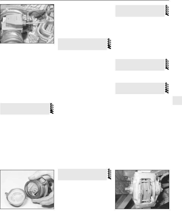
2 For a quick check, the thickness of friction material remaining on each pad can be measured through the slot in the front of the caliper body (see illustration). If any pad is worn to the minimum thickness or less, all four pads must be renewed (see Chapter 9).
3 For a complete check, the brake pads should be removed and cleaned. This will allow the operation of the caliper to be checked, and the condition of the brake disc itself to be fully examined on both sides (see Chapter 9).
Rear brakes
4 Chock the front wheels, then jack up the rear of the vehicle and support securely on axle stands; remove the roadwheels (see
“Jacking and Vehicle Support “). Inspect the pads as described in paragraphs 2 and 3.
12.2 Removing the fuel pump cover, filter and rubber seal - carburettor models
14 Electrical system check
1 Check the operation of all the electrical equipment, ie lights, direction indicators, horn, etc. Refer to the appropriate sections of Chapter 12 for details if any of the circuits are found to be inoperative.
2Note that stop-light switch adjustment is described in Chapter 9.
3Check all accessible wiring connectors, harnesses and retaining clips for security, and for signs of chafing or damage. Rectify any faults found.
17.2 The thickness of the brake pads are visible through the caliper aperture
1•14 Every 9000 miles
18 Rear wheel bearing adjustment
Refer to Chapter 10, Section 9.
19 Handbrake adjustment
Rear drum brake models
1Normal adjustment of the handbrake takes place automatically due to the self-adjusting mechanism of the rear brakes. To compensate for cable stretch, or after a new cable has been fitted or the adjustment has otherwise been disturbed, proceed as follows.
2Chock the front wheels, release the handbrake and raise and support the rear of the vehicle so that the rear wheels are clear of the ground.
3Tighten the nut on the handbrake cable yoke until the rear wheels start to become stiff to turn, then back it off until they are free again (see illustration).
4Check that the handbrake starts to take effect at the second notch of lever movement, and is fully applied by the fourth or fifth notch.
5A further check may be made by removing the plug in the brake backplate (see illustration). When adjustment is correct, the pin on the handbrake operating lever is clear
19.5 Check the handbrake lever pin (arrowed) is correctly positioned as described in text
the handbrake shoe adjuster wheel is accessible through the hole in the disc . . .
19.3 Handbrake cable adjusting nut (arrowed) on yoke - rear drum brake models
of the shoe web by approximately 3 mm with the handbrake released.
6 When adjustment is correct, apply a smear of grease to the threads of the cable end fitting to prevent corrosion. Lower the vehicle, apply the handbrake and remove the wheel chocks.
Rear disc brake models
7 Before checking handbrake adjustment, drive for approximately 300 metres at low speed with the handbrake lightly applied. This will clean off any rust or glaze from the drums and shoes.
8Chock the front wheels and engage a gear. Slacken the rear wheel bolts. Raise and support the rear of the vehicle and remove the rear wheels.
9Release the handbrake, then reapply it by two notches.
10Slacken off the adjuster nut on the handbrake cable yoke (located to the left of the silencer) until it is at the end of its travel. If a silencer heat shield is fitted, access will be improved by removing it.
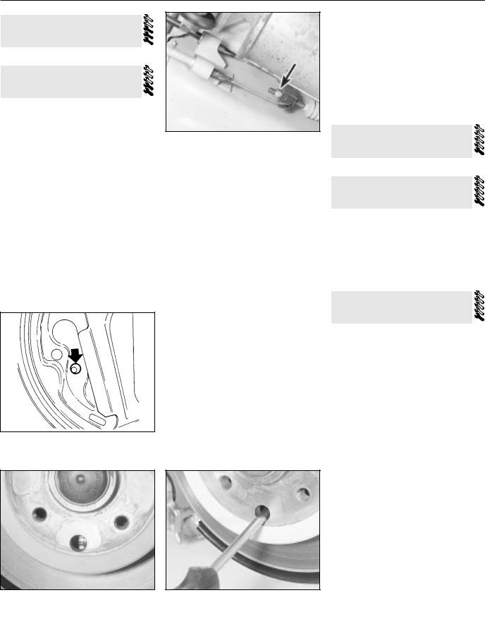
11Turn a brake disc to bring the adjuster hole (the large unthreaded hole) into line with the adjuster at the bottom of the brake shoes. Using a screwdriver through the hole, turn the adjuster wheel until the shoes are against the disc, then back it off again until the disc is just free to turn without the shoes dragging (see illustrations).
suitable screwdriver
12Repeat the operation on the other brake.
13Tighten the cable adjuster nut until the shoes start to drag again. This should happen on both sides.
14Release and fully reapply the handbrake a couple of times. Check that the discs turn freely when the control is fully released, and that the brake is fully applied at the sixth notch.
15Refit the exhaust heat shield if it was removed. Refit the wheels, lower the vehicle and tighten the wheel bolts.
20 Driveshaft CV joint and gaiter check
Refer to Chapter 8, Section 5.
21 Hinge and lock lubrication
Lubricate the hinges of the bonnet, doors and tailgate with a light general-purpose oil. Similarly, lubricate all latches, locks and lock strikers. At the same time, check the security and operation of all the locks, adjusting them if necessary (see Chapter 11).
Lightly lubricate the bonnet release mechanism and cable with a suitable grease.
22 Exhaust system check
1With the engine cold (at least an hour after the vehicle has been driven), check the complete exhaust system from the engine to the end of the tailpipe. The exhaust system is most easily checked with the vehicle raised on a hoist, or suitably supported on axle stands (see “Jacking and Vehicle Support”). so that the exhaust components are readily visible and accessible.
2Check the exhaust pipes and connections for evidence of leaks, severe corrosion and damage. Make sure that all brackets and mountings are in good condition, and that all relevant nuts and bolts are tight. Leakage at any of the joints or in other parts of the system will usually show up as a black sooty stain in the vicinity of the leak. Reputable exhaust repair systems can be used for effective repairs to exhaust pipes and silencer boxes, including ends and bends. Check for an MOTapproved permanent exhaust repair.
3Rattles and other noises can often be traced to the exhaust system, especially the brackets and mountings. Try to move the pipes and silencers. If the components are able to come into contact with the body or suspension parts, secure the system with new mountings. Otherwise separate the joints (if possible) and twist the pipes as necessary to provide additional clearance.

Every 18 000 miles 1•15
23 Road test
Instruments and electrical equipment
1Check the operation of all instruments and electrical equipment.
2Make sure that all instruments read correctly, and switch on all electrical equipment in turn, to check that it functions properly.
Steering and suspension
3Check for any abnormalities in the steering, suspension, handling or road “feel”.
4Drive the vehicle, and check that there are no unusual vibrations or noises.
5Check that the steering feels positive, with no excessive “sloppiness”, or roughness, and check for any suspension noises when cornering and driving over bumps.
Drivetrain
6 Check the performance of the engine, clutch (where applicable), gearbox/ transmission and driveshafts.
7 Listen for any unusual noises from the engine, clutch and gearbox/transmission.
8Make sure that the engine runs smoothly when idling, and that there is no hesitation when accelerating.
9Check that, where applicable, the clutch action is smooth and progressive, that the drive is taken up smoothly, and that the pedal travel is not excessive. Also listen for any noises when the clutch pedal is depressed.
10On manual gearbox models, check that all gears can be engaged smoothly without noise, and that the gear lever action is not abnormally vague or “notchy”.
11On automatic transmission models, make sure that all gearchanges occur smoothly, without snatching, and without an increase in engine speed between changes. Check that all the gear positions can be selected with the vehicle at rest. If any problems are found, they should be referred to a Vauxhall/Opel dealer.
12Listen for a metallic clicking sound from the front of the vehicle, as the vehicle is driven slowly in a circle with the steering on full-lock. Carry out this check in both directions. If a clicking noise is heard, this indicates wear in a driveshaft joint, in which case renew the joint if necessary.
Check the operation and performance of the braking system
13Make sure that the vehicle does not pull to one side when braking, and that the wheels do not lock prematurely when braking hard.
14Check that there is no vibration through the steering when braking.
15Check that the handbrake operates correctly without excessive movement of the lever, and that it holds the vehicle stationary on a slope.
16Test the operation of the brake servo unit as follows. With the engine off, depress the footbrake four or five times to exhaust the vacuum. Hold the brake pedal depressed, then start the engine. As the engine starts, there should be a noticeable “give” in the brake pedal as vacuum builds up. Allow the engine to run for at least two minutes, and then switch it off. If the brake pedal is depressed now, it should be possible to detect a hiss from the servo as the pedal is depressed. After about four or five applications, no further hissing should be heard, and the pedal should feel considerably harder.
1
Every 18 000 miles
24 Air cleaner filter element renewal
Carburettor models
1To remove the air cleaner element, remove the air cleaner cover. This is secured by a centre nut or bolt, or by three screws. Additionally, release the spring clips around the edge of the cover or, if spring clips are not fitted, carefully prise around the lower edge of the cover with your fingers to release the retaining lugs (see illustrations).
2With the cover removed, lift out the element
(see illustrations).
3Wipe inside the air cleaner, being careful not to introduce dirt into the carburettor throat. It is preferable to remove the air cleaner completely. Remember to clean the inside of the air cleaner cover.
4Fit the new element, then refit and secure the cover. Observe any cover-to-body alignment lugs or slots.
Fuel injection models
1.4 and 1.6 litre models
5 Refer to paragraphs 1 to 4.
1.8 and 2.0 litre 8-valve models
6 The air cleaner on these models is contained within the airflow sensor housing.
24.1a On carburettor models, undo the retaining nut (on some models the lid will be retained by screws) . . .
24.2a . . . then lift off the air cleaner lid . . .
24.1b . . . and release the retaining clips . . .
24.2b . . . and withdraw the filter element
1•16 Every 18 000 miles
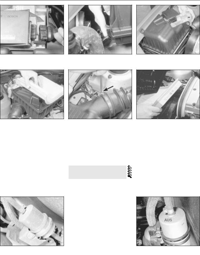
24.7 On 1.8 and 2.0 litre 8-valve models, disconnect the airflow sensor wiring connector . . .
24.9 On fitting, ensure the element is correctly seated in the cover groove
7 Release the locking clip, and disconnect the plug from the airflow sensor (see illustration). Disconnect the air trunking.
8Release the spring clips, and lift off the air cleaner cover with airflow sensor attached. The element will probably come away with the cover (see illustrations). Do not drop or jar the airflow sensor.
9Wipe clean the inside of the air cleaner an fit a new element to the cover, engaging the element seal in the cover recess (see illustration). Refit and secure the cover, then reconnect the airflow sensor plug. Refit the air trunking.
2.0 litre 16-valve models
10 Disconnect the trunking which connects
25.3 Fuel filter showing mounting and hose connections
24.8a . . . then release the retaining clips . . .
24.10 Disconnecting the trunking from the air cleaner - 2.0 litre 16-valve models
the air cleaner to the mass meter (see illustration).
11Release the four spring clips which secure the air cleaner lid. Remove the lid.
12Remove the element and wipe clean the inside of the filter housing and lid.
13Fit a new element, sealing lip uppermost (see illustration). Refit and secure the lid and trunking.
25 Fuel filter renewal - fuel injection models
Warning: Before carrying out the following operation refer to the precautions given in Safety first! and follow them implicitly.
Petrol is a highly dangerous and volatile liquid and the precautions necessary when handling it cannot be overstressed.
The fuel filter is located under the rear of the vehicle. Chock the front wheels, jack up the rear the vehicle, and support securely on axle
stands (see “Jacking and Vehicle Support“). Disconnect the battery negative lead and
position a suitable container below the fuel to catch spilt fuel.
Slacken the retaining clips and, bearing in the information given in Chapter 4B on depressurising the fuel system, disconnect hoses. To minimise fuel loss clamp the hoses either side of the filter or be prepared to
24.8b . . . and remove the air cleaner housing cover, complete with the filter element
24.13Fitting a new air cleaner element -
2.0litre 16-valve models
plug the hose ends as they are disconnected
(see illustration).
4Loosen the clamp bolt, and withdraw the filter from its clamp. Note the orientation of the fuel flow direction indicator on the filter. This will be in the form of an arrow which points in the direction of the fuel flow, or the filter will have AUS (out) stamped on its outlet side (see illustration).
5Recover the mounting rubber from the old filter, and transfer it to the new filter.
6Fit the new filter making sure its fuel flow direction indicator is facing the right way.
7Reconnect the hose and securely tighten their retaining clips.
8Start the engine and check the disturbed hose connections for signs of leakage.
25.4 Fuel filter directional marking
Every 18 000 miles 1•17
26 Carburettor fuel inlet filter cleaning
Warning: Before carrying out the following operation refer to the precautions given in Safety first! and follow them implicitly. Petrol
is a highly dangerous and volatile liquid and the precautions necessary when handling it cannot be overstressed.
Referring to the relevant Section of Chapter 4A, remove the filter, wash it fresh fuel to remove any debris from it. Inspect the filter for signs of clogging or splitting and renew it if necessary. Refit the filter and reconnect the fuel hose.
27 Manual transmission oil level check
1Ensure that the vehicle is standing on level ground and the handbrake applied.
2Working underneath the vehicle, unscrew the transmission oil level plug (see illustration). The level plug is located beside the driveshaft inner CV joint; on 1.2, 1.3, 1.4 and later 1.6 litre models the plug is on the left-hand side of the transmission, and on all other models it is on the right-hand side.
3The oil level should be up to the lower edge of the level plug hole.
4If necessary, top-up with oil through the breather/filler orifice in the gear selector cover. Unscrew the breather/filler plug, and top-up with the specified grade of oil, until oil just begins to run from the level plug hole. A funnel may be helpful, to avoid spillage (see illustrations). Do not overfill - if too much oil is added, wait until the excess has run out of the level plug hole. Refit the level plug and the breather/filler plug on completion.
28 Clutch adjustment check
Refer to Chapter 6
29 Rear brake shoe, wheel cylinder and drum check
1Chock the front wheels, then jack up the rear of the vehicle, and support it securely on axle stands (see “Jacking and Vehicle Support”).
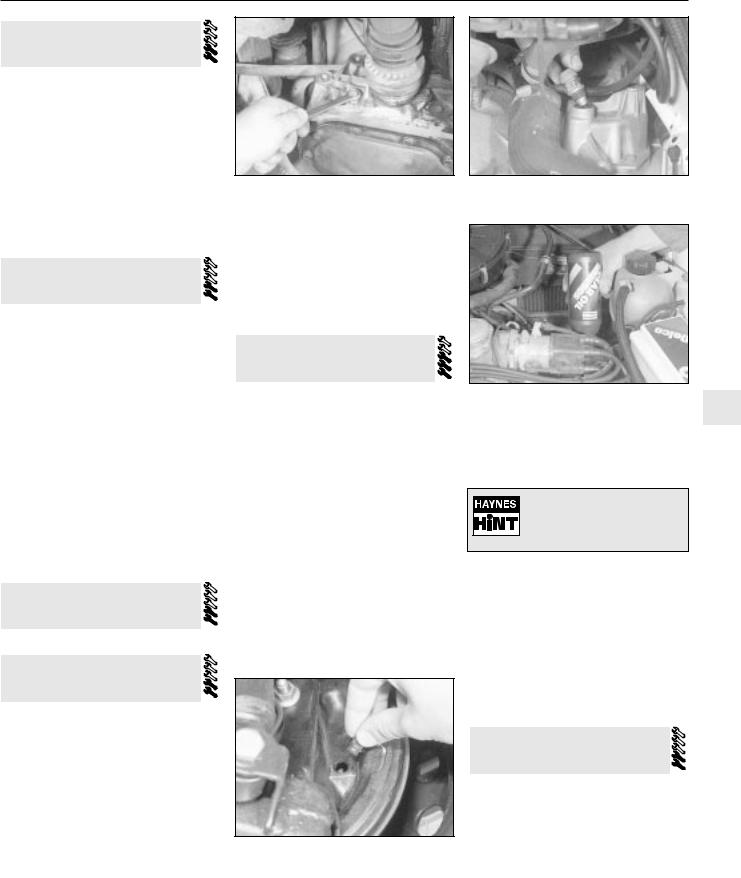
2For a quick check, the thickness of friction material remaining on one of the brake shoes can be observed through the hole in the brake backplate which is exposed by prising out the sealing grommet (see illustration). If a rod of the same diameter as the specified minimum friction material thickness is placed against the shoe friction material, the amount of wear can be assessed. A torch or inspection light
27.2 Removing the manual transmission level plug - early 1.6 litre model shown
will probably be required. If the friction material on any shoe is worn down to the specified minimum thickness or less, all four shoes must be renewed as a set.
3 For a comprehensive check, the brake drum should be removed and cleaned. This will allow the wheel cylinders to be checked, and the condition of the brake drum itself to be fully examined (see Chapter 9).
27.4a To top up, unscrew the breather/filler plug from the top of the transmission . . .
30 Brake fluid renewal
Warning: Brake hydraulic fluid can harm your eyes and damage painted surfaces, so use extreme caution when handling and pouring it. Do not use fluid
that has been standing open for some time as it absorbs moisture from the air. Excess moisture can cause a dangerous loss of braking effectiveness.
1 The procedure is similar to that for the bleeding of the hydraulic system as described in Chapter 9, except that the brake fluid reservoir should be emptied by siphoning, using a clean poultry baster or similar before starting, and allowance should be made for the old fluid to be expelled when bleeding a section of the circuit.
2 Working as described in Chapter 9, open the first bleed screw in the sequence and pump the brake pedal gently until nearly all the old fluid has been emptied from the master cylinder reservoir. Top-up to the `MAX’
27.4b . . . then top up via the breather/filler |
1 |
plug orifice |
level with new fluid and continue pumping until only the new fluid remains in the reservoir and new fluid can be seen emerging from the bleed screw. Tighten the screw and top the reservoir level up to the `MAX’ level line.
Old hydraulic fluid is invariably much darker in colour than the new, making it easy to distinguish the two.
3Work through all the remaining bleed screws in sequence until new fluid can be seen at all of them. Be careful to keep the master cylinder reservoir topped up to above the `MIN’ level at all times or air may enter the system and greatly increase the length of the task.
4When the operation is complete, check that all bleed screws are securely tightened and that their dust caps are refitted. Wash off all traces of spilt fluid and recheck the master cylinder reservoir fluid level.
5Check the operation of the brakes before taking the car on the road.
29.2 Removing the sealing grommet from the inspection hole in the rear brake backplate
31 Headlamp aim check
Accurate adjustment of the headlight beam is only possible using optical beam-setting equipment, and this work should therefore be carried out by a Vauxhall/Opel dealer or service station with the necessary facilities.
Basic adjustments can be carried out in an emergency, and further details are given in Chapter 12.
1•18 Maintenance procedures
Every 2 Years
32 Coolant renewal
Cooling system draining
Warning: Wait until the engine is cold before starting this procedure. Do not allow antifreeze to come in contact
with your skin or painted surfaces of the vehicle. Rinse off spills immediately with plenty of water. Never leave antifreeze lying around in an open container or in a puddle in the driveway or on the garage floor. Children and pets are attracted by its sweet smell. Antifreeze is fatal if ingested.
1 To drain the cooling system, remove the expansion tank filler cap. Turn the cap anticlockwise until it reaches the first stop. Wait until any pressure remaining in the system is released then push the cap down, turn it anticlockwise to the second stop and lift off.
2Position a suitable container beneath the radiator bottom hose union.
3Slacken the hose clip and ease the hose from the radiator stub. If the hose joint has not been disturbed for some time, it will be necessary to gently manipulate the hose to break the joint. Do not use excessive force, or the radiator stub could be damaged. Allow the coolant to drain into the container.
4As no cylinder block drain plug is fitted and the radiator bottom hose union may be situated halfway up the radiator, this may not fully drain the cooling system.
5If the coolant has been drained for a reason other than renewal, then provided it is clean and less than two years old, it can be re-used.
6Reconnect the hose and securely tighten its retaining clip on completion of draining.
Cooling system flushing
7If coolant renewal has been neglected, or if the antifreeze mixture has become diluted, then in time, the cooling system may gradually lose efficiency, as the coolant passages become restricted due to rust, scale deposits, and other sediment.
8The cooling system efficiency can be restored by flushing the system clean.
9The radiator should be flushed independently of the engine to avoid unnecessary contamination.
Radiator flushing
10To flush the radiator, drain the cooling system then proceed as follows.
11Slacken the retaining clips and disconnect the top and bottom hoses from the radiator.
12Insert a garden hose into the radiator top inlet. Direct a flow of clean water through the radiator, and continue flushing until clean water emerges from the radiator bottom outlet.
13If after a reasonable period, the water still does not run clear, the radiator can be flushed
32.19a On 1.2 litre models, bleed the cooling system through the cylinder head heater hose outlet
with a good proprietary cleaning agent. It is important that the manufacturers instructions are followed carefully. If the contamination is particularly bad, insert the hose in the radiator bottom outlet, and flush the radiator in reverse.
Engine flushing
14 To flush the engine, remove the thermostat as described in Chapter 3, then temporarily refit the thermostat cover.
15 With the top and bottom hoses disconnected from the radiator, insert a garden hose into the radiator top hose. Direct a clean flow of water through the engine, and continue flushing until clean water emerges from the radiator bottom hose.
16 On completion of flushing, refit the thermostat and reconnect the hoses with reference to Chapter 3.
Cooling system filling
17Before attempting to fill the cooling system, make sure that all hoses and clips are in good condition, and that the clips are tight. Note that an antifreeze mixture must be used all year round, to prevent corrosion of the engine components (see following sub-Section). Also check that the radiator and cylinder block drain plugs are in place and tight.
18Remove the expansion tank filler cap.
19On 1.2 litre models, disconnect the heater hose from the cylinder head, on 1.3, 1.4 and later 1.6 litre engines models, disconnect the wire and unscrew the coolant temperature sender from the inlet manifold. On early 1.6, and all 1.8 and 2.0 litre models, unscrew the bleed screw which is situated in the thermostat housing cover (where no bleed screw is fitted, unscrew the temperature sender unit) (see illustrations).
20Fill the system by slowly pouring the coolant into the expansion tank to prevent airlocks from forming.
21If the coolant is being renewed, begin by pouring in a couple of litres of water, followed by the correct quantity of antifreeze, then topup with more water.
22When coolant free of air bubbles emerges from the orifice, reconnect the heater hose (1.2 litre models) or refit the coolant temperature
32.19b On 1.3 litre models, unscrew temperature gauge sender unit from the manifold to bleed the cooling system
sender/bleed screw (as applicable) and tighten it securely (all other models).
23Top-up the coolant level to the “KALT” (or “COLD”) mark on the expansion tank, then refit the expansion tank cap.
24Start the engine and run it until it reaches normal operating temperature, then stop the engine and allow it to cool.
25Check for leaks, particularly around disturbed components. Check the coolant level in the expansion tank, and top-up if necessary. Note that the system must be cold before an accurate level is indicated in the expansion tank. If the expansion tank cap is removed while the engine is still warm, cover the cap with a thick cloth, and unscrew the cap slowly to gradually relieve the system pressure (a hissing sound will normally be heard). Wait until any pressure remaining in the system is released, then continue to turn the cap until it can be removed.
Antifreeze mixture
26The antifreeze should always be renewed at the specified intervals. This is necessary not only to maintain the antifreeze properties, but also to prevent corrosion which would otherwise occur as the corrosion inhibitors become progressively less effective.
27Always use an ethylene-glycol based antifreeze which is suitable for use in mixed metal cooling systems. The quantity of antifreeze and levels of protection are indicated in the Specifications.
28Before adding antifreeze the cooling system should be completely drained, preferably flushed, and all hoses checked for condition and security.
29After filling with antifreeze, a label should be attached to the expansion tank stating the type and concentration of antifreeze used and the date installed. Any subsequent topping up should be made with the same type and concentration of antifreeze.
30Do not use engine antifreeze in the screen washer system, as it will cause damage to the vehicle paintwork. A proprietry screen should be added to the washer system in the recommended quantities.

Maintenance procedures 1•19
Every 36 000 miles
33 Automatic transmission fluid renewal
1Allow the transmission to cool down before draining, as the fluid: can be very hot indeed.
2Remove all the fluid pan screws except one which should be unscrewed through several turns.
3Release the fluid pan from its gasket and as the end of the pan tilts downwards, catch the
fluid in a suitable container.
4Remove the remaining screw and the pan. Peel off the gasket (where fitted) or remove all traces of sealant (as applicable).
5Pull the filter mesh from its securing clips and recover its sealing ring. Clean the filter in a high flash-point solvent and allow it to dry. If the filter is clogged or split it must be renewed.
6Fit a new O-ring and refit the filter securely.
7Ensure that the fluid pan and transmission
mating surfaces are clean and dry and bolt on the fluid pan using a new gasket. Where no gasket is fitted, apply a bead of sealant about 5.0 mm thick to clean surfaces. The fluid pan which is fitted with a gasket can be identified by the strengthening ribs on the pan flanges. The pan for use with silicone sealant has plain flanges.
8 Fill the transmission with the specified quantity of fluid and then check the level as described in Section 13.
Specifications |
|
|
|
|
Cooling system |
|
|
|
|
Antifreeze mixtures: |
|
|
|
|
Protection down to -15ºC . . . . . . . . . . . . . . . . . . . . . . . . . . . . . . . . . . |
28% antifreeze |
|
|
|
Protection down to -30ºC . . . . . . . . . . . . . . . . . . . . . . . . . . . . . . . . . . |
50% antifreeze |
|
|
|
Note: Refer to antifreeze manufacturer for latest recommendation |
|
|
|
|
Fuel system |
|
|
|
|
Idle speed: |
|
|
|
|
Carburettor models: |
|
|
|
|
Manual transmission . . . . . . . . . . . . . . . . . . . . . . . . . . . . . . . . . . . . |
900 to 950 rpm |
|
|
|
Automatic transmission . . . . . . . . . . . . . . . . . . . . . . . . . . . . . . . . . |
800 to 850 rpm |
|
|
|
Fuel-injected models: |
|
|
|
|
1.4 litre models . . . . . . . . . . . . . . . . . . . . . . . . . . . . . . . . . . . . . . . . |
830 to 990 rpm* |
|
|
1 |
1.6 litre models . . . . . . . . . . . . . . . . . . . . . . . . . . . . . . . . . . . . . . . . |
720 to 880 rpm* |
|
|
|
1.8 litre models: |
|
|
|
|
|
|
|
|
|
Early (pre 1987) models: |
|
|
|
|
Manual transmission . . . . . . . . . . . . . . . . . . . . . . . . . . . . . . . . |
900 to 950 rpm |
|
|
|
Automatic transmission . . . . . . . . . . . . . . . . . . . . . . . . . . . . . . |
800 to 850 rpm |
|
|
|
Later (1987 onwards) models . . . . . . . . . . . . . . . . . . . . . . . . . . . |
800 to 900 rpm |
|
|
|
2.0 litre models . . . . . . . . . . . . . . . . . . . . . . . . . . . . . . . . . . . . . . . . |
720 to 780 rpm* |
|
|
|
Idle mixture CO content: |
|
|
|
|
Carburettor models . . . . . . . . . . . . . . . . . . . . . . . . . . . . . . . . . . . . . . . |
1.0 to 1.5% |
|
|
|
Fuel-injected models . . . . . . . . . . . . . . . . . . . . . . . . . . . . . . . . . . . . . |
Less than 1.0%** |
|
|
|
*Not adjustable - controlled by ECU |
|
|
|
|
**On all 1.4 and 1.6 litre fuel injection models, and 2.0 litre models with a catalytic converter the exhaust gas CO content is regulated by the |
|
|||
control unit and is not adjustable |
|
|
|
|
Ignition system |
|
|
|
|
Spark plugs: |
|
|
|
|
Type: |
|
|
|
|
1.2 litre models . . . . . . . . . . . . . . . . . . . . . . . . . . . . . . . . . . . . . . . . |
Champion RL82YCC or RL82YC |
|
||
1.3, 1.4, 1.6 and 1.8 litre models . . . . . . . . . . . . . . . . . . . . . . . . . . |
Champion RN9YCC or RN9YC |
|
||
2.0 litre models: |
|
|
|
|
8-valve models . . . . . . . . . . . . . . . . . . . . . . . . . . . . . . . . . . . . . . |
Champion RN9YCC or RN9YC |
|
||
16-valve models . . . . . . . . . . . . . . . . . . . . . . . . . . . . . . . . . . . . . |
Champion RC9MCC |
|
|
|
Electrode gap: |
|
|
|
|
RL82YCC, RN9YCC and RC9MCC plugs . . . . . . . . . . . . . . . . . . . |
0.8 mm |
|
|
|
RL82YC and RN9YC plugs . . . . . . . . . . . . . . . . . . . . . . . . . . . . . . . |
0.7 mm |
|
|
|
*The spark plug gap quoted is that recommended by Champion for their specified plugs listed above. If spark plugs of any other type are to be |
|
|||
fitted, refer to their manufacturer’s spark plug gap recommendations. |
|
|
|
|
HT leads . . . . . . . . . . . . . . . . . . . . . . . . . . . . . . . . . . . . . . . . . . . . . . . . . |
Champion type not available |
|
||
Braking system |
|
|
|
|
Brake pad minimum thickness (including backing plate) . . . . . . . . . . . . |
7.0 mm |
|
|
|
Rear brake shoe minimum friction material-to-rivet head depth . . . . . . |
0.5 mm |
|
|
|
Torque wrench settings |
Nm |
lbf ft |
|
|
Sump drain plug . . . . . . . . . . . . . . . . . . . . . . . . . . . . . . . . . . . . . . . . . . . |
45 |
33 |
|
|
Spark plugs . . . . . . . . . . . . . . . . . . . . . . . . . . . . . . . . . . . . . . . . . . . . . . . |
20 |
15 |
|
|
Roadwheel bolts . . . . . . . . . . . . . . . . . . . . . . . . . . . . . . . . . . . . . . . . . . . |
90 |
66 |
|
|
|
|
|
|
|

2A•1
Chapter 2 Part A:
OHV engine
Contents |
|
|
Ancillary components - removal and refitting . . . . . |
. . . . |
. . . . . . . . . . .6 |
Camshaft and tappets - removal and refitting . . . . |
. . . . |
. . . . . . . . . .18 |
Compression test - description and interpretation . |
. . . . |
. . . . . . . . . . .2 |
Crankshaft and main bearings - removal and refitting . |
. . . . . . . . . .20 |
|
Crankshaft rear oil seal - removal and refitting . . . |
. . . . |
. . . . . . . . . .19 |
Cylinder head - overhaul . . . . . . . . . . . . . . . . . . . . |
. . . . |
. . . . . . . . . . .9 |
Cylinder head - removal and refitting . . . . . . . . . . |
. . . . |
. . . . . . . . . . .8 |
Cylinder head and pistons - decarbonising . . . . . . |
. . . . |
. . . . . . . . . .10 |
Engine oil and filter - renewal . . . . . . . . . . . . . . . . . |
. . . . |
See Chapter 1 |
Engine oil level check . . . . . . . . . . . . . . . . . . . . . . . |
See Weekly checks |
|
Engine - initial start-up after overhaul . . . . . . . . . . |
. . . . |
. . . . . . . . . .24 |
Engine - removal and refitting . . . . . . . . . . . . . . . . |
. . . . |
. . . . . . . . . .23 |
Engine components - examination and renovation |
. . . . |
. . . . . . . . . .21 |
Engine dismantling and reassembly - general . . . . |
. . . . |
. . . . . . . . . . .5 |
Engine lubrication system - general description . . . . . . |
. . . . . . . . . .22 |
Engine/transmission mountings - removal and refitting |
. . . . . . . . . .17 |
Flywheel - removal and refitting . . . . . . . . . . . . . . . . . . |
. . . . . . . . . .16 |
General description . . . . . . . . . . . . . . . . . . . . . . . . . . . . |
. . . . . . . . . . .1 |
General engine checks . . . . . . . . . . . . . . . . . . . . . . . . . . |
See Chapter 1 |
Oil pump - overhaul . . . . . . . . . . . . . . . . . . . . . . . . . . . . |
. . . . . . . . . .13 |
Oil pump - removal and refitting . . . . . . . . . . . . . . . . . . |
. . . . . . . . . .12 |
Operations possible with the engine in the car . . . . . . . |
. . . . . . . . . . .3 |
Operations requiring engine removal . . . . . . . . . . . . . . |
. . . . . . . . . . .4 |
Pistons and connecting rods - removal and refitting . . |
. . . . . . . . . .15 |
Sump - removal and refitting . . . . . . . . . . . . . . . . . . . . . |
. . . . . . . . . .11 |
Timing gear components - removal and refitting . . . . . |
. . . . . . . . . .14 |
Valve clearances - adjustment . . . . . . . . . . . . . . . . . . . |
. . . . . . . . . . .7 |
Degrees of difficulty
Easy, suitable for |
Fairly easy, suitable |
Fairly difficult, |
Difficult, suitable for |
Very difficult, |
novice with little |
for beginner with |
suitable for competent |
experienced DIY |
suitable for expert |
experience |
some experience |
DIY mechanic |
mechanic |
DIY or professional |
Specifications
General |
|
2A |
|
|
|
Maker’s designation . . . . . . . . . . . . . . . . . . . . . . . . . . . . . . . . . . . . . . . . |
12 SC |
|
Bore x stroke . . . . . . . . . . . . . . . . . . . . . . . . . . . . . . . . . . . . . . . . . . . . . |
79.0 x 61.0 mm |
|
Cubic capacity . . . . . . . . . . . . . . . . . . . . . . . . . . . . . . . . . . . . . . . . . . . . |
1196 cc |
|
Compression ratio . . . . . . . . . . . . . . . . . . . . . . . . . . . . . . . . . . . . . . . . . |
9.0: 1 |
|
Valve clearances (warm) |
|
|
Inlet . . . . . . . . . . . . . . . . . . . . . . . . . . . . . . . . . . . . . . . . . . . . . . . . . . . . . |
0.15 mm |
|
Exhaust . . . . . . . . . . . . . . . . . . . . . . . . . . . . . . . . . . . . . . . . . . . . . . . . . . |
0.25 mm |
|
Cylinder head |
|
|
Identification mark . . . . . . . . . . . . . . . . . . . . . . . . . . . . . . . . . . . . . . . . . |
E |
|
Valve seat width: |
|
|
Inlet . . . . . . . . . . . . . . . . . . . . . . . . . . . . . . . . . . . . . . . . . . . . . . . . . . . |
1.25 to 1.50 mm |
|
Exhaust . . . . . . . . . . . . . . . . . . . . . . . . . . . . . . . . . . . . . . . . . . . . . . . . |
1.60 to 1.85 mm |
|
Overall height . . . . . . . . . . . . . . . . . . . . . . . . . . . . . . . . . . . . . . . . . . . . . |
81 ± 0.25 mm |
|
Valves and guides |
Inlet |
Exhaust |
Overall length . . . . . . . . . . . . . . . . . . . . . . . . . . . . . . . . . . . . . . . . . . . . . |
99.3 mm |
101.1 mm |
Head diameter . . . . . . . . . . . . . . . . . . . . . . . . . . . . . . . . . . . . . . . . . . . . |
32 mm |
29 mm |
Stem diameter (nominal, ± 0.005 mm): |
|
|
Standard . . . . . . . . . . . . . . . . . . . . . . . . . . . . . . . . . . . . . . . . . . . . . . . |
7.005 mm |
6.995 mm |
Oversize 1 . . . . . . . . . . . . . . . . . . . . . . . . . . . . . . . . . . . . . . . . . . . . . . |
7.080 mm |
7.060 mm |
Oversize 2 . . . . . . . . . . . . . . . . . . . . . . . . . . . . . . . . . . . . . . . . . . . . . . |
7.155 mm |
7.1 35 mm |
Oversize A . . . . . . . . . . . . . . . . . . . . . . . . . . . . . . . . . . . . . . . . . . . . . . |
7.255 mm |
7.235 mm |
Valve guide bore (± 0.01 mm): |
|
|
Standard . . . . . . . . . . . . . . . . . . . . . . . . . . . . . . . . . . . . . . . . . . . . . . . |
7.035 mm |
|
Oversize 1 . . . . . . . . . . . . . . . . . . . . . . . . . . . . . . . . . . . . . . . . . . . . . . |
7.110 mm |
|
Oversize 2 . . . . . . . . . . . . . . . . . . . . . . . . . . . . . . . . . . . . . . . . . . . . . . |
7.185 mm |
|
Oversize A . . . . . . . . . . . . . . . . . . . . . . . . . . . . . . . . . . . . . . . . . . . . . . |
7.285 mm |
|
Valve clearance in guide: |
|
|
Inlet . . . . . . . . . . . . . . . . . . . . . . . . . . . . . . . . . . . . . . . . . . . . . . . . . . . |
0.01 5 to 0.045 mm |
|
Exhaust . . . . . . . . . . . . . . . . . . . . . . . . . . . . . . . . . . . . . . . . . . . . . . . . |
0.035 to 0.065 mm |
|
Sealing face angle . . . . . . . . . . . . . . . . . . . . . . . . . . . . . . . . . . . . . . . . . |
44° |
|
2A•2 OHV engine
Camshaft
Radial run-out . . . . . . . . . . . . . . . . . . . . . . . . . . . . . . . . . . . . . . . . . . . . . |
0.03 mm max |
|
Endfloat . . . . . . . . . . . . . . . . . . . . . . . . . . . . . . . . . . . . . . . . . . . . . . . . . . |
0.17 to 0.43 mm |
|
Cam lift . . . . . . . . . . . . . . . . . . . . . . . . . . . . . . . . . . . . . . . . . . . . . . . . . . |
6.45 mm |
|
Pistons and bores |
Diameters |
Marking |
Production size 1 . . . . . . . . . . . . . . . . . . . . . . . . . . . . . . . . . . . . . . . . . . |
78.95 mm |
5 |
|
78.96 mm |
6 |
|
78.97 mm |
7 |
|
78.98 mm |
8 |
Production size 2 . . . . . . . . . . . . . . . . . . . . . . . . . . . . . . . . . . . . . . . . . . |
78.99 mm |
99 |
|
79.00 mm |
00 |
|
79.01 mm |
01 |
|
79.02 mm |
02 |
Production size 3 . . . . . . . . . . . . . . . . . . . . . . . . . . . . . . . . . . . . . . . . . . |
79.03 mm |
03 |
|
79.04 mm |
04 |
|
79.05 mm |
05 |
|
79.06 mm |
06 |
Production size 4 . . . . . . . . . . . . . . . . . . . . . . . . . . . . . . . . . . . . . . . . . . |
79.07 mm |
07 |
|
79.08 mm |
08 |
|
79.09 mm |
09 |
|
79.10 mm |
1 |
Oversize (+0.5 mm nominal) . . . . . . . . . . . . . . . . . . . . . . . . . . . . . . . . . . |
79.47 mm |
79.47/7 +0.5 |
|
79.48 mm |
79.48/8 +0.5 |
|
79.49 mm |
79.49/9 +0.5 |
|
79.50 mm |
79.50/0 + 0.5 |
Pistons clearance in bore . . . . . . . . . . . . . . . . . . . . . . . . . . . . . . . . . . . . |
0.1 to 0.3 mm estimated |
|
Bore out-of-round and taper . . . . . . . . . . . . . . . . . . . . . . . . . . . . . . . . . |
0.013 mm max |
|
Piston rings |
|
|
Quantity (per piston) . . . . . . . . . . . . . . . . . . . . . . . . . . . . . . . . . . . . . . . . |
2 compression, 1 oil control (scraper) |
|
Thickness: |
|
|
Compression . . . . . . . . . . . . . . . . . . . . . . . . . . . . . . . . . . . . . . . . . . . . |
2.0 mm |
|
Oil control . . . . . . . . . . . . . . . . . . . . . . . . . . . . . . . . . . . . . . . . . . . . . . |
5.0 mm |
|
End gap: |
|
|
Compression . . . . . . . . . . . . . . . . . . . . . . . . . . . . . . . . . . . . . . . . . . . . |
0.30 to 0.45 mm |
|
Oil control . . . . . . . . . . . . . . . . . . . . . . . . . . . . . . . . . . . . . . . . . . . . . . |
0.40 to 1.40 mm |
|
Ring gap offset . . . . . . . . . . . . . . . . . . . . . . . . . . . . . . . . . . . . . . . . . . . . |
180° (see text) |
|
Ring vertical clearance in groove . . . . . . . . . . . . . . . . . . . . . . . . . . . . . . |
Not specified - typically 0.06 mm |
|
Gudgeon pins |
|
|
Length . . . . . . . . . . . . . . . . . . . . . . . . . . . . . . . . . . . . . . . . . . . . . . . . . . . |
65 mm |
|
Diameter . . . . . . . . . . . . . . . . . . . . . . . . . . . . . . . . . . . . . . . . . . . . . . . . . |
20 mm |
|
Clearance in piston . . . . . . . . . . . . . . . . . . . . . . . . . . . . . . . . . . . . . . . . . |
0.0015 to 0.0195 mm |
|
Clearance in connecting rod . . . . . . . . . . . . . . . . . . . . . . . . . . . . . . . . . . |
None (interference fit) |
|
Crankshaft and bearings |
|
|
Number of main bearings . . . . . . . . . . . . . . . . . . . . . . . . . . . . . . . . . . . . |
3 |
|
Main bearing journal diameters - standard: |
|
|
Front . . . . . . . . . . . . . . . . . . . . . . . . . . . . . . . . . . . . . . . . . . . . . . . . . . |
53.997 to 54.010 mm |
|
Centre and rear . . . . . . . . . . . . . . . . . . . . . . . . . . . . . . . . . . . . . . . . . . |
54.007 to 54.020 mm |
|
Centre journal width - standard . . . . . . . . . . . . . . . . . . . . . . . . . . . . . . . |
29.000 to 29.052 mm |
|
Main bearing shell identification - standard: |
Colour code |
Embossed code |
Front, top . . . . . . . . . . . . . . . . . . . . . . . . . . . . . . . . . . . . . . . . . . . . . . |
Brown |
1 ON or 701-N |
Front, bottom . . . . . . . . . . . . . . . . . . . . . . . . . . . . . . . . . . . . . . . . . . . |
Brown |
1 UN or 702-N |
Centre, top . . . . . . . . . . . . . . . . . . . . . . . . . . . . . . . . . . . . . . . . . . . . . |
Brown |
20+UN or 705-N |
Centre, bottom . . . . . . . . . . . . . . . . . . . . . . . . . . . . . . . . . . . . . . . . . . |
Green |
20+UN or 725-N |
Rear, top . . . . . . . . . . . . . . . . . . . . . . . . . . . . . . . . . . . . . . . . . . . . . . . |
Green |
631-N |
Rear, bottom . . . . . . . . . . . . . . . . . . . . . . . . . . . . . . . . . . . . . . . . . . . . |
Green |
635-N |
Main bearing shell identification - standard journal, oversize housing: |
|
|
Front, top . . . . . . . . . . . . . . . . . . . . . . . . . . . . . . . . . . . . . . . . . . . . . . |
U1 -OB |
|
Front, bottom . . . . . . . . . . . . . . . . . . . . . . . . . . . . . . . . . . . . . . . . . . . |
U1-U |
|
Centre, top and bottom . . . . . . . . . . . . . . . . . . . . . . . . . . . . . . . . . . . |
U |
|
Rear, top . . . . . . . . . . . . . . . . . . . . . . . . . . . . . . . . . . . . . . . . . . . . . . . |
U3-OB |
|
Rear, bottom . . . . . . . . . . . . . . . . . . . . . . . . . . . . . . . . . . . . . . . . . . . . |
U3-U |
|
Big-end bearing journal diameter - standard . . . . . . . . . . . . . . . . . . . . . |
4.971 to 44.987 mm |
|
Big-end bearing shell identification - standard . . . . . . . . . . . . . . . . . . . . |
None |
|
Main and big-end bearing undersizes . . . . . . . . . . . . . . . . . . . . . . . . . . |
0.25 mm production and service; 0.50 mm service only |
|

OHV engine 2A•3
Main bearing shell identification - 0.25 undersize: |
Colour code |
Embossed code |
|
Front, top . . . . . . . . . . . . . . . . . . . . . . . . . . . . . . . . . . . . . . . . . . . . . . |
Brown-blue |
1 |
OA or 006-A |
Front, bottom . . . . . . . . . . . . . . . . . . . . . . . . . . . . . . . . . . . . . . . . . . . |
Brown-blue |
1 |
UA or 008-A |
Centre, top . . . . . . . . . . . . . . . . . . . . . . . . . . . . . . . . . . . . . . . . . . . . . |
Brown-blue |
20+UA or 014-A |
|
Centre, bottom . . . . . . . . . . . . . . . . . . . . . . . . . . . . . . . . . . . . . . . . . . |
Brown |
20+UA or 034-A |
|
Rear, top . . . . . . . . . . . . . . . . . . . . . . . . . . . . . . . . . . . . . . . . . . . . . . . |
Green-blue |
632-A |
|
Rear, bottom . . . . . . . . . . . . . . . . . . . . . . . . . . . . . . . . . . . . . . . . . . . . |
Green-blue |
636-A |
|
Main bearing shell identification - 0.50 undersize: |
|
|
|
Front, top . . . . . . . . . . . . . . . . . . . . . . . . . . . . . . . . . . . . . . . . . . . . . . |
Brown-black |
1 |
OB or 027 B |
Front, bottom . . . . . . . . . . . . . . . . . . . . . . . . . . . . . . . . . . . . . . . . . . . |
Brown-black |
1 |
U or 029 B |
Centre, top . . . . . . . . . . . . . . . . . . . . . . . . . . . . . . . . . . . . . . . . . . . . . |
Brown-black |
2 |
OB 0.35 B |
Centre, bottom . . . . . . . . . . . . . . . . . . . . . . . . . . . . . . . . . . . . . . . . . . |
Green-black |
2 |
UB 035 B |
Rear, top . . . . . . . . . . . . . . . . . . . . . . . . . . . . . . . . . . . . . . . . . . . . . . . |
None |
3 |
OB 0,50 |
Rear, bottom . . . . . . . . . . . . . . . . . . . . . . . . . . . . . . . . . . . . . . . . . . . . |
None |
3 |
U 0,50 |
Big-end bearing shell identification: |
|
|
|
0.25 undersize . . . . . . . . . . . . . . . . . . . . . . . . . . . . . . . . . . . . . . . . . . . |
A |
|
|
0.50 undersize . . . . . . . . . . . . . . . . . . . . . . . . . . . . . . . . . . . . . . . . . . . |
B |
|
|
Main and big-end bearing journal out-of-round . . . . . . . . . . . . . . . . . . . |
0.006 mm max |
|
|
Main and big-end bearing journal taper . . . . . . . . . . . . . . . . . . . . . . . . . |
0.01 mm max |
|
|
Crankshaft endfloat . . . . . . . . . . . . . . . . . . . . . . . . . . . . . . . . . . . . . . . . |
0.09 to 0.20 mm |
|
|
Connecting rod endfloat . . . . . . . . . . . . . . . . . . . . . . . . . . . . . . . . . . . . . |
0.02 to 0.06 mm |
|
|
Main bearing running clearance: |
|
|
|
Front . . . . . . . . . . . . . . . . . . . . . . . . . . . . . . . . . . . . . . . . . . . . . . . . . . |
0.020 to 0.046 mm |
|
|
Centre . . . . . . . . . . . . . . . . . . . . . . . . . . . . . . . . . . . . . . . . . . . . . . . . . |
0.010 to 0.036 mm |
|
|
Rear . . . . . . . . . . . . . . . . . . . . . . . . . . . . . . . . . . . . . . . . . . . . . . . . . . . |
0.01 0 to 0.032 mm estimated |
||
Big-end bearing running clearance . . . . . . . . . . . . . . . . . . . . . . . . . . . . |
0.11 to 0.24 mm |
|
|
Crankshaft radial run-out (at centre journal, shaft in block) . . . . . . . . . . |
0.03 mm max |
|
|
Flywheel
Ring gear run-out . . . . . . . . . . . . . . . . . . . . . . . . . . . . . . . . . . . . . . . . . . |
0.5 mm max |
Refinishing limit - depth of material which may be removed from |
|
clutch friction surface . . . . . . . . . . . . . . . . . . . . . . . . . . . . . . . . . . . . . |
0.3 mm max |
Lubrication system
Oil pump tolerances: |
|
2A |
Teeth backlash . . . . . . . . . . . . . . . . . . . . . . . . . . . . . . . . . . . . . . . . . . |
0.1 to 0.2 mm |
|
Teeth projection . . . . . . . . . . . . . . . . . . . . . . . . . . . . . . . . . . . . . . . . . |
0.04 to 0.10 mm |
|
Oil pressure at idle (engine warm) . . . . . . . . . . . . . . . . . . . . . . . . . . . . . |
1.5 bar |
|
Torque wrench settings |
Nm |
lbf ft |
Flywheel bolts (Use new bolts every time): |
|
|
Stage 1 . . . . . . . . . . . . . . . . . . . . . . . . . . . . . . . . . . . . . . . . . . . . . . . . |
35 |
26 |
Stage 2 . . . . . . . . . . . . . . . . . . . . . . . . . . . . . . . . . . . . . . . . . . . . . . . . |
Angle-tighten a further 50° to 90° |
|
Main bearing caps . . . . . . . . . . . . . . . . . . . . . . . . . . . . . . . . . . . . . . . . . |
62 |
46 |
Big-end bearing caps . . . . . . . . . . . . . . . . . . . . . . . . . . . . . . . . . . . . . . . |
27 |
20 |
Sump bolts (with locking compound) . . . . . . . . . . . . . . . . . . . . . . . . . . . |
5 |
4 |
Cylinder head bolts (use new bolts every time): |
|
|
Stage 1 . . . . . . . . . . . . . . . . . . . . . . . . . . . . . . . . . . . . . . . . . . . . . . . . |
25 |
18 |
Stage 2 . . . . . . . . . . . . . . . . . . . . . . . . . . . . . . . . . . . . . . . . . . . . . . . . |
Angle-tighten a further 60° |
|
Stage 3 . . . . . . . . . . . . . . . . . . . . . . . . . . . . . . . . . . . . . . . . . . . . . . . . |
Angle-tighten a further 60° |
|
Stage 4 . . . . . . . . . . . . . . . . . . . . . . . . . . . . . . . . . . . . . . . . . . . . . . . . |
Angle-tighten a further 60° |
|
Camshaft sprocket . . . . . . . . . . . . . . . . . . . . . . . . . . . . . . . . . . . . . . . . . |
40 |
30 |
Crankshaft pulley . . . . . . . . . . . . . . . . . . . . . . . . . . . . . . . . . . . . . . . . . . |
40 |
30 |
Engine mounting bracket, RH: |
|
|
To block (use sealant on lower bolt) . . . . . . . . . . . . . . . . . . . . . . . . . . |
20 |
15 |
To damping pad . . . . . . . . . . . . . . . . . . . . . . . . . . . . . . . . . . . . . . . . . |
40 |
30 |
Engine mountings to body: |
|
|
LH rear . . . . . . . . . . . . . . . . . . . . . . . . . . . . . . . . . . . . . . . . . . . . . . . . |
65 |
48 |
RH rear . . . . . . . . . . . . . . . . . . . . . . . . . . . . . . . . . . . . . . . . . . . . . . . . |
40 |
30 |
Sump drain plug . . . . . . . . . . . . . . . . . . . . . . . . . . . . . . . . . . . . . . . . . . . |
45 |
33 |
Oil pump mounting bolts . . . . . . . . . . . . . . . . . . . . . . . . . . . . . . . . . . . . |
20 |
15 |
1 General description
The engine is of four-cylinder. in-line overhead valve type, mounted transversely at the front of the car.
The crankshaft is supported in three shell type main bearings. Thrustwashers are incorporated in the centre main bearing to control crankshaft endfloat.
The connecting rods are attached to the crankshaft by horizontally split shell type big-end bearings. and to the pistons by
gudgeon pins which are an interference fit in the connecting rod small-end bore. The aluminium alloy pistons are of the slipper type and are fitted with three piston rings: two compression rings and an oil control ring.
The camshaft is chain driven from the crankshaft and operates the rocker arms via

2A•4 OHV engine
tappets and short pushrods. The inlet and exhaust valves are each closed by a single valve spring and operates in guides, integral with the cylinder head. The valves are actuated directly by the rocker arms.
Engine lubrication is by a gear type oil pump. The pump is mounted beneath the crankcase and is driven by a camshaft, as are the distributor and fuel pump.
Many of the engine component retaining bolts are of the socket-headed type and require the use of Torx type multi-tooth keys or socket bits for removal. These are readily available from retail outlets and should be obtained if major dismantling or repair work is to be carried out on the engine.
2 Compression test - description and interpretation
1 When engine performance is down, or if misfiring occurs which cannot be attributed to the ignition or fuel systems, a compression test can provide diagnostic clues as to the engine’s condition. If the test is performed regularly, it can give warning of trouble before any other symptoms become apparent.
2The engine must be fully warmed-up to normal operating temperature, the battery must be fully charged, and all the spark plugs must be removed (Chapter 1). The aid of an assistant will also be required.
3Disable the ignition system by disconnecting the ignition HT coil lead from the distributor cap and earthing it on the cylinder block. Use a jumper lead or similar wire to make a good connection.
4Fit a compression tester to the No 1 cylinder spark plug hole - the type of tester which screws into the plug thread is best.
5Have the assistant hold the throttle wide open, and crank the engine on the starter motor; after one or two revolutions, the compression pressure should build up to a maximum figure, and then stabilise. Record the highest reading obtained.
6Repeat the test on the remaining cylinders, recording the pressure in each.
7All cylinders should produce very similar pressures; a difference of more than 2 bars between any two cylinders indicates a fault. Note that the compression should build up quickly in a healthy engine; low compression on the first stroke, followed by graduallyincreasing pressure on successive strokes, indicates worn piston rings. A low compression reading on the first stroke, which does not build up during successive strokes, indicates leaking valves or a blown head gasket (a cracked head could also be the cause). Deposits on the undersides of the valve heads can also cause low compression.
8Although Vauxhall do not specify exact compression pressures, as a guide, any cylinder pressure of below 10 bars can be considered as less than healthy. Refer to a Vauxhall dealer or other specialist if in doubt
as to whether a particular pressure reading is acceptable.
9If the pressure in any cylinder is low, carry out the following test to isolate the cause. Put a teaspoonfull of clean oil into that cylinder through its spark plug hole, and repeat the test.
10If the addition of oil temporarily improves the compression pressure, this indicates that bore or piston wear is responsible for the pressure loss. No improvement suggests that leaking or burnt valves, or a blown head gasket, may be to blame.
11A low reading from two adjacent cylinders is almost certainly due to the head gasket having blown between them; the presence of coolant in the engine oil will confirm this.
12If one cylinder is about 20 percent lower than the others and the engine has a slightly rough idle, a worn camshaft lobe could be the cause.
13If the compression reading is unusually high, the combustion chambers are probably coated with carbon deposits. If this is the case, the cylinder head should be removed and decarbonised.
14On completion of the test, refit the spark plugs and reconnect the ignition system.
3Operations possible with the engine in the car
The following operations may be carried out without having to remove the engine:
a)Adjustment of the valve clearances.
b)Removal and refitting of cylinder head.
c)Removal and refitting of sump.
d)Removal and refitting of oil pump.
e)Removal and refitting of the timing gear components.
f)Removal and refitting of pistons and connecting rods.
g)Removal and refitting of the flywheel.
h)Removal and refitting of the engine/transmission mountings.
4Operations requiring engine removal
The following operations can only be carried out after removal of the engine:
a)Removal and refitting of the camshaft and tappets.
b)Removal and refitting of the crankshaft and main bearings.
c)Removal and refitting of the crankshaft rear oil seal.
5Engine dismantling and reassembly - general information
1 If the engine has been removed from the car for major overhaul, or if individual components have been removed for repair or renewal, observe the following general hints on dismantling and reassembly.
2Drain the oil into a suitable container and then thoroughly clean the exterior of the engine using a degreasing solvent or paraffin. Clean away as much of the external dirt and grease as possible before dismantling.
3As parts are removed, clean them in a paraffin bath. However, do not immerse parts with internal oilways in paraffin as it is difficult to remove, usually requiring a high pressure hose. Clean oilways with nylon pipe cleaners.
4Avoid working with the engine or any of the components directly on a concrete floor, as grit presents a real source of trouble.
5Wherever possible, work should be carried out with the engine or individual components on a strong bench. If the work must be done on the floor, cover it with a board or sheets of newspaper.
6Have plenty of clean, lint-free rags available and also some containers or trays to hold small items. This will help during reassembly and also prevent possible losses.
7Always obtain a complete set of gaskets if the engine is being completely dismantled, or all those necessary for the individual component or assembly being worked on. Keep the old gaskets with a view to using them as a pattern to make a replacement if a new one is not available.
8If possible refit nuts, bolts and washers in their locations after removal; this helps to protect the threads and avoids confusion or loss.
9During reassembly thoroughly lubricate all the components, where this is applicable, with engine oil, but avoid contaminating the gaskets and joint mating faces.
10Where applicable, the following Sections describe the removal, refitting and adjustment of components with the engine in the car. If the engine has been removed from the car, the procedures described are the same except for the disconnection of hoses, cables and linkages, and the removal of components necessary for access, which will already have been done.
6Ancillary components - removal and refitting
If the engine has been removed from the car for complete dismantling, the following externally mounted ancillary components should be removed. When the engine has been reassembled these components can be refitted before the engine is installed in the car, as setting up and adjustment is often easier with the engine removed. The removal and refitting sequence need not necessarily follow the order given:
a)Alternator (Chapter 5A).
b)Distributor and spark plugs (Chapters 1 and 5).
c)Inlet and exhaust manifolds and carburettor (Chapter 4A).
d)Fuel pump (Chapter 4A).
e)Water pump and thermostat (Chapter 3).
f)Clutch assembly (Chapter 6).
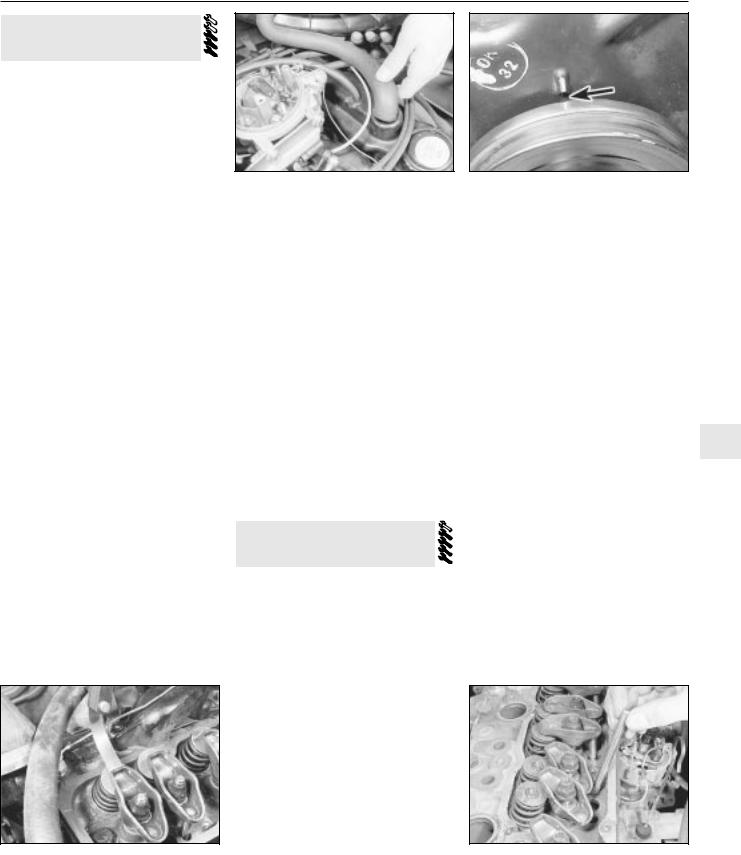
OHV engine 2A•5
7 Valve clearances - adjustment
1This adjustment should be carried out with the engine at its normal operating temperature. If it is being done after overhaul when the engine is cold, repeat the adjustment after the car has been driven a few kilometres when the engine will then be hot.
2Begin by removing the air cleaner, as described in Chapter 4A.
3Mark the spark plug leads to ensure correct refitting and then pull them off the spark plugs.
4Disconnect the engine breather hoses at the rocker cover (see illustration).
5Undo the four bolts securing the rocker cover to the cylinder head and lift off the shaped spreader washers.
6Withdraw the rocker cover from the cylinder head. If it is stuck give it a tap with the palm of your hand to free it.
7Turn the engine by means of the crankshaft pulley bolt, or by engaging top gear and pulling the car forward, until No 1 piston is approaching TDC on the firing stroke. This can be checked by removing No 1 spark plug and feeling for compression with your fingers as the engine is turned, or by removing the distributor cap and checking the position of the rotor arm which should be pointing to the No 1 spark plug lead segment in the cap. The ignition timing marks on the pulley and timing cover must be aligned (see illustration).
8With the engine in this position the following valves can be adjusted - counting from the timing cover end of the engine.
1 exhaust
2 inlet
3 inlet
5 exhaust
9Now turn the engine crankshaft through one complete revolution and adjust the following remaining valves:
4 exhaust
6 inlet
7 inlet
8 exhaust
10As each clearance is being checked, slide a feeler blade of the appropriate size, as given in the Specifications, between the end of the
7.10 Checking a valve clearance
7.4 Removing the breather hose from the rocker cover
valve stem and the rocker arm (see illustration). Adjust the clearance by turning the rocker arm retaining nut using a socket or ring spanner until the blade is a stiff sliding fit.
11It is also possible to check and adjust the clearances with the engine running. This is done in the same way, but each valve is checked in turn. It will of course be necessary to refit the plug leads and No 1 spark plug if this method is adopted. To reduce oil splash place a piece of cardboard, suitably cut to shape, between the pushrod side of the rocker arms and the edge of the cylinder head.
12After adjustment remove all traces of old gasket from the cylinder head mating face and renew the rocker cover gasket if it is cracked or perished.
13Refit the rocker cover and secure with the retaining bolts and shaped spreader washers.
14Refit the spark plug and plug leads, reconnect the engine breather hoses and refit the air cleaner, as described in Chapters 1 and 4.
8 Cylinder head - removal and refitting
Removal
1Make sure that the engine is cold before commencing operations to avoid any chance of the head distorting.
2Disconnect the battery negative terminal
3Drain the cooling system, as described in Chapter 1, and remove the air cleaner, as described in Chapter 4A.
4From behind the engine, undo the two bolts securing the exhaust front pipe to the manifold. Remove the bolts and tension springs; then separate the pipe joint from the manifold.
5Slacken the retaining clip and disconnect the radiator top hose from the thermostat housing in the water pump.
6Slacken the alternator mounting and adjustment arm bolts, move the alternator towards the engine and slip the drivebelt off the pulleys.
7Slacken the retaining clips and disconnect the heater hose and radiator bottom hose from the water pump.
7.7 Ignition timing marks (arrowed) in alignment
8 Disconnect the other heater hose at the cylinder head outlet after slackening the retaining clip.
9 Undo the union nut and disconnect the brake servo vacuum hose from the inlet manifold.
10Note the location of the plug leads to aid refitting and pull them off the spark plugs. Disconnect the HT lead at the coil, undo the distributor cap retaining screws and remove the cap and leads.
11Refer to Chapter 4A and disconnect the choke and accelerator cables from the carburettor. Detach the distributor vacuum advance pipe.
12Disconnect the fuel hose from the carburettor and plug its end after removal.
13Disconnect the engine breather hoses
from the rocker cover. |
2A |
14Undo the three socket-headed screws securing the inlet manifold to the cylinder head. Note the spark plug lead support brackets fitted to the two end retaining bolts.
15Lift the inlet manifold complete with carburettor from the cylinder head and recover the gasket.
16Undo the four bolts and shaped spreader washers and lift off the rocker cover.
17Slacken the rocker arm retaining nuts, move the rocker arms to one side and lift out the pushrods (see illustration). Keep the pushrods in order after removal.
18Undo the cylinder head retaining bolts, half a turn at a time in the reverse sequence to that shown in illustration 8.26. Unscrew the bolts fully and remove them. Obtain new bolts for use when refitting.
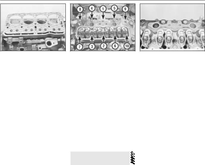
2A•6 OHV engine
8.24 Fitting a cylinder head gasket
19Lift the cylinder head from the block. If it is stuck, tap it free with a soft-faced mallet. Do not insert a lever into the gasket joint - you may damage the mating surfaces.
20With the cylinder head removed, recover the gasket.
21If the cylinder head has been removed for decarbonising or for attention to the valves or springs, reference should be made to Sections 9 and 10.
Refitting
22Before refitting the cylinder head, ensure that the cylinder block and head mating faces are spotlessly clean and dry with all traces of old gasket removed. Use a scraper and wire brush to do this, but take care to cover the water passages and other openings with masking tape or rag to prevent dirt and carbon falling in. Remove all traces of oil and water from the bolt holes, otherwise hydraulic pressure created by the bolts being screwed in could crack the block or give inaccurate torque settings. Ensure that the bolt threads are clean and dry.
23When all is clean, screw two guide studs into the cylinder block. These can be made from the two old cylinder head bolts by cutting off their heads and sawing a screwdriver slot in their ends.
24Locate a new gasket in position on the block as shown (see illustration). Do not use any jointing compound on the gasket
25Lower the cylinder head carefully into position. Screw in new bolts finger tight, remove the guide pins and screw in the two remaining bolts.
26Tighten the cylinder head bolts in the order shown (see illustration) to the first stage specified torque. Now tighten the bolts through three further stages as given in the Specifications. No further retightening will be required.
27Refit the pushrods, making quite sure that each one is located in its tappet.
28Reposition the rocker arms over the ends of the pushrods and then adjust the valve clearances, as described in Section 7.
29Place a new gasket in position and refit the inlet manifold and carburettor (see illustration).
30Refit the rocker cover, using a new
8.26 Cylinder head bolt tightening sequence
gasket, and secure with the four bolts and spreader washers.
31Refit the heater hoses and radiator hoses to the outlets on the water pump and cylinder head.
32Refit the fuel hose to the carburettor, the vacuum advance pipe to the distributor and the breather hoses to the rocker cover.
33Refit and adjust the accelerator and choke cables, as described in Chapter 4A.
34Refit the brake servo vacuum hose to the inlet manifold.
35Refit the distributor cap and reconnect the plug leads and coil lead.
36Slip the drivebelt over the pulleys and adjust its tension, as described in Chapter 1.
37Reconnect the exhaust front pipe to the manifold and tighten the bolts to compress the tension springs.
38Refill the cooling system as described in Chapter 1, refit the air cleaner as described in Chapter 4A and connect the battery negative terminal.
9 Cylinder head - overhaul
1 Unscrew the rocker arm retaining /adjustment nuts and withdraw the rocker arms from the studs. Keep them in order as they are removed.
2To remove the valves, the springs will have to be compressed to allow the split collets to be released from the groove in the upper section of the valve stems. A valve spring compressor will therefore be necessary.
3Locate the compressor to enable the forked end of the arm to be positioned over the valve spring collar whilst the screw part of the clamp is situated squarely on the face of the valve.
4Screw up the clamp to compress the spring and release the pressure of the collar acting on the collets. If the collar sticks, support the head and clamp frame and give the end of the clamp a light tap with a hammer to help release it.
5Extract the two collets and then release the tension of the clamp. Remove the clamp, withdraw the collar and spring and extract the valve. Remove the valve stem seals and the exhaust valve rotators.
8.29 Inlet manifold gasket in position
6 As they are released and removed, keep the valves in order so that if they are to be refitted they will be replaced in their original positions in the cylinder head. A piece of stiff card with eight holes punched in it is a sure method of keeping the valves in order.
7Examine the head of the valves for pitting and burning, especially the heads of the exhaust valves. The valve seating should be examined at the same time. If the pitting on valve and seat is very slight, the marks can be removed by grinding the seats and valves together with coarse, and then fine, valve grinding paste.
8Where bad pitting has occurred to the valve seats it will be necessary to recut them and fit new valves. The latter job should be entrusted to the local agent or engineering works. In practice it is very seldom that the seats are so badly worn. Normally it is the valve that is too badly worn for refitting, and the owner can easily purchase a new set of valves and match them to the seats by valve grinding.
9Valve grinding is carried out as follows. Smear a trace of coarse carborundum paste on the seat face and apply a suction grinder tool to the valve head. With a semi-rotary motion, grind the valve head to its seat, lifting the valve occasionally to redistribute the grinding paste. When a dull matt even surface is produced on both the valve seat and the valve, wipe off the paste and repeat the process with fine carborundum paste, lifting and turning the valve to redistribute the paste as before. A light spring placed under the valve head will greatly ease this operation. When a smooth unbroken ring of light grey matt finish is produced, on both valve and valve seat faces, the grinding operation is complete.
10Scrape away all carbon from the valve head and the valve stem. Carefully clean away every trace of grinding compound; take great care to leave none in the ports or in the valve guides. Clean the valves and valve seats with a paraffin-soaked rag, then with a clean rag and finally, if an air line is available, blow the valves, valve guides and valve ports clean.
11Check that all valve springs are intact. If any one is broken, all should be renewed. Check the free height of the springs against new ones. If some springs are not within
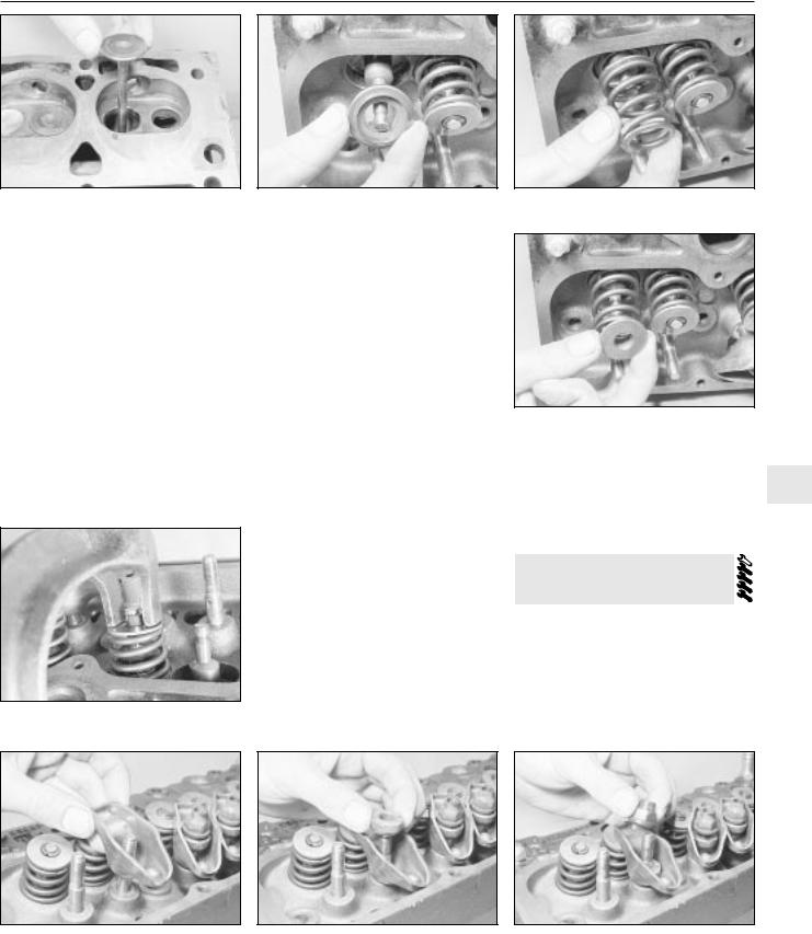
OHV engine 2A•7
9.15 Fitting a valve to its guide
specification, replace them all. Springs suffer from fatigue and it is a good idea to renew them even if they look serviceable.
12Check that the oil supply holes in the rocker arm studs are clear.
13The cylinder head can be checked for warping either by placing it on a piece of plate glass or using a straight-edge and feeler blades. Slight distortion may be corrected by having the head machined to remove metal from the mating face.
14Valve guide renewal is necessary if the valve stem clearance in the guide exceeds that specified. Renewal, or reaming to accept oversize valves, should be left to a GM dealer.
15Commence reassembly by lubricating a valve stem and inserting it into its guide (see illustration).
16Fit the valve stem oil seal, using the protective sleeve supplied with the new seals over the valve stem to avoid damage.
9.20 Compress the spring and fit the collets
9.17 Fitting an exhaust valve rotator
Lubricate the sleeve and push on the seal, ring downwards. Recover the sleeve.
17On exhaust valves, fit the valve rotator
(see illustration).
18Fit the valve spring and collar, with the recessed part of the collar inside the spring
(see illustrations).
19Place the end of the spring compressor over the collar and valve stem and, with the screw head of the compressor over the valve head, screw up the clamp until the spring is compressed past the groove in the valve stem. Then put a little grease round the groove.
20Place the two halves of the split collar (collets) into the groove with the narrow ends pointing towards the spring (see illustration). The grease will hold them in the groove.
21Release the clamp slowly and carefully, making sure that the collets are not dislodged from the groove. When the clamp is fully released the top edges of the collets should be in line with each other. Give the top of each spring a smart tap with a soft-faced mallet when assembly is complete to ensure that the collets are properly settled.
22Repeat the above procedure for the other
7valves.
23The rocker gear can be refitted with the head either on or off the engine. The only part of the procedure to watch is that the rocker nuts must not be screwed down too far or it will not be possible to refit the pushrods.
24Next put the rocker arm over the stud followed by the pivot ball (see illustrations). Make sure that the spring fits snugly round the rocker arm centre section and that the two
9.18a Fit the valve spring . . .
9.18b . . . followed by the spring collar
bearing surfaces of the interior of the arm and the ball face, are clean and lubricated with
engine oil. 2A 25 Oil the stud thread and fit the nut with the self-locking collar uppermost (see illustration). Screw it down until the locking
collar is on the stud.
10 Cylinder head and pistons
- decarbonising
1 This can be carried out with the engine either in or out of the car. With the cylinder head removed, carefully use a wire brush and blunt scraper to clean all traces of carbon deposits from the combustion spaces and the ports. The valve head stems and valve guides should also be freed from any carbon deposits. Wash the combustion spaces and ports down with petrol and scrape the cylinder head surface free of any foreign
9.24a Fitting a rocker arm . . . |
9.24b . . . |
and its pivot ball |
9.25 Fit the nut with the self-locking collar |
|
|
|
uppermost |
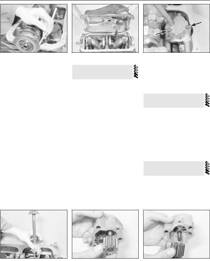
2A•8 OHV engine
11.7 Insert the cork strips in the main bearing cap grooves
matter with the side of a steel rule or a similar article.
2If the engine is installed in the car, clean the pistons and the top of the cylinder bores. If the pistons are still in the block, then it is essential that great care is taken to ensure that no carbon gets into the cylinder bores as this could scratch the cylinder walls or cause damage to the piston and rings. To ensure this does not happen, first turn the crankshaft so that two of the pistons are at the top of their bores. Stuff rag into the other two bores or seal them off with paper and masking tape. The waterways should also be covered with small pieces of masking tape to prevent particles of carbon entering the cooling system and damaging the water pump.
3Press a little grease into the gap between the cylinder walls and the two pistons which are to be worked on. With a blunt scraper carefully scrape away the carbon from the piston crown, taking great care not to scratch the aluminium. Also scrape away the carbon from the surrounding lip of the cylinder wall. When all carbon has been removed, scrape away the grease which will now be contaminated with carbon particles, taking care not to press any into the bores. To assist prevention of carbon build-up the piston crown can be polished with a metal polish. Remove the rags or masking tape from the other two cylinders and turn the crankshaft so that the two pistons which were at the bottom are now at the top. Place rag or masking tape in the cylinders which have been decarbonised and proceed as just described. Decarbonising is now complete.
11.9 Refitting the sump
11 Sump - removal and refitting
Removal
1Jack up the front of the car and securely support it on axle stands (see “Jacking and Vehicle Support”).
2Drain the engine oil into a suitable container (Section 2) and refit the plug after draining.
3Undo the bolts securing the flywheel cover plate and side support braces and remove the cover.
4Undo the retaining bolts and lift away the sump. It will probably be necessary to tap the sump from side to side with a hide or plastic mallet to release the joint face.
Refitting
5Thoroughly clean the sump in paraffin or a suitable solvent and remove all traces of external dirt and internal sludge. Scrape away all traces of old gasket from the sump and crankcase faces and ensure that they are clean and dry. Also clean the bearing cap grooves.
6Apply a thick bead of jointing compound to the crankcase flange and at the joints of the front and rear main bearing caps
7Position the cork side gaskets on the crankcase flanges and then insert the cork and sealing strips to the main bearing cap grooves (see illustration).
8Apply a further bead of jointing compound to the gasket faces and to the gasket joints at the bearing caps.
12.2a Undo the two socket-headed bolts (arrowed) . . .
9Refit the sump (see illustration) and secure it in place with the retaining bolts which should be progressively tightened in a diagonal sequence.
10Refit the flywheel cover plate, lower the car and fill the engine with oil as described in Chapter 1.
12 Oil pump - removal and refitting
Removal
1Remove the sump. as described in Section
2Undo the two socket-headed bolts and withdraw the pump from the crankcase (see illustrations).
Refitting
3 Refitting the pump is the reverse sequence to removal, but engage the pump shaft in the distributor driveshaft slot, and tighten the retaining bolts to the specified torque.
13 Oil pump - overhaul
1 Remove the oil pump, as described in Section 12.
2Undo the two pump cover bolts and lift off the cover and oil pick-up tube. Remove the cover gasket.
3Take out the driving gear and driven gear
(see illustrations).
12.2b . . . |
and remove the oil pump |
13.3a Removing the oil pump driving |
13.3b . . . |
and the driven gear |
|
|
gear . . . |
|
|
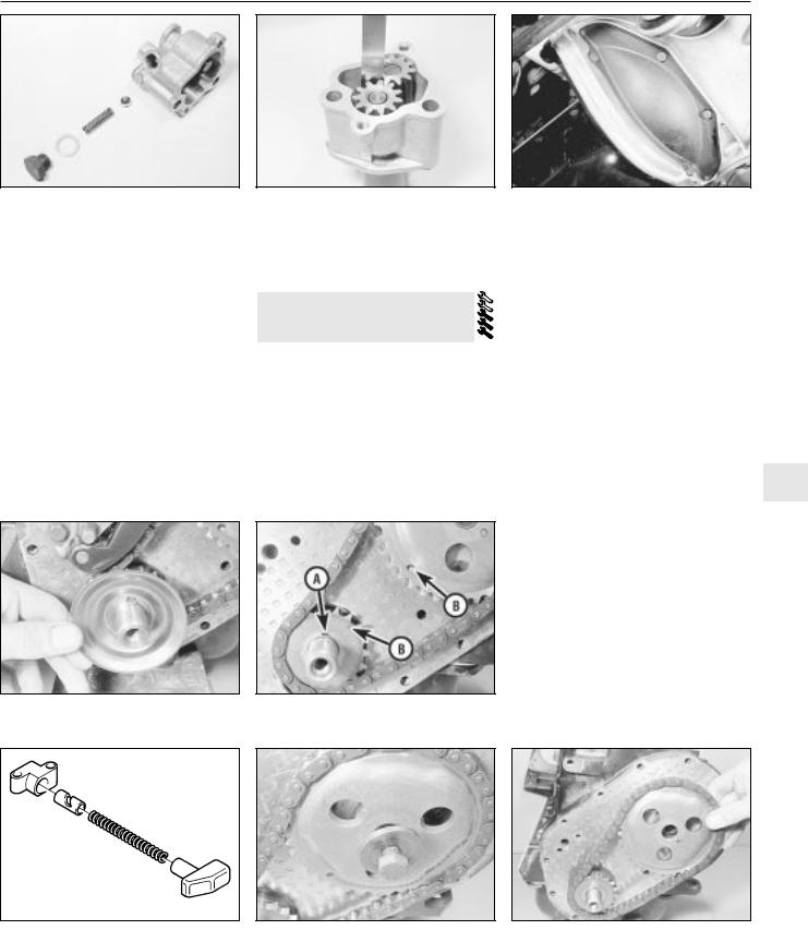
OHV engine 2A•9
13.4 Oil pump and pressure relief valve components
4 Undo the large nut on the side of the housing and remove the sealing washer and oil pressure relief spring and ball valve (see illustration).
5Clean all the parts in paraffin and dry with a lint-free cloth.
6Inspect the pump gears, housing, cover and relief valve ball for scoring, scuff marks or other signs of wear and renew the pump if these signs are evident.
7If the pump condition is satisfactory, check the pump clearances as follows.
8Using a feeler blade, check the backlash between the gear teeth. Place a straight-edge across the top edge of the gears and check their projection. If any of the clearances exceeds the tolerances given in the Specifications, renew the pump (see illustration).
9If the clearances are satisfactory, refit the
14.7 Crankshaft oil slinger
13.8 Check the pump gear teeth backlash
relief valve assembly and assemble the pump gears. Fill the pump with oil and refit the cover using a new gasket. Tighten the cover securing bolts and refit the pump.
14 Timing gear components - removal and refitting
Removal
1 For greater access remove the front right-hand wheel trim and slacken the wheel bolts. Jack up the front of the car, support it securely on axle stands (see “Jacking and Vehicle Support”) and remove the roadwheel.
2Undo the four retaining bolts and remove the clutch access plate at the base of the bellhousing (see illustration).
3Slacken the alternator mounting and adjustment arm bolts, move the alternators
14.8 Crankshaft sprocket keyway (A) and sprocket timing marks (B)
14.2 Clutch access plate
towards the engine and slip the drivebelt off the pulleys.
4Lock the flywheel by wedging a screwdriver between the ring gear teeth and the side of the bellhousing.
5Using a socket or spanner undo the crankshaft pulley retaining bolt and withdraw the pulley.
6Undo the bolts securing the timing cover to the front of the engine and lift off the cover.
7Withdraw the oil slinger from the crankshaft, noting which way round it is fitted
(see illustration).
8Temporarily refit the pulley and turn the crankshaft until the crankshaft sprocket keyway is uppermost and the timing marks on the two sprockets are in alignment (see illustration). Remove the pulley.
9 Undo the two retaining bolts and remove 2A the timing chain tensioner. One of two types
of tensioner may be fitted: simple spring-operated, or oil pressure assisted. With the oil pressure assisted type, restrain the thrust pad to prevent premature ejection of the tensioner components (see illustration).
10Undo the camshaft sprocket retaining bolt and remove the bolt and washer (see illustration). Place a screwdriver through one of the sprocket holes and in contact with the camshaft retaining plate behind the sprocket to stop it turning as the bolt is undone.
11Withdraw the camshaft sprocket and crankshaft sprocket from their respective locations, using a screwdriver as a lever if necessary, then remove the sprockets complete with chain (see illustration).
12Thoroughly clean all the components in
14.9 Timing chain tensioner - oil pressure assisted type
14.10 Camshaft sprocket retaining bolt and washer
14.11 Removing the sprockets and timing chain
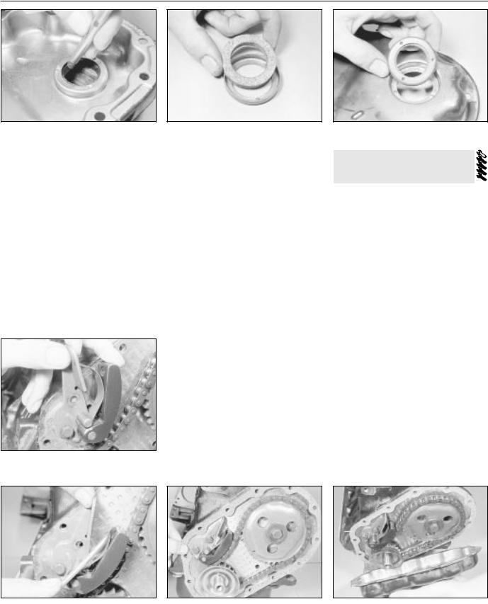
2A•10 OHV engine
14.13 Using a drift to remove the timing cover oil seal
paraffin and dry them with a lint-free cloth. Remove all traces of old gasket from the faces of the timing cover and engine.
Refitting
13To renew the oil seal in the timing cover, place the cover outer face downwards over two blocks of wood and drive out the old seal and holder using a hammer and drift (see illustration).
14Place the new seal (which must have been soaked in engine oil for 24 hours) in the holder and then tap the holder into the cover using a block of wood (see illustrations). The seal holder must be fitted flush with the outer edge of the timing cover.
15Commence reassembly by engaging the chain around the crankshaft sprocket.
16Engage the camshaft sprocket within the loop of the chain so that it can be fitted to the
14.19a Fit the tensioner lower bolt . . .
14.14a Fit the new seal to the holder
camshaft and will have its timing mark in alignment with the one on the crankshaft sprocket. Adjust the camshaft sprocket as necessary within the chain loop to achieve this.
17Fit the sprocket to the camshaft, screw in the bolt and washer and tighten the bolt while holding the sprocket with a screwdriver, as was done during removal.
18Refit the timing chain tensioner. With the oil pressure assisted type, compress the thrust pad by hand, secure the tensioner and release the thrust pad.
19To refit the spring-operated chain tensioner, place the tensioner in position and fit the lower retaining bolt finger tight. Move the spring blade away from the tensioner body with a screwdriver, pivot the tensioner into position and fit the upper retaining bolt, then release the springs and tighten both bolts (see illustrations).
20Position the oil slinger over the crankshaft and place a new gasket on the front of the engine (see illustration). Apply jointing compound to both sides of the gasket.
21Refit the cover and the retaining bolts, but only screw the bolts in two or three turns (see illustration). Position the crankshaft pulley on the crankshaft to centralise the cover and then tighten the bolts progressively in a diagonal sequence.
22Refit the pulley retaining bolt and tighten to the specified torque.
23Refit the drivebelt and adjust its tension, as described in Chapter 1.
24Refit the roadwheel and lower the car to the ground. Tighten the wheel bolts.
14.14b . . . and refit the holder and seal to the timing cover
15 Pistons and connecting rods
- removal and refitting
Removal
1Remove the cylinder head, the sump and the oil pump, as described in earlier Sections.
2The connecting rod big-end caps and rods may not be marked numerically for location when new and therefore they must be inspected for identification marks before dismantling. If no marks are evident, punch, scribe or file identification marks on the caps and rods starting with No 1 at the timing cover end. Mark them all on the same side to avoid confusion during reassembly. If they have already been marked then this will not, of course, be necessary.
3Undo and remove the big-end cap retaining bolts and keep them in order for correct refitting.
4Detach the big-end bearing caps. If stuck, lightly tap them free using a soft-faced mallet.
5To remove the bearing shells for inspection and/or renewal, press the bearing end opposite the groove in both connecting rod and bearing cap and the shells will slide out. Again keep the shells in order of removal.
6The piston rod assemblies are removed through the top of each cylinder bore, being pushed upwards from underneath using a wooden hammer handle which is pushed against the connecting rod. Rotate the crankshaft accordingly to gain suitable access to each rod assembly. Note that, if there is a pronounced wear ridge at the top of the
14.19b . . . then push back the spring, |
14.20 Fitting a new timing cover gasket |
14.21 Refitting the timing cover |
pivot the tensioner and fit the upper bolt |
|
|
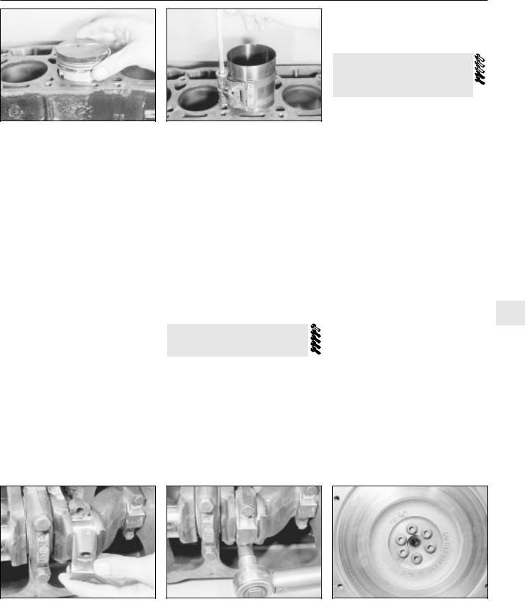
OHV engine 2A•11
15.11 Offering the piston to the bore
cylinder bore, there is a risk of piston ring damage unless the ridge is first removed using a ridge reaming tool, or scraper.
7The pistons should not be separated from their connecting rods unless they or the gudgeon pins are to be renewed. The gudgeon pin is a press fit and special tools are required for removing and installation. This task should therefore be entrusted to your local agent or automotive machine shop.
8If for any reason the pistons are separated from their rods, mark them numerically on the same side as the rod markings to ensure correct refitting.
Refitting
9 If new pistons or piston rings are being fitted to the old bores, it is essential to roughen the cylinder bore walls slightly with medium grit emery cloth to allow the rings to bed in. Do this with a circular up-and-down action to produce a criss-cross pattern on the cylinder bore walls. Make sure that the bearing journal on the crankshaft is protected with masking tape during this operation. Thoroughly clean the bores with a paraffin-soaked rag and dry with a lint-free cloth Remove the tape from the crankshaft journals and clean them also.
10Commence reassembly by lubricating the cylinder bores and crankshaft journals.
11Space the piston rings around the pistons so that their end gaps are 180º apart. In the case of the oil scraper ring, offset the gaps in the upper and lower rails by 25 to 50 mm to right and left of the end gap of the central section. Offer a piston/connecting rod
15.12 Piston ring compressor fitted
assembly to its bore, making sure that it is the right way round (see illustration).
12Oil the piston and rings, then fit a piston ring compressor to the piston and tighten it to compress the rings (see illustration).
13Gently tap the piston through the ring compressor and into its bore using the hammer handle. Guide the connecting rod near to its crankshaft journal and then fit the bearing shell upper half.
14Ease the connecting rod onto the journal, fit the lower shell to the cap and fit the cap to the rod (see illustration). Refit and tighten the retaining bolts to the specified torque (see illustration).
15Repeat the sequence described for the remaining three piston/ connecting rods.
16Refit the cylinder head, oil pump and sump, as described in earlier Sections.
16 Flywheel - removal and refitting
Removal
1 Remove the clutch assembly and the release bearing, as described in Chapter 6.
2 Undo the three bolts and remove the release bearing guide tube.
3Mark the position of the flywheel in relation to the crankshaft mounting flange or pulley.
4Wedge a screwdriver between the ring gear teeth and transmission casing and then undo the socket-headed retaining bolts using a multi-tooth key or socket bit (see illustration). Remove the bolts and withdraw the flywheel.
Refitting
5 Refitting is the reverse sequence to removal. Tighten the flywheel retaining bolts to the specified torque.
17 Engine/transmission mountings - removal and refitting
Removal
1 The engine/transmission assembly is supported in a triangular arrangement of three mountings: one on the right-hand side supporting the engine, one on the left-hand side supporting the transmission and a third centrally sited mount supporting the complete assembly at the rear.
2 To remove either of the front mountings position a jack under the engine or transmission adjacent to the mounting and just take the weight of the engine or transmission.
3 Undo the bolts securing the support bracket to the engine or gearbox and the bolts securing the mounting to the bodyframe. Lift off the bracket and remove the relevant mounting.
4To remove the rear mounting jack up the front of the car and support it on axle stands (see “Jacking and Vehicle Support”).
5Support the engine/transmission assembly
under the differential cover plate using a jack 2A and interposed block of wood.
6 Undo the two bolts securing the mounting to the underbody and the through-bolt and nut securing the mounting to the support bracket. Slide the mounting rearwards out of the bracket and remove it from under the car.
Refitting
7In all cases refitting is the reverse sequence to removal, but tighten the retaining bolts to the specified torque. Where thread locking compound was evident on the old bolts, clean out the bolt holes using a tap (or an old bolt with a slot cut in its threads); clean the bolt threads and apply thread locking compound.
8If there is an arrow stamped on the rear mounting, it should point to the front when the mounting is fitted.
15.14a Fitting a big-end bearing cap |
15.14b Tightening a big-end bearing cap |
|
bolt |
16.4 Flywheel retaining bolts are socket-headed
Loading...