

Page 1
OPEL ASTRA
Owner's Manual
Page 2

Page 3

Contents
Introduction .................................... 2
In brief ............................................ 6
Keys, doors and windows ............ 22
Seats, restraints ........................... 39
Storage ........................................ 63
Instruments and controls ........... 102
Lighting ...................................... 144
Climate control ........................... 157
Driving and operating ................. 167
Vehicle care ............................... 230
Service and maintenance .......... 291
Technical data ........................... 294
Customer information ................ 328
Index .......................................... 338
Page 4
2 Introduction
Introduction
Page 5

Introduction 3
Vehicle specific data
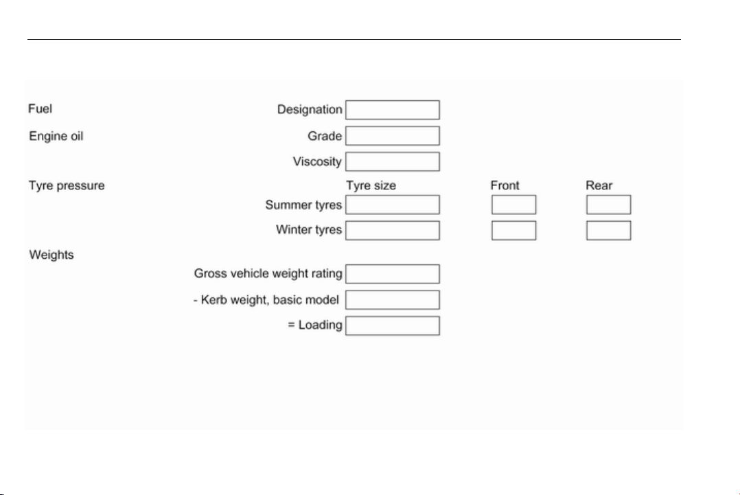
Please enter your vehicle's data on
the previous page to keep it easily
accessible. This information is
available in the sections "Service and
maintenance" and "Technical data"
as well as on the identification plate.
Introduction
Your vehicle is a designed
combination of advanced technology,
safety, environmental friendliness
and economy.
This Owner's Manual provides you
with all the necessary information to
enable you to drive your vehicle
safely and efficiently.
Make sure your passengers are
aware of the possible risk of accident
and injury which may result from
improper use of the vehicle.
You must always comply with the
specific laws and regulations of the
country that you are in. These laws
may differ from the information in this
Owner's Manual.
Disregarding the description given in
this manual may affect your warranty.
When this Owner's Manual refers to a
workshop visit, we recommend your
Opel Service Partner. For gas
vehicles we recommend an Opel
Repairer authorised for servicing gas
vehicles.
All Opel Service Partners provide
first-class service at reasonable
prices. Experienced mechanics
trained by Opel work according to
specific Opel instructions.
The customer literature pack should
always be kept ready to hand in the
vehicle.
Using this manual
● This manual describes all options
and features available for this
model. Certain descriptions,
including those for display and
menu functions, may not apply to
your vehicle due to model
variant, country specifications,
special equipment or
accessories.
● The "In brief" section will give you
an initial overview.
● The table of contents at the
beginning of this manual and
within each section shows where
the information is located.
● The index will enable you to
search for specific information.
● This Owner's Manual depicts lefthand drive vehicles. Operation is
similar for right-hand drive
vehicles.
● The Owner's Manual uses the
engine identifier code. The
corresponding sales designation
and engineering code can be
found in the section "Technical
data".
● Directional data, e.g. left or right,
or front or back, always relate to
the direction of travel.
● Displays may not support your
specific language.
● Display messages and interior
labelling are written in bold
letters.
Page 6
4 Introduction
Danger, Warnings and
Cautions
9 Danger
Text marked 9 Danger provides
information on risk of fatal injury.
Disregarding this information may
endanger life.
9 Warning
Text marked 9 Warning provides
information on risk of accident or
injury. Disregarding this
information may lead to injury.
Caution
Text marked Caution provides
information on possible damage to
the vehicle. Disregarding this
information may lead to vehicle
damage.
Symbols
Page references are indicated with 3.
3 means "see page".
Page references and index entries
refer to the indented headings given
in the section table of content.
We wish you many hours of
pleasurable driving.
Adam Opel AG
Page 7

Introduction 5
Page 8
6 In brief
In brief
Initial drive information
Vehicle unlocking
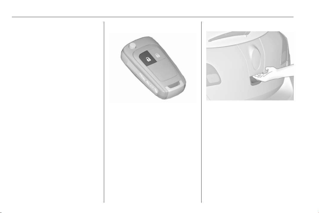
c to unlock the doors and load
Press
compartment. Open the doors by
pulling the handles.
5-door hatchback, Sports tourer
To open the tailgate, push the
touchpad switch below the brand
emblem.
Page 9

In brief 7
3-door hatchback
To open the tailgate, push the brand
emblem at the bottom half.
Press x on remote control to unlock
and open the tailgate. The doors
remain locked.
4-door notchback
Press x on the remote control for at
least two seconds; the boot lid opens
slightly.
Radio remote control 3 23, Central
locking system 3 24, Load
compartment 3 27.
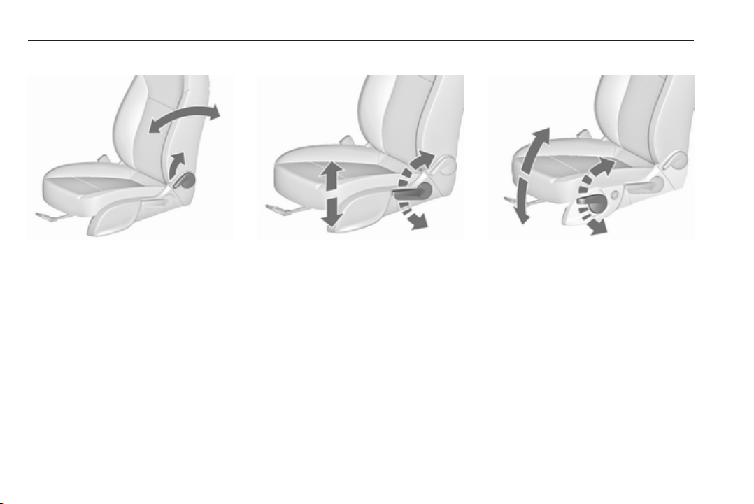
Seat adjustment
Longitudinal adjustment
Pull handle, slide seat, release
handle. Try to move the seat back and
forth to ensure that the seat is locked
in place.
Seat position 3 41, Manual seat
adjustment 3 42, Power seat
adjustment 3 48.
Page 10
8 In brief
Backrest inclination
Pull lever, adjust inclination and
release lever. Allow the seat to
engage audibly.
Seat position 3 41, Manual seat
adjustment 3 44, Power seat
adjustment 3 48, Seat folding
3 47.
Seat height
Lever pumping motion
up : seat higher
down : seat lower
Seat position 3 41, Manual seat
adjustment 3 44, Power seat
adjustment 3 48.
Seat inclination
Lever pumping motion
up : front end higher
down : front end lower
Seat position 3 41, Manual seat
adjustment 3 44, Power seat
adjustment 3 48.
Page 11
In brief 9
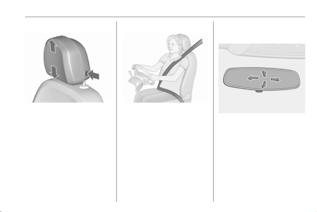
Head restraint adjustment
Press release button, adjust height,
engage.
Head restraints 3 39.
Seat belt
Pull out the seat belt and engage in
belt buckle. The seat belt must not be
twisted and must fit close against the
body. The backrest must not be tilted
back too far (maximum approx. 25 °).
To release belt, press red button on
belt buckle.
Seat position 3 41, Seat belts
3 51, Airbag system 3 54.
Mirror adjustment
Interior mirror
To adjust the mirror, move the mirror
housing in the desired direction.
Manual anti-dazzle interior mirror
3 33, Automatic anti-dazzle interior
mirror 3 33.
Page 12
10 In brief
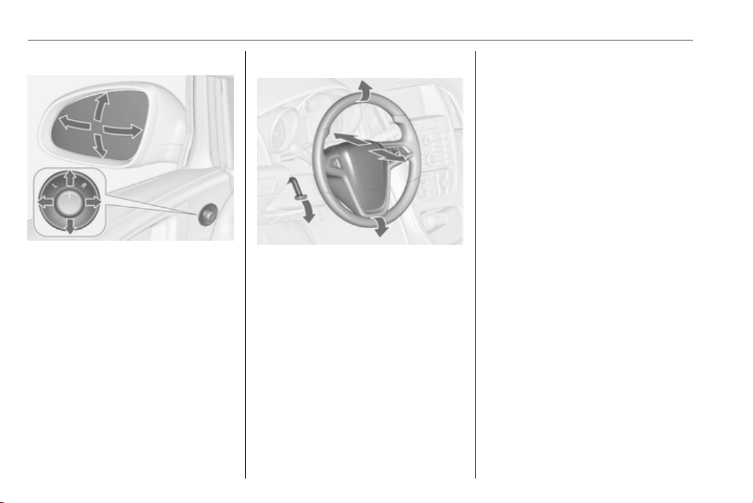
Exterior mirrors
Select the relevant exterior mirror and
adjust it.
Convex exterior mirrors 3 32,
Electric adjustment 3 32, Folding
exterior mirrors 3 32, Heated
exterior mirrors 3 33.
Steering wheel adjustment
Unlock the lever, adjust the steering
wheel, then engage the lever and
ensure it is fully locked.
Do not adjust the steering wheel
unless the vehicle is stationary and
the steering wheel lock has been
released.
Airbag system 3 54, Ignition
positions 3 169.
Page 13
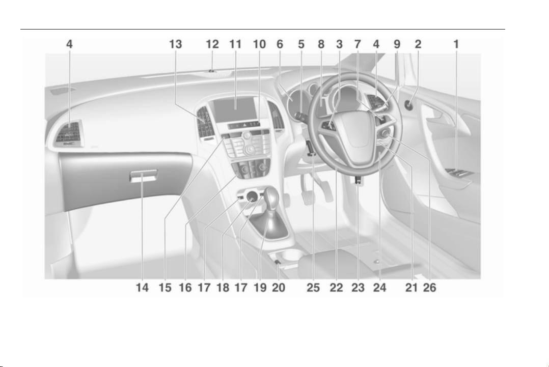
Instrument panel overview
In brief 11
Page 14

12 In brief
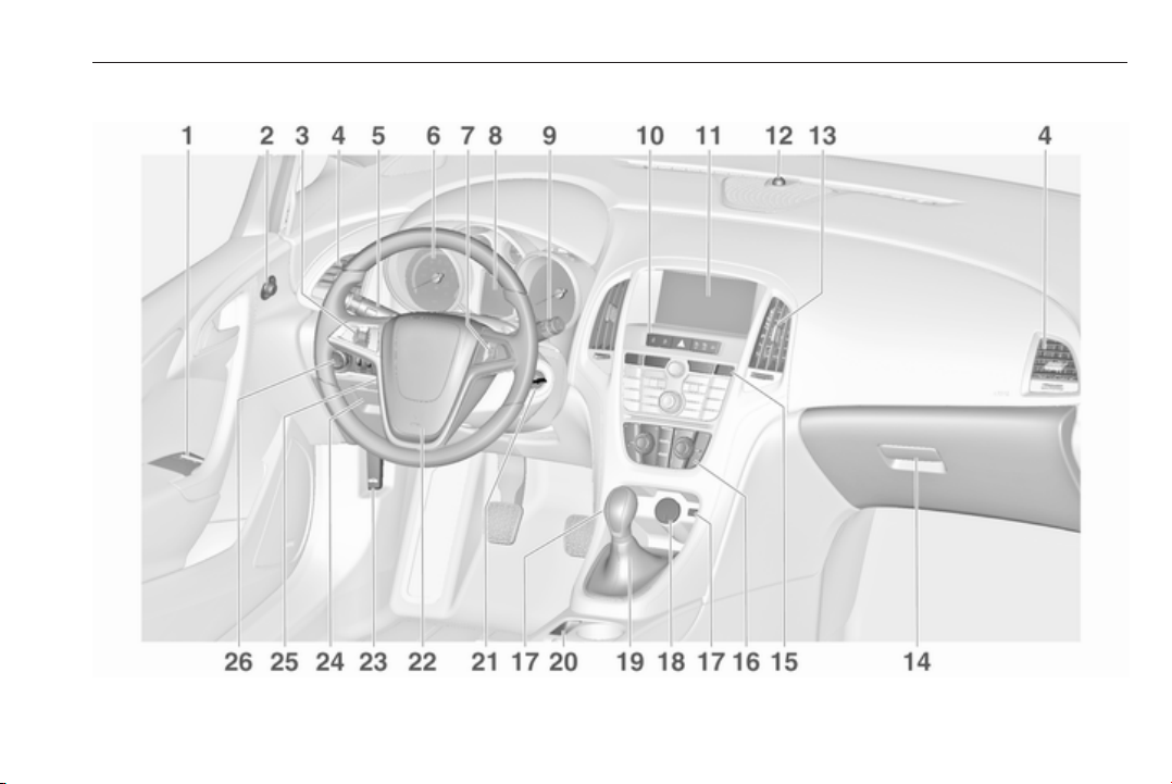
1 Power windows ..................... 34
2 Exterior mirrors ..................... 32
3 Cruise control ..................... 187
Speed limiter ....................... 189
Adaptive cruise control .......190
Forward collision alert ......... 197
4 Side air vents ...................... 165
5 Turn and lane-change
signals, headlight flash,
low beam and high beam,
high beam assist ................. 151
Exit lighting ......................... 155
Parking lights ...................... 152
Buttons for Driver
Information Centre .............. 122
6 Instruments ........................ 110
7 Steering wheel controls .....103
8 Driver Information Centre .... 122
9 Windscreen wiper,
windscreen washer
system, headlight washer
system, rear window
wiper, rear window washer
system ................................. 104
10 Sport mode ........................ 184
Central locking system .......... 24
Fuel selector ....................... 111
Hazard warning flashers ....151
Control indicator for airbag
deactivation ........................ 116
Control indicator for front
passenger seat belt ........... 116
Tour mode .......................... 184
11 Info-Display ........................ 126
12 Anti-theft alarm system
status LED ........................... 29
13 Centre air vents .................. 165
14 Glovebox .............................. 63
15 Traction Control system
(TC) ..................................... 182
Electronic Stability Control
(ESC) .................................. 183
Parking assist systems .......203
Lane departure warning ..... 217
Eco button for stop-start
system ................................. 170
Unlock button for boot lid ......27
16 Climate control system ........ 157
17 AUX input, USB input, SD
card slot ................................ 11
18 Power outlet ........................ 108
19 Selector lever, manual
transmission ....................... 179
Automatic transmission ...... 175
20 Electric parking brake ......... 180
21 Ignition switch with
steering wheel lock ............ 169
22 Horn ................................... 104
Driver airbag ........................ 54
23 Bonnet release lever .......... 232
24 Storage compartment,
fuse box ............................. 260
25 Steering wheel adjustment 103
26 Light switch ........................ 144
Headlight range
adjustment ......................... 147
Front fog lights ................... 152
Page 15

Rear fog light ...................... 152
Instrument illumination ....... 153
In brief 13
Page 16
14 In brief
Page 17
In brief 15
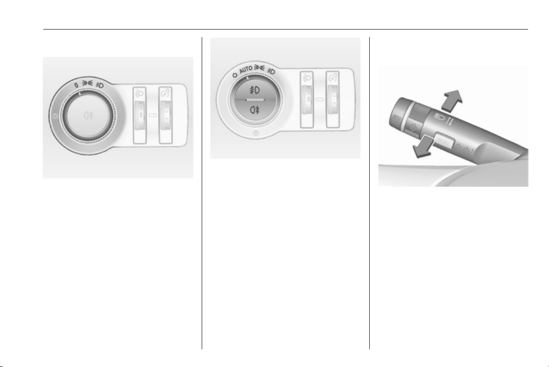
Exterior lighting
Turn light switch:
: lights off
7
: sidelights
8
: low beam
9
Automatic light control
AUTO : automatic light control:
exterior lighting is switched
m
8
9
Fog lights
Press light switch:
>
r
Lighting 3 144.
on and off automatically
: activation or deactivation of
the automatic light control
: sidelights
: low beam
: front fog lights
: rear fog light
Headlight flash, high beam and low beam
headlight flash : pull lever
high beam : push lever
low beam : push or pull lever
Automatic light control 3 145, High
beam 3 146, Headlight flash 3 146,
Adaptive forward lighting 3 148.
Page 18
16 In brief
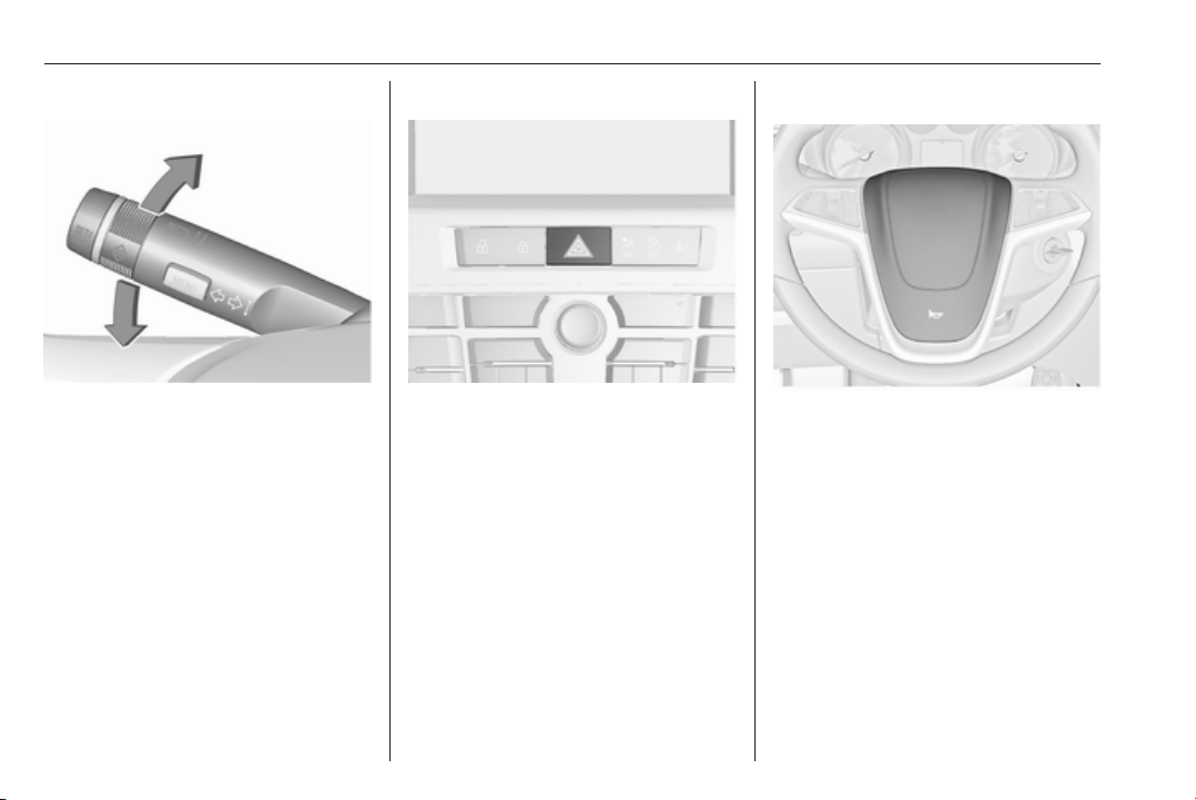
Turn and lane-change signals
lever up : right turn signal
lever down : left turn signal
Turn and lane-change signals
3 151, Parking lights 3 152.
Hazard warning flashers
Operated by pressing ¨.
Hazard warning flashers 3 151.
Horn
Press j.
Page 19
In brief 17
Climate control
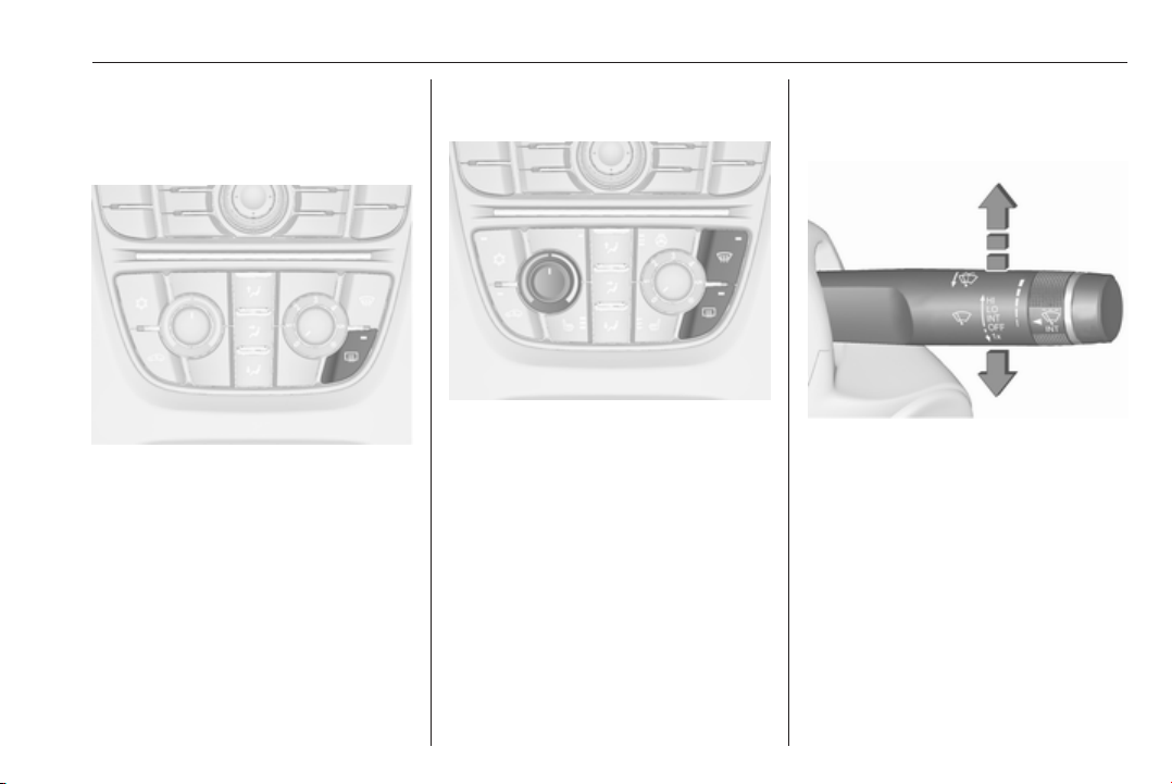
Heated rear window, heated exterior mirrors
The heating is operated by pressing
Ü.
Heated rear window 3 36.
Demisting and defrosting the windows
Press V.
Set the temperature control to the
highest level.
Heated rear window Ü on.
Climate control system 3 157.
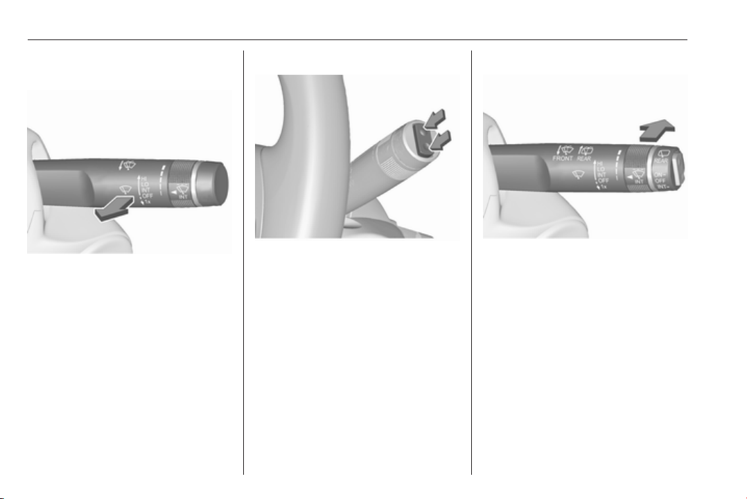
Washer and wiper systems
Windscreen wiper
HI : fast
LO : slow
INT : interval wiping or automatic
wiping with rain sensor
OFF : off
For a single wipe when the
windscreen wiper is off, press the
lever down to position 1x.
Windscreen wiper 3 104, Wiper
blade replacement 3 238.
Page 20
18 In brief
Windscreen and headlight washer
Pull lever.
Windscreen and headlight washer
system 3 104, Washer fluid 3 235.
Rear window wiper
Press the rocker switch to activate the
rear window wiper:
upper switch : continuous
operation
lower switch : intermittent
operation
middle position : off
Rear window washer
Push lever.
Washer fluid is sprayed on the rear
window and the wiper wipes a few
times.
Rear window wiper/washer 3 106.
Page 21
In brief 19
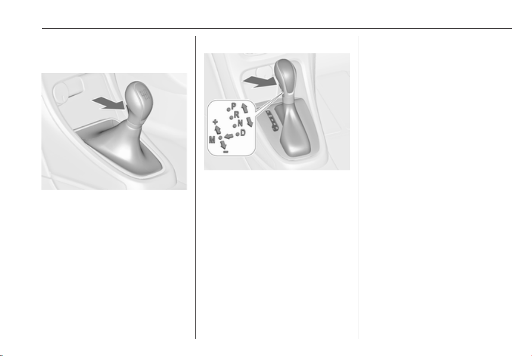
Transmission
Manual transmission
Reverse: with the vehicle stationary,
depress clutch pedal, press the
release button on the selector lever
and engage the gear.
If the gear does not engage, set the
lever to neutral, release the clutch
pedal and depress again; then repeat
gear selection.
Manual transmission 3 179.
Automatic transmission
P : park
R : reverse
N : neutral
D : automatic mode
M : manual mode: move selector
lever from D to the left.
: manual mode upshifting
<
: manual mode downshifting
]
The selector lever can only be moved
out of P when the ignition is on and
the brake pedal is applied. To engage
P or R, press the release button.
Automatic transmission 3 175.
Starting off
Check before starting off
● Tyre pressure and condition
3 266, 3 311.
● Engine oil level and fluid levels
3 233.
● All windows, mirrors, exterior
lighting and number plates are
free from dirt, snow and ice and
are operational.
● Proper position of mirrors, seats,
and seat belts 3 32, 3 41,
3 52.
● Brake function at low speed,
particularly if the brakes are wet.
Page 22
20 In brief
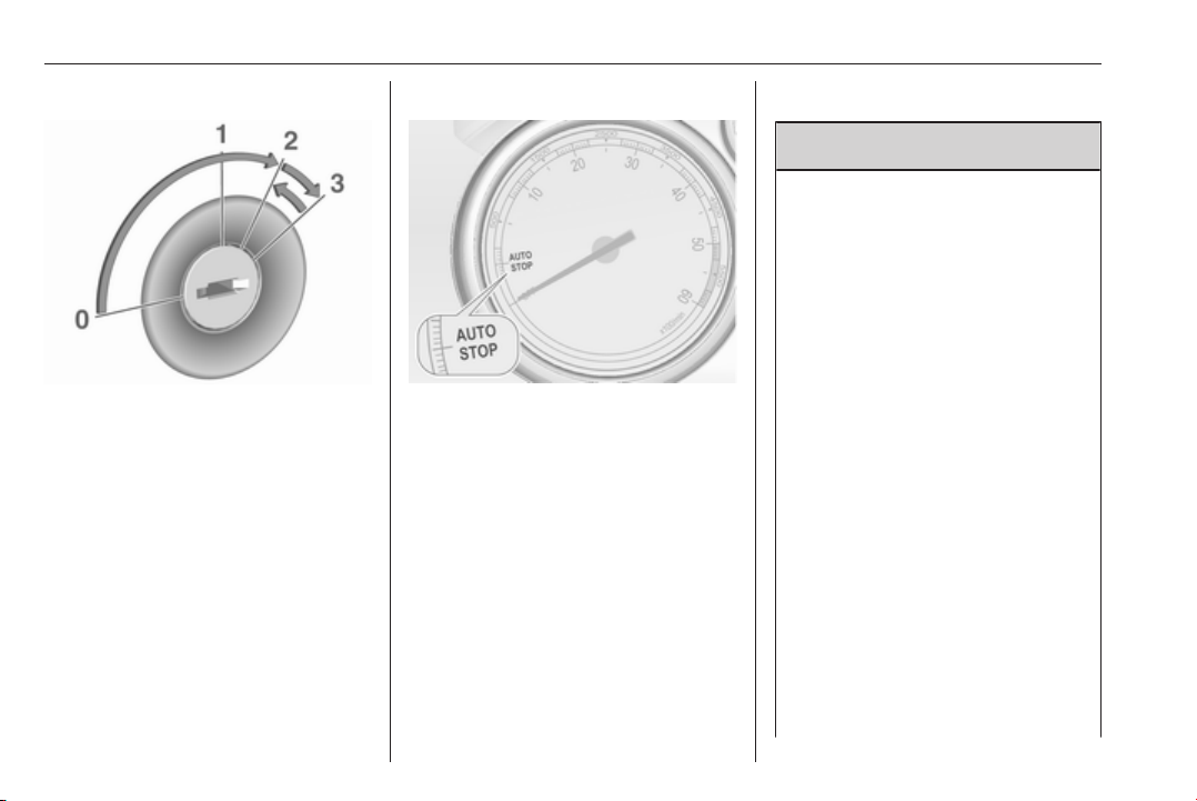
Starting the engine
● Turn key to position 1.
● Move the steering wheel slightly
to release the steering wheel
lock.
● Operate clutch and brake.
● Automatic transmission in P or N.
● Do not operate accelerator pedal.
● Diesel engines: turn the key to
position 2 for preheating and wait
until control indicator !
extinguishes.
● Turn key to position 3 and
release.
Starting the engine 3 169.
Stop-start system
If the vehicle is at a low speed or at a
standstill and certain conditions are
fulfilled, activate an Autostop as
follows:
● Depress the clutch pedal.
● Set the lever in neutral.
● Release the clutch pedal.
An Autostop is indicated by the
needle at the AUTOSTOP position in
the tachometer.
To restart the engine, depress the
clutch pedal again.
Stop-start system 3 170.
Parking
9 Warning
● Do not park the vehicle on an
easily ignitable surface. The
high temperature of the
exhaust system could ignite the
surface.
● Always apply the parking
brake. Activate the manual
parking brake without pressing
the release button. Apply as
firmly as possible on a downhill
slope or uphill slope. Depress
brake pedal at the same time to
reduce operating force.
For vehicles with electric
parking brake, pull switch m for
approx. one second.
The electric parking brake is
applied when control indicator
m illuminates 3 117.
● Switch off the engine.
● If the vehicle is on a level
surface or uphill slope, engage
first gear or set the selector
Page 23

In brief 21
lever to position P before
removing the ignition key. On
an uphill slope, turn the front
wheels away from the kerb.
If the vehicle is on a downhill
slope, engage reverse gear or
set the selector lever to position
P before removing the ignition
key. Turn the front wheels
towards the kerb.
● Close the windows and the
sunroof.
● Remove the ignition key from
the ignition switch. Turn the
steering wheel until the
steering wheel lock is felt to
engage.
For vehicles with automatic
transmission, the key can only
be removed when the selector
lever is in position P.
●
Lock the vehicle by pressing e on
the radio remote control.
Activate the anti-theft alarm
system 3 29.
● The engine cooling fans may run
after the engine has been
switched off 3 232.
Caution
After running at high engine
speeds or with high engine loads,
operate the engine briefly at a low
load or run in neutral for
approx. 30 seconds before
switching off, in order to protect
the turbocharger.
Keys, locks 3 22, Laying the vehicle
up for a long period of time 3 231.
Page 24
22 Keys, doors and windows
Keys, doors and windows
Keys, locks ................................... 22
Keys .......................................... 22
Car Pass .................................... 23
Radio remote control ................. 23
Memorised settings ................... 24
Central locking system .............. 24
Automatic locking ...................... 26
Child locks ................................. 26
Doors ........................................... 27
Load compartment .................... 27
Vehicle security ............................ 29
Anti-theft locking system ........... 29
Anti-theft alarm system .............. 29
Immobiliser ................................ 31
Exterior mirrors ............................ 32
Convex shape ........................... 32
Electric adjustment .................... 32
Folding mirrors .......................... 32
Heated mirrors ........................... 33
Interior mirrors ............................. 33
Manual anti-dazzle .................... 33
Automatic anti-dazzle ................ 33
Windows ...................................... 34
Windscreen ............................... 34
Manual windows ........................ 34
Power windows ......................... 34
Heated rear window .................. 36
Sun visors .................................. 36
Roof ............................................. 37
Sunroof ...................................... 37
Glass panel ............................... 38
Keys, locks
Keys
Caution
Do not attach heavy or bulky items
to the ignition key.
Replacement keys
The key number is specified in the
Car Pass or on a detachable tag.
The key number must be quoted
when ordering replacement keys as it
is a component of the immobiliser
system.
Locks 3 287.
The code number of the adapter for
the locking wheel nuts is specified on
a card. It must be quoted when
ordering a replacement adapter.
Wheel changing 3 275.
Page 25
Keys, doors and windows 23
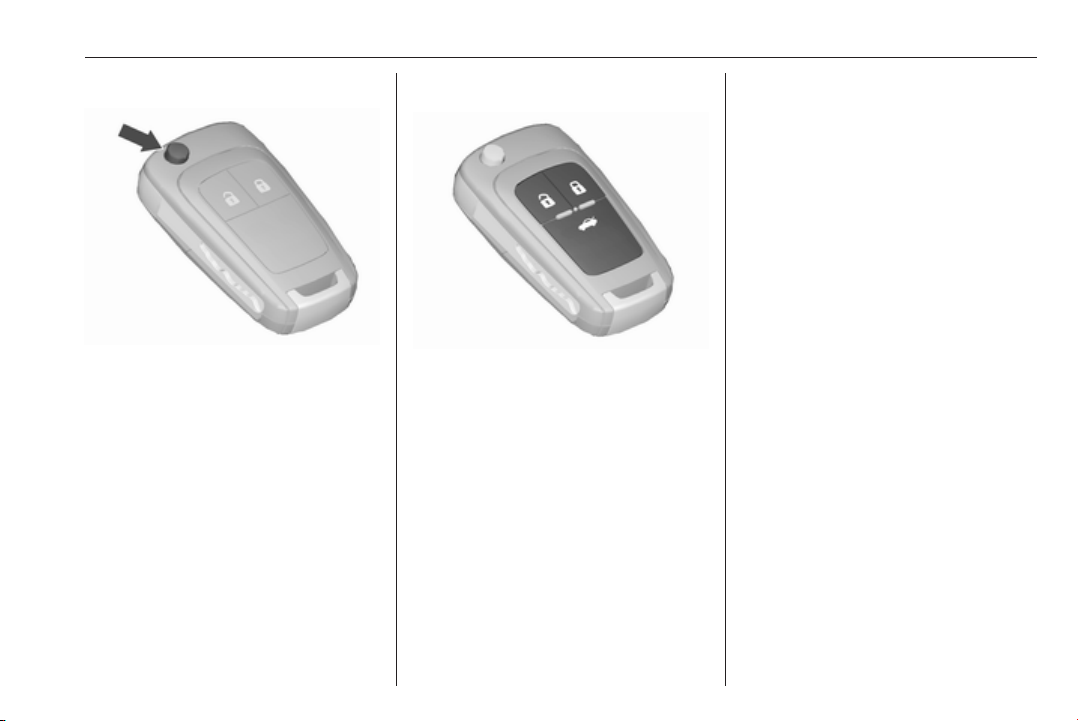
Key with foldaway key section
Press button to extend. To fold the
key, first press the button.
Car Pass
The Car Pass contains security
related vehicle data and should
therefore be kept in a safe place.
When the vehicle is taken to a
workshop, this vehicle data is needed
in order to perform certain operations.
Radio remote control
Used to operate:
● central locking system
● anti-theft locking system
● anti-theft alarm system
● power windows
● sunroof
The radio remote control has a range
of approx. 20 metres. It can be
restricted by external influences. The
hazard warning flashers confirm
operation.
Handle with care, protect from
moisture and high temperatures and
avoid unnecessary operation.
Fault
If the central locking system cannot
be operated with the radio remote
control, it may be due to the following:
● Range is exceeded.
● Battery voltage is too low.
● Frequent, repeated operation of
the radio remote control while not
in range, which will require resynchronisation.
● Overload of the central locking
system by operating at frequent
intervals, the power supply is
interrupted for a short time.
● Interference from higher-power
radio waves from other sources.
Unlocking 3 24.
Basic settings
Some settings can be changed in the
Settings menu in the Info-Display.
Vehicle personalisation 3 134.
Radio remote control battery replacement
Replace the battery as soon as the
range reduces.
Page 26

24 Keys, doors and windows
Batteries do not belong in household
waste. They must be disposed of at
an appropriate recycling collection
point.
Key with foldaway key section
Extend the key and open the unit.
Replace the battery (battery type
CR 2032), paying attention to the
installation position. Close the unit
and synchronise.
Radio remote control synchronisation
After replacing the battery, unlock the
door with the key in the driver's door
lock. The radio remote control is
synchronised by switching on the
ignition.
Memorised settings
Whenever the key is removed from
the ignition switch, the following
settings are automatically memorised
by the key:
● lighting
● Infotainment system
● central locking system
● Sport mode settings
● comfort settings
The saved settings are automatically
used the next time the memorised key
is inserted into the ignition switch and
turned to position 1 3 169.
A precondition is that Personalization
by driver is activated in the personal
settings of the Graphic-Info-Display.
This must be set for each key used.
On vehicles equipped with
Colour-Info-Display, the
personalisation is permanently
activated.
Vehicle personalisation 3 134.
Central locking system
Unlocks and locks doors, load
compartment and fuel filler flap.
A pull on an interior door handle
unlocks the respective door. Pulling
the handle once more opens the door.
Note
In the event of an accident in which
airbags or belt pretensioners are
deployed, the vehicle is
automatically unlocked.
Page 27
Keys, doors and windows 25
Note
A short time after unlocking with the
remote control, the doors are
relocked automatically if no door has
been opened.
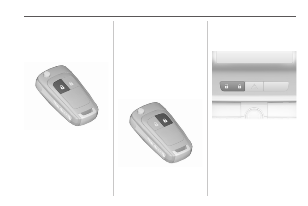
Unlocking
Press c.
Two settings are selectable:
● To unlock only the driver's door,
load compartment and fuel filler
flap, press c once. To unlock all
doors, press c twice.
●
Press c once to unlock all doors,
load compartment and fuel filler
flap.
The setting can be changed in the
Settings menu in the Info-Display.
Vehicle personalisation 3 134.
The setting can be saved for the key
being used. Memorised settings
3 24.
Unlocking and opening the tailgate
3 27.
Locking
Close doors, load compartment and
fuel filler flap.
Press e.
If the driver's door is not closed
properly, the central locking system
will not work.
Central locking buttons
Locks or unlocks all doors, the load
compartment and fuel filler flap from
inside the passenger compartment.
Press e to lock.
Press c to unlock.
Page 28
26 Keys, doors and windows
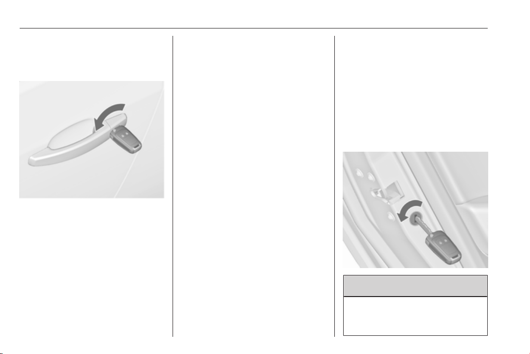
Fault in radio remote control system
Unlocking
Manually unlock the driver's door by
turning the key in the lock. Switch on
the ignition and press the central
locking button c to unlock the other
doors, load compartment and fuel
filler flap. By switching on the ignition,
the anti-theft locking system is
deactivated.
Locking
Manually lock the driver's door by
turning the key in the lock.
Fault in central locking system
Unlocking
Manually unlock the driver's door by
turning the key in the lock. The other
doors can be opened by pulling the
interior handle twice. The load
compartment and fuel filler flap
cannot be opened. To deactivate the
anti-theft locking system, switch on
the ignition 3 29.
Locking
Push inside locking knob of all doors
except driver's door. Then close the
driver's door and lock it from the
outside with the key. The fuel filler flap
and tailgate cannot be locked.
Automatic locking
This security feature can be
configured to automatically lock all
doors, load compartment and fuel
filler flap as soon as a certain speed
is exceeded.
Additionally, it is configurable to
unlock the driver's door or all doors
after the ignition is switched off and
the ignition key is removed (manual
transmission) or the selector lever is
moved to position P (automatic
transmission).
Settings can be changed in the
Settings menu in the Info-Display.
Vehicle personalisation 3 134.
The settings can be saved for the key
being used 3 24.
Child locks
9 Warning
Use the child locks whenever
children are occupying the rear
seats.
Page 29

Keys, doors and windows 27
Using a key or suitable screwdriver,
turn the child lock in the rear door to
the horizontal position. The door
cannot be opened from the inside.
To deactivate, turn the child lock to
the vertical position.
Doors
Load compartment
Tailgate
Opening
5-door hatchback
After unlocking, push the touchpad
switch below the brand emblem and
open the tailgate.
3-door hatchback
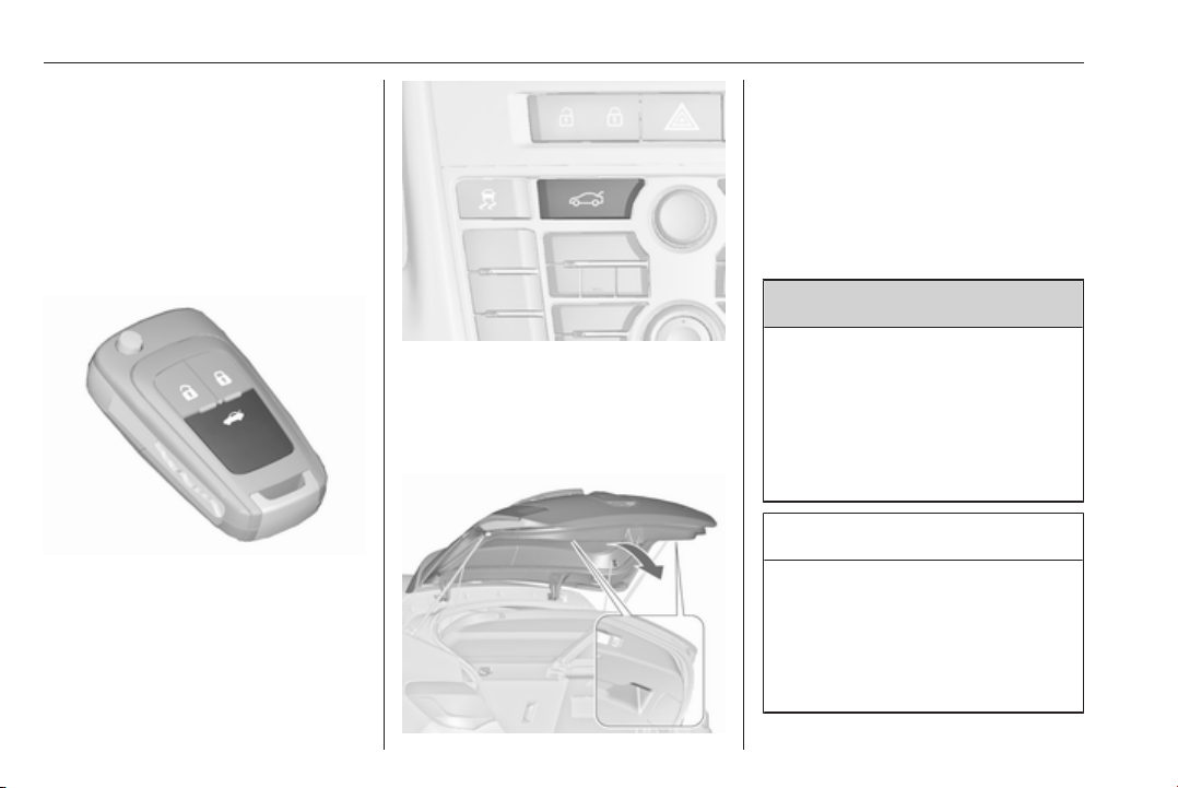
Press x on radio remote control or
push the brand emblem at the bottom
half to unlock and open the tailgate.
Page 30
28 Keys, doors and windows
Pressing x opens the tailgate even
if the doors are locked.
Sports tourer
After unlocking, push the touchpad
switch under the tailgate moulding
and open the tailgate.
Central locking system 3 24.
4-door notchback
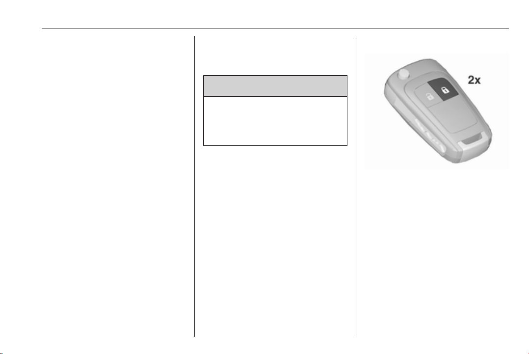
To unlock the boot lid, press x on
the remote control for at least two
seconds, or, to open from the inside,
press x in the centre console; the
boot lid is opened slightly.
With the doors centrally locked, the
boot lid cannot be opened by pressing
x in the centre console.
Closing
Use one of the interior handles.
Do not push the touchpad switch or
the emblem whilst closing as this will
unlock the tailgate again.
Central locking system 3 24.
General hints for operating tailgate
9 Danger
Do not drive with the tailgate open
or ajar, e.g. when transporting
bulky objects, since toxic exhaust
gases, which cannot be seen or
smelled, could enter the vehicle.
This can cause unconsciousness
and even death.
Caution
Before opening the tailgate check
overhead obstructions, such as a
garage door, to avoid damage to
the tailgate. Always check the
moving area above and behind the
tailgate.
Page 31
Keys, doors and windows 29
Note
The installation of certain heavy
accessories onto the tailgate may
affect its ability to remain open.
Vehicle security
Anti-theft locking system
9 Warning
Do not use the system if there are
people in the vehicle! The doors
cannot be unlocked from the
inside.
The system deadlocks all the doors.
All doors must be closed otherwise
the system cannot be activated.
If the ignition was on, the driver's door
must be opened and closed once so
that the vehicle can be secured.
Unlocking the vehicle disables the
mechanical anti-theft locking system.
This is not possible with the central
locking button.
Activating
Press e on the radio remote control
twice within 15 seconds.
Anti-theft alarm system
The anti-theft alarm system is
combined with the anti-theft locking
system.
It monitors:
● doors, tailgate, bonnet
● passenger compartment
including adjoining load
compartment
Page 32
30 Keys, doors and windows
● vehicle inclination, e.g. if it is
raised
● ignition
Activation
● Self-activated 30 seconds after
locking the vehicle by pressing e
once.
●
Directly by pressing e twice
briefly within five seconds.
Note
Changes to the vehicle interior such
as the use of seat covers, and open
windows or sunroof, could impair the
function of passenger compartment
monitoring.
Activation without monitoring of passenger compartment and vehicle inclination
Switch off the monitoring of
passenger compartment and vehicle
inclination when animals are being
left in the vehicle, because of high
volume ultrasonic signals or
movements triggering the alarm. Also
switch off when the vehicle is on a
ferry or train.
1. Close tailgate, bonnet, windows
and sunroof.
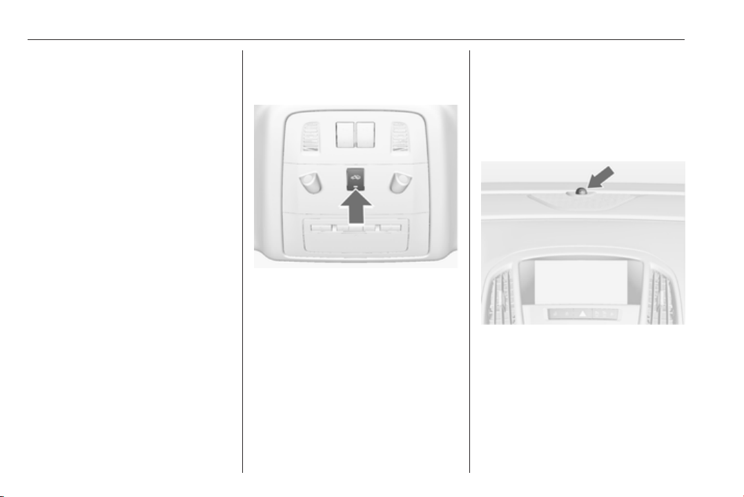
2. Press o. LED in the button o
illuminates for a maximum of ten
minutes.
3. Close doors.
4. Activate the anti-theft alarm
system.
Status message is displayed in the
Driver Information Centre.
Status LED
Status LED is integrated in the sensor
on top of the instrument panel.
Status during the first 30 seconds of
anti-theft alarm system activation:
LED illuminates : test, arming delay
LED flashes
quickly
: doors, tailgate or
bonnet not
completely closed,
or system fault
Page 33

Keys, doors and windows 31
Status after system is armed:
LED flashes
slowly
Seek the assistance of a workshop in
the event of faults.
: system is armed
Deactivation
Unlocking the vehicle by pressing c
deactivates the anti-theft alarm
system.
The system is not deactivated by
unlocking the driver's door with the
key or with the central locking button
in the passenger compartment.
Alarm
When triggered, the alarm horn
sounds and the hazard warning lights
flash simultaneously. The number
and duration of alarm signals are
stipulated by legislation.
The alarm can be silenced by
pressing any button on the radio
remote control or by switching on the
ignition.
The anti-theft alarm system can be
deactivated only by pressing c or by
switching on the ignition.
A triggered alarm, which has not been
interrupted by the driver, will be
indicated by the hazard warning
lights. They will flash quickly three
times the next time the vehicle is
unlocked with the radio remote
control. Additionally, a warning
message or a warning code is
displayed in the Driver Information
Centre after switching on the ignition.
Vehicle messages 3 128.
Immobiliser
The system is part of the ignition
switch and checks whether the
vehicle is allowed to be started with
the key being used.
The immobiliser is activated
automatically after the key has been
removed from the ignition switch.
If the control indicator d flashes when
the ignition is on, there is a fault in the
system; the engine cannot be started.
Switch off the ignition and repeat the
start attempt.
If the control indicator continues
flashing, attempt to start the engine
using the spare key and seek the
assistance of a workshop.
Note
The immobiliser does not lock the
doors. You should always lock the
vehicle after leaving it and switch on
the anti-theft alarm system 3 24,
3 29.
Control indicator d 3 121.
Page 34
32 Keys, doors and windows
Exterior mirrors
Convex shape
The convex exterior mirror contains
an aspherical area and reduces blind
spots. The shape of the mirror makes
objects appear smaller, which will
affect the ability to estimate
distances.
Electric adjustment
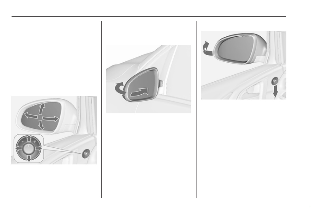
Select the relevant exterior mirror by
turning the control to left (L) or right
(R). Then swivel the control to adjust
the mirror.
In position 0 no mirror is selected.
Folding mirrors
For pedestrian safety, the exterior
mirrors will swing out of their normal
mounting position if they are struck
with sufficient force. Reposition the
mirror by applying slight pressure to
the mirror housing.
Electric folding
Turn control to 0, then push the
control down. Both exterior mirrors
will fold.
Push the control down again - both
exterior mirrors return to their original
position.
If an electrically folded mirror is
manually extended, pressing down
the control will only electrically extend
the other mirror.
Page 35

Keys, doors and windows 33
Heated mirrors
Operated by pressing Ü.
Heating works with the engine
running and is switched off
automatically after a short time.
Interior mirrors
Manual anti-dazzle
To reduce dazzle, adjust the lever on
the underside of the mirror housing.
Automatic anti-dazzle
Dazzle from following vehicles at
night is automatically reduced.
Page 36
34 Keys, doors and windows
Windows
Windscreen
Heat-reflecting windscreen
The heat-reflecting windscreen has a
coating which reflects solar radiation.
Also data signals, e.g. from toll
stations, might be reflected.
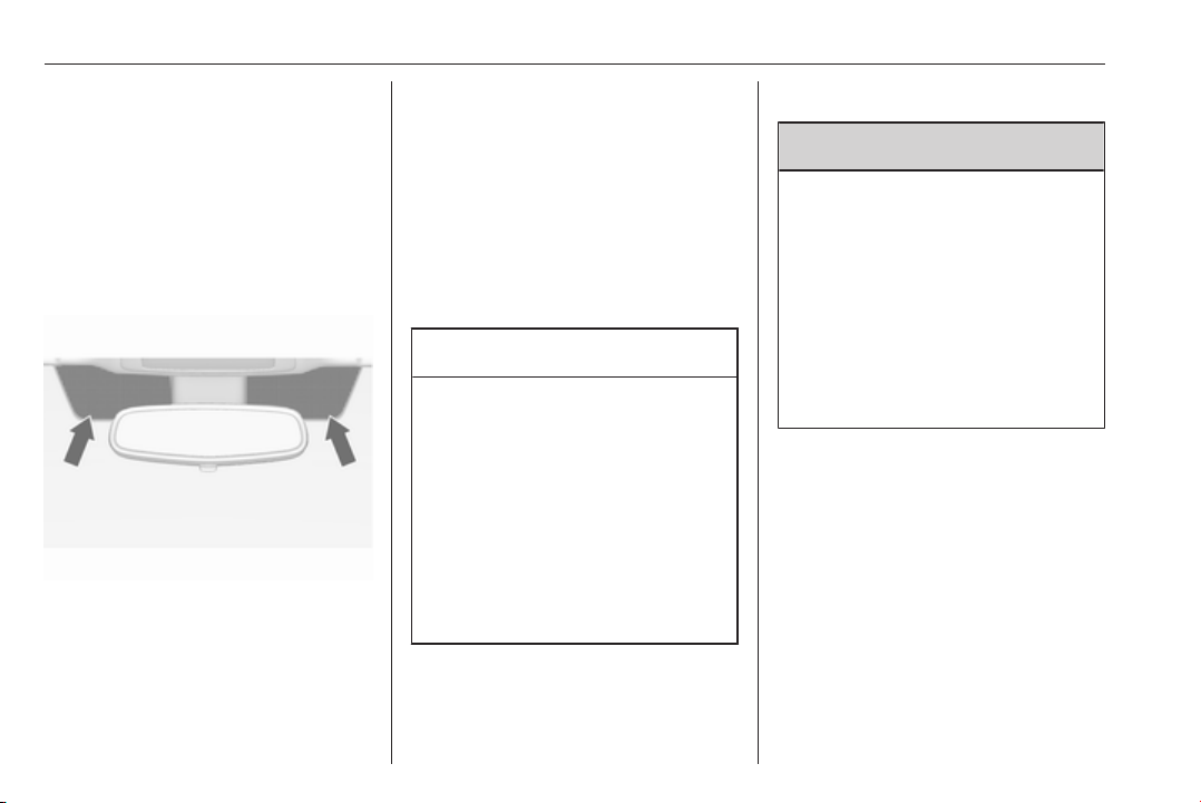
The marked areas on the windscreen
are not covered with the coating.
Devices for electronic data recording
and fee payment must be attached in
these areas. Otherwise data
recording malfunctions may occur.
Windscreen stickers
Do not attach stickers such as toll
road stickers or similar on the
windscreen in the area of the interior
mirror. Otherwise the detection zone
of the sensor and the view area of the
camera in the mirror housing could be
restricted.
Windscreen replacement
Caution
If the vehicle has a front-looking
camera sensor for the driver
assistance systems, it is very
important that any windscreen
replacement is performed
accurately according to Opel
specifications. Otherwise, these
systems may not work properly
and there is a risk of unexpected
behaviour and/or messages from
these systems.
Manual windows
The door windows can be opened or
closed with the window cranks.
Power windows
9 Warning
Take care when operating the
power windows. Risk of injury,
particularly to children.
If there are children on the rear
seats, switch on the child safety
system for the power windows.
Keep a close watch on the
windows when closing them.
Ensure that nothing becomes
trapped in them as they move.
Switch on ignition to operate power
windows. Retained power off 3 169.
Page 37
Keys, doors and windows 35
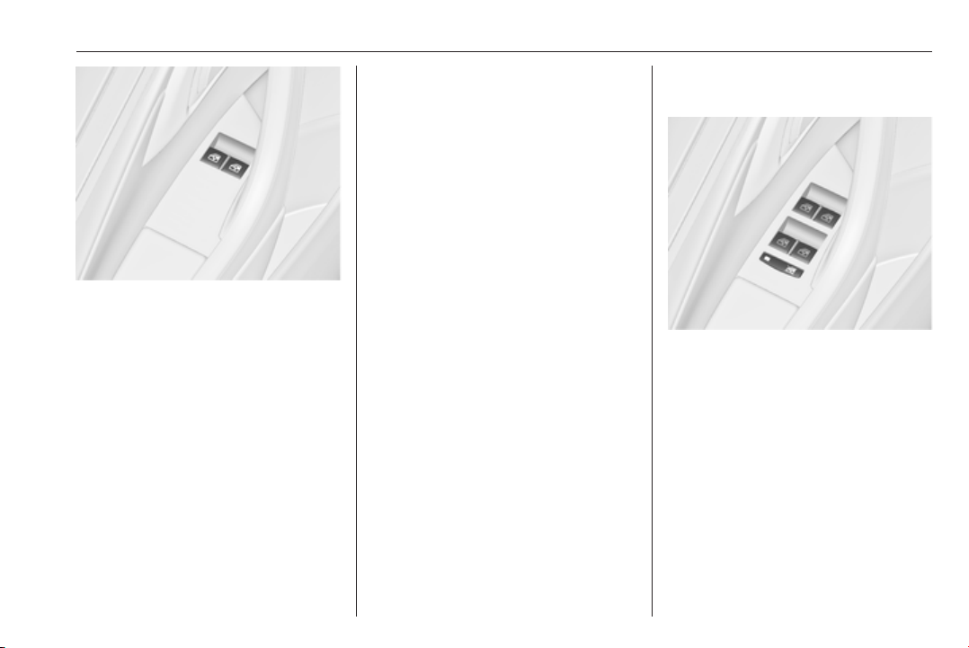
Operate the switch for the respective
window by pushing to open or pulling
to close.
Pushing or pulling gently to the first
detent: window moves up or down as
long as the switch is operated.
Pushing or pulling firmly to the second
detent and then releasing: window
moves up or down automatically with
safety function enabled. To stop
movement, operate the switch once
more in the same direction.
Safety function
If the window glass encounters
resistance above the middle of the
window during automatic closing, it is
immediately stopped and opened
again.
Override safety function
In the event of closing difficulties due
to frost or the like, switch on the
ignition, then pull the switch to the first
detent and hold. The window moves
up without safety function enabled.
To stop movement, release the
switch.
Child safety system for rear windows
Press z to deactivate rear door
power windows; the LED illuminates.
To activate, press z again.
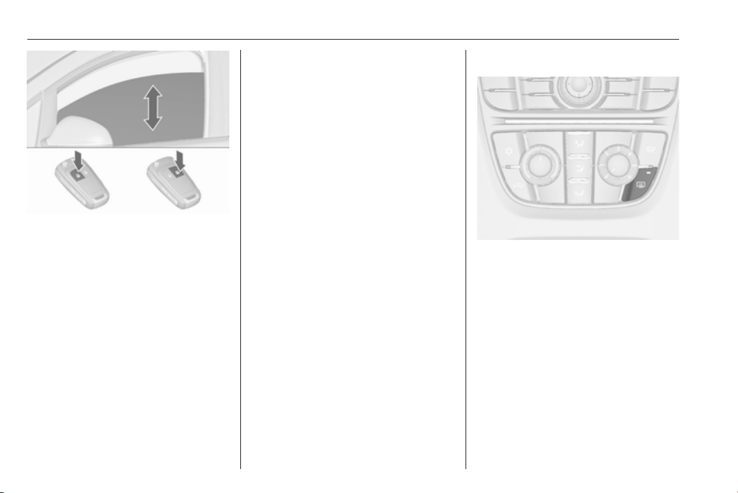
Operating windows from outside
The windows can be operated
remotely from outside the vehicle.
Page 38
36 Keys, doors and windows
Press and hold c to open windows.
Press and hold e to close windows.
Release button to stop window
movement.
If the windows are fully opened or
closed, the hazard warning lights will
flash twice.
Overload
If the windows are repeatedly
operated within short intervals, the
window operation is disabled for
some time.
Initialising the power windows
If the windows cannot be closed
automatically (e.g. after
disconnecting the vehicle battery), a
warning message or a warning code
is displayed in the Driver Information
Centre.
Vehicle messages 3 128.
Activate the window electronics as
follows:
1. Close doors.
2. Switch on ignition.
3. Pull switch until the window is
closed and keep pulling for
additional two seconds.
4. Repeat for each window.
Heated rear window
Operated by pressing Ü.
Heating works with the engine
running and is switched off
automatically after a short time.
Sun visors
The sun visors can be folded down or
swivelled to the side to prevent
dazzling.
If the sun visors have integral mirrors,
the mirror covers should be closed
when driving.
A ticket holder is located on the
backside of the sun visor.
Page 39
Keys, doors and windows 37
Roof
Sunroof
9 Warning
Take care when operating the
sunroof. Risk of injury, particularly
to children.
Keep a close watch on the
movable parts when operating
them. Ensure that nothing
becomes trapped in them as they
move.
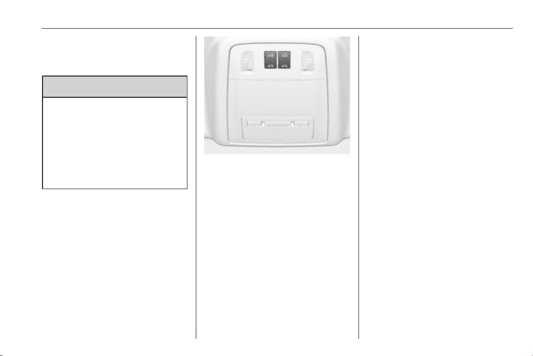
Switch on ignition to operate the
sunroof.
Open or close
Press p or r gently to the first
detent: sunroof is opened or closed
with safety function enabled as long
as the switch is operated.
Press p or r firmly to the second
detent and then release: the sunroof
is opened or closed automatically
with safety function enabled. To stop
movement, operate the switch once
more.
Raise or close
Press q or r: sunroof is raised or
closed automatically with safety
function enabled.
If the sunroof is raised, it can be
opened in one step by pressing p.
Sunblind
The sunblind is manually operated.
Close or open the sunblind by sliding.
When the sunroof is open, the
sunblind is always open.
General hints
Safety function
If the sunroof encounters resistance
during automatic closing, it is
immediately stopped and opened
again.
Override safety function
In the event of closing difficulties,
e.g. due to frost, hold the switch r
pressed to the second detent. The
sunroof closes with safety function
disabled. To stop movement, release
the switch.
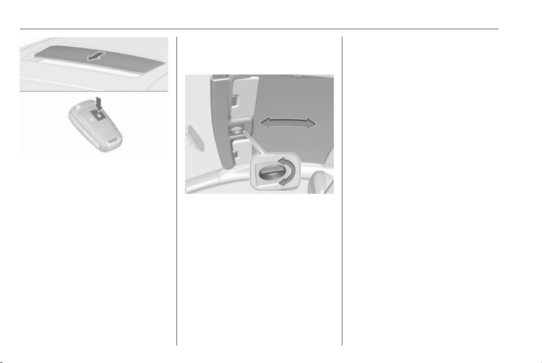
Closing sunroof from outside
The sunroof can be closed remotely
from outside the vehicle.
Page 40
38 Keys, doors and windows
Press and hold e to close the sunroof.
Release the button to stop the
movement.
Initialising after a power failure
After a power failure, it may only be
possible to operate the sunroof to a
limited extent. Have the system
initialised by your workshop.
Glass panel
Panorama roof
Turn the handle and move the roof
cover to a suitable position.
The roof cover engages in position
after releasing the handle.
Note
Close the sun visors before sliding
the roof lining.
Page 41
Seats, restraints 39
Seats, restraints
Head restraints ............................ 39
Active head restraints ................ 40
Front seats ................................... 41
Seat position .............................. 41
Seat adjustment ........................ 42
Manual seat adjustment ............ 44
Seat folding ............................... 47
Power seat adjustment .............. 48
Armrest ...................................... 50
Heating ...................................... 50
Rear seats ................................... 50
Armrest ...................................... 50
Seat belts ..................................... 51
Three-point seat belt ................. 52
Airbag system .............................. 54
Front airbag system ................... 54
Side airbag system .................... 55
Curtain airbag system ............... 56
Airbag deactivation .................... 56
Child restraints ............................. 58
Child restraint systems .............. 58
Child restraint installation
locations ................................... 59
ISOFIX child restraint systems ..62
Top-tether fastening eyes .......... 62
Head restraints
Position
9 Warning
Only drive with the head restraint
set to the proper position.
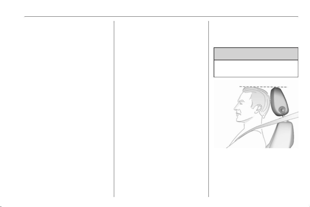
The upper edge of the head restraint
should be at upper head level. If this
is not possible for extremely tall
people, set to highest position, and
set to lowest position for small people.
Page 42
40 Seats, restraints
Adjustment
Head restraints on front seats
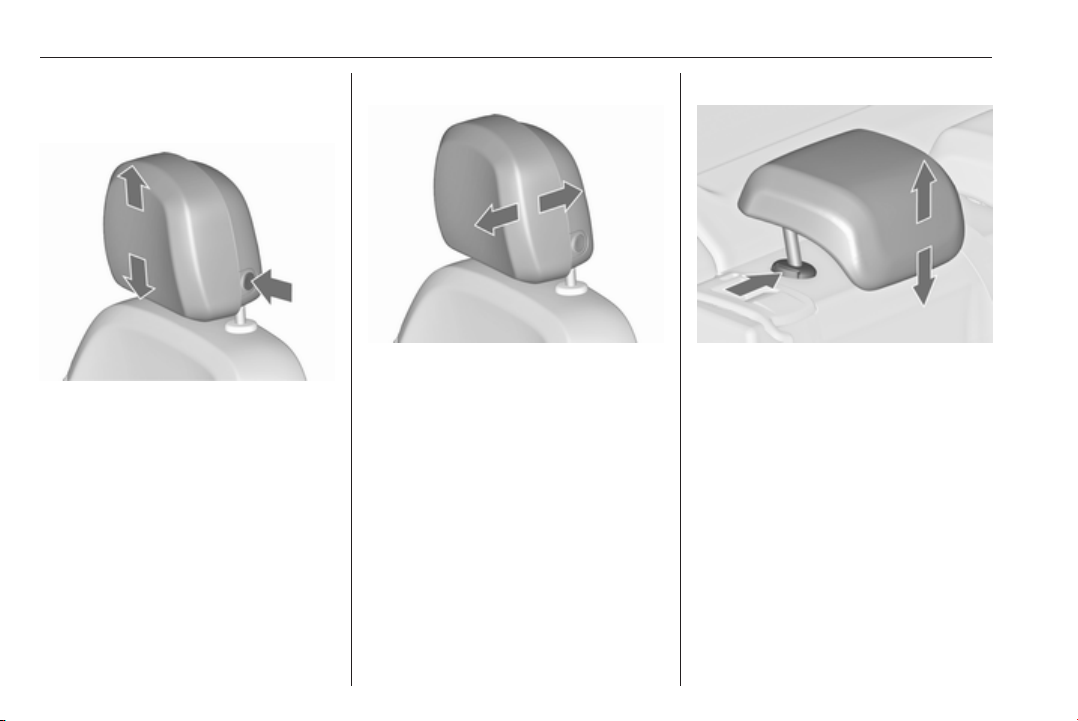
Height adjustment
Press release button, adjust height,
engage.
Horizontal adjustment
To adjust horizontally, pull the head
restraint forwards. It engages in
several positions.
To return to its rearmost position, pull
fully forwards and release.
Head restraints on rear seats
Height adjustment
Pull the head restraint upwards or
press the catch to release and push
the head restraint downwards.
Removal
Press both catches, pull the head
restraint upwards and remove.
Active head restraints
In the event of a rear-end impact, the
front parts of the active head
restraints are moved slightly
Page 43
Seats, restraints 41
forwards. Thus the head is supported
so that the risk of whiplash injury is
reduced.
Note
Approved accessories may only be
attached if the seat is not in use.
Front seats
Seat position
9 Warning
Only drive with the seat correctly
adjusted.
9 Warning
Never adjust seats while driving as
they could move uncontrollably.
9 Danger
Do not sit nearer than 25 cm from
the steering wheel, to permit safe
airbag deployment.
9 Warning
Never store any objects under the
seats.
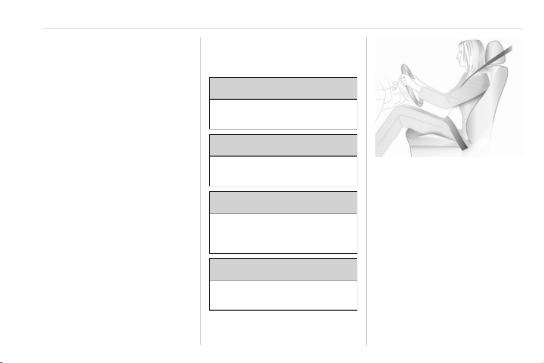
● Sit with buttocks as far back
against the backrest as possible.
Adjust the distance between the
seat and the pedals so that legs
are slightly angled when pressing
the pedals. Slide the front
passenger seat as far back as
possible.
● Set seat height high enough to
have a clear field of vision on all
sides and of all display
instruments. There should be at
least one hand of clearance
between head and the roof
frame. Your thighs should rest
lightly on the seat without
pressing into it.
Page 44
42 Seats, restraints
● Sit with shoulders as far back
against the backrest as possible.
Set the backrest rake so that it is
possible to easily reach the
steering wheel with arms slightly
bent. Maintain contact between
shoulders and the backrest when
turning the steering wheel. Do
not angle the backrest too far
back. We recommend a
maximum rake of approx. 25°.
● Adjust seat and steering wheel in
a way that the wrist rests on top
of the steering wheel while the
arm is fully extended and
shoulders on the backrest.
● Adjust the steering wheel 3 103.
● Adjust the head restraint 3 39.
● Adjust the height of the seat belt
3 52.
● Adjust the thigh support so that
there is a space approx. two
fingers wide between the edge of
the seat and the hollow of the
knee.
● Adjust the lumbar support so that
it supports the natural shape of
the spine.
Seat adjustment
Drive only with engaged seats and
backrests.
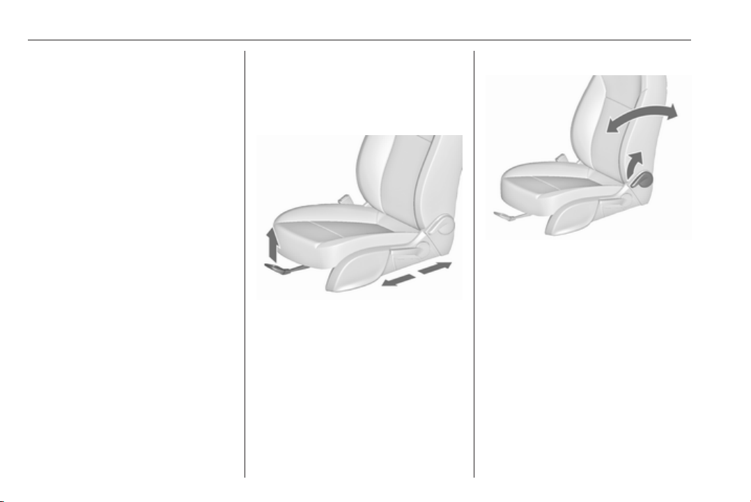
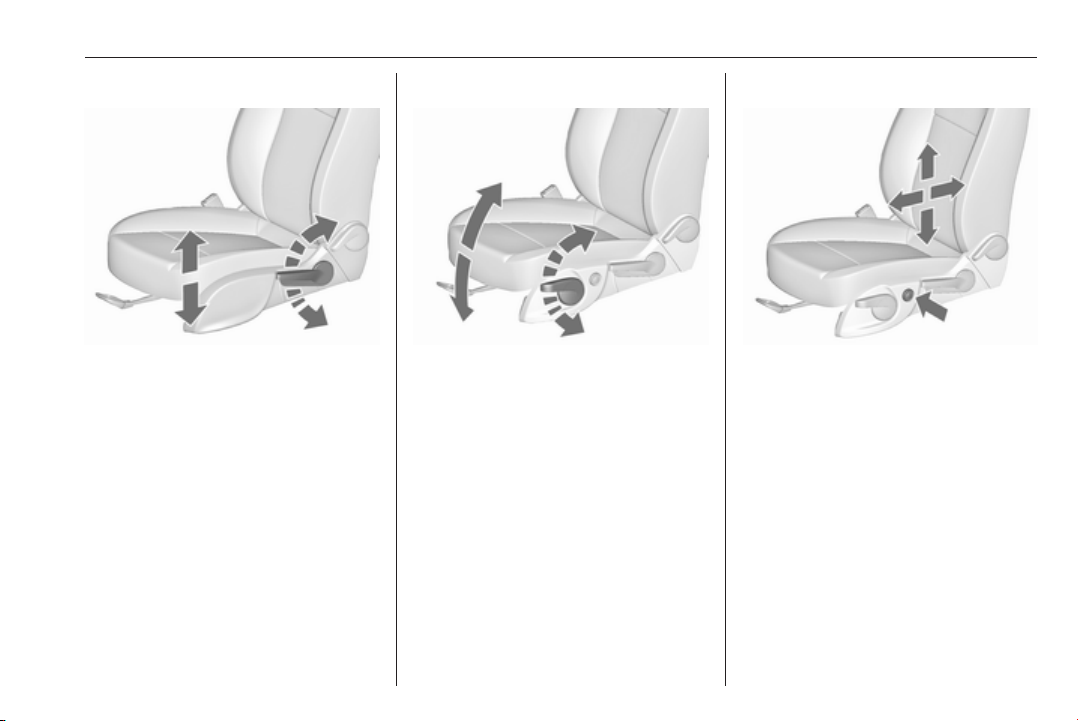
Longitudinal adjustment
Pull handle, slide seat, release
handle. Try to move the seat back and
forth to ensure that the seat is locked
in place.
Backrest inclination
Pull lever, adjust inclination and
release lever. Allow the backrest to
engage audibly.
Page 45
Seats, restraints 43
Seat height
Lever pumping motion
up : seat higher
down : seat lower
Seat inclination
Lever pumping motion
up : front end higher
down : front end lower
Lumbar support
Adjust lumbar support using the fourway switch to suit personal
requirements.
Moving support up and down: push
switch up or down.
Increasing and decreasing support:
push switch forwards or backwards.
Page 46
44 Seats, restraints
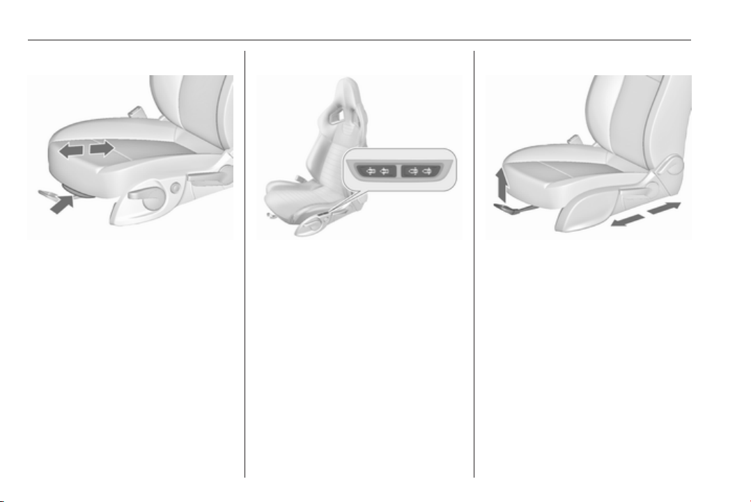
Adjustable thigh support
Pull the lever and slide the thigh
support.
Side bolster, OPC version
Adjust seat width and backrest width
using the switches to suit personal
requirements.
Operate front rocker switch to change
seat width.
Operate rear rocker switch to change
backrest width.
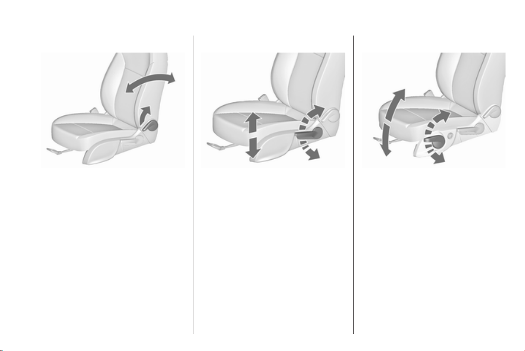
Manual seat adjustment
Drive only with engaged seats and
backrests.
Longitudinal adjustment
Pull handle, slide seat, release
handle. Try to move the seat back and
forth to ensure that the seat is locked
in place.
Page 47
Seats, restraints 45
Backrest inclination
Pull lever, adjust inclination and
release lever. Allow the backrest to
engage audibly.
Seat height
Lever pumping motion
up : seat higher
down : seat lower
Seat inclination
Lever pumping motion
up : front end higher
down : front end lower
Page 48
46 Seats, restraints
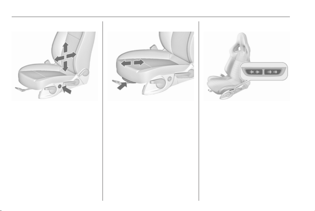
Lumbar support
Adjust lumbar support using the fourway switch to suit personal
requirements.
Moving support up and down: push
switch up or down.
Increasing and decreasing support:
push switch forwards or backwards.
Adjustable thigh support
Pull the lever and slide the thigh
support.
Side bolster, OPC version
Adjust seat width and backrest width
using the switches to suit personal
requirements.
Operate front rocker switch to change
seat width.
Operate rear rocker switch to change
backrest width.
Page 49
Seats, restraints 47
Seat folding
Caution
When seat height is in highest
position, push head restraints
down and lift up sun visors before
folding backrest forwards.
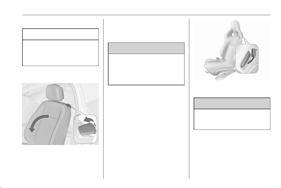
Seat folding on manual operated seats
Lift release lever and fold backrest
forwards, then slide seat forwards to
the stop.
To restore, slide the seat backwards
to the stop. Lift backrest to upright
position without operating any lever.
Ensure backrest engages.
9 Warning
When folding up, ensure that the
seat is securely locked in position
before driving. Failure to do so
may result in personal injury in the
event of hard braking or collision.
The memory function allows the seat
to engage in its original position.
Do not operate backrest inclination
lever while backrest is tilted forward.
Vehicles with panorama roof: to tilt
backrest forward, push head
restraints down and lift up sun visors.
The illustration shows the release
lever on OPC seat.
9 Warning
To avoid injury, move the backrest
to an upright position before
folding.
Page 50
48 Seats, restraints
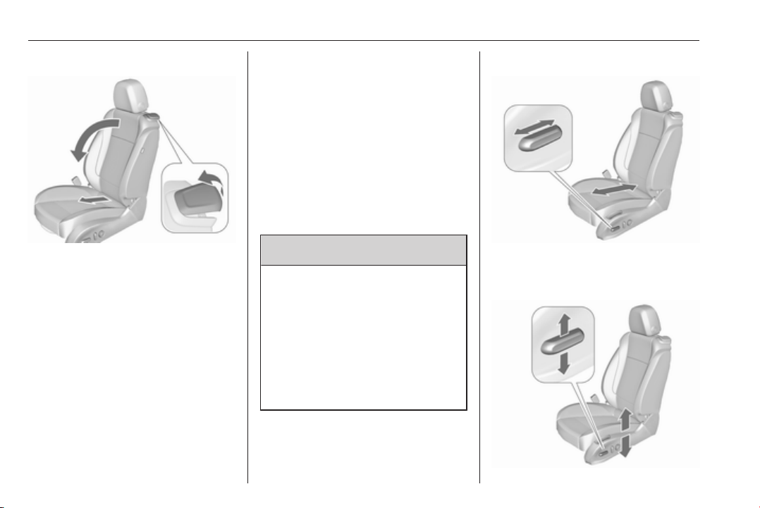
Seat folding on power seats
Lift release lever and fold backrest
forwards. The seat slides
automatically forwards to the stop.
To restore, lift backrest to upright
position and engage. The seat slides
automatically backwards to the
original position.
In case the head restraint of the
folded backrest is blocked by the
upper windscreen frame, allow the
seat to move backwards slightly
before lifting up the backrest 3 48.
Safety function
If the power seat encounters
resistance while sliding forward or
rearward, it is immediately stopped
and moved back.
Overload
If the folding function is electrically
overloaded, the power supply is
automatically cut-off for a short time.
Power seat adjustment
9 Warning
Care must be taken when
operating the power seats. There
is a risk of injury, particularly for
children. Objects could become
trapped.
Keep a close watch on the seats
when adjusting them. Vehicle
passengers should be informed
accordingly.
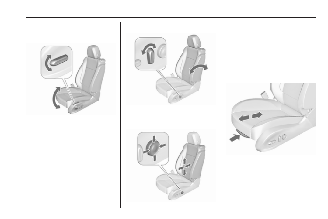
Seat lengthwise position
Move switch forwards/backwards.
Seat height
Page 51
Seats, restraints 49
Move switch upwards/downwards.
Seat inclination
Move front of switch upwards/
downwards.
Seat backrests
Turn switch forwards/backwards.
Lumbar support
Adjust lumbar support using the
four-way switch to suit personal
requirements.
Moving support up and down: push
switch up or down.
Increasing and decreasing support:
push switch forwards or backwards.
Adjustable thigh support
Pull the lever and slide the thigh
support.
Overload
If the seat setting is electrically
overloaded, the power supply is
automatically cut-off for a short time.
Page 52
50 Seats, restraints
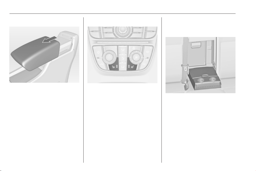
Armrest
The armrest can be slid forwards by
10 cm. Under the armrest there is a
storage compartment.
Armrest storage 3 65.
Heating
Adjust heating to the desired setting
by pressing ß for the respective seat
one or more times. The control
indicator in the button indicates the
setting.
Prolonged use of the highest setting
for people with sensitive skin is not
recommended.
Seat heating is operational when
engine is running and during an
Autostop.
Stop-start system 3 170.
Rear seats
Armrest
Fold armrest down. The armrest
contains cupholders and a storage
box.
Page 53
Seats, restraints 51
Seat belts
The seat belts are locked during hard
acceleration or deceleration of the
vehicle holding the occupants in the
sitting position. Therefore the risk of
injury is considerably reduced.
9 Warning
Fasten seat belt before each trip.
In the event of an accident, people
not wearing seat belts endanger
their fellow occupants and
themselves.
Seat belts are designed to be used by
only one person at a time. Child
restraint system 3 58.
Periodically check all parts of the belt
system for damage, pollution and
proper functionality.
Have damaged components
replaced. After an accident, have the
belts and triggered belt pretensioners
replaced by a workshop.
9 Warning
The openings in the backrests of
the OPC seats are not designed to
mount or carry through any kind of
additional seat belts.
Note
Make sure that the belts are not
damaged by shoes or sharp-edged
objects or trapped. Prevent dirt from
getting into the belt retractors.
Seat belt reminder
Front seats are equipped with a seat
belt reminder, indicated for driver seat
by control indicator X in the
tachometer 3 116 and for passenger
seat by the control indicators in the
centre console 3 113.
Belt force limiters
On the front seats, stress on the body
is reduced by the gradual release of
the belt during a collision.
Belt pretensioners
In the event of a head-on or rear-end
collision of a certain severity, the front
seat belts are tightened.
9 Warning
Incorrect handling (e.g. removal or
fitting of belts) can trigger the belt
pretensioners.
Deployment of the belt pretensioners
is indicated by continuous illumination
of control indicator v 3 116.
Page 54
52 Seats, restraints
Triggered belt pretensioners must be
replaced by a workshop. Belt
pretensioners can only be triggered
once.
Note
Do not affix or install accessories or
other objects that may interfere with
the operation of the belt
pretensioners. Do not make any
modifications to belt pretensioner
components as this will invalidate
the vehicle type approval.
Three-point seat belt
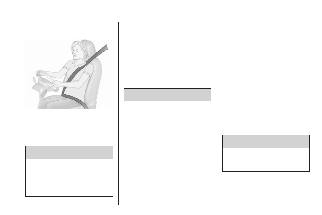
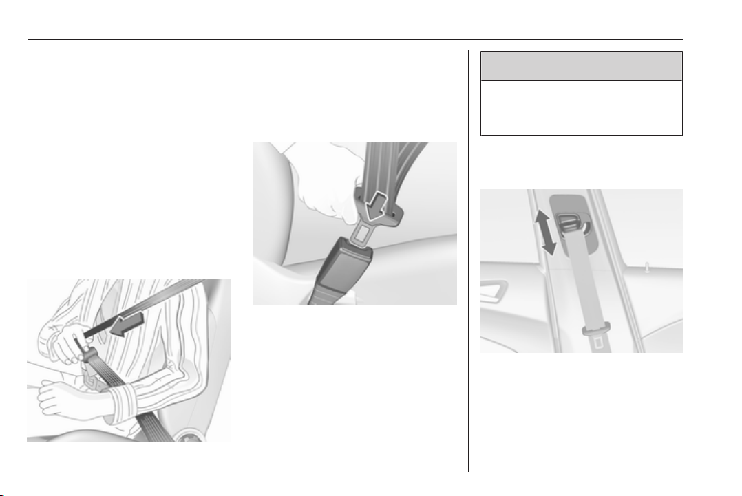
Fasten
Withdraw the belt from the retractor,
guide it untwisted across the body
and insert the latch plate into the
buckle. Tighten the lap belt regularly
whilst driving by pulling the shoulder
belt.
Loose or bulky clothing prevents the
belt from fitting snugly. Do not place
objects such as handbags or mobile
phones between the belt and your
body.
9 Warning
The belt must not rest against hard
or fragile objects in the pockets of
your clothing.
Seat belt reminder X 3 116.
Height adjustment
1. Pull belt out slightly.
2. Shift the height adjuster upwards
or press button to disengage and
push the height adjuster
downwards.
Page 55
Seats, restraints 53
Adjust the height so that the belt lies
across the shoulder. It must not lie
across the throat or upper arm.
Do not adjust while driving.
Unfasten
To release belt, press red button on
belt buckle.
Seat belts on the rear seats
The seat belt for the rear centre seat
can only be withdrawn from the
retractor if the backrest is engaged in
upright position.
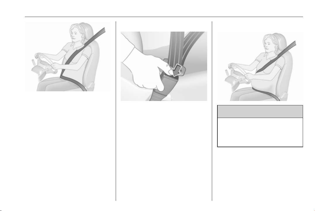
Using the seat belt while pregnant
9 Warning
The lap belt must be positioned as
low as possible across the pelvis
to prevent pressure on the
abdomen.
Page 56
54 Seats, restraints
Airbag system
The airbag system consists of a
number of individual systems
depending on the scope of
equipment.
When triggered, the airbags inflate
within milliseconds. They also deflate
so quickly that it is often unnoticeable
during the collision.
9 Warning
If handled improperly the airbag
systems can be triggered in an
explosive manner.
Note
The airbag systems and belt
pretensioner control electronics are
located in the centre console area.
Do not put any magnetic objects in
this area.
Do not affix any objects onto the
airbag covers and do not cover them
with other materials.
Each airbag is triggered only once.
Have deployed airbags replaced by
a workshop. Furthermore, it may be
necessary to have the steering
wheel, the instrument panel, parts of
the panelling, the door seals,
handles and the seats replaced.
Do not make any modifications to
the airbag system as this will
invalidate the vehicle type approval.
When the airbags inflate escaping hot
gases may cause burns.
Control indicator v for airbag systems
3 116.
Front airbag system
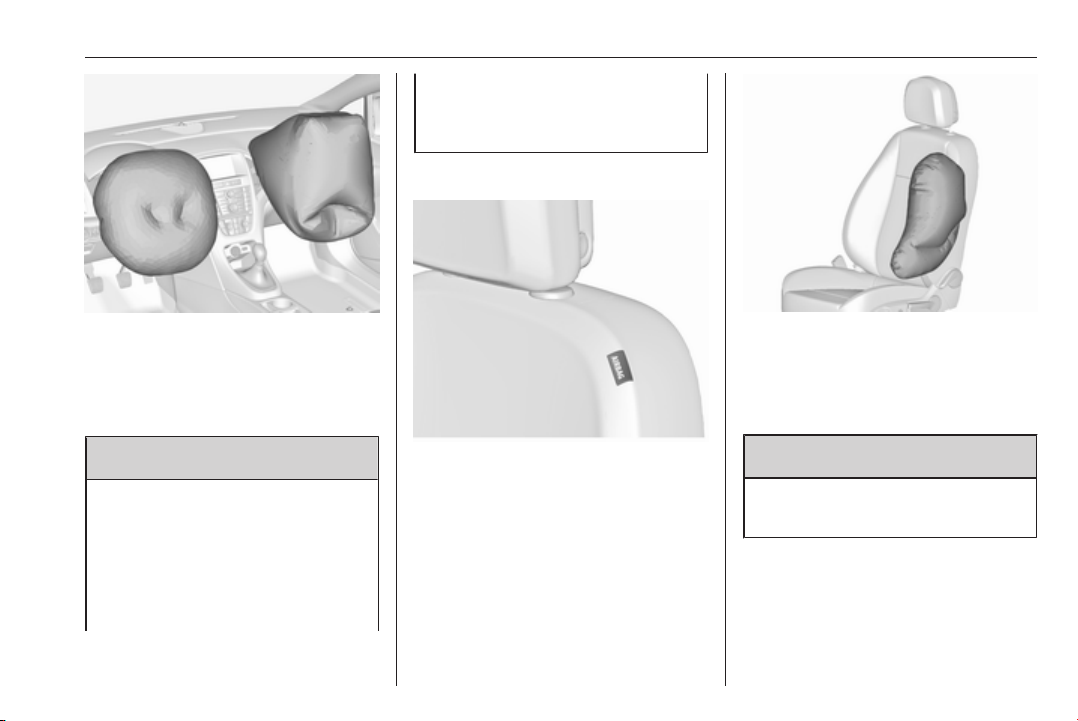
The front airbag system consists of
one airbag in the steering wheel and
one in the instrument panel on the
front passenger side. These can be
identified by the word AIRBAG.
Additionally, there is a warning label
on the side of the instrument panel,
visible when the front passenger door
is open, or on the front passenger sun
visor.
The front airbag system is triggered in
the event of a front-end impact of a
certain severity. The ignition must be
switched on.
Page 57
Fit the seat belt correctly and
engage securely. Only then is the
airbag able to protect.
Side airbag system
Seats, restraints 55
The inflated airbags cushion the
impact, thereby reducing the risk of
injury to the upper body and head of
the front seat occupants
considerably.
9 Warning
Optimum protection is only
provided when the seat is in the
proper position.
Seat position 3 41.
Keep the area in which the airbag
inflates clear of obstructions.
The side airbag system consists of an
airbag in each front seat backrest.
This can be identified by the word
AIRBAG.
The side airbag system is triggered in
the event of a side impact of a certain
severity. The ignition must be
switched on.
The inflated airbags cushion the
impact, thereby reducing the risk of
injury to the upper body and pelvis in
the event of a side-on collision
considerably.
9 Warning
Keep the area in which the airbag
inflates clear of obstructions.
Note
Only use protective seat covers that
have been approved for the vehicle.
Be careful not to cover the airbags.
Page 58
56 Seats, restraints
Curtain airbag system
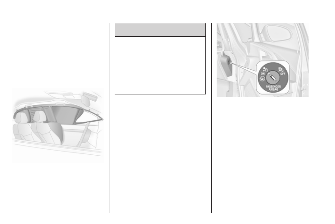
The curtain airbag system consists of
an airbag in the roof frame on each
side. This can be identified by the
word AIRBAG on the roof pillars.
The curtain airbag system is triggered
in the event of a side-on impact of a
certain severity. The ignition must be
switched on.
The inflated airbags cushion the
impact, thereby reducing the risk of
injury to the head in the event of a
side-on impact considerably.
Warning
9
Keep the area in which the airbag
inflates clear of obstructions.
The hooks on the handles in the
roof frame are only suitable for
hanging up light articles of
clothing, without coat hangers. Do
not keep any items in these
clothes.
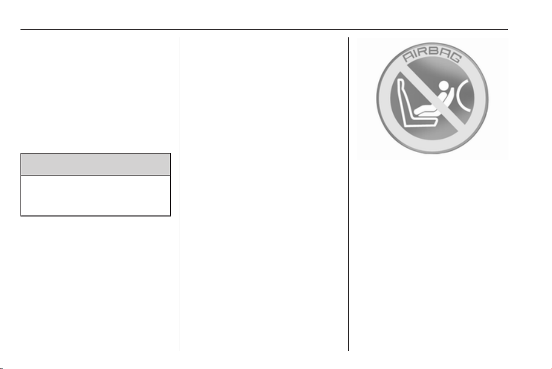
Airbag deactivation
The front passenger airbag system
must be deactivated if a child restraint
system is to be fitted on this seat. The
side airbag and curtain airbag
systems, the belt pretensioners and
all driver airbag systems will remain
active.
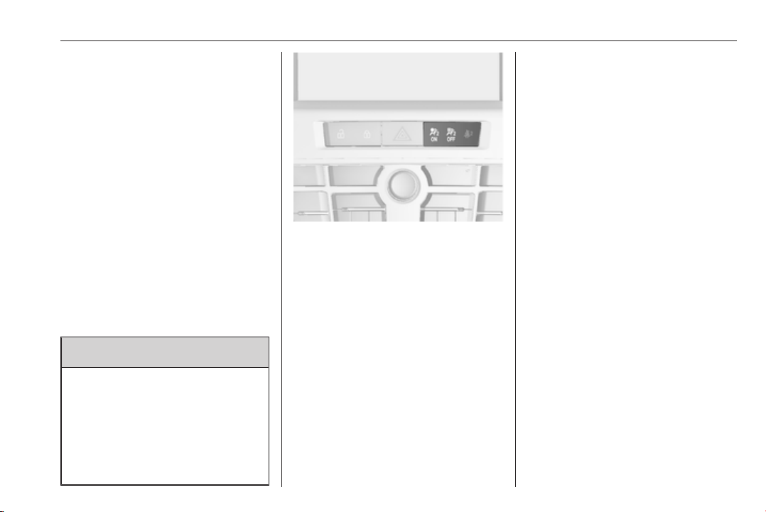
The front passenger airbag system
can be deactivated via a keyoperated switch on the right side of
the instrument panel.
Page 59
Seats, restraints 57
Use the ignition key to choose the
position:
*OFF
VON : front passenger airbag is
: front passenger airbag is
deactivated and will not
inflate in the event of a
collision. Control indicator
*OFF illuminates
continuously in the centre
console. A child restraint
system can be installed in
accordance with the chart
Child restraint installation
locations 3 59. No adult
person is allowed to occupy
the front passenger seat
active. A child restraint
system must not be
installed
9 Danger
Risk of fatal injury for a child using
a child restraint system on a seat
with activated front passenger
airbag.
Risk of fatal injury for an adult
person on a seat with deactivated
front passenger airbag.
Control indicator for airbag
deactivation 3 116.
If the control indicator V illuminates
for approx. 60 seconds after the
ignition is switched on, the front
passenger airbag system will inflate
in the event of a collision.
If both control indicators are
illuminated at the same time, there is
a system failure. The status of the
system is not discernible, therefore
no person is allowed to occupy the
front passenger seat. Contact a
workshop immediately.
Change status only when the vehicle
is stopped with the ignition off.
Status remains until the next change.
Page 60

58 Seats, restraints
Child restraints
Child restraint systems
We recommend the Opel child
restraint system which is tailored
specifically to the vehicle.
When a child restraint system is being
used, pay attention to the following
usage and installation instructions
and also those supplied with the child
restraint system.
Always comply with local or national
regulations. In some countries, the
use of child restraint systems is
forbidden on certain seats.
9 Warning
When using a child restraint
system on the front passenger
seat, the airbag systems for the
front passenger seat must be
deactivated; if not, the triggering of
the airbags poses a risk of fatal
injury to the child.
This is especially the case if rearfacing child restraint systems are
used on the front passenger seat.
Airbag deactivation 3 56.
Airbag label 3 54.
Selecting the right system
The rear seats are the most
convenient location to fasten a child
restraint system.
Children should travel facing
rearwards in the vehicle as long as
possible. This makes sure that the
child's backbone, which is still very
weak, is under less strain in the event
of an accident.
Suitable are restraint systems that
comply with valid UN ECE
regulations. Check local laws and
regulations for mandatory use of child
restraint systems.
Ensure that the child restraint system
to be installed is compatible with the
vehicle type.
Ensure that the mounting location of
the child restraint system within the
vehicle is correct, see following
tables.
Allow children to enter and exit the
vehicle only on the side facing away
from the traffic.
When the child restraint system is not
in use, secure the seat with a seat belt
or remove it from the vehicle.
Note
Do not affix anything on the child
restraint systems and do not cover
them with any other materials.
A child restraint system which has
been subjected to stress in an
accident must be replaced.
Page 61
Seats, restraints 59
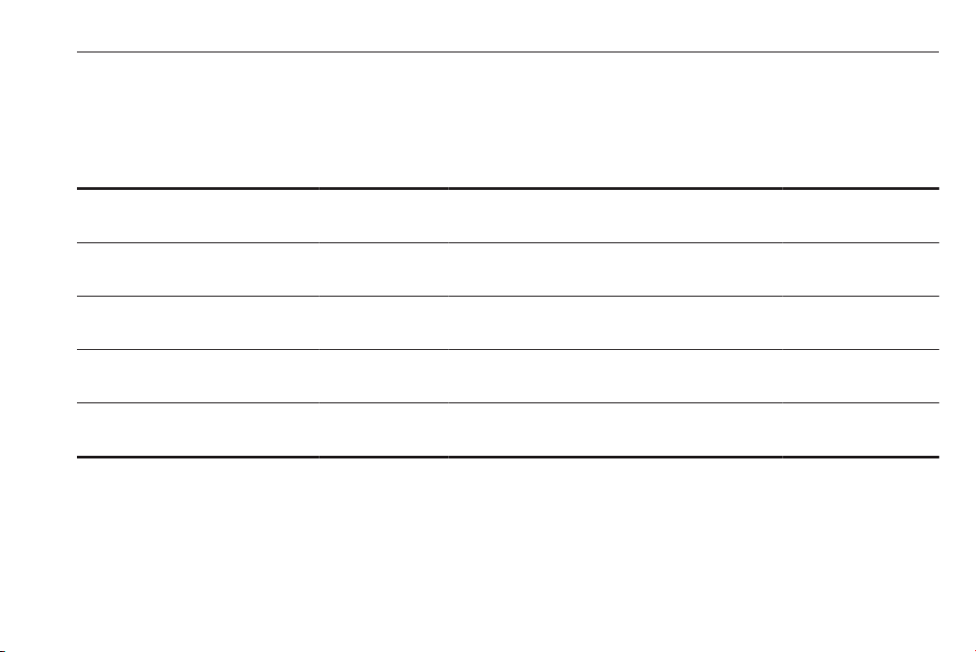
Child restraint installation locations
Permissible options for fitting a child restraint system
On front passenger seat
Weight and age class
Group 0: up to 10 kg
X
1
U
or approx. 10 months
Group 0+: up to 13 kg
X
1
U
or approx. 2 years
Group I: 9 to 18 kg
X
1
U
or approx. 8 months to 4 years
Group II: 15 to 25 kg
X X U U
or approx. 3 to 7 years
Group III: 22 to 36 kg
X X U U
or approx. 6 to 12 years
1
: if the child restraint system is being secured using a three-point seat belt, move seat height adjustment to uppermost
position and ensure that vehicle seat belt runs forwards from the upper anchorage point. Adjust seat backrest
inclination as far as necessary to a vertical position to ensure that the belt is tight on the buckle side.
U : universal suitability in conjunction with three-point seat belt.
X : no child restraint system permitted in this weight class.
On rear outboard seats On rear centre seatactivated airbag deactivated airbag
U U
U U
U U
Page 62

60 Seats, restraints
Permissible options for fitting an ISOFIX child restraint system
Weight class Size class Fixture
Group 0: up to 10 kg
or approx. 10 months
Group 0+: up to 13 kg
or approx. 2 years
Group I: 9 to 18 kg
or approx. 8 months to 4 years
Group II: 15 to 25 kg
or approx. 3 to 7 years
Group III: 22 to 36 kg
or approx. 6 to 12 years
E ISO/R1 X IL X
E ISO/R1 X IL X
D ISO/R2 X IL X
C ISO/R3 X IL X
D ISO/R2 X IL X
C ISO/R3 X IL X
B ISO/F2 X IL, IUF X
B1 ISO/F2X X IL, IUF X
A ISO/F3 X IL, IUF X
On front passenger
seat
X IL X
X IL X
On rear outboard
seats On rear centre seat
Page 63

Seats, restraints 61
IL : suitable for particular ISOFIX restraint systems of the 'specific-vehicle', 'restricted' or 'semi-universal' categories.
The ISOFIX restraint system must be approved for the specific vehicle type.
IUF : suitable for ISOFIX forward-facing child restraint systems of universal category approved for use in this weight class.
X : no ISOFIX child restraint system approved in this weight class.
ISOFIX size class and seat device
A – ISO/F3 : forward-facing child restraint system for children of maximum size in the weight class 9 to 18 kg
B – ISO/F2 : forward-facing child restraint system for smaller children in the weight class 9 to 18 kg
B1 – ISO/F2X : forward-facing child restraint system for smaller children in the weight class 9 to 18 kg
C – ISO/R3 : rear-facing child restraint system for children of maximum size in the weight class up to 18 kg
D – ISO/R2 : rear-facing child restraint system for smaller children in the weight class up to 18 kg
E – ISO/R1 : rear-facing child restraint system for young children in the weight class up to 13 kg
Page 64
62 Seats, restraints
ISOFIX child restraint systems
Fasten vehicle-approved ISOFIX
child restraint systems to the ISOFIX
mounting brackets. Specific vehicle
ISOFIX child restraint system
positions are marked in the table by
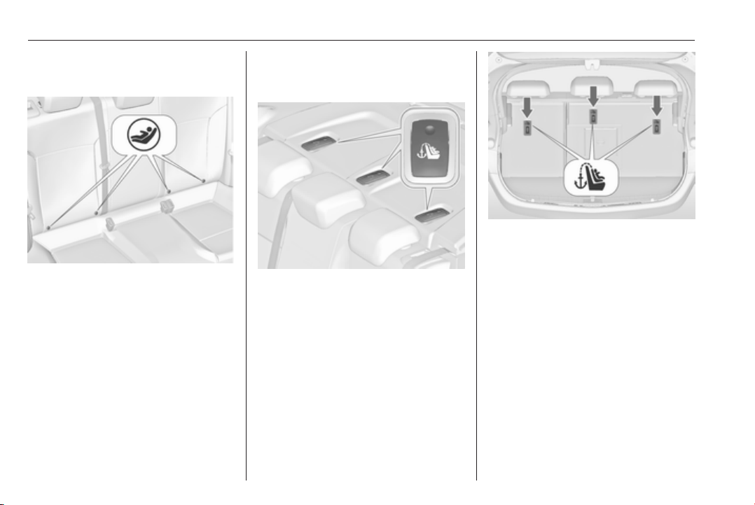
IL.
ISOFIX mounting brackets are
indicated by a label on the backrest.
Top-tether fastening eyes
Depending on country specific
equipment, the vehicle might have
two or three fastening eyes.
Top-Tether fastening eyes are
marked with the symbol : for a child
seat.
On Notchback version, open the flap
of the required fastening eye on the
placement area behind the head
restraints, marked by the child seat
symbol.
On Hatchback and Sports Tourer,
fastening eyes are on the backside of
rear seats.
In addition to the ISOFIX mounting,
fasten the Top-Tether strap to the
Top-Tether fastening eyes. The strap
must run between the two guide rods
of the head restraint.
ISOFIX child restraint systems of
universal category positions are
marked in the table by IUF.
Page 65
Storage 63
Storage
Storage compartments ................ 63
Glovebox ................................... 63
Cupholders ................................ 63
Front storage ............................. 64
Underseat storage ..................... 65
Armrest storage ......................... 65
Centre console storage ............. 66
Rear carrier system ................... 67
Load compartment ....................... 84
Rear storage .............................. 88
Load compartment cover ........... 88
Rear floor storage cover ............ 90
Lashing eyes ............................. 93
Cargo management system ......93
Safety net .................................. 95
Warning triangle ........................ 96
First aid kit ................................. 97
Roof rack system ......................... 98
Roof rack ................................... 98
Loading information ..................... 99
Storage compartments
9 Warning
Do not store heavy or sharp
objects in the storage
compartments. Otherwise, the
storage compartment lid could
open and vehicle occupants could
be injured by objects being thrown
around in the event of hard
braking, a sudden change in
direction or an accident.
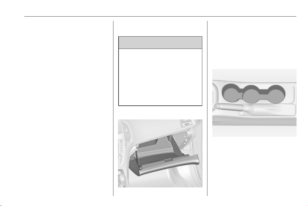
Glovebox
The glovebox features a pen holder,
a credit card holder, a coin holder and
an adapter for the locking wheel nuts.
The glovebox should be closed whilst
driving.
Cupholders
Cupholders are located in the centre
console.
Page 66
64 Storage
Front storage
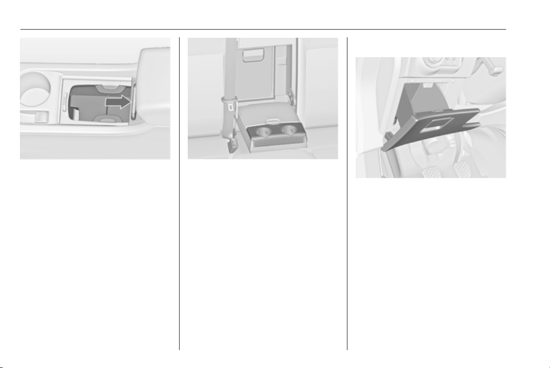
Depending on the version,
cupholders are located under a cover
in the centre console. Slide cover
backwards. Bottles can be stowed
after folding up the intermediate shelf
3 66.
Additional cupholders are located in
the rear armrest. Fold down the
armrest.
A storage compartment is located
next to the steering wheel.
Page 67
Storage 65
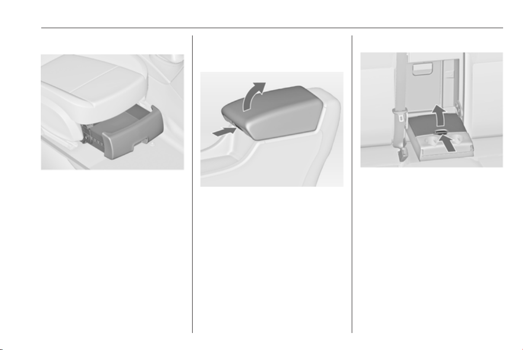
Underseat storage
Press button in the recess and pull out
drawer. Maximum load: 3 kg. To
close, push in and engage.
On version with rear carrier system
3 67, the tyre repair kit is stowed in
the drawer.
Tyre repair kit 3 272.
Armrest storage
Storage under the front armrest
Press button to fold up the armrest.
The armrest must be in rearmost
position.
Storage in the rear armrest
Fold down armrest and open cover.
Close cover before folding the
armrest up.
Page 68
66 Storage
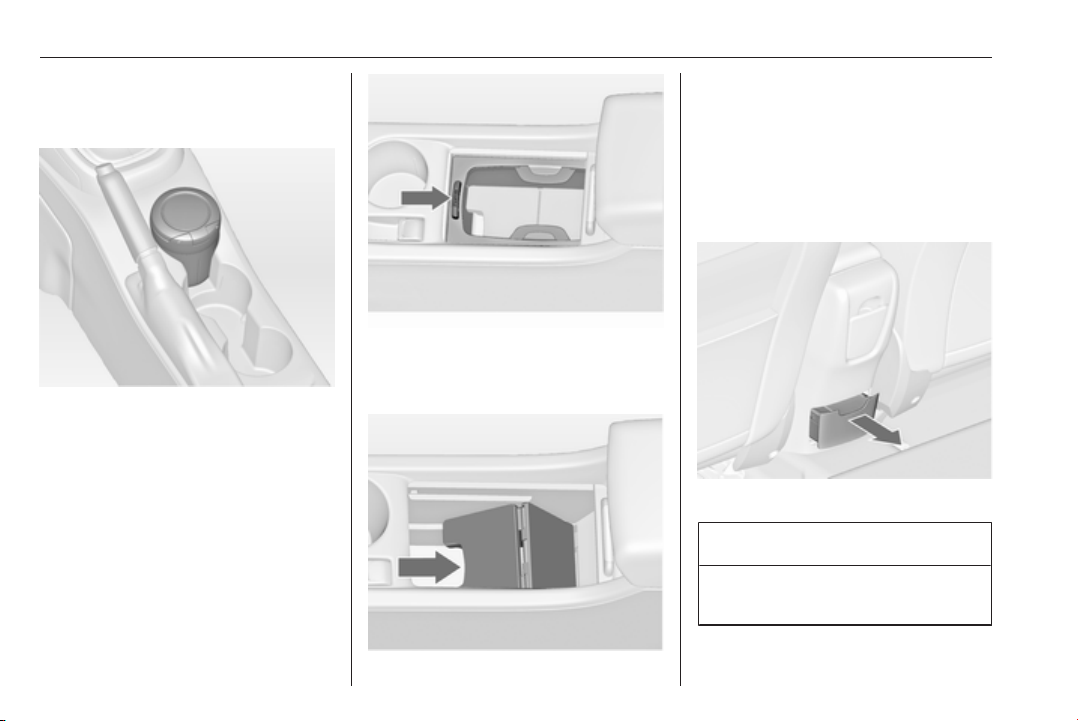
Centre console storage
Front console
The storage container can be used to
store small items.
Depending on the version, a storage
compartment is located under a
cover.
Slide cover backwards.
A further storage compartment is
located under the intermediate shelf.
Fold up the intermediate shelf and fix
it in the vertical position. The frame of
the cupholder can be reintegrated to
stow bottles.
Rear console
Press button to remove the frame of
the cupholder. The frame can be
stowed in the glovebox.
Pull out the drawer.
Caution
Do not use for ash or for other
combustible items.
Page 69
Storage 67
Rear carrier system
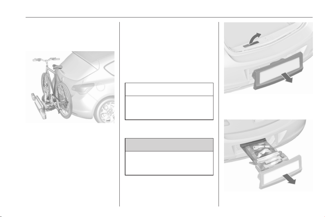
Rear carrier system for two bicycles
The rear carrier system (Flex-Fix
system) allows bicycles to be
attached to a pull-out carrier
integrated into the vehicle floor. The
transportation of other objects is not
permitted.
The maximum load of the rear carrier
system is 40 kg. The maximum load
per bicycle is 20 kg.
The wheelbase of a bicycle must not
exceed 1.2 metres. Otherwise the
secure fastening of a bicycle is not
possible.
If not in use, the carrier system must
be slid back into the vehicle floor.
There must not be any objects on the
bicycles that could become loose
during transportation.
Caution
Do not attach bicycles with carbon
pedal cranks to bicycle carriers.
The bicycles may get damaged.
Extending
Open the tailgate.
9 Warning
No-one should be in the extension
zone of the rear carrier system,
risk of injury.
Pull release lever up. The system
disengages and travels quickly out of
the bumper.
Page 70
68 Storage
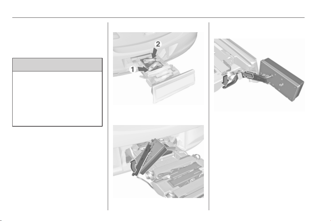
Completely pull out the rear carrier
system until you hear it engage.
Ensure that it is not possible to push
in the rear carrier system without
pulling the release lever again
9 Warning
It is only permissible to fit objects
to the rear carrier system if the
system has been correctly
engaged. If the rear carrier system
will not engage correctly, do not fit
objects to the system and slide the
system back. Seek the assistance
of a workshop.
Install the tail lamps
First remove the rear (1), then the
front (2) tail lamp from the recesses.
Open out the lamp support on the
back of the tail lamp completely.
Push the clamping lever down and
push the lamp support into the
retainer until it engages.
Perform this procedure for both tail
lamps.
Page 71
Storage 69
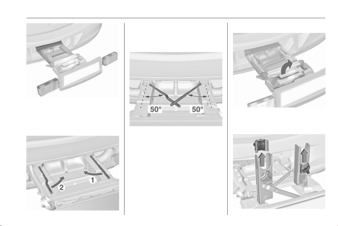
Check the cable and lamp position to
ensure these are correctly installed
and are securely located.
Lock the rear carrier system
Swivel the right clamping lever (1)
first, followed by the left clamping
lever (2), until a resistance is
noticeable.
The rear carrier system is locked
when the clamping levers are
swivelled by approx. 50°. Otherwise
safe functionality is not guaranteed.
Note
Close the tailgate.
Unfold pedal crank recesses
Fold one or both pedal crank
recesses upwards until the diagonal
support engages.
Page 72
70 Storage
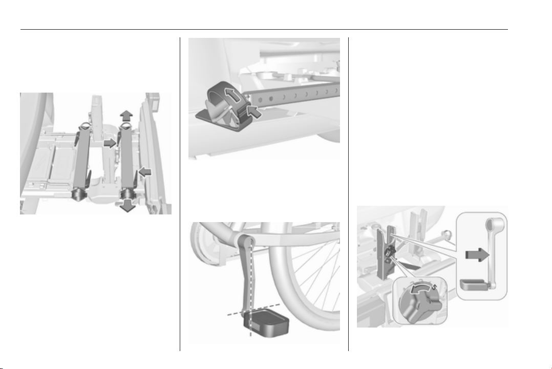
Remove the pedal crank mounts from
the pedal crank recesses.
Adapting the rear carrier system to a bicycle
Press the release lever and withdraw
the wheel recesses.
Push the release lever on the strap
retainer and remove the strap
retainer.
Prepare the bicycle for attachment
Note
The maximum width for the pedal
crank is 38.3 mm and the maximum
depth is 14.4 mm.
Rotate the left pedal (without a chain
cog) vertically downwards. The pedal
on the left pedal crank must be
horizontal.
The front bicycle must have its front
wheel facing left.
The rear bicycle must have its front
wheel facing right.
Attaching a bicycle to the rear carrier system
Page 73
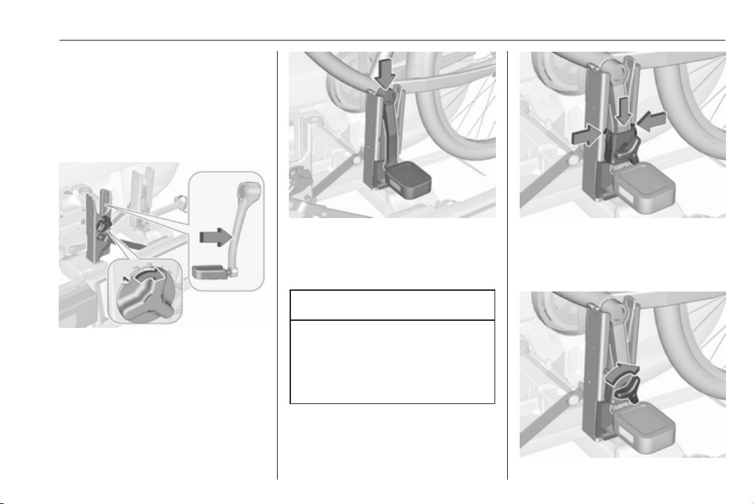
With the rotary lever on the pedal
crank recess, roughly adapt the
adjustable pedal crank unit to the
protrusion of the pedal crank.
If the bicycle has straight pedal
cranks, unscrew the pedal crank unit
completely (position 5).
Storage 71
If the bicycle has curved pedal
cranks, screw in the pedal crank unit
all the way (position 1).
Put on the bicycle. The pedal crank
here must be placed in the pedal
crank recess opening, as shown in
the illustration.
Caution
Ensure that the pedal does not
touch the surface of the rear end
carrier. Otherwise the crankset
may be damaged during the
transport.
Insert pedal crank mount into outer
rail of each pedal crank recess from
above and slide downwards until at
least underneath the notching.
Page 74
72 Storage
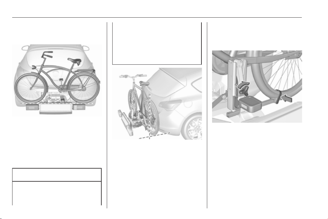
Attach the pedal crank by rotating the
attachment screw on the pedal crank
mount.
Place the wheel recesses such that
the bicycle is more or less horizontal.
Here, the distance between the
pedals and the tailgate should be at
least 5 cm.
Both bicycle tyres must be in the
wheel recesses.
Caution
Make sure to pull out the wheel
recesses as far as necessary to
have both bicycle tyres placed in
the recesses. Otherwise a
horizontal mounting of the bicycle
is not ensured. Disregard could
lead to damage of the bicycle
wheels caused by hot exhaust
fumes.
Align the bicycle in the longitudinal
direction of the vehicle: Slightly
loosen the pedal mount.
Place the bicycle upright using the
rotary lever on the pedal crank
recess.
If the two bicycles obstruct one
another, the relative positions of the
bicycles can be adapted by adjusting
the wheel recesses and the rotary
lever on the pedal crank recess until
the bicycles no longer touch one
another. Make sure there is sufficient
clearance from the vehicle.
Tighten the attachment screw for the
pedal bearing mount to its maximum
point by hand.
Secure both bicycle wheels to the
wheel recesses using the strap
retainers.
Check the bicycle to make sure it is
secure.
Page 75
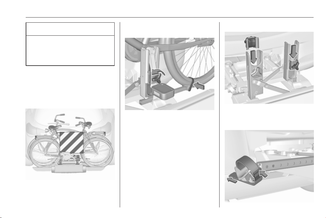
Storage 73
Caution
Ensure gap between bicycle and
vehicle is at least 5 cm. If
necessary, loosen handlebar and
swivel sideways.
The settings for the wheel recesses
and on the rotary lever on the pedal
crank recess should be noted and
saved for each bicycle. Correct
presetting will facilitate refitting of the
bicycle.
It is recommended to attach a
warning sign at the rearmost bicycle
to increase visibility.
Removing a bicycle from the rear carrier system
Undo strap retainers on both bicycle
tyres.
Hold on to the bicycle, loosen the
attachment screw for the pedal
bearing mount, then lift the pedal
bearing mount to remove it.
Retracting the rear carrier system
Push the pedal crank mounts into the
pedal crank recess, as shown in the
illustration.
Page 76
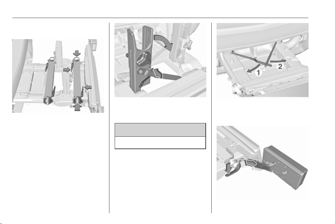
74 Storage
Insert the strap retainer and pull
tightly downwards as far as possible.
Press release lever and slide in wheel
recesses all the way as far as they will
go.
Disengage the locking lever on the
diagonal support and fold both pedal
crank recesses down.
9 Warning
Risk of pinching.
Swivel first the left clamping lever (1),
followed by the right clamping lever
(2), until they stop.
Page 77
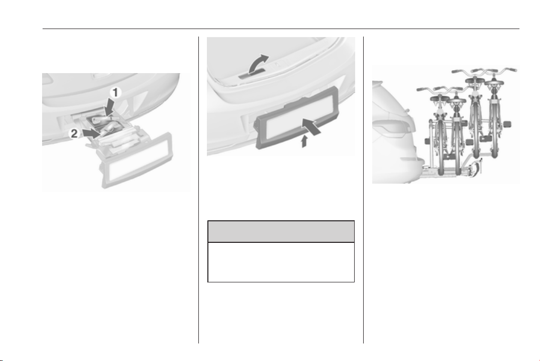
Storage 75
Push the clamping lever down and
pull both lamp supports out of the
recesses.
Fold in the lamp supports on the
backs of the tail lamps.
First place the front (1) tail lamp, then
the rear (2) tail lamp in the recesses
and push down as far as possible.
Push cables all the way into all guides
in order to prevent damage.
Open the tailgate.
Push the release lever up and hold.
Lift the system slightly and push it into
the bumper until it engages.
Release lever must return to original
position.
9 Warning
If the system cannot be correctly
engaged, please seek the
assistance of a workshop.
Rear carrier system for four bicycles
The rear carrier system (Flex-Fix
system) allows two bicycles to be
attached to a pull-out carrier
integrated into the vehicle floor. It is
possible to attach two further bicycles
on an adapter. The transportation of
other objects is not permitted.
The maximum load of the rear carrier
system is 80 kg with attached adapter
and 60 kg without attached adapter.
The maximum load per bicycle on the
pull-out carrier is 30 kg. This allows
the attachment of electrically-
Page 78
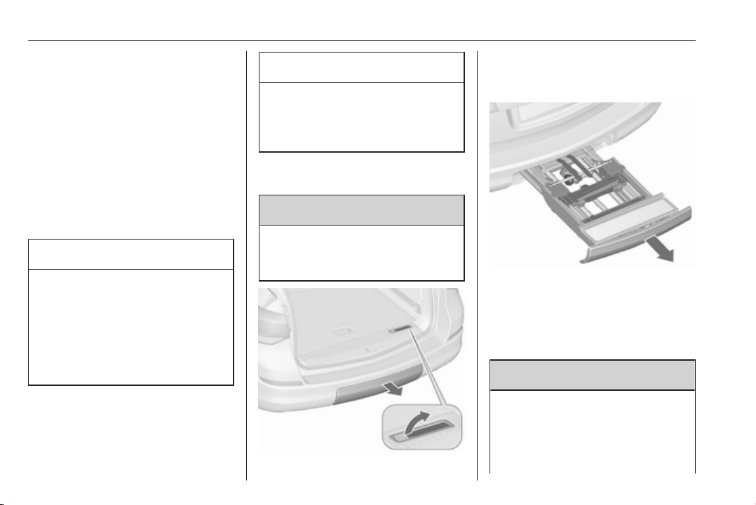
76 Storage
powered bicycles to the pull-out
carrier. The maximum load per
bicycle on the adapter is 20 kg.
The wheelbase of a bicycle must not
exceed 1.15 metres. Otherwise the
secure fastening of a bicycle is not
possible.
If not in use, the carrier system must
be slid back into the vehicle floor.
There must not be any objects on the
bicycles that could become loose
during transportation.
Caution
If the rear carrier system is
extended and the vehicle is fully
loaded, the chassis clearance will
be reduced.
Drive carefully whenever the road
has a strong inclination or when
driving over a ramp, bump, etc.
Caution
Consult your bicycle dealer before
attaching bicycles with carbon
frames. The bicycles may get
damaged.
Extending
Open the tailgate.
9 Warning
No-one should be in the extension
zone of the rear carrier system,
risk of injury.
Pull release lever up. The system
disengages and travels quickly out of
the bumper.
Completely pull out the rear carrier
system until you hear it engage.
Ensure that it is not possible to push
in the rear carrier system without
pulling the release lever again.
9 Warning
It is only permissible to fit objects
to the rear carrier system if the
system has been correctly
engaged. If the rear carrier system
will not engage correctly, do not fit
Page 79
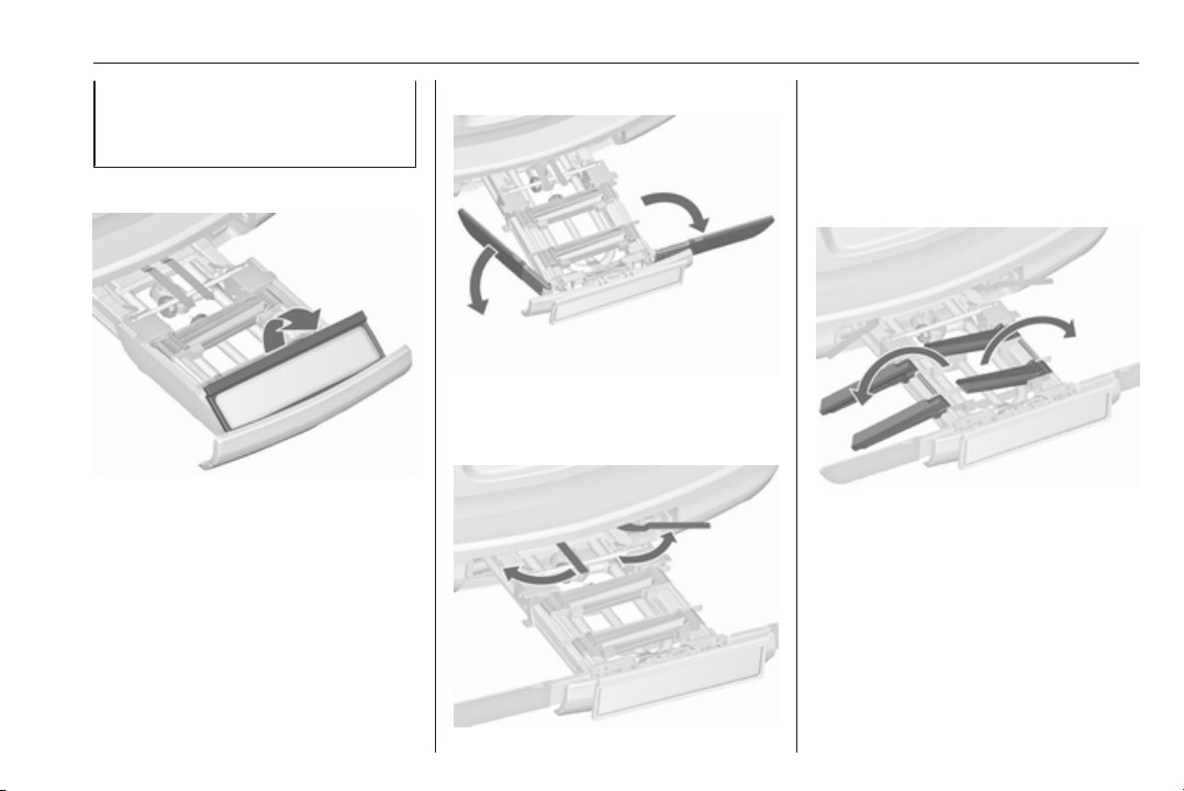
Storage 77
objects to the system and slide the
system back. Seek the assistance
of a workshop.
Unfold number plate holder
Lift the number plate holder and fold
it backwards.
Fold out tail lamps
Fold out both tail lamps.
Lock the rear carrier system
Swivel both clamping levers
sidewards as far as they will go.
Otherwise safe functionality is not
guaranteed.
Fold out wheel recesses
Fold out both wheel recesses.
Page 80
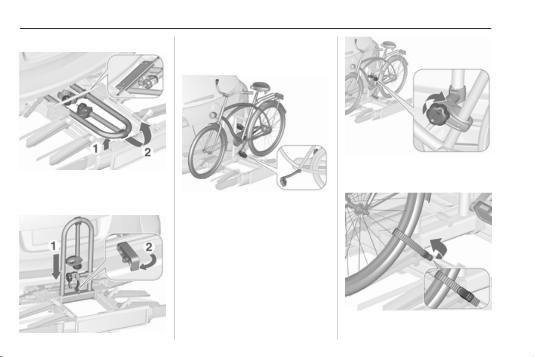
78 Storage
Assembling the bicycle rack
Lift the rack at the rear (1) and pull it
backwards.
Fold up the rack (2).
Push down the rack (1) and swivel
handle (2) backwards to engage.
Attaching the first bicycle
2. Attach the short mounting bracket
to the bicycle frame. Turn the
knob clockwise to fasten.
1. Rotate the pedals into position (as
shown in the illustration) and put
the bicycle on the foremost wheel
recess.
Make sure that the bicycle stands
centrally on the wheel recesses.
Page 81
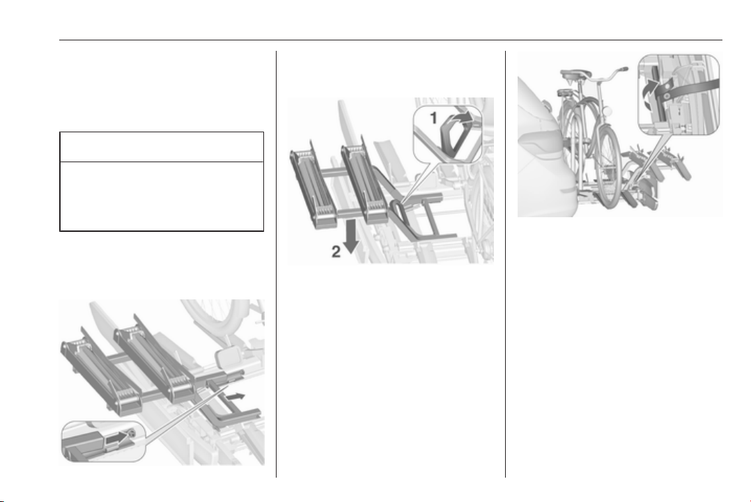
Storage 79
3. Secure both bicycle wheels to the
wheel recesses using the strap
retainers.
4. Check the bicycle to make sure it
is secure.
Caution
Ensure gap between bicycle and
vehicle is at least 5 cm. If
necessary, loosen handlebar and
swivel sidewards.
Attaching the adapter
When carrying more than two
bicycles, the adapter must be fixed
before the second bicycle is attached.
1. Apply the adapter to the rear
carrier system as shown in the
illustration.
2. Turn the lever (1) forwards and
hold, then lower the adapter (2) at
the rear.
3. Release lever and check if the
adapter is engaged securely.
4. Guide the strap attached to the
adapter underneath the lever for
folding back the rear carrier
system. Fasten the strap.
Attaching further bicycles
The attachment of further bicycles is
similar to the attachment of the first
bicycle. Additionally, some steps
must be considered:
1. Before putting on the bicycle,
always unfold the wheel recesses
for the next bicycle if necessary.
2. Always rotate the pedals into an
appropriate position before
putting on the bicycle.
Page 82
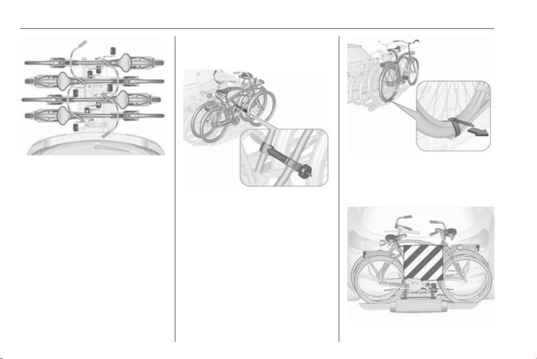
80 Storage
Use the longer accessory
mounting bracket to attach the
third bicycle to the rack.
3. Position the bicycles on the rear
carrier system alternately aligned
to the left and to the right.
4. Align the bicycles to the one
attached before. The wheel hubs
of the bicycles must not touch
each other.
5. Attach the bicycles with mounting
brackets and strap retainers as
described for the first bicycle. The
mounting brackets should be
fixed in parallel.
Use the long mounting bracket to
attach the second bicycle to the
rack.
Use the short accessory mounting
bracket to attach the fourth
bicycle. The bracket must be fixed
between the frames of the third
and fourth bicycle.
6. Additionally, secure both bicycle
wheels of the fourth bicycle to the
wheel recesses using the
tensioning straps.
Page 83
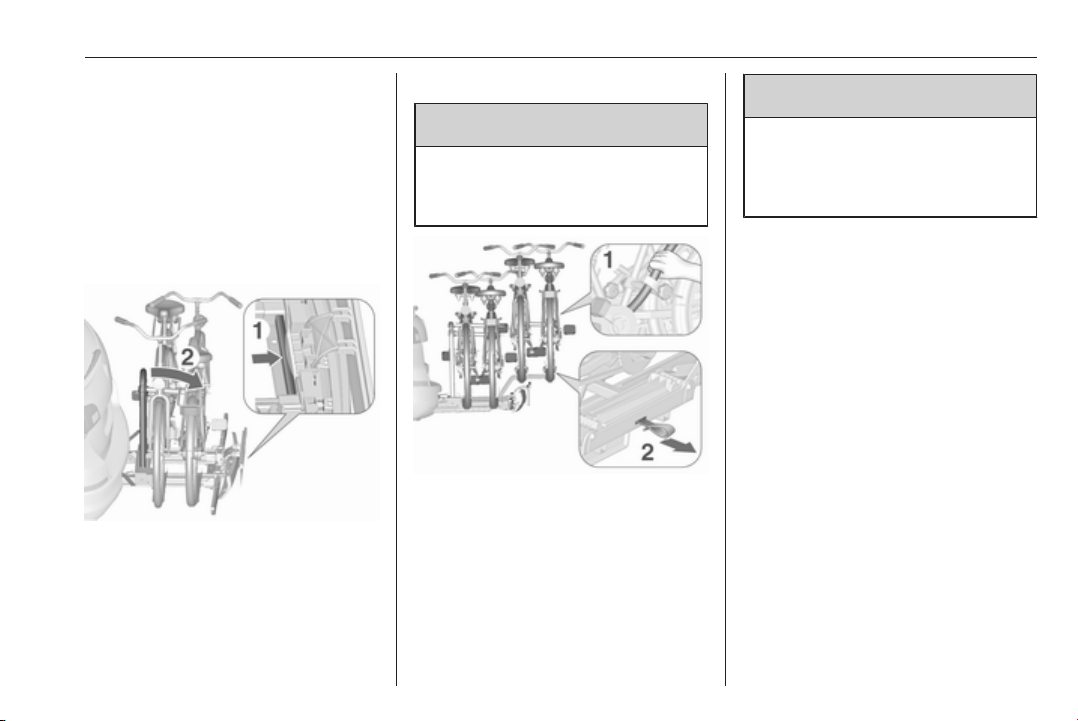
Storage 81
It is recommended to attach a
warning sign at the rearmost bicycle
to increase visibility.
Fold the rear carrier system backwards
The rear carrier system can be folded
backwards to get access to the load
compartment.
● Without attached adapter:
Push the lever (1) to disengage
and hold.
Pull the rack (2) backwards to
fold the rear carrier system.
● With attached adapter:
9 Warning
Take care when disengaging the
rear carrier system as it will tilt
backwards. Risk of injury.
Hold frame (1) of rearmost
bicycle with one hand and pull the
loop (2) to disengage.
Hold rearmost bicycle with both
hands and fold the rear carrier
system backwards.
To increase visibility, the tail lights of
the vehicle are activated when the
rear carrier system is folded back.
9
Warning
When folding the rear carrier
system forwards again, take care
that the system is engaged
securely.
Removing bicycles
Undo strap retainers on both bicycle
tyres.
Turn knob anti-clockwise and remove
mounting brackets.
Detaching adapter
Detach the adapter before removing
the last bicycle left on the rear carrier
system.
1. Fold in wheel recesses.
Page 84
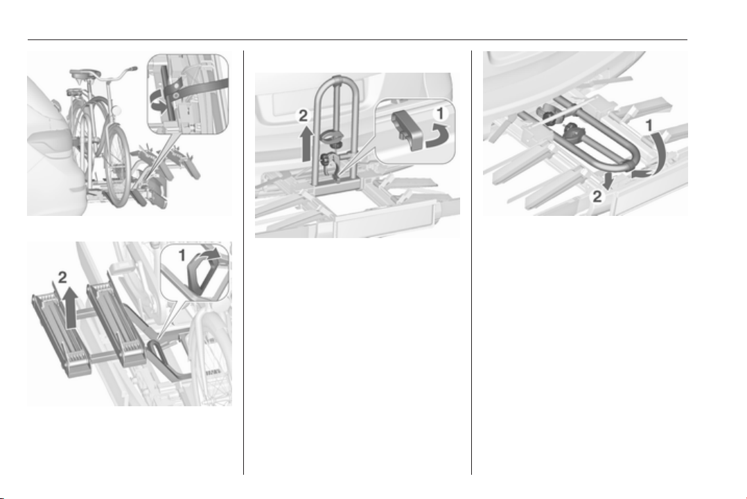
82 Storage
Disassembling the bicycle rack
2. Unbutton the strap.
3. Turn the lever (1) forwards and
hold.
4. Lift the adapter (2) at the rear and
remove.
Arrange mounting brackets as shown
in the illustration.
Swivel handle (1) forwards to
disengage and lift the rack (2).
Fold the rack backwards, then push
forwards until it stops (1).
Press the rack down at the rear (2).
Fold in wheel recesses
Fold in both wheel recesses.
Page 85
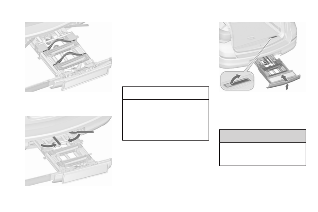
Swivel both clamping levers inwards
as far as they will go.
Fold in tail lamps
Swivel in both tail lamps.
Fold in number plate holder
Lift the number plate holder and fold
it forwards.
Retracting the rear carrier system
Storage 83
Stow the strap retainers accurately.
Unlock the rear carrier system
Caution
Take care that all foldable parts,
e.g. wheel recesses and mounting
brackets, are stowed accurately.
Otherwise the rear carrier system
may get damaged when trying to
retract it.
Push the release lever up and hold.
Lift the system slightly and push it into
the bumper until it engages.
Release lever must return to original
position.
9 Warning
If the system cannot be correctly
engaged, please seek the
assistance of a workshop.
Page 86
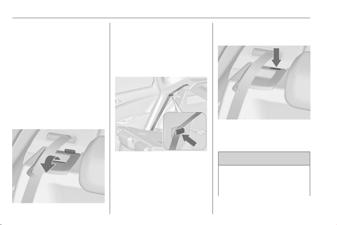
84 Storage
Load compartment
The rear seat backrest is divided into
two parts. Both parts can be folded
down.
Load compartment extension,
3-door and 5-door hatchback,
4-door notchback
● Only 3-door and 5-door
hatchback: remove the load
compartment cover if necessary.
● Press and hold the catch to push
the head restraints down 3 39.
● Fold up the rear armrest.
● Guide the seat belts through side
supports to protect them against
damage. When folding the
backrests, pull the seat belts
along with them.
● Pull the release lever on one or
both sides and fold down the
backrests onto the seat cushion.
● Take the seat belt out of the seat
backrest guide and put it behind
the retainer as shown in the
illustration.
To fold up, raise the backrests and
guide them into an upright position
until they engage audibly.
Ensure that the seat belts of the
outboard seats are placed in the
corresponding belt guides.
The backrests are properly engaged
when the red marks on both sides
near the release lever are no longer
visible.
9 Warning
When folding up, ensure that
backrests are securely locked in
position before driving. Failure to
do so may result in personal injury
Page 87
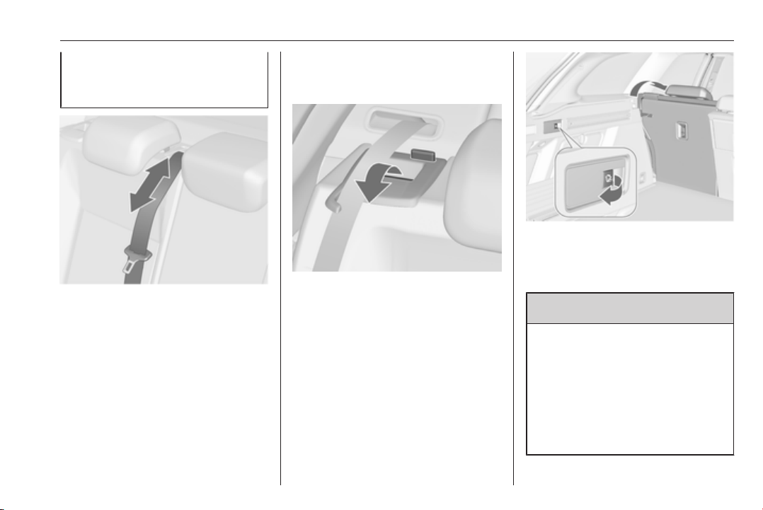
Storage 85
or damage to the load or vehicle in
the event of hard braking or a
collision.
The seat belt of the centre seat could
be blocked when the backrest is
folded up too quickly. To unlock the
retractor, push in the seat belt or pull
it out by approx. 20 mm then release.
Load compartment extension,
Sports tourer
Folding down rear backrests
● Remove the load compartment
cover if necessary.
● Press and hold the catch to push
the head restraints down 3 39.
● Fold up the rear armrest.
● Guide the seat belts through side
supports to protect them against
damage. When folding the
backrests, pull the seat belts
along with them.
● Pull the release lever on one or
both sides and fold down the
backrests onto the seat cushion.
Electric seat folding
On vehicles with electric seat folding,
the rear seats can also be folded from
the load compartment.
● Pull switch on left or right sidewall
of the load compartment to fold
the corresponding part of the rear
seat.
9 Warning
Take care when operating the
electric foldable rear seats. The
seat backrest is folded with
considerable power. Risk of injury,
particularly to children.
Ensure that nothing is attached to
the rear seats or located on the
seat cushion.
Page 88
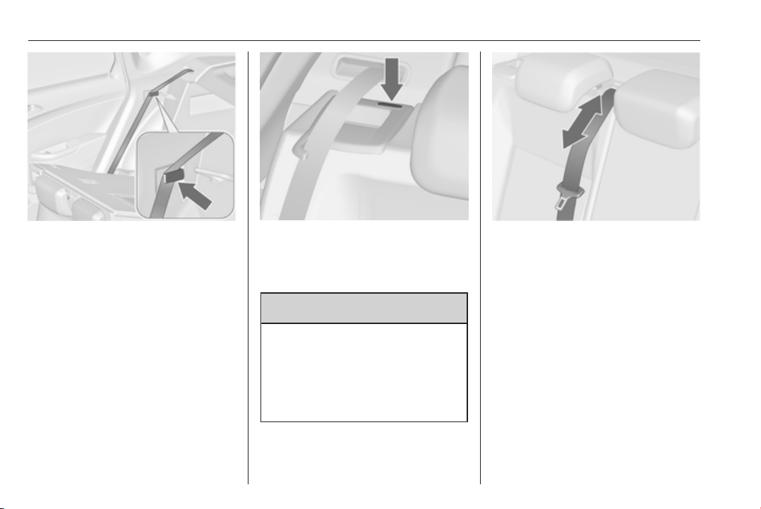
86 Storage
If the vehicle is to be loaded via a
rear door, take the seat belt out
of the seat backrest guide and
put it behind the retainer (as
shown in the illustration).
● To fold up, raise the backrests
and guide them into an upright
position until they engage
audibly.
Ensure that the seat belts of the
outboard seats are placed in the
corresponding belt guides.
The backrests are properly engaged
when the red marks on both sides
near the release lever are no longer
visible.
9 Warning
Only drive the vehicle if the
backrests are securely locked into
position. Otherwise there is a risk
of personal injury or damage to the
load or vehicle in the event of hard
braking or a collision.
The seat belt of the centre seat could
be blocked when the backrest is
folded up too quickly. To unlock the
retractor, push in the seat belt or pull
it out by approx. 20 mm then release.
Page 89
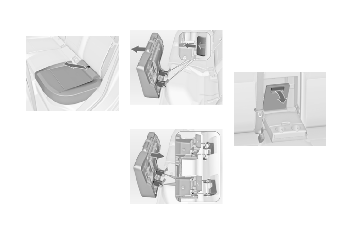
Storage 87
Raise the seat cushion and fold the
backrest
● Pull the loop on one or both seat
cushions and lift the rear of the
cushion forwards.
● Press and hold the catch to push
the head restraints down 3 39.
● Pull the release lever on one or
both sides of the backrests and
fold down onto the seat cushion
to get a flat load-bay.
Remove the seat cushion
● Push both levers forward and
remove seat cushion to extend
the loading area.
● To attach, apply seat cushion as
shown in the illustration and
engage both levers.
Open the pass-through in the rear
centre backrest
● Fold down the rear armrest.
● Pull the grip and open the cover.
Suitable for loading long, narrow
objects.
Ensure that the cover engages after
folding up.
Page 90
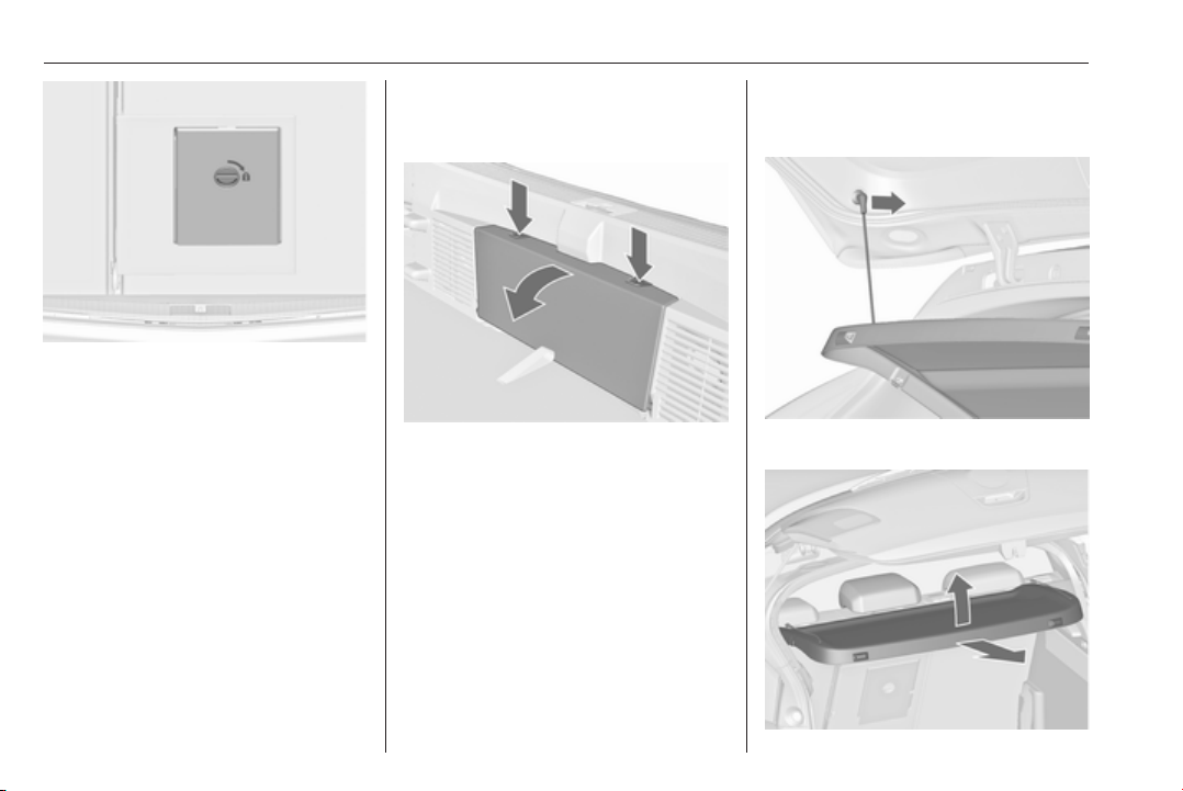
88 Storage
The closed cover can be secured
from the side of the load
compartment. Turn the knob 90°:
knob horizontal : cover secured
from the side of
the passenger
compartment
knob vertical : cover not secured
Rear storage
3-door hatchback
Press both buttons and fold down
cover.
Maximum load: 0.5 kg.
Load compartment cover
Do not place any objects on the cover.
3-door and 5-door hatchback
Removing
Unhook retaining straps from tailgate.
Page 91
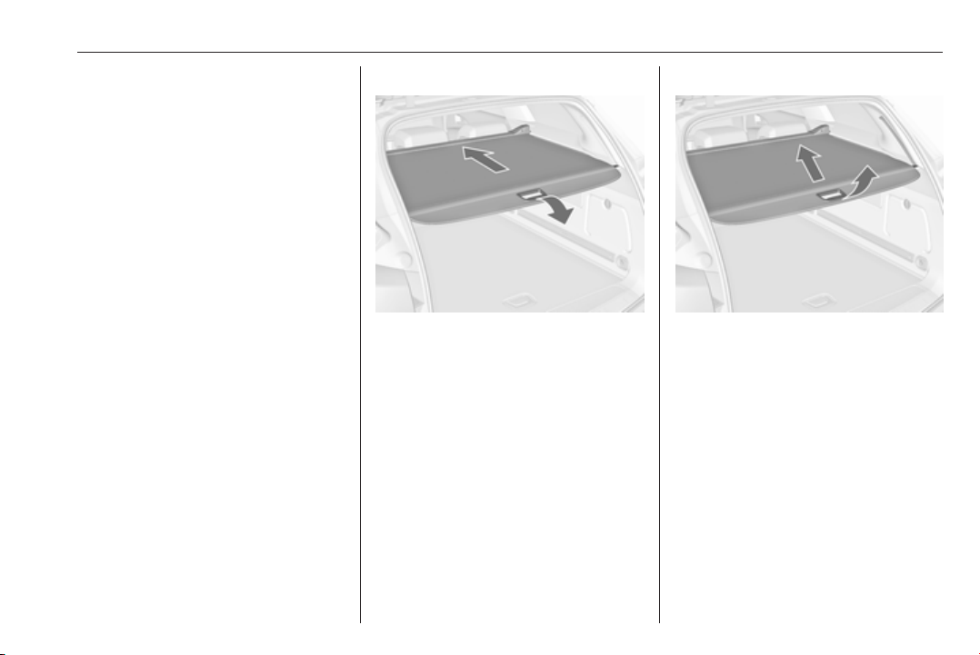
Storage 89
Lift cover at the rear and push it
upwards at the front.
Remove the cover.
If the height adjustable cover is
mounted in the middle or upper
position, the load compartment cover
can be stowed below it.
Height adjustable cover 3 90.
Fitting
Engage cover in side guides and fold
downwards. Attach retaining straps to
tailgate.
Sports tourer
Closing cover
Pull the cover towards the rear using
the handle until it engages in the
sideward retainers.
Opening cover
Pull the handle at the end of the cover
to the rear and downwards. It rolls up
automatically.
Cover in upper position
Push the handle at the end of the
cover downwards. The rear of the
cover is guided upwards
automatically.
Page 92
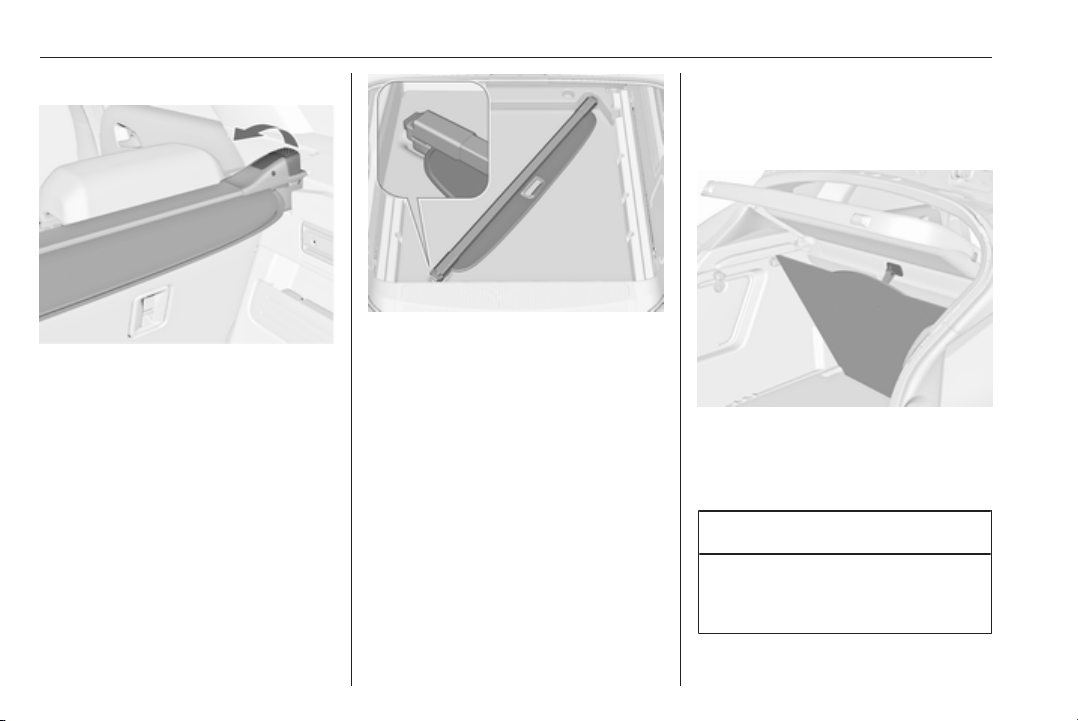
90 Storage
Removing cover
Open the load compartment cover.
Pull the release lever on the right side
up and hold it. Lift the cover first on
the right side and remove from
retainers.
The removed cover can be stored
under the rear floor cover like shown
in the graphic.
Rear floor storage cover 3 90.
Installing cover
Insert the left side of the load
compartment cover in the recess, pull
the release lever up and hold it, insert
the right side of the load compartment
cover and engage.
Rear floor storage cover
Rear floor cover, 3-door hatchback, 5-door hatchback
The rear floor cover can be lifted.
Hinge the loop into the hook on the
lower side of the load compartment
cover.
Caution
Only use the hook for hanging up
the rear floor cover and the height
adjustable cover.
Page 93
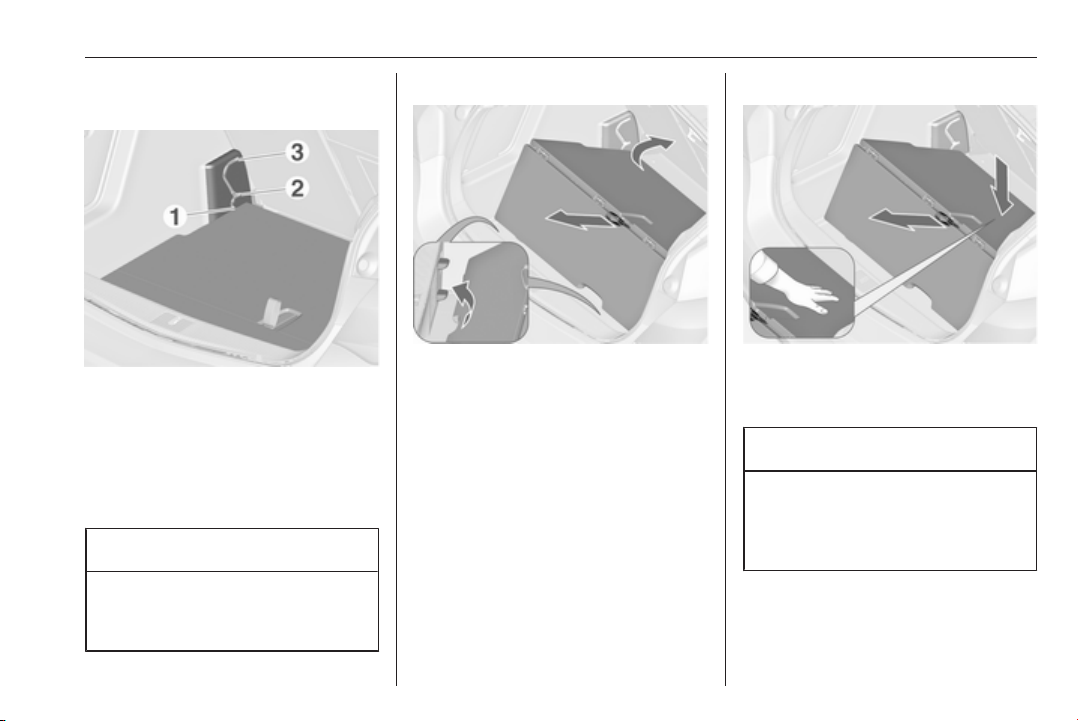
Storage 91
Height adjustable cover, 3-door hatchback, 5-door hatchback
The height adjustable cover can be
mounted in three positions:
● directly above the rear floor cover
(1)
● in a middle position (2)
● in an upper position (3)
Caution
Ensure that the front and rear end
of the height adjustable cover are
attached to the same level.
Lifting
To lift the cover to a higher level, pull
the loop backwards and lift the rear
edge of the cover onto the
corresponding supports.
Lowering
To lower the cover, pull the strap
backwards and push down the front
centre of the cover at the same time.
Caution
Do not lower the height adjustable
cover to position 1 in vehicles
equipped with subwoofer. The
subwoofer could be damaged.
Page 94
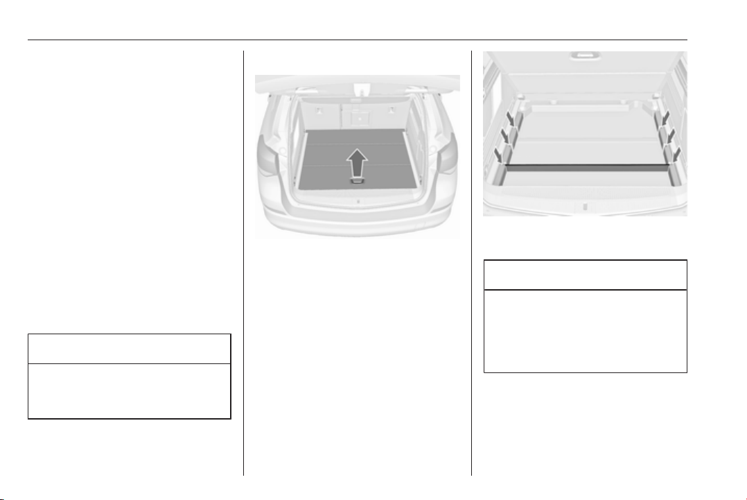
92 Storage
Note
● If mounted in position 2 or 3, the
space between the rear floor
cover and the height adjustable
cover can be used as a stowage
compartment.
● The height adjustable cover can
be lifted and hooked in with the
strap when it is mounted in
position 1 or 2.
● If mounted in position 2, an
almost completely flat load-bay is
created if the rear seat backrests
are folded forwards.
● Opening the side covers (e.g.
when exchanging the rear light
bulbs) is only possible with the
height adjustable cover mounted
in position 1 or 2.
Caution
The height adjustable cover is
able to withstand a load of no more
than 100 kg.
Rear floor cover, Sports tourer
Lift the rear floor cover by pulling the
handle. Fold and place the cover
behind the rear seats.
The storage compartment below the
rear floor cover can be divided by a
bar.
Insert the bar into the recesses at the
sidewalls.
Caution
Insert the bar into the rearmost
recess when transporting heavy
objects in the load compartment.
Otherwise the rear floor cover may
be damaged.
Page 95
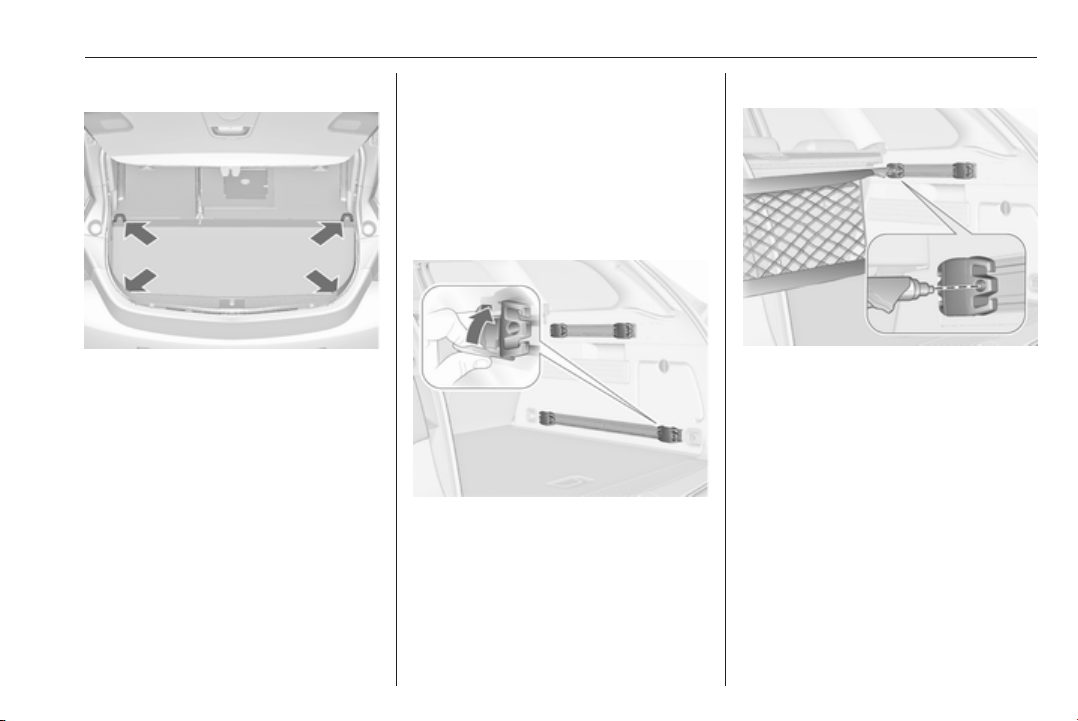
Storage 93
Lashing eyes
The lashing eyes are designed to
secure items against slippage, e.g.
using lashing straps or luggage net.
The lashing eyes are only accessible
if the rear floor storage cover is in the
lower position 3 90.
Cargo management system
The FlexOrganizer is a flexible
system for dividing up the load
compartment.
The system consists of:
● adapters
● mesh pockets
● hooks
● service box
● strap set
The components are fitted in rails on
both side panels using adapters and
hooks.
Installation of adapters in the rails
Fold open the handle plate, insert the
adapter into the upper and lower
groove of the rail and move to the
required position. Turn the handle
plate upwards to lock the adapter. To
remove, turn the handle plate down
and move out of the rail.
Variable partition net
Insert adapters into the required
position in the rails. Stick together the
halves of the net rods.
To install, push rods together a little
and insert into the relevant openings
in the adapters.
To remove, press the net rods
together and remove from the
adapters.
Page 96
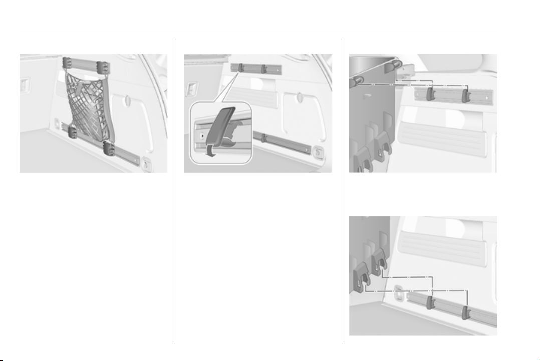
94 Storage
Net pocket
Insert adapters into the required
position in the rails. The net pocket
can be suspended from the adapters.
Installation of hooks in the rails
Insert the hook in the desired position
first in the upper groove of the rail and
then press in the lower groove. To
remove, first pull out of the upper
groove.
Service box
Install two hooks in the upper rail.
Insert the upper brackets of the box
from above into the hooks.
Page 97
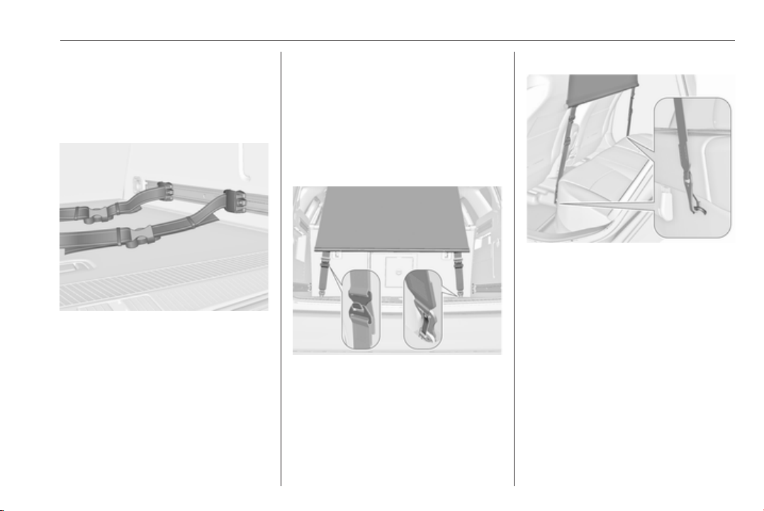
Storage 95
Alternatively install both hooks in the
lower rail. Plug in the lower brackets
of the box from above into the lower
hooks.
Strap set
Insert the adapters of the strap set in
a rail. Make sure that the belt is not
twisted.
The strap set has two locks to open.
The belt can be tightened.
Safety net
The safety net is available on the
Sports tourer and can be installed
behind the rear seats or, if the rear
seat backrests are folded and the
seat cushions raised, behind the front
seats.
Passengers must not be transported
behind the safety net.
Installation
Behind the rear seats
Attach lower hook with opening facing
backward to eye in the right and left
of the floor. Adjust strap length on
safety net by attaching the upper
hook to the eyes of the strap. Keep
strap under tension while proceeding
with installation of rod.
Behind the front seats
Attach strap to eyes underneath the
rear seat cushion.
Fold backrests forward.
To get a flat load-bay, first fold seat
cushion before attaching the safety
net. Move front seats forward to ease
tension if necessary.
Page 98
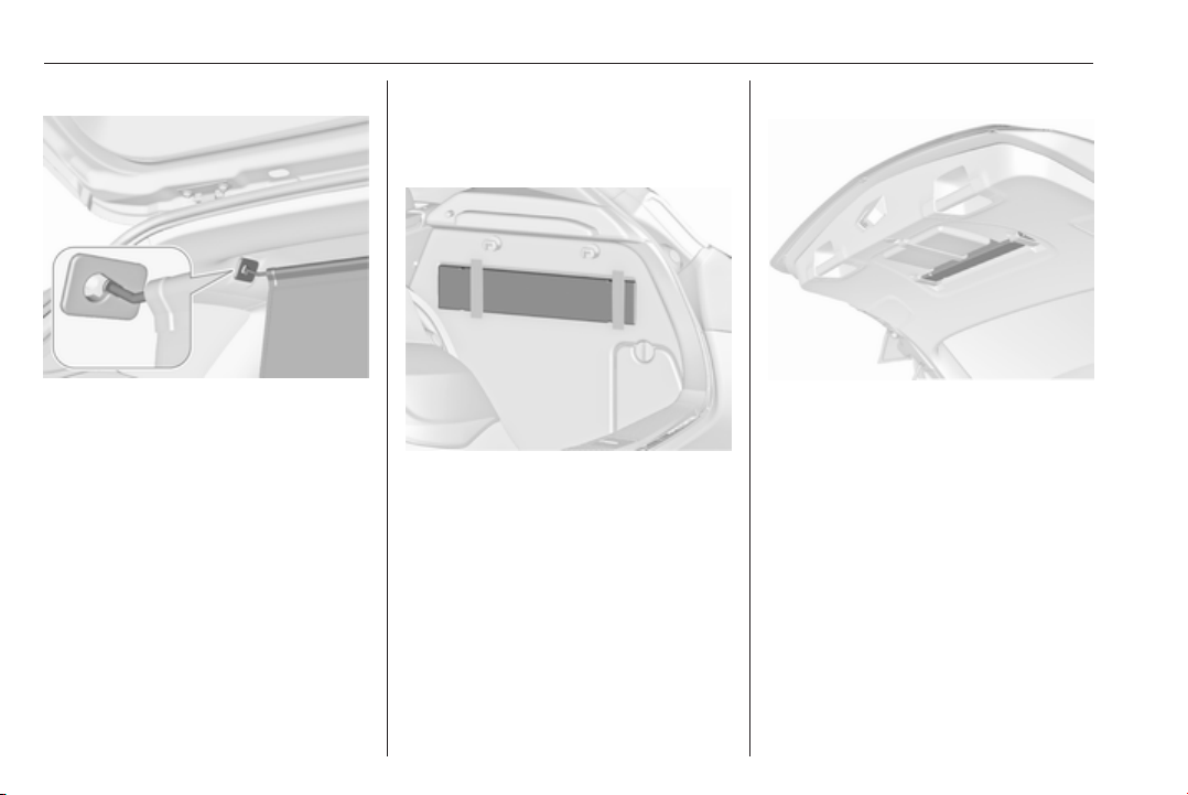
96 Storage
Installation of the rod
There are two installation openings in
the roof frame: suspend and engage
rod of net at one side, compress rod
and suspend and engage at other
side.
Load compartment 3 84.
Removal
Unhook the safety net rods from the
brackets in the roof frame. Detach
straps from the eyes. Roll up the net
and secure with a strap.
The removed safety net can be stored
under the rear floor cover 3 90.
Warning triangle
3-door hatchback, 5-door hatchback
Stow the warning triangle in the space
behind the strap on the right side of
the load compartment.
Sports tourer
Fold down straps. Stow the warning
triangle in the space behind the straps
on the inside of the tailgate.
Page 99
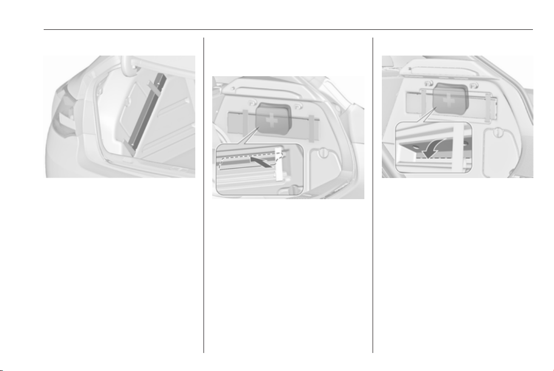
Storage 97
4-door notchback
Stow the warning triangle in the
recess on the left side of the load
compartment.
First aid kit
5-door hatchback
Stow the first aid kit in the stowage
compartment behind the warning
triangle.
Before first use, press in the interior
trim at the top and at the sides of the
perforation. Then fold the trim
outward to gain access to the
stowage compartment.
3-door hatchback
Stow the first aid kit in the stowage
compartment behind the warning
triangle.
Use the recesses to fold down the
cover.
Depending on the equipment, the first
aid kit can be stored in the rear
storage 3 88.
Page 100
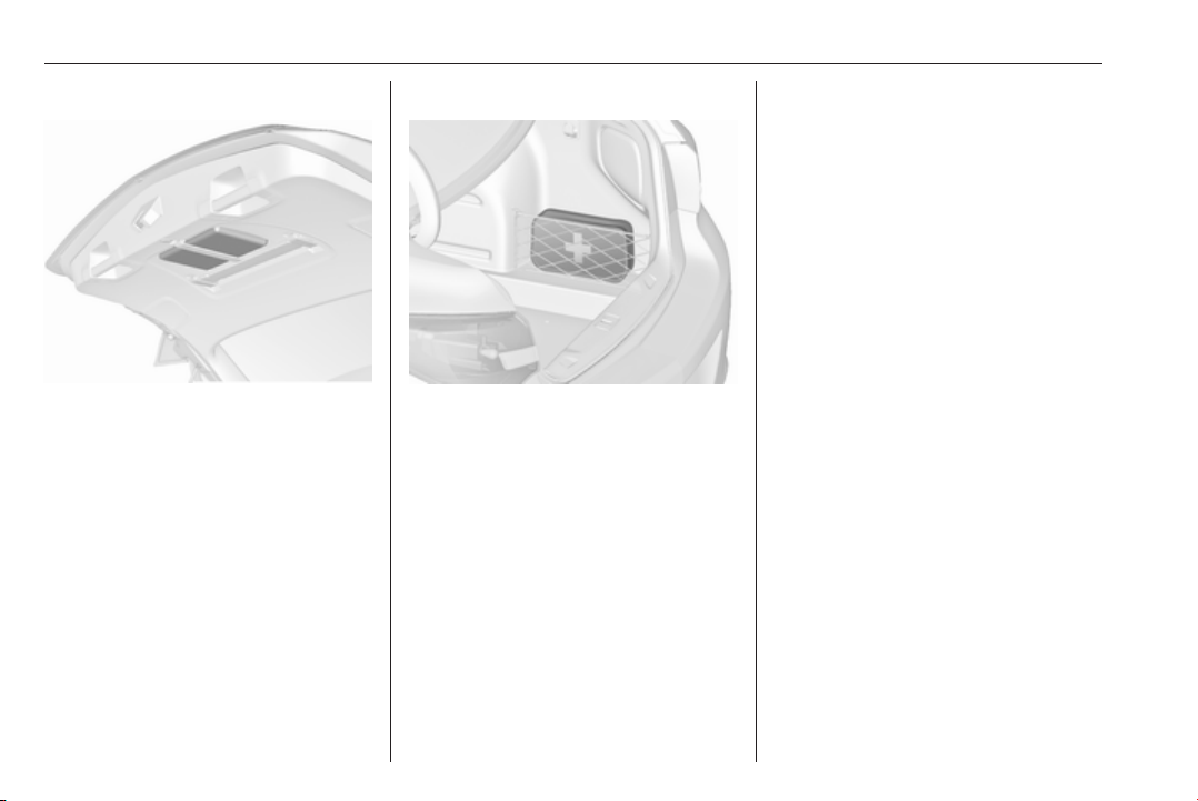
98 Storage
Sports tourer
Fold down strap. Stow the first aid kit
in the space behind a strap on the
inside of the tailgate.
4-door notchback
Stow the first aid kit in the space
behind the mesh net on the right side
of the load compartment.
Roof rack system
Roof rack
For safety reasons and to avoid
damage to the roof, the vehicle
approved roof rack system is
recommended. For further
information contact your workshop.
Follow the installation instructions
and remove the roof rack when not in
use.
Mounting roof rack
Detach the cover from each mounting
point by using a coin.
 Loading...