


 Loading...
Cat. No. I01E-EN-01
USER'S MANUAL
Programmable Controller
Option Board
Models 3G3MV-P10CDT-E
and 3G3MV-P10CDT3-E
(For SYSDRIVE 3G3MV Multi-function Compact Inverters)
3G3MV-P10CDT PLC Option Unit
User’s Manual
Revised June 2003

Notice:
OMRON products are manufactured for use according to proper procedures by a qualified operator and only for the purposes described in this manual.
The following conventions are used to indicate and classify precautions in this manual. Always consult the information provided with them. Failure to heed precautions can result in injury to people or damage to the product.
DANGER |
Indicates an imminently hazardous situation which, if not avoided, will result in death or |
|
serious injury. |
WARNING |
Indicates a potentially hazardous situation which, if not avoided, could result in death or |
|
serious injury. |
Caution |
Indicates a potentially hazardous situation which, if not avoided, may result in minor or |
|
moderate injury, or property damage. |
OMRON Product References
All OMRON products are capitalised in this manual. The word “Unit” is also capitalised when it refers to an OMRON product, regardless of whether or not it appears in the proper name of the product.
The abbreviation “Ch,” which appears in some displays and on some OMRON products, often means “word” and is abbreviated “Wd” in documentation in this sense.
The abbreviation “PLC” means Programmable Controller and is not used as an abbreviation for anything else.
Visual Aids
The following headings appear in the left column of the manual to help you locate different types of information.
Note Indicates information of particular interest for efficient and convenient operation of the product.
1, 2, 3… 1. Indicates lists of one sort or another, such as procedures, checklists, etc.
OMRON, 2003
All rights reserved. No part of this publication may be reproduced, stored in a retrieval system, or transmitted, in any form, or by any means, mechanical, electronic, photocopying, recording, or otherwise, without the prior written permission of OMRON.
No patent liability is assumed with respect to the use of the information contained herein. Moreover, because OMRON is constantly striving to improve its high-quality products, the information contained in this manual is subject to change without notice. Every precaution has been taken in the preparation of this manual. Nevertheless, OMRON assumes no responsibility for errors or omissions. Neither is any liability assumed for damages resulting from the use of the information contained in this publication.
iv
TABLE OF CONTENTS
PRECAUTIONS ...................................................................................... |
viii |
|
1 |
Intended Audience.................................................................................................................................................... |
ix |
2 |
General Precautions.................................................................................................................................................. |
ix |
3 |
Safety Precautions ...................................................................................................................................................... |
x |
4 Maintenance and Inspection Precautions ................................................................................................................. |
xi |
|
5 Operation and Adjustment Precautions.................................................................................................................... |
xi |
|
6 |
Wiring Precautions.................................................................................................................................................. |
xii |
7 |
Application Precautions .......................................................................................................................................... |
xii |
8 |
EC Directives ......................................................................................................................................................... |
xiv |
SECTION 1 |
|
|
INTRODUCTION ...................................................................................... |
1 |
|
1-1 3G3MV-P10CDT Features and Functions ............................................................................................................. |
2 |
|
1-2 |
System Configurations ........................................................................................................................................... |
5 |
1-3 3G3MV-P10CDT Structure and Operation............................................................................................................ |
6 |
|
1-4 Comparison with the CPM2C-S ........................................................................................................................... |
10 |
|
1-5 |
Preparation for Operation ..................................................................................................................................... |
16 |
SECTION 2 |
|
|
UNIT COMPONENTS AND SPECIFICATIONS ................................ |
17 |
|
2-1 |
Specifications ....................................................................................................................................................... |
18 |
2-2 |
Unit Components.................................................................................................................................................. |
26 |
SECTION 3 |
|
|
INSTALLATION AND WIRING ........................................................... |
31 |
|
3-1 |
Installation ............................................................................................................................................................ |
32 |
3-2 |
Wiring................................................................................................................................................................... |
35 |
3-3 |
Connecting I/O Devices ....................................................................................................................................... |
35 |
3-4 |
Wiring Communication Cables ............................................................................................................................ |
37 |
3-5 |
Programming Device Connections....................................................................................................................... |
37 |
SECTION 4 |
|
|
COMMUNICATION, COUNTER AND PULSE .................................. |
38 |
|
4-1 |
PLC-setup Communication .................................................................................................................................. |
39 |
4-2 |
High-speed Counters ............................................................................................................................................ |
42 |
4-3 Input Interrupts In Counter Mode......................................................................................................................... |
45 |
|
4-4 |
Pulse Output Functions......................................................................................................................................... |
48 |
SECTION 5 |
|
|
INVERTER INTERFACE....................................................................... |
56 |
|
5-1 |
Inverter interface .................................................................................................................................................. |
57 |
5-2 |
I/O Allocation IR.................................................................................................................................................. |
57 |
5-3 |
I/O Allocation DM ............................................................................................................................................... |
60 |
5-4 |
Transfer command................................................................................................................................................ |
61 |
APPENDIX A |
|
|
INSTRUCTIONS ...................................................................................... |
69 |
|
v
APPENDIX B |
|
|
EXAMPLE PROGRAMS......................................................................... |
71 |
|
B-1 |
Basic RUN template program ............................................................................................................................. |
71 |
B-2 |
Basic Writing Parameter template program ........................................................................................................ |
71 |
B-3 |
Basic Read Parameter template program ............................................................................................................ |
76 |
B-4 |
Basic Positioning template program ................................................................................................................... |
79 |
REVISION HISTORY.............................................................................. |
97 |
|
vi

About this Manual:
The 3G3MV-P10CDT is a high-speed Programmable Controller (PLC) with a build-in 3G3MV Inverter interface. There are two manuals describing the setup and operation of the 3G3MV-P10CDT: The
3G3MV-P10CDT Operation Manual (this manual) and the CPM1/ CPM1A/CPM2A/CPM2C/SRM1(-V2) Programming Manual (W353). (The CPM1/CPM1A/CPM2A/ CPM2C/SRM1(-V2) Programming Manual is referred to as simply the Programming Manual in this manual.) This manual describes the system configuration and installation of the 3G3MV-P10CDT and provides a basic explanation of operating procedures for the Programming Consoles. Read this manual first to acquaint yourself with the 3G3MVP10CDT.
Refer to the SYSDRIVE 3G3MV Multi-function Compact Inverter User’s Manual for descriptions of the specifications and installation of the 3G3MV Inverters.
The SYSMAC Support Software Operation Manuals: Basics and C-series PLCs (W247 and W248) provide descriptions of SSS operations for the 3G3MV-P10CDT and other SYSMAC C-series PLCs. The SYS-MAC-CPT Support Software Quick Start Guide (W332) and User Manual (W333) provide descriptions of ladder diagram operations in the Windows environment. The CX-Programmer User Manual (W361) and the CX-Server User Manual (W362) provide details of operations for the WS02- CXPC1-E CX-Programmer.
Please read this manual carefully and be sure you understand the information provided before attempting to install and operate the 3G3MV-P10CDT.
Section 1 describes the special features and functions of the 3G3MV-P10CDT, shows the possible system configurations, and outlines the steps required before operation. Read this section first when using the 3G3MV-P10CDT for the first time.
Section 2 provides the technical specifications of the 3G3MV-P10CDT and describes the main components of these Units.
Section 3 provides information on installing and wiring a 3G3MV-P10CDT. Be sure to follow the directions and precautions in this section when installing the 3G3MV-P10CDT in a panel or cabinet, wiring the power supply, or wiring I/O.
Section 4 describes the PLC setup for the communication ports, the counter and pulse-output functionality
Section 5 explains the interface with the 3G3MV Inverter
Appendix A provides the instruction set.
Appendix B provides examples.
WARNING Failure to read and understand the information provided in this manual may result in personal injury or death, damage to the product, or product failure. Please read each section in its entirety, and be sure you understand the information provided in the section and related sections before attempting any of the procedures or operations given.
vii
PRECAUTIONS
This section provides general precautions for using the Programmable Controller (PLC) and related devices.
The information contained in this section is important for the safe and reliable application of the Programmable Controller. You must read this section and understand the information contained before attempting to set up or operate a PLC system.
1 |
Intended Audience.................................................................................................................................................... |
ix |
2 |
General Precautions.................................................................................................................................................. |
ix |
3 |
Safety Precautions ..................................................................................................................................................... |
x |
4 |
Maintenance and Inspection Precautions.................................................................................................................. |
xi |
5 |
Operation and Adjustment Precautions .................................................................................................................... |
xi |
6 |
Wiring Precautions .................................................................................................................................................. |
xii |
7 |
Application Precautions........................................................................................................................................... |
xii |
8 |
EC Directives.......................................................................................................................................................... |
xiv |
viii

PRECAUTIONS
1 Intended Audience
This manual is intended for the following personnel, who must also have knowledge of electrical systems (an electrical engineer or the equivalent).
•Personnel in charge of installing FA systems.
•Personnel in charge of designing FA systems.
•Personnel in charge of managing FA systems and facilities.
2 General Precautions
The user must operate the product according to the performance specifications described in the operation manuals.
Before using the product under conditions which are not described in the manual or applying the product to nuclear control systems, railroad systems, aviation systems, vehicles, combustion systems, medical equipment, amusement machines, safety equipment, and other systems, machines and equipment that may have a serious influence on lives and property if used improperly, consult your OMRON representative.
Make sure that the ratings and performance characteristics of the product are sufficient for the systems, machines, and equipment, and be sure to provide the systems, machines, and equipment with double safety mechanisms.
This manual provides information for installing and operating OMRON 3G3MV Inverter PLC Option Units. Be sure to read this manual before operation and keep this manual close at hand for reference during operation.
 WARNING It is extremely important that a PLC, and all PLC Units, be used for the specified purpose and under the specified conditions, especially in applications that can directly or indirectly affect human life. You must consult with your OMRON representative before applying a PLC system to the above mentioned applications.
Observe the following precautions when using the SYSDRIVE Inverters and peripheral devices.
This manual may include illustrations of the product with protective covers removed in order to describe the components of the product in detail. Make sure that these protective covers are on the product before use.
Consult your OMRON representative when using the product after a long period of storage.
 WARNING Do not touch the inside of the Inverter. Doing so may result in electrical shock.
 WARNING Operation, maintenance, or inspection must be performed after turning OFF the power supply, confirming that the CHARGE indicator (or status indicators) are OFF, and after waiting for the time specified on the front cover. Not doing so may result in electrical shock.
 WARNING Do not damage, pull on, apply stress to, place heavy objects on, or pinch the cables. Doing so may result in electrical shock.
 WARNING Do not touch the rotating parts of the motor under operation. Doing so may
ix

PRECAUTIONS
result in injury.
 WARNING Do not modify the product. Doing so may result in injury or damage to the product.
Caution Do not store, install, or operate the product in the following places. Doing so may result in electrical shock, fire or damage to the product.
•Locations subject to direct sunlight.
•Locations subject to temperatures or humidity outside the range specified in the specifications.
•Locations subject to condensation as the result of severe changes in temperature.
•Locations subject to corrosive or flammable gases.
•Locations subject to exposure to combustibles.
•Locations subject to dust (especially iron dust) or salts.
•Locations subject to exposure to water, oil, or chemicals.
•Locations subject to shock or vibration.
Caution Do not touch the Inverter radiator, regenerative resistor, or Servomotor while the power is being supplied or soon after the power is turned OFF. Doing so may result in a skin burn due to the hot surface.
Caution Do not conduct a dielectric strength test on any part of the Inverter. Doing so may result in damage to the product or malfunction.
Caution Take appropriate and sufficient countermeasures when installing systems in the following locations. Not doing so may result in equipment damage.
•Locations subject to static electricity or other forms of noise.
•Locations subject to strong electromagnetic fields and magnetic fields.
•Locations subject to possible exposure to radioactivity.
•Locations close to power supplies.
3 Safety Precautions
 WARNING The Unit refreshes I/O even when the program is stopped (i.e., even in PROGRAM mode). Confirm safety thoroughly in advance before changing the status of any part of memory allocated to I/O or the Inverter. Any changes to the data allocated to any of these may result in unexpected operation of the loads connected to the Unit or Inverter. Any of the following operation may result in changes to memory status.
•Transferring I/O memory data from a Programming Device to the Unit.
•Changing present values in memory with a Programming Device.
•Force-setting/-resetting bits with a Programming Device.
•Transferring I/O memory from a host computer or from another PLC on a network.
 WARNING Do not attempt to take any Unit apart while the power is being supplied. Doing so may result in electric shock.
x

PRECAUTIONS
 WARNING Do not touch any of the terminals or terminal blocks while the power is being supplied. Doing so may result in electric shock.
 WARNING Do not attempt to disassemble, repair, or modify any Units. Any attempt to do so may result in malfunction, fire, or electric shock.
Caution Execute online edit only after confirming that no adverse effects will be caused by extending the cycle time. Otherwise, the input signals may not be readable.
Caution Confirm safety at the destination node before transferring a program to another node or changing contents of the I/O memory area. Doing either of these without confirming safety may result in injury.
4 Maintenance and Inspection Precautions
 WARNING Do not touch the Inverter terminals while the power is being supplied.
 WARNING Maintenance or inspection must be performed only after turning OFF the power supply, confirming that the CHARGE indicator (or status indicators) is turned OFF, and after waiting for the time specified on the front cover. Not doing so may result in electrical shock.
 WARNING Maintenance, inspection, or parts replacement must be performed by authorized personnel. Not doing so may result in electrical shock or injury.
 WARNING Do not attempt to take the Unit apart or repair. Doing either of these may result in electrical shock or injury.
Caution Carefully handle the Inverter because it uses semiconductor elements. Careless handling may result in malfunction.
Caution Do not change wiring, disconnect connectors or Operator, or replace fans while power is being supplied. Doing so may result in injury or malfunction.
Caution Be sure to wire correctly and securely. Not doing so may result in injury or damage to the product.
5 Operation and Adjustment Precautions
 WARNING Turn ON the input power supply only after mounting the front cover, terminal covers, bottom cover, Operator, and optional items. Not doing so may result in electrical shock.
 WARNING Do not remove the front cover, terminal covers, bottom cover, Operator, or optional items while the power is being supplied. Not doing so may result in electrical shock.
 WARNING Do not operate the Operator or switches with wet hands. Doing so may result in electrical shock.
xi
PRECAUTIONS
 WARNING Do not touch the inside of the Inverter. Doing so may result in electrical shock.
 WARNING Provide a separate emergency stop switch because the STOP Key on the Operator is valid only when function settings are performed. Not doing so may result in injury.
6 Wiring Precautions
 WARNING Wiring must be performed only after confirming that the power supply has been turned OFF. Not doing so may result in electrical shock.
 WARNING Wiring must be performed by authorized personnel. Not doing so may result in electrical shock or fire.
7 Application Precautions
Observe the following precautions when using the PLC Unit.
 WARNING Failure to abide by the following precautions could lead to serious or possibly fatal injury. Always heed these precautions.
•Always ground the system with 100 Ω or less when installing the system, to protect against electrical shock.
•Always turn off the power supply to the PLC before attempting any of the following. Performing any of the following with the power supply turned on may lead to electrical shock:
•Assembling any devices or racks.
•Connecting or disconnecting any connectors, cables or wiring.
•Setting DIP switches or rotary switches.
 WARNING Failure to abide by the following precautions could lead to faulty operation of the PLC or the system, or could damage the PLC or PLC Units. Always heed these precautions.
•Fail-safe measures must be taken by the customer to ensure safety in the event of incorrect, missing, or abnormal signals caused by broken signal lines, momentary power interruptions, or other causes.
•Interlock circuits, limit circuits, and similar safety measures in external circuits (i.e., not in the Programmable Controller) must be provided by the customer.
•Use the Units only with the power supplies and voltages specified in the operation manuals. Other power supplies and voltages may damage the Units.
•Take appropriate measures to ensure that the specified power with the rated voltage and frequency is supplied. Be particularly careful in places where the power supply is unstable. An incorrect power supply may result in malfunction.
•Install external breakers and take other safety measures against shortcircuiting in external wiring. Insufficient safety measures against shortcircuiting may result in burning.
•Do not apply voltages exceeding the rated input voltage to Input Units. The
xii

PRECAUTIONS
Input Units may be destroyed.
•Do not apply voltages exceeding the maximum switching capacity to Output Units. The Output Units may be destroyed.
Caution • Install the Units properly as specified in the operation manuals. Improper installation of the Units may result in malfunction.
•Wire all connections correctly. Double-check all wiring and switch settings before turning on the power supply. Incorrect wiring may result in burning.
•Mount Units only after checking terminal blocks and connectors completely.
•Be sure that the terminal blocks, Memory Units, expansion cables, and other items with locking devices are properly locked into place. Improper locking may result in malfunction.
•Check switch settings, the contents of the DM Area, and other preparations before starting operation. Starting operation without the proper settings or data may result in an unexpected operation.
•Check the user program for proper execution before actually running it on the Unit. Not checking the program may result in an unexpected operation.
•Confirm that no adverse effect will occur in the system before attempting any of the following. Not doing so may result in an unexpected operation.
•Changing the operating mode of the PLC.
•Force-setting/force-resetting any bit in memory.
•Changing the present value of any word or any set value in memory.
•Resume operation with a new CPU Unit only after transferring the contents of the DM Area, HR Area, and other data required for resuming operation to the new Unit. Not doing so may result in an unexpected operation.
•Do not pull on the cables or bend the cables beyond their natural limit. Doing either of these may break the cables.
•Do not place objects on top of the cables or other wiring lines. Doing so may break the cables.
•Before touching a Unit, be sure to first touch a grounded metallic object in order to discharge any static built-up. Not doing so may result in malfunction or damage.
•Do not touch circuit boards or the components mounted to them with your bare hands. There are sharp leads and other parts on the boards that may cause injury if handled improperly.
•Do not attempt to take any Units apart, to repair any Units, or to modify any Units in any way.
xiii

PRECAUTIONS
8 EC Directives
8-1 Applicable Directives
•EMC Directives
•Low Voltage Directive
8-2 Concepts
EMC Directives
OMRON devices that comply with EC Directives also conform to the related EMC standards so that they can be more easily built into other devices or the overall machine. The actual products have been checked for conformity to EMC standards (see the following note). Whether the products conform to the standards in the system used by the customer, however, must be checked by the customer.
EMC-related performance of the OMRON devices that comply with EC Directives will vary depending on the configuration, wiring, and other conditions of the equipment or control panel on which the OMRON devices are installed. The customer must, therefore, perform the final check to confirm that devices and the overall machine conform to EMC standards.
Note Applicable EMC (Electromagnetic Compatibility) standards are as follows:
EMS (Electromagnetic Susceptibility): EN61800-3
EMI (Electromagnetic Interference): |
EN50081-2/EN55011 |
(Radiated emission: 10-m regulations)
Low Voltage Directive
Safety standard: EN50178: 1997
8-3 Conformance to EC Directives
The 3G3MV series products comply with EC Directives. To ensure that the machine or device in which the PLC is used complies with EC Directives, the PLC must be installed as follows:
1, 2, 3... 1. The PLC must be installed within a control panel.
2.You must use reinforced insulation or double insulation for the DC power supplies used for the communications power supply and I/O power supplies.
3.OMRON PLCs complying with EC Directives also conform to the Common Emission Standard (EN50081-2). Radiated emission characteristics (10-m regulations) may vary depending on the configuration of the control panel used, other devices connected to the control panel, wiring, and other conditions. You must therefore confirm that the overall machine or equipment complies with EC Directives.
xiv
SECTION 1 Introduction
This section describes the special features and functions of the 3G3MV-P10CDT, shows the possible system configurations, and outlines the steps required before operation. Read this section first when using the 3G3MV-P10CDT for the first time. Refer to the CPM1/CPM1A/CPM2A/CPM2C/SRM1(-V2) Programming Manual (W353) for details on programming operations.
1-1 3G3MV-P10CDT Features and Functions ............................................................................................................. |
2 |
||
|
1-1-1 |
3G3MV-P10CDT Features ............................................................................................................................. |
2 |
|
1-1-2 Overview of 3G3MV-P10CDT Functions ....................................................................................................... |
4 |
|
1-2 |
System Configurations ........................................................................................................................................... |
5 |
|
|
1-2-1 |
Unit types ........................................................................................................................................................ |
5 |
1-3 |
3G3MV-P10CDT Structure and Operation............................................................................................................ |
6 |
|
|
1-3-1 |
3G3MV-P10CDT Structure............................................................................................................................. |
6 |
|
1-3-2 |
Operating Modes............................................................................................................................................. |
7 |
|
1-3-3 Operating Mode at Startup ............................................................................................................................. |
8 |
|
|
1-3-4 Cyclic Operation and Interrupts ..................................................................................................................... |
9 |
|
1-4 |
Comparison with the CPM2C-S ........................................................................................................................... |
10 |
|
1-5 |
Preparation for Operation..................................................................................................................................... |
16 |
|
Introduction |
SECTION 1 |
1-1 3G3MV-P10CDT Features and Functions
1-1-1 3G3MV-P10CDT Features
The 3G3MV-P10CDT PLC Option Units are compact CPM2C PLCs that have been equipped with a 3G3MV-Inverter interface. The 3G3MV-P10CDT incorporates a variety of special features just like the CPM2C, including synchronized pulse control, interrupt inputs, pulse outputs, and a clock function.
•The Inverter interface reduces wiring, and saves space. Instead of using a CPM2C with CIF11 to communicate to an 3G3MV-Inverter, the P10CDT communicates directly to the Inverter without the overhead.
•The 3G3MV-P10CDT itself can handle a wide range of machine control applications. In addition, the 3G3MV-P10CDT is capable of communications with devices such as personal computers and OMRON Programmable Terminals so it is ideal to use to expand or upgrade existing systems.
•The 3G3MV-P10CDT CPU Unit has a total of 10 I/O points: 6 inputs, 3 transistor outputs and 1 relay output.
•The communications port can be used simultaneously as two ports: Peripheral and RS-232C. The peripheral port supports Programming Devices, Host Link, and no-protocol communications. The RS-232C port supports Host Link, no-protocol (serial), 1:1 PLC Link, and 1:1 NT Link communications.
•Included is also an RS-422/485 interface (not all models) which allows for a cheap connection to other 3G3MV-P10CDT’s, other Inverters, NTterminals, etc.
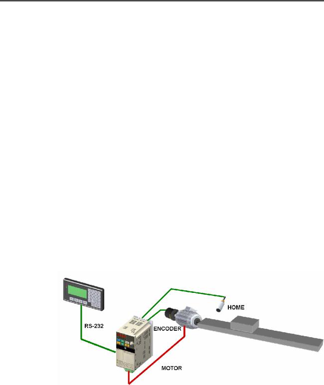
Example System Configuration
A basic standalone application with HMI:
2
Introduction |
SECTION 1 |
|
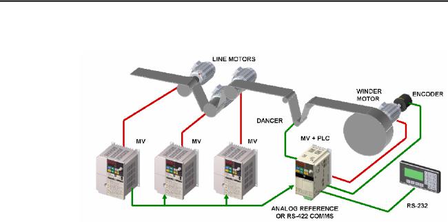
A typical winder application: |
The 3G3MV and PLC Option Unit take care of diameter calculation, dancer PID, user input, etc. The other simply run in speed control. This type of application uses both RS-232C and RS-422 communication.
Loss of Inverter functionality
Whenever the 3G3MV-P10CDT is attached to a 3G3MV Inverter, the following functionality of the Inverter is lost:
• Modbus communication through the RS-422 interface of the Inverter is disabled. The Modbus communication through the RJ-45 connector is still available.
Inverter-interface restriction
The following resources have limited control:
•Only one analog input can be read directly. The other input can be read by using the Transfer command in combination with PID with feedback.
•The analog outputs cannot be controlled by the 3G3MV-P10CDT
Note Minimum Inverter firmware version requirement: 24
3

Introduction SECTION 1
1-1-2 Overview of 3G3MV-P10CDT Functions
Main function |
|
Variations/Details |
|
Inverter interface |
Direct interface with 3G3MV Inverter through |
|
|
|
• |
IR-memory |
|
|
• |
DM-memory |
|
|
• |
Transfer command |
|
Interrupts |
Interrupt inputs |
|
|
|
2 inputs |
|
|
|
|
Response time: 50 s |
|
|
Interval timer interrupts |
Scheduled interrupts |
|
|
1 input |
|
|
|
|
Set value: 0.5 to 319,968 ms |
One-shot interrupt |
|
|
Precision: 0.1 ms |
|
High-speed counters |
High-speed counter |
No interrupt |
|
|
1 input, see note 1. |
Count-check interrupt |
|
|
|
Differential phase mode (5 kHz) |
(An interrupt can be generated when the |
|
|
Pulse plus direction input mode (20 kHz) |
count equals the set value or the count |
|
|
Up/down input mode (20 kHz) |
lies within a preset range.) |
|
|
Increment mode (20 kHz) |
|
|
Interrupt inputs (counter mode) |
No interrupt |
|
|
2 inputs |
|
|
|
Count-up interrupt |
||
|
|
Incrementing counter (2 kHz) |
|
|
|
|
|
|
|
Decrementing counter (2 kHz) |
|
Pulse outputs |
• |
2 outputs: |
|
|
|
Single-phase pulse output without acceleration/deceleration (See note 2.) |
|
|
|
10 Hz to 10 kHz |
|
|
• |
2 outputs: |
|
|
|
Variable duty ratio pulse output (See note 2.) |
|
|
|
0.1 to 999.9 Hz, duty ratio 0 to 100% |
|
|
• |
1 output: |
|
|
|
Pulse output with trapezoidal acceleration/deceleration (See note 2.) |
|
|
|
Pulse plus direction output, up/down pulse output, 10 Hz to 10 kHz |
|
Synchronized pulse |
1 point, see notes 1 and 2. |
|
|
control |
|
Input frequency range: 10 to 500 Hz, 20 Hz to 1 kHz, or 300 Hz to 20 kHz |
|
|
|
Output frequency range: 10 Hz to 10 kHz |
|
Quick-response input |
2 inputs |
|
|
|
|
Minimum input signal width: 50 s |
|
Input time constant |
Determines the input time constant for all inputs. (Settings: 1, 2, 3, 5, 10, 20, 40, or 80 ms) |
||
|
|
||
Calendar/Clock |
Shows the current year, month, day of the week, day of the month, hour, minute, and |
||
|
second. |
|
|
Note 1. This input is shared by the high-speed counter and synchronized pulse control functions.
2.This output is shared by the pulse output and synchronized pulse control functions.
4

Introduction |
SECTION 1 |
1-2 System Configurations
1-2-1 Unit types
3G3MV-P10CDT Units
Item |
3G3MV-P10CDT-E |
3G3MV-P10CDT3-E |
PLC core |
CPM2C-S |
CPM2C-S |
|
|
|
Inputs |
6 24 VDC inputs |
6 24 VDC inputs |
|
|
|
Outputs |
3 sinking transistor outputs |
3 sinking transistor outputs |
|
1 relay output |
1 relay output |
Peripheral port |
Yes |
Yes |
RS-232C port |
Yes |
Yes |
RS-422/485 port |
No |
Yes |
Calendar/Clock |
No |
Yes |
Memory backup |
Flash memory and capacitor |
Flash memory and battery |
5
Introduction |
SECTION 1 |
1-3 3G3MV-P10CDT Structure and Operation
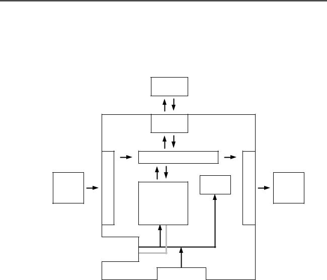
1-3-1 3G3MV-P10CDT Structure
The following diagram shows the internal structure of the Unit.
|
|
3G3MV |
|
|
|
|
|
Inverter |
|
|
|
|
|
Inverter |
|
|
|
|
|
interface |
|
|
|
|
Inputcircuits |
I/O memory |
|
Outputcircuits |
|
External |
Program |
Settings |
External |
||
input |
|
|
PC Setup |
|
output |
devices |
|
|
|
|
devices |
|
Communications |
Settings |
|
|
|
|
|
|
|
|
|
|
ports |
|
|
|
|
|
|
Settings |
|
|
|
|
|
Communications |
|
|
|
|
|
Switches |
|
|
|
I/O Memory |
The program reads and writes data in this memory area during execution. |
|
Part of the I/O memory contains the bits that reflect the status of the PLC’s |
|
inputs and outputs. Parts of the I/O memory are cleared when the power is |
|
turned ON and other parts are retained. |
Program |
This is the program written by the user. The 3G3MV-P10CDT executes the |
|
program cyclically. (Refer to section 1-3-4 Cyclic Operation and Interrupts for |
|
details.) The program can be divided broadly into two parts: the “main pro- |
|
gram” that is executed cyclically and the “interrupt programs” that are exe- |
|
cuted only when the corresponding interrupt is generated. |
PLC Setup |
The PLC Setup contains various startup and operating parameters. The PLC |
|
Setup parameters can be changed from a Programming Device only; they |
|
cannot be changed from the program. |
|
Some parameters are accessed only when PLC’s power supply is turned ON |
|
and others are accessed regularly while the power is ON. It will be necessary |
|
to turn the power OFF and then ON again to enable a new setting if the pa- |
|
rameter is accessed only when the power is turned ON. |
|
Note Refer to 4-1 PLC-setup for details on the PLC Setup. |
Communications |
The Communications Switches determine whether the peripheral port and |
Switches |
RS-232C port connected through the communications port operate with the |
|
standard communications settings or the communications settings in the PLC |
|
Setup. |
Inverter Interface |
The PLC core communicates to the Inverter through IR-, DM-memory, either |
|
by direct mapping or through the Transfer command. |
|
Note Refer to section 5-4 Transfer command for more details. |
6

Introduction |
SECTION 1 |
1-3-2 Operating Modes
3G3MV-P10CDT Units have 3 operating modes: PROGRAM, MONITOR, and RUN.
PROGRAM Mode The program cannot be executed in PROGRAM mode. This mode is used to perform the following operations in preparation for program execution.
•Changing initial/operating parameters such as those in the PLC Setup
•Writing, transferring, or checking the program
•Checking wiring by force-setting and force-resetting I/O bits
Caution The PLC continues to refresh I/O bits even if the PLC is in PROGRAM mode, so devices connected to output points may operate unexpectedly if the corresponding output bit is turned ON by transferring I/O memory or forcesetting output bits from a Programming Device.
MONITOR Mode |
The program is executed in MONITOR mode and the following operations |
|
can be performed from a Programming Device. In general, MONITOR mode |
|
is used to debug the program, test operation, and make adjustments. |
|
• Online editing |
|
• Monitoring I/O memory during operation |
|
• Force-setting/force-resetting I/O bits, changing set values, and changing |
|
present values during operation |
RUN Mode |
The program is executed at normal speed in RUN mode. Operations such as |
|
online editing, force-setting/force-resetting I/O bits, and changing set values/ |
|
present values cannot be performed in RUN mode, but the status of I/O bits |
|
can be monitored. |
7
Introduction |
SECTION 1 |
1-3-3 Operating Mode at Startup
The operating mode of the 3G3MV-P10CDT when the power is turned ON depends upon the setting of pin 2 on the DIP switch on the front of the 3G3MV-P10CDT, the PLC Setup settings in DM 6600, and the Programming Console’s mode switch setting if a Programming Console is connected.
PLC Setup setting |
Operating mode |
||
Word |
Bits |
Setting |
|
|
|
|
|
DM 6600 |
08 to 15 |
00 (Hex) |
See note 1. |
|
|
01 (Hex) |
Startup mode is the same as the operating |
|
|
|
mode before power was interrupted. |
|
|
|
|
|
|
02 (Hex) |
Startup mode is determined by bits 00 to 07. |
|
00 to 07 |
00 (Hex) |
PROGRAM mode |
|
|
01 (Hex) |
MONITOR mode |
|
|
02 (Hex) |
RUN mode |
Note 1. The operating mode at startup depends upon the setting of DIP switch pin 2 and the Programming Device connected to the communications port (peripheral port).
Programming Device |
Pin 2 OFF |
Pin 2 ON |
|
|
|
None |
PROGRAM mode |
RUN mode |
Programming Console |
Operating mode set on the Programming Console’s |
|
|
mode switch |
|
Other device |
PROGRAM mode |
|
The default setting for bits 08 to 15 of DM 6600 is 00. If this default setting is used and pin 2 is OFF, the 3G3MV-P10CDT will automatically start operating in RUN mode when the power is turned ON.
Note 2. If pin 2 is OFF and only an RS-232C cable is connected to the communications port (i.e., there is no peripheral port connection), the 3G3MV-P10CDT will automatically start operating in RUN mode when the power is turned ON. Example Cable Connections:
CS1W-CN118 and XW2Z-200S/500S CS1W-CN118 and XW2Z-200S-V/500S-V
CPM2C-CN111 and XW2Z-200S/500S (no peripheral port connection) CPM2C-CN111 and XW2Z-200S-V/500S-V (no peripheral port connection)
8

Introduction SECTION 1
1-3-4 Cyclic Operation and Interrupts
Basic CPU Operation |
Initialisation processing is performed when the power is turned on. If there |
||
|
are no initialisation errors, the overseeing processes, program execution, I/O |
||
|
refreshing, and communications port servicing are performed repeatedly (cy- |
||
|
clically). |
|
|
|
|
Initial Processing |
|
|
|
|
|
|
|
Inverter interface |
Inverter Interface initial processing |
|
|
initial Processing |
|
|
|
|
|
|
|
|
|
|
|
Common |
|
|
|
processing |
|
|
|
|
|
|
|
Inverter IN |
Inverter Interface status refresh |
|
|
refresh |
|
|
|
|
|
|
|
Program |
|
|
|
execution |
|
|
|
processing |
|
|
|
Cycle time |
|
|
|
calculation |
|
|
|
processing |
|
|
|
|
|
|
|
I/O refesh |
|
|
|
|
|
|
|
Inverter OUT |
Inverter Interface control data refresh |
|
|
refresh |
|
|
|
|
|
|
|
Inverter Modbus |
Inverter Interface Modbus command execution |
|
|
transfer |
When Inverter processing is ended by END refresh timing, a maximum of |
|
|
|
eight data items are read or writen. If the Inverter is currently processing, |
|
|
RS-232C port |
nothing will be done and it will be checked with the next scan. |
|
|
|
|
|
|
service |
|
|
|
|
|
|
|
Peripheral port |
|
|
|
service |
|
|
|
|
|
|
The cycle time can be read from a Programming Device. |
||
|
AR 14 contains the maximum cycle time and AR15 contains the present |
||
|
cycle time in multiples of 0.1 ms. |
||
9

Introduction SECTION 1
1-4 Comparison with the CPM2C-S
|
Item |
|
CPM2C-S |
3G3MV-P10CDT |
|
Instruction set |
Basic instructions |
|
14 |
14 |
|
|
|
|
|
|
|
|
Special instructions |
105 instructions, 185 variations |
105 instructions, 185 variations |
||
|
|
|
|
|
|
Instruction |
Basic instructions |
|
LD: 0.64 s |
LD: 0.64 s |
|
execution times |
Special instructions |
MOV(21): 7.8 s |
MOV(21): 7.8 s |
||
Program capacity |
|
|
|
4,096 words |
4,096 words |
|
|
|
|
|
|
Maximum |
Stand-alone CPU Unit |
10 points |
10 points |
||
number of I/O |
|
|
|
|
|
CPU Unit with Expansion I/O |
362 points max. |
--- |
|||
points |
Units |
|
|
|
|
|
|
|
|
||
Expansion Units |
Maximum number of Units |
A maximum of 3 Units. |
--- |
||
and Expansion |
|
|
|
|
|
Available models |
|
Expansion I/O Units, Analog I/O |
--- |
||
I/O Units |
|
|
|
Unit, Temperature Sensor Unit, |
|
|
|
|
|
and CompoBus/S I/O Link Unit |
|
I/O memory |
Input bits |
|
IR 00000 to IR 00915 |
IR 00000 to IR 00005 |
|
|
|
|
|
|
|
|
Output bits |
|
IR 01000 to IR 01915 |
IR 01000 to IR 01003 |
|
|
|
|
|
|
|
I/O memory |
Work bits |
|
672 bits: |
880 bits: |
|
|
|
|
|
IR 02800 to IR 02915, |
IR 00100 to IR 00915, |
|
|
|
|
IR 03800 to IR 04915, |
IR 01100 to IR 02815, |
|
|
|
|
IR 20000 to IR 22715 |
IR 03000 to IR 04915, |
|
|
|
|
|
IR 22000 to IR 22715 |
|
SR (Special Relay) area |
448 bits: |
448 bits: |
||
|
|
|
|
SR 22800 to SR 25515 |
SR 22800 to SR 25515 |
|
TR (Temporary Relay) area |
8 bits: TR0 to TR7 |
8 bits: TR0 to TR7 |
||
|
HR (Holding Relay) area |
320 bits: |
320 bits: |
||
|
|
|
|
HR 0000 to HR 1915 |
HR 0000 to HR 1915 |
|
|
|
|
|
|
|
AR (Auxiliary Relay) area |
384 bits: |
384 bits: |
||
|
|
|
|
AR 0000 to AR 2315 |
AR 0000 to AR 2315 |
|
LR (Link Relay) area |
256 bits: |
256 bits: |
||
|
|
|
|
LR 0000 to LR 1515 |
LR 0000 to LR 1515 |
|
|
|
|
|
|
|
Timer/Counter area |
256 bits: |
256 bits: |
||
|
|
|
|
TIM/CNT 000 to TIM/CNT 255 |
TIM/CNT 000 to TIM/CNT 255 |
|
DM (Data |
|
Read/write |
2,022 words: |
1,993 words: |
|
Memory) area |
|
area |
DM 0000 to DM 2021 |
DM 0000 to DM 1985 |
|
|
|
|
|
DM 2041 to DM 2047 |
|
|
|
|
|
|
|
|
|
Reserved |
--- |
14 words: |
|
|
|
|
|
DM 1986 to DM 1999 |
|
|
|
Read-only |
456 words: |
456 words: |
|
|
|
area |
DM 6144 to DM 6599 |
DM 6144 to DM 6599 |
|
|
|
PLC Setup |
56 words: |
56 words: |
|
|
|
|
DM 6600 to DM 6655 |
DM 6600 to DM 6655 |
|
|
|
|
|
|
|
Inverter Interface |
|
--- |
288 bits: |
|
|
|
|
|
|
IR 20000 to IR 21715 |
|
|
|
|
|
19 words: |
|
|
|
|
|
DM 2022 to DM 2040 |
|
|
|
|
|
|
10

Introduction |
|
|
|
SECTION 1 |
|
|
|
|
|
|
|
Item |
CPM2C-S |
3G3MV-P10CDT |
Memory backup |
Program area, read-only DM |
Flash memory backup |
Flash memory backup |
|
|
area (including PLC Setup) |
|
|
|
|
Read/write DM area, HR |
Internal battery backup (2-year |
Unit with clock: |
|
|
area, AR area, and counters |
life-time at 25°C, replaceable) |
Internal battery backup (5-year |
|
|
|
|
|
lifetime at 25°C, non- |
|
|
|
|
replaceable) |
|
|
|
|
Unit without clock: Capacitor |
|
|
|
|
backup (10-day backup at |
|
|
|
|
25°C) |
CompoBus/S Master Functions |
Up to 32 Slaves can be |
--- |
||
|
|
|
connected and up to 256 I/O |
|
|
|
|
points can be controlled. |
|
|
|
|
|
|
DeviceNet Slave Functions |
DeviceNet Remote I/O Link |
--- |
||
|
|
|
Use up to 1,024 I/O points in |
|
|
|
|
the I/O Link. Explicit Message |
|
|
|
|
Communications Any PLC data |
|
|
|
|
area can be accessed from the |
|
|
|
|
Master. |
|
Interrupt inputs (interrupt input mode) |
2 |
2 |
||
Interrupt inputs |
|
Counter mode |
Incrementing counter |
Incrementing counter |
(counter mode) |
|
|
Decrementing counter |
Decrementing counter |
|
|
Counter upper limit |
2 kHz |
2 kHz |
|
|
SR 244 to SR 247 |
Contains counter PV. |
Contains counter PV. |
|
|
Method(s) to read counter |
Read SR 244 to SR247. |
Read SR 244 to SR247. |
|
|
PV |
Execute PRV(62). |
Execute PRV(62). |
|
|
|
|
|
|
|
Method to change counter |
Execute INI(61). |
Execute INI(61). |
|
|
PV |
|
|
Interval timer |
|
One-shot mode |
Yes |
Yes |
|
|
Scheduled interrupt mode |
Yes |
Yes |
Quick-response |
|
Setting the quick-response |
PLC Setup |
PLC Setup |
inputs |
|
function |
|
|
|
|
|
|
|
|
|
INT(89) (Mask) |
Not supported (ignored) |
Not supported (ignored) |
|
|
|
|
|
|
|
INT(89) (Read mask) |
Reads mask status. |
Reads mask status. |
|
|
|
|
|
|
|
INT(89) (Clear) |
Not supported (ignored) |
Not supported (ignored) |
|
|
|
|
|
|
|
Minimum pulse width |
50 s min. |
50 s min. |
High-speed |
|
Count mode |
Differential-phase (up/down) |
Differential-phase (up/down) |
counter |
|
|
mode |
mode |
|
|
|
Pulse plus direction mode |
Pulse plus direction mode |
|
|
|
Up/down pulse mode |
Up/down pulse mode |
|
|
|
Increment mode |
Increment mode |
|
|
Max. counter frequency |
5 kHz in differential-phase |
5 kHz in differential-phase |
|
|
|
(up/down) mode |
(up/down) mode |
|
|
|
20 kHz in pulse plus direction |
20 kHz in pulse plus direction |
|
|
|
mode, up/down pulse mode, |
mode, up/down pulse mode, |
|
|
|
and increment mode |
and increment mode |
|
|
Counter PV range |
–8,388,608 to 8,388,607 in |
–8,388,608 to 8,388,607 in |
|
|
|
differential-phase (up/down) |
differential-phase (up/down) |
|
|
|
mode, |
mode, |
|
|
|
pulse plus direction mode, and |
pulse plus direction mode, and |
|
|
|
up/down pulse mode |
up/down pulse mode |
|
|
|
0 to 16,777,215 in increment |
0 to 16,777,215 in increment |
|
|
|
mode |
mode |
11

Introduction |
|
SECTION 1 |
|
|
|
|
|
|
Item |
CPM2C-S |
3G3MV-P10CDT |
|
Check when registering tar- |
Same direction, same SV not |
Same direction, same SV not |
|
get value match table |
possible |
possible |
12

Introduction |
|
|
SECTION 1 |
|
|
|
|
|
|
|
|
Item |
CPM2C-S |
3G3MV-P10CDT |
High-speed |
Method used to reference |
Comparison of all values in the |
Comparison of all values in the |
|
counter |
the target value match |
table, regardless of order of |
table, regardless of order of |
|
(continued) |
interrupt table |
appearance in table |
appearance in table |
|
|
|
Reading range-comparison |
Check AR 1100 to AR1107 or |
Check AR 1100 to AR1107 or |
|
|
results |
execute PRV(62). |
execute PRV(62). |
|
|
|
|
|
|
|
Reading status |
Check AR 1108 (comparison in |
Check AR 1108 (comparison in |
|
|
|
progress), check AR1109 |
progress), check AR1109 |
|
|
|
(high-speed counter PV |
(high-speed counter PV |
|
|
|
overflow/underflow), or execute |
overflow/underflow), or execute |
|
|
|
PRV(62). |
PRV(62). |
Pulse synchronization |
Supported. |
Supported. |
||
Pulse output |
Trapezoidal acceleration/ |
Supported with ACC(––). The |
Supported with ACC(––). The |
|
control |
deceleration |
initial frequency can be set. |
initial frequency can be set. |
|
|
|
PWM(––) output |
Supported. |
Supported. |
|
|
|
|
|
|
|
Number of simultaneous |
2 max. |
2 max. |
|
|
pulse outputs |
|
|
|
|
Maximum frequency |
10 kHz max. |
10 kHz max. |
|
|
|
|
|
|
|
Minimum frequency |
10 Hz |
10 Hz |
|
|
|
|
|
|
|
Pulse output quantity |
–16,777,215 to 16,777,215 |
–16,777,215 to 16,777,215 |
|
|
|
|
|
|
|
Direction control |
Supported. |
Supported. |
|
|
Positioning to absolute |
Supported. |
Supported. |
|
|
positions |
|
|
|
|
Bit status while pulses are |
No effect |
No effect |
|
|
being output |
|
|
|
|
Reading PV |
Read SR 228 through SR231 or |
Read SR 228 through SR231 or |
|
|
|
execute PRV(62). |
execute PRV(62). |
|
|
Resetting PV |
Supported. |
Supported. |
|
|
Status outputs |
Accelerating/decelerating |
Accelerating/decelerating |
|
|
|
PV overflow/underflow |
PV overflow/underflow |
|
|
|
Pulse quantity set |
Pulse quantity set |
|
|
|
Pulse output completed |
Pulse output completed |
|
|
|
Pulse output status |
Pulse output status |
Clock function |
|
Internal |
Internal or none |
|
|
|
Words containing |
AR 17 to AR 21 |
AR 17 to AR 21 |
|
|
time info. |
|
|
Communications switch |
This switch determines whether |
This switch determines whether |
||
|
|
|
communications are governed |
communications are governed |
|
|
|
by the standard settings or PLC |
by the standard settings or PLC |
|
|
|
Setup settings. Also sets the |
Setup settings. Also sets the |
|
|
|
Programming Device |
Programming Device |
|
|
|
connection. |
connection. |
Battery |
|
Battery |
Internal lithium battery backup |
Unit with clock: |
|
|
|
|
Internal lithium battery backup |
|
|
Battery replacement |
Possible |
Not possible |
|
|
|
|
|
|
|
Life expectancy/ |
2-year lifetime at 25°C |
Unit with clock: 5-year lifetime |
|
|
backup time |
|
at |
|
|
|
|
25°C |
|
|
Battery error detection |
Supported. |
Supported. |
13

Introduction |
|
|
SECTION 1 |
|
|
|
|
|
Item |
CPM2C-S |
3G3MV-P10CDT |
Communications |
Peripheral port (via |
Programming Console (Set with |
Programming Console (Set with |
(in CPU Unit) |
communications |
Communications Switch.) |
Communications Switch.) |
|
port) |
Peripheral bus (Set with |
Peripheral bus (Set with |
|
|
Communications Switch.) |
Communications Switch.) |
|
|
Host Link (with Slave-initiated |
Host Link (with Slave-initiated |
|
|
communications) |
communications) |
|
|
No-protocol |
No-protocol |
|
RS-232C port (via |
Peripheral bus (Set with |
Peripheral bus (Set with |
|
communications |
Communications Switch.) |
Communications Switch.) |
|
port) |
Host Link |
Host Link |
|
|
No-protocol |
No-protocol |
|
|
1:1 PLC LInk |
1:1 PLC LInk |
|
|
1:1 NT Link |
1:1 NT Link |
|
RS-422 port |
Through CIF-unit |
Peripheral bus |
|
|
|
Host Link (with Slave-initiated |
|
|
|
communications) |
|
|
|
No-protocol |
Input time constant |
|
Can be set to 1, 2, 3, 5, 10, 20, |
Can be set to 1, 2, 3, 5, 10, 20, |
|
|
40, or 80 ms. (Default: 10 ms) |
40, or 80 ms. (Default: 10 ms) |
14

Introduction |
|
SECTION 1 |
||
Differences in I/O Memory |
|
|
|
|
IR Area Differences |
|
|
|
|
|
Function |
CPM2C-S |
3G3MV-P10CDT |
|
|
|
|
|
|
|
CompoBus/S input bits |
IR 020 to IR 027 |
|
|
|
|
|
|
|
|
CompoBus/S output bits |
IR 030 to IR 037 |
|
|
|
|
|
|
|
|
Work bits |
672 bits: |
880 bits: |
|
|
|
IR 028 to IR 029 |
IR 00100 to IR 00915 |
|
|
|
IR 038 to IR 049 |
IR 01100 to IR 02815 |
|
|
|
IR 200 to IR 227 |
IR 03000 to IR 04915 |
|
|
|
|
IR 22000 to IR 22715 |
|
|
Inverter Interface |
|
288 bits: |
|
|
|
|
IR 20000 to IR 21715 |
|
|
|
|
|
|
AR Area Differences |
|
|
|
|
|
Function |
CPM2C-S |
3G3MV-P10CDT |
|
|
|
|
|
|
|
DeviceNet Status |
AR 00 |
|
|
|
|
|
|
|
|
CompoBus/S Active Slave Flags |
AR 04 to AR 07 |
|
|
|
and Communications Error Flags |
|
|
|
|
CompoBus/S Master ASIC Error |
AR 1315 |
|
|
DM Area Differences |
|
|
|
|
|
Function |
CPM2C-S |
3G3MV-P10CDT |
|
|
Inverter Interface |
|
19 words: |
|
|
|
|
DM 2022 to DM 2040 |
|
|
Reserved |
|
14 words: |
|
|
|
|
DM 1986 to DM 1999 |
|
|
|
|
|
|
PLC Setup Differences |
|
|
|
|
|
Function |
CPM2C-S |
3G3MV-P10CDT |
|
|
|
|
|
|
|
Maximum number of |
DM 6603 bits 00 to 03 |
|
|
|
CompoBus/S nodes |
|
|
|
|
|
|
|
|
|
CompoBus/S communications |
DM 6603 bits 04 to 07 |
|
|
|
mode |
|
|
|
|
DeviceNet Read/Write area |
DM 6605 bits 00 to 03 |
|
|
|
(Default or DM 6606 to DM 6609) |
|
|
|
|
DeviceNet I/O Link Write Area |
DM 6606 bits 00 to 07 |
|
|
|
data area |
|
|
|
|
DeviceNet I/O Link Write Area |
DM 6606 bits 08 to 15 |
|
|
|
number of bytes |
|
|
|
|
DeviceNet I/O Link Write Area |
DM 6607 bits 00 to 15 |
|
|
|
starting address |
|
|
|
|
DeviceNet I/O Link Read Area |
DM 6608 bits 00 to 07 |
|
|
|
data area |
|
|
|
|
DeviceNet I/O Link Read Area |
DM 6608 bits 08 to 15 |
|
|
|
number of bytes |
|
|
|
|
DeviceNet I/O Link Read Area |
DM 6609 bits 00 to 15 |
|
|
|
starting address |
|
|
|
15

Introduction |
SECTION 1 |
1-5 Preparation for Operation
Follow the steps listed below when setting up a 3G3MV-P10CDT system. 1, 2, 3... 1. System Design
•Select a 3G3MV-P10CDT Unit with the specifications required in the controlled system.
•Design external fail-safe circuits such as interlock circuits and limit circuits.
2.Installation
•Install the Unit on the Inverter
3.Wiring
•Wire the Inverter and I/O devices.
•Connect communications devices if necessary.
•Connect the Programming Console.
4.Initial Settings
•Set the Communications Switches on the front of the CPU Unit, if necessary. (The switches must be set when a device other than the Programming Console is connected or the standard communications settings are not used.)
•Connect the Programming Console, set the mode switch to PROGRAM mode, and turn ON the Inverter.
•Check the Unit’s LED indicators and the Programming Console’s display.
•Clear the PLC’s memory. (All Clear)
•Make PLC Setup settings.
5.Create Ladder Program
•Create a ladder program to control the system.
6.Write Ladder Program in PLC
•Write the ladder program in the PLC with the Programming Console or transfer the program to the PLC from the Support Software.
7.Test Run
•Check I/O wiring in PROGRAM mode.
•Check and debug program execution in MONITOR mode.
16
SECTION 2 Unit Components and Specifications
This section provides the technical specifications of the 3G3MV-P10CDT Units and describes the main components of these Units.
2-1 |
Specifications ....................................................................................................................................................... |
18 |
||
|
2-1-1 |
General Specifications .................................................................................................................................. |
18 |
|
|
2-1-2 Characteristics .............................................................................................................................................. |
18 |
||
|
2-1-3 |
I/O Specifications.......................................................................................................................................... |
21 |
|
|
2-1-3-1 |
Input Specifications................................................................................................................................................... |
21 |
|
|
2-1-3-2 |
Output Specifications................................................................................................................................................ |
23 |
|
|
2-1-4 Dimensions.................................................................................................................................................... |
25 |
||
2-2 |
Unit Components.................................................................................................................................................. |
26 |
||
|
2-2-1 |
CPU Unit Component Names ....................................................................................................................... |
26 |
|
|
2-2-2 |
CPU Unit Component Descriptions.............................................................................................................. |
26 |
|
17
Loading...