


SW8000
Instructions For Use - Original Instructions / Instrucciones de uso Mode d‘ emploi / Manual de Utilização
Models: 56107503 (4 cyl LPG), 56107501 (4 cyl Gasoline / Petrol), 56107505 (4 cyl Diesel) 56107509 (4 cyl LPG / cab), 56107507 (4 cyl Gasoline / Petrol / cab), 56107511 (4 cyl Diesel / cab)
A-English
B-Español
C-Français
D-Português
9/12 Form No. 56091065

A-2 / ENGLISH
TABLE OF CONTENTS
|
Page |
Introduction................................................................................ |
A-2 |
Parts and Service ...................................................................... |
A-2 |
Nameplate ................................................................................. |
A-3 |
Uncrating the Machine............................................................... |
A-3 |
Cautions and Warnings ............................................................. |
A-4 |
General Information................................................................... |
A-5 |
Know Your Machine....................................................... |
A-6 – A-9 |
Preparing the Machine for Use |
|
Pre-Operational Checklist........................................................ |
A-10 |
Main Broom ............................................................................. |
A-10 |
Fuel.......................................................................................... |
A-10 |
Operating the Machine |
|
Before Starting the Machine.................................................... |
A-11 |
Starting the Diesel Engine....................................................... |
A-11 |
Starting the Gasoline / Petrol Engine ...................................... |
A-11 |
Starting the LPG Engine.......................................................... |
A-11 |
Sweeping................................................................................. |
A-12 |
Emptying the Hopper............................................................... |
A-12 |
After Using the Machine |
|
After Use.................................................................................. |
A-13 |
Shutting Down the Diesel & Gasoline / Petrol Engine ............. |
A-13 |
Shutting Down the LPG Engine............................................... |
A-13 |
Maintenance |
|
Maintenance Schedule............................................................ |
A-13 |
Main Broom Maintenance........................................................ |
A-14 |
Side Broom Maintenance ........................................................ |
A-16 |
Hopper Dust Control Filter....................................................... |
A-18 |
Engine Radiator and Hydraulic Radiator Cleaning .................. |
A-18 |
Hydraulic Oil ............................................................................ |
A-19 |
Engine Oil................................................................................ |
A-19 |
Engine Coolant........................................................................ |
A-19 |
Engine Air Filter ....................................................................... |
A-19 |
Circuit Breaker Location .......................................................... |
A-20 |
Troubleshooting....................................................................... |
A-21 |
Accessories / Options.............................................................. |
A-23 |
Technical Specifications .......................................................... |
A-23 |
INTRODUCTION
This manual will help you get the most from your Advance Sweeper. Read it thoroughly before operating the machine.
Note: Bold numbers in parentheses indicate an item illustrated on pages 6-9.
PARTS AND SERVICE
Repairs, when required, should be performed by Advance service personnel using Advance original replacement parts and accessories. Call Advance for repair parts or service. Please specify the Model and Serial Number when discussing your machine.
A-2 - FORM NO. 56091065 - SW8000

ENGLISH / A-3
MODIFICATIONS
Modifications and additions to the cleaning machine which affect capacity and safe operation shall not be performed by the customer or user without prior written approval from Nilfisk-Advance Inc. Unapproved modifications will void the machine warranty and make the customer liable for any resulting accidents.
NAME PLATE
The Model and Serial Number of your machine are shown on the Nameplate on the right side of the machine. This information is needed when ordering repair parts for the machine. Use the space below to note the Model and Serial Number of your machine for future reference.
MODEL ________________________________________________
SERIAL NUMBER _______________________________________
UNCRATING THE MACHINE - IF APPLICABLE
Upon delivery, carefully inspect the shipping crate and the machine for damage. If damage is evident, save all parts of the shipping crate so that they can be inspected by the trucking company that delivered the machine. Contact the trucking company immediately to file a freight damage claim.
1After removing the crate, remove the wooden blocks next to the wheels.
2Check the engine oil and coolant levels.
3Check the hydraulic oil level.
4Read the instructions in the Preparing the Machine For Use section of this manual, then fill the fuel tank.
5Place a ramp next to the front end of the pallet.
6Read the instructions in the Operating Controls and Operating the Machine sections of this manual and start the engine. Slowly drive the machine forward down the ramp to the floor. Keep your foot lightly on the brake pedal until the machine is off the pallet.
CAUTION!
Use extreme CAUTION when operating this sweeper. Be certain that you are thoroughly familiar with all of the operating instructions prior to using this sweeper. If you have any questions, contact your supervisor or your local Advance Industrial Dealer.
In the event of an accident or equipment breakdown, do not attempt to correct the problem. Have a qualified company mechanic or an authorized Advance Dealer Service person make any necessary corrections to the equipment.
Use extreme care when working on this machine. Neckties, loose clothing, long hair, rings and bracelets can get caught in moving parts. Turn the Key Switch (TT) OFF, remove the Key, set the Parking Brake (F) and disconnect the battery before working on the machine. Use good common sense, practice good safety habits and pay attention to the yellow decals on this machine.
Drive the machine slowly on inclines. Use the Brake Pedal (F) to control machine speed while descending inclines. DO NOT turn the machine on an incline; drive straight up or down.
 The maximum rated incline during transport is 20%.
* Note: Reference the separately supplied engine manufacturer’s maintenance and operator manual for more detailed engine specification and service data.
 WARNING!
The Products sold with this Manual contain or may contain chemicals that are known to certain governments (such as the State of California, as identified in its Proposition 65 Regulatory Warning Law) to cause cancer, birth defects or other reproductive harm. In certain locations (including the State of California) purchasers of these Products that place them in service at an employment job site or a publicly accessible space are required by regulation to make certain notices, warnings or disclosures regarding the chemicals that are or may be contained in the Products at or about such work sites. It is the purchaser’s responsibility to know the content
of, and to comply with, any laws and regulations relating to the use of these Products in such environments. The Manufacturer disclaims any responsibility to advise purchasers of any specific requirements that may be applicable to the use of the Products in such environments.
FORM NO. 56091065 - SW8000 - A-3

A-4 / ENGLISH
CAUTIONS AND WARNINGS
SYMBOLS
Advance uses the symbols below to signal potentially dangerous conditions. Always read this information carefully and take the necessary steps to protect personnel and property.
DANGER!
Is used to warn of immediate hazards that will cause severe personal injury or death.
WARNING!
Is used to call attention to a situation that could cause severe personal injury.
CAUTION!
Is used to call attention to a situation that could cause minor personal injury or damage to the machine or other property.
Read all instructions before using.
GENERAL SAFETY INSTRUCTIONS
Specific Cautions and Warnings are included to warn you of potential danger of machine damage or bodily harm.
This machine is only suitable for commercial use, for example at manufacturing plants, warehouses, cement block & brick facilities, parking garages, municipal parks, entertainment and transportation facilities.
DANGER!
*This machine emits exhaust gases (carbon monoxide) that can cause serious injury or death, always provide adequate ventilation when using machine.
WARNING!
*This machine shall be used only by properly trained and authorized persons.
*This machine is not intended for use by persons (including children) with reduced physical, sensory or mental capabilities, or lack of experience and knowledge.
*While on ramps or inclines, avoid sudden stops. Avoid abrupt sharp turns. Use low speed down ramps.
*To avoid hydraulic oil injection or injury always wear appropriate clothing and eye protection when working with or near hydraulic system.
*Turn the key switch off (O) and disconnect the batteries before servicing electrical components.
*Never work under a machine without safety blocks or stands to support the machine.
*Do not dispense flammable cleaning agents, operate the machine on or near these agents, or operate in areas where flammable liquids exist.
*Only use the brushes provided with the appliance or those specified in the instruction manual. The use of other brushes may impair safety.
*Do not use the machine without a falling object protective structure (FOPS) in areas where it is likely that the operator is hit by falling objects.
*Machines shall be parked safely.
*The machine shall be inspected by a qualified person regularly, in particular regarding the LPG container and their connections, as required for safe operation by regional or national regulations.
*Observe the Gross Vehicle Weight, GVW, of the machine when loading, driving, lifting or supporting the machine.
CAUTION!
*This machine is not approved for use on public paths or roads.
*This machine is only approved for hard surface use.
*This machine is not suitable for picking up hazardous dust.
*When operating this machine, ensure that third parties, particularly children, are not endangered.
*Before performing any service function, carefully read all instructions pertaining to that function.
*Do not leave the machine unattended without first turning the key switch off (O), removing the key and applying the parking brake.
*Turn the key switch off (O) and remove the key, before changing the brushes, and before opening any access panels.
*Take precautions to prevent hair, jewelry, or loose clothing from becoming caught in moving parts.
*Before use, all doors and hoods should be properly latched.
*The battery must be removed from the machine before the machine is scrapped. The disposal of the battery should be safely done in accordance with your local environmental regulations.
*Do not use on surfaces having a gradient exceeding that marked on the machine.
*All doors and covers are to be positioned as indicated in the instruction manual before using the machine.
SAVE THESE INSTRUCTIONS
A-4 - FORM NO. 56091065 - SW8000

ENGLISH / A-5
HOPPER SAFETY SUPPORT
 WARNING!
Make sure the Hopper Safety Support (5) is in place whenever attempting to do any maintenance work under or near the raised hopper. The Hopper Safety Support (5) holds the hopper in the raised position to allow work to be performed under the hopper. NEVER rely on the machine’s hydraulic components to safely support the hopper.
JACKING THE MACHINE
 CAUTION!
Never work under a machine without safety stands or blocks to support the machine.
•When jacking the machine, do so at designated locations (Do Not jack on the hopper) - see jacking locations (8).
TRANSPORTING THE MACHINE
 CAUTION!
Before transporting the machine on an open truck or trailer, make sure that...
•All access doors are latched securely
•The machine is tied down securely.
•The machine parking brake is set.
TOWING OR PUSHING A DISABLED MACHINE
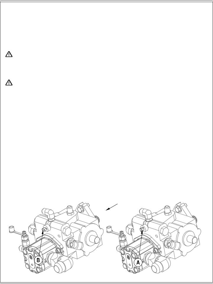
The machine’s drive propelling pump is manufactured with an adjustable tow valve. This valve prevents damage to the hydraulic system when the machine is being towed/pushed short distances without use of the engine.
To access the valve open the Engine Compartment Cover (1) and locate the hydrostatic pump at the rear of the engine. Turn the valve 90 degrees, this disengages the hydrostatic lock between the motor and pump.
CAUTION: The hydraulic propelling pump can be damaged if the machine is towed with the valve in the normal working position (A). Reference the illustration below for the normal working setting (A) (vertical) and the free wheeling towing setting (B) (horizontal). Note: If the tow valve is left in free wheeling (B) (horizontal) position the propelling pump can’t drive the machine FWD or REV. No damage will result, just re-set valve to the normal working setting (A) (vertical). NOTE: Tow or push machine no faster than a normal walking pace (2-3 miles per hour) and for short distances only. If the machine is to be moved long distances the drive wheel needs to be raised off the floor and placed on a suitable transport dolly.
FRONT
FORM NO. 56091065 - SW8000 - A-5
A-6 / ENGLISH
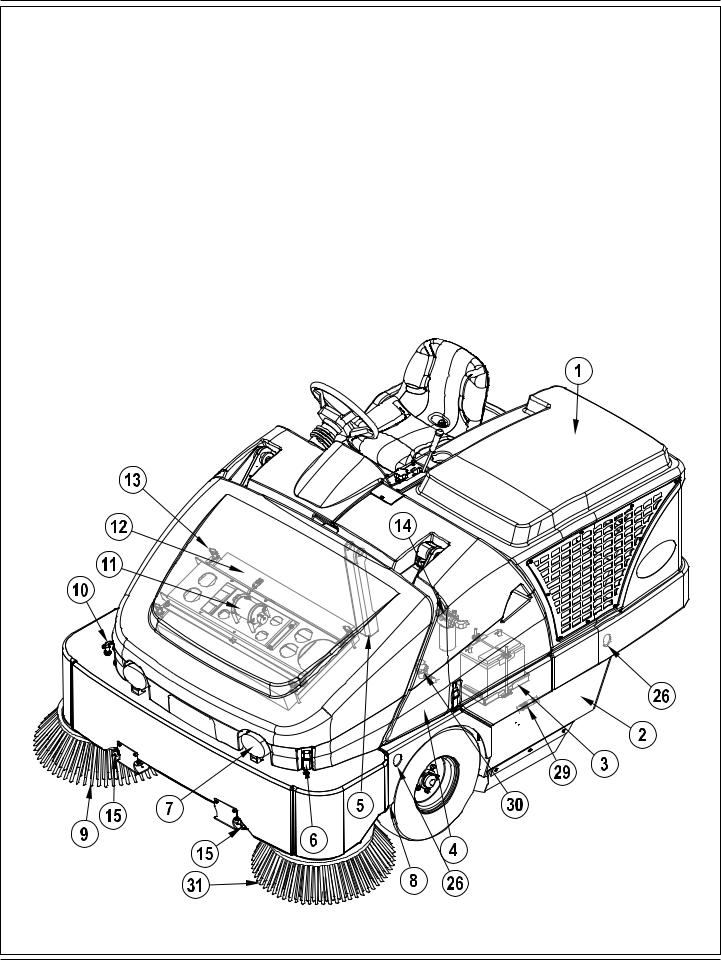
KNOW YOUR MACHINE
As you read this manual, you will occasionally run across a bold number in parentheses - example: (2). These numbers refer to an item on the next four pages. Refer back to these pages whenever necessary to pinpoint the location of an item mentioned in the text.
1Engine Compartment Cover
2Left Side Main Broom Access Panel
3Battery
4Center Cover Assembly
5Hopper Safety Support
6Hopper Cover Latch
7Head Light
8Jacking Locations (rear location is large weight below radiator)
9Right Side Broom
10Side Broom Height Adjustment Knob
11Dust Filter Shaker Assembly
12Hopper Dust Control Filter
13Shaker Assembly Retainer Knobs
14Hydraulic Oil Filter
15Optional DustGuard™ Spray Nozzles
A-6 - FORM NO. 56091065 - SW8000

ENGLISH / A-7
KNOW YOUR MACHINE (CONTINUED)
16Hopper Cover
17Hopper Cover Prop Rod
18Right Side Main Broom Access Panel
19Oil Reservoir
20Oil Reservoir / Fuel Tank Cover
21Fuel Tank (LPG tank shown / Gasoline / Petrol tank is in same location)
22Coolant Recovery Tank
23Radiator Cap
24Engine Air Filter
25Fuel Tank Cover Release Latch
26Tie-Down Locations (5)
27Air Filter Service Indicator
28Optional DustGuard™ Tank Fill
29Optional DustGuard™ Quick Disconnect
30Optional DustGuard™ Solution Strainer
31Optional Left Side Broom
FORM NO. 56091065 - SW8000 - A-7

A-8 / ENGLISH
OPERATOR’S COMPARTMENT
AOperator’s Seat
BMain Broom Lever
CMain Broom Adjust Knob
DControl Panel (See Associated Pages)
ESteering Wheel
FBrake Pedal / Parking Brake
GFWD / REV Drive Pedal
HCircuit Breaker Panel
IHopper Safety Support Handle
JOperator Seat Adjustment Lever
A-8 - FORM NO. 56091065 - SW8000

|
|
|
|
|
|
|
ENGLISH / A-9 |
CONTROL PANEL |
|
|
|
|
|
|
|
AA |
Optional Fuel Gauge (Gasoline / Petrol and Diesel Only) |
|
|
|
|
|
|
BB |
Horn Switch |
|
|
|
|
|
|
CC |
LPG Low Indicator Light |
|
|
|
|
|
|
DD |
Headlight Switch |
|
|
|
|
|
|
EE Engine Service Indicator |
|
|
|
|
|
|
|
FF |
Glow Plug Indicator Light (Diesel Only) |
|
|
|
|
|
|
GG |
Engine Speed Switch |
|
|
|
|
|
|
HH |
Side Broom ON-Down / OFF-Up Switch |
|
|
|
|
|
|
II |
Dust Control Indicator |
|
|
|
|
|
|
JJ |
Dust Control Switch |
|
|
|
|
|
|
KK |
Plugged Filter Indicator |
|
|
|
|
|
|
LL |
Shaker Switch |
|
|
|
|
|
|
MM Hopper UP Indicator |
|
|
|
|
|
|
|
NN |
Open Dump Door Switch |
|
|
XX |
|
|
|
OO |
Hopper Overtemp Indicator |
|
|
|
|
|
|
PP |
Close Dump Door Switch |
|
|
|
|
|
|
Lower Hopper Switch |
|
|
WW |
|
|
|
|
RR |
Raise Hopper Switch |
|
|
|
|
|
|
SS |
Hour Meter |
|
|
|
|
|
|
TT |
Ignition Switch |
|
|
VV |
|
|
|
UU |
Service Indicator Light |
|
|
|
|
|
|
VV |
Optional DustGuard™ Switch |
|
|
|
|
|
|
WW Optional Emergency Flasher Switch |
|
|
|
|
|
|
|
XX |
Optional Turn Signal Switch |
|
|
|
|
|
|
|
AA |
BB |
CC |
DD |
EE |
FF |
|
|
|
|
|
|
GG |
||
|
|
|
|
|
|
|
|
|
|
|
|
|
|
|
HH |
|
|
|
|
|
|
|
II |
|
|
|
|
|
|
|
JJ |
|
|
|
|
|
|
|
KK |
|
|
|
|
|
|
|
LL |
|
|
|
|
|
|
|
MM |
|
|
|
|
|
|
|
NN |
|
TT |
SS |
|
|
|
|
|
|
|
RR |
|
|
|
|
|
|
|
|
|
UU |
PP |
OO |
|
|
|
|
|
|
|
FORM NO. 56091065 - SW8000 - A-9 |
|

A-10 / ENGLISH
PRE-OPERATIONAL CHECKLIST
Before Each Use:
*Inspect the machine for damage, oil or coolant leaks.
*Squeeze the rubber dust cup on the Engine Air Filter (24) to release built-up dust.
*Check the engine coolant level (23).
*Check the engine oil level.
*Check the hydraulic oil level (19).
*Check the Fuel Gauge (AA) on the gasoline / petrol and diesel models.
*Check the Fuel Gauge located on the LPG tank (21) for LPG model.
*Check the tire pressure of all three tires, should be 90-95 psi.
*Check the Air Filter Service Indicator (27).
In the Driver’s Seat:
*Be sure that you understand the operating controls and their functions.
*Adjust the seat to allow easy reach of all controls.
*Insert the Master Key and turn the Ignition Switch (TT) to the ON position. Check for proper operation of the Horn (BB), Hour Meter (SS) and Headlights (DD). Turn the Ignition Key Switch (TT) OFF.
*Check the Parking Brake (F). The brake must hold its (locked parked) setting firmly without easily being released. (Report all defects immediately to service personnel).
Plan Your Cleaning in Advance:
*Arrange long runs with a minimum of stopping or starting.
*Allow 6 inches of broom path overlap to ensure complete coverage.
*Avoid making sharp turns, bumping into posts, or scraping the side of the machine.
MAIN BROOM
Several different main brooms are available for this machine. Contact your Advance dealer if you need help selecting the best broom for the surface and litter that you will be sweeping. Note: Reference broom maintenance for installation steps.
FUEL
WARNING !
•ALWAYS STOP THE ENGINE BEFORE FILLING THE FUEL TANK.
•DO NOT SMOKE WHILE FILLING THE FUEL TANK.
•FILL THE FUEL TANK IN A WELL-VENTILATED AREA.
•DO NOT FILL THE FUEL TANK NEAR SPARKS OR OPEN FLAME.
•USE ONLY THE FUEL SPECIFIED ON THE FUEL TANK DECAL.
DIESEL ENGINE
Fill the tank with Number 2 Diesel Fuel if the machine will be used in an area where the temperature is 32° Fahrenheit (0° Celsius) or higher. Use Number 1 Diesel Fuel if the machine will be used in an area where the temperature is below 32° Fahrenheit (0° Celsius).
NOTE: If the diesel machine runs out of fuel completely, the fuel system must be bled before the engine can be re-started. To avoid this situation, fill the fuel tank when the fuel gauge indicates 1/4 tank. Fuel tank capacity is 12.75 gallons (48.26 liters).
GASOLINE / PETROL ENGINE
FILL THE TANK WITH UNLEADED 87 OCTANE REGULAR GASOLINE / PETROL. FUEL TANK CAPACITY IS 12.75 GALLONS (48.26 LITERS).
Note: Reference the separately supplied engine manufacture’s maintenance and operator manual for more detailed engine specification and service data.
LPG ENGINE
Mount a standard 33 lb. liquid withdrawal LPG tank on the machine, connect the fuel hose and open the shutoff valve on the tank. Wear gloves when connecting or disconnecting the fuel hose. Shut the LPG tank service valve OFF when the machine is not in use.
NOTE: Make sure to properly orient the horizontal LPG tank for liquid withdrawal. After connecting the fuel hose to the tank check for leaks by listening and smelling for gas.
WARNING!
Do not operate the machine if a gas leak is present. Disconnect the fuel hose and replace the LPG tank. If a gas leak is still present disconnect the fuel hose and contact your Advance Service Center.
A-10 - FORM NO. 56091065 - SW8000
ENGLISH / A-11
OPERATING THE MACHINE
The SW8000 is a rider-type automatic floor sweeping machine. The controls were designed with one touch operation in mind. For single pass sweeping the operator can simply lower the main broom and all sweeping functions will be ready to go.
Note: Bold numbers in parentheses indicate an item illustrated on pages 6-9.
BEFORE STARTING THE MACHINE
1Be sure you understand all machine controls and their functions.
2Plan your cleaning route. Arrange long, straight passes with as few turns as possible.
3Check the Brake Pedal (FF). The pedal should be firm.
If the pedal is “spongy” or fades under pressure, DO NOT DRIVE THE MACHINE. Report all defects immediately to service personnel.
STARTING THE DIESEL ENGINE
1Turn the Key Switch (TT) counter-clockwise to the “Pre-Heat” position and hold it there until the Glow Plug Indicator (FF) turns OFF. Once the indicator turns OFF the engine can be started. Skip this step if the engine has been running and is already warm.
2Turn the Key Ignition Switch (TT) clockwise to the START position and release it as soon as the engine starts. If the engine does not start after cranking for 15 seconds, release the key, wait for 1 minute and try steps 1-3 again.
NOTE: The engine starter will not engage if the FWD / REV Drive Pedal (G) is not in the neutral position.
3Let the engine run at “IDLE” speed for 5 minutes before using the machine.
4Push the Engine Speed Switch (GG) to switch to “FULL THROTTLE” and move the machine around for 2 or 3 minutes at a slow speed to warm up the hydraulic system.
STARTING THE LPG & GASOLINE / PETROL ENGINE
1NOTE: LPG models only: Open the service valve on the LP fuel tank (21).
2Turn the Ignition Key Switch (TT) clockwise to the START position and release it as soon as the engine starts. If the engine does not start after cranking for 15 seconds, release the key, wait for 1 minute, then try again.
NOTE: The engine starter will not engage if the FWD / REV Drive Pedal (G) is not in the neutral position.
3Let the engine run at “IDLE” speed for 5 minutes before using the machine.
4Push the Engine Speed Switch (GG) to switch to “FULL THROTTLE” and move the machine around for 2 or 3 minutes at a slow speed to warm up the hydraulic system.
NOTE: ALWAYS operate the machine with the Engine Speed Switch (GG) at full throttle. Use the FWD / REV Drive Pedal (G) - not the Engine Speed Switch (GG) - to control the speed of the machine. The speed of the machine will increase as the pedal is pushed closer to the floor.
FORM NO. 56091065 - SW8000 - A-11

A-12 / ENGLISH
SWEEPING
Follow the instructions in the preparing the machine for use section of the manual.
1While seated on the machine, adjust the seat to a comfortable operating position using the adjustment controls (J).
2Release the Parking Brake (F). To transport the machine to the work area, apply even pressure with your foot on the front of the Drive Pedal
(G) to go forward or the rear of the pedal for reverse. Vary the pressure on the foot pedal to obtain the desired speed.
3Push the Lower Hopper Switch (QQ) to make sure the hopper is seated properly. NOTE: The Hopper UP Indicator (MM) will be illuminated if the hopper is not in the down position.
4Move the Main Broom Lever (B) to the SWEEP (middle notch) position to lower and enable the main broom and dust control systems. NOTE: The dump door opens automatically when the main broom (B) is lowered and closes when the broom is raised.
Use the FULL FLOAT (last notch forward) position only when sweeping extremely rough or uneven floors. Use at other times will only increase broom wear.
5When sweeping floors with puddles, push the Dust Control Switch (JJ) to turn OFF the dust control system before the machine enters a puddle. Turn the dust control system back ON when the machine is back on completely dry floor. NOTE: This is done to prevent the Hopper Dust Control Filter (12) from getting wet.
When sweeping wet floors, keep the Dust Control Switch (JJ) OFF at all times.
6The Side Broom (9) is automatically enabled when the main broom is lowered and starts spinning when the Drive Pedal (G) is activated. The Side Broom (9) can be turned off and back on at any time by pushing the Side Broom Switch (HH).
The side broom sweeping pattern is adjusted by turning the Side Broom Height Adjustment Knob (10).
7Drive the machine straight forward at a quick walking speed. Drive the machine slower when sweeping large amounts of dust or debris or when safe operation dictates slower speeds. Overlap passes 6 inches (15 cm).
8If dust comes out of the broom housing while sweeping, the Dust Control Filter (12) may be clogged. Push the Shaker Switch (LL) to clean the dust control filter. The dust control system (JJ) will automatically turn OFF while the shaker is running and turn ON after the shaker turns OFF (the shaker runs for 15 seconds).
9Check behind the machine occasionally to make sure that the machine is picking up debris. Dirt left behind in the path of the machine usually indicates that the machine is moving too fast, the broom needs to be adjusted, or the hopper is full.
NOTE: If the machine does not move for 40 seconds, the engine will automatically return to idle. The sweep system will only activate with the engine RPM at high. To begin sweeping again press the Engine Speed Switch (GG) to return engine RPM to high.
EMPTYING THE HOPPER
WARNING!
Make sure the Hopper Safety Support (5) is in place whenever attempting to do any maintenance work under or near the raised hopper. The Hopper Safety Support (5) holds the hopper in the raised position to allow work to be performed under the hopper. NEVER rely on the machine’s hydraulic components to safely support the hopper.
NOTE: The MINIMUM ceiling height dumping clearance required for raising the hopper is 102” (259.08 cm)
1Put the Main Broom Lever (B) in the UP / OFF position. NOTE: The Shaker will automatically run for about 15 seconds after the main broom is raised. If you do not raise the main broom, push the Shaker Switch (LL) to remove excess dirt from the dust control filter.
2Drive the machine close to a large trash receptacle and hold the Raise Hopper Switch (RR) until the hopper is all the way up. NOTE: The dump door automatically closes when switch (RR) is pushed. You regain control of the dump door as soon as the hopper begins to raise so you can dump at any height if necessary.
3Move the machine forward until the hopper is over the receptacle and set the Parking Brake (F). Press the Open Dump Door Switch (NN) to open the dump door and empty the hopper. NOTE: If not dumping into a trash receptacle, low dumping is recommended to help eliminate airborne dust.
4Put the Hopper Safety Support (5) in place by pulling back on the Hopper Safety Support Pull Rod (I), then lower the hopper slightly to secure.
5Check the hopper door and the front edge seal. Use a broom, if necessary, to remove litter from these areas. The hopper door must seal tightly against the broom housing bulb gasket for proper operation.
6Return to the operator’s compartment. Release the parking brake. Move the machine back until the hopper will clear the receptacle. Raise the hopper slightly and push forward on the Hopper Safety Support Handle (I) until the Hopper Safety Support (5) disengages, then lower the hopper. NOTE: The brooms will not turn on if the hopper is not completely down. The indicator light (MM) on the control panel should turn OFF indicating that the machine is ready for use.
A-12 - FORM NO. 56091065 - SW8000

ENGLISH / A-13
AFTER USE
1Shake the Hopper Dust Control Filter (LL) and empty the hopper.
2Check the maintenance schedule and perform all required maintenance before storage.
3Move the machine to an indoor storage area.
4Shut down the engine according to the shutdown procedures.
5Make sure the Ignition Switch (TT) is OFF and the Parking Brake (F) is engaged. NOTE: Press Brake Pedal / Parking Brake (F) and rock your foot forward. NOTE: If sweeping organic debris, always empty and clean the hopper before storing to prevent odors.
NOTE: It is safe to clean this machine with a pressure washer as long as you do not spray directly at or into electrical components. The machine should always be allowed to dry completely before each use.
TO SHUT DOWN THE DIESEL & GASOLINE / PETROL ENGINE...
1Raise the brooms.
2Place the Engine Speed Switch (GG) in IDLE and let the engine idle for 25 - 30 seconds.
3Turn the Ignition Key Switch (TT) OFF and remove the key. NOTE: The engine will continue to run for a few seconds after switching the key to off. This is part of the proper operation of the closed loop electronic control system.
4Apply the Parking Brake (F). NOTE: Press Brake Pedal / Parking Brake (F) and rock your foot forward.
TO SHUT DOWN THE LPG ENGINE...
1Raise the brooms.
2Turn the service valve on LPG Tank (21) OFF.
3Run the engine until all the LPG is dispelled from the line (the engine will stall).
4Turn the Ignition Key Switch (TT) OFF and remove the key.
5Apply the Parking Brake (F). NOTE: Press Brake Pedal / Parking Brake (F) and rock your foot forward.
REPORT ANY DEFECT OR MALFUNCTION NOTED DURING OPERATION TO AUTHORIZED SERVICE OR MAINTENANCE PERSONNEL.
MAINTENANCE
Make sure that the machine is kept in top shape by following the maintenance schedule closely. Repairs, when required, should be performed by your Authorized Advance Service Center, who employs factory trained service personnel and maintains an inventory of Advance Original Equipment Replacement Parts and Accessories.
NOTE: Refer to the Service Manual for more detail on maintenance and service repairs.
MAINTENANCE SCHEDULE
Maintenance intervals given are for average operating conditions. Machines used in severe operational environments may require service more often.
MAINTENANCE ITEM |
PERFORM DAILY |
Perform the “After Use” maintenance steps |
X |
Check parking brake |
X |
Check engine oil |
X |
*Clean main and side broom(s) |
X |
Check filter indicator and lights (hyd & air) |
X |
Check engine coolant level |
X |
Check hydraulic oil level |
X |
MAINTENANCE ITEM |
15 hrs. 30 hrs. 150 hrs. 300 hrs. 1000 hrs. |
*Rotate main broom |
X |
Clean the DustGuard™ Spray Nozzles (15) and Strainer (30) |
X |
*Inspect/adjust brooms |
X |
* Check / Clean Hopper Dust Control Filter Using Method “A” |
X |
*Inspect broom housing skirts |
X |
*Inspect hopper seals |
X |
Clean radiator and oil cooler |
X |
Perform engine maintenance |
X |
*Inspect and grease steering spindle |
X |
* Check / Clean Hopper Dust Control Filter Using Method “B” |
X |
* Check / Clean Hopper Dust Control Filter Using Method “C” |
X |
Change the hydraulic oil filter |
X |
Change reservoir hydraulic oil |
X |
Flush the radiator |
X |
Engine fuel filter(s) |
X |
*See the Mechanical Repair Service Manual for detailed maintenance information of systems listed. (Sweeping, Hopper, Steering, Dust Control). NOTE: Cleaning the hopper dust control filter is not required on models using the maintenance free bag filter.
FORM NO. 56091065 - SW8000 - A-13

A-14 / ENGLISH
MAIN BROOM MAINTENANCE
Since the Main Broom Motor always turns in the same direction, the bristles on the broom eventually become curved, reducing sweeping performance. Sweeping performance can be improved by removing the broom and turning it around (end-for-end). This procedure, known as “rotating” the main broom, should be done once every 15 hours of operation. NOTE: This procedure does not apply to the optional chevron broom.
The main broom should be replaced for optimal performance when the bristles are worn to a length of 2 inches (5.08 cm). The Main Broom Adjust Knob (C) must be re-adjusted when the broom is replaced.
NOTE: The machine should be stored with the Main Broom in the raised position.
 WARNING!
The engine must not be running when performing this procedure.
 CAUTION!
Brooms can be sharp. Wear gloves to protect your hands.
To Rotate or Replace the Main Broom...
1Turn the Ignition Switch (TT) OFF.
2Put the Main Broom Lever (B) in the UP position.
3Open the Right Side Main Broom Access Panel (18).
4See Figure 1. Pivot the Idler Arm Assembly (A1) out of the main broom core. NOTE: The Idler Arm is held in place by the Right Side Main Broom Access Panel (18).
5Pull the Main Broom (A2) out of the broom housing and remove any string or wire wrapped around it. Also inspect the skirts at the front, back and sides of the broom housing. The skirts should be replaced or adjusted if they are torn or worn to a height of more than 1/4 inch (6.35
mm)off the ground.
6Turn the broom around (end-for-end) and slide it back into the broom housing. Make sure that the lugs on the broom core (left side) engage the slots in the broom drive hub and that the broom is fully seated.
7Swing the idler arm assembly back into the broom core. NOTE: Make sure the lugs on the idler arm engage the slots in the broom core
8Close and latch the Right Side Main Broom Access Panel (18).
To Adjust the Main Broom Height...
1Drive the machine to an area with a level floor and set the parking brake.
2Move the Main Broom Lever (B) to the SWEEP (middle notch) position to lower the main broom. DO NOT move the machine.
3Lightly press the FWD / REV Drive Pedal (G) to start the main broom and repeat three times. This allows the broom to polish a “strip” on the floor. Raise the broom, release the parking brake and move the machine so that the polished strip is visible.
4Inspect the polished strip on the floor. If the strip is less than 2 inches (5.08 cm) or more than 3 inches (7.62cm) wide, the broom needs to be adjusted.
5To adjust, loosen the Knob (C) and slide forward or backward to lower or raise the Main Broom. The farther the Lever (B) travels forward in the slot, the lower the Main Broom will be. Tighten Knob (C) after adjusting the position of the stop bracket.
6Repeat steps 1-5 until the polished strip is 2-3 inches (5.08-7.62cm) wide.
The width of the polished strip should be the same at both ends of the broom. If the strip is tapered, move the machine to a different area and repeat steps 1-5. If the polished strip is still tapered, contact your Advance Dealer for service.
A-14 - FORM NO. 56091065 - SW8000

ENGLISH / A-15 |
FIGURE 1 |
FORM NO. 56091065 - SW8000 - A-15 |
A-16 / ENGLISH
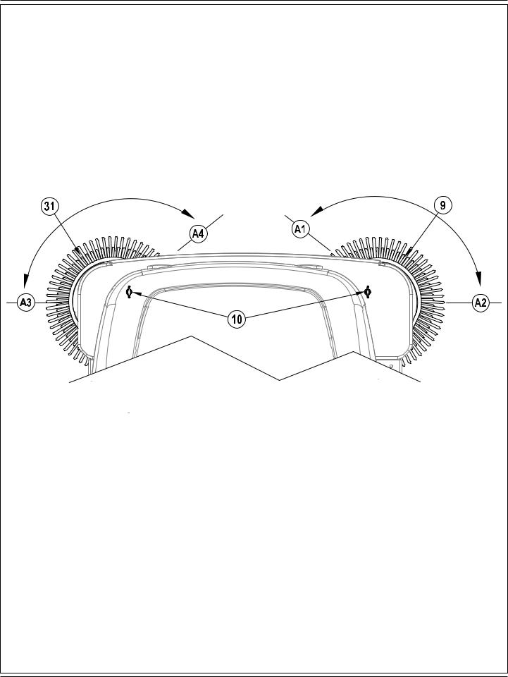
SIDE BROOM MAINTENANCE
To adjust the Side Broom...
1Drive the machine to an area with a level floor and set the parking brake.
2Pull the Main Broom Lever (B) back and slide to the right and up to lower the main and side brooms.
3See Figure 2. When in the Down position, the Right Side Broom (9) should be contacting the floor from the 10 O’Clock (A1) to the 3 O’Clock (A2) area shown. NOTE: Optional Left Side Broom (31) should be contacting the floor from the 9 O’Clock (A3) to the 2 O’Clock (A4) area.
4If either broom requires adjustment, turn the Side Broom Height Adjustment Knob (10) either clockwise to raise or counter-clockwise to lower the side broom.
NOTE: The machine should be stored with the Side Brooms (9 & 31) in the raised position. The Side Brooms (9 & 31) should be replaced when the bristles are worn to a length of 3 inches (7.62 cm) or it becomes ineffective. The Side Broom height must be re-adjusted whenever a broom has been replaced.
FIGURE 2
A-16 - FORM NO. 56091065 - SW8000
ENGLISH / A-17
SIDE BROOM MAINTENANCE
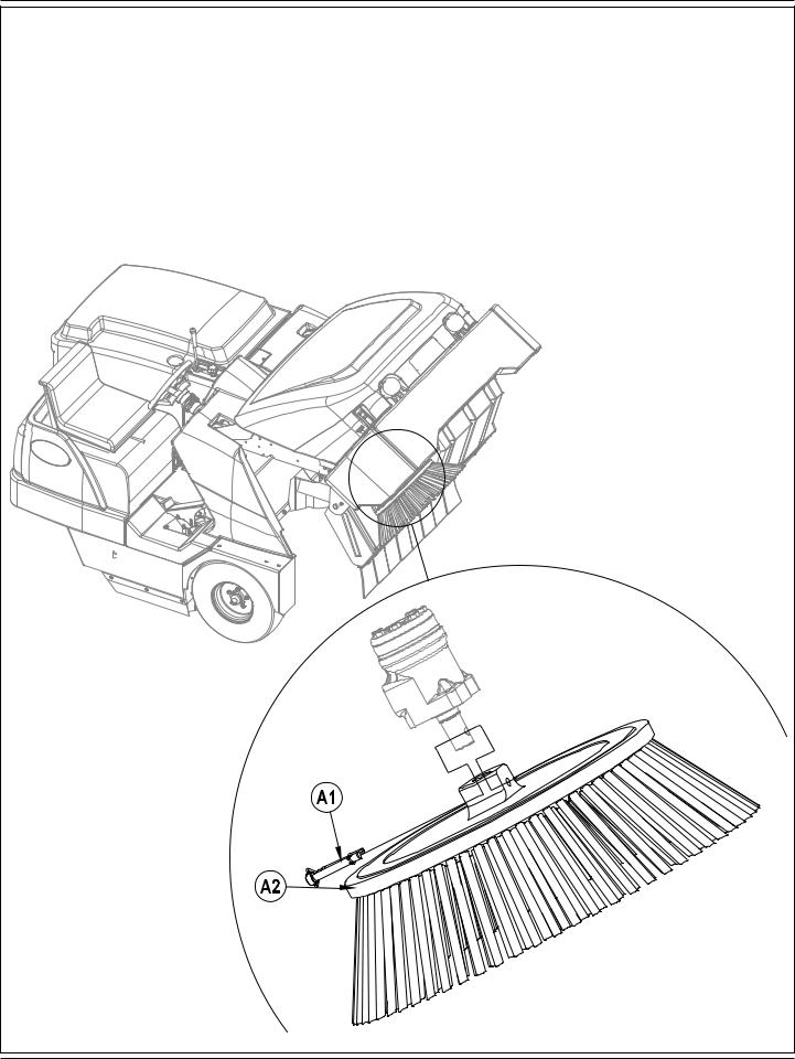
To replace the Side Broom...
1See Figure 3. Raise the hopper until the side broom is approximately at chest height.
2Grab hold of the side broom with both hands and rotate until the ring end of the Hitch Pin (A1) is facing toward the rear of the hopper. NOTE: The side broom(s) will only rotate freely in one direction.
3Remove the Hitch Pin (A1) and pull the Side Broom (A2) off of the motor shaft.
4Slide the new broom onto the motor shaft, line up the pin hole and reinstall the Hitch Pin (A1).
FIGURE 3
FORM NO. 56091065 - SW8000 - A-17

A-18 / ENGLISH
HOPPER DUST CONTROL FILTER (PANEL FILTER)
The hopper dust control filter must be cleaned regularly to maintain the efficiency of the vacuum system. Follow the recommended filter service intervals for the longest filter life.
 CAUTION!
Wear safety glasses when cleaning the filter. Do not puncture the paper filter.
Clean the filter in a well-ventilated area.
Wear appropriate dust mask to avoid breathing in dust.
To remove the hopper dust control filter...
1Unlatch and open the Hopper Cover (16). Make sure that the Hopper Cover Prop Rod (17) is in place.
2Inspect the top of the Hopper Dust Control Filter (12) for damage. A large amount of dust on top of the filter is usually caused by a hole in the filter or a damaged filter gasket.
Inspect the bottom of the Hopper Dust Control Filter (12). If the filter is covered with wet or dry mud, the dust control system will not function properly without replacing or thoroughly cleaning the filter using Method “C”.
3Remove the four Shaker Assembly Retainer Knobs (13). Lift off the Dust Filter Shaker Assembly (11) to access the panel filter.
4Lift the Hopper Dust Control Filter (12) out of the machine.
5Clean the filter using one of the methods below: Method “A”
Vacuum loose dust from the filter. Then gently tap the filter against a flat surface (with the dirty side down) to remove loose dust and dirt. NOTE: Take care not to damage the metal lip which extends past the gasket.
Method “B”
Vacuum loose dust from the filter. Then blow compressed air (maximum pressure 100 psi) into the clean side of the filter (in the opposite direction of the airflow).
Method “C”
Vacuum loose dust from the filter. Then soak the filter in warm water for 15 minutes, then rinse it under a gentle stream of water (maximum pressure 40 psi). Let the filter dry completely before putting it back into the machine.
6Follow the instructions in reverse order to install the filter. If the gasket on the filter is torn or missing, it must be replaced. NOTE: Before replacing filter clear debris from dust plate located under filter. Verify that the debris flap at the rear of the dust plate swings freely
ENGINE RADIATOR AND HYDRAULIC RADIATOR CLEANING
The engine radiator and hydraulic radiator must be occasionally cleaned to prevent overheating and premature wear of engine and hydraulic systems. Follow the recommended service intervals.
CAUTION!
Wear Safety glasses when cleaning the engine radiator and hydraulic heat exchanger.
1Tip back Engine Compartment Cover (1). Disconnect cable latch on the left side of Engine Compartment Cover to allow cover to fully tip back and out of the way.
2Turn the locking mechanism at the top of the hydraulic radiator to allow the hydraulic heat exchanger to fully tip back and away from the radiator for easy cleaning access.
3Blow out engine radiator and hydraulic radiator with air and or use low pressure water to rinse debris from the fins.
NOTE: Do Not use a pressure washer or a mechanical brush to clean fins since this can cause damage to the fins. If fins get bent, carefully straighten them to improve cooling performance.
4Restore hydraulic radiator to raised position and latch into place
5Reconnect Engine Compartment Cover (1) cable and fully return the cover normal operational position
A-18 - FORM NO. 56091065 - SW8000

ENGLISH / A-19
HYDRAULIC OIL
Unlatch and swing open the Oil Reservoir / Fuel tank Cover (20). Remove the reservoir cap to check the oil level. The hydraulic oil level should be half way up the screen filter inside the filler neck of the reservoir. Add SAE 10W30 motor oil if it is below this level. Change the oil if major contamination from a mechanical failure occurs.
ENGINE OIL – GASOLINE / PETROL & LPG
Check the engine oil level when the machine is parked on a level surface and the engine is cool. Change the engine oil after the first 35 hours of operation and every 150 hours after that. Use any SF or SG rated oil meeting API specifications and suited to seasonal temperatures. Refer to the Engine System section for oil capacities and additional engine specifications. Replace the oil filter with every oil change.
TEMPERATURE RANGE |
OIL WEIGHT |
Above 60° F (15° C) |
SAE 10W-30 |
Below 60° F (15° C) |
SAE 5W-30 |
ENGINE OIL - DIESEL
Check the engine oil level when the machine is parked on a level surface and the engine is cool. Change the engine oil after the first 35 hours of operation and every 150 hours after that. Use CF, CF-4 or CG-4 oil meeting API specifications and suited temperatures (*important reference the oil/fuel type note below for further diesel oil recommendations). Refer to the Engine System section for oil capacities and additional engine specifications. Replace the oil filter with every oil change.
TEMPERATURE RANGE |
OIL WEIGHT |
Above 77 °F (25 °C) |
SAE 30 or 10W-30 |
32 °F to 77 °F (0 °C to 25 °C) |
SAE 20 or 10W-30 |
Below 32 °F (0 °C) |
SAE 10W or 10W-30 |
* Diesel Lubricating Oil Note:
With the emission control now in effect, the CF-4 and CG-4 lubricating oils have been developed for use of a low-sulfur fuel on-road vehicle engines. When an off-road vehicle engine runs on a high-sulfur fuel, it is advisable to employ the CF, CD or CE lubricating oil with a high total base number. If the CF-4 or CG-4 lubricating oil is used with a high-sulfur fuel, change the lubricating oil at shorter intervals.
• Lubricating oil recommended when a low-sulfur or high-sulfur fuel is employed.
Lubricating |
Fuel |
Low sulfur |
|
|
|
High sulfur |
Remarks |
||
|
(0.5 % ≥) |
|||
Oil class |
|
|
|
|
|
|
|
|
|
|
|
|
|
|
CF |
|
O |
O |
TBN ≥ 10 |
CF-4 |
|
O |
X |
|
CG-4 |
|
O |
X |
|
O : Recommendable |
X : Not recommendable |
|
|
|
ENGINE COOLANT
Open the Engine Compartment Cover (1) and observe the coolant level in the Coolant Recovery Tank (22). If the level is low, add a mixture of half water and half automotive type anti-freeze.
CAUTION!
Do not remove the Radiator Cap (23) when the engine is hot.
ENGINE AIR FILTER
Check the Engine Air Filter Service Indicator (24) before each use of the machine. Do not service the air filter unless the red flag is visible in the service indicator. NOTE: After cleaning or replacing the engine air filter, the service indicator can be reset by pressing the end of the indicator.
CAUTION!
When servicing the engine air filter elements, use extreme care to prevent loose dust from entering the engine. Dust can severely damage the engine.
The engine air filter contains a Primary (outer) and a Safety (inner) filter element. The Primary Element may be cleaned twice before being replaced. The Safety Element should be replaced every third time that the Primary Filter Element is replaced. Never attempt to clean the Inner Safety Element.
To clean the Primary Filter Element, unsnap the 2 clips at the end of the air filter and remove the end housing. Pull the primary element out. Clean the element with compressed air (maximum pressure 100 psi) or wash it with water (maximum pressure 40 psi). DO NOT put the element back into the canister until it is completely dry.
Empty dust from the outer plastic housing by squeezing the rubber flap. Orientate flap down when reinstalling.
FORM NO. 56091065 - SW8000 - A-19
A-20 / ENGLISH |
|
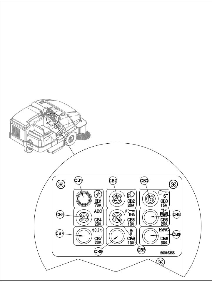
CIRCUIT BREAKER LOCATION |
|
CB1 |
Main (70A) |
CB2 |
Headlights (20A) |
CB3 |
Starter (15A) |
CB4 |
Accessory (20A) |
CB5 |
Ignition (10A) |
CB6 |
Shaker (20A) |
CB7 |
Turn Signals (20A) |
CB8 |
Mister (10A) |
CB9 |
HVAC (30A) |
A-20 - FORM NO. 56091065 - SW8000 |
|
ENGLISH / A-21
TROUBLESHOOTING
If the possible causes listed below are not the source of trouble, it is a symptom of something more serious. Contact your Advance Service Center immediately for service.
TRIPPING THE CIRCUIT BREAKERS
The circuit breakers are located on the Circuit Breaker Panel (H), they protect electrical circuits and motors from damage due to overload conditions. If a circuit breaker trips, try to determine the cause.
Main Circuit Breaker (CB1 / 70 Amp) Possible cause may be:
1 Electrical short circuit or overload (have your Advance Service Center or qualified electrician check the machine)
Headlight Circuit Breaker (CB2 / 20 Amp) Possible cause may be:
1 Electrical short circuit or overload (have your Advance Service Center or qualified electrician check the machine)
Starter Motor Circuit Breaker (CB3 / 15 Amp) Possible causes may be:
1 Electrical short circuit or overload (have your Advance Service Center or qualified electrician check the machine)
Accessory Circuit Circuit Breaker (CB4 / 20 Amp) Possible cause may be:
1 Electrical short circuit or overload (have your Advance Service Center or qualified electrician check the machine)
Ignition Circuit Circuit Breaker (CB5 / 10 Amp) Possible cause may be:
1 Electrical short circuit or overload (have your Advance Service Center or qualified electrician check the machine)
Shaker Circuit Breaker (CB6 / 20 Amp) Possible cause may be:
1 Electrical short circuit or overload (have your Advance Service Center or qualified electrician check the machine)
Turn Signal Circuit Breaker (CB7 / 20 Amp) Possible cause may be:
1 Electrical short circuit or overload (have your Advance Service Center or qualified electrician check the machine)
Mister Circuit Breaker (CB8 / 10 Amp) Possible cause may be:
1 Electrical short circuit or overload (have your Advance Service Center or qualified electrician check the machine)
HVAC Circuit Breaker (CB9 / 30 Amp) Possible cause may be:
1 Electrical short circuit or overload (have your Advance Service Center or qualified electrician check the machine)
Once the problem has been corrected, push the button in to reset the circuit breaker. If the button does not stay in, wait 5 minutes and try again. If the circuit breaker trips repeatedly, call your Advance Service Center for service.
FORM NO. 56091065 - SW8000 - A-21

A-22 / ENGLISH
TROUBLESHOOTING
If the possible causes listed below are not the source of trouble, it is a symptom of something more serious. Contact your Advance Service Center immediately for service.
MACHINE WILL NOT START
Possible causes may be:
1FWD / REV Drive Pedal not in neutral position (ensure pedal is in neutral position)
2FWD / REV Drive Pedal neutral position is not correctly set (contact your Advance service center)
3Battery is not connected or dead (connect or charge battery)
4Machine is out of fuel or LPG tank valve is not open (refuel or open LPG tank valve)
5Tripped circuit breaker(s) (reset any tripped circuit breakers)
MACHINE WILL NOT MOVE
Possible causes may be:
1Parking Brake (F) set (release parking brake)
2Towing Valve in wrong position (set correctly)
3Tripped circuit breaker(s) (reset any tripped circuit breakers)
MAIN BROOM WILL NOT RUN
Possible causes may be:
1Engine not set to high RPM (push Engine Speed Switch (GG))
2Debris wrapped around the broom drive (remove debris)
3Hopper is not completely down (lower hopper completely)
4Tripped circuit breaker(s) (reset any tripped circuit breakers)
SIDE BROOM WILL NOT RUN
Possible causes may be:
1Engine not set to high RPM (push Engine Speed Switch (GG))
2Ensure Side Broom OFF switch isn’t selected (push switch to turn ON)
3Debris wrapped around the broom drive (remove debris)
4Hopper is not completely down (lower hopper completely)
5Tripped circuit breaker(s) (reset any tripped circuit breakers)
HOPPER WILL NOT RAISE
Possible causes may be:
1Engine not set to high RPM (push Engine Speed Switch (GG))
2Tripped circuit breaker(s) (reset any tripped circuit breakers)
HOPPER DUMP DOOR WILL NOT OPEN
Possible causes may be:
1Dump door jammed by debris (remove debris and clean edges of dirt chamber)
2Tripped circuit breaker(s) (reset any tripped circuit breakers)
SHAKER MOTOR WILL NOT RUN
Possible causes may be:
1Tripped circuit breaker(s) (reset any tripped circuit breakers)
2Electrical connection to shaker motor disconnected (connect shaker motor)
DUST CONTROL SYSTEM (IMPELLER) WILL NOT RUN
Possible causes may be:
1Tripped circuit breaker(s) (reset any tripped circuit breakers)
2Ensure Dust Control OFF switch isn’t selected (push switch to turn ON)
DUSTGUARD™ SIDE BROOM MIST SYSTEM WILL NOT FUNCTION
Possible causes may be:
1DustGuard™ Switch (VV) not turned ON (turn ON DustGuard Switch)
2Main Broom Lever (B) not actuated (lower main broom)
3Water tank is empty (fill water tank (28))
4Mist Nozzles (15) are clogged (clean Mist Nozzles (15))
A-22 - FORM NO. 56091065 - SW8000

ENGLISH / A-23
ACCESSORIES / OPTIONS
In addition to the standard components, the machine can be equipped with the following accessories/options, according to the machine specific use:
Main and side brooms with harder or softer bristlesPolyester Water Resistant dust filter
Clogged filter sensorDustGuard™ systemFire extinguisher
Working light
Amber Strobe lightNon-marking wheelsTilt steering wheel
Driver’s seat with suspensionsSafety belts
Side broom guard
Spark Arrestor Exhaust
Metal Hopper Bottom Plate
Raised Engine Air Intake with Pre-FilterOverhead Guard
Overhead guard canopyRearview mirrors
Rear Metal bumperLeft Hand Side BroomEnclosed Cabin
Floor Mat
Engine Gauges
Hopper Fire High Temp SensorBack Up Audio Alarm
Tail, Brake and Turn SignalsFoam Filled Tires
Solid Tires
For further information about the above-mentioned accessories, contact an authorized Retailer.
TECHNICAL SPECIFICATIONS (as installed and tested on the unit)
Model |
|
SW8000 |
SW8000 |
SW8000 |
|
|
4 cyl. LPG |
4 cyl. Gasoline / Petrol |
4 cyl. Diesel |
Model No. |
|
56107503 |
56107501 |
56107505 |
Protection Grade |
|
IPX3 |
IPX3 |
IPX3 |
Sound Pressure Level |
|
|
|
|
(IEC 60335-2-72: Ed 3 2012, ISO 11201) |
dB(A) |
80.6dB LpA, 3dB KpA |
80.6dB LpA, 3dB KpA |
82.78dB LpA, 3dB KpA |
Sound Power Level |
|
|
|
|
(IEC 60335-2-72: Ed 3 2012, ISO 3744) |
dB(A) |
102.3 dB LWA |
102.3 dB LWA |
106.3 dB LWA |
Gross Weight |
lbs/kg |
4426 / 2007 |
4426 / 2007 |
4426 / 2007 |
Empty Weight |
lbs/kg |
3075 / 1395 |
3075 / 1395 |
3075 / 1395 |
Maximum Wheel Floor Loading (right front) |
psi/ N/mm2 |
72 / 0.496 |
72 / 0.496 |
65 / 0.448 |
Maximum Wheel Floor Loading (left front) |
psi/ N/mm2 |
63 / 0.434 |
63 / 0.434 |
65 / 0.448 |
Maximum Wheel Floor Loading (rear center) |
psi/ N/mm2 |
71 / .489 |
71 / .489 |
76 / 0.524 |
Vibrations at the Hand Controls (ISO 5349-1) |
m/s2 |
1.08 m/s2 |
1.08 m/s2 |
1.5 m/s2 |
Vibrations at the Seat (ISO 2631-1) |
m/s2 |
0.15 m/s2 |
0.15 m/s2 |
0.16 m/s2 |
Gradeability |
|
20%(11.3º) |
20%(11.3º) |
20%(11.3º) |
Model |
|
SW8000 (cab) |
SW8000 (cab) |
SW8000 (cab) |
|
|
4 cyl. LPG |
4 cyl. Gasoline / Petrol |
4 cyl. Diesel |
Model No. |
|
56107509 |
56107507 |
56107511 |
Protection Grade |
|
IPX3 |
IPX3 |
IPX3 |
Sound Pressure Level |
|
|
|
|
(IEC 60335-2-72: Ed 3 2012, ISO 11201) |
dB(A) |
80.6dB LpA, 3dB KpA |
80.6dB LpA, 3dB KpA |
82.78dB LpA, 3dB KpA |
Sound Power Level |
|
|
|
|
(IEC 60335-2-72: Ed 3 2012, ISO 3744) |
dB(A) |
102.3 dB LWA |
102.3 dB LWA |
106.3 dB LWA |
Gross Weight |
lbs/kg |
4775 / 2165 |
4775 / 2165 |
4775 / 2165 |
Empty Weight |
lbs/kg |
3424 / 1553 |
3424 / 1553 |
3424 / 1553 |
Maximum Wheel Floor Loading (right front) |
psi/ N/mm2 |
72 / 0.496 |
72 / 0.496 |
65 / 0.448 |
Maximum Wheel Floor Loading (left front) |
psi/ N/mm2 |
63 / 0.434 |
63 / 0.434 |
65 / 0.448 |
Maximum Wheel Floor Loading (rear center) |
psi/ N/mm2 |
71 / .489 |
71 / .489 |
76 / 0.524 |
Vibrations at the Hand Controls (ISO 5349-1) |
m/s2 |
1.08 m/s2 |
1.08 m/s2 |
1.5 m/s2 |
Vibrations at the Seat (ISO 2631-1) |
m/s2 |
0.15 m/s2 |
0.15 m/s2 |
0.16 m/s2 |
Gradeability |
|
20%(11.3º) |
20%(11.3º) |
20%(11.3º) |
FORM NO. 56091065 - SW8000 - A-23

B-2 / ESPAÑOL
ÍNDICE
|
Página |
Introducción............................................................................... |
B-2 |
Componentes y servicio ............................................................ |
B-2 |
Placa de identificación............................................................... |
B-3 |
Desembalaje de la máquina...................................................... |
B-3 |
Precauciones y advertencias..................................................... |
B-4 |
Información general................................................................... |
B-5 |
Conozca su máquina...................................................... |
B-6 - B-9 |
Preparación de la máquina para el uso |
|
Comprobaciones previas a la utilización ................................. |
B-10 |
Cepillo principal ....................................................................... |
B-10 |
Combustible............................................................................. |
B-10 |
Manejo de la máquina |
|
Antes de encender la máquina................................................ |
B-11 |
Encendido del motor diésel ..................................................... |
B-11 |
Encendido del motor de gasolina ............................................ |
B-11 |
Encendido del motor de propano líquido (PL)......................... |
B-11 |
Barrido..................................................................................... |
B-12 |
Vaciado de la tolva .................................................................. |
B-12 |
Después de la utilización de la máquina |
|
Después de la utilización......................................................... |
B-13 |
Para apagar el motor de gasolina/diésel................................. |
B-13 |
Para apagar el motor de propano líquido................................ |
B-13 |
Mantenimiento |
|
Programa de mantenimiento ................................................... |
B-13 |
Mantenimiento del cepillo principal.......................................... |
B-14 |
Mantenimiento del cepillo lateral ............................................. |
B-16 |
Filtro de control de polvo de la tolva........................................ |
B-18 |
Limpieza del radiador del motor y del radiador hidráulico ....... |
B-18 |
Aceite hidráulico ...................................................................... |
B-19 |
Aceite de motor ....................................................................... |
B-19 |
Refrigerante del motor............................................................. |
B-19 |
Filtro de aire del motor............................................................. |
B-19 |
Ubicación de los disyuntores................................................... |
B-20 |
Solución de problemas............................................................ |
B-21 |
Accesorios / Opciones............................................................. |
B-23 |
Especificaciones técnicas........................................................ |
B-23 |
INTRODUCCIÓN
Este manual le ayudará a obtener el máximo rendimiento de su Barredora Advance. Léalo con atención antes de utilizar la máquina.
Nota: Los números que aparecen en negrita entre paréntesis indican elementos ilustrados en las páginas 6-9.
COMPONENTES Y SERVICIO
Las reparaciones, en caso necesario, deben ser realizadas por el personal de servicio de Advance con repuestos y accesorios Advance originales.
Llame a Advance para lo referente a piezas de repuesto y servicio. Por favor, especifique el modelo y el número de serie cuando hable de su máquina.
B-2 - FORM NO. 56091065 - SW8000

ESPAÑOL / B-3
MODIFICACIONES
Las modificaciones y los agregados a la máquina de limpieza que afecten su capacidad y su funcionamiento seguro no serán realizados por el cliente o el usuario sin la autorización previa y por escrito de Nilfisk-Advance Inc. Las modificaciones que no cuenten con la aprobación correspondiente anularán la garantía de la máquina y harán que el cliente sea responsable de cualquier accidente resultante.
PLACA DE IDENTIFICACIÓN
El Modelo y el Número de Serie de la máquina están indicados en la Placa de identificación situada en el lado derecho de la máquina. Esta información es necesaria a la hora de solicitar repuestos para la máquina. Utilice el siguiente espacio para anotar el modelo y el número de serie de su máquina para futuras consultas.
MODELO ______________________________________________
NÚMERO DE SERIE _____________________________________
DESEMBALAJE DE LA MÁQUINA - SI CORRESPONDE
Tras la entrega, inspeccione con atención la caja de transporte y la máquina para ver si se han producido daños. Si los daños son evidentes, guarde todas las partes de la caja de transporte, de manera que la compañía de transporte que entregó la máquina pueda inspeccionarla. Póngase en contacto con la compañía de transporte inmediatamente para presentar una reclamación por daños durante el transporte.
1Después de retirar la caja, retire los bloques de madera situados junto a las ruedas.
2Compruebe el nivel de aceite y refrigerante del motor.
3Compruebe el nivel del aceite hidráulico.
4Lea las instrucciones de la sección “Preparación de la máquina para su utilización” de este manual y llene el depósito de combustible.
5Coloque una rampa junto al extremo frontal del palé.
6Lea las instrucciones de las secciones “Funcionamiento de los controles” y “Funcionamiento de la máquina” de este manual y encienda el motor. Desplace despacio la máquina para bajarla por la rampa hasta el suelo. Mantenga el pie pisando ligeramente el pedal del freno hasta que la máquina haya bajado del palé.
¡PRECAUCIÓN!
Extreme las PRECAUCIONES al utilizar esta barredora. Antes de utilizarla, debe conocer bien todas sus instrucciones de funcionamiento. Si tiene alguna duda, consulte con su supervisor o con el distribuidor industrial de Advance de su zona.
En caso de funcionamiento incorrecto de su barredora, no intente solucionar el problema a menos que se lo ordene su supervisor. Solicite la ayuda de un mecánico cualificado de su empresa o de una persona autorizada por el Servicio del Proveedor Advance para que efectúen las correcciones necesarias en el equipo.
Extreme las precauciones al trabajar en esta máquina. Existe el peligro de que las corbatas, prendas sueltas, pelo largo, anillos y pulseras queden atrapados entre los componentes móviles. Apague el interruptor de llave (TT), retire la llave, eche el freno de estacionamiento (F) y desconecte la batería antes de utilizar la máquina. Utilice el sentido común, respete las normas de seguridad y preste atención a las pegatinas amarillas colocadas en la máquina.
Conduzca la máquina lentamente en pendientes. Use el pedal de freno (F) para controlar la velocidad de la máquina al descender las pendientes. NO gire la máquina en una pendiente; conduzca en línea recta hacia arriba o hacia abajo.
 La pendiente nominal máxima durante el transporte es del 20%.
* Nota: Si desea datos más detallados sobre especificaciones y servicio del motor, consulte el manual de utilización y mantenimiento del motor elaborado por el fabricante y entregado por separado.
 ¡ADVERTENCIA!
Los Productos a la venta con este Manual contienen, o pueden contener, productos químicos reconocidos por algunos gobiernos (como el Estado de California, según lo indica en su Proposición 65, Ley de Advertencia Regulatoria) como causantes de cáncer, defectos de nacimiento u otros daños reproductivos. En algunas jurisdicciones (incluido el Estado de California), los compradores de estos Productos que los coloquen en servicio en un emplazamiento laboral o en un espacio de acceso público tienen la obligación regulatoria de realizar determinados avisos, advertencias o divulgaciones respecto de los productos químicos contenidos o posiblemente contenidos en los Productos utilizados en tal lugar. Es la responsabilidad del comprador conocer y cumplir con todas las leyes y reglamentaciones relacionadas con el uso de estos Productos en tales entornos. El Fabricante niega toda responsabilidad de informar a los compradores sobre requisitos específicos que pueden regir el uso de los Productos en tales entornos.
FORM NO. 56091065 - SW8000 - B-3

B-4 / ESPAÑOL
PRECAUCIONES Y ADVERTENCIAS SÍMBOLOS
Advance utiliza los símbolos que se indican más abajo para señalar situaciones potencialmente peligrosas. Lea siempre con atención esta información y tome las medidas necesarias para la protección de las personas y la propiedad.
¡PELIGRO!
Se utiliza para advertir de riesgos inmediatos que producirán lesiones personales graves o incluso fatales.
¡ADVERTENCIA!
Se utiliza para llamar la atención sobre una situación que podría producir lesiones personales graves.
¡PRECAUCIÓN!
Se utiliza para llamar la atención sobre una situación que podría provocar lesiones personales leves o daños en la máquina u otros objetos.
Lea todas las instrucciones antes de utilizar la máquina.
INSTRUCCIONES GENERALES DE SEGURIDAD
Se incluyen precauciones y advertencias específicas que advierten de los peligros potenciales de daños a la máquina o lesiones personales. Esta máquina sólo es apropiada para uso comercial, por ejemplo en plantas de fabricación, depósitos, instalaciones de bloques de cemento y ladrillos, estacionamientos, parques municipales, instalaciones de entretenimiento e instalaciones de transporte.
¡PELIGRO!
*Esta máquina emite gases de escape (monóxido de carbono) que pueden producir lesiones graves e incluso fatales; facilite siempre la ventilación adecuada cuando utilice la máquina.
¡ADVERTENCIA!
*Esta máquina únicamente deben utilizarla personas autorizadas y con la debida formación.
*Esta máquina no debe ser utilizada por personas (incluidos niños) con capacidades físicas, sensoriales o mentales reducidas, o con falta de experiencia y conocimientos.
*Al circular sobre rampas o pendientes, evite las paradas bruscas. Evite las curvas muy cerradas. Circule lentamente al bajar rampas.
*Para evitar la introducción de aceite hidráulico bajo la piel u otras lesiones provocadas por aceite hidráulico, utilice siempre las ropas y la protección ocular apropiados cuando trabaje con el sistema hidráulico o cerca de él.
*Apague el interruptor de contacto (O) y desconecte las baterías antes de realizar mantenimiento o reparaciones en los componentes eléctricos.
*Nunca trabaje debajo de una máquina sin colocar antes bloques o soportes de seguridad que sostengan la máquina.
*No aplique sustancias limpiadoras inflamables ni utilice la máquina sobre estas sustancias o cerca de ellas, ni tampoco en zonas en las que haya líquidos inflamables.
*Use solamente los cepillos suministrados junto con el aparato o aquellos especificados en el manual de instrucciones. El uso de otros cepillos puede afectar negativamente a la seguridad.
*No utilice la máquina sin una estructura protectora para objetos que caen en las áreas en las que el operador tiene probabilidades de ser golpeado por objetos en caída.
*Las máquinas deberán estacionarse de forma segura.
*La máquina deberá ser inspeccionada con frecuencia por una persona cualificada, particularmente el recipiente de propano líquido y sus conectores, según lo requiera la operación segura indicada por las normas regionales o nacionales.
*Observe el peso bruto del vehículo (GVW) de la máquina cuando cargue, maneje, eleve o sostenga la máquina.
¡PRECAUCIÓN!
*Esta máquina no ha sido aprobada para su uso en vías públicas.
*Esta máquina está aprobada sólo para uso sobre superficie dura.
*Esta máquina no es apta para recoger polvos peligrosos.
*Cuando utilice la máquina, asegúrese de que no existe peligro para terceras personas, especialmente niños.
*Antes de realizar cualquier función de mantenimiento o reparación, lea con atención todas las instrucciones relativas a la misma.
*No abandone la máquina sin antes apagar el interruptor de contacto (O), retirar la llave y aplicar el freno de estacionamiento.
*Apague el interruptor de contacto (O) y quite la llave antes de cambiar los cepillos y antes de abrir cualquiera de los paneles de acceso.
*Tome las debidas precauciones para evitar que el cabello, las joyas o las prendas sueltas queden atrapados entre elementos en movimiento.
*Antes de utilizar la máquina, todas las puertas y cubiertas deberían asegurarse adecuadamente.
*Retire la batería de la máquina antes de su desmantelamiento. La batería debe desecharse de forma segura, de acuerdo con la reglamentación medioambiental vigente en su zona.
*No utilice la máquina en superficies con pendientes superiores a las indicadas en la máquina.
*Antes de utilizar la máquina, todas las puertas y cubiertas deberían estar colocadas como se indica en el manual de instrucciones.
GUARDE ESTAS INSTRUCCIONES
B-4 - FORM NO. 56091065 - SW8000
ESPAÑOL / B-5
SOPORTE DE SEGURIDAD DE LA TOLVA
 ¡ADVERTENCIA!
Compruebe que el Soporte de Seguridad de la Tolva (5) se encuentra colocado cuando vaya a realizar alguna operación de mantenimiento debajo de la tolva levantada o cerca de ella. El Soporte de Seguridad de la Tolva (5) mantiene la tolva en posición elevada para permitir la realización de operaciones debajo de la tolva. No se limite NUNCA a los componentes hidráulicos de la máquina solamente para soportar la tolva de manera segura.
ELEVACIÓN DE LA MÁQUINA
¡PRECAUCIÓN!
No trabaje nunca debajo de la máquina sin colocar antes los soportes o bloques de seguridad para apoyar la máquina.
•Cuando eleve la máquina, aplique los gatos en los lugares indicados (No en la tolva) – véase puntos de elevación (8).
TRANSPORTE DE LA MÁQUINA
¡PRECAUCIÓN!
Antes de transportar la máquina sobre un camión o remolque abierto, asegúrese de...
•cerrar bien todas las puertas de acceso
•sujetar bien la máquina, de forma que quede segura
•echar el freno de estacionamiento de la máquina.
REMOLQUE O EMPUJE DE LA MÁQUINA EN CASO DE AVERÍA
La bomba de propulsión de transmisión de la máquina lleva una válvula de remolque ajustable que impide que se produzcan daños en el sistema hidráulico en caso de que deba remolcarse/empujarse la máquina a una distancia corta sin el uso del motor.
Para acceder a la válvula, abra la cubierta del compartimiento del motor (1) y localice la bomba hidrostática en la parte trasera del motor. Gire la válvula 90 grados. De esta forma desacoplará el bloqueo entre el motor y la bomba.
PRECAUCIÓN: La bomba de propulsión hidráulica puede sufrir daños si se remolca la máquina con la válvula en posición normal de funcionamiento (A). Consulte en la ilustración que aparece más adelante el ajuste normal de funcionamiento (A) (vertical) y el ajuste de giro libre para remolque (B) (horizontal). Nota: si la válvula de remolque se deja en posición de giro libre (B) (horizontal), la bomba de propulsión no podrá desplazar la máquina hacia delante ni hacia atrás. No se producirá ningún daño; sólo tiene que volver a situar la válvula en el ajuste normal de funcionamiento (A) (vertical). NOTA: No remolque ni empuje la máquina a una velocidad superior a la del paso normal de una persona (3-5 km/h) y hágalo solamente en distancias cortas. Si necesita desplazar la máquina una larga distancia, la rueda motriz debe elevarse del suelo y colocarse sobre un gato rodante.
FRONT
FORM NO. 56091065 - SW8000 - B-5

B-6 / ESPAÑOL
CONOZCA SU MÁQUINA
A lo largo de este manual encontrará números en negrita entre paréntesis – por ejemplo: (2). Estos números se refieren a uno de los elementos que aparecen en las siguientes cuatro páginas. Consulte estas páginas siempre que lo necesite para localizar alguna pieza o componente citado en el texto.
1Cubierta del compartimento del motor
2Panel de acceso del cepillo principal izquierdo
3Batería
4Conjunto de cubierta central
5Soporte de seguridad de la tolva
6Pestillo de la cubierta de la tolva
7Faro delantero
8Puntos de elevación (la ubicación trasera tiene el mayor peso debajo del radiador)
9Cepillo lateral derecho
10Mando de ajuste de altura del cepillo lateral
11Agitador del filtro de polvo
12Filtro de control de polvo de la tolva
13Botones de retén del conjunto del vibrador
14Sustituir el filtro y el aceite hidráulico
15Boquillas de rociado DustGuard™ opcionales
B-6 - FORM NO. 56091065 - SW8000
 Loading...