


BSM-2300
Table of contents
 Loading...
BEDSIDE MONITOR
BSM-2300A/K
0634-001878B
SERVICE MANUAL
BSM- 2301A
BSM- 2301K
BSM- 2303K
BSM- 2304A
WS- 231P
QI- 231P
QI- 236P

BEDSIDE MONITOR
BSM-2300A/K
0634-001878B
BSM- 2301A
BSM- 2301K
BSM- 2303K
BSM- 2304A
WS- 231P
QI- 231P
QI- 236P

Model: BSM-2300A/K
Manual code no.: 0634-001878B
Reader Comment Card
We welcome your comments about this manual. Your comments and suggestions help us improve our
manuals. Please circle the number for each of the following statements corresponding to your evaluation
and add comments in the space provided.
Fax or send your completed comment card to:
Fax: +81 (3) 5996-8100
International Div., Sales Promotion Section, Nihon Kohden Corp., 1-31-4, Nishiochiai Shinjuku-ku, Tokyo
161-8560, Japan
Strongly Agree Neutral Disagree Strongly
Agree Disagree
This manual is organized. 1 2 3 4 5
I can find the information I want. 1 2 3 4 5
The information is accurate. 1 2 3 4 5
I can understand the instructions. 1 2 3 4 5
The illustrations are appropriate and helpful. 1 2 3 4 5
The manual length is appropriate. 1 2 3 4 5
Comments:
Thank you for your cooperation. We appreciate it very much.
Name:
Occupation/Position:
Hospital/Company:
Address:
Phone:
cutting line

CONTENTS
Service Manual BSM-2300 C.1
Contents
EMC Related Caution ....................................................................................................i
Conventions Used in this Manual and Instrument ...................................................... iii
Warnings, Cautions and Notes ......................................................................... iii
Explanations of the Symbols in this Manual and Instrument ........................... i v
On panels ..........................................................................................................i v
On screen.......................................................................................................... v
Others................................................................................................................ v
Section 1 General....................................................................................1C.1
Introduction ......................................................................................................................... 1.1
General Information on Servicing ...................................................................................... 1.2
Service Policy, Service Parts and Patient Safety Checks ................................................ 1.4
Service Policy .......................................................................................................... 1.4
Service Parts ........................................................................................................... 1.4
Patient Safety Checks .............................................................................................. 1.5
Specifications ..................................................................................................................... 1.6
Display ........................................................................................................... 1.6
Sound ............................................................................................................. 1.6
Alarm .............................................................................................................. 1.6
ECG ................................................................................................................ 1.6
Respiration (Transthoracic impedance pneumography) ................................ 1.7
SpO2 on BSM-2301A/K and BSM-2303K ...................................................... 1.8
SpO2 on BSM-2304A ..................................................................................... 1.8
Non Invasive Blood pressure, NIBP .............................................................. 1.8
Temperature ................................................................................................... 1.9
Multi-parameter Amplifier............................................................................... 1.9
Invasive Blood Pressure, IBP ........................................................................ 1.9
Respiration (Thermistor method) ................................................................... 1.9
Expired Carbon Dioxide Tension, CO2.......................................................... 1.10
Trendgraph .................................................................................................... 1.10
Vital Signs List ..............................................................................................1.10
Recorder Module (optional, WS-231P) .........................................................1.10
Interface (optional, QI-231P)......................................................................... 1.11
Interface (optional, QI-236P)......................................................................... 1.11
External Output .............................................................................................1.11
Power Requirement .......................................................................................1.11
Clock Accuracy .............................................................................................1.12
Environment ..................................................................................................1.12
Dimensions and Weight (approximate) .........................................................1.12
Electromagnetic Compatibility ......................................................................1.12
Safety Standard .............................................................................................1.12
Composition....................................................................................................................... 1.13
Panel Descriptions ............................................................................................................1.14

CONTENTS
C.2 Service Manual BSM-2300
Front Panel ..............................................................................................................1.14
Left Side Panel ........................................................................................................1.16
BSM-2301A/K and BSM-2303K..................................................................... 1.16
BSM-2304A ...................................................................................................1.17
Right Side Panel ......................................................................................................1.18
Storage and Transport ....................................................................................................... 1.19
Storage ....................................................................................................................1.19
Transport .................................................................................................................1.19
Hard Keys and Soft Keys ..................................................................................................1.20
Hard Keys ................................................................................................................1.20
Soft Keys .................................................................................................................1.20
Upgrading the System Software and Changing Language on the Screen ........................1.21
Procedure ...................................................................................................... 1.21
Block Diagram ................................................................................................................... 1.22
BSM-2300 ................................................................................................................ 1.22
WS-231P Recorder Module ....................................................................................1.23
QI-231P Interface ....................................................................................................1.24
QI-236P Interface ....................................................................................................1.25
Section 2 Troubleshooting ..................................................................... 2C.1
General ............................................................................................................................... 2.1
Power-Related Problems .................................................................................................... 2.2
Display Problems ............................................................................................................... 2.3
Sound Problems ................................................................................................................. 2.4
Key Operation Problems .................................................................................................... 2.4
ECG and Respiration by Impedance Method Problems .................................................... 2.5
SpO2 Problems .................................................................................................................. 2.6
Non-invasive Blood Pressure Problems ............................................................................ 2.7
Temperature Problems ....................................................................................................... 2.8
Other Vital Sign Input Problems ......................................................................................... 2.9
Option Problems ................................................................................................................ 2.10
Recording Problems ..........................................................................................................2.11
QI-231P Interface Problems .............................................................................................. 2.13
QI-236P Interface Problems .............................................................................................. 2.13
Section 3 Diagnostic Check ...................................................................3C.1
Introduction ......................................................................................................................... 3.1
Power On Self Check ......................................................................................................... 3.2
Calling Up the DIAGNOSTIC CHECK Screen ................................................................... 3.4
Calling Up the Error History ............................................................................................... 3.5
Error Codes .............................................................................................................. 3.5
System Errors .......................................................................................................... 3.6
Initializing the System ........................................................................................................ 3.7
Performing Manual Check and Other Checks .................................................................... 3.8
Calling Up the MANUAL CHECK MENU Screen ..................................................... 3.9
CPU Check Menu Items ......................................................................................... 3.10
ROM Check................................................................................................... 3.10

CONTENTS
Service Manual BSM-2300 C.3
RAM Check ...................................................................................................3.11
Hard Key Check ............................................................................................3.12
Touch Key Check ..........................................................................................3.13
Sound Check ................................................................................................. 3.14
ALARM INDICATOR Check .......................................................................... 3.15
OTHER Check ...............................................................................................3.16
MEMORY CARD Check ................................................................................3.17
Backlight Check ............................................................................................3.18
CRTC Check Menu Items .......................................................................................3.19
GRAPHIC MEMORY Check and CHARACTER MEMORY Check ...............3.19
GRAPHIC DRAW Check ...............................................................................3.20
CHARACTER DRAW Check ......................................................................... 3.22
IMAGE DRAW Check ....................................................................................3.24
DPU Check Menu Items ......................................................................................... 3.25
D/A ADJUST .................................................................................................3.25
AD TEST .......................................................................................................3.26
ZB I/F Check .................................................................................................3.27
NIBP Check................................................................................................... 3.28
DPU ROM Check ..........................................................................................3.38
DPU RAM Check .......................................................................................... 3.39
Power FREQ .................................................................................................3.40
APU Check Menu Items .......................................................................................... 3.41
APU ROM Check ..........................................................................................3.41
APU RAM Check........................................................................................... 3.42
COM Check Menu Items.........................................................................................3.43
WS RECORDER Check ................................................................................3.43
SERIAL I/F Check ......................................................................................... 3.44
NETWORK CARD Check.............................................................................. 3.45
BATTERY Check ........................................................................................... 3.47
MULTI PARAMETER UNIT Check ................................................................3.48
ECG Check ...................................................................................................3.49
OUTPUT Check ............................................................................................3.49
Recorder and Control Block Checks ...................................................................... 3.50
SELF-TEST-PRO No.1 ..................................................................................3.50
SELF-TEST-PRO No.2 ..................................................................................3.51
SELF-TEST-PRO No.3 ..................................................................................3.52
Calibration of Touch Screen .................................................................................... 3.53
Section 4 Board/Unit Description .......................................................... 4C.1
MAIN Board ........................................................................................................................ 4.1
Analog Board ...................................................................................................................... 4.5
ECG/RESP Block ..................................................................................................... 4.5
SpO2 and MP Blocks ............................................................................................... 4.6
SpO2 Block .................................................................................................... 4.6
MP Block ........................................................................................................ 4.7
IBP Board ........................................................................................................................... 4.8
NIBP Board ......................................................................................................................... 4.9
Power Supply Block........................................................................................................... 4.10

CONTENTS
C.4 Service Manual BSM-2300
LCD Unit ............................................................................................................................4.11
Recorder Module (Option) ................................................................................................. 4.12
REC MAIN Board .................................................................................................... 4.12
Recorder Unit ..........................................................................................................4.13
Interface (Option, QI-231P) ............................................................................................... 4.14
ECG, QRS Synch or Alarm Trigger Signal Output Block .......................................4.15
Serial Data Communication Relay Block ................................................................4.15
RGB Relay Block..................................................................................................... 4.15
Interface (Option, QI-236P) ............................................................................................... 4.16
ECG and QRS Synch Trigger Signal Output Block................................................. 4.17
RGB Relay Block..................................................................................................... 4.17
Section 5 Disassembly and Assembly ..................................................5C.1
Removing the Chassis Block ............................................................................................. 5.1
Replacing the MAIN Board ................................................................................................. 5.6
Replacing the Analog Board ..............................................................................................5.10
Replacing the NIBP Board ................................................................................................5.12
Replacing the IBP Board ...................................................................................................5.13
Replacing the Inverter Board ............................................................................................5.14
Replacing the LCD Unit ..................................................................................................... 5.16
Replacing the Lithium Battery ...........................................................................................5.18
Replacing the Backlight Lamp Unit ...................................................................................5.19
Replacing the Battery Pack............................................................................................... 5.22
When the Recorder Module is Not Attached to the Instrument .............................. 5.22
When the Recorder Module is Attached to the Instrument ....................................5.24
Replacing the IO ANALOG OUT or IO CT OUT Board of the Optional Interface ............. 5.26
Section 6 Maintenance ...........................................................................6C.1
To Be Replaced Periodically ............................................................................................... 6.1
Required Tools .................................................................................................................... 6.1
Measuring and Test Equipment .......................................................................................... 6.2
Maintenance Check Items and Schedule........................................................................... 6.3
External .................................................................................................................... 6.3
Input Conditions ....................................................................................................... 6.3
Operation .................................................................................................................. 6.4
Display...................................................................................................................... 6.4
Recorder................................................................................................................... 6.4
Interface ................................................................................................................... 6.5
Vital Sign Parameters .............................................................................................. 6.5
Power ........................................................................................................................ 6.6
Data Backup ............................................................................................................. 6.6
Safety........................................................................................................................ 6.7
Others ....................................................................................................................... 6.7

CONTENTS
Service Manual BSM-2300 C.5
Section 7 Adjustment .............................................................................7C.1
Sensors in the Recorder Unit ............................................................................................. 7.1
Adjusting the Output Voltages with Digital or Analog Multimeter ............................ 7.1
Section 8 Replaceable Parts List ...........................................................8C.1
Bedside Monitor BSM-2300................................................................................................ 8.2
Optional Recorder Module WS-231P ................................................................................. 8.8
RG-922P Recorder Unit ....................................................................................................8.10
QI-231P Interface ..............................................................................................................8.12
QI-236P Interface ..............................................................................................................8.13
Section 9 Connector Pin Assignment ....................................................9C.1
MAIN Board ........................................................................................................................ 9.1
CN0201 (for Alarm Indicator board)............................................................... 9.1
CN0202 (for CN101 on Operation board)....................................................... 9.1
CN0204 (for CN001 on REC MAIN board of optional recorder module) ....... 9.2
CN0205 (for CN002 on REC MAIN board of optional recorder module) ....... 9.3
CN401 (for power supply unit) ....................................................................... 9.3
CN0601 (for program card or network card).................................................. 9.4
CN0701 (for touch screen)............................................................................. 9.5
CN0801 (AUX socket) .................................................................................... 9.5
CN0802 (for Inverter board) ........................................................................... 9.6
CN1001 (for LCD unit) ................................................................................... 9.7
CN1401 (for rechargeable battery pack) ....................................................... 9.8
CN1501 (for CN901 on Analog board) ........................................................... 9.8
CN1502 (for CN0101 on NIBP board) ............................................................ 9.9
Alarm Indicator Board ....................................................................................................... 9.10
CN0101 (for CN0201 on MAIN board) ..........................................................9.10
Analog Board .....................................................................................................................9.11
CN502 ............................................................................................................ 9.11
CN601 (for CN001 on IBP board)..................................................................9.11
CN602 ............................................................................................................ 9.12
CN901 (for CN1501 on MAIN board) ............................................................9.12
CN902 (for ZB-900P transmitter) .................................................................. 9.12
NIBP Board ........................................................................................................................ 9.13
CN0101 (for CN1502 on MAIN board) ..........................................................9.13
CN0102 (for Hall Sensor board) ....................................................................9.13
CN0103 (for line frequency detection coil wire) ........................................... 9.13
CN0104 (for pediatric valve) .........................................................................9.13
CN0105 (for safety circiut valve) ..................................................................9.13
CN0106 (for pump) ........................................................................................ 9.14
CN0107 (for speaker).................................................................................... 9.14
CN0108 (for adult valve) ...............................................................................9.14
IBP Board ..........................................................................................................................9.14
CN001 (for CN601 on Analog board) ............................................................9.14
Operation Board ................................................................................................................ 9.15
CN101 (for CN0202 on MAIN board) ............................................................9.15
CN102 (for CN103 on Power SW board) ...................................................... 9.15

CONTENTS
C.6 Service Manual BSM-2300
Power SW Board ............................................................................................................... 9.16
CN0103 (for CN102 on Operation board)...................................................... 9.16
Inverter Board ................................................................................................................... 9.16
CN1 (for CN0802 on MAIN board) ................................................................ 9.16
CN2 (for backlight) ........................................................................................ 9.16
Hall Sensor Board ............................................................................................................. 9.17
CN101 (for CN102 on NIBP board) ...............................................................9.17
REC MAIN Board ..............................................................................................................9.17
CN001 (for CN0204 on MAIN board) ............................................................9.17
CN002 (for CN0205 on MAIN board) ............................................................9.17
CN003 (for CN103 on REC Power board) .....................................................9.17
REC Key Board .................................................................................................................9.18
CN201 (for CN104 on REC Power board) .....................................................9.18
REC Power Board.............................................................................................................. 9.18
CN101 (for recorder unit) .............................................................................. 9.18
CN102 (for recorder unit) .............................................................................. 9.19
CN103 (for CN003 on REC MAIN board)...................................................... 9.19
CN104 (for CN201 on REC Key board)......................................................... 9.19
IO ANALOG OUT Board ...................................................................................................9.20
CN001 ............................................................................................................ 9.20
CN002 ............................................................................................................ 9.20
CN005 ............................................................................................................ 9.20
CN003 ............................................................................................................ 9.21
CN004 ............................................................................................................ 9.21
IO CT OUT Board .............................................................................................................. 9.22
CN002 ............................................................................................................ 9.22
CN003 ............................................................................................................ 9.22

Service Manual BSM-2300 i
EMC RELATED CAUTION
This equipment and/or system complies with the International Standard IEC60601-1-2 for electromagnetic
compatibility for medical electrical equipment and/or system. However, an electromagnetic environment that
exceeds the limits or levels stipulated in the IEC60601-1-2, can cause harmful interference to the equipment
and/or system or cause the equipment and/or system to fail to perform its intended function or degrade its
intended performance. Therefore, during the operation of the equipment and/or system, if there is any
undesired deviation from its intended operational performance, you must avoid, identify and resolve the
adverse electromagnetic effect before continuing to use the equipment and/or system.
The following describes some common interference sources and remedial actions:
1. Strong electromagnetic interference from a nearby emitter source such as an authorized radio station or
cellular phone:
Install the equipment and/or system at another location if it is interfered with by an emitter source such
as an authorized radio station. Keep the emitter source such as cellular phone away from the equipment
and/or system.
2. Radio-frequency interference from other equipment through the AC power supply of the equipment and/
or system:
Identify the cause of this interference and if possible remove this interference source. If this is not
possible, use a different power supply.
3. Effect of direct or indirect electrostatic discharge:
Make sure all users and patients in contact with the equipment and/or system are free from direct or
indirect electrostatic energy before using it. A humid room can help lessen this problem.
4. Electromagnetic interference with any radio wave receiver such as radio or television:
If the equipment and/or system interferes with any radio wave receiver, locate the equipment and/or
system as far as possible from the radio wave receiver.
If the above suggested remedial actions do not solve the problem, consult your Nihon Kohden Corporation
subsidiary or distributor for additional suggestions.
The CE mark is a protected conformity mark of the European Community. The products herewith comply
with the requirements of the Medical Device Directive 93/42/EEC.
The CE mark only applies to the BSM-2300K bedside monitor.
This equipment complies with International Standard IEC60601-1-2 (1993) which requires CISPR11, Group 1,
Class B. Class B EQUIPMENT is equipment suitable for use in domestic establishments and in
establishments directly connected to a low voltage power supply network which supplies buildings used for
domestic purposes.

ii Service Manual BSM-2300
This page is intentionally left blank.

Service Manual BSM-2300 iii
Conventions Used in this Manual and Instrument
Warnings, Cautions and Notes
Warnings, cautions and notes are used in this manual to alert or signal the reader to specific information.
WARNING
A warning alerts the user to the possible injury or death associated with the use or misuse of the
instrument.
CAUTION
A caution alerts the user to possible injury or problems with the instrument associated with its use or
misuse such as instrument malfunction, instrument failure, damage to the instrument, or damage to other
property.
NOTE
A note provides specific information, in the form of recommendations, prerequirements, alternative methods
or supplemental information.
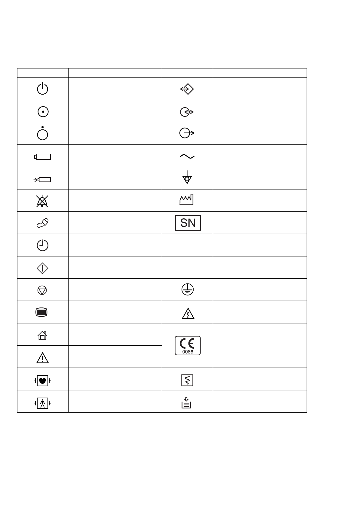
iv Service Manual BSM-2300
Symbol Description Symbol Description
AC operation Data input/output
“On” only for a part of instrument Input/output terminal
“Off” only for a part of instrument Output terminal
Battery operation Alternating current
Battery charging Equipotential terminal
Alarm suspend Year of manufacture
NIBP Serial number
NIBP interval Splash-proof equipment
NIBP start Watertight equipment
NIBP stop Protective earth
Menu High voltage
Home (monitoring screen)
Attention, consult operator’s
manual
The CE mark is a protected
conformity mark of the European
Community. The products herewith
comply with the requirements of the
Medical Device Directive
93/42/EEC.
Defibrillation-proof type CF applied
part
Record start/stop (on the WS-231P
recorder module)
Defibrillation-proof type BF applied
part
Out of paper (on the WS-231P
recorder module)
Explanations of the Symbols in this Manual and Instrument
The following symbols found in this manual/instrument bear the respective descriptions as given.
On panel
IPX4
IPX7
The CE mark only applies to BSM-2301K/2303K monitors.
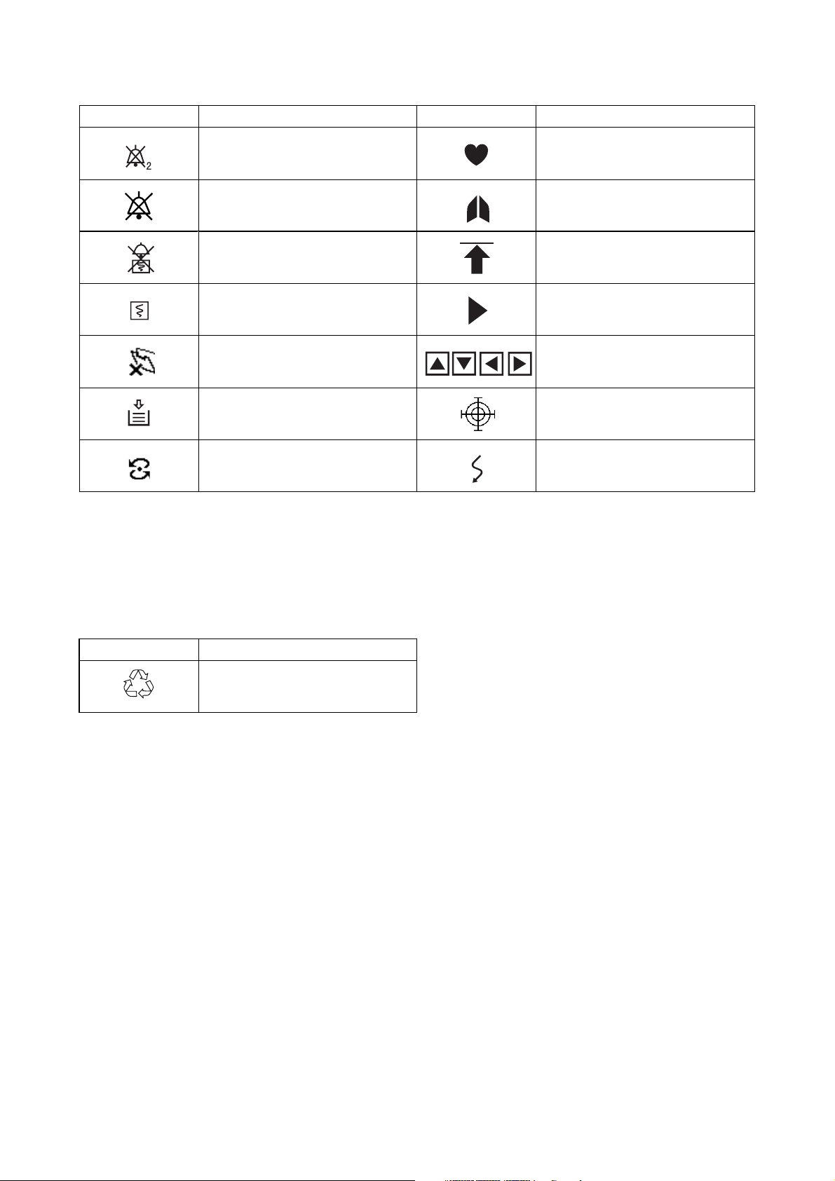
Service Manual BSM-2300 v
Symbol Description Symbol Description
Alarm silence with remaining
minutes
QRS/pulse sync mark
Alarm off Respiration sync mark
Alarm recording off Value out of range
Recording Current measuring value
Paper magazine open Adjust setting/Scroll data
Out of paper Touch screen calibration mark
Network communicating Waveform cascaded
On screen
Others
Symbol Description
Recycle (On battery pack)
Ni-MH

Service Manual BSM-2300 1C.1
Section 1 General
Introduction ........................................................................................................................ 1.1
General Information on Servicing ..................................................................................... 1.2
Service Policy, Service Parts and Patient Safety Checks ............................................... 1.4
Service Policy ......................................................................................................... 1.4
Service Parts .......................................................................................................... 1.4
Patient Safety Checks ............................................................................................. 1.5
Specifications .................................................................................................................... 1.6
Display .......................................................................................................... 1.6
Sound ............................................................................................................ 1.6
Alarm ............................................................................................................. 1.6
ECG ............................................................................................................... 1.6
Respiration (Transthoracic impedance pneumography) ............................... 1.7
SpO2 on BSM-2301A/K and BSM-2303K ..................................................... 1.8
SpO2 on BSM-2304A .................................................................................... 1.8
Non Invasive Blood pressure, NIBP ............................................................. 1.8
Temperature .................................................................................................. 1.9
Multi-parameter Amplifier.............................................................................. 1.9
Invasive Blood Pressure, IBP ....................................................................... 1.9
Respiration (Thermistor method) .................................................................. 1.9
Expired Carbon Dioxide Tension, CO2......................................................... 1.10
Trendgraph ................................................................................................... 1.10
Vital Signs List .............................................................................................1.10
Recorder Module (optional, WS-231P) ........................................................1.10
Interface (optional, QI-231P)........................................................................ 1.11
Interface (optional, QI-236P)........................................................................ 1.11
External Output ............................................................................................1.11
Power Requirement ......................................................................................1.11
Clock Accuracy ............................................................................................1.12
Environment .................................................................................................1.12
Dimensions and Weight (approximate) ........................................................1.12
Electromagnetic Compatibility .....................................................................1.12
Safety Standard ............................................................................................ 1.12
Composition...................................................................................................................... 1.13
Panel Descriptions ...........................................................................................................1.14

1C.2 Service Manual BSM-2300
Front Panel .............................................................................................................1.14
Left Side Panel .......................................................................................................1.16
BSM-2301A/K and BSM-2303K.................................................................... 1.16
BSM-2304A ..................................................................................................1.17
Right Side Panel .....................................................................................................1.18
Storage and Transport ...................................................................................................... 1.19
Storage ...................................................................................................................1.19
Transport ................................................................................................................1.19
Hard Keys and Soft Keys ................................................................................................. 1.20
Hard Keys ...............................................................................................................1.20
Soft Keys ................................................................................................................1.20
Upgrading the System Software and Changing Language on the Screen .......................1.21
Procedure .....................................................................................................1.21
Block Diagram .................................................................................................................. 1.22
BSM-2300 ...............................................................................................................1.22
WS-231P Recorder Module ...................................................................................1.23
QI-231P Interface ...................................................................................................1.24
QI-236P Interface ...................................................................................................1.25

1. GENERAL
Service Manual BSM-2300 1.1
Introduction
This service manual provides useful information to qualified personnel to
understand, troubleshoot, service, maintain and repair the BSM-2300 bedside
monitor (referred to as “the instrument” in this service manual).
All replaceable parts or units of this instrument are clearly listed with exploded
illustration to help you locate the parts quickly.
The “Maintenance” section in this service manual describes the maintenance that
should be performed by qualified service personnel. The “Maintenance” section in
the operator’s manual describes the maintenance that can be performed by the user.
The information in the operator’s manual is primarily for the user. However, it is
important for service personnel to thoroughly read the operator’s manual and
service manual before starting to troubleshoot, service, maintain or repair this
instrument. This is because service personnel need to understand the operation of
the instrument in order to effectively use the information in the service manual.

1. GENERAL
1.2 Service Manual BSM-2300
General Information on Servicing
Note the following information when servicing the instrument.
CAUTION
Safety
••
••
• There is the possibility that the outside surface of the instrument,
such as the operation keys, could be contaminated by contagious
germs, so disinfect and clean the instrument before servicing it.
When servicing the instrument, wear rubber gloves to protect
yourself from infection.
••
••
• There is the possibility that when the lithium battery is broken, a
solvent inside the lithium battery could flow out or a toxic substance
inside it could come out. If the solvent or toxic substance touches
your skin or gets into your eye or mouth, immediately wash it with a
lot of water and see a physician.
Liquid Ingress
The instrument is not drip-proof, so do not install the instrument where
water or liquid can get into or fall on the instrument. If liquid
accidentally gets into the instrument or the instrument accidentally
drops into liquid, disassemble the instrument, clean it with clean water
and dry it completely. After reassembling, verify that there is nothing
wrong with the patient safety checks and function/performance checks.
If there is something wrong with the instrument, contact your Nihon
Kohden representative to repair.
Environmental Safeguards
Depending on the local laws in your community, it may be illegal to
dispose of the lithium battery and CRT unit in the regular waste
collection. Check with your local officials for proper disposal
procedures.
Disinfection and Cleaning
To disinfect the outside surface of the instrument, wipe it with a non-
abrasive cloth moistened with any of the disinfectants listed below. Do
not use any other disinfectants or ultraviolet rays to disinfect the
instrument.
- Chlorohexidine gluconate solution: 0.5%
- Benzethonium chloride solution: 0.2%
- Glutaraldehyde solution: 2.0%
- Benzalkonium chloride: 0.2%
- Hydrochloric alkyldiaminoethylglycine: 0.5%

1. GENERAL
Service Manual BSM-2300 1.3
Transport
••
••
• Use the specified shipment container and packing material to
transport the instrument. If necessary, double pack the instrument.
Also, put the instrument into the shipment container after packing so
that the buffer material does not get into the inside of the instrument.
••
••
• When transporting the board or unit of the instrument, be sure to use
a conductive bag. Never use an aluminum bag when transporting the
power board, power unit or board on which a lithium battery is
mounted. Also, never use a styrene foam or plastic bag which
generates static electricity to wrap the board or unit of the
instrument.
Handling the Instrument
••
••
• Because the outside surface of the instrument is made of resin, the
outside surface of the instrument is easily damaged. So when
handling the instrument, remove clutter from around the instrument
and be careful to not damage the instrument or get it dirty.
••
••
• Because most of the boards in the instrument are multilayer boards
with surface mounted electrical devices (SMD), when removing and
soldering the electrical devices, a special tool is required. To avoid
damaging other electrical components, do not remove and solder
SMD components yourself.
Measuring and Test Equipment
Maintain the accuracy of the measuring and test equipment by
checking and calibrating it according to the check and calibration
procedures.

1. GENERAL
1.4 Service Manual BSM-2300
Service Policy, Service Parts and Patient Safety Checks
Service Policy
Service Parts
Our technical service policy for this instrument is to replace the faulty unit, board
or part or damaged mechanical part with a new one. Do not perform electrical
device or component level repair of the multilayer board or unit. We do not support
component level repair outside the factory for the following reasons:
• Most of the boards are multilayer boards with surface mounted electrical
devices, so the mounting density of the board is too high.
• A special tool or high degree of repair skill is required to repair the multilayer
boards with surface mounted electrical devices.
Disassemble the instrument or replace a board or unit in an environment where the
instrument is protected against static electricity.
As background knowledge for repair, pay special attention to the following:
• You can reduce the repair time by considering the problem before starting repair.
• You can clarify the source of most of the troubles using the information from the
diagnostic check function of the instrument. Refer to “Diagnostic Check “ of this
manual.
Refer to “Replaceable Parts List” of this manual for the service parts for technical
service that we provide.
NOTE
When ordering parts or accessories from your Nihon Kohden
representative, please quote the NK code number and part name which
is listed in this service manual, and the name or model of the unit in
which the required part is located. This will help us to promptly attend
to your needs. Always use parts and accessories recommended or
supplied by Nihon Kohden Corporation to assure maximum
performance from your instrument.

1. GENERAL
Service Manual BSM-2300 1.5
Patient Safety Checks Periodic maintenance procedures and diagnostic check procedures are provided in
this manual to ensure that the instrument is operating in accordance with its design
and production specifications. To verify that the instrument is working in a safe
manner with regard to patient safety, patient safety checks should be performed on
the instrument before it is first installed, periodically after installation, and after any
repair is made on the instrument.
For patient safety checks, perform the following checks as described in the
International Electrotechnical Commission’s standard, IEC60601-1 (1988):
• Protective earth resistance check
• Earth leakage current check
• Enclosure leakage current check
• Patient leakage current check
• Withstanding voltage check

1. GENERAL
1.6 Service Manual BSM-2300
Specifications
Display
Display size: 8.4 inch, TFT type color LCD
Waveform display mode: Non-fade moving or non-fade fixed
Viewing area: 170.4 mm × 127.8 mm
Resolution: 800 × 600 dots
Maximum number of waveform trace: BSM-2301A/K: 5 traces
BSM-2303K/2304A: 6 traces
Sweep speed: 25 mm/s, 50 mm/s (Respiration and CO
2
low speed: 1.56 mm/s)
Sweep time: about 124 mm (5 s, at 25 mm/s sweep speed)
Waveform display color: 12
Numeric display color: 12
Waveform freeze: Provided
Display waveforms: ECG, respiration, IBP, SpO
2
pulse wave and CO
2
Numerical data display: Heart rate, VPC rate, ST level, respiration rate, IBP (systolic, diastolic, mean), NIBP
(systolic, diastolic, mean), SpO
2
, pulse rate, temperature and ETCO
2
Synchronization mark: Heart rate sync mark, pulse rate sync mark, respiratory sync mark
Sound
Sound type: Alarm, synchronization, click
Alarm sound: 3 types
Synchronization sound: Pitch variable for IBP and SpO
2
Alarm
Alarm items: Upper/lower limits alarm, apnea alarm, arrhythmia alarm, connector disconnection
alarm, noise alarm, electrode off alarm, pulse waveform detecting alarm, probe off
alarm, cuff/hose check alarm, sensor check alarm, battery weak alarm, operating
environment alarm
Alarm levels: Crisis (red blinking), Warning (yellow blinking), Advisory (yellow lighting)
Alarm indication: Alarm indicator, highlighted message, alarm sound
Alarm suspend: Provided (for 1 or 2 min)
ECG
Electrode offset potential tolerance: ±500 mV
Input dynamic range: ± 5 mV
Internal noise: ≤30 µVp-p (Refer to input)
Common mode rejection ratio: ≥95 dB
Input impedance ≥5 MΩ (at 10 Hz)
Input bias current: ≤100 nA
Heart rate count
Calculation method: Moving average/Instantaneous beat to beat (selectable)
Counting range: 0, 12 to 300 beats/min (±2 beats/min)
Arrhythmia analysis
Analysis method: Template matching method
Number of channels: 1 channel
VPC counting rate: 0 to 99 VPCs/min

1. GENERAL
Service Manual BSM-2300 1.7
Arrhythmia message: ASYSTOLE, VT, VF, VPC RUN, COUPLET, EARLY VPC, BIGEMINY, FREQ VPC,
TACHYCARDIA, BRADYCARDIA
Arrhythmia recall:
Number of recall files: 16
Storage time per file: 8 s
ST level measurement:
Number of measurement channels:1 ch
Measuring range: ±2.5 mV
Alarm limits: ±2.0 mV in 0.01 mV steps, OFF
Pacemaker pulse rejection capability: 0.1 to 2 ms, ±2 to 700 mV
ANSI/AAMI EC 13-1992 compatible
Pacing pulse detection ON/OFF
Defibrillation-proof: ECG input protected against 400 J
IEC 60601-2-27 17.101 compatible
ESU interference filter: Provided
Filters ON: Time constant 0.5 s, AC hum filter 0.3 to 23 Hz (> −3 dB), ≤ −16 dB (50 Hz or
60 Hz)
OFF: Time constant 3.2 s, 0.05 to 150 Hz (> −3 dB)
Lead:
3-electrode cable: I, II, III
6-electrode cable: I, II, III, aVR, aVL, aVF, V4, V5
Waveform display:
Display sensitivity: 10 mm/mV ±5% (at ×1 sensitivity)
Sensitivity control: ×1/4, ×1/2, ×1, ×2, ×4, or AUTO
Pacing spike display: Available
Heart rate display update cycle: Every 3 s or when alarm is generated
Alarm items:
Upper limit range: 20 to 300 beats/min in 5 beats/min steps, OFF
Lower limit range: OFF, 15 to 295 beats/min in 5 beats/min steps
Alarm items: TACHYCARDIA, BRADYCARDIA, ASYSTOLE
Respiration (Transthoracic impedance pneumography)
Measuring lead: R-F or R-L
Measuring impedance available range: 0 to 2 kΩ
Internal noise: ≤0.2 Ω (Refer to input)
Excitor current: 30 ±10 µArms at 40 kHz
Frequency response: 3.0 Hz ±1 Hz (−3 dB) (Hardware specification)
Time constant: 1.5 s ±0.5 s (Hardware specification)
Respiration counter counting range: 0 to 150 breaths/min
Respiration rate counting accuracy: ±2 breaths/min
Defibrillation proof: Respiration input protected against 400 J discharge
Waveform display:
Display sensitivity: 10 mm/Ω ±20% (at ×1 sensitivity, Zo=480 Ω)
Sensitivity control: ×1/4, ×1/2, ×1, ×2, ×4
Measurement On/Off: Available
Respiration rate display update cycle: Every 3 s or when alarm is generated
Alarm:
Upper limit range: 2 to 150 breaths/min in 2 breaths/min steps, OFF
Lower limit range: OFF, 0 to 148 breaths/min in 2 steps
Apnea time: OFF, 5 to 40 s in 5 s steps

1. GENERAL
1.8 Service Manual BSM-2300
SpO
2
on BSM-2301A/K and BSM-2303K
Measuring range: 50 to 100%
Pulse rate counting range: 0, 30 to 300 beats/min
SpO
2
accuracy: ±2 digits (80% ≤ SpO
2
≤ 100%)
±3 digits (50% ≤ SpO
2
< 80%)
SpO
2
display:
Pulse rate display update cycle: Every 3 s or when alarm is generated
Sync tone modulation: Change in 20 steps at 81 to 100% SpO
2
Waveform sensitivity: ×1/8, ×1/4, ×1/2, ×1, ×2, ×4, ×8
Alarm:
Upper limit range: 51 to 100% SpO
2
in 1% SpO
2
steps, OFF
Lower limit range: OFF, 50 to 99% SpO
2
in 1% SpO
2
steps
SpO
2
on BSM-2304A
Measuring range: 1 to 100%
Pulse rate counting range: 0, 20 to 250 beats/min
SpO
2
accuracy: Adult: ±2 digits (70% ≤ SpO
2
≤ 100%)
Neonate: ±3 digits (70% ≤ SpO
2
< 100%)
SpO
2
display:
Pulse rate display update cycle: Every 3 s or when alarm is generated
Sync tone modulation: Change in 20 steps at 81 to 100% SpO
2
Waveform sensitivity: ×1/8, ×1/4, ×1/2, ×1, ×2, ×4, ×8
Alarm:
Upper limit range: 51 to 100% SpO
2
in 1% SpO
2
steps, OFF
Lower limit range: OFF, 50 to 99% SpO
2
in 1% SpO
2
steps
Non Invasive Blood pressure, NIBP
Measuring method: Oscillometric
Measuring range: 0 to 300 mmHg
Accuracy: ±3 mmHg (0 mmHg ≤ NIBP ≤ 200 mmHg)
±4 mmHg (200 mmHg ≤ NIBP ≤ 300 mmHg)
Cuff inflation time: Adult: 7 s
Neonate: 5 s
Initial cuff inflation pressure: Adult: 180 mmHg
Neonate: 100 mmHg
Safety:
Cuff inflation maximum pressure: Adult 300 mmHg
Neonate 150 mmHg
Safety cuff inflation limiter: Adult 330 mmHg
Neonate 165 mmHg
Cuff inflation time limiter: Adult ≤180 s
Neonates ≤90 s
Measurement mode: Manual
STAT (Continuous)
Periodic: 2, 2.5, 5, 10, 15, 30 min, 1, 2, 4, 8 hr interval, PWTT (PWTT is not
available on the BSM-2304A monitor)
NIBP data display update cycle: Updated every measurement
Measurement completion sound: Generated at every measurement completion when set on the SYSTEM SETUP
screen

1. GENERAL
Service Manual BSM-2300 1.9
Alarm:
Upper limit range: 15 to 260 mmHg in 5 mmHg steps, OFF
Lower limit range: OFF, 10 to 255 mmHg in 5 mmHg steps
Temperature
Measuring range: 0 to 45°C
Measuring accuracy: ±0.1°C (25°C ≤ Temp ≤ 45°C)
±0.2°C ( 0°C ≤ Temp < 25°C)
Temperature drift: within ±0.005°C /°C
Temperature range:
Display range: 0°C to 45°C (32 to 113°F)
Display update cycle: Every 3 s
Alarm:
Upper limit range: 0.1 to 45°C (32 to 113°F) in 0.1°C (1°F) steps, OFF
Lower limit range: OFF, 0 to 44.9°C (31 to 112°F) in 0.1°C (1°F) steps
Multi-parameter Amplifier
Measuring parameters: IBP, respiration (thermistor method), and CO
2
(mainstream)
Input impedance: 1 MΩ ±10%
Excitor output impedance: < 2 Ω
Excitor current limiter: < 100 mA
Maximum current from +5 V DC connector: < 100 mA
Invasive Blood Pressure, IBP
Measuring range: −50 to 300 mmHg
Measuring accuracy: ±1 mmHg ±1 digit (−50 mmHg ≤ IBP < 100 mmHg)
±1% ±1 digit (100 mmHg ≤ IBP ≤ 300 mmHg)
Auto zero balancing range: ±200 mmHg
Auto zero balancing accuracy: ±1 mmHg
Transducer sensitivity: 50 µV/V/10 mmHg
Pulse rate counting range: 0, 12 to 300 beats/min
Pulse rate counting accuracy: ±2 beats/min
Noise: Within ±1 mmHg
Temperature zero drift: ±0.1 mmHg/°C
Frequency response: DC to 20 Hz ±3Hz
DC to 12 Hz ±3Hz
Display update cycle: Every 3 or when alarm is generated
BP sync sound: Provided, systolic value 20 to 120 mmHg, changes in 20 steps every 5 mmHg
Alarm:
Upper limit range: 2 to 300 mmHg in 2 mmHg steps, OFF
Lower limit range: OFF, 0 to 298 mmHg steps in 2 mmHg steps
Respiration (Thermistor method)
Respiration rate counting range: 0 to 150 breaths/min
Apnea, 5 to 40 s
Accuracy: ±2 breaths/min
Noise: Within 20 Ω (Refer to input)
Frequency response: 3.0 Hz (−3 dB)
Time constant: ≥1.5 s

1. GENERAL
1.10 Service Manual BSM-2300
Waveform display
Display sensitivity: 10 mm/100 Ω ±20% (at ×1 sensitivity)
Sensitivity control: ×1/4, ×1/2, ×1, ×2, ×4
Respiration rate display update cycle: Every 3 or when alarm is generated
Alarm:
Upper limit range: 2 to 150 breaths/min in 2 breaths/min steps, OFF
Lower limit range: OFF, 0 to 148 breaths/min in 2 breaths/min
Apnea time: OFF, 5 to 40 s in 5 s steps
Expired Carbon Dioxide Tension, CO
2
Measuring method: Mainstream, (semi-quantitative method: TG-900P)
Measuring range:
TG-900P: 0 to 76 mmHg
Warm-up time: 5 s (minimum)
Response time
TG-900P: 200 ms (typical) for steps from 10 to 90%
Detectable respiration rate
TG-900P: 3 to 60 breaths/min
Respiration rate counting accuracy: ±2 breaths/min
Measuring accuracy:
TG-900P: ±4 mmHg (0 ≤ CO
2
≤ 40 mmHg)
±10% reading (40 < CO
2
≤ 76 mmHg)
(When 1 atmospheric pressure, air inspiration, no condensation)
N
2
O anesthetic gas effect: Accuracy in using N
2
O anesthetic gas is not guaranteed
CO
2
value display update cycle: Every 3 s or when alarm is generated
Alarm:
Upper limit range: 2 to 99 mmHg in 1 mmHg in 1 steps, OFF
Lower limit range: OFF, 1 to 98 mmHg in 1 steps
Apnea time: OFF, 5 to 40 s
Trendgraph
Trend parameters: Heart rate (or pulse rate), respiration rate, VPC rate, ST level, EVENT (arrhythmia),
apnea (time), apnea (frequency), SpO
2
, NIBP (systolic, diastolic and mean), IBP
(systolic, diastolic and mean), temperature and ETCO
2
Trend times: 1, 2, 4, 8, and 24 h
Data sampling time: 1 min for 1, 2, 4, 8 hours, 3 min for 24 hours
Vital Signs List
Parameters: Heart rate (or pulse rate), VPC rate, ST level, NIBP (systolic, diastolic and mean),
SpO
2
, IBP (systolic, diastolic and mean), respiration rate, temperature and ETCO
2
Number of files in list: Periodic vital signs list: 120
Entries in vital signs list at NIBP measurement: 120
List interval: Periodic vital signs list: 1, 5, 15, 30 or 60 minutes
Vital signs list at NIBP measurement: at NIBP measurement
Recorder Module (optional, WS-231P)
Recording method: Thermal array recording
Number of channels: 3 traces (maximum)
Recording width: ≥46 mm

1. GENERAL
Service Manual BSM-2300 1.11
Paper speed: 25, 50 mm/s
Recording paper: FQW50-3-100
Resolution: Amplitude direction of waveforms: 8 dots/mm
Time direction of waveforms: 40 lines/mm
8 lines/mm (graphic recording)
Dimensions: 212 mm W × 90 mm H × 140 mm D
Weight: 1.5 kg
Interface (optional, QI-231P)
ECG analog output
Output voltage: within ±5 V
Sensitivity: 1 V/1 mV ±5%
Frequency: low 0.6 Hz ±0.1 Hz (−3 dB)
high 23 Hz ±3 Hz (−3 dB)
Delay time: within 20 ms
Trigger output
Output format: open collector
External application signal: voltage +5 to +15 V
current 500 µA to 100 mA
QRS sync delay time: within 100 ms
Interface (optional, QI-236P)
ECG analog output
Output voltage: within ±5 V
Sensitivity: 1 V/1 mV ±5%
Frequency: low 0.6 Hz ±0.1 Hz (−3 dB)
high 23 Hz ±3 Hz (−3 dB)
Delay time: within 20 ms
Trigger output
Output format: TTL compatible
QRS sync delay time: within 20 ms
External Output
ZB-900PK: Provided
External monitor: Provided
Power Requirement
Line voltage: BSM-2301A/2304A: 117 V ±10% AC
BSM-2301K/2303K: 100 to 240 V ±10% AC
Line frequency: 50 or 60 Hz ±2%
Battery pack (10HR-4/3FAUC-NK): DC 10.8 to 15.0 V ±5%
Power consumption: AC: BSM-2301/2304 70 VA maximum
BSM-2303 86 VA maximum
DC: 40 W maximum (internal battery operation)

1. GENERAL
1.12 Service Manual BSM-2300
Clock Accuracy
At operating temperature 25°C: about ±2 min 40 s/month maximum
At storage temperature −20 to 60°C: about ±5 min/month maximum
Environment
Operating environment
Temperature: 10 to 40°C
Humidity: 30 to 90% RH (0 to 40°C, non-condensing)
Atmospheric pressure: 70 to 106 kPa
Storage environment
Temperature: −20 to +60°C
−15 to +55°C (Recording paper)
Humidity: 10 to 90% RH (0 to 40°C, non-condensing)
Atmospheric pressure: 70 to 106 kPa
Dimensions and Weight (approximate)
Dimensions: 253 mm W × 242 mm H ×145 mm D
Weight: 4.7 kg (excluding options)
Electromagnetic Compatibility
IEC60601-1-2 (1993) – Collateral Standard: Electromagnetic compatibility – Requirement and tests
Emissions: CISPR11 Group 1, Class B
Safety Standard
Safety standard: IEC 60601-1 (1988) Amendment 1 (1991), Amendment 2 (1995)
IEC 60601-1-1 Amendment 1 (1992)
IEC 60601-2-27 (1994) - Particular requirements for the safety of
electrocardiographic monitoring
IEC 60601-2-34 (1994) - Particular requirements for the safety of direct blood
pressure monitoring equipment
IEC 60601-2-30 (1995) - Particular requirements for the safety of automatic
cycling in in-direct blood pressure monitoring equipment
According to the type of protection against electrical shock:
CLASS I EQUIPMENT (AC Powered)
Internally Powered EQUIPMENT (BATTERY Powered)
According to the degree of protection against electrical shock
ECG, Respiration (impedance), Respiration (thermistor), IBP, Temperature, CO
2
:
Defibrillator-proof type CF applied part
SpO
2
, NIBP: Defibrillator-proof type BF applied part
For BSM-2301, depending on the serial number, the degree of protection against electrical shock for the specified
parameters may be as follows.
Temperature: CF applied part SpO
2
, Respiration (thermistor), CO
2
: BF applied part
According to the degree of protection against harmful ingress of water:
IPX0 (ordinary EQUIPMENT)
According to the degree of safety of application in the presence of FLAMMABLE ANAESTHETIC MIXTURE WITH AIR,
OR WITH OXYGEN OR NITROUS OXIDE:
Equipment not suitable for use in the presence of FLAMMABLE ANAESTHETIC
MIXTURE WITH AIR, OR WITH OXYGEN OR NITROUS OXIDE
According to the mode of operation: CONTINUOUS OPERATION
1. GENERAL
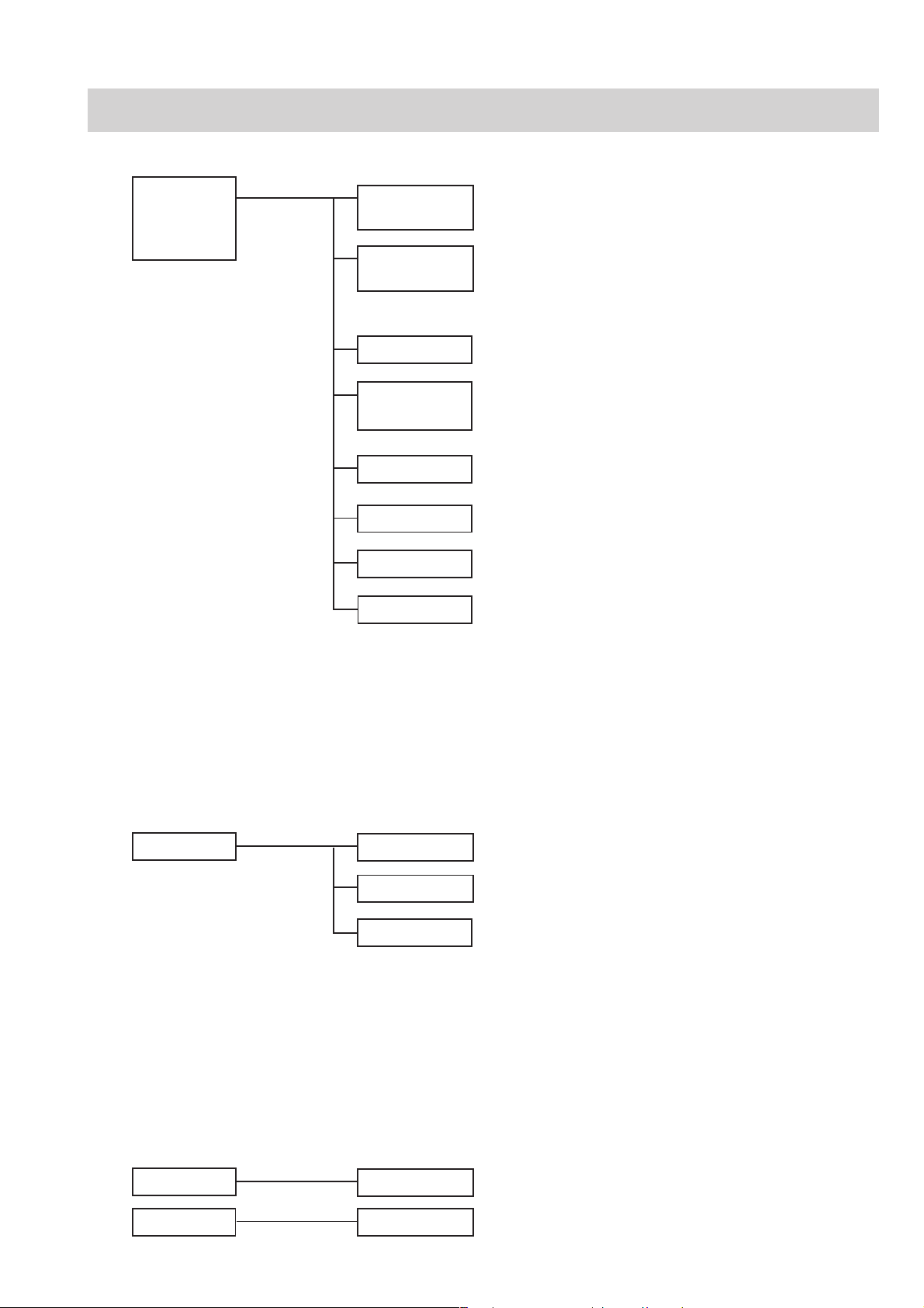
Service Manual BSM-2300 1.13
BSM-2301A
BSM-2301K
BSM-2303K
BSM-2304A
UR-3610
MAIN Board
Chassis for BSM-2301A/K and BSM-2303K
Chassis for BSM-2304A
CD-230P
CD-232P
Power Supply Block for BSM-2301A/K and BSM-2303K
Power Supply Block for BSM-2304A
SC-040R
SC-046R
UR-3612
UR-3712
Analog Board for BSM-2301A/K and BSM-2303K
Analog Board for BSM-2304A
UR-3611
Alarm Indicator Board
UR-3643*
1
NIBP & Hall Sensor Boards
UR-3644*
1
Operation & Power SW Boards
Composition
*
1
Refer to Section 8 “Replaceable Parts List”.
*
2
BSM-2301A/K has no UR-3681 IBP board
UR-3681*
1
*
2
IBP Board
WS-231P
REC MAIN Board
UR-3615
REC Key & Power Boards
UR-3616*
RG-922P
Recorder Unit
Recorder Module (option)
* Refer to “Optional Recorder Module WS-231P” in Section 8.
IO ANALOG OUT Board
UR-3691
Interface (option)
(Power supply unit* included)
IO CT OUT Board
UR-3731QI-236P
QI-231P
1. GENERAL
1.14 Service Manual BSM-2300
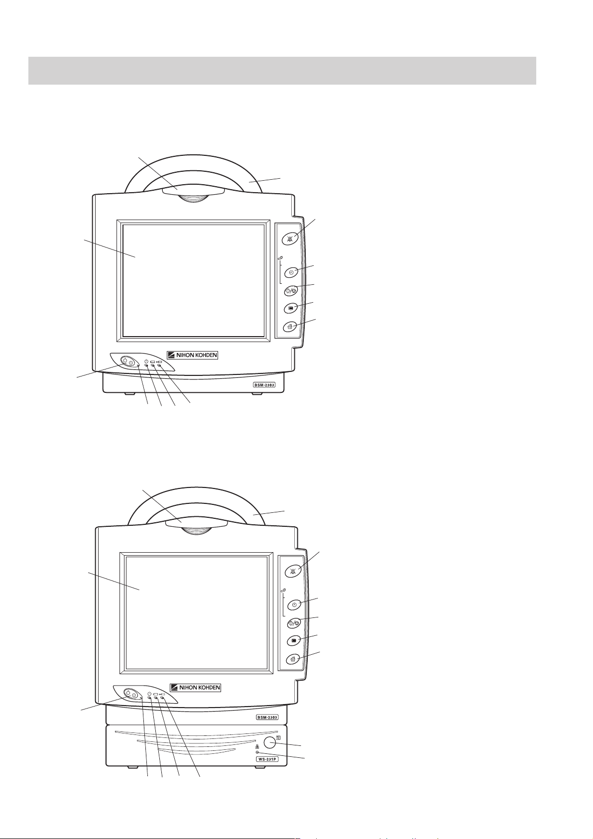
Panel Descriptions
Front Panel
SILENCE
ALARMS
NIBP
INTERVAL
START/STOP
MENU
HOME
1
2
3
4
5
6
7
8
9
10
11
12
13
1
2
3
4
5
6
7
8
9
10
11
12
13
SILENCE
ALARMS
NIBP
INTERVAL
START/STOP
MENU
HOME
14
15
With optional WS-231P recorder module
Without optional WS-231P recorder module
Loading...