


Life Scope i
BEDSIDE MONITOR
BSM-2301A/2304A
Life Scope L
BEDSIDE MONITOR
BSM-2351A
0614-006206H

Model: BSM-2301A/2304A/2351A
Manual code no.: 0614-006206H
We welcome your comments about this manual. Your comments and suggestions help us improve
our manuals. Please circle the number for each of the following statements corresponding to your
evaluation and add comments in the space provided.
Fax or send your completed comment card to:
Fax: +81 (3) 5996-8100
International Div., Sales Promotion Section, Nihon Kohden Corp., 1-31-4, Nishiochiai Shinjuku-ku,
Tokyo 161-8560, Japan
This manual is organized. 1 2 3 4 5
I can find the information I want. 1 2 3 4 5
The information is accurate. 1 2 3 4 5
I can understand the instructions. 1 2 3 4 5
The illustrations are appropriate and helpful. 1 2 3 4 5
cutting line
The manual length is appropriate. 1 2 3 4 5
Reader Comment Card
Strongly Agree Neutral Disagree Strongly
Agree Disagree
Comments:
Thank you for your cooperation. We appreciate it very much.
Name:
Occupation/Position:
Hospital/Company:
Address:
Phone:

CONTENTS
Contents
GENERAL HANDLING PRECAUTIONS ......................................................................... i
WARRANTY POLICY .................................................................................................... ii
EMC RELATED CAUTION ............................................................................................ iii
Conventions Used in this Manual and Instrument ......................................................... v
Warnings, Cautions and Notes ............................................................................v
Explanations of the Symbols in this Manual and Instrument.............................. vi
On panels .......................................................................................................... vi
On screen ......................................................................................................... vii
Others ............................................................................................................... vii
Section 1 General .................................................................................. 1C.1
Introduction .......................................................................................................................... 1.1
Features ............................................................................................................................... 1.2
Composition ......................................................................................................................... 1.4
Network Composition ........................................................................................................... 1.6
Panel Description ................................................................................................................. 1.7
Front Panel ................................................................................................................. 1.7
Left Side Panel ...........................................................................................................1.8
BSM-2301/2351 ............................................................................................... 1.8
BSM-2304 ........................................................................................................ 1.9
Right Side Panel.......................................................................................................1.10
Basic Operating Concepts .................................................................................................. 1.12
Screen Displays .......................................................................................................1.12
Using Touch Screen Keys......................................................................................... 1.16
Keys on the Front Panel ........................................................................................... 1.18
Using the MENU Window ......................................................................................... 1.18
General Safety Information ................................................................................................ 1.19
General ..................................................................................................................... 1.19
Installation ............................................................................................................... 1.20
Using QI-231P/236P Interface ................................................................................. 1.21
Using DZ-230P Hooks ..............................................................................................1.22
Network .................................................................................................................... 1.22
Battery ..................................................................................................................... 1.23
ECG Monitoring ........................................................................................................1.24
Respiration Monitoring .............................................................................................. 1.26
SpO2 Monitoring ....................................................................................................... 1.26
NIBP Monitoring .......................................................................................................1.29
IBP Monitoring ......................................................................................................... 1.30
Temperature Monitoring ............................................................................................ 1.31
CO2 Monitoring ......................................................................................................... 1.31
Maintenance ............................................................................................................ 1.34
Operator's Manual BSM-2300A C.1

CONTENTS
Section 2 Preparations ......................................................................... 2C.1
Preparation Flowchart .......................................................................................................... 2.1
Installation Conditions ..........................................................................................................2.2
Preparing the Optional Recorder Module .............................................................................. 2.4
Installing the Recorder Module ...................................................................................2.4
Loading the Recording Paper......................................................................................2.4
Attaching the Optional Hooks ............................................................................................... 2.6
Connecting an External Instrument to the Monitor ................................................................2.7
Connecting the Monitor to a Network .................................................................................... 2.8
Inserting the Network Card or Network Printer Card ................................................... 2.9
Removing the Network Card or Network Printer Card ............................................... 2.11
Using the QI-210P Wireless LAN station .................................................................. 2.11
Power ................................................................................................................................. 2.12
AC or Battery Power Source Selection .....................................................................2.12
Connecting the Power Cord and Grounding the Monitor ............................................ 2.12
Connecting the Power Cord ............................................................................ 2.12
Grounding the Monitor .................................................................................... 2.13
Turning the Monitor On ............................................................................................. 2.13
Check Before Turning On the Monitor ............................................................. 2.13
Turning the Monitor On ................................................................................... 2.14
Standby Mode ................................................................................................ 2.15
Check After Turning On the Monitor and During Monitoring ............................ 2.15
Turning the Monitor Off ............................................................................................. 2.16
Check After/Before Turning the Monitor Off .................................................... 2.16
Power and Battery Status Indications ...................................................................... 2.16
Battery Handling and Operation ................................................................................ 2.17
Safety Information.......................................................................................... 2.17
Battery Lifetime.............................................................................................. 2.19
Battery Handling Procedures ......................................................................... 2.19
When Using a Battery for the First Time or After Storage .............................. 2.19
When Not Using the Monitor or Battery ..........................................................2.19
When the BATTERY WEAK Message Appears .............................................. 2.20
Installing or Replacing the Battery ................................................................. 2.20
Charging the Battery ...................................................................................... 2.20
Disposal of Battery Pack................................................................................2.21
Section 3 Changing System Setup Settings ...................................... 3C.1
Displaying the SYSTEM SETUP Screen ............................................................................. 3.2
Changing Settings ......................................................................................................3.3
Closing the SYSTEM SETUP Screen and Displaying the Monitoring Screen ............ 3.3
List and Explanation of the SYSTEM SETUP Settings ........................................................ 3.4
List of All Settings ...................................................................................................... 3.4
Site Setting (SITE) .....................................................................................................3.6
Display Settings (DISPLAY SETUP) .......................................................................... 3.7
Bed ID Setting (BED ID SETUP) ............................................................................... 3.8
Parameter and Other Settings (PARAMETER SETUP) .............................................. 3.9
Alarm Settings (ALARM SETUP) .............................................................................3.10
Unit Settings (UNITS SETUP) ................................................................................. 3.14
C.2 Operator's Manual BSM-2300A

CONTENTS
Color Settings (COLOR SETUP) .............................................................................. 3.15
Recording Settings (RECORD SETUP) ....................................................................3.18
Other Settings (OTHER SETUP) .............................................................................. 3.19
Alarm Master Settings (ALARM MASTER) .............................................................. 3.20
Arrhythmia Recall Master Settings (ARRHYTHMIA RECALL MASTER) ................. 3.22
Network Settings (NETWORK SETUP) ....................................................................3.23
Network Printer Settings (PRINTER SETUP) ........................................................... 3.24
External Interface Information (EXT I/F SETUP) ..................................................... 3.26
Initializing the System ........................................................................................................3.27
Section 4 Necessary Settings Before Monitoring ............................. 4C.1
Changing Date and Time ...................................................................................................... 4.1
Changing Sound Settings ..................................................................................................... 4.3
Changing the Screen Brightness .......................................................................................... 4.5
Assigning a Function to the Function Keys .......................................................................... 4.6
Entering Patient Name..........................................................................................................4.8
Displaying the PATIENT INFO Window ....................................................................... 4.9
Entering the Patient Name Using the Keyboard ........................................................4.10
Entering the Patient Name Using Free Function ....................................................... 4.11
Entering the Patient ID ............................................................................................. 4.12
Deleting Data...................................................................................................................... 4.13
Section 5 Monitoring Screen ............................................................... 5C.1
Safety Precautions for Monitoring ........................................................................................ 5.2
Using an Electrosurgery Unit ........................................................................... 5.2
Using a Defibrillator ..........................................................................................5.2
Overview .............................................................................................................................. 5.3
Monitoring Screen ...................................................................................................... 5.3
Review Windows ........................................................................................................ 5.3
Sync Sound ............................................................................................................... 5.4
Adjusting the Sync and Alarm Sound Volume ............................................................ 5.4
Changing Settings and Performing Other Tasks During Monitoring .............................5.4
Interbed Monitoring .....................................................................................................5.4
Monitoring Screen ................................................................................................................ 5.5
Settings for the Monitoring Screen .............................................................................5.6
Waveform Sweep Mode and Speed..................................................................5.6
Trendgraph/PWTT trendgraph/OCRG Display on the Monitoring Screen
On or Off .......................................................................................................... 5.6
Background and Parameter Colors ................................................................... 5.7
Waveform Sensitivity ....................................................................................... 5.7
Displaying Other Windows from the Monitoring Screen .............................................. 5.8
Changing Settings for Monitoring Screen ............................................................................. 5.9
Displaying OCRG ...............................................................................................................5.11
Displaying PWTT Trendgraph ............................................................................................. 5.12
Freezing Waveforms ........................................................................................................... 5.13
Using Sleep Mode .............................................................................................................. 5.14
Turning Sleep Mode On .................................................................................. 5.14
Turning Sleep Mode Off .................................................................................. 5.15
Operator's Manual BSM-2300A C.3

CONTENTS
Displaying the Large Numeric Window ................................................................................5.16
Section 6 Alarm Function ..................................................................... 6C.1
Overview of Alarms .............................................................................................................. 6.2
What is an Alarm........................................................................................................6.2
Alarm Level ................................................................................................................6.2
Alarm Priority ............................................................................................................. 6.3
Silencing an Alarm/Suspending Alarms......................................................................6.3
Alarm Master ............................................................................................................. 6.3
Automatic Recording ..................................................................................................6.4
Alarm Setting ............................................................................................................. 6.4
Adjusting Alarm Sound Volume ..................................................................................6.4
Standby Mode ............................................................................................................6.4
Alarm History Window ................................................................................................ 6.5
Interbed Alarm ............................................................................................................6.5
Alarm Types ......................................................................................................................... 6.6
Vital Signs Alarms .....................................................................................................6.6
Arrhythmia Alarms .....................................................................................................6.6
Parameter Alarms ...................................................................................................... 6.7
ECG Related Alarms ........................................................................................6.7
Respiration Related Alarms ..............................................................................6.7
SpO2 Related Alarms ....................................................................................... 6.7
NIBP Related Alarms .......................................................................................6.7
IBP Related Alarms .........................................................................................6.7
CO2 Related Alarms ......................................................................................... 6.8
Temperature Related Alarms ............................................................................ 6.8
Other Alarms .............................................................................................................. 6.8
Messages...................................................................................................................6.8
ECG Related Messages ................................................................................... 6.8
Respiration Related Messages.........................................................................6.8
SpO2 Related Messages .................................................................................. 6.9
NIBP Related Messages ..................................................................................6.9
IBP Related Message ...................................................................................... 6.9
Temperature Related Message ......................................................................... 6.9
CO2 Related Messages .................................................................................. 6.10
Other Messages ............................................................................................ 6.10
INTERBED ALARM message ........................................................................ 6.10
Alarm Indications ............................................................................................................... 6.11
Overview .................................................................................................................. 6.11
Individual Alarm Indications ..................................................................................... 6.11
Vital Signs Alarms ......................................................................................... 6.11
Arrhythmia Alarms ......................................................................................... 6.13
Parameter Alarms .......................................................................................... 6.13
Other Alarms.................................................................................................. 6.15
Alarm Control Marks ................................................................................................ 6.16
Alarm Silence Mark ........................................................................................ 6.16
Alarm Recording Off Mark .............................................................................. 6.16
Priority of Alarm Control Marks ......................................................................6.16
C.4 Operator's Manual BSM-2300A

CONTENTS
Individual Vital Signs Alarm Setting Indication ............................................... 6.16
Adjusting the Alarm Sound Volume .......................................................................... 6.16
Silencing/Suspending Alarms ............................................................................................. 6.17
Overview .................................................................................................................. 6.17
Silencing Alarms After Alarm Occurrence ................................................................ 6.18
Silencing Alarm .............................................................................................. 6.18
Canceling Alarm Silence ................................................................................ 6.18
Suspending Alarms Before Alarm Occurrence ......................................................... 6.18
Suspending Alarms for Two Minutes .............................................................. 6.18
Suspending All Alarms and NIBP STAT and Automatic Measurements
Indefinitely ..................................................................................................... 6.19
Suspending All Alarms Indefinitely ................................................................. 6.21
Turning Automatic Alarm Recording On/Off ........................................................................6.23
Setting Alarm ..................................................................................................................... 6.25
Overview .................................................................................................................. 6.25
Alarm Limits Ranges ................................................................................................ 6.25
Vital Signs Alarms ......................................................................................... 6.25
Arrhythmia Alarms ......................................................................................... 6.26
Setting Vital Signs Alarm Individually ....................................................................... 6.27
Setting All Vital Signs Alarms to a Preset Pattern (Alarm Master) ........................... 6.28
Setting Arrhythmia Alarms Individually ..................................................................... 6.29
Setting All Arrhythmia Alarms to a Preset Pattern (Alarm Master) ........................... 6.30
Section 7 Review Windows .................................................................. 7C.1
General ................................................................................................................................. 7.1
Trend Window ....................................................................................................................... 7.2
Overview .................................................................................................................... 7.2
Displaying the TREND Window...................................................................................7.3
Changing the Time Threshold for Apnea Trendgraph ................................................... 7.5
Recording the Trendgraph ........................................................................................... 7.6
Printing the Trendgraph ............................................................................................... 7.6
List Window .......................................................................................................................... 7.8
Overview .................................................................................................................... 7.8
Displaying the LIST Window ....................................................................................... 7.9
Setting the Data Sampling Interval for the Periodic Vital Signs List ......................... 7.10
Selecting Parameters to be Displayed on the LIST Window ..................................... 7.11
Recording the List .................................................................................................... 7.12
Printing the List ........................................................................................................7.12
Arrhythmia Recall Window ..................................................................................................7.14
Overview .................................................................................................................. 7.14
Arrhythmia List ............................................................................................... 7.14
Arrhythmia Waveform Annotation ................................................................... 7.15
Displaying the Arrhythmia Recall Window ................................................................. 7.15
Recording the Arrhythmia Recall Waveform ............................................................. 7.16
Printing the Arrhythmia Recall Waveform ................................................................. 7.17
Selecting the Arrhythmia Types to be Saved as a Recall File .................................. 7.19
Alarm History Window ........................................................................................................ 7.20
Displaying the ALARM HISTORY Window ................................................................ 7.20
Recording the Alarm History Data ............................................................................ 7.21
Operator's Manual BSM-2300A C.5

CONTENTS
Section 8 Recording ............................................................................. 8C.1
Overview of Recording ......................................................................................................... 8.1
Recording Modes ....................................................................................................... 8.2
Manual Recording/Printing on the Monitoring Screen (Real Time/Delayed
Recording) ........................................................................................................8.3
Manually Recording OCRG on the Monitoring Screen ......................................8.3
Manually Recording PWTT trendgraph on the Monitoring Screen.....................8.3
Manually Recording/Printing on the Review Windows ...................................... 8.3
Periodic Recording ........................................................................................... 8.3
Alarm Recording .............................................................................................. 8.4
Recording Mode Annotations .....................................................................................8.5
Recording Priority ....................................................................................................... 8.6
Recording Sensitivity ................................................................................................. 8.6
Recording Speed ........................................................................................................8.6
Recording Related Message ...................................................................................... 8.6
Recorded/Printed Data ............................................................................................... 8.7
Changing the Recording Pattern ........................................................................................... 8.8
Changing the Recording Sweep Speed .................................................................................8.9
Manually Recording/Printing Waveforms.............................................................................8.10
Recording Waveforms on the Optional Recorder ...................................................... 8.10
Recording OCRG on the Optional Recorder .............................................................. 8.10
Recording PWTT Trendgraph on the Optional Recorder ............................................ 8.10
Manual Printing on the Network Printer .................................................................... 8.11
Setting Periodic Recording ................................................................................................. 8.12
Changing Settings for Automatic Periodic Recording ............................................... 8.13
Printing on a Network Printer .............................................................................................. 8.14
Section 9 Interbed Window................................................................... 9C.1
Registering Interbed Beds .................................................................................................... 9.2
Removing an Interbed Bed ...............................................................................9.3
Displaying the Interbed Bed Data .........................................................................................9.4
Interbed Alarm ...................................................................................................................... 9.6
Setting Interbed Alarm On or Off......................................................................9.6
Section 10 ECG Monitoring .................................................................. 10C.1
General ............................................................................................................................... 10.1
Preparing for ECG Monitoring ............................................................................................. 10.2
Preparation Flowchart .............................................................................................. 10.2
Selecting a Lead ...................................................................................................... 10.2
Number of Electrodes and Measuring Leads ............................................................10.3
Electrode Position .................................................................................................... 10.3
3 Electrode Leads .......................................................................................... 10.3
6 Electrode Leads .......................................................................................... 10.4
Selecting Electrodes and Lead ................................................................................. 10.5
Types of Leads and Connection Cord ............................................................. 10.5
Connecting Cables and Attaching Disposable Electrodes ........................................ 10.6
Connecting the Electrode Cable to the Monitor .............................................. 10.6
C.6 Operator's Manual BSM-2300A

CONTENTS
Attaching Disposable Electrodes to the Patient ............................................. 10.7
Monitoring ECG .................................................................................................................. 10.8
ECG Information on the Monitoring Screen ..............................................................10.8
Measuring ST Level ................................................................................................. 10.9
Monitoring Arrhythmia ............................................................................................ 10.10
Arrhythmia Analysis Classification Messages ............................................. 10.10
Turning Arrhythmia Analysis On/Off ............................................................. 10.11
Learning the ECG Waveform for Arrhythmia Detection (VPC Learning) ........ 10.12
Changing the Dominant QRS ....................................................................... 10.14
Noise Detection and Display .................................................................................. 10.15
Detached Electrode Detection and Display ............................................................ 10.16
Changing ECG Settings ................................................................................................... 10.17
Changing the Monitoring Lead ................................................................................ 10.17
Changing the ECG Sensitivity ................................................................................ 10.20
Changing the Heart Rate or Pulse Rate and ST Alarm Limits ................................ 10.21
Changing the Arrhythmia Alarm Setting.................................................................. 10.22
Changing the Type of Electrode Cable and Leads................................................... 10.24
Changing the Sync Source ..................................................................................... 10.26
Turning the Filters On/Off ....................................................................................... 10.27
Selecting the Mode for Updating the Heart Rate .................................................... 10.29
Turning Pacing Spike Detection On/Off .................................................................. 10.30
Displaying the Pacing Mark on the ECG ................................................................ 10.32
Use with an Electrosurgical Unit ....................................................................................... 10.33
Section 11 Respiration Monitoring...................................................... 11C.1
General ............................................................................................................................... 11.1
Measurement Method ............................................................................................... 11.1
Impedance Method ........................................................................................ 11.1
Thermistor Method ......................................................................................... 11.2
Preparing for Respiration Monitoring in Impedance Method ................................................ 11.3
Preparation Flowchart .............................................................................................. 11.3
Electrode Position and Waveform Examples ............................................................11.4
Connecting Cables and Attaching Disposable Electrodes ........................................ 11.6
Preparing for Respiration Monitoring in Thermistor Method ................................................ 11.7
Preparation Flowchart .............................................................................................. 11.7
Respiration Pickups ................................................................................................. 11.7
Connecting the Cable to the Monitor ........................................................................ 11.8
Attaching the Respiration Pickup ............................................................................. 11.8
When Using Respiration Pickup for Airway ....................................................11.8
When Using Respiration Pickup for Nose ....................................................... 11.9
Monitoring Respiration ...................................................................................................... 11.10
Respiration Information on the Monitoring Screen .................................................. 11.10
Changing Respiration Settings ......................................................................................... 11.12
Turning Respiration Monitoring On or Off in Impedance Method ............................. 11.12
Changing the Monitoring Lead in Impedance Method ............................................. 11.14
Changing the Respiration Sensitivity ...................................................................... 11.15
Changing the Respiration Waveform Sweep Speed ................................................ 11.16
Changing the Apnea Alarm Limit ............................................................................ 11.17
Operator's Manual BSM-2300A C.7

CONTENTS
Changing the Respiration Alarm Limits ................................................................... 11.18
Section 12 SpO2 Monitoring ................................................................. 12C.1
General ............................................................................................................................... 12.1
Preparing for SpO2 Monitoring ............................................................................................ 12.2
Preparation Flowchart .............................................................................................. 12.2
Selecting a Probe ..................................................................................................... 12.3
Nihon Kohden Reusable Probes .....................................................................12.3
Nihon Kohden Disposable Probes .................................................................. 12.4
Nellcor SpO2 Probes ...................................................................................... 12.5
Connecting Cables ................................................................................................... 12.6
Connecting Cable to the Monitor .................................................................... 12.6
Attaching the Probe to the Patient............................................................................12.7
Monitoring SpO2................................................................................................................. 12.9
SpO2 Information on the Monitoring Screen ............................................................ 12.10
Detection and Display of Measurement Condition .................................................. 12.11
CHECK PROBE Message (When the Finger Probe is Used) ....................... 12.11
DETECTING PULSE Message .................................................................... 12.11
M Message .................................................................................................. 12.11
Changing SpO2 Settings .................................................................................................. 12.12
Changing the Pulse Waveform Sensitivity .............................................................. 12.12
Changing the SpO2 Alarm Limits ............................................................................ 12.14
Changing the Sync Source ..................................................................................... 12.15
Selecting Sync Sound Pitch .................................................................................. 12.16
Selecting the Response Mode ............................................................................... 12.18
Section 13 NIBP Monitoring ................................................................. 13C.1
General ............................................................................................................................... 13.1
Oscillometric Method ..................................................................................... 13.1
Measurement Modes......................................................................................13.1
Preparing for NIBP Measurement .......................................................................................13.2
Preparation Flowchart .............................................................................................. 13.2
Selecting the Cuff .................................................................................................... 13.2
Cuff Width and Arm Circumference ................................................................ 13.3
Types of Cuffs .......................................................................................................... 13.4
Reusable Cuffs .............................................................................................. 13.4
Disposable Cuffs ............................................................................................ 13.6
Disinfecting Disposable Cuffs before Use ......................................................13.7
Connecting Cables and Attaching the Cuff to the Patient......................................... 13.7
Connecting Air Hose and Cuff to the Monitor ................................................. 13.7
Attaching the Cuff to the Patient ....................................................................13.9
Changing NIBP Settings ................................................................................................... 13.11
Selecting the Initial Cuff Inflation Pressure ............................................................ 13.11
Selecting the Measurement Mode and Interval ...................................................... 13.13
Selecting the Measurement Modes for the Mode Selection by the NIBP
INTERVAL Key............................................................................................. 13.14
Measurement Modes.................................................................................... 13.16
C.8 Operator's Manual BSM-2300A

CONTENTS
Changing the NIBP Alarm Settings ........................................................................ 13.19
Changing the PWTT Settings ................................................................................. 13.20
Measuring and Monitoring NIBP ....................................................................................... 13.22
Recommended Patient State.................................................................................. 13.22
Starting and Stopping NIBP Measurement ............................................................. 13.23
Manual Mode ............................................................................................... 13.23
STAT (Continuous) Mode .............................................................................. 13.23
Auto Mode ................................................................................................... 13.23
NIBP Information on the Monitoring Screen ........................................................... 13.24
Dimming and Hiding the NIBP Data ............................................................. 13.24
Section 14 IBP Monitoring .................................................................... 14C.1
General ............................................................................................................................... 14.1
Preparing for Blood Pressure Monitoring ............................................................................ 14.2
Preparation Flowchart .............................................................................................. 14.2
Selecting the Blood Pressure Measuring Device ...................................................... 14.2
Blood Pressure Transducers ........................................................................... 14.3
IBP Connection Cords .................................................................................... 14.4
Installing the Blood Pressure Measuring Device ...................................................... 14.5
Connecting Cables to the Monitor .................................................................. 14.5
Assembling the Infusion Circuit ..................................................................... 14.6
Connecting the Dome to the Infusion Circuit .................................................. 14.7
Connecting the Blood Pressure Transducer to the Dome ................................ 14.8
Adjusting Zero Balance ............................................................................................ 14.9
Adjusting Zero Balance .................................................................................. 14.9
Monitoring IBP ................................................................................................................. 14.12
IBP Information on the Monitoring Screen ............................................................. 14.12
Changing IBP Settings ..................................................................................................... 14.13
Changing the IBP Alarm Limits .............................................................................. 14.13
Changing the IBP Scale ......................................................................................... 14.14
Changing the Sync Source ..................................................................................... 14.16
Selecting Sync Sound Pitch .................................................................................. 14.17
Selecting the Mode for Calculating IBP .................................................................. 14.19
Selecting the Data Display Mode ........................................................................... 14.20
Changing the IBP Waveform Display Mode ............................................................ 14.21
Changing the Label ................................................................................................. 14.23
Types of Labels ............................................................................................ 14.23
Changing the Labels ..................................................................................... 14.23
Section 15 CO2 Monitoring ................................................................... 15C.1
General ............................................................................................................................... 15.1
Mainstream Method.................................................................................................. 15.1
Measurement Error with the TG-900P/TG-920P CO2 Sensor Kit .............................. 15.2
Preparing for CO2 Monitoring .............................................................................................. 15.4
Preparation Flowchart .............................................................................................. 15.4
Types of CO2 Sensor Kit .......................................................................................... 15.4
Using TG-900P CO2 Sensor Kit ................................................................................ 15.4
Operator's Manual BSM-2300A C.9

CONTENTS
Connecting the CO
Connecting the CO2 Adapter to the Respiration Circuit ................................... 15.5
Using TG-950P CO2 Sensor Kit ................................................................................ 15.6
Connecting the CO2 Sensor Kit to the Monitor ............................................... 15.7
Connecting the CO2 Adapter to the Respiration Circuit ................................... 15.7
Performing Zero Calibration ............................................................................15.8
Using TG-920P CO2 Sensor Kit .............................................................................. 15.11
Connecting CO2 Sensor Kit to the Monitor ................................................... 15.12
Attaching the CO2 Sensor Kit to the Patient................................................. 15.12
Monitoring CO2................................................................................................................. 15.13
CO2 Information on the Monitoring Screen ............................................................. 15.14
Changing CO2 Settings..................................................................................................... 15.15
Changing the Respiration Alarm Limits ................................................................... 15.15
Changing the Apnea Alarm Limit ............................................................................ 15.16
Changing the EtCO2 Alarm Limits .......................................................................... 15.17
Changing the FiCO2 Alarm Limits ........................................................................... 15.18
Changing the CO2 Scale ......................................................................................... 15.20
Changing the CO2 Waveform Sweep Speed............................................................ 15.21
Setting the Inspiration Composition ........................................................................ 15.22
Inspection of Measuring Accuracy ................................................................................... 15.24
Daily Inspection of Measuring Accuracy ................................................................ 15.24
Inspection of Measuring Accuracy (Precise Method) ............................................. 15.24
Checking Procedure ..................................................................................... 15.25
Sensor Kit to the Monitor ............................................... 15.5
2
Section 16 Temperature Monitoring.................................................... 16C.1
General ............................................................................................................................... 16.1
Preparing for Temperature Monitoring ................................................................................. 16.1
Preparation Flowchart .............................................................................................. 16.1
Selecting the Probe .................................................................................................. 16.2
Reusable Probes ............................................................................................16.2
Disposable Probe ........................................................................................... 16.3
Connecting Cables and Attaching the Probe ............................................................ 16.4
Connecting Cable to the Monitor .................................................................... 16.4
Attaching the Probe to the Patient ................................................................. 16.5
Monitoring Temperature ....................................................................................................... 16.7
Temperature Information on the Monitoring Screen .................................................. 16.7
Changing Temperature Settings .......................................................................................... 16.8
Changing the Temperature Alarm Limits ................................................................... 16.8
Section 17 Error Messages and Troubleshooting ............................. 17C.1
Monitoring .......................................................................................................................... 17.1
Messages................................................................................................................. 17.1
Problems ..................................................................................................................17.2
Network .............................................................................................................................. 17.3
Messages................................................................................................................. 17.3
Problems ..................................................................................................................17.4
Recording (When Using an Optional Recorder Module) ...................................................... 17.5
C.10 Operator's Manual BSM-2300A

CONTENTS
Messages................................................................................................................. 17.5
Problems ..................................................................................................................17.5
Printing ...............................................................................................................................17.6
Messages................................................................................................................. 17.6
Problems ..................................................................................................................17.6
ECG Monitoring .................................................................................................................. 17.7
Messages................................................................................................................. 17.7
Problems ..................................................................................................................17.8
Respiration Monitoring ........................................................................................................ 17.9
Messages................................................................................................................. 17.9
Problems in Impedance Method ...............................................................................17.9
Problems in Thermistor Method.............................................................................. 17.10
SpO
Monitoring ............................................................................................................... 17.11
2
Messages............................................................................................................... 17.11
Problems ................................................................................................................ 17.12
NIBP Monitoring ............................................................................................................... 17.13
Messages............................................................................................................... 17.13
Problems ................................................................................................................ 17.14
IBP Monitoring ................................................................................................................. 17.15
Messages............................................................................................................... 17.15
Problems ................................................................................................................ 17.15
Temperature Monitoring .................................................................................................... 17.16
Messages............................................................................................................... 17.16
Problems ................................................................................................................ 17.16
CO2 Monitoring ................................................................................................................. 17.17
Messages............................................................................................................... 17.17
Problems ................................................................................................................ 17.17
Section 18 Maintenance ....................................................................... 18C.1
Calibrating Waveforms ........................................................................................................ 18.2
Calibrating the Touch Screen .............................................................................................. 18.3
Cleaning the Touch Screen ................................................................................................. 18.5
Turning Touch Key Function On or Off ............................................................ 18.5
Cleaning the Touch Screen ............................................................................. 18.6
Handling Accessories After Use ......................................................................................... 18.7
Battery Pack ............................................................................................................ 18.7
Battery Lifetime.............................................................................................. 18.7
Replacing Battery Pack.................................................................................. 18.7
Disposal of Battery Pack................................................................................18.7
ECG and Respiration in Impedance Method .............................................................18.7
Electrode ....................................................................................................... 18.7
Disposing of Electrodes ................................................................................. 18.7
Cleaning and Disinfecting the Electrode Lead and ECG Connection Cord ...... 18.7
Respiration in Thermistor Method .............................................................................18.8
Cleaning and Disinfecting the Respiration Pickup .......................................... 18.8
SpO2......................................................................................................................... 18.8
Expiration of Nihon Kohden Disposable Probes ............................................. 18.8
Disposing of Probes .......................................................................................18.8
Cleaning and Disinfecting the SpO2 Connection Cord .................................... 18.9
Operator's Manual BSM-2300A C.11

CONTENTS
NIBP ........................................................................................................................ 18.9
NIBP Cuff Lifetime .........................................................................................18.9
Cleaning and Disinfecting the YP-950T/951T/952T/953T/954T/955T/960T/961T/
962T/963T/964T/965T Reusable Cuffs ........................................................... 18.9
Cleaning and Disinfecting the YP-900P/901P/902P/903P/904P/905P/906P
Reusable Cuffs ............................................................................................ 18.10
Cleaning and Disinfecting the Air Hose and Extension Hose ....................... 18.10
Disinfecting the Disposable Cuffs ................................................................ 18.11
Disposal of Cuffs ......................................................................................... 18.11
IBP ......................................................................................................................... 18.11
Cleaning, Disinfecting, Sterilizing and Storing the Blood Pressure
Transducer ................................................................................................... 18.11
Disposing of Transducer and Dome .............................................................. 18.13
Cleaning and Disinfecting the IBP Connection Cord ..................................... 18.14
Temperature ........................................................................................................... 18.14
Cleaning, Disinfecting and Sterilizing the Reusable Probe ........................... 18.14
Disposal of Disposable Probe ...................................................................... 18.14
CO
........................................................................................................................ 18.14
2
Cleaning and Disinfecting the Monitor .............................................................................. 18.15
Cleaning ....................................................................................................... 18.15
Disinfecting .................................................................................................. 18.15
Cleaning the Recorder Module .......................................................................................... 18.16
Cleaning the Thermal Head .......................................................................... 18.16
Cleaning the Sensors ................................................................................... 18.16
Yearly Inspection .............................................................................................................. 18.17
Clock Accuracy ................................................................................................................ 18.18
Periodical Replacement Schedule .................................................................................... 18.19
Repair Parts Availability Policy ......................................................................................... 18.19
Section 19 Reference ............................................................................ 19C.1
Factory Default Settings ..................................................................................................... 19.1
SYSTEM SETUP Screen ......................................................................................... 19.1
ECG Window ............................................................................................................ 19.1
RESP Window .......................................................................................................... 19.1
SpO2 Window ............................................................................................................ 19.2
NIBP Window ........................................................................................................... 19.2
PRESS Window ....................................................................................................... 19.2
CO2 Window .............................................................................................................. 19.3
TREND Window ........................................................................................................ 19.3
LIST Window ............................................................................................................ 19.3
ARRHYTH RECALL Window .................................................................................... 19.4
VITAL ALARM Window ............................................................................................. 19.4
ARRHYTH ALARM Window ...................................................................................... 19.5
RECORDING Window ............................................................................................... 19.5
DATE & TIME Window .............................................................................................. 19.5
SOUND & BRIGHT Window ..................................................................................... 19.5
DISPLAY Window ..................................................................................................... 19.6
FUNCTION KEY Window ......................................................................................... 19.6
INTERBED Window .................................................................................................. 19.6
C.12 Operator's Manual BSM-2300A

CONTENTS
Specifications .................................................................................................................... 19.7
Display ...........................................................................................................19.7
Sound ............................................................................................................. 19.7
Alarm ............................................................................................................. 19.7
ECG ...............................................................................................................19.7
Respiration (Transthoracic impedance pneumography) ...................................19.8
SpO
on BSM-2301/2351 ............................................................................... 19.9
2
SpO2 on BSM-2304 ........................................................................................ 19.9
Non Invasive Blood pressure, NIBP ............................................................... 19.9
Temperature ................................................................................................. 19.10
Multi-parameter Amplifier .............................................................................19.10
Invasive Blood Pressure, IBP ...................................................................... 19.10
Respiration (Thermistor method) .................................................................. 19.11
Expired Carbon Dioxide Tension, CO2........................................................... 19.11
Trendgraph ................................................................................................... 19.11
Vital Signs List ............................................................................................. 19.11
Recorder Module (optional, WS-231P) ..........................................................19.12
External Output ............................................................................................19.12
Power Requirement ...................................................................................... 19.12
Clock Accuracy............................................................................................ 19.12
Environment ................................................................................................. 19.12
Dimensions and Weight ................................................................................ 19.13
Electromagnetic Compatibility...................................................................... 19.13
Safety Standard ........................................................................................... 19.13
Input/Output Socket Pin Assignment ............................................................................... 19.14
AUX Socket ........................................................................................................... 19.14
General Requirements for Connecting Medical Electrical System .................................... 19.15
Standard Accessories ...................................................................................................... 19.17
Options and Consumables ............................................................................................... 19.18
Options for the Monitor ........................................................................................... 19.18
For ECG and Respiration (Impedance Method) Monitoring ..................................... 19.18
For Respiration Monitoring (Thermistor method) ..................................................... 19.18
For SpO2 Monitoring ............................................................................................... 19.19
For NIBP Monitoring ............................................................................................... 19.20
For IBP Measurement ............................................................................................ 19.21
For Temperature Monitoring .................................................................................... 19.23
For CO2 Monitoring (Mainstream Method) ............................................................... 19.23
For WS-231P Recorder Module .............................................................................. 19.23
Operator's Manual BSM-2300A C.13

GENERAL HANDLING PRECAUTIONS
This device is intended for use only by qualified medical personnel.
Use only Nihon Kohden approved products with this device. Use of non-approved products or in
a non-approved manner may affect the performance specifications of the device. This includes,
but is not limited to, batteries, recording paper, pens, extension cables, electrode leads, input
boxes and AC power.
Please read these precautions thoroughly before attempting to operate the instrument.
1. To safely and effectively use the instrument, its operation must be fully understood.
2. When installing or storing the instrument, take the following precautions:
(1) Avoid moisture or contact with water, extreme atmospheric pressure, excessive humidity and temperatures, poorly
ventilated areas, and dust, saline or sulphuric air.
(2) Place the instrument on an even, level floor. Avoid vibration and mechanical shock, even during transport.
(3) Avoid placing in an area where chemicals are stored or where there is danger of gas leakage.
(4) The power line source to be applied to the instrument must correspond in frequency and voltage to product
specifications, and have sufficient current capacity.
(5) Choose a room where a proper grounding facility is available.
3. Before Operation
(1) Check that the instrument is in perfect operating order.
(2) Check that the instrument is grounded properly.
(3) Check that all cords are connected properly.
(4) Pay extra attention when the instrument is combined with other instruments to avoid misdiagnosis or other
problems.
(5) All circuitry used for direct patient connection must be doubly checked.
(6) Check that battery level is acceptable and battery condition is good when using battery-operated models.
4. During Operation
(1) Both the instrument and the patient must receive continual, careful attention.
(2) Turn power off or remove electrodes and/or transducers when necessary to assure the patient’s safety.
(3) Avoid direct contact between the instrument housing and the patient.
5. To Shutdown After Use
(1) Turn power off with all controls returned to their original positions.
(2) Remove the cords gently; do not use force to remove them.
(3) Clean the instrument together with all accessories for their next use.
6. The instrument must receive expert, professional attention for maintenance and repairs. When the instrument is not
functioning properly, it should be clearly marked to avoid operation while it is out of order.
7. The instrument must not be altered or modified in any way.
8. Maintenance and Inspection:
(1) The instrument and parts must undergo regular maintenance inspection at least every 6 months.
(2) If stored for extended periods without being used, make sure prior to operation that the instrument is in perfect
operating condition.
Operator's Manual BSM-2300A i

(3) Technical information such as parts list, descriptions, calibration instructions or other information is available for
qualified user technical personnel upon request from your Nihon Kohden distributor.
9. When the instrument is used with an electrosurgical instrument, pay careful attention to the application and/or
location of electrodes and/or transducers to avoid possible burn to the patient.
10. When the instrument is used with a defibrillator, make sure that the instrument is protected against defibrillator
discharge. If not, remove patient cables and/or transducers from the instrument to avoid possible damage.
WARRANTY POLICY
Nihon Kohden Corporation (NKC) shall warrant its products against all defects in materials and workmanship for one year
from the date of delivery. However, consumable materials such as recording paper, ink, stylus and battery are excluded from
the warranty.
NKC or its authorized agents will repair or replace any products which prove to be defective during the warranty period,
provided these products are used as prescribed by the operating instructions given in the operator’s and service manuals.
No other party is authorized to make any warranty or assume liability for NKC’s products. NKC will not recognize any other
warranty, either implied or in writing. In addition, service, technical modification or any other product change performed by
someone other than NKC or its authorized agents without prior consent of NKC may be cause for voiding this warranty.
Defective products or parts must be returned to NKC or its authorized agents, along with an explanation of the failure.
Shipping costs must be pre-paid.
This warranty does not apply to products that have been modified, disassembled, reinstalled or repaired without Nihon
Kohden approval or which have been subjected to neglect or accident, damage due to accident, fire, lightning, vandalism,
water or other casualty, improper installation or application, or on which the original identification marks have been
removed.
In the USA and Canada other warranty policies may apply.
CAUTION
United States law restricts this device to sale by or on the order of physician.
ii Operator's Manual BSM-2300A

EMC RELATED CAUTION
This equipment and/or system complies with the International Standard IEC 60601-1-2 for electromagnetic
compatibility for medical electrical equipment and/or system. However, an electromagnetic environment that
exceeds the limits or levels stipulated in the IEC 60601-1-2, can cause harmful interference to the equipment
and/or system or cause the equipment and/or system to fail to perform its intended function or degrade its
intended performance. Therefore, during the operation of the equipment and/or system, if there is any
undesired deviation from its intended operational performance, you must avoid, identify and resolve the
adverse electromagnetic effect before continuing to use the equipment and/or system.
The following describes some common interference sources and remedial actions:
1. Strong electromagnetic interference from a nearby emitter source such as an authorized radio station or
cellular phone:
Install the equipment and/or system at another location if it is interfered with by an emitter source such
as an authorized radio station. Keep the emitter source such as cellular phone away from the equipment
and/or system.
2. Radio-frequency interference from other equipment through the AC power supply of the equipment and/
or system:
Identify the cause of this interference and if possible remove this interference source. If this is not
possible, use a different power supply.
3. Effect of direct or indirect electrostatic discharge:
Make sure all users and patients in contact with the equipment and/or system are free from direct or
indirect electrostatic energy before using it. A humid room can help lessen this problem.
4. Electromagnetic interference with any radio wave receiver such as radio or television:
If the equipment and/or system interferes with any radio wave receiver, locate the equipment and/or
system as far as possible from the radio wave receiver.
If the above suggested remedial actions do not solve the problem, consult your Nihon Kohden Corporation
subsidiary or distributor for additional suggestions.
This equipment complies with International Standard IEC 60601-1-2 (1993) which requires CISPR11, Group 1,
Class B. Class B EQUIPMENT is equipment suitable for use in domestic establishments and in
establishments directly connected to a low voltage power supply network which supplies buildings used for
domestic purposes.
Operator's Manual BSM-2300A iii

In IEC 60601-1-2 Medical Electronic Equipment, Part 1: General Requirements for Safety, 2. Collateral
Standard: Electromagnetic compatibility-Requirements and test. Section 36. 202. 2 Radiated radio-
frequency electromagnetic fields, PATIENT COUPLED EQUIPMENT and/or SYSTEMS applicable IMMUNITY
test methods are under consideration at SC62A/WG13. The 3 V/m IMMUNITY level may be inappropriate
especially when measuring SpO2 because physiological signals can be much smaller than those induced
by a 3 V/m electromagnetic field.
When measuring SpO2, various interference may produce false waveforms which look like pulse
waveforms. SpO2 value and pulse rate may be measured from these false waveforms, causing the alarm to
function improperly.
When installing the monitor, avoid locations where the monitor may receive strong electromagnetic
interference such as radio or TV stations, cellular phone or mobile two-way radios.
WARNING
Interaction Between Minute Ventilation Rate-Adaptive Pacemakers and Cardiac Monitoring and Diagnostic
Equipment*
The bioelectric impedance measurement sensor of a minute ventilation rate-adaptive implantable pacemaker
may be affected by cardiac monitoring and diagnostic equipment which is connected to the same patient. If
this occurs, the pacemaker may pace at its maximum rate and give incorrect data to the monitor or
diagnostic equipment. If this occurs, disconnect the monitor or diagnostic equipment from the patient or
change the setting on the pacemaker by referring to the pacemaker’s manual. For more details, contact your
pacemaker distributor or Nihon Kohden distributor.
* Minute ventilation is sensed in rate-adaptive pacemakers by a technology known as bioelectric impedance measurement
(BIM). Many medical devices in addition to pacemakers use this technology. When one of these devices is used on a
patient with an active, minute ventilation rate-adaptive pacemaker, the pacemaker may erroneously interpret the mixture
of BIM signals created in the patient, resulting in an elevated pacing rate.
For more information, see the FDA web site.
http://www.fda.gov/cdrh/safety.html
iv Operator's Manual BSM-2300A

Conventions Used in this Manual and Instrument
Warnings, Cautions and Notes
Warnings, cautions and notes are used in this manual to alert or signal the reader to specific information.
WARNING
A warning alerts the user to possible injury or death associated with the use or misuse of the instrument.
CAUTION
A caution alerts the user to possible injury or problems with the instrument associated with its use or
misuse such as instrument malfunction, instrument failure, damage to the instrument, or damage to other
property.
NOTE
A note provides specific information, in the form of recommendations, prerequirements, alternative
methods or supplemental information.
Operator's Manual BSM-2300A v
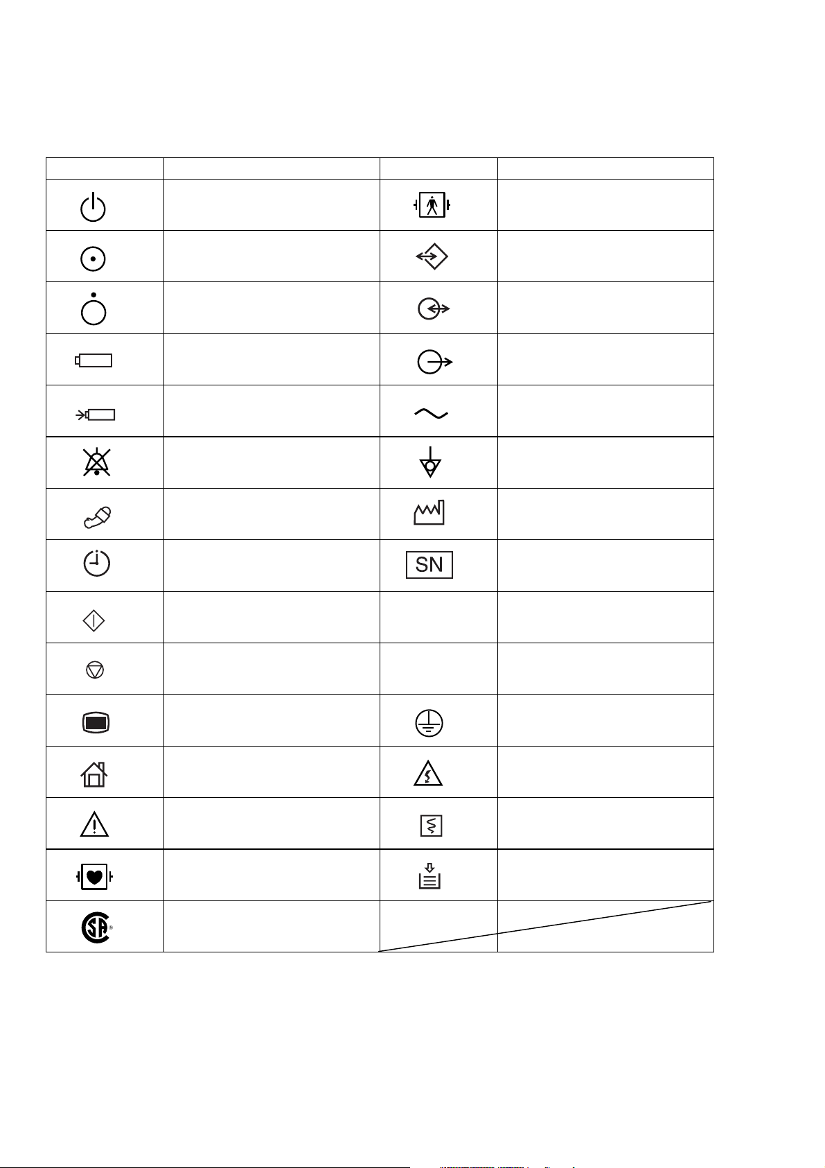
Explanations of the Symbols in this Manual and Instrument
The following symbols found in this manual/instrument bear the respective descriptions as given.
On panels
Symbol Description Symbol Description
AC operation
“On” only for a part of instrument Data input/output
“Off” only for a part of instrument Input/output terminal
Battery operation Output terminal
Battery charging Alternating current
Alarm suspend Equipotential terminal
NIBP Year of manufacture
NIBP interval Serial number
Defibrillation-proof type BF applied
part
NIBP start Splash-proof equipment
NIBP stop Watertight equipment
Menu Protective earth
Home (monitoring screen) High voltage
Attention, consult operator’s
manual
Defibrillation-proof type CF applied
part
CSA mark
IPX4
IPX7
Record start/stop (on the WS-231P
recorder module)
Out of paper (on the WS-231P
recorder module)
vi Operator's Manual BSM-2300A
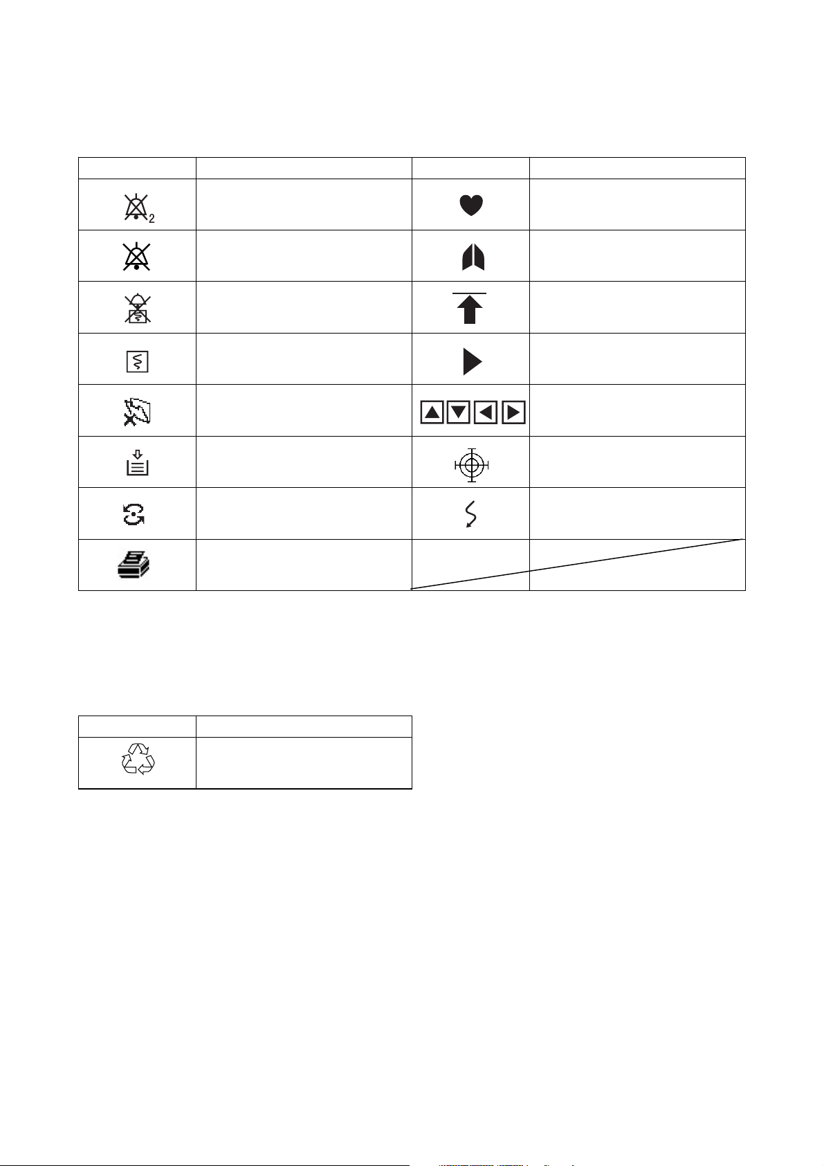
On screen
Symbol Description Symbol Description
Alarm silence with remaining
minutes
QRS/pulse sync mark
Alarm off Respiration sync mark
Alarm recording off Value out of range
Recording Current measuring value
Paper magazine open Adjust setting/Scroll data
Out of paper Touch screen calibration mark
Network communicating Waveform cascaded
Printer (when QI-111P network
printer card is used)
Others
Symbol Description
Recycle (On battery pack)
Ni-MH
Operator's Manual BSM-2300A vii

Section 1 General
Introduction ......................................................................................................................... 1.1
Features ..............................................................................................................................1.2
Composition ........................................................................................................................ 1.4
Network Composition .......................................................................................................... 1.6
Panel Description ................................................................................................................ 1.7
Front Panel ................................................................................................................ 1.7
Left Side Panel ..........................................................................................................1.8
BSM-2301/2351 .............................................................................................. 1.8
BSM-2304 ....................................................................................................... 1.9
Right Side Panel......................................................................................................1.10
Basic Operating Concepts ................................................................................................. 1.12
Screen Displays ......................................................................................................1.12
Using Touch Screen Keys........................................................................................ 1.16
Keys on the Front Panel .......................................................................................... 1.18
Using the MENU Window ........................................................................................ 1.18
General Safety Information ............................................................................................... 1.19
General .................................................................................................................... 1.19
Installation .............................................................................................................. 1.20
Using QI-231P/236P Interface ................................................................................ 1.21
Using DZ-230P Hooks .............................................................................................1.22
Network ................................................................................................................... 1.22
Battery .................................................................................................................... 1.23
ECG Monitoring .......................................................................................................1.24
Respiration Monitoring ............................................................................................. 1.26
SpO2 Monitoring ...................................................................................................... 1.26
NIBP Monitoring ......................................................................................................1.29
IBP Monitoring ........................................................................................................ 1.30
Temperature Monitoring ........................................................................................... 1.31
CO2 Monitoring ........................................................................................................ 1.31
Maintenance ........................................................................................................... 1.34
Operator's Manual BSM-2300A 1C.1

1. GENERAL
Section 1 provides a general overview of the equipment and how to operate it. If
you have not used a BSM-2300A bedside monitor before, read this section first.
• Features
• Components in the system
• Panel descriptions
• Screen displays
• Basic operation concepts
• Important safety information
Introduction
The Life Scope i BSM-2301A/2304A hardwire bedside monitor and The Life
Scope L BSM-2351A hardwire bedside monitor have several connectors for ECG,
respiration in impedance method, SpO
multi-parameter socket for IBP, respiration by thermistor method and CO
, NIBP, IBP and temperature monitoring and
2
2
monitoring. Its easy operation and compact lightweight design lets you use this
bedside monitor in the general ward, ER, RR, ICU, NICU, operating room and for
patient transportation. For portability, it can operate on battery power as well as
AC power.
For simplicity, the suffix A will be omitted in this manual. There is no difference in
operation among models with different suffixes unless otherwise specified.
NOTE
Use only Nihon Kohden parts and accessories to assure maximum
performance from your instrument.
Operator's Manual BSM-2300A 1.1

1. GENERAL
Features
• Hardwire system
BSM-2301/2351: Monitors ECG, impedance method respiration, SpO
(Nihon
2
Kohden probes), NIBP and temperature. With the multi-
parameter socket, IBP, thermistor method respiration or CO
can be monitored.
BSM-2304: Monitors ECG, impedance method respiration, SpO2 (Nellcor
probes), NIBP, IBP and temperature. With the multi-
parameter socket, IBP, thermistor method respiration or CO
can be monitored.
• AC or battery (option) operation
The monitor can operate on AC power or battery for up to 3 hours.
• Color data display
Detailed information is displayed on the wide angle, 8.4 inch color LCD (BSM-
2301/2304) or 10.4 inch color LCD (BSM-2351) . Monitoring parameters are
automatically identified.
2
2
• Easy operation by the hard keys and touch screen keys
The monitor can be operated using the touch keys on the screen, as well as the
hard keys on the panel.
• Highly reliable ECG monitoring
Arrhythmia can be analyzed and ST level can be measured. The dominant QRS
can be changed any time for template-matching analysis of arrhythmia.
• Review windows for viewing saved data
Saved data can be displayed on the trend window, list window, arrhythmia recall
window and alarm history window.
• Function keys
There are three function keys at the upper left corner of the screen. A function
can be assigned to each key, for example, freezing waveforms and displaying the
MENU window.
• Thermal array recorder with 50 mm width paper (option)
Waveforms, numeric data, trendgraphs, and vital signs lists can be recorded
manually or automatically on the optional WS-231P recorder module. Up to
three channels can be recorded.
• Central monitor connection (option)
When the optional QI-101P network card is installed in the bedside monitor, the
bedside monitor can be connected to the monitor network or any other bedside
monitor in the network. Waveforms and data of the bedside monitor can be sent
to the central monitor. An interbed data and alarm of any patient in the same
network can be displayed on the bedside monitor.
1.2 Operator’s Manual BSM-2300A

1. GENERAL
• Printing on a Network Printer (option)
When the optional QI-111P network printer card is inserted into the bedside
monitor, the data on the review windows and numeric data of the monitoring
parameters can be printed on a network printer.
• Wireless LAN system (option)
When the optional QI-210P wireless LAN station is connected to the bedside
monitor and when there are several QI-902R wireless access points installed in
the facility, the signal from the bedside monitor can be received by radio
communication with the wireless LAN access point. The wireless LAN access
point is connected to the central monitor network. For details, contact your
Nihon Kohden distributor.
• Connecting Oridion Microcap capnograph monitor (option)
With the optional QI-235P interface, Oridion Microcap capnograph monitor
can be connected to the monitor to display the data acquired by the Microcap.
For details, refer to the QI-235P interface manual.
• Anesthesia monitoring (option)
When the optional AG-920R multigas unit is connected to the monitor, the
anesthetic gas can be monitored. To connect the multigas unit, the optional YJ-
231P connection cable is required. For details, refer to the AG-920RA/RK
multigas unit manual.
Operator's Manual BSM-2300A 1.3

1. GENERAL
Composition
Bedside Monitor
BSM-2300
Interface for connecting a display and
external instruments (option)
QI-231P
Recorder Module (option)
WS-231P
Adapter for attaching
QI-231P interface (option)
DI-231P
Battery pack (option)
10HR-4/3FAUC-NK
Interface for connecting
Oridion Microcap (option)
QI-235P
Network Card (option)
QI-101P
Interface for connecting a display and
an external instrument (option)
QI-236P
Hooks (option)
DZ-230P
1.4 Operator’s Manual BSM-2300A
Wireless LAN Station (option)
QI-210P
Network Printer Card (option)
QI-111P
Cart (option)
KC-013P
BSM-2300 RGB cable (option)
YS-076P2 (10 m)
YS-080P2 (2 m)
Connection cable for optional units
YJ-231P

Multigas unit (option)
AG-920R
1. GENERAL
Operator's Manual BSM-2300A 1.5
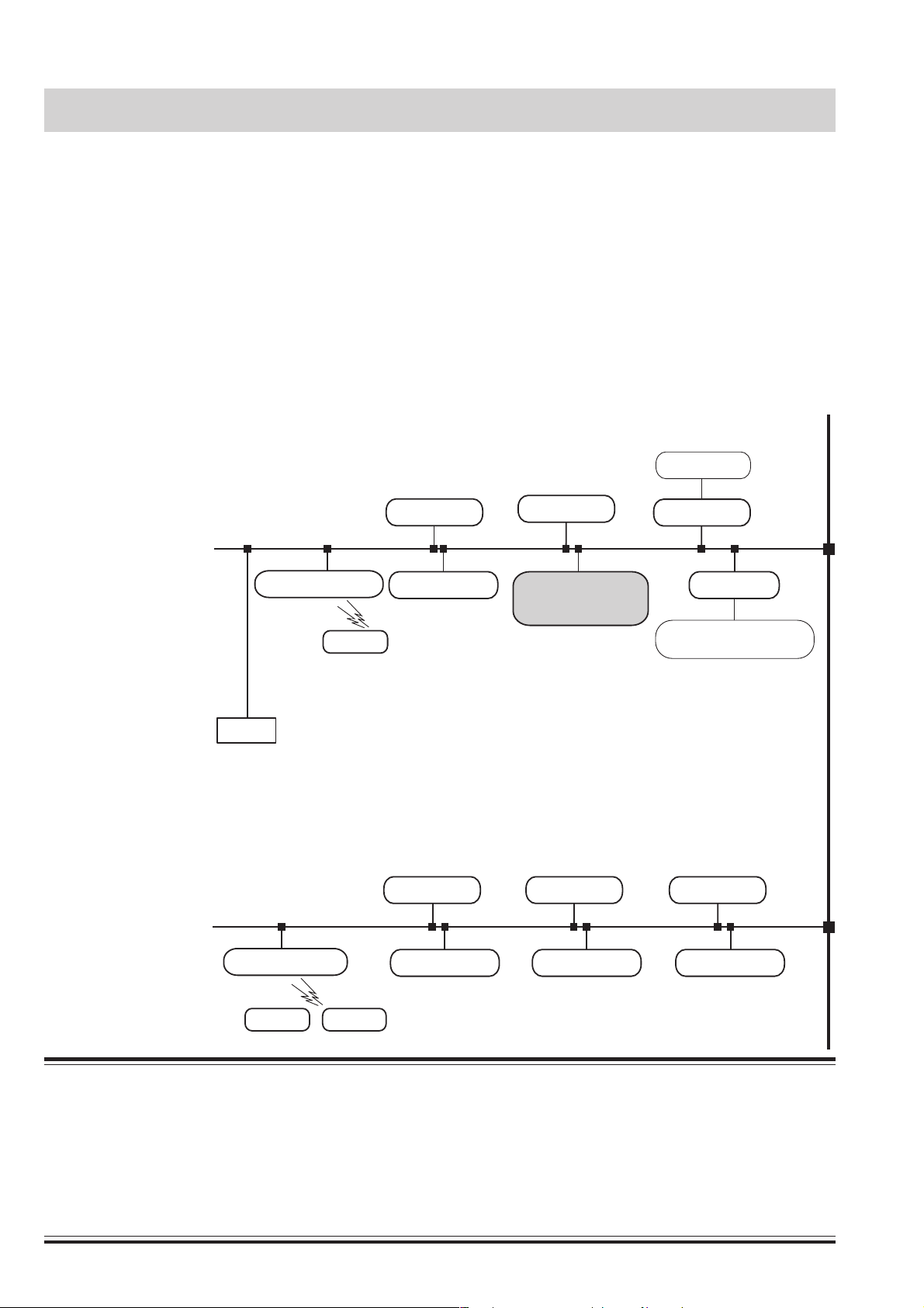
1. GENERAL
Network Composition
Network group
e.g. ICU
In a central monitor network, on a central monitor, you can see data of any bed in
the network.
The data that can be displayed on the bedside monitor or central monitor depends
on the type of bedside or central monitor used.
The number of central monitors and bedside monitors that can be connected to a
central monitor network and the network communication method depend on the
type of monitor used. For details, refer to the Network and System Installation
Guide.
Central monitors
CNS-9300 series
CNS-9701
Central monitor
CNS-9300 series
CNS-9701
Central monitor
Bedside monitors
CNS-9300 series
Central monitor
Multiple patient receiver
ORG-9200
ORG-9700
Printer
Network group
e.g. CCU
Multiple patient receiver
Transmitter
Transmitter
Bedside monitor
BSM-5100 series
BSM-4100 series
BSM-2300 series
BSM-1100 seriesTransmitter
Bedside monitor
BSM-2300
Bedside monitors/Transmitters
Central monitor
Bedside monitor
Central monitor
Bedside monitor
Interface
QI-910R
Bedside monitor
Multi-patient receiver
BSM-8000 series
ORG-8200
Central monitor
Bedside monitor
WARNING
••
• Install the printer and hubs outside the patient environment. If they are installed inside the patient
••
environment, the patient or operator may receive electrical shock.
••
• Check the software version number of the monitor before connecting it to the network. Different
••
software versions have different communication methods. When there is more than one communication
method in the network, communication may malfunction.
1.6 Operator’s Manual BSM-2300A

Panel Description
Front Panel
1. GENERAL
8
13
1
2
SILENCE
ALARMS
NIBP
INTERVAL
START/STOP
MENU
HOME
11
12
9
10
Without optional WS-231P recorder module
1
2
3
SILENCE
ALARMS
3
13
NIBP
4
5
INTERVAL
START/STOP
6
7
HOME
MENU
4
5
6
7
8
14
15
11
10
9
12
With optional WS-231P recorder module
No. Name Description
1 Alarm indicator
Red or yellow lamp blinks according to the alarm settings. Green lamp blinks
in synchronization with the patient’s QRS.
2 Handle For carrying the monitor.
3 SILENCE ALARMS key Silences the alarm sound.
4 NIBP INTERVAL key Selects NIBP measurement mode. Pressing this key changes the mode.
5 NIBPSTART/STOPkey
Starts NIBP measurement in selected mode. Pressing the key during
measurement stops measurement.
6 MENU key Displays the MENU window.
7 HOME key Closes any opened window and displays the monitoring screen.
8 Power switch Press and hold for more than one second to turn the monitor power on or off.
9 Power lamp Lights when the monitor power is turned on.
10 AC power lamp
Lights when the power cord is connected between the AC SOURCE socket
and AC outlet.
11 Battery power lamp Lights when operating on the battery power.
12 Battery charging lamp Lights or slowly blinks when charging.
13 Touch screen
Displays monitoring data. Touching a key or data on the screen changes
displaying screen and settings.
14 Record key Press to start or stop recording.
15 Out of paper lamp Blinks when out of paper. Lights when recorder door is open.
Operator's Manual BSM-2300A 1.7

1. GENERAL
Left Side Panel
BSM-2301/2351
TEMP socket
Connects to the
temperature probe
cord.
Refer to Warning and
Caution in the "General
Safety Information" section.
Multi-parameter socket
Connects to the connection cord of the parameter to
be monitored (IBP, CO
or respiration by
2
thermistor method). The type of parameter is
automatically recognized.
SpO
socket
2
Connects to the SpO2 connection cord.
ECG/RESP socket
Connects to the ECG connection cord.
Battery box
For the optional battery pack.
TEMP socket
Connects to the
temperature probe
cord.
NIBP socket
Connects to the air hose.
Without optional WS-231P recorder module
Refer to Warning and
Caution in the "General
Safety Information" section.
Multi-parameter socket
Connects to the connection cord of the parameter to
be monitored (IBP, CO
by thermistor method). The type of parameter is
automatically recognized.
SpO
socket
2
Connects to the SpO
or respiration
2
connection cord.
2
ECG/RESP socket
Connects to the ECG connection cord.
NIBP socket
Connects to the air hose.
Battery box
For the optional battery pack.
With optional WS-231P recorder module
1.8 Operator’s Manual BSM-2300A

BSM-2304
TEMP socket
Connects to the
temperature probe
cord.
PRESS 1 socket
Connects to the IBP
connection cord.
NELLCOR
OxiMax
1. GENERAL
Refer to Warning and
Caution in the "General
Safety Information" section.
Multi-parameter socket
Connects to the connection cord of the parameter to
be monitored (IBP (PRESS 2), CO
or respiration
2
by thermistor method). The type of parameter is
automatically recognized.
TM
SpO
socket
2
Connects to the SpO2 connection cord.
ECG/RESP socket
Connects to the ECG connection cord.
Battery box
For the optional battery pack.
TEMP socket
Connects to the
temperature probe
cord.
PRESS 1 socket
Connects to the IBP
connection cord.
NELLCOR
OxiMax
NIBP socket
Connects to the air hose.
Without optional WS-231P recorder module
TM
Refer to Warning and
Caution in the "General
Safety Information" section.
Multi-parameter socket
Connects to the connection cord of the parameter to
be monitored (IBP (PRESS 2), CO
or respiration
2
by thermistor method). The type of parameter is
automatically recognized.
SpO
socket
2
Connects to the SpO
connection cord.
2
ECG/RESP socket
Connects to the ECG connection cord.
NIBP socket
Connects to the air hose.
Battery box
For the optional battery pack.
With optional WS-231P recorder module
Operator's Manual BSM-2300A 1.9
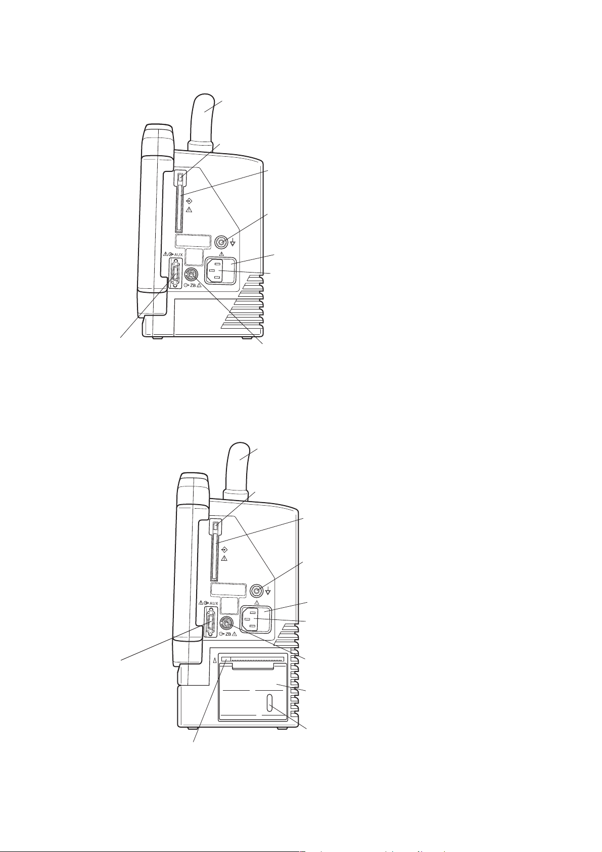
1. GENERAL
Right Side Panel
Handle
PC card eject button
PC card slot
For an optional QI-101P network card
or QI-111P network printer card.
Equipotential grounding terminal
For an equipotential grounding lead.
Fuse holder
AC SOURCE power cord socket
For the AC power cord.
AUX socket
For connecting a display monitor
or optional unit.
ZB socket
Not available.
Without optional WS-231P recorder module
Handle
PC card eject button
PC card slot
For an optional QI-101P network card
or QI-111P network printer card.
Equipotential grounding terminal
For an equipotential grounding lead.
Fuse holder
AC SOURCE power cord socket
For the AC power cord.
AUX socket
For connecting a display
monitor or optional unit.
Recorder door release lever
Pull up the lever to open the recorder door.
1.10 Operator’s Manual BSM-2300A
ZB socket
Not available.
WS-231P recorder module (option)
Paper window
For checking the amount of recording paper.
With optional WS-231P recorder module

1. GENERAL
WARNING
Connect the network as specified. Otherwise patient and
operator may get electrical shock or other injury. For connecting
the network, contact your Nihon Kohden distributor.
CAUTION
Use only the Nihon Kohden card.
WARNING
••
• For patient safety, equipotential grounding of all
••
instruments must be performed. Consult with a
qualified biomedical engineer.
••
• Only use the provided power cord. Using other
••
power cords may result in electrical shock or other
injury to the patient and operator.
CAUTION
When the provided power cord cannot be used, operate
the monitor on battery power.
WARNING
Connect only the specified instrument to the socket marked with by following the specified
procedure. Otherwise, electrical leakage current may harm the patient and operator.
CAUTION
When connecting the monitor to other instruments, the connection must comply with IEC
60601-1-1. Refer to “General Requirements for Connecting Medical Electrical System” in
Section 19.
Operator's Manual BSM-2300A 1.11
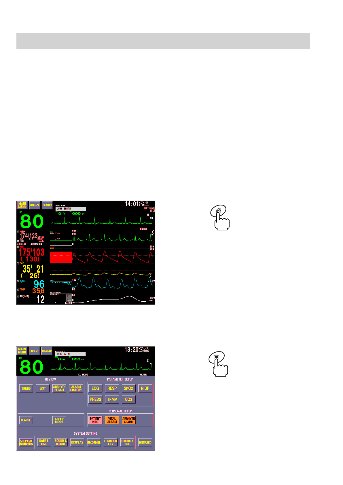
1. GENERAL
Basic Operating Concepts
Screen Displays
Monitoring screen
Following are the screens and windows available on the Life Scope i and the Life
Scope L bedside monitors. For details about the individual screens and windows,
see the appropriate section.
The shadow of the previous screen may remain for a few minutes after changing
the screen.
Normally, the monitoring screen is displayed. All screens, except for the SYSTEM
SETUP screen, return to the monitoring screen when there is no key operation for
about 3 minutes.
HOME
MENU window
• The monitoring screen can be displayed anytime by pressing
the HOME key on the front panel.
• Displays waveforms and data of the monitoring parameters.
• Touching the patient name displays the PATIENT INFO
window for entering patient name.
• Touching the parameter data displays the parameter setting
window.
MENU
The MENU window can be displayed anytime by pressing the
MENU key on the front panel. From the MENU window, you
can display any window except the monitoring screen.
1.12 Operator’s Manual BSM-2300A
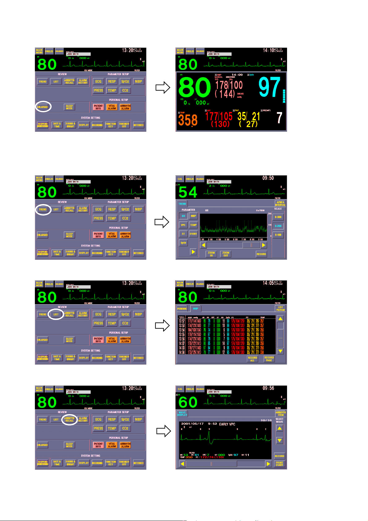
Enlarged window
Review windows
1. GENERAL
ENLARGED window
for displaying
enlarged numeric data
TREND window for
displaying 24 hour
trendgraph
LIST window for
displaying list of
parameter data
ARRHYTH
RECALL window
for displaying
arrhythmia recall file
data
Operator's Manual BSM-2300A 1.13
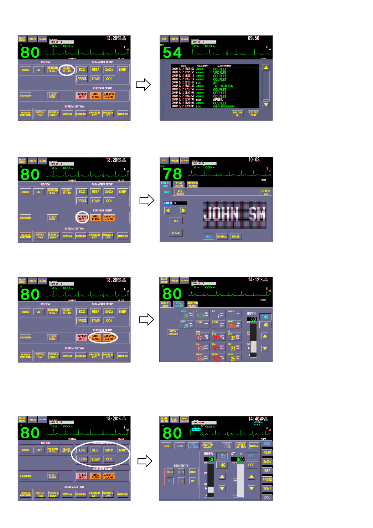
1. GENERAL
Patient information window
ALARM HISTORY
window for displaying
alarm occurrence
PATIENT INFO
window for entering
patient name. Stored
data can be deleted on
this window.
Alarm setting window
Parameter setting windows
For changing parameter monitoring settings
VITAL ALARM
window for setting
vital signs alarm and
ARRHYTH ALARM
window for setting
arrhythmia alarms
ECG window
1.14 Operator’s Manual BSM-2300A
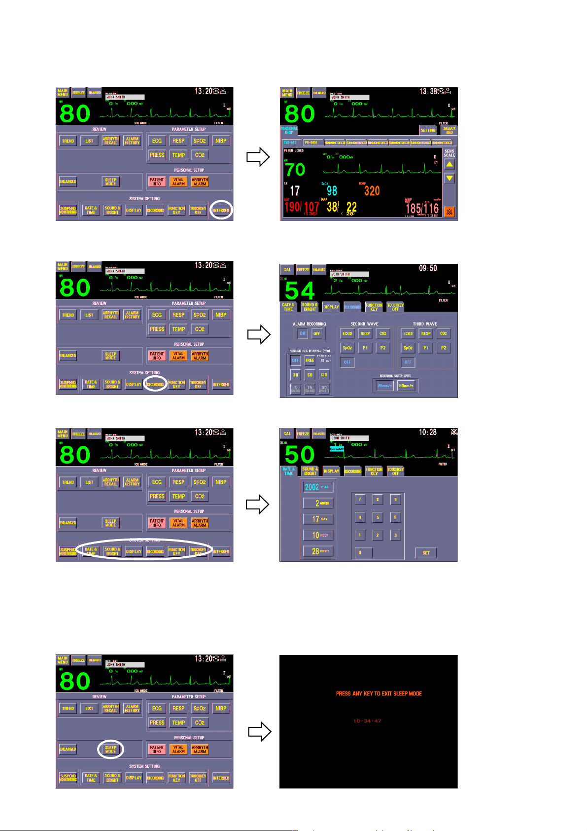
INTERBED window
For selecting interbed beds and displaying interbed bed data when the monitor is connected to a network
Setup and other windows
RECORDING window
for recording setting
1. GENERAL
DATE & TIME window for changing date and time, SOUND & BRIGHT window for changing alarm and sync sound
volume and screen brightness, DISPLAY window for changing trendgraph display on the monitoring screen and respiration/
CO2 waveform sweep speed, FUNCTION KEY window for assigning a function to a function key and TOUCHKEY OFF
window for turning touch screen function off
SLEEP MODE
window for turning
sleep mode on
Operator's Manual BSM-2300A 1.15

1. GENERAL
SYSTEM SETUP screen
SILENCE
ALARMS
For changing system settings.
Displaying the SYSTEM
SETUP screen interrupts
monitoring.
Using Touch Screen Keys
Any window can be opened and settings can be changed by touching the keys and
items on the screen with your finger or the touch pen (option).
Touching the key on the screen displays the window.
1.16 Operator’s Manual BSM-2300A
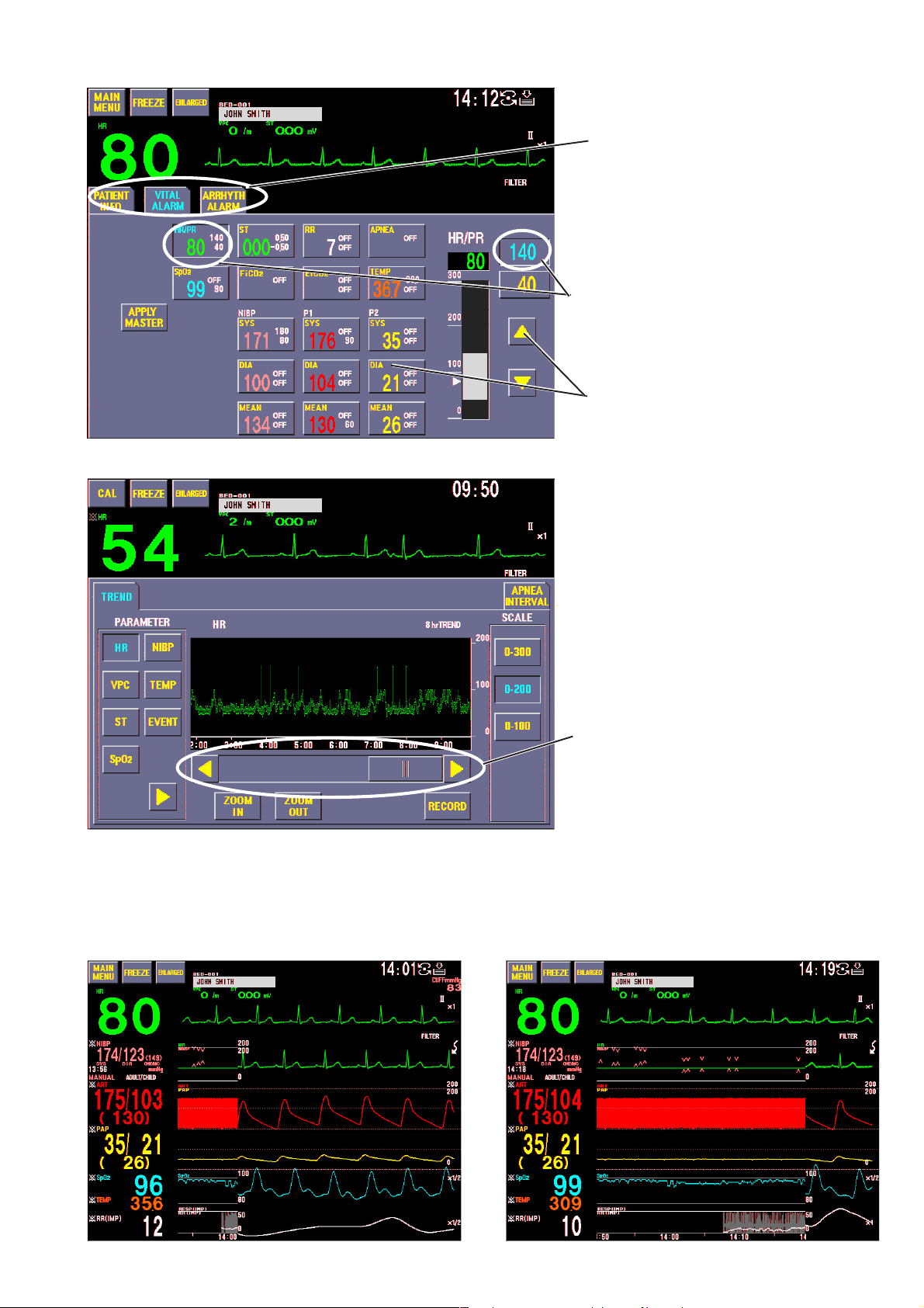
1. GENERAL
Tabs for changing displaying window. The
opened window is displayed in light blue.
Selected item is displayed in light blue
Selectable items or keys are displayed in
yellow
Scroll bar and buttons for scrolling data
The time width of the trendgraph on the monitoring screen can be adjusted by touching the position for the right edge of the
trendgraph on the screen.
Operator's Manual BSM-2300A 1.17

1. GENERAL
Keys on the Front Panel
Turns the monitor
power on or off
SILENCE
ALARMS
NIBP
INTERVAL
START/STOP
MENU
HOME
Silences alarm sound
Selects NIBP measurement mode
Starts and stops NIBP measurement
Displays the MENU window
Displays the monitoring screen
Starts and stops recording
(when using optional recorder module)
Using the MENU Window
Section 7
Section 5
Section 4
The MENU window can be displayed anytime by pressing the MENU key on the
front panel. From the MENU window, you can display any window except the
monitoring screen.
For details on each window, refer to the section specified below.
Section 14
Section 10
Section 11
Section 12
Section 13
Section 15
Section 16
Section 6
Section 6
Section 4
Section 5
Section 8
Section 4
Section 18
Section 9
1.18 Operator’s Manual BSM-2300A

General Safety Information
General
••
• Never use this monitor in the presence of any flammable anesthetic
••
gas, concentrated oxygen or hyperbaric oxygen. Failure to follow
this warning may result in explosion.
••
• Never use the monitor in a high-pressure oxygen medical care tank.
••
Failure to follow this warning may cause explosion or fire.
••
• When using this monitor with an electrosurgery unit, its return plate
••
and the electrodes for monitoring must be firmly attached to the
patient. If the return plate is not attached correctly, it may burn the
patient’s skin where the electrodes are attached. Refer to the
instruction manual for the ESU.
••
• When performing MRI tests, remove the electrodes and transducers
••
connected to the patient from this monitor. The heat generated from
the induced electromotive force may burn the patient’s skin. For
details, refer to the instruction manual for the MRI.
••
• When performing defibrillation, discharge as far as possible from
••
electrodes and medicine on the chest of the patient. If there is a
possibility that the defibrillator paddle could touch electrodes and
medicine, remove electrodes and medicine from the patient. If the
defibrillator directly contacts these materials, the discharged energy
may cause serious electrical burn to the patient.
••
• Before performing defibrillation, check that the cords and cables of
••
the electrodes and transducers attached to the patient are properly
connected to the monitor. Touching the metal parts of disconnected
cords and cables may cause serious electrical shock or injury by
discharged energy.
••
• To avoid the risk of serious electrical burn, shock or other injury
••
during defibrillation, all persons must keep clear of the bed and must
not touch the patient or any equipment connected to the patient.
••
• During alarm suspension (the “ALARMS SUSPENDED” or “ALL
••
ALARMS OFF” message displayed), all current alarms are
temporarily turned off.
••
• Before setting ALARMS OFF TYPE, consult the administrator of this
••
monitor in your facility. Before selecting “ALL ALARMS OFF” or
“BYPASS”, all operators must thoroughly understand the function of
the “ALL ALARMS OFF” key and “BYPASS” key which turn all alarms
off for an indefinite period.
••
• Do not turn all alarms off with the ALL ALARMS OFF key when there
••
is no medical staff around the patient or when the patient is
connected to a ventilator.
••
• Do not turn all alarms off with the BYPASS key when there is no
••
medical staff around the patient.
••
• When EXIT SLEEP MODE ON ALARM on the SYSTEM SETUP screen
••
is set NO, the bedside monitor alarm cannot be seen or heard on the
bedside monitor during sleep mode. Monitor the bedside monitor
1. GENERAL
WARNING
Operator's Manual BSM-2300A 1.19

1. GENERAL
alarm on the central monitor or telemetry system. Otherwise, the
bedside monitor alarm may be overlooked.
••
• For arrhythmia monitoring, set ARRHYTHMIA ANALYSIS on the ECG
••
window to ON. Otherwise, there is no sound or indication for
arrhythmia alarms.
••
• When admitting a new patient, check the alarm settings. The alarm
••
settings return to the alarm master settings on the SYSTEM SETUP
screen when all data is deleted on the DELETE ALL window or 30
minutes elapse after monitor power off.
CAUTION
••
• Use only Nihon Kohden specified electrodes, probes, transducers,
••
thermistors and catheters. Otherwise, the maximum performance
from the monitor cannot be guaranteed.
••
• Do not reuse disposable parts.
••
••
• Turn off the power of cell telephones, small wireless devices and
••
other devices which produce strong electromagnetic interference.
Otherwise, the waveforms and measurements are affected by such
interference and the displayed data may be incorrect.
••
• When admitting a new patient, first delete all data of the previous
••
patient. Otherwise, the data of the previous patient and new patient
will be mixed together.
••
• After the monitor power is turned on, parameter-related alarms do
••
not function until the parameters are monitored (during standby
mode).
••
• Alarm recording is not performed when alarm is suspended or alarm
••
recording is set to off.
••
• If there is any doubt about the arrhythmia analysis, make the monitor
••
relearn the patient’s VPC. Otherwise, an important arrhythmia maybe
overlooked.
••
• When the upper or lower alarm limit is turned off, there will be no
••
upper or lower alarm for that parameter limit.
••
• When the “CONNECTOR OFF” message appears on the screen,
••
check that the connection cords are connected to the sockets
properly. Patient cannot be monitored and the alarm does not
function properly while this message is displayed.
••
• Do not turn the monitor off when the system check screen is
••
displayed. Otherwise the saved data may be damaged or deleted. If
the monitor is turned off during system check, delete all data
because the data is not reliable.
••
• If fluids are accidentally spilled on the monitor, take the bedside
••
monitor out of service and check for damage.
Installation
WARNING
••
• For patient safety, equipotential grounding of all instruments must be
••
1.20 Operator’s Manual BSM-2300A

1. GENERAL
performed. Consult with a qualified biomedical engineer.
••
• Only use the provided power cord. Using other power cords may
••
result in electrical shock or other injury to the patient and operator.
••
• When the provided power cord cannot be used or when equipotential
••
grounding is doubtful (such as in poor grounding facility), operate
the monitor on battery power.
••
• Connect only the specified instrument to the socket marked with
••
by following the specified procedure. Otherwise, electrical leakage
current may harm the patient and operator.
CAUTION
••
• When connecting the monitor to other instruments, the connection
••
must comply with IEC 60601-1-1. Refer to “General Requirements for
Connecting Medical Electrical System” in Section 19.
••
• Disconnect the power cord from the AC socket before connecting the
••
instruments.
••
• Use only the KC-013P cart for the BSM-2300 bedside monitor. If
••
another cart is used, it may tip over or the monitor may fall off.
••
• Avoid locations where the monitor and system may be sprinkled with
••
water or chemical solutions. Otherwise the monitor and system may
be damaged.
••
• When not using the KC-013P cart, make sure that the monitor is
••
placed and fastened so that it does not tip over.
••
• Install the monitor and ESU appropriately and perform equipotential
••
grounding. Otherwise, noise from the ESU may interfere with the
ECG and ECG monitoring may not be performed properly.
••
• At the monitor on, check that one “bong” sounds and the red alarm
••
lamp, yellow lamp and green lamp blink once to show that the alarm
functions properly.
Also read the warning and caution in “Selecting a Suitable Location” in Section 2.
Using QI-231P/236P
Interface
If the display does not have an equipotential ground terminal and the
bedside monitor and display cannot be equipotentially grounded, make
sure that the display is grounded to the same AC outlet as the bedside
monitor. Always perform equipotential grounding as specified in IEC
60601-1-1 when required.
WARNING
CAUTION
••
• Before connecting instruments, make sure that the power is turned
••
off. Otherwise electrical current may harm the patient and operator.
Operator's Manual BSM-2300A 1.21

1. GENERAL
However, when using the TRIG output, before connecting the
instrument to the interface, connect the interface cable to the
monitor, display the monitoring screen on the monitor and check that
the TRIG LED on the interface is lit. (Only QI-231P interface has the
TRIG LED.)
••
• Keep the interface and cable out of the way. Otherwise people may
••
trip over it, causing the cable to break or the bedside monitor to fall
and injure the patient and operator.
••
• When using the output signal from the interface as the
••
synchronization signal for other equipment such as IABP (intra-
aortic balloon pump), or defibrillator:
· Set the timing of the other equipment by checking the waveform on
the screen of the equipment.
· Check the condition of the bedside monitor at all times. The output
signal may become unstable.
· Check that the delay time of the output signal (QRS sync 100 ms
(QI-231P) / 20 ms (QI-236P) maximum, ECG analog 20 ms
maximum) is within the range of the connected equipment.
· Do not use the QRS sync signal as the synchronization signal for a
defibrillator.
••
• Only use the DI-231P adapter for attaching the interface to the
••
monitor.
Using DZ-230P Hooks
CAUTION
••
• Use the hooks only for hooking the BSM-2300 series bedside
••
monitors onto a board.
••
• Do not carry the monitor by the hooks.
••
••
• Hook the monitor onto a board which can support the weight of the
••
monitor.
••
• To prevent the monitor from falling off, periodically check that the
••
hooks are attached to the monitor properly.
••
• Do not put weight on the hooks and monitor.
••
••
• Make sure that both hooks are properly hooked onto the board.
••
••
• When moving a bed with a monitor hooked to it, make sure that the
••
monitor does not fall off.
Network
WARNING
••
• Install the printer and hubs outside the patient environment. If they
••
are installed inside the patient environment, the patient or operator
may receive electrical shock.
1.22 Operator’s Manual BSM-2300A

1. GENERAL
••
• Connect the network as specified. Otherwise patient and operator
••
may get electrical shock or other injury. For connecting the network,
contact your Nihon Kohden distributor.
••
• Do not use the damaged network cable. Otherwise patient or
••
operator may get an electrical shock when the damaged part is
touched.
••
• Check the software version number of the monitor before connecting
••
it to the network. Different software versions have different
communication methods. When there is more than one
communication method in the network, communication may
malfunction.
CAUTION
••
• The network must be managed by the network administrator. Make
••
sure that each monitor in the network has a different IP address.
Otherwise, data communication cannot be performed properly. When
adding a unit to an already operating network, set the IP address on
the monitor before connecting the monitor to the network.
••
• Use only the Nihon Kohden network card.
••
••
• Do not push in the network cable with too much force. Otherwise the
••
network card or bedside monitor may get damaged.
••
• When the monitor is connected to a central monitor network, set the
••
Bed Name (Bed ID) and Group Name on the monitor. Otherwise, the
default settings are used for the bed name and group name and the
bed may be incorrectly identified on the central monitor.
Battery
WARNING
••
• Keep the battery pack away from fire. The battery pack may explode.
••
••
• Do not heat the battery pack. The battery pack may explode.
••
••
• Never short-circuit the + and – terminals on the battery pack with a
••
wire or store the battery pack with metals such as necklace or hair
pins. The battery pack may short-circuit, causing the substance
inside the battery to leak or explode.
••
• Never disassemble or modify the battery pack. Never damage or
••
directly solder the sheath tube. The battery pack short-circuits, the
electrolyte comes out and the battery pack explodes.
••
• Do not subject the battery pack to a strong mechanical shock. The
••
battery may leak or explode.
••
• Do not use a battery which is damaged, such as from falling. There is
••
a gas discharge valve inside the battery and if this valve is damaged,
the gas cannot be discharged, causing the battery to explode.
••
• Only use the battery pack on the specified instrument. If the battery
••
Operator's Manual BSM-2300A 1.23

1. GENERAL
is used on an unspecified instrument, large current may flow,
causing the battery to explode.
••
• If the battery pack is damaged and the substance inside the battery
••
(alkaline liquid) contacts the eyes or skin, wash immediately and
thoroughly with water and see your physician. Never rub your eyes,
otherwise you may lose your eyesight.
••
• The battery pack has + and – polarity. Make sure that the battery is
••
installed with the correct polarity direction. Otherwise, the
substance inside the battery may leak and explode.
••
• Do not connect the battery pack to an AC outlet or lighter socket in a
••
car. The battery may explode.
••
• Do not immerse the battery pack in water or seawater. The battery
••
will rust and may heat up.
••
• Never use a battery pack which is damaged, discolored or has
••
leakage. A damaged battery may explode if used.
••
• Do not leave the battery for more than two years unused. The battery
••
may leak.
ECG Monitoring
CAUTION
••
• Do not expose the battery pack to direct sunlight or leave in a high
••
temperature place. The lifetime of the battery pack may be shortened
or the substance inside the battery pack may leak.
••
• Do not leave a used battery pack for a long period of time (more than
••
one year). The substance inside the battery may leak.
••
• The battery pack must be replaced by qualified service personnel.
••
••
• Keep the battery pack away from children.
••
••
• Before disposing of the battery, check with your local solid waste
••
officials for details in your area for recycling options or proper
disposal. The battery is recycleable. At the end of its useful life,
under various state and local laws, it may be illegal to dispose of this
battery into the municipal waste stream.
WARNING
Interaction Between Minute Ventilation Rate-Adaptive Pacemakers and
Cardiac Monitoring and Diagnostic Equipment*
The bioelectric impedance measurement sensor of a minute ventilation
rate-adaptive implantable pacemaker may be affected by cardiac
monitoring and diagnostic equipment which is connected to the same
patient. If this occurs, the pacemaker may pace at its maximum rate
and give incorrect data to the monitor or diagnostic equipment. If this
occurs, disconnect the monitor or diagnostic equipment from the
patient or change the setting on the pacemaker by referring to the
1.24 Operator’s Manual BSM-2300A

1. GENERAL
pacemaker’s manual. For more details, contact your pacemaker
distributor or Nihon Kohden distributor.
* Minute ventilation is sensed in rate-adaptive pacemakers by a technology known
as bioelectric impedance measurement (BIM). Many medical devices in addition
to pacemakers use this technology. When one of these devices is used on a
patient with an active, minute ventilation rate-adaptive pacemaker, the pacemaker
may erroneously interpret the mixture of BIM signals created in the patient,
resulting in an elevated pacing rate.
For more information, see the FDA web site.
http://www.fda.gov/cdrh/safety.html
WARNING
••
• When using a defibrillator together with the monitor, use Ag/AgCl
••
electrodes. Other types of electrodes, stainless steel in particular,
will adversely affect the ECG waveform by slowing the baseline
recovery on the monitor and result in no monitoring immediately
following defibrillation.
••
• False heart rate indicators may occur with certain pacemakers
••
because of electrical overshoots.
••
• Pacemaker patients can only be monitored when the pace program is
••
activated.
••
• Keep pacemaker patients under close observation. The pacemaker
••
rate may be counted during cardiac arrest and certain arrhythmias.
Do not rely only on the monitor.
••
• For arrhythmia monitoring, set ARRHYTHMIA ANALYSIS on the ECG
••
window to ON. Otherwise, there is no sound or indication for
arrhythmia alarms.
CAUTION
••
• Use only Nihon Kohden products and specified parts and
••
accessories. When other type of electrodes are used, the “CHECK
ELECTRODES” message may be displayed and monitoring may stop.
••
• Do not reuse disposable electrodes.
••
••
• If the contact is bad even before the expiration date printed on the
••
package, replace the electrode with a new one.
••
• When the “CHECK ELECTRODES” message is displayed, ECG is not
••
monitored properly. Check the electrode, electrode leads and
connection cord, and if necessary, replace it with a new one.
••
• When using the monitor with an ESU, locate the monitor and ESU
••
following the description in “Use with an Electrosurgical Unit” in
Section 10 and ground the instruments properly. Otherwise noise
from the ESU may interfere with the ECG and the heart rate and
arrhythmia analysis may be incorrect.
••
• At the start of ECG monitoring, check that the dominant QRS is
••
Operator's Manual BSM-2300A 1.25

1. GENERAL
Respiration Monitoring
appropriate. Otherwise arrhythmia monitoring may be inaccurate.
••
• If there is any doubt about the arrhythmia analysis, make the monitor
••
relearn the patient’s VPC and check that the dominant QRS is
appropriate. Otherwise, arrhythmia monitoring may not be accurate.
••
• Changing the dominant QRS must be performed under the
••
physician’s instructions.
••
• When the alarm is turned OFF for an arrhythmia, there will be no
••
alarm for that arrhythmia type.
••
• Turn the pacing spike detection to On when monitoring a pacemaker
••
patient. Otherwise QRS and pacemaker spike may not be
distinguished and pacemaker failure may not be recognized.
WARNING
Interaction Between Minute Ventilation Rate-Adaptive Pacemakers and
Cardiac Monitoring and Diagnostic Equipment*
The bioelectric impedance measurement sensor of a minute ventilation
rate-adaptive implantable pacemaker may be affected by cardiac
monitoring and diagnostic equipment which is connected to the same
patient. If this occurs, the pacemaker may pace at its maximum rate
and give incorrect data to the monitor or diagnostic equipment. If this
occurs, disconnect the monitor or diagnostic equipment from the
patient or change the setting on the pacemaker by referring to the
pacemaker’s manual. For more details, contact your pacemaker
distributor or Nihon Kohden distributor.
* Minute ventilation is sensed in rate-adaptive pacemakers by a technology known
as bioelectric impedance measurement (BIM). Many medical devices in addition
to pacemakers use this technology. When one of these devices is used on a
patient with an active, minute ventilation rate-adaptive pacemaker, the pacemaker
may erroneously interpret the mixture of BIM signals created in the patient,
resulting in an elevated pacing rate.
For more information, see the FDA web site.
http://www.fda.gov/cdrh/safety.html
SpO2 Monitoring
WARNING
••
• Measurement may be incorrect in the following cases.
••
· When the patient’s carboxyhemoglobin or methemoglobin
increases abnormally.
· When dye is injected in the blood.
· When using an electrical surgery unit.
1.26 Operator’s Manual BSM-2300A

1. GENERAL
· During CPR.
· When there is body movement.
· When there is vibration.
· When measuring at a site with venous pulse.
· When the pulse wave is small (insufficient peripheral circulation).
· When using an IABP (intra-aortic balloon pump).
••
• Check the circulation condition by observing the skin color of the
••
measuring site and pulse waveform. Change the measuring site
every 8 hours for disposable probes and every 4 hours for reusable
probes. The skin temperature may increase at the attached site by 2
or 3°C (4 or 5°F) and cause a burn or pressure necrosis. When using
the probe on the following patients, take extreme care and change
the measurement site more frequently according to symptoms and
degree.
· A patient with a fever
· A patient with peripheral circulation insufficiency
· Neonate or low birth weight infant with delicate skin
••
• When using the TL-201T finger probe, do not fasten the probe and
••
cable to the finger by wrapping with tape. This may cause burn,
congestion or pressure necrosis from poor blood circulation.
••
• When using probes other than the TL-201T finger probe, to avoid
••
poor circulation, do not wrap the tape too tight. Check the blood
circulation condition by observing the skin color and congestion at
the skin peripheral to the probe attachment site. Even for short-term
monitoring, there may be burn or pressure necrosis from poor blood
circulation, especially on neonates or low birth weight infants whose
skin is delicate. Accurate measurement cannot be performed on a
site with poor peripheral circulation.
••
• When not monitoring SpO
••
, disconnect the SpO2 connection cord
2
from the bedside monitor. Otherwise, noise may interfere from the
probe sensor and displays incorrect data on the screen.
••
• Do not use the probe during MRI examination because it may cause
••
skinburn on the probe attachment area. For details, follow the MRI
operator’s manual.
CAUTION
••
• When using Nellcor probes, read the instructions provided with the
••
probe.
••
• When using Nellcor probes, do not touch the SpO2 socket pins on the
••
monitor with your finger when connecting or disconnecting the
connection cord from the monitor. The monitor may malfunction or
get damaged.
••
• Turn off the power of cell telephones, small wireless devices and
••
other devices which produce strong electromagnetic interference.
Otherwise, the waveforms and measurements are affected by such
interference and the displayed data may be incorrect.
••
• Only use the specified probes. Otherwise SpO2 cannot be monitored
••
properly.
Operator's Manual BSM-2300A 1.27

1. GENERAL
••
• Do not use a damaged or disassembled probe. It causes incorrect
••
measurement and may hurt the patient.
••
• Do not use the probe over its stated lifetime. Otherwise the SpO
••
2
measurement accuracy cannot be guaranteed.
••
• If the skin gets irritated or redness appears on the skin from the
••
probe, change the attachment site or stop using the probe.
••
• Do not attach the probe to the same limb that is used for NIBP
••
measurement or an IBP catheter.
••
• Normally external light does not affect monitoring, however, strong
••
light such as an operating lamp or sunlight may affect monitoring. If
affected, cover the measuring site with a blanket.
••
• When attached, make sure that the light emitter and the photo
••
detector of the probe face each other. Otherwise, SpO2 cannot be
measured properly.
••
• Do not reuse the disposable probes for another patient because it
••
causes cross infection.
••
• Disposable probes are not sterilized. To sterilize the probe, refer to
••
the probe’s manual.
••
• When the probe is attached on an appropriate site with sufficient
••
circulation and the error message confirming the probe attachment
repeatedly appears, the probe may be deteriorated. Replace it with a
new one.
••
• When the probe or SpO2 connection cord failure message appears on
••
the screen, replace it with a new one. Otherwise SpO2 data may not
be accurate.
••
• If the attachment site is dirty with blood, clean the attachment site
••
before attaching the probe. If there is nail polish on the attachment
site, remove the polish. Otherwise, the amount of transmitted light
decreases, and measured value may be incorrect or measurement
cannot be performed.
••
• To minimize body movement for stable SpO2 monitoring, fasten the
••
cable with the provided adhesive tape.
••
• Do not pull or bend the probe cable, and do not put caster feet on the
••
probe cable. Do not immerse the probe cable in detergents or water.
Failure to follow these cautions may cause cable discontinuity, short
circuit, skin burn on the patient and incorrect measurement data.
Replace any broken probe with a new one.
••
• Be careful when removing the probe or foam tape from neonatal skin.
••
••
• When removing a probe that is taped to the skin, do not pull the
••
cable part of the probe because this can damage the probe’s cable
connection.
••
• Do not immerse the probe in detergents or water. If the probe
••
adhesive surface gets wet, adhesiveness becomes weak and the
probe cannot be attached to the skin.
••
• While a patient is on medication which causes vasodilation, the pulse
••
waveform may change and in rare cases the SpO2 value may not be
displayed.
••
• Refer to the probe instruction manual for details.
••
1.28 Operator’s Manual BSM-2300A

NIBP Monitoring
1. GENERAL
WARNING
••
• Be careful when measuring NIBP on a patient with known bleeding
••
disorders or congestion. After NIBP measurement, there may be dot
hemorrhage, or circulatory disorder by thrombus where cuff is
attached.
••
• When attaching the cuff to a premature infant at an early stage after
••
birth, periodically change the cuff position to avoid possible skin
erosion and fissure.
••
• While performing STAT (continuous) measurements many times
••
without a pause, periodically check the blood vessels and limb for
adequate circulation.
••
• When performing long term measurements at intervals less than 2.5
••
minutes, periodically check the state of the patient, blood vessels
and limb for adequate circulation.
CAUTION
••
• Only use the specified cuff. Otherwise NIBP monitoring cannot be
••
performed properly or the monitor may be damaged.
••
• Select the cuff which fits each patient. If the cuff size is not correct,
••
measurement may not be completed or the result may be erroneous
due to the different deflation speed of the cuff.
••
• The YP-950T/951T/952T/953T/954T/955T reusable cuffs contain
••
natural rubber latex which may cause allergic reactions.
••
• Do not reuse the disposable cuff.
••
••
• Disposable cuffs are not sterilized. If necessary, sterilize the cuff
••
using glutaraldehyde solution.
••
• The non-sterilized disposable cuffs for neonates cannot be sterilized.
••
If necessary, use the sterilized disposable cuffs for neonates.
••
• Never sterilize the disposable cuff for neonates.
••
••
• Do not wrap the cuff on an arm or thigh which is used for injection.
••
NIBP measurement on an arm or thigh which is used for injection
may cause reflux of blood and stop injection.
••
• Confirm that the air hoses are firmly connected between the sockets
••
and hoses of the cuff. If not connected properly (the air hose
connector clicks when properly inserted into the socket), the cuff
cannot be correctly identified and air leakage will cause incorrect
NIBP data or no data.
••
• When too much pressure is applied to the cuff, or the hose is folded
••
or kinked, the “NIBP SAFETY CIRCUIT RUNNING” message appears
on the screen and NIBP monitoring may be stopped. Remove the
cause, wait for 40 seconds, check that the message disappears, then
measure again.
••
• If the hose is folded or squeezed, it will cause incorrect NIBP data
••
due to the air pressure noise.
••
• Do not rely only on the PWTT* to monitor blood pressure changes.
••
When it is necessary to monitor critical blood pressure change, set
the appropriate interval for NIBP measurement.
Operator's Manual BSM-2300A 1.29

1. GENERAL
••
• When the delta PWTT* threshold is too short for a patient, NIBP
••
measurement may be performed too frequently. If this occurs,
change the delta PWTT* threshold to a longer time.
••
• The PWTT* may be incorrect when there is too much arrhythmia or
••
noise.
••
• In the following cases, PWTT* may trigger too many or no NIBP
••
measurements. Check the patient condition. If necessary, change
the delta PWTT* threshold or set the PWTT* to Off.
· Rapid blood pressure change with vasoreflex due to vasoactive
drugs, such as phenylephrine and nicardipine.
· Unstable pulse wave due to poor peripheral circulation.
· Too many arrhythmias.
· Patient movement.
· Noise on ECG due to ESU.
· SpO
••
• Do not measure NIBP with PWTT* on a neonate because circulation
••
of a neonate changes rapidly.
measurement on foot of a child.
2
IBP Monitoring
* PWTT is only available on the BSM-2301/2351 monitor.
WARNING
••
• All parts, except for transducers, must be non conductive.
••
Otherwise, the discharged energy may cause electrical shock to the
operator during defibrillation.
••
• Do not use an expired saline pack.
••
••
• Do not use a blood pressure monitoring kit from a torn package.
••
••
• Vent out any air inside the saline pack by squeezing the saline pack.
••
Otherwise, the air will cause an error in the blood pressure data and
can enter the patient’s blood vessel.
CAUTION
••
• Turn off the power of cell telephones and small wireless devices, or
••
other devices which produce strong electromagnetic interference.
Otherwise, the waveforms and measurements are affected by such
interference and the displayed data may be incorrect.
••
• Check that there are no scratches on the catheter balloon before use.
••
••
• Do not reuse disposable parts and accessories.
••
••
• Do not leave bubbles in the flushed dome and extension tube
••
because they will distort the blood pressure waveform.
••
• Carefully flush the tube joints because bubbles tend to remain in the
••
joints.
••
• Do not pressurize the pressure bag until bubbles are removed from
••
both the dome and the extension tubes.
1.30 Operator’s Manual BSM-2300A

Temperature Monitoring
CO2 Monitoring
1. GENERAL
CAUTION
••
• Select the appropriate probe for the patient. Using adult probes on
••
premature infants and children may injure the mucous membrane.
••
• Do not reuse disposable probes on other patients.
••
••
• The insulation pad may irritate the skin. In long term monitoring,
••
change the attachment site.
WARNING
Before MRI examination, remove the CO2 sensor kit from the patient.
Failure to follow this warning may cause serious electrical burn on the
patient due to local heating caused by dielectric electromotive force.
For details, refer to the MRI operator’s manual.
CAUTION
••
• The CO2 data may not be accurate when monitoring a patient with an
••
extremely high respiration rate or irregular respiration.
••
• When monitoring CO2 of a patient under anesthesia, make sure that
••
the gas composition is entered. Otherwise the measurement result
may be inaccurate.
••
• When using an anesthetic instrument with a volatile anesthetic agent,
••
the CO2 measurement may be inaccurate.
••
• Obey the CAUTION label on the CO2 gas cylinder.
••
••
• After the lifetime of the CO2 gas cylinder expires, the measurement
••
accuracy cannot be guaranteed.
••
• When the “CHANGE ADAPTER” or “CHANGE SENSOR” message is
••
displayed, check the CO2 sensor kit and replace with a new one when
necessary. CO2 cannot be monitored while the message is displayed.
••
• Turn off the power of cell telephones, small wireless devices and
••
other devices which produce strong electromagnetic interference.
Otherwise, the waveforms and measurements are affected by such
interference and the displayed data may be incorrect.
••
• The measurement may be inaccurate when electromagnetic noise
••
from another instrument interferes with the CO2 waveform.
••
• We recommend using another method or using a shielded room for
••
monitoring CO2 when respiration monitoring is important.
When Using the TG-900P CO2 Sensor Kit
WARNING
••
• With the TG-900P CO2 sensor kit, measurements are based on the
••
assumption of no CO2 gas in the inspiration. The CO2 concentration
Operator's Manual BSM-2300A 1.31

1. GENERAL
in the respiration is calculated by taking the CO
inspiration as 0 mmHg. Therefore, measuring CO2 by connecting the
CO2 sensor kit to a Jackson Rees circuit, Mapleson D circuit or any
other respiration circuit where CO2 gas may be present during
inspiration may result in the acquired data being lower than the
actual value.
• When using the YG-101T airway adapter on children or patients with
low ventilatory amount, the CO2 may mix in the inspiration due to the
airway adapter’s dead space volume (5 mL), resulting in inaccurate
measured values or difficulty in detecting apnea. Perform ventilation
taking into consideration the 5 mL dead space volume. Do not use
the airway adapter on neonates.
concentration in the
2
CAUTION
••
• With the TG-900P CO2 sensor kit, secure the CO2 sensor to the
••
respiration circuit so that its cable is parallel to the floor. If the cable
is perpendicular to the floor, water droplets may get onto the
transparent film of the airway adapter and affect the measurement
accuracy.
••
• With the TG-900P CO2 sensor kit, this monitor cannot monitor CO2 of
••
patients younger than 3 years old or weighing less than 10 kg (22
lbs).
••
• Never autoclave or perform EOG gas sterilization for the TG-900P/
••
950P CO2 sensor kit. It damages the CO2 sensor kit and safety
cannot be guaranteed.
When Using the TG-950P CO2 Sensor Kit
WARNING
••
• When using the YG-201T airway adapter on children or patients with
••
low ventilatory amount, the CO2 may mix in the inspiration due to the
airway adapter’s dead space volume (5 mL), resulting in inaccurate
measured values or difficulty in detecting apnea. Perform ventilation
taking into consideration the 5 mL dead space volume. Do not use
the airway adapter on neonates.
••
• When using the YG-202T airway adapter on children or patients with
••
low ventilatory amount, perform ventilation taking the airway
adapter’s dead space volume (2 mL) into consideration.
••
• Select the airway adapter taking the patient weight and ventilation
••
volume into consideration. If an inappropriate airway adapter is
used, the resistance in the respiration circuit increases or the
measurement value is incorrect.
CAUTION
••
• With the TG-950P CO2 sensor kit, secure the CO2 sensor to the
••
respiration circuit so that the transparent film of the airway adapter is
1.32 Operator’s Manual BSM-2300A

1. GENERAL
perpendicular to the floor. If the transparent film is parallel to the
floor, water droplets may get onto the transparent film and affect the
measurement accuracy.
••
• With the TG-950P CO
••
sensor kit, measured value may be incorrect
2
when the operating temperature changes greatly. In this case, wait
for about 30 minutes to acquire stable measurement.
••
• Never autoclave or perform EOG gas sterilization for the TG-900P/
••
950P CO2 sensor kit. It damages the CO2 sensor kit and safety
cannot be guaranteed.
When Using the TG-920P CO2 Sensor Kit
WARNING
When using the YG-120T/121T/122T nasal adapter on children or
patients with low ventilatory amount, the CO2 may mix in the
inspiration due to the nasal adapter’s dead space volume (1.2 mL),
resulting in inaccurate measured values or difficulty in detecting
apnea. Perform ventilation taking into consideration the 1.2 mL dead
space volume.
CAUTION
••
• With the TG-920P CO2 sensor kit, measurements are based on the
••
assumption of no CO2 gas in the inspiration. The CO2 concentration
in the respiration is calculated by taking the CO2 concentration in the
inspiration as 0 mmHg. Therefore, measuring CO2 of a patient with
an oxygen mask where CO2 gas may be present in the inspiration gas
may result in the acquired data being lower than the actual value.
••
• With the TG-920P CO2 sensor kit, this monitor cannot monitor CO2 of
••
patients younger than 3 years old or weighing less than 10 kg (22
lbs).
••
• Never autoclave the TG-920P CO2 sensor kit. It damages the CO
••
2
sensor kit and safety cannot be guaranteed.
When Using Airway Adapters/Nasal Adapters
CAUTION
••
• The airway adapter/nasal adapter is non-sterilized and disposable.
••
Use only for single patient and single use. Failure to follow this
instruction causes cross infection.
••
• Failure to follow the following instructions degrades the anti-fogging
••
ability of the transparent film and results in incorrect measurements.
• Replace the airway adapter/nasal adapter with a new one every 24
hours.
• Replace the airway adapter/nasal adapter with a new one if blood,
sputum or mucus adhere to the transparent film.
• Do not damage the transparent film. Do not let dust or detergent
Operator's Manual BSM-2300A 1.33

1. GENERAL
Maintenance
contact the transparent film. Do not touch, wipe or clean the
transparent film with fingers or any cleaners.
••
• Do not sterilize the airway adapter and nasal adapter more than once.
••
Safety cannot be guaranteed. They can be sterilized only once and
before use.
••
• Use the Nihon Kohden specified airway adapter/nasal adapter.
••
••
• Stop using the oxygen cannula with the CO
••
sensor kit when arterial
2
oxygen saturation does not increase.
••
• When using the YG-121T/YG-122T nasal adapter on a patient with
••
bleeding disorder, poor general medical condition or malnutrition,
observe the patient condition all the time. The mouth guide touches
the mouth and may cause pressure sores.
••
• Be careful not to injure the patient’s nostrils with the nasal tube.
••
CAUTION
••
• Do not disassemble the monitor. Disassembly must be performed by
••
a qualified service personnel.
••
• Fuses must be replaced by a qualified service personnel.
••
••
• Do not use volatile liquids such as thinner or benzine, because these
••
will cause the materials to melt or crack.
••
• Before cleaning the monitor, turn the monitor power off and
••
disconnect the power cord from the AC SOURCE power cord socket
on the right side panel.
••
• After cleaning, make sure that the monitor is completely dried.
••
••
• Wipe the monitor thoroughly after disinfecting it with spray.
••
••
• The bedside monitor is not waterproof. Be careful not to let any water
••
get inside the monitor.
••
• Never sterilize the monitor because the materials may deform, crack
••
or discolor.
1.34 Operator’s Manual BSM-2300A

Section 2 Preparations
Preparation Flowchart ......................................................................................................... 2.1
Installation Conditions ......................................................................................................... 2.2
Preparing the Optional Recorder Module ............................................................................. 2.4
Installing the Recorder Module ..................................................................................2.4
Loading the Recording Paper.....................................................................................2.4
Attaching the Optional Hooks .............................................................................................. 2.6
Connecting an External Instrument to the Monitor ...............................................................2.7
Connecting the Monitor to a Network ................................................................................... 2.8
Inserting the Network Card or Network Printer Card .................................................. 2.9
Removing the Network Card or Network Printer Card .............................................. 2.11
Using the QI-210P Wireless LAN station ................................................................. 2.11
Power ................................................................................................................................ 2.12
AC or Battery Power Source Selection ....................................................................2.12
Connecting the Power Cord and Grounding the Monitor ...........................................2.12
Connecting the Power Cord ........................................................................... 2.12
Grounding the Monitor ................................................................................... 2.13
Turning the Monitor On ............................................................................................ 2.13
Check Before Turning On the Monitor ............................................................ 2.13
Turning the Monitor On .................................................................................. 2.14
Standby Mode ............................................................................................... 2.15
Check After Turning On the Monitor and During Monitoring ........................... 2.15
Turning the Monitor Off ............................................................................................ 2.16
Check After/Before Turning the Monitor Off................................................... 2.16
Power and Battery Status Indications ..................................................................... 2.16
Battery Handling and Operation ............................................................................... 2.17
Safety Information.........................................................................................2.17
Battery Lifetime............................................................................................. 2.19
Battery Handling Procedures ........................................................................ 2.19
When Using a Battery for the First Time or After Storage ............................. 2.19
When Not Using the Monitor or Battery .........................................................2.19
When the BATTERY WEAK Message Appears ............................................. 2.20
Installing or Replacing the Battery ................................................................ 2.20
Charging the Battery ..................................................................................... 2.20
Disposal of Battery Pack...............................................................................2.21
Operator's Manual BSM-2300A 2C.1

Preparation Flowchart
You may not need to do all these.
1. Install the monitor and do the procedures in Section 2. When you turn on the
2. Check or change any initial settings on the SYSTEM SETUP screen. These
3. Check or change the necessary settings before monitoring in Section 4.
2. PREPARATIONS
monitor, check that the correct monitor’s model number appears on the screen
with the “CHECK PROGRAM RUNNING” message.
items usually do not need to be changed. Refer to Section 3.
• Date and time
• Sound volume
• Screen brightness
• Assign function to the function keys
• Monitoring screen layout
4. Enter the name of the new patient. Refer to “Entering Patient Name” in
Section 4.
5. Check or change all alarm items for the patient. Alarm settings return to the
default settings 30 minutes after the monitor is turned off. Refer to Section 6.
6. Check or change settings for the vital signs list, trendgraphs and arrhythmia
recall files. Refer to Section 7.
7. Check or change recording settings. Refer to Section 8.
8. Prepare the equipment (electrodes, transducers, probes, etc.) for monitoring
individual parameters and check or change the settings for each parameter.
Refer to Sections 10 to 16.
WARNING
When admitting a new patient, check the alarm settings. The alarm
settings return to the alarm master settings on the SYSTEM SETUP
screen when all data is deleted on the DELETE ALL window or 30
minutes elapse after monitor power off.
Operator's Manual BSM-2300A 2.1

2. PREPARATIONS
Installation Conditions
Put the monitor on a stable and flat stand or on an optional KC-013P cart in a
suitable location where the screen is easy to see and does not reflect light. Follow
the cautions below.
For installing the monitor on the KC-013P cart, refer to the KC-013P cart
installation guide.
WARNING
••
• Never use this monitor in the presence of any flammable anesthetic
••
gas, concentrated oxygen or hyperbaric oxygen. Failure to follow
this warning may result in explosion.
••
• Connect only the specified instruments to the connector or sockets
••
marked with by following the specified procedure. Otherwise,
electrical leakage current may harm the patient and operator.
CAUTION
••
• Avoid collision when moving the monitor on a cart. Strong impact
••
may damage the monitor.
••
• The display screen is made of glass. Strong impact may damage it.
••
••
• Avoid a location where the monitor is sprinkled with liquids.
••
Avoid direct sprinkling, spray or moist air from a nebulizer or a
humidifier.
••
• If fluids are accidentally spilled on the monitor, take the monitor out
••
of service and check for damage.
••
• Avoid locations where the monitor may receive strong
••
electromagnetic interference such as radio or TV stations, cell
phones or mobile two-way radios.
••
• Do not use the monitor in an ambulance. The monitor may not
••
function properly in a moving vehicle.
••
• Avoid exposing the monitor to direct sunlight.
••
••
• Do not place the monitor in a dusty area.
••
••
• Do not place blankets or cloth over the monitor. It may affect
••
monitoring.
••
• Connect the power cord to an AC outlet which can supply enough AC
••
current to the monitor. The monitor cannot function properly with
low current.
••
• Do not place the monitor in an MRI examination room. The monitor
••
may not function properly, or noise from the monitor may interfere
with the MRI.
••
• Do not use an electrical blanket. It may affect monitoring.
••
2.2 Operator's Manual BSM-2300A

2. PREPARATIONS
••
• Make sure that there is more than 5 cm of space between the monitor
••
and the wall for adequate ventilation. When the monitor is
surrounded, make sure that there is about 10 cm of space above the
monitor for ventilation so that the operating temperature does not
exceed 40°C (104°F).
10 cm
5 cm
Rear
5 cm
Side
Avoid placing the monitor near a heater or humidifier.
••
• When there is any problem on the monitor, turn off the power
••
immediately and disconnect the power cord from the AC outlet. Take
the monitor out of service and check for damage.
Operator's Manual BSM-2300A 2.3

2. PREPARATIONS
Preparing the Optional Recorder Module
Installing the Recorder
Module
Loading the Recording
Paper
Install the optional WS-231P recorder module to the monitor by referring to the
WS-231P recorder module installation guide.
CAUTION for Handling the Recording Paper
••
• Do not allow paper to contact pastes, adhesive agents, oil-based felt
••
pen tips or diazo process (ditto/spirit) copying paper. These discolor
the paper surface.
••
• Do not allow paper to contact any materials made of vinyl chloride,
••
plastic eraser, adhesive tape, fluorescent felt tip pen, or cinnabar seal
ink because these discolor the recorded waveforms and data.
••
• Do not apply strong pressure to the paper. Rubbing or scratching
••
discolors the paper surface.
••
• Do not allow paper to contact saline solution. The paper discolors
••
and if the saline solution gets on the thermal head, there will be dots
missing from the recorded data.
••
• Avoid high humidity, high temperature, direct sunlight and direct
••
fluorescent light when storing recording paper. Otherwise the paper
may discolor. Store the recording paper in a dry, cool place.
••
• When using glue on the recording paper, use glue which consists of
••
starch, polyvinyl alcohol, gum arabic, or carboxymethyl.
CAUTION for Loading the Recording Paper
••
• Correctly load the recording paper as specified. Otherwise,
••
recording may not be performed properly.
••
• Do not touch the recording head with any hard material. When the
••
head is tapped with hard material, the head may crack and the heater
element wire may short-circuit.
••
• Clean the head surface with the provided head cleaner pen before
••
loading new paper. After a period of usage, paper dust may
accumulate between the paper and the head surface, and good
printing cannot be obtained.
NOTE
Only use the specified recording paper, FQW50-3-100.
2.4 Operator's Manual BSM-2300A

Out of paper lamp
Recorder door release lever
2. PREPARATIONS
The out of paper lamp on the recorder module lights and the out of paper mark
appears on the screen when there is no paper.
1. Move the recorder door release lever in the direction of the arrow ( ) to
release the lock.
2. Open the recorder door.
Black square
3. Set the recording paper (FQW50-3-100) inside the recorder so that the
detection mark (small black square on corner) of the paper is on the right side.
4. Draw out one page of paper toward you and close the recorder door.
If the out of paper lamp is still lit, the recorder door is not closed properly.
Operator's Manual BSM-2300A 2.5

2. PREPARATIONS
Attaching the Optional Hooks
The optional DZ-230P hooks can be attached to the monitor so that the monitor can
be hooked onto a board of a bed. The board thickness must be less than 40 mm.
Attach the hooks to the monitor by referring to the DZ-230P hooks installation
guide.
Board on the bed
Hook
Bed
CAUTION
••
• Use these hooks only for hooking the BSM-2300 series bedside
••
monitors onto a board.
••
• Do not carry the monitor by the hooks.
••
••
• Hook the monitor onto a board which can support the weight of the
••
monitor.
••
• To prevent the monitor from falling off, periodically check that the
••
hooks are attached to the monitor properly.
••
• Do not put weight on the hooks and monitor.
••
••
• Make sure that both hooks are properly hooked onto the board.
••
••
• When moving a bed with a monitor hooked to it, make sure that the
••
monitor does not fall off.
••
• Hook the monitor only onto a board that is less than 40 mm thick.
••
40 mm
Hook size
NOTE
When using the optional transmitter, attach the transmitter to the
monitor before attaching the hooks.
2.6 Operator's Manual BSM-2300A

Connecting an External Instrument to the Monitor
An external instrument, such as a display monitor, can be connected to the AUX
socket on the right side panel. For details, contact your Nihon Kohden distributor.
With an optional QI-231P/236P interface, the ECG analog signal, QRS sync signal
or *trigger signal at alarm occurrence can be output from the monitor. A display
monitor can also be connected to the interface. (* QI-231P only)
2. PREPARATIONS
DI-231P adapter
QI-231P/236P interface
The QI-231P/236P interface can be mounted on the KC-013P cart. To mount the
interface onto the monitor, an optional DI-231P adapter is required. To connect the
interface to the monitor, refer to the QI-231P/236P interface operator’s manual.
With an optional QI-235P interface, Oridion Microcap capnograph monitor can
be connected to the monitor and the data acquired by the Microcap can be
displayed on the monitor screen.
WARNING
For patient safety, equipotential grounding of all instruments must be
performed. Consult with a qualified biomedical engineer.
When more than one electrical instrument is used, there may be electrical potential
difference between the instruments. Potential difference between instruments may
cause current to flow to the patient connected to the instruments, resulting in
electrical shock (micro shock). Never use any medical equipment in patient
treatment without proper grounding.
Always perform equipotential grounding as specified in IEC 60601-1-1 when
required. It is often required in the operating room, ICU room, CCU room, cardiac
catheterization room and X-ray room. Consult with a biomedical engineer to
determine if it is required. Refer to the reference “General Requirements for
Connecting Medical Electrical System” in Section 19.
WARNING
Connect only the specified instruments to the connector or sockets
marked with by following the specified procedure. Otherwise,
electrical leakage current may harm the patient and operator.
CAUTION
Disconnect the power cord from the AC SOURCE socket before
connecting the instruments.
Operator's Manual BSM-2300A 2.7

2. PREPARATIONS
Connecting the Monitor to a Network
Either a QI-101P network card or a QI-111P network printer card can be inserted
into the bedside monitor. These two cards cannot be used at the same time.
The optional QI-101P network card allows connection to a monitor network*.
Bedside monitor data can be sent to the central monitor or any other bedside
monitor in the network.
The optional QI-111P network printer card allows connection to a bedside monitor
network with no central monitor*. Monitor data can be printed on a printer
connected to the network. The review window data and manual printing can be
performed.
* For details about the central monitor network and bedside monitor network, refer
to the Network and System Installation Guide.
With an optional QI-210P wireless LAN station and QI-902R wireless LAN access
point, the bedside monitor data can be radio communicated to the monitor network.
The wireless LAN station is mounted on the bedside monitor and the cable of the
wireless LAN station is connected to the QI-101P network card installed on the
bedside monitor. The wireless LAN access point is installed in your facility and
connected to the monitor network. The monitor data is communicated between the
wireless LAN station and wireless LAN access point and is sent from the wireless
LAN access point to the central monitor or any other monitor in the network. For
details, contact your Nihon Kohden distributor.
WARNING
For patient safety, equipotential grounding of all instruments must be
performed. Consult with a qualified biomedical engineer.
When more than one electrical instrument is used, there may be electrical potential
difference between the instruments. Potential difference between instruments may
cause current to flow to the patient connected to the instruments, resulting in
electrical shock (micro shock). Never use any medical equipment in patient
treatment without proper grounding.
Always perform equipotential grounding as specified in IEC 60601-1-1 when
required. It is often required in the operating room, ICU room, CCU room, cardiac
catheterization room and X-ray room. Consult with a biomedical engineer to
determine if it is required.
Refer to the reference “General Requirements for Connecting Medical Electrical
System” in Section 19.
2.8 Operator's Manual BSM-2300A

2. PREPARATIONS
WARNING
Connect only the specified instruments to the connector or sockets
marked with by following the specified procedure. Otherwise,
electrical leakage current may harm the patient and operator.
CAUTION
The network must be managed by the network administrator. Make
sure that each monitor in the network has a different IP address.
Otherwise, data communication cannot be performed properly. When
adding a unit to an already operating network, set the IP address on
the monitor before connecting the monitor to the network.
Inserting the Network Card
or Network Printer Card
The network card or network printer card can be inserted while the monitor power
is on.
For details on handling the network card and network printer card, refer to the QI-
101P network card or QI-111P network printer card operator’s manual.
WARNING
••
• Connect the network as specified. Otherwise patient and operator
••
may get electrical shock or other injury. For connecting the network,
contact your Nihon Kohden distributor.
••
• Do not use the damaged network cable. Otherwise patient or
••
operator may get an electrical shock when the damaged part is
touched.
NOTE
••
• Use only the shielded network cable with the resin plug for the HUB
••
connector.
••
• Use only a hub which complies with IEC 950 or UL 1950.
••
••
• When the network card or network printer card is inserted into the
••
monitor, the optional transmitter cannot be used.
1. Connect the network cable to the socket on the network card or network printer
Network card
Network cable
Operator's Manual BSM-2300A 2.9
card. Insert the cable connector until it clicks.
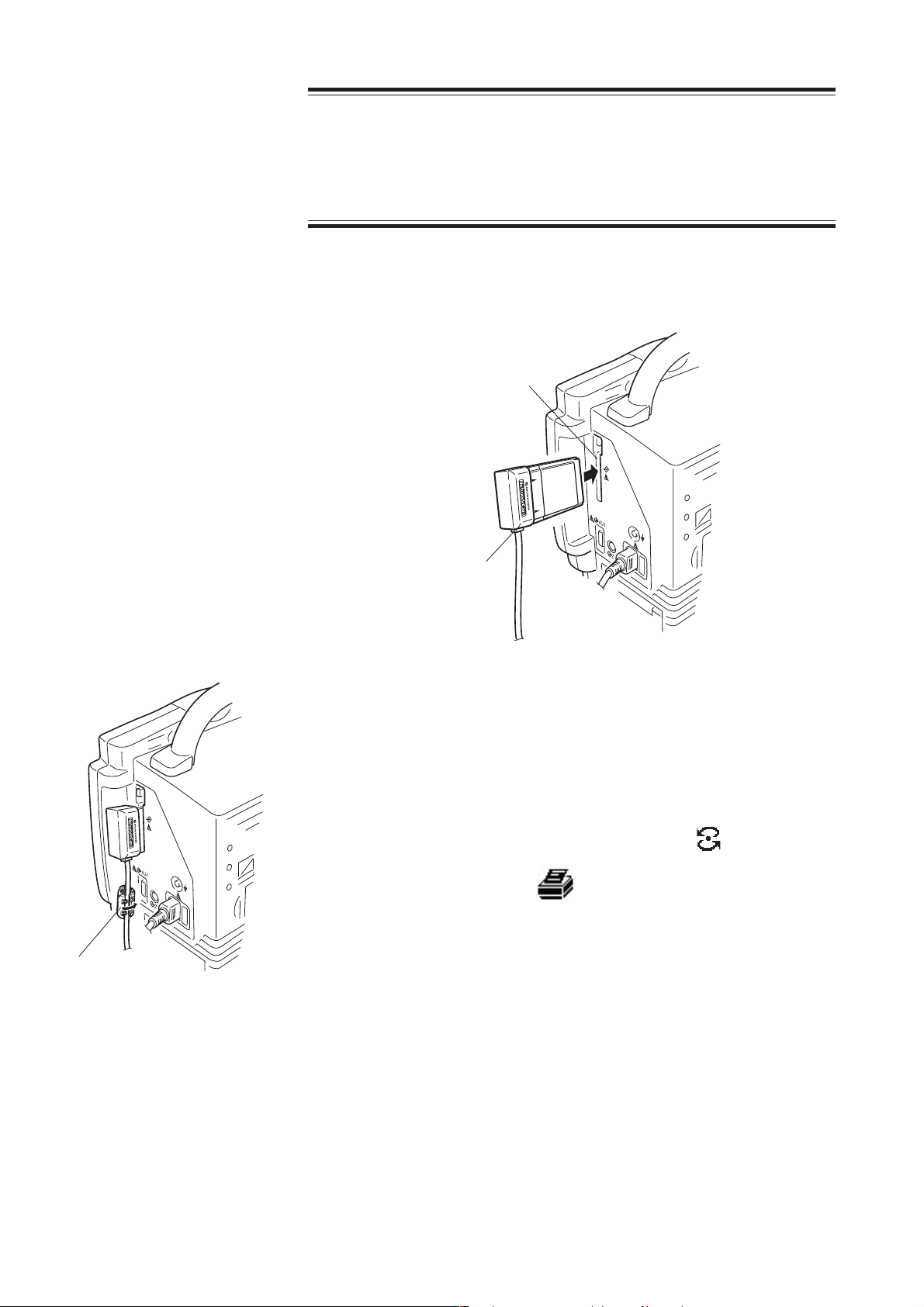
2. PREPARATIONS
CAUTION
Do not push in the network cable with too much force. Otherwise the
network card, network printer card or bedside monitor may get
damaged.
2. Insert the network card or network printer card into the PC card slot on the
right side panel with the cable side facing down.
PC card slot
Ferrite core
Network cable
socket
3. Attach the ferrite core to the network cable.
NOTE
A ferrite core must be attached to every network cable.
4. When the network card/network printer card is installed, the data is
communicated between the monitors in the network. The icon appears
when using network card or the icon appears when using network printer
card at the upper right corner of the screen during communication.
2.10 Operator's Manual BSM-2300A
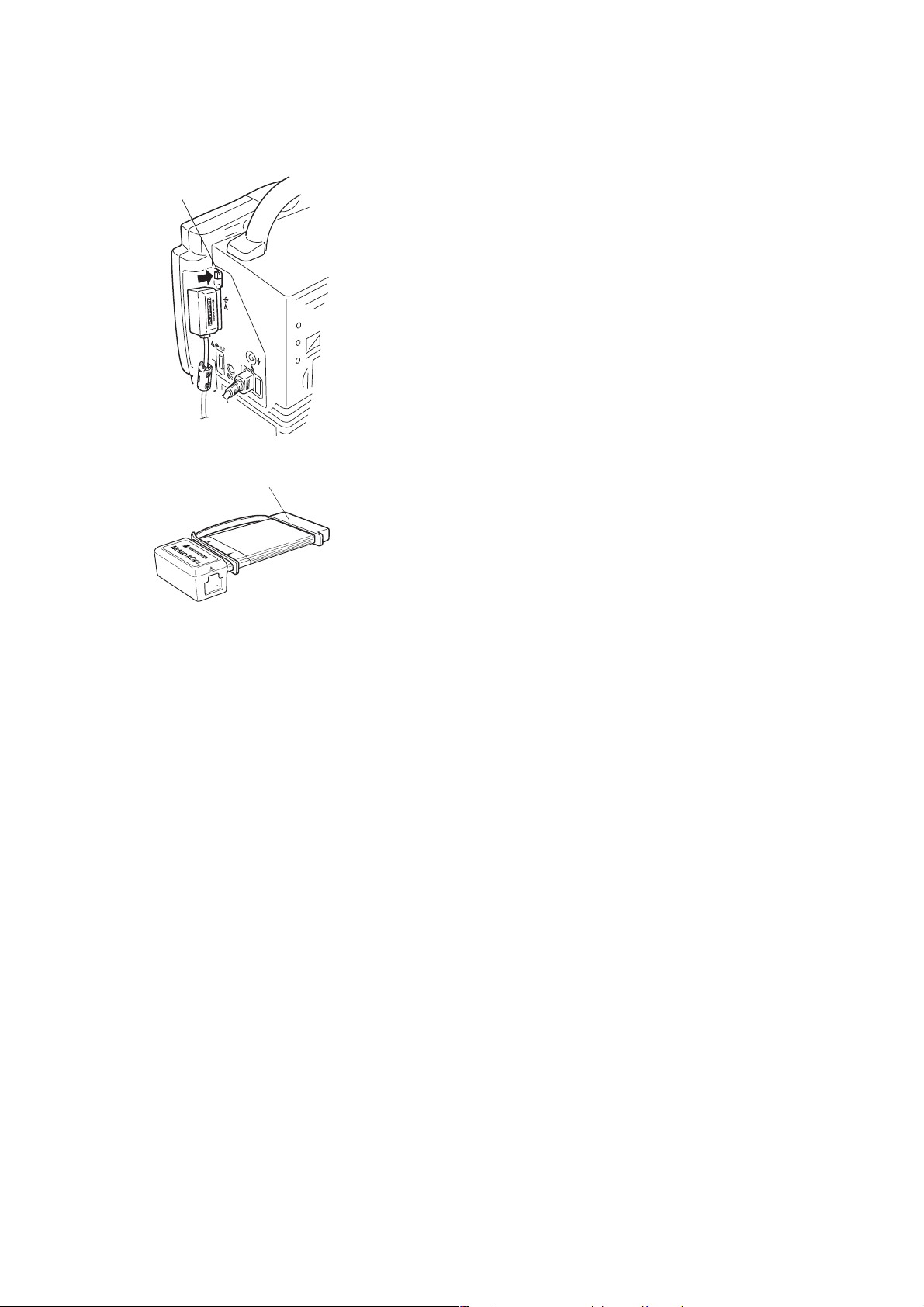
2. PREPARATIONS
Removing the Network
Card or Network Printer
Card
PC card eject button
Rubber cap
1. Press the PC card eject button and remove the network card/network printer
card from the monitor.
NOTE
The network card/network printer card may get hot after long term use,
but this does not mean that the card is damaged.
2. Remove the network cable from the network card/network printer card.
3. Check that there is no scratches, dirt or damage to the network card/network
printer card, attach the rubber cap to the PCMCIA connector as shown below
and store the card in an appropriate place.
Using the QI-210P Wireless
LAN station
With an optional QI-210P wireless LAN station and QI-902R wireless LAN access
point, the bedside monitor data can be radio communicated to the monitor network.
The wireless LAN station is mounted on the bedside monitor and the cable of the
wireless LAN station is connected to the QI-101P network card installed on the
bedside monitor. The wireless LAN access point is installed in your facility and
connected to the monitor network. The monitor data is communicated between the
wireless LAN station and wireless LAN access point and is sent from the wireless
LAN access point to the central monitor or any other monitor in the network. For
details, contact your Nihon Kohden distributor.
Operator's Manual BSM-2300A 2.11

2. PREPARATIONS
Power
AC or Battery Power
Source Selection
The monitor can operate on either battery or AC power.
When the power cord is plugged into an AC outlet and the power switch on the
front panel is turned on, the monitor operates on AC power.
When a battery is installed and the power cord is disconnected, such as when
transferring a patient, the monitor automatically switches to battery power.
The battery is charged when the power cord is plugged into an AC outlet and the
AC current is supplied to the monitor. The battery is also charged during
monitoring.
When the monitor is operated on battery power, the brightness of the screen can be
reduced to save battery power. Refer to Section 3.
The monitor can operate for about 3 hours with a fully charged battery pack when:
• Charged and used in normal temperature (about 25°C)
• Recorder is not used
• No alarm occurs
• No NIBP measurement
• POWER SAVING MODE on the SYSTEM SETUP screen is set to ON.
Connecting the Power
Cord and Grounding the
Monitor
Lights
Connecting the Power Cord
WARNING
••
• Only use the provided power cord. Using other power cords may
••
result in electrical shock or other injury to the patient and operator.
••
• When the provided power cord cannot be used, operate the monitor
••
on battery power.
Connect the provided power cord to the AC SOURCE socket on the side panel of
the monitor and plug the cord into a 3-prong AC outlet.
When the AC power is supplied to the monitor, the AC power lamp on the front
panel lights and a buzzer sounds.
NOTE
If the AC power lamp does not light or there is no buzzer sound, check
the power cord connection.
2.12 Operator's Manual BSM-2300A

2. PREPARATIONS
Grounding the Monitor
WARNING
••
• For patient safety, equipotential grounding of all instruments must
••
be performed. Consult with a qualified biomedical engineer.
••
• When equipotential grounding is doubtful (such as in poor
••
grounding facility), operate the monitor on battery power.
When more than one electrical instrument is used, there may be electrical potential
difference between the instruments. The potential difference between the
instruments may cause current to flow to the patient connected to the instruments,
resulting in electrical shock (micro shock).
Always perform equipotential grounding when required. It is often required in the
operating room, ICU room, CCU room, cardiac catheterization room and X-ray
room. Consult with a biomedical engineer to determine if it is required.
Turning the Monitor On
When equipotential grounding is required, connect the equipotential ground
terminal on the instrument to the equipotential ground terminal on the wall
(equipotential grounding system) with the equipotential grounding lead (potential
equalization conductor).
Check Before Turning On the Monitor
Check the following items before turning on the monitor.
• Enough electrodes and electrode leads are ready.
• Cleaned and sterilized sensors and transducers are ready.
• Power cord is connected properly.
• Equipotential grounding lead is connected properly when equipotential
grounding is required.
• All cables are connected properly.
• Batteries are fully charged when operating on battery power.
• No scratches, damage or dirt on the monitor.
• No damage to the keys, switch and panels.
• No damage to the power cord.
• No damage to the electrode leads, transducers, probes and cables.
• The monitor is not in a wet place.
• The handle and hooks (option) are not damaged.
• Enough recording paper in the recorder (when using an optional recorder
module).
Operator's Manual BSM-2300A 2.13

2. PREPARATIONS
Turning the Monitor On
CAUTION
Do not turn the monitor off when the system check screen is
displayed. Otherwise the saved data may be damaged or deleted. If
the monitor is turned off during system check, delete all data because
the data is not reliable.
NOTE
••
• It takes a few minutes for the LCD screen to reach full brightness.
••
••
• The shadow of the previous screen may remain for a few minutes
••
after changing screens.
••
• There may be some dots on the LCD screen which are always on or
••
always off, but it does not affect monitoring. This is normal for all
LCD screens.
Light
Light
CAUTION
At the monitor on, check that one “bong” sounds and the red alarm
lamp, yellow alarm lamp and green lamp blink once to show that the
alarm functions properly.
••
• When operating on battery power
••
After installing a fully charged battery pack, press the power switch on the front
panel to ON. The power and battery power lamps light, a buzzer sounds and the
“CHECK PROGRAM RUNNING” message appears on the screen.
If the power and battery power lamps do not light and there is no buzzer sound,
check the battery condition.
When the power is turned on again within one hour after using the monitor on
battery, the buzzer does not sound.
••
• When operating on AC power
••
After grounding and connecting the power cord, press the power switch on the
front panel to ON. The power lamp and the AC power lamp light and the
“CHECK PROGRAM RUNNING” message appears on the screen.
If the power lamp does not light, check the power cord connection.
2.14 Operator's Manual BSM-2300A

2. PREPARATIONS
Standby Mode
When the monitor power is turned on, it enters “standby mode” while the monitor
is waiting for the electrodes and probe to be attached to the patient. “CHECK
ELECTRODES”, “CHECK PROBE”, “CANNOT DETECT PULSE” and “CHECK
SENSOR” alarms will not be activated. “DETECTING PULSE” message will not
be displayed. The monitor changes from standby mode to normal monitoring when
the ECG or SpO
monitoring starts. The monitoring starts when the connection
2
cord is connected to the socket on the monitor and electrodes or probe is attached
to the patient.
If the monitor power is turned off and on again within 10 seconds, the monitor
skips standby mode.
Check After Turning On the Monitor and During Monitoring
To start monitoring safely and properly, check the following items after turning on
the monitor. If any problem is detected, take the proper countermeasure according
to the troubleshooting and maintenance sections.
• There is no fire, smoke or smell.
• The monitor is not too hot.
• The power lamp lights.
• Alarm indicators blink once and a bong sounds.
• The start up screen appears and the monitoring screen appears.
• No error message is displayed on the screen.
• The time on the screen is correct.
• The low battery mark does not appear on the screen when operating on battery.
• The monitor does not affect surrounding equipment.
• The data and waveforms are displayed properly.
• Keys and switch operate properly.
• The touch keys function properly.
• Alarm functions properly.
• There is no trouble in recording (when using an optional recorder module).
• Calibration is performed properly. Refer to “Calibrating Waveforms”in Section
18.
NOTE
After turning the monitor on and when admitting a patient on the
monitor, make sure that the time displayed at the upper right of the
screen is correct. When the date or time is changed during monitoring,
the date and time of all stored data is also changed and may not match
the date and time on the printout.
When the monitor is connected to a network
The time on this monitor is automatically adjusted to match the time of
the network as long as the monitor is connected to the network. The
date and time on all monitors in the network are set to the same
setting.
Operator's Manual BSM-2300A 2.15

2. PREPARATIONS
Turning the Monitor Off
Off
1. Press the power switch on the front panel for more than one second to turn the
monitor off. The screen becomes dark and the power lamp on the front panel
turns off.
Check After/Before Turning the Monitor Off
Check the following items for the next use.
• Previous patient data is deleted.
• Temporarily changed settings are changed back to the previous settings.
• There is no dirt, damage or scratches on the monitor.
• The sensors, probes, transducers, and cables are cleaned and sterilized.
• Accessories are cleaned and stored properly.
• There are enough consumables, such as recording paper, and disposable
electrodes for the next use.
• Battery pack is fully charged.
• Battery pack is removed from the monitor when not operating for a long period
of time.
• The power switch on the monitor is turned off and the power cord is
disconnected from the monitor.
• The monitor is not in a wet place.
• Dead batteries are disposed of properly.
• The medical waste is disposed of properly.
• The monitor is stored properly.
Power and Battery Status
Indications
Power and battery status are indicated by four lamps on the front panel. A
discharged battery is also indicated by a screen message and alarm.
NOTE
When charging the battery with the monitor power switch turned off,
check that the power lamp and battery charging lamp light. If the
lamps do not light even when the power cord is connected and the
battery is inserted, turn the power switch on, check that the battery
charging lamp is blinking or lit, then turn the power switch off.
• Operating on AC power and battery is fully charged
Power lamp: Lit
AC power lamp: Lit
Battery power lamp: Off
Lit
Lit
Lit
Slow blinking or lit
Battery charging lamp: Lit
• Operating on AC power and battery is being charged
Power lamp: Lit
AC power lamp: Lit
Battery power lamp: Off
Battery charging lamp: Slow blinking (once every 2 seconds) or lit
Lit
Lit
2.16 Operator's Manual BSM-2300A

Lit
Lit
Lit
Lit
Rapid blinking
Lit
Lit
2. PREPARATIONS
• Operating on AC power with no battery
Power lamp: Lit
AC power lamp: Lit
Battery power lamp: Off
Battery charging lamp: Off
• Operating on AC power and battery is damaged
Power lamp: Lit
AC power lamp: Lit
Battery power lamp: Rapid blinking (4 times per second)
Battery charging lamp: Rapid blinking (4 times per second)
• Operating on battery power
Power lamp: Lit
AC power lamp: Off
Battery power lamp: Lit
Battery charging lamp: Off
Lit
Rapid blinking
Lit
Slow blinking or lit
Battery Handling and
Operation
• Operating on battery power and battery needs recharging
Power lamp: Lit
AC power lamp: Off
Battery power lamp: Rapid blinking (4 times per second)
Battery charging lamp: Off
Screen indication: “BATTERY WEAK” message
Alarm indication: Continuous “bing bong” sound and blinking
yellow alarm lamp
• No monitoring and charging battery
Power lamp: Off
AC power lamp: Lit
Battery power lamp: Off
Battery charging lamp: Slow blinking (once every 2 seconds) or lit
Safety Information
WARNING
••
• Keep the battery pack away from fire. The battery pack may explode.
••
••
• Do not heat the battery pack. The battery pack may explode.
••
••
• Never short-circuit the + and – terminals on the battery pack with a
••
wire or store the battery pack with metals such as necklace or hair
pins. The battery pack may short-circuit, causing the substance
inside the battery to leak or explode.
••
• Never disassemble or modify the battery pack. Never damage or
••
directly solder the sheath tube. The battery pack short-circuits, the
electrolyte comes out and the battery pack explodes.
••
• Do not subject the battery pack to a strong mechanical shock. The
••
battery may leak or explode.
Operator's Manual BSM-2300A 2.17

2. PREPARATIONS
••
• Do not use a battery which is damaged, such as from falling. There
••
is a gas discharge valve inside the battery and if this valve is
damaged, the gas cannot be discharged, causing the battery to
explode.
••
• Only use the battery pack on the specified instrument. If the battery
••
is used on an unspecified instrument, large current may flow,
causing the battery to explode.
••
• If the battery pack is damaged and the substance inside the battery
••
(alkaline liquid) contacts the eyes or skin, wash immediately and
thoroughly with water and see your physician. Never rub your eyes,
otherwise you may lose your eyesight.
••
• The battery pack has + and – polarity. Make sure that the battery is
••
installed with the correct polarity direction. Otherwise, the
substance inside the battery may leak and explode.
••
• Do not connect the battery pack to an AC outlet or lighter socket in a
••
car. The battery may explode.
••
• Do not immerse the battery pack in water or seawater. The battery
••
will rust and may heat up.
••
• Never use a battery pack which is damaged, discolored or has
••
leakage. A damaged battery may explode if used.
CAUTION
••
• Do not expose the battery pack to direct sunlight or leave in a high
••
temperature place. The lifetime of the battery pack may be shortened
or the substance inside the battery pack may leak.
••
• Do not leave a used battery pack for a long period of time (more than
••
one year). The substance inside the battery may leak.
••
• The battery pack must be replaced by qualified service personnel.
••
••
• Keep the battery pack away from children.
••
••
• Before disposing of the battery, check with your local solid waste
••
officials for details in your area for recycling options or proper
disposal. The battery is recycleable. At the end of its useful life,
under various state and local laws, it may be illegal to dispose of this
battery into the municipal waste stream.
NOTE
••
• Fully charge the new battery pack before using on the monitor.
••
••
• Do not use a battery pack which is past the expiration date written on
••
the label.
••
• Always charge the battery between 10°C (50°F) and 40°C (104°F).
••
Temperatures out of this range affect the working of the battery and
may cause the battery pack to leak or explode.
••
• Do not leave a battery pack inside the monitor without the power
••
cord connected between the monitor and AC outlet. The battery pack
may be over-discharged and can no longer be used.
2.18 Operator's Manual BSM-2300A

2. PREPARATIONS
••
• When not using the monitor for a long period of time (more than two
••
months), remove the battery pack from the monitor and store the
battery at temperatures between –20°C (–4°F) and +30°C (86°F) and
low humidity.
••
• Before disposing of the monitor, make sure that the battery pack is
••
removed from the monitor.
Battery Lifetime
The battery pack lifetime is one year or 200 cycles of discharging/charging. Write
the date of first use of the battery on the start date label provided with the battery
pack and attach it to the bedside monitor where it is easy to see (upper part of the
left side panel recommended). Write the same date on the label of the battery pack.
When the battery operating time becomes less than two hours, replace the battery
with a new one.
Use a battery until it is fully discharged (BATTERY WEAK message appears), then
fully charge the battery. The battery life will be longer if it is fully discharged
before charging it again.
Battery Handling Procedures
• Every time the monitor is used on battery power, charge the battery immediately
after use.
• Replace the battery with a new one after 200 cycles of discharging/charging or
after one year, whichever comes first. This is because the battery is a chemical
product which gradually deteriorates whether or not it is used.
When Using a Battery for the First Time or After Storage
• Fully recharge the battery before using it for the first time or after storing it for
over a month. When the battery is not used, it self-discharges.
When Not Using the Monitor or Battery
WARNING
Do not leave the battery for more than two years unused. The battery
may leak.
• When not using the monitor for one to two months, fully charge the battery
before storing the monitor.
• When not using the monitor for more than two months, remove the battery.
When a charged or discharged battery is left inside the monitor with the power
cord unplugged, the battery self-discharges and deteriorates.
• Store the battery packs under the following conditions.
Temperature: –20 to 30°C (–4 to 86°F)
Humidity: 65% ±20% relative humidity
Operator's Manual BSM-2300A 2.19

2. PREPARATIONS
When the BATTERY WEAK Message Appears
When the “BATTERY WEAK” message appears, connect the power cord to the
monitor, operate the monitor on AC power and charge the battery.
If no AC or battery power is supplied to the monitor, there is no measurement or
display but no data is lost.
When using a fully charged battery, the battery has approximately 5 to 15 minutes
of power left when the “BATTERY WEAK” message is displayed.
Installing or Replacing the Battery
The battery pack must be installed or replaced by qualified service personnel.
Refer to the bedside monitor service manual.
Charging the Battery
The battery pack can only be charged by the monitor. It takes about 16 hours to
charge a battery pack on the monitor.
The monitor can operate for about 3 hours with a fully charged battery pack when:
• Charged and used in normal temperature (about 25°C)
• Recorder is not used
• No alarm occurs
• No NIBP measurement
• POWER SAVING MODE on the SYSTEM SETUP screen is set to ON.
CAUTION
When charging the battery pack, keep the ambient temperature at
approximately 20°C to maintain the optimal battery operation time. If
the battery pack is charged at less than 10°C (50°F) or more than 40°C
(104°F), the maximum battery operation time will be 20% to 30% less
than the optimal operation time.
During AC operation, the battery is automatically charged without interrupting
monitoring. It takes approximately 16 hours of continuous charging to fully charge
the battery pack. After 16 hours of continuous charging, the monitor automatically
switches to trickle charging mode to maintain the battery pack fully charged.
Trickle charging is necessary because the battery pack can self-discharge even
when it is not in use.
NOTE
••
• Do not disconnect the power cord from the monitor during battery
••
charging.
••
• If the 16 hours of continuous normal charging is disrupted for more
••
than one hour by power failure in the main power supply or by
2.20 Operator's Manual BSM-2300A

Lit
2. PREPARATIONS
temporary removal of the battery pack from the monitor, the
monitor’s normal charging circuit is reset, and the battery pack is
charged for another 16 hours regardless of how many hours it was
charged before the disruption. This deteriorates the battery.
1. Install the battery pack into the monitor.
2. Connect the power cord to the monitor and the AC outlet. The monitor charges
the battery pack regardless of whether the monitor power switch is on or off.
During charging, the battery charging lamp on the front panel blinks.
After 16 hours, the battery charging lamp is continuously lit and the battery
charging is completed.
Slow blinking or lit
Disposal of Battery Pack
Before disposing of the battery, check with your local solid waste officials for
details in your area for recycling options or proper disposal. The battery is
recycleable. At the end of its useful life, under various state and local laws, it may
be illegal to dispose of this battery into the municipal waste stream.
Operator's Manual BSM-2300A 2.21

Section 3 Changing System Setup
Settings
Displaying the SYSTEM SETUP Screen ............................................................................ 3.2
Changing Settings .....................................................................................................3.3
Closing the SYSTEM SETUP Screen and Displaying the Monitoring Screen ........... 3.3
List and Explanation of the SYSTEM SETUP Settings ....................................................... 3.4
List of All Settings .....................................................................................................3.4
Site Setting (SITE) ....................................................................................................3.6
Display Settings (DISPLAY SETUP) ......................................................................... 3.7
Bed ID Setting (BED ID SETUP) ..............................................................................3.8
Parameter and Other Settings (PARAMETER SETUP) ............................................. 3.9
Alarm Settings (ALARM SETUP) ............................................................................3.10
Unit Settings (UNITS SETUP) ................................................................................ 3.14
Color Settings (COLOR SETUP) ............................................................................. 3.15
Recording Settings (RECORD SETUP) ...................................................................3.18
Other Settings (OTHER SETUP) ............................................................................. 3.19
Alarm Master Settings (ALARM MASTER) ............................................................. 3.20
Arrhythmia Recall Master Settings (ARRHYTHMIA RECALL MASTER) ................ 3.22
Network Settings (NETWORK SETUP) ...................................................................3.23
Network Printer Settings (PRINTER SETUP) .......................................................... 3.24
External Interface Information (EXT I/F SETUP) .................................................... 3.26
Initializing the System .......................................................................................................3.27
Operator's Manual BSM-2300A 3C.1

3. CHANGING SYSTEM SETUP SETTINGS
This section explains how to change settings after the monitor is installed and
before monitoring waveforms.
The initial settings on the SYSTEM SETUP screen must be changed before
monitoring. Changing these settings during monitoring interrupts monitoring.
All other settings can be changed any time without interrupting monitoring.
This section also explains how to initialize the system. This procedure returns all
settings to the factory default settings and deletes all stored data in memory.
Operator's Manual BSM-2300A 3.1
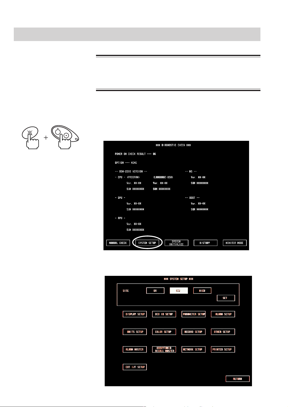
3. CHANGING SYSTEM SETUP SETTINGS
Displaying the SYSTEM SETUP Screen
This procedure interrupts all monitoring. Only change these settings
before or after monitoring.
1. Turn the monitor power off.
WARNING
SILENCE
ALARMS
2. Press the power switch while pressing the SILENCE ALARMS key on the front
panel until the DIAGNOSTIC CHECK screen is displayed.
3. Touch the “SYSTEM SETUP” key. The SYSTEM SETUP screen appears.
3.2 Operator's Manual BSM-2300A

3. CHANGING SYSTEM SETUP SETTINGS
Changing Settings 1. Touch the desired item on the SYSTEM SETUP screen. A setup screen for that
item appears.
2. Touch a setting key on the screen to set the condition.
3. Touch the “RETURN” key to return to the SYSTEM SETUP screen.
4. Repeat steps 1 to 3 to change other setup settings.
Closing the SYSTEM
SETUP Screen and
Displaying the Monitoring
Screen
1. After you change all desired settings, touch the “RETURN” key on the
SYSTEM SETUP screen. The new settings are entered and the screen returns
to the DIAGNOSTIC CHECK screen.
2. Touch the “MONITOR MODE” key. After a few seconds, the monitoring
screen appears.
Operator's Manual BSM-2300A 3.3

3. CHANGING SYSTEM SETUP SETTINGS
List and Explanation of the SYSTEM SETUP Settings
List of All Settings The factory default settings are underlined.
SETUP type Item Setting Conditions
SITE OR, ICU, NICU
DISPLAY SETUP
BEDIDSETUP
PARAMETER
SETUP
ALARM SETUP
UNITS SETUP
* This setting is not available on the BSM-2304 monitor.
WAVE DISPLAY FIXED, MOVING
SWEEP SPEED 25 mm/s, 50 mm/s
DISPLAY COLOR MODE PARAMETER, ALARM
POWER SAVING MODE ON, OFF
Up to 8 alphanumeric characters
OR: OR-001, ICU: ICU-001
LINE FREQUENCY* AUTO, 50Hz, 60 Hz
NIBP MODE AFTER STAT MANUAL, 2 min, 2.5 min, 5 min, 10 min, 15 min, 30 min
OLD NIBP DATA
AFTER
NIBP COMPLETION SOUND ON, OFF OR: ON ICU, NICU: OFF
N IBP S TAT M ODE S TAT , 1 m i n
NIBP INTERVAL MASTER
ECG ELECTRODE IEC, AHA
NOISE REDUCTION ON
IMPEDANCE RESP
PRESS FILTER 10 Hz, 20 Hz
SILENCE TIME 1 min, 2 min
ALARM LIMIT DISPLAY
EXIT SLEEP MODE ON ALARM YES, NO
ALARMS OFF TYPE
SUSPEND ALARM TIME 0 min, 1 min, 3 min
SUSPEND MONITORING ON
DATA DELETION
ALARM
LEVEL
PRESSURE UNIT mmHg, kPa
TEMPERATURE UNIT CENTIGRADE, FAHRENHEIT
ST UNIT mV, mm
HEIGHT UNIT cm, inch
HR CRISIS, WARNING, ADVISORY
SpO2 CRISIS, WARNING, ADVISORY
PRESS CRISIS, WARNING, ADVISORY
NIBP CRISIS, WARNING, ADVISORY
APNEA
ECG CHECK
ELECTRODES
SpO2 CHECK
PROBE
ECG NOISE WARNING, ADVISORY
VPC RUN CRISIS, WARNING, ADVISORY
COUPLET CRISIS, WARNING, ADVISORY
EARLY VPC CRISIS, WARNING, ADVISORY
BIGEMINY CRISIS, WARNING, ADVISORY
FREQ VPC CRISIS, WARNING, ADVISORY
TACHYCARDIA CRISIS, WARNING, ADVISORY
BRADYCARDIA
DIM, HIDE
10 min, 30 min, 1h, 24h OR: 10 min ICU, NICU: 30 min
MANUAL, STAT, 2 min, 2.5 min, 5 min, 10 min, 15 min, 30
min, 1 h, 2 h, 4 h, 8 h
ON, OFF
MARK BRIGHT, MARK DIM, VALUES
OR, ICU: MARK BRIGHT NICU: VALUES
SUSPEND MONITORING, BYPASS, ALL ALARMS OFF
OR: BYPASS ICU, NICU: SUSPEND MONITORING
YES, NO
CRISIS, WARNING, ADVISORY
OR, ICU: WARNING NICU: CRISIS
WARNING, ADVISORY
WARNING, ADVISORY
CRISIS, WARNING, ADVISORY
OR, ICU: WARNING NICU: CRISIS
, NICU: NICU-01
3.4 Operator's Manual BSM-2300A

3. CHANGING SYSTEM SETUP SETTINGS
SETUP type Item Setting Conditions
COLOR SETUP
RECORD SETUP
(For the optional
recorder module)
OTHER SETUP
ARRHYTHMIA RECALL MASTER See explanation in following pages.
NETWORK
SETUP**
PRINTER SETUP
EXT I/F SETUP
PARAMETER COLOR Green, scarlet, pink, sky blue, violet, pale yellow, pale
green, light blue, white (black), orange, yellow, red
Default settings
ECG: green RESP/CO2: white NIBP: pink
SpO2: sky blue ART, ART-2, RAD, DORS, AO,
FEM, UA, LVP, PRESS: red UV, CVP, RAP,
PRESS-2: light blue PAP, RVP, LAP: yellow ICP,
ICP-2: pale yellow TEMP: orange
PARAMETER (EXTERNAL) Green, scarlet, pink, sky blue, violet, pale yellow, pale
green, light blue, white (black), orange, yellow, red
Default settings
Fi/EtCO2: white Fi/EtN2O: light blue
Fi/EtO2:green Fi/EtHAL: red Fi/EtISO: violet
Fi/EtENF: orange Fi/EtDES: sky blue Fi/EtSEV:
yellow CNIBP: orange
ALARM MODE COLOR Green, scarlet, pink, sky blue, violet, pale yellow, pale
green, light blue, white (black)
BACKGROUND BLACK, WHITE
MANUAL RECORD REAL TIME, DELAY
MANUAL RECORD TIME CONTINUOUS, 10 sec, 20 sec, 30 sec
PERIODIC FREE INTERVAL 1 to 120 min (1 min steps), 15 min
SYNC SOUND PITCH LOW, MIDDLE, HIGH
ALARM INDICATOR QRS SYNC ON, OFF OR, NICU: OFF ICU: ON
ZB-900P TYPE 8, A
TIME ZONE 0 to±12:00in30minsteps,+9:00
EXTERNAL OUTPUT
VITAL See explanation in following pages.ALARM MASTER
ARRHYTHMIA See explanation in following pages.
GAS See explanation in following pages.
GROUP
DEFAULT GATEWAY 255.255.255.255, 000.000.000.000
IP ADDRESS SETUP AUTO, MANUAL
MANUAL IPADDRESS 255.255.255.255, 010.000.000.001
MANUAL SUBNET MASK 255.255.255.255, 255.000.000.000
PRINTER
SETUP
PRINTER NAME Up to 8 alphanumerics, lp
HOSPITALNAME Upto32alphanumerics
PAPER SIZE A4, LETTER
PRINTER TYPE MONOCHROME, COLOR
IP ADDRESS 255.255.255.255, 000.000.000.000
ECG ANALOG OUT, QRS SYNC SIGNAL,
ALARM CRISIS, ALARM CRISIS & WARNING
General, CCU, CCU-1, CCU-2, ER, ICU, ICU-1,
ICU-2, OR, Post CCU, Recovery, Tele-1, Tele-2, Tele-
3, Tele-4, Tele-5
RS-232C information of the interface connected to the
monitor. Refer to the interface manual.
** These items can only be set when the optional QI-101P network card or QI-111P network printer card is installed
in the monitor.
Operator's Manual BSM-2300A 3.5
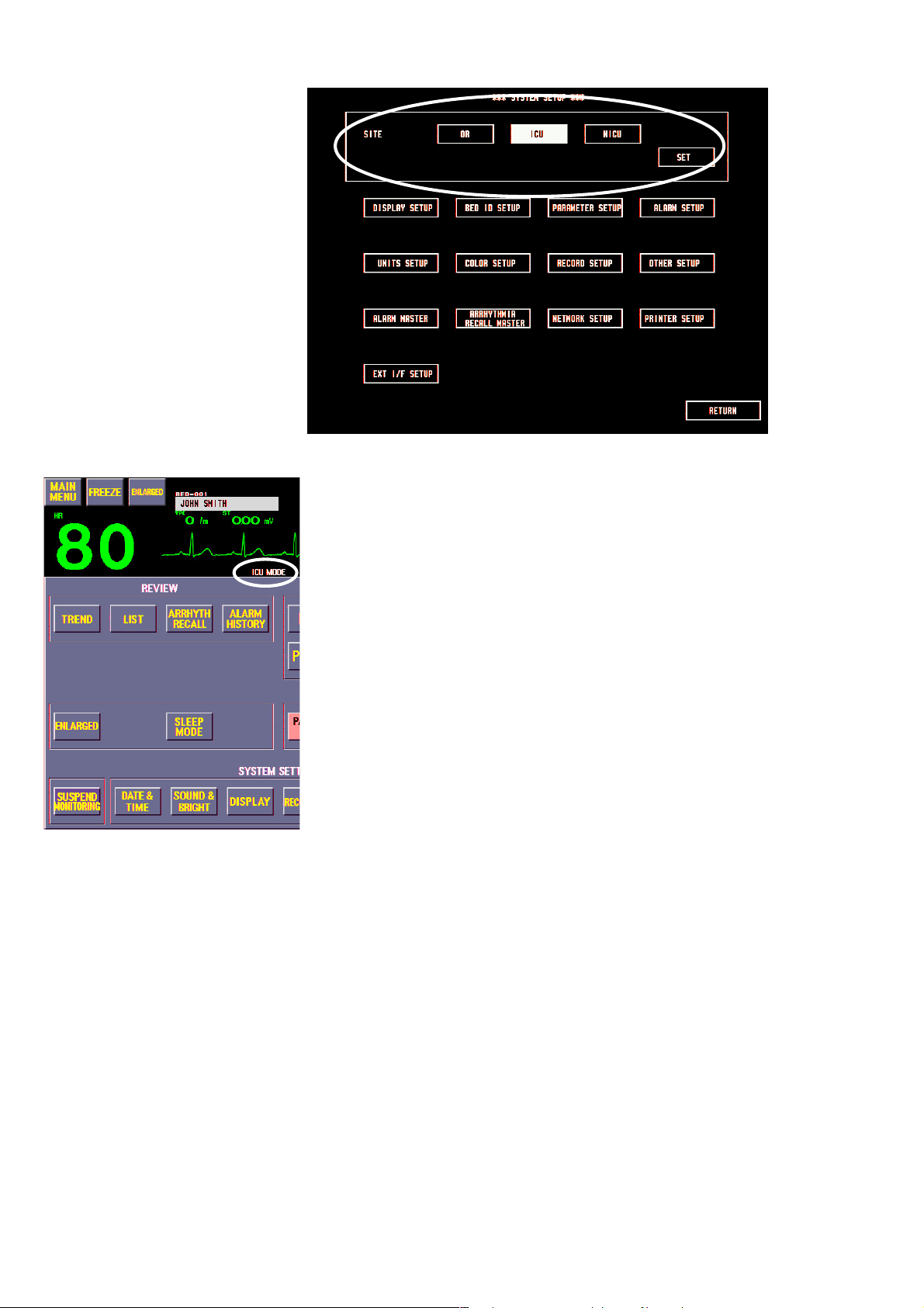
3. CHANGING SYSTEM SETUP SETTINGS
Site Setting (SITE)
SITE: OR, ICU, NICU
Select the site according to the environment. The default settings, including alarm
upper and lower limit settings, differ according to site.
OR: The “BYPASS” key is displayed on the MENU window. Sleep mode
ICU, NICU: The “SUSPEND MONITORING” key is displayed on the MENU
is not available.
window. Sleep mode is available.
When “ALL ALARMS OFF” is selected for ALARMS OFF TYPE on the ALARM
SETUP screen, the “ALL ALARMS OFF” key is displayed instead of the
“BYPASS” or “SUSPEND MONITORING” key on the MENU window. Refer to the
“Alarms Settings” section.
For details on the functions of the “BYPASS”, “SUSPEND MONITORING” and
“ALL ALARMS OFF” keys, refer to “Silencing and Suspending Alarms” in Section
6.
To change the site, select the new site and touch the “SET” key. When the site is
changed, some settings whose factory default settings differ according to site
return to the factory default settings for the new site. Other settings do not change.
3.6 Operator's Manual BSM-2300A
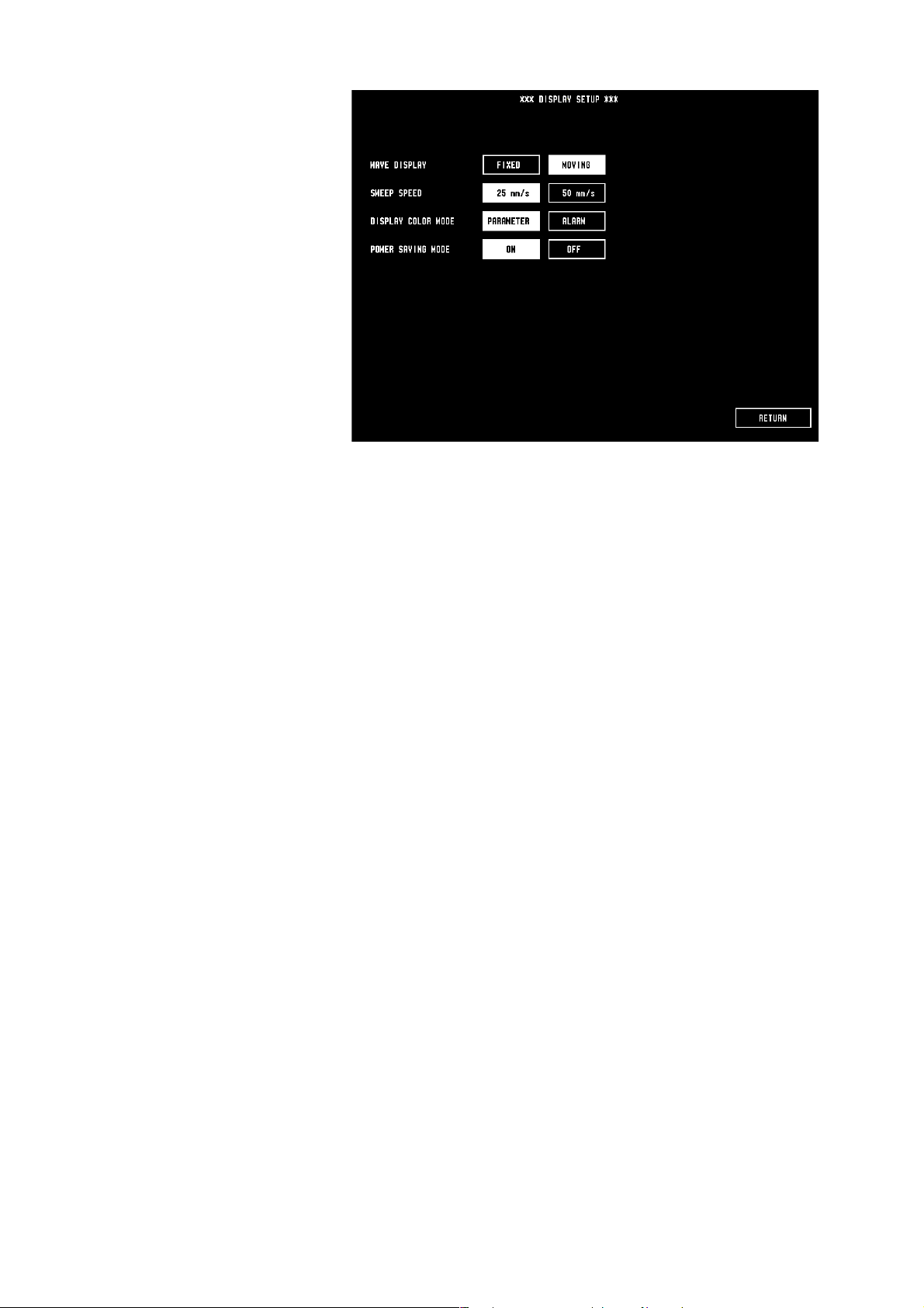
Display Settings
(DISPLAY SETUP)
3. CHANGING SYSTEM SETUP SETTINGS
WAVE DISPLAY: FIXED, MOVING
Set waveform sweep mode and trendgraph display on the monitoring screen on or
off.
FIXED: Waveform is fixed and renewed from the left. Trendgraph or OCRG
cannot be displayed on the monitoring screen.
MOVING: Waveform sweeps from the right. Trendgraph or OCRG can be displayed
on the monitoring screen.
SWEEP SPEED: 25 mm/s, 50 mm/s
Select waveform sweep speed.
DISPLAY COLOR MODE: PARAMETER, ALARM
There are two color display modes.
PARAMETER: A different color can be set for each parameter. When an alarm
occurs, the alarmed parameter data is highlighted.
ALARM: The same color selected at ALARM MODE COLOR of the
COLOR SETUP is set for all parameters. When an alarm occurs,
the alarmed parameter color changes to red or yellow according to
the alarm level set at ALARM LEVEL of the ALARM SETUP.
CRISIS: red
WARNING: yellow
ADVISORY: yellow
POWER SAVING MODE: ON, OFF
When operating the monitor on battery power, the brightness of the screen can be
adjusted to save battery power.
ON: Dim, longer battery operation time
OFF: Normal screen brightness, shorter battery operation time
Operator's Manual BSM-2300A 3.7
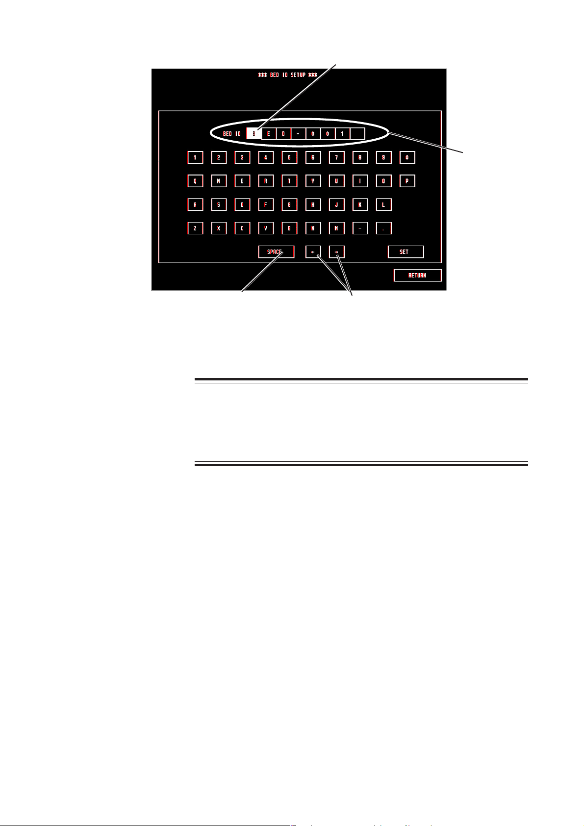
3. CHANGING SYSTEM SETUP SETTINGS
Bed ID Setting
(BED ID SETUP)
Cursor
Entered data
Enters space
Enter an identification name for the bed. Up to 8 alphanumeric characters can be
entered.
Moves the cursor
CAUTION
When the monitor is connected to a central monitor network, set the
Bed ID on the monitor to correctly identify the bed on the central
monitor.
1. Touch the desired letters and numbers to enter the bed ID.
2. Touch the “SET” key to register the bed ID.
3. Touch the “RETURN” key to return to the SYSTEM SETUP screen.
3.8 Operator's Manual BSM-2300A

Parameter and Other
Settings
(PARAMETER SETUP)
3. CHANGING SYSTEM SETUP SETTINGS
LINE FREQUENCY: AUTO, 50 Hz, 60 Hz
Select line frequency. In normal use, set to AUTO. This setting is not available on
the BSM-2304 monitor.
NOTE
When operating on battery, make sure that the appropriate line
frequency is selected. Otherwise, noise may interfere on the pulse
waveform.
AUTO: Automatically detects the AC line frequency
50 Hz: Set to 50 when operating on battery only in a 50 Hz area
60 Hz: Set to 60 when operating on battery only in a 60 Hz area
NIBP MODE AFTER STAT: MANUAL, 2, 2.5, 5, 10, 15, 30 min
The NIBP measurement mode after completing STAT (continuous) measurement
changes to the Manual mode or Auto mode with the selected interval.
OLD NIBP DATA: DIM, HIDE
AFTER: 10 min, 30 min, 1 h, 24 h
Select whether to dim or hide the NIBP data after NIBP measurement and how long
to wait after NIBP measurement to dim or hide it.
NIBP COMPLETION SOUND: ON, OFF
ON: When NIBP measurement is completed, one “bong” sounds.
OFF: No sound. However, when the STAT mode is selected for the NIBP
measurement, one “bong” sounds after completing STAT measurement.
NIBP STAT MODE: STAT, 1 min
There are two modes for STAT NIBP measurement.
STAT: Measure NIBP as many times as possible over a 15 minute period.
1 min: Measure NIBP every minute for a 15 minute period.
Operator's Manual BSM-2300A 3.9

3. CHANGING SYSTEM SETUP SETTINGS
NIBP INTERVAL MASTER: MANUAL, STAT, 2, 2.5, 5, 10, 15, 30 min, 1, 2, 4
or 8 h
Select the NIBP measurement mode to be set when the monitor is turned off for
more than 30 minutes, the monitor is initialized or the data is deleted on the
DELETE ALL window.
ECG ELECTRODE: IEC, AHA
Select the electrode lead type.
IEC: R, L, F, RF, C
AHA: RA, LA, LL, RL, V
NOISE REDUCTION ON IMPEDANCE RESP: ON, OFF
In the impedance method, noise from the heart beat may interfere on the respiration
waveform due to electrode position, and the respiration rate may increase to almost
the same rate as the heart rate. In such a case, set this setting to ON to reduce noise
interference on the respiration waveform.
If the respiration rate is miscounted in the thermistor method, set this item to OFF.
Alarm Settings
(ALARM SETUP)
NOTE
When this item is set to ON and the timing of the respiration and heart
beat coincide, respiration rate may not be counted. In such a case, set
this item to OFF or check the patient’s respiration by observing the
patient’s chest movement or the respiration waveform on the monitoring
screen.
PRESS FILTER: 10 Hz, 20 Hz
Select the noise filter for IBP monitoring. For normal monitoring, set the filter to
10 Hz. To see the IBP waveforms in detail, set the filter to 20 Hz.
SILENCE TIME: 1 min, 2 min
The interval for suspending an alarm can be selected.
3.10 Operator's Manual BSM-2300A

3. CHANGING SYSTEM SETUP SETTINGS
ALARM LIMIT DISPLAY: MARK BRIGHT, MARK DIM, VALUES
MARK BRIGHT: The
MARK DIM: The Vital Signs Alarm Off mark is displayed dimmed beside
VALUES: The upper/lower alarm limits are displayed beside parameter
EXIT SLEEP MODE ON ALARM: YES, NO
Vital Signs Alarm Off mark in normal brightness is
displayed beside the parameter values whose vital signs alarm is
set to OFF.
the parameter values whose vital signs alarm is set to OFF.
values. When the limit is set to OFF, “OFF” is displayed.
WARNING
When EXIT SLEEP MODE ON ALARM is set NO, the bedside monitor
alarm cannot be seen or heard on the bedside monitor during sleep
mode, Monitor the bedside monitor alarm on the central monitor or
telemetry system. Otherwise, the bedside monitor alarm may be
overlooked.
YES: When an alarm occurs during sleep mode, the sleep mode is exited and the
monitoring screen appears.
NO: The sleep mode continues even when an alarm occurs.
ALARMS OFF TYPE: BYPASS/SUSPEND MONITORING, ALL ALARMS
OFF
WARNING
Before setting ALARMS OFF TYPE, consult the administrator of this
monitor in your facility. Before selecting “ALL ALARMS OFF” or
“BYPASS”, all operators must thoroughly understand the function of
the “ALL ALARMS OFF” key and “BYPASS” key which turn all alarms
off for an indefinite period.
Select the type of all alarms off. The key for the selected type appears on the
MENU window. The “SUSPEND MONITORING” key is available in ICU or NICU
mode. The “BYPASS” key is available in OR mode.
SUSPEND MONITORING: When you temporarily stop patient monitoring for
examinations, you can use this key. When this key
is pressed, all alarms and NIBP STAT and Auto
measurements are suspended. Alarms resume when
the “SUSPEND MONITORING” key is pressed
again or when heart rate, SpO2, IBP or EtCO2 is
monitored for the SUSPEND ALARM TIME or
when NIBP is measured.
BYPASS: When the patient is connected to a heart-lung
machine, you can use this key. When this key is
pressed, all alarms and NIBP STAT and Auto
measurements are indefinitely suspended. Alarms
resume when the “BYPASS” key is pressed again.
Operator's Manual BSM-2300A 3.11

3. CHANGING SYSTEM SETUP SETTINGS
ALL ALARMS OFF: When this key is pressed, all alarms are indefinitely
SUSPEND ALARM TIME
Select when to release monitoring suspension and resume alarms when the
“SUSPEND MONITORING” key on the MENU window is pressed in ICU/NICU
mode or “YES” key on the DELETE ALL window is pressed when SUSPEND
MONITORING ON DATA DELETION is set to YES.
0 min: Alarms resume immediately when heart rate, SpO
1 min: Alarms resume when heart rate, SpO2, IBP or EtCO2 is monitored
3 min: Alarms resume when heart rate, SpO2, IBP or EtCO2 is monitored
SUSPEND MONITORING ON DATA DELETION
Select whether to enter standby mode when the “YES” key is pressed on the
DELETE ALL window. During standby mode, all alarms are suspended. Alarms
resume when heart rate, SpO2, IBP or EtCO2 is monitored properly for the interval
set for SUSPEND ALARM TIME or when NIBP is measured.
YES: Deletes data and enters standby mode
NO: Deletes data and does not enter standby mode
suspended. Alarms resume when the “ALL
ALARMS OFF” key is pressed again.
monitored or when NIBP is measured.
properly for 1 minute or when NIBP is measured.
properly for 3 minutes or when NIBP is measured.
, IBP or EtCO2 is
2
HR ALARM LEVEL: CRISIS, WARNING, ADVISORY
Heart rate alarm level and alarm indicator color can be selected. See “Alarm
Indications” in Section 6.
CRISIS: The heart rate data is highlighted with a continuous “pip” sound and
red blinking lamp.
WARNING: The heart rate data is highlighted with a continuous “bing bong”
sound and yellow blinking lamp.
ADVISORY: The heart rate data is highlighted with a “bong” sound every 20
seconds and yellow lamp lit.
SpO2 ALARM LEVEL: CRISIS, WARNING, ADVISORY
SpO2 alarm level and alarm indicator color can be selected. When the sync sound
is synchronizing with the SpO2 pulse, the pulse rate alarm level is also set. See
“Alarm Indications” in Section 6.
CRISIS: The SpO2 and pulse rate data are highlighted with a continuous “pip”
sound and red blinking lamp.
WARNING: The SpO2 and pulse rate data are highlighted with a continuous
“bing bong” sound and yellow blinking lamp.
ADVISORY: The SpO2 and pulse rate data are highlighted with a “bong” sound
every 20 seconds and yellow lamp lit.
PRESS ALARM LEVEL: CRISIS, WARNING, ADVISORY
IBP alarm level and alarm indicator color can be selected. When the sync sound is
synchronized with the blood pressure pulse, the pulse rate alarm level is also set.
See “Alarm Indications” in Section 6.
3.12 Operator's Manual BSM-2300A

3. CHANGING SYSTEM SETUP SETTINGS
CRISIS: The IBP and pulse rate data are highlighted with a continuous “pip”
sound and red blinking lamp.
WARNING: The IBP and pulse rate data are highlighted with a continuous “bing
bong” sound and yellow blinking lamp.
ADVISORY: The IBP and pulse rate data are highlighted with a “bong” sound
every 20 seconds and yellow lamp lit.
NIBP ALARM LEVEL: CRISIS, WARNING, ADVISORY
NIBP alarm level and alarm indicator color can be selected. See “Alarm
Indications” in Section 6.
CRISIS: The NIBP data are highlighted with a continuous “pip” sound and red
blinking lamp.
WARNING: The NIBP data are highlighted with a continuous “bing bong” sound
and yellow blinking lamp.
ADVISORY: The NIBP data are highlighted with a “bong” sound every 20 seconds
and yellow lamp lit.
APNEA ALARM LEVEL: CRISIS, WARNING, ADVISORY
APNEA alarm level and alarm indicator color can be selected. See “Alarm
Indications” in Section 6.
CRISIS: The “APNEA” message is highlighted with a continuous “pip” sound
and red blinking lamp.
WARNING: The “APNEA” message is highlighted with a continuous “bing bong”
sound and yellow blinking lamp.
ADVISORY: The “APNEA” message is highlighted with a “bong” sound every 20
seconds and yellow lamp lit.
ECG CHECK ELECTRODES ALARM LEVEL: WARNING, ADVISORY
CHECK ELECTRODES alarm level and alarm indicator color can be selected. See
“Alarm Indications” in Section 6.
WARNING: The “CHECK ELECTRODES ” message is highlighted with a
continuous “bing bong” sound and yellow blinking lamp.
ADVISORY: The “CHECK ELECTRODES ” message is highlighted with a “bong”
sound every 20 seconds and yellow lamp lit.
SpO
CHECK PROBE ALARM LEVEL: WARNING, ADVISORY
2
The alarm level and alarm indicator color for the CHECK PROBE and CANNOT
DETECT PULSE alarm can be selected. See “Alarm Indications” in Section 6.
WARNING: The SpO2 ALARM message is highlighted with a continuous “bing
bong” sound and yellow blinking lamp.
ADVISORY: The SpO2 ALARM message is highlighted with a “bong” sound
every 20 seconds and yellow lamp lit.
ECG NOISE ALARM LEVEL: WARNING, ADVISORY
ECG NOISE alarm level and alarm indicator color can be selected. The alarm
occurs if noise continues for more than 30 seconds. See “Alarm Indications” in
Section 6.
WARNING: The “NOISE” message is highlighted with a continuous “bing bong”
sound and yellow blinking lamp.
Operator's Manual BSM-2300A 3.13

3. CHANGING SYSTEM SETUP SETTINGS
ADVISORY: The “NOISE” message is highlighted with a “bong” sound every 20
VPC RUN, COUPLET, EARLY VPC, BIGEMINY, FREQ VPC ALARM LEVEL:
CRISIS, WARNING, ADVISORY
The alarm level and alarm indicator color for the VPC RUN, COUPLET, EARLY
VPC, BIGEMINY and FREQ VPC arrhythmias can be selected individually. See
“Alarm Indications” in Section 6.
CRISIS: The arrhythmia message is highlighted with a continuous “pip”
WARNING: The arrhythmia message is highlighted with a continuous “bing
ADVISORY: The arrhythmia message is highlighted with a “bong” sound every 20
TACHYCARDIA, BRADYCARDIA ALARM LEVEL: CRISIS, WARNING,
ADVISORY
The alarm level and alarm indicator color for the TACHYCARDIA and
BRADYCARDIA arrhythmias can be selected. See “Alarm Indications” in Section
6. When the heart rate alarm level and tachycardia or bradycardia alarm level
differ, the higher level is used.
CRISIS: The arrhythmia message is highlighted with a continuous “pip”
WARNING: The arrhythmia message is highlighted with a continuous “bing
ADVISORY: The arrhythmia message is highlighted with a “bong” sound every 20
seconds and yellow lamp lit.
sound and red blinking lamp.
bong” sound and yellow blinking lamp.
seconds and yellow lamp lit.
sound and red blinking lamp.
bong” sound and yellow blinking lamp.
seconds and yellow lamp lit.
Unit Settings
(UNITS SETUP)
PRESSURE UNIT: mmHg/kPa
Select the unit for NIBP, IBP and CO2.
TEMPERATURE UNIT: CENTIGRADE, FAHRENHEIT
Select the unit for temperature.
3.14 Operator's Manual BSM-2300A

ST UNIT: mV, mm
Select the unit for ST level.
HEIGHT UNIT: cm, inch
Select the unit for continuous NIBP.
3. CHANGING SYSTEM SETUP SETTINGS
Color Settings
(COLOR SETUP)
Selected parameter
PARAMETER COLOR
The color for each parameter display can be selected. Available colors are: green,
scarlet, pink, sky blue, violet, pale yellow, pale green, light blue, white(black),
orange, yellow and red.
To display the parameters in different colors, the DISPLAY COLOR MODE of the
DISPLAY SETUP must be set to PARAMETER.
1. Touch the “PARAMETER COLOR” key.
2. Touch the parameter you want to set the color to.
ART-2, ICP-2 and PRESS-2 are not available on BSM-2301/2351.
3. Touch the desired color for the parameter.
4. Repeat steps 2 and 3 to set a color for other parameters.
PARAMETER (EXTERNAL)
The display color for parameters monitored by an external device can be selected.
Available colors are: green, scarlet, pink, sky blue, violet, pale yellow, pale green,
light blue, white (black), orange, yellow and red.
To display the parameters in different colors, the DISPLAY COLOR MODE of the
DISPLAY SETUP must be set to PARAMETER.
The setting procedure is the same as PARAMETER COLOR.
Operator's Manual BSM-2300A 3.15
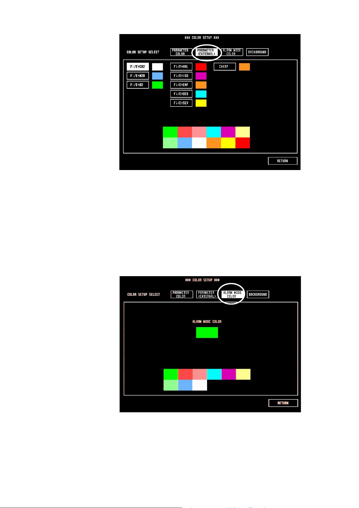
3. CHANGING SYSTEM SETUP SETTINGS
ALARM MODE COLOR
The color for all parameters display can be selected. When ALARM is selected for
the DISPLAY COLOR MODE of the DISPLAY SETUP, all parameters are displayed
in the same color. Available colors are: green, scarlet, pink, sky blue, violet, pale
yellow, pale green, light blue and white.
When an alarm occurs, the alarmed parameter changes to red or yellow according
to the alarm level set at ALARM LEVEL of the ALARM SETUP.
1. Touch the “ALARM MODE COLOR” key.
2. Touch the desired color.
BACKGROUND: BLACK, WHITE
The background color of the monitoring screen can be selected.
3.16 Operator's Manual BSM-2300A
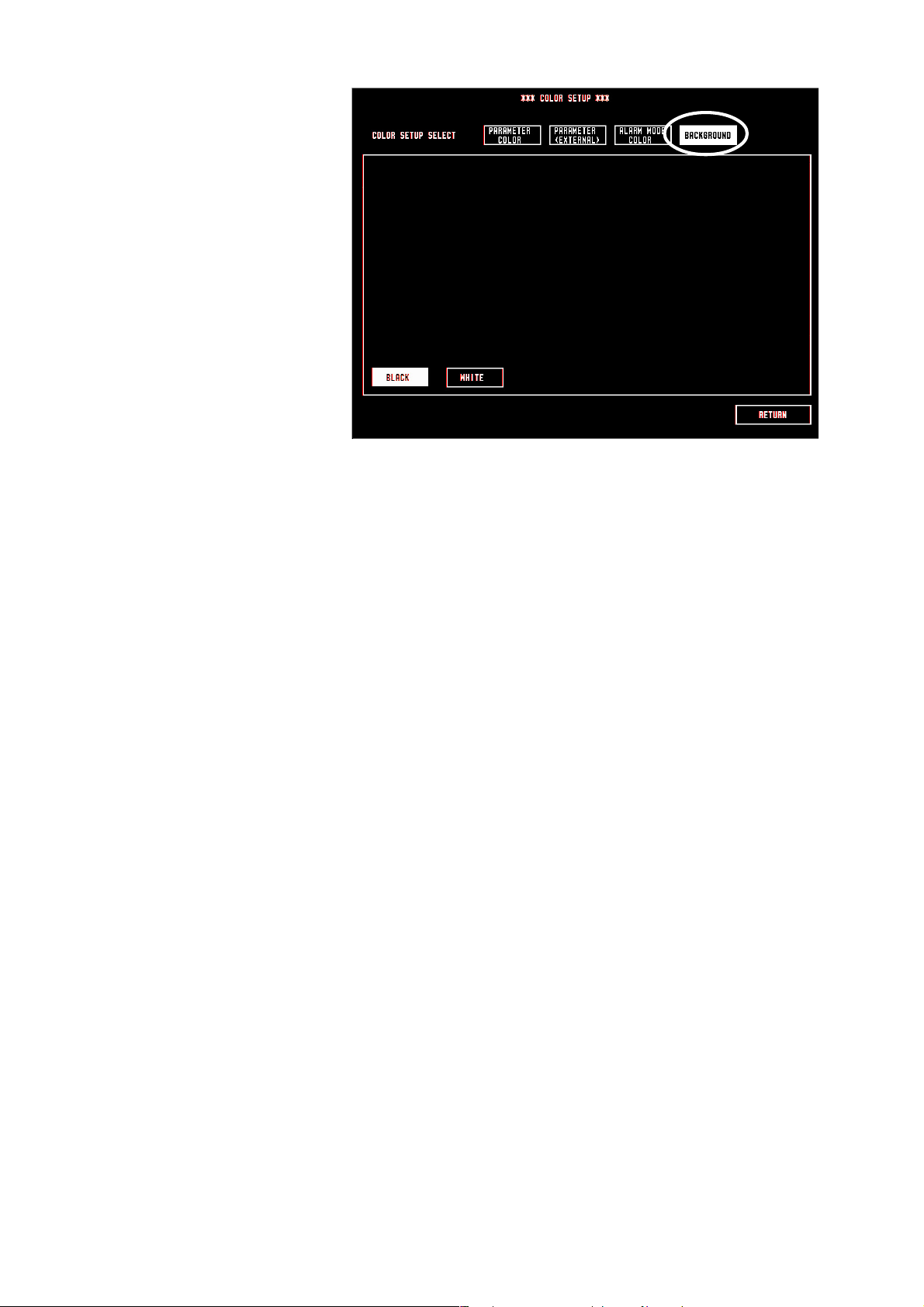
3. CHANGING SYSTEM SETUP SETTINGS
1. Touch the “BACKGROUND” key.
2. Touch the “BLACK” or “WHITE” key.
Operator's Manual BSM-2300A 3.17

3. CHANGING SYSTEM SETUP SETTINGS
Recording Settings
(RECORD SETUP)
These setting items are for when using an optional WS-231P recorder module.
MANUAL RECORD: REAL TIME, DELAY
There are two manual recording modes.
REAL TIME: The beginning of the recorded waveform is when the record key on
the recorder module is pressed.
DELAY: The beginning of the recorded waveform is 8 seconds before the
record key on the recorder module is pressed.
MANUAL RECORD TIME: CONTINUOUS, 10 sec, 20 sec, 30 sec
Select the length for manual recording. When CONTINUOUS is selected, the
recording starts and stops when the record key on the recorder module is pressed.
PERIODIC FREE INTERVAL: 1 to 120 min
You can select the FREE time interval from 1 to 120 min in 1 min steps for
periodic recording. See “Setting Periodic Recording” in Section 8.
1. Enter the numbers by touching the number keys.
2. Touch the “SET” key to enter the value.
3.18 Operator's Manual BSM-2300A
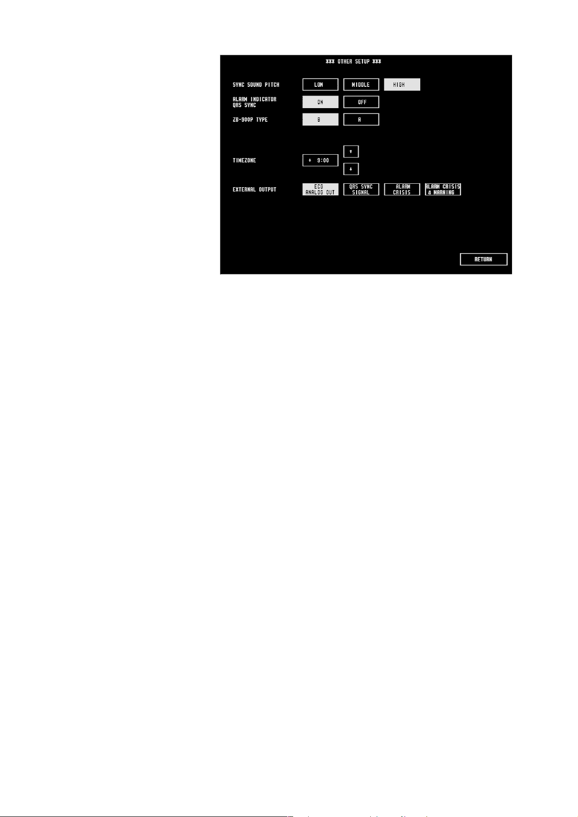
Other Settings
(OTHER SETUP)
3. CHANGING SYSTEM SETUP SETTINGS
SYNC SOUND PITCH: LOW, MIDDLE, HIGH
High, middle, or low pitch synchronized sound can be selected.
ALARM INDICATOR QRS SYNC: ON, OFF
ON: The green lamp blinks in synchronization with the QRS.
OFF: The alarm indicator does not blink.
ZB-900P TYPE: 8, A
Not available.
TIME ZONE: 0 to ±12:00
Set the time zone in respect to GMT (Greenwich Mean Time). The time difference
can be selected in 30 minute steps.
This setting must be the same on all monitors in the same network. Otherwise data
communication problems may occur.
EXTERNAL OUTPUT
Select the type of signal to output from the monitor to the external instrument
connected to the monitor. To output a signal from the monitor, the optional QI-
231P interface is required.
ECG ANALOG OUT: ECG analog signal is output
QRS SYNC SIGNAL: Signal synchronized with QRS is output
ALARM CRISIS: A trigger signal is output when an alarm of crisis
level occurs
ALARM CRISIS & WARNING: A trigger signal is output when an alarm of crisis
or warning level occurs
Operator's Manual BSM-2300A 3.19

3. CHANGING SYSTEM SETUP SETTINGS
Alarm Master Settings
(ALARM MASTER)
For fast and easy alarm setup, a group of alarm items can be set all together at one
time. For example, there may be typical alarm settings at your hospital, or you
may have certain alarm settings for certain patients.
Even when alarms are set by an alarm master, individual alarm settings in the alarm
master can still be changed on the VITAL ALARM or ARRHYTH ALARM window
or the alarm setting in each parameter setup window.
VITAL ALARM MASTER
Set the vital alarm master settings. If the upper limit is set to a value above the
maximum or the lower limit is set to a value below the minimum, the alarm for that
upper/lower limit is automatically set to OFF.
1. Touch the “VITAL” key.
Upper limit
Selected parameter
Alarm limit setting
bar
Lower limit
2. Touch the parameter you want to change the alarm setting for. P2 is not
available on BSM-2301/2351.
3. Touch the “UPPER” key to set the upper limit or touch the “LOWER” key to
set the lower limit.
4. Touch the desired level on the setting bar. Touch the or key to adjust
the setting.
If the upper limit is set to a value above the maximum or the lower limit is set
to a value below the minimum, the alarm is set to OFF.
5. Repeat steps 2 to 4 to change other parameter alarm settings.
ARRHYTHMIA ALARM MASTER
Set the arrhythmia alarm master settings.
1. Touch the “ARRHYTHMIA” key.
3.20 Operator's Manual BSM-2300A
 Loading...