


NEC VT58, VT480, VT57, VT48 User Manual
Portable Projector
VT580/VT480/VT58/VT57/VT48
User’s Manual

© NEC Viewtechnology, Ltd. 2005-2006
2nd edition March 2006
• IBM is a trademark or registered trademark of International Business Machines Corporation.
• Macintosh, Mac OS X and PowerBook are trademarks of Apple Computer, Inc., registered in the U.S. and other
countries.
• Windows, Windows 98, Windows Me, Windows XP or Windows 2000 are trademarks or registered trademarks of
Microsoft Corporation.
• Other product and company names mentioned in this user's manual may be the trademarks or registered trademarks of their respective holders.
NOTES
(1) The contents of this guide may not be reprinted in part or whole without permission.
(2) The contents of this guide are subject to change without notice.
(3) Great care has been taken in the preparation of this manual; however, should you notice any questionable points,
errors or omissions, please contact us.
(4) Notwithstanding article (3), NEC will not be responsible for any claims on loss of profit or other matters deemed to
result from using the Projector.
Important Information
Safety Cautions
Precautions
Please read this manual carefully before using your NEC VT580/VT480/VT58/VT57/VT48 projector and keep the
manual handy for future reference. Your serial number is located on the bottom of your projector. Record it here:
CAUTION
To turn off main power, be sure to remove the plug from power outlet.
The power outlet socket should be installed as near to the equipment as possible, and should be easily
accessible.
CAUTION
TO PREVENT SHOCK, DO NOT OPEN THE CABINET.
THERE ARE HIGH-VOLTAGE COMPONENTS INSIDE.
REFER SERVICING TO QUALIFIED NEC SERVICE PERSONNEL.
This symbol warns the user that uninsulated voltage within the unit may be sufficient to cause electrical
shock. Therefore, it is dangerous to make any kind of contact with any part inside of the unit.
This symbol alerts the user that important information concerning the operation and maintenance of this
unit has been provided.
The information should be read carefully to avoid problems.
WARNING: TO PREVENT FIRE OR SHOCK, DO NOT EXPOSE THIS UNIT TO RAIN OR MOISTURE.
DO NOT USE THIS UNIT’S PLUG WITH AN EXTENSION CORD OR IN AN OUTLET UNLESS ALL THE PRONGS
CAN BE FULLY INSERTED.
DOC Compliance Notice (for Canada only)
This Class B digital apparatus meets all requirements of the Canadian Interference-Causing Equipment Regulations.
Acoustic Noise Information Ordinance-3. GSGV (for Germany only):
The sound pressure level is less than 70 dB (A) according to ISO 3744 or ISO 7779.
CAUTION
Avoid displaying stationary images for a prolonged period of time.
Doing so can result in these images being temporarily sustained on the surface of the LCD panel.
If this should happen, continue to use your projector. The static background from previous images will
disappear.
Disposing of your used product
EU-wide legislation as implemented in each Member State requires that used electrical and electronic
products carrying the mark (left) must be disposed of separately from normal household waste. This
includes projectors and their electrical accessories or lamps. When you dispose of such products, please
follow the guidance of your local authority and/or ask the shop where you purchased the product.
After collecting the used products, they are reused and recycled in a proper way. This effort will help us
reduce the wastes as well as the negative impact such as mercury contained in a lamp to the human
health and the environment at the minimum level.
The mark on the electrical and electronic products only applies to the current European Union Member
States.
i

Important Information
WARNING TO CALIFORNIA RESIDENTS:
Handling the cables supplied with this product, will expose you to lead, a chemical known to the State of California
to cause birth defects or other reproductive harm. Wash hands after handling.
RF Interference (for USA only)
WARNING
The Federal Communications Commission does not allow any modifications or changes to the unit EXCEPT those
specified by NEC Solutions (America), Inc. in this manual. Failure to comply with this government regulation could
void your right to operate this equipment. This equipment has been tested and found to comply with the limits for a
Class B digital device, pursuant to Part 15 of the FCC Rules. These limits are designed to provide reasonable
protection against harmful interference in a residential installation. This equipment generates, uses, and can radiate radio frequency energy and, if not installed and used in accordance with the instructions, may cause harmful
interference to radio communications. However, there is no guarantee that interference will not occur in a particular
installation.
If this equipment does cause harmful interference to radio or television reception, which can be determined by
turning the equipment off and on, the user is encouraged to try to correct the interference by one or more of the
following measures:
• Reorient or relocate the receiving antenna.
• Increase the separation between the equipment and receiver.
• Connect the equipment into an outlet on a circuit different from that to which the receiver is connected.
• Consult the dealer or an experienced radio / TV technician for help.
For UK only: In UK, a BS approved power cable with moulded plug has a Black (five Amps) fuse installed for use with
this equipment. If a power cable is not supplied with this equipment please contact your supplier.
Important Safeguards
These safety instructions are to ensure the long life of your projector and to prevent fire and shock. Please read them
carefully and heed all warnings.
Installation
• Do not place the projector in the following conditions:
- on an unstable cart, stand, or table.
- near water, baths or damp rooms.
- in direct sunlight, near heaters or heat radiating appliances.
- in a dusty, smoky or steamy environment.
- on a sheet of paper or cloth, rugs or carpets.
• If you wish to have the projector installed on the ceiling:
- Do not attempt to install the projector yourself.
- The projector must be installed by qualified technicians in order to ensure proper operation and reduce the
risk of bodily injury.
- In addition, the ceiling must be strong enough to support the projector and the installation must be in accordance with any local building codes.
- Please consult your dealer for more information.
ii
Important Information
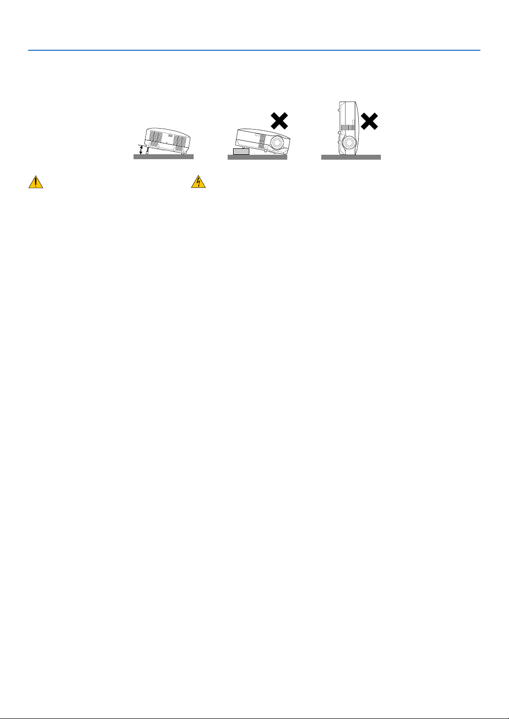
Place the projector in a horizontal position
The tilt angle of the projector should not exceed 10 degrees, nor should the projector be installed in any way other
than the desktop and ceiling mount, otherwise lamp life could decrease dramatically.
10°
Fire and Shock Precautions
• Ensure that there is sufficient ventilation and that vents are unobstructed to prevent the build-up of heat inside your
projector. Allow at least 4 inches (10cm) of space between your projector and a wall.
• Do not try to touch the ventilation outlet on the left front (when seen from the front) as it can become heated while
the projector is turned on and immediately after the projector is turned off.
• Prevent foreign objects such as paper clips and bits of paper from falling into your projector. Do not attempt to
retrieve any objects that might fall into your projector. Do not insert any metal objects such as a wire or screwdriver
into your project. If something should fall into your projector, disconnect it immediately and have the object removed
by a qualified service personnel.
• Do not place any objects on top of the projector.
• Do not touch the power plug during a thunderstorm. Doing so can cause electrical shock or fire.
• The projector is designed to operate on a power supply of 100-240V AC 50/60 Hz. Ensure that your power supply
fits this requirement before attempting to use your projector.
• Do not look into the lens while the projector is on. Serious damage to your eyes could result.
• Keep any items such as magnifying glass out of the light path of the projector. The light being projected from the
lens is extensive, therefore any kind of abnormal objects that can redirect light coming out of the lens, can cause
unpredictable outcome such as fire or injury to the eyes.
• Do not cover the lens with the black lens cap or equivalent while the projector is on. Doing so can lead to melting of
the cap and possibly burning your hands due to the heat emitted from the light output.
• Do not place any objects, which are easily affected by heat, in front of the projector lens or a projector exhaust vent.
Doing so could lead to the object melting or getting your hands burned from the heat that is emitted from the light
output and exhaust.
• Handle the power cable carefully. A damaged or frayed power cable can cause electric shock or fire.
- Do not use any power cables than the supplied one.
- Do not bend or tug the power cable excessively.
- Do not place the power cable under the projector, or any heavy object.
- Do not cover the power cable with other soft materials such as rugs.
- Do not heat the power cable
- Do not handle the power plug with wet hands.
• Turn off the projector, unplug the power cable and have the object removed by a qualified NEC service personnel
under the following conditions:
- When the power cable or plug is damaged or frayed.
- If liquid has been spilled into the projector, or if it has been exposed to rain or water.
- If the projector does not operate normally when you follow the instructions described in this user's manual.
- If the projector has been dropped or the cabinet has been damaged.
- If the projector exhibits a distinct change in performance, indicating a need for service.
- If the projector is not to be used for an extended period of time.
• Disconnect the power cable and any other cables before carrying the projector
• Turn off the projector and unplug the power cable before cleaning the cabinet or replacing the lamp.
iii
Important Information
CAUTION
• Do no use the tilt-foot for purposes other than originally intended. Misuses such as gripping the tilt-foot or
hanging on the wall can cause damage to the projector.
• Do not send the projector in the soft case by parcel delivery service or cargo shipment. The projector inside
the soft case could be damaged.
• When carrying the projector by the carrying handle, make sure the two screws that attach the carrying handle
to the projector cabinet are tight.
Insufficient tightening of the two screws could result in the projector falling and causing injury.
• Select [High] in Fan mode if you continue to use the projector for consecutive days. (From the menu, select
[Setup] → [Options] → [Fan Mode] → [High].)
• Do not turn off the AC power by pressing the main power switch or by unplugging the power cable when the
projector is powered on.
• Do not turn off the AC power for 60 seconds after the lamp is turned on and while the POWER indicator is blinking
green.Doing so could cause premature lamp failure.
Remote Control Precautions
• Handle the remote control carefully.
• If the remote control gets wet, wipe it dry immediately.
• Avoid excessive heat and humidity.
• Do not heat, take apart, or throw batteries into fire.
• If you will not be using the remote control for a long time,remove the batteries.
• Ensure that you have the batteries’ polarity (+/-) aligned correctly.
• Do not use new and old batteries together, or use different types of batteries together.
• Dispose of used batteries according to your local regulations.
Lamp Replacement
• To replace the lamp, follow all instructions provided on page 51.
• Be sure to replace the lamp when the message [The lamp has reached the end of its usable life. Please
replace the lamp.] appears. If you continue to use the lamp after the lamp has reached the end of its usable
life, the lamp bulb may shatter, and pieces of glass may be scattered in the lamp case. Do not touch them as
the pieces of glass may cause injury.
If this happens, contact your dealer for lamp replacement.
A Lamp Characteristic
The projector has a high-pressure mercury lamp as a light source.
A lamp has a characteristic that its brightness gradually decreases with age. Also repeatedly turning the lamp on
and off will increase the possibility of its lower brightness.
CAUTION:
When removing the lamp from a ceiling-mounted projector, make sure that no one is under the projector. Glass
fragments could fall if the lamp has been burned out.
iv

Table of Contents
Important Information ----------------------------------------------------------- i
1. Introduction ---------------------------------------------------------------------- 1
What's in the Box? --------------------------------------------------------------------------------- 1
Introduction to the Projector --------------------------------------------------------------------- 2
Part Names of the Projector --------------------------------------------------------------------- 3
Attaching the supplied carrying handle ---------------------------------------------------- 4
Top Features-------------------------------------------------------------------------------------- 5
Terminal Panel Features----------------------------------------------------------------------- 6
Part Names of the Remote Control ------------------------------------------------------------ 7
Battery Installation ------------------------------------------------------------------------------ 8
Remote Control Precautions ----------------------------------------------------------------- 8
Operating Range for Wireless Remote Control ------------------------------------------ 8
2. Installation and Connections ------------------------------------------- 9
Setting Up the Screen and the Projector ----------------------------------------------------- 9
Selecting a Location (VT580/VT480/VT58/VT57) --------------------------------------- 9
Selecting a Location (VT48) ---------------------------------------------------------------- 10
Throw Distance and Screen Size ----------------------------------------------------------11
Making Connections ----------------------------------------------------------------------------- 13
Enabling the computer’s external display ----------------------------------------------- 13
Connecting Your PC or Macintosh Computer ------------------------------------------ 13
To connect SCART output (RGB) --------------------------------------------------------- 14
Connecting an External Monitor ----------------------------------------------------------- 15
Connecting Your DVD Player with Component Output ------------------------------ 16
Connecting Your VCR or Laser Disc Player -------------------------------------------- 17
Connecting the Supplied Power Cable -------------------------------------------------- 18
3. Projecting an Image (Basic Operation)-------------------------- 19
Turning on the Projector ------------------------------------------------------------------------ 19
Note on Startup screen (Menu Language Select screen) --------------------------- 20
Selecting a Source ------------------------------------------------------------------------------- 21
Adjusting the Picture Size and Position----------------------------------------------------- 22
Correcting Keystone Distortion --------------------------------------------------------------- 24
Optimizing RGB Picture Automatically ------------------------------------------------------ 26
Turning Up or Down Volume------------------------------------------------------------------- 26
Turning off the Projector ------------------------------------------------------------------------ 27
After Use -------------------------------------------------------------------------------------------- 28
v

Table of Contents
4. Convenient Features ------------------------------------------------------ 29
Turning off the Image and Sound ------------------------------------------------------------ 29
Freezing a Picture -------------------------------------------------------------------------------- 29
Enlarging a Picture ------------------------------------------------------------------------------- 29
Changing Lamp Mode--------------------------------------------------------------------------- 30
Preventing the Unauthorized Use of the Projector --------------------------------------- 30
Using Remote Mouse Receiver (VT580/VT480 only) ----------------------------------- 33
5. Using On-Screen Menu --------------------------------------------------- 35
Using the Menus---------------------------------------------------------------------------------- 35
Menu Elements ----------------------------------------------------------------------------------- 37
List of Menu Items-------------------------------------------------------------------------------- 38
Menu Descriptions & Functions [Picture] --------------------------------------------------- 40
Menu Descriptions & Functions [Image Options] ---------------------------------------- 41
Menu Descriptions & Functions [Setup] ---------------------------------------------------- 43
Menu Descriptions & Functions [Information] --------------------------------------------- 47
Menu Descriptions & Functions [Reset] ---------------------------------------------------- 48
6. Maintenance ------------------------------------------------------------------- 49
Cleaning or Replacing the Filters------------------------------------------------------------- 49
Cleaning the Cabinet and the Lens ---------------------------------------------------------- 50
Replacing the Lamp ----------------------------------------------------------------------------- 51
7. Appendix ------------------------------------------------------------------------- 54
Troubleshooting ----------------------------------------------------------------------------------- 54
Specifications-------------------------------------------------------------------------------------- 57
Cabinet Dimensions ----------------------------------------------------------------------------- 59
Pin Assignments of D-Sub COMPUTER Input Connector ----------------------------- 60
Compatible Input Signal List ------------------------------------------------------------------- 61
PC Control Codes and Cable Connection ------------------------------------------------- 62
Troubleshooting Check List -------------------------------------------------------------------- 64
TravelCare Guide--------------------------------------------------------------------------------- 66
vi
1. Introduction
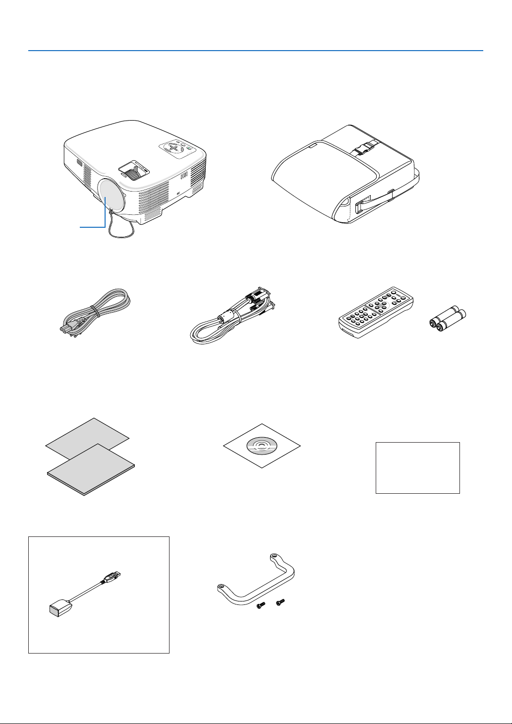
What's in the Box?
Make sure your box contains everything listed. If any pieces are missing, contact your dealer.
Please save the original box and packing materials if you ever need to ship your projector.
Projector
J.
D
O A
T
AU
E
C
R
T
I
U
X
E
O
S
Y
B
D
N
A
T
S
/
T
N
C
O
E
EL
S
R
E
T
U
N
N
E
E
M
R
E
W
O
S
P
U
T
A
T
S
P
M
A
L
M
O
ZO
CUS
FO
Lens cap
(24FT9641)
Soft case
(24BS7581)
M
E
N
U
ENTER
L
C
L
IC
K
V
ID
E
X
E
I
O
M
T
O
U
S
C
-V
S
O
E
R
ID
M
-
P
C
E
U
L
O
T
I
1
C
E
R
K
V
O
A
L
U
U
T
O
M
A
E
2
D
J
.
L
A
A
S
M
P
P
E
M
C
O
T
D
P
E
I
C
T
H
U
E
R
L
E
P
F
R
E
E
Z
E
O
F
F
M
A
G
N
I
P
F
O
Y
W
P
E
IC
R
O
M
N
U
T
E
P
A
G
E
U
P
D
O
W
N
Power cable
(US: 7N080220)
(EU: 7N080007)
Quick Setup Guide
Important Information
For VT580 and VT480 only
Remote mouse receiver
(7N900721)
VGA signal cable
(7N520054)
CD-ROM
User’s manual
Carrying handle (24FT9651)
Screw (M4⳯2: 24V00411)
Remote control
(7N900731)
For North America only
Registration card
Limited warranty
For Europe only
Guarantee policy
Batteries (AAA⳯2)
1

1. Introduction
Introduction to the Projector
This section introduces you to your new projector and describes the features and controls.
Congratulations on Your Purchase of the Projector
This projector is one of the very best projectors available today. The projector enables you to project precise images
up to 300 inches across (measured diagonally) from your PC or Macintosh computer (desktop or notebook), VCR,
DVD player, document camera, or a laser disc player.
You can use the projector on a tabletop or cart, you can use the projector to project images from behind the screen,
and the projector can be permanently mounted on a ceiling*1. The remote control can be used wirelessly.
1
Do not attempt to mount the projector on a ceiling yourself.
*
The projector must be installed by qualified technicians in order to ensure proper operation and reduce the
risk of bodily injury.
In addition, the ceiling must be strong enough to support the projector and the installation must be in accordance with any local building codes. Please consult your dealer for more information.
Features you'll enjoy:
• Auto vertical keystone correction up to +/– 30 degrees (VT580 only)
• Built-in Wall Color Correction presets provide for adaptive color correction when projecting onto non-white
screen material
• Quick start & quick cool down
Eight seconds after turning on the power, the projector is ready to display PC or video images.
Powering down; The fans stop 30 seconds after turning off the power from the remote control or cabinet control
panel. The projector can be put away immediately after the projector is powered down.
Also, the main power of the projector can be turned off by pressing the main power switch or unplugging the
power cable even during the cool down period after the projector is turned off.
• HDTV (1080i, 720p) and SDTV (576p, 480p) compatibility
• Color Management system
• Short focal length lens
• Display popular wide screen and full screen aspect ratios – 16:9 and 4:3
• Built-in speaker for an integrated audio solution
• High resolution display - up to UXGA compatible, XGA native resolution (SVGA: VT480 and VT48).
• Multiple video mode selections (depending on your source)
• Security feature prevents unauthorized individuals from displaying images.
• You can control the projector with a PC or control system using the PC Control port.
• Easy set up and operation
• The contemporary cabinet design is light, compact and complements any office, boardroom Auditorium.
• You can use the supplied wireless remote control and remote mouse receiver to operate your PC mouse from
across the room. The remote mouse receiver supports almost any PC using a USB connection (VT580 and
VT480 only).
About this user's manual
The fastest way to get started is to take your time and do everything right the first time. Take a few minutes now to
review the user's manual. This may save you time later on. At the beginning of each section of the manual you'll find
an overview. If the section doesn't apply, you can skip it.
2
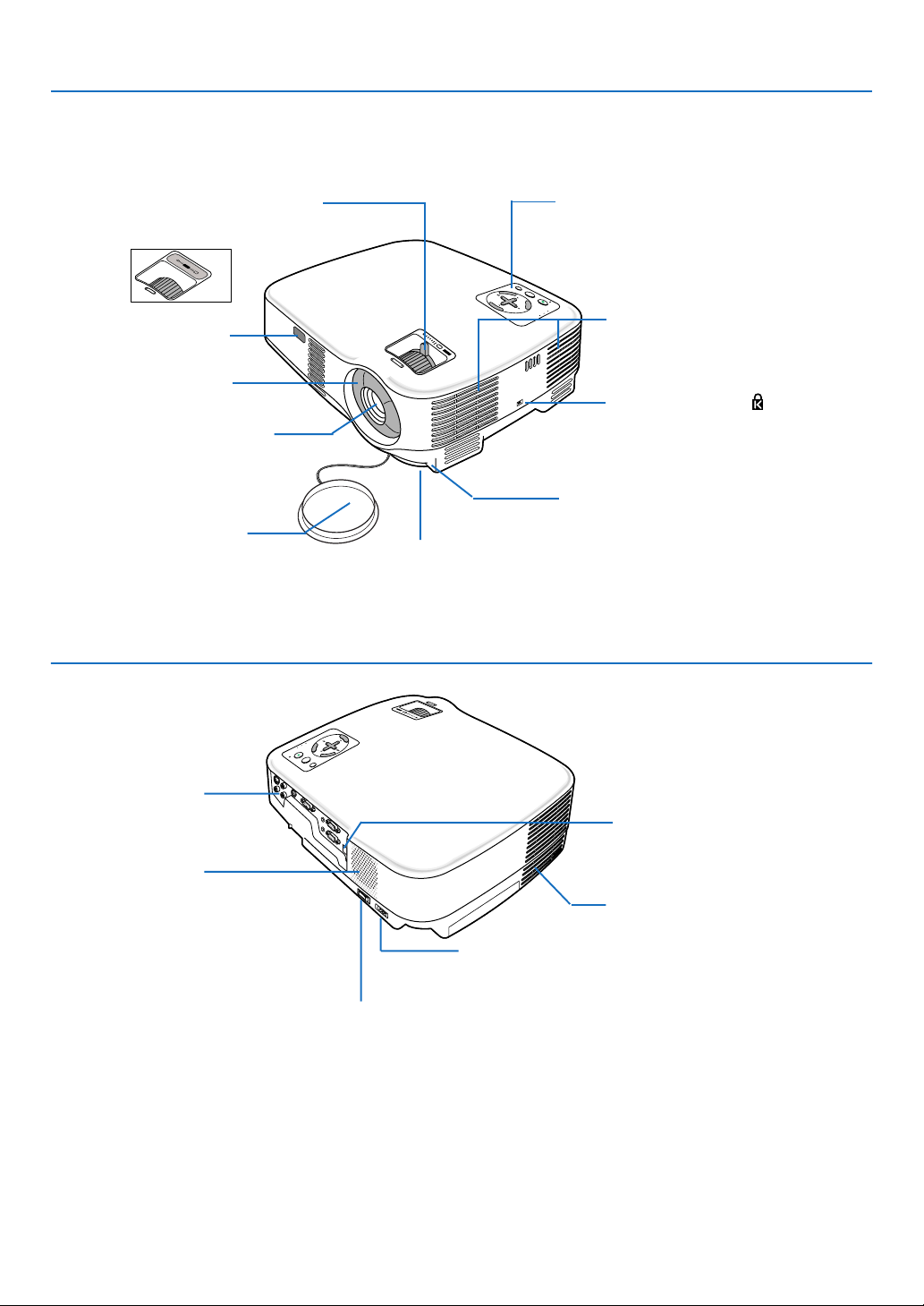
Part Names of the Projector
Front/Top
1. Introduction
Zoom Lever (VT580/VT480/VT58/VT57)
Digital Zoom Button (VT48)
Controls
(→ page 5)
(→ page 23)
M
O
O
Z
ADJ.
S
U
C
O
F
Remote sensor
(→ page 8)
Focus Ring
(→ page 23)
M
O
O
S
Z
U
C
O
F
AUTO
E
C
R
T
I
U
X
E
O
S
BY
TAND
T
N/S
C
O
E
L
E
S
R
TE
NU
N
E
E
M
R
E
W
O
S
P
U
T
A
T
S
P
M
A
L
Ventilation (inlet) / Filter Cover
(→ page 49)
Two filters on VT580 and VT480
One filter on VT58, VT57 and VT48
Built-in Security Slot ( )*
Lens
Adjustable Tilt Foot Button
(→ page 22)
Lens Cap
Adjustable Tilt Foot
(→ page 22)
* This security slot supports the MicroSaver ® Security System. MicroSaver ® is a registered trademark of
Kensington Microware Inc. The logo is trademarked and owned by Kensington Microware Inc.
Rear
F
O
C
U
S
Z
O
O
M
M
E
N
U
S
L
E
A
E
L
M
E
P
N
C
S
T
T
T
A
T
E
U
P
R
O
S
W
E
R
T
I
X
E
O
N
/S
T
A
N
D
B
Y
S
O
U
R
C
E
A
U
T
O
A
D
J
.
Terminal Panel
(→ page 6)
Remote sensor (VT580 and VT480 only)
(→ page 8)
Monaural Speaker
(1W)
Ventilation (outlet)
Heated air is exhausted from here.
AC Input
Connect the supplied power cable's two-pin plug here, and
plug the other end into an active wall outlet. (→ page 18)
Main Power Switch
When you plug the supplied power cable into an active wall outlet
and turn on the Main Power, the POWER indicator turns orange
and the projector is in standby mode.
(→ page 19)
3
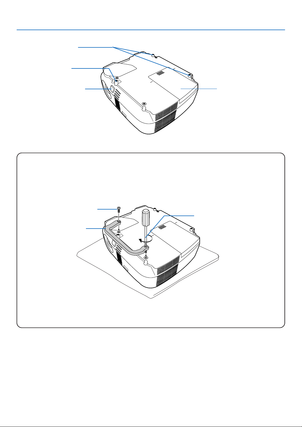
Bottom
Rear Foot (Left / Right)
(→ page 22)
Adjustable Tilt Foot
(→ page 22)
1. Introduction
Adjustable Tilt Foot Button
(→ page 22)
Lamp Cover
(→ page 51)
Attaching the supplied carrying handle
You can carry the projector by attaching the supplied carrying handle securely to the projector.
To attach the supplied carrying handle, use a Phillips-head screwdriver and the supplied two screws.
Place a soft cloth on the working surface before turning the projector over to prevent scratching the top cover.
Make sure that the carrying handle is attached with correct orientation as shown below.
Screw
Phillips-head screwdriver
(not supplied)
Carrying handle
CAUTION
When carrying the projector by the carrying handle, make sure the two screws that attach the carrying handle
to the projector cabinet are tight.
4
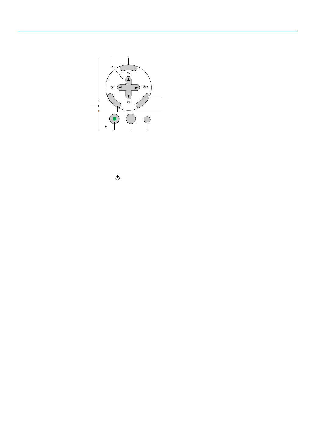
Top Features
1. Introduction
1
ENTER
LAMP
STATUS
2
POWER
ON/STAND BY
4
3
1. LAMP Indicator (→page 51,54)
2. STATUS Indicator (→page 54)
3. POWER Indicator (→page 19,27,54)
4. POWER Button (ON / STAND BY) (
(→page 19,27)
5. SOURCE Button
6. AUTO ADJ. Button (→page 26)
7. MENU Button
8. SELECT / Volume Buttons /
Keystone Buttons
9. ENTER Button
10. EXIT Button
)
78
MENU
SELECT
5 6
XIT
E
10
9
AUTO ADJ.SOURCE
5
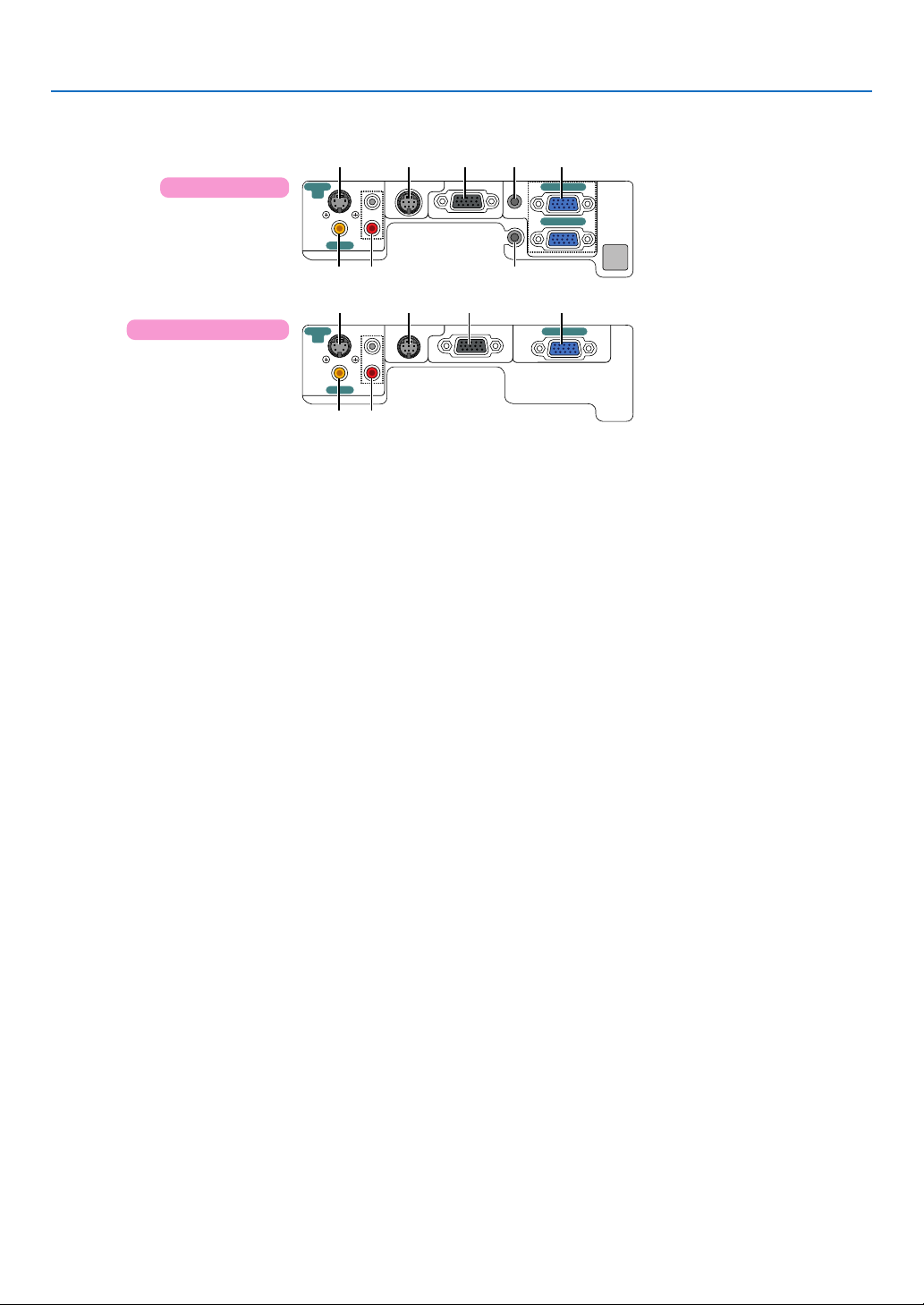
Terminal Panel Features
VT580/VT480
VT58/VT57/VT48
S-VIDEO
IN
S-VIDEO
IN
VIDEO IN
VIDEO IN
L
R
AUDIO IN
L
R
AUDIO IN
PC CONTROL
PC CONTROL
76
1. COMPUTER 1 and 2 IN/ Component Input
Connector (Mini D-Sub 15 Pin)
(VT580/VT480) (→page 13,14,16)
COMPUTER IN/ Component Input Connector
(Mini D-Sub 15 Pin)
(VT58/VT57/VT48) (→page 13,14,16)
2. AUDIO IN Mini Jack (Stereo Mini) (→page 13,15,16)
(Not available on VT58/VT57/VT48)
3. AUDIO OUT Mini Jack (Stereo Mini) (→page 15)
(Not available on VT58/VT57/VT48)
4. MONITOR OUT Connector (Mini D-Sub 15 Pin)
(→page 15)
5. S-VIDEO IN Connector (Mini DIN 4 Pin)
(→page 17)
6. VIDEO IN Connector (RCA) (→page 17)
7. AUDIO Input Jacks L/R (RCA) (→page 17)
8. PC CONTROL Port (DIN 8 Pin) (→page 62,63)
Use this port to connect a PC or control system.
This enables you to control the projector using serial
communication protocol. If you are writing your own
program, typical PC control codes are on page 62.
MONITOR OUT(COMP 1)
AUDIO IN
AUDIO OUT
376
MONITOR OUT
1. Introduction
1485 2
COMPUTER 1 IN
COMPUTER 2 IN
1485
COMPUTER IN
6
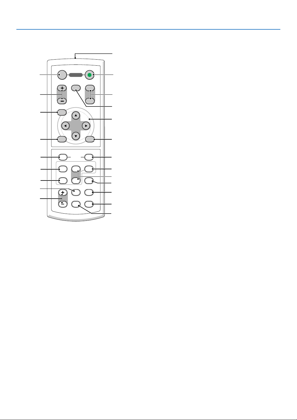
Part Names of the Remote Control
1
1. Introduction
OFF
3
MAGNIFY PAGE
PIC-MUTE
4
7
MENU
POWER
ON
UP
DOWN
2
6
5
8
9
11
13
14
19
17
ENTER
L-CLICK
VIDEO
S-VIDEO
VOLUME
COMPUTER
EXIT
R-CLICK
MOUSE
COMPUTER
AUTO ADJ.
1
LAMP MODE
2
ASPECT HELP
FREEZEPICTURE
10
12
16
15
18
21
22
20
1. Infrared Transmitter
(→ page 8)
2. POWER ON Button
(→ page 19)
3. POWER OFF Button
(→ page 27)
4. MAGNIFY (+)(–) Button
(→ page 29)
5. PIC-MUTE Button
(→ page 29)
6. PAGE UP/DOWN Button*
(Not available on VT58, VT57 and VT48)
(→ page 33,34)
7. MENU Button
8. SELECT Button
9. ENTER Button
10. EXIT Button
11. MOUSE L-CLICK Button*
(Not available on VT58, VT57 and VT48)
(→ page 33,34)
* The PAGE UP/DOWN, MOUSE L-CLICK and MOUSE R-CLICK buttons work only when the supplied remote mouse
receiver is connected with your computer.
12. MOUSE R-CLICK Button*
(Not available on VT58, VT57 and VT48)
(→ page 33,34)
13. VIDEO Button
(→ page 21)
14. S-VIDEO Button
(→ page 21)
15. COMPUTER 1/2 Button
(The COMPUTER 2 button is not available on
VT58, VT57 and VT48)
(→ page 21)
16. AUTO ADJ. Button
(→ page 26)
17. VOLUME (+)(–) Button
(→ page 26)
18. LAMP MODE Button (→ page 30)
19. ASPECT Button
(→ page 41)
20. PICTURE Button
(→ page 40 to 41)
21. HELP Button
(→ page 47)
22. FREEZE Button
(→ page 29)
7
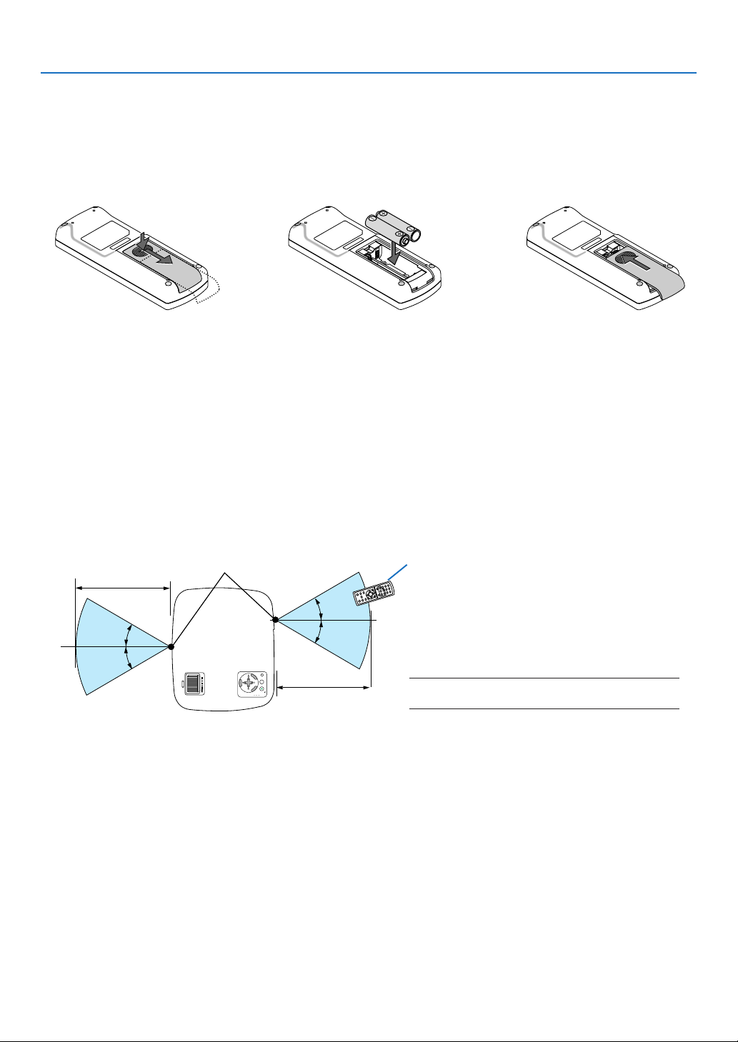
Battery Installation
1. Introduction
1
Press firmly and slide the
battery cover off.
2
Install new batteries (AAA).
Ensure that you have the
batteries' polarity (+/–) aligned
correctly.
3
Slip the cover back over the batteries until it snaps into place. Do
not mix different types of batteries or new and old batteries.
Remote Control Precautions
• Handle the remote control carefully.
• If the remote control gets wet, wipe it dry immediately.
• Avoid excessive heat and humidity.
• Do not heat, take apart, or throw batteries into fire.
• If you will not be using the remote control for a long time, remove the batteries.
• Ensure that you have the batteries’ polarity (+/-) aligned correctly.
• Do not use new and old batteries together, or use different types of batteries together.
• Dispose of used batteries according to your local regulations.
Operating Range for Wireless Remote Control
Remote sensor on projector cabinet
Remote control
7m/22 feet
30°
30°
30°
(*)
EXIT
AUTO ADJ.SOURCE
MENU
FOCUS
ZOOM
SELECT
ENTER
ON/STAND BY
LAMP
STATUS
POWER
30°
7m/22 feet
*NOTE: The VT58, VT57 and VT48 do not have the
remote sensor on the rear panel.
• The infrared signal operates by line-of-sight up to a distance of about 22 feet/7 m and within a 60-degree angle of
the remote sensor on the projector cabinet.
• The projector will not respond if there are objects between the remote control and the sensor, or if strong light falls
on the sensor. Weak batteries will also prevent the remote control from properly operating the projector.
8
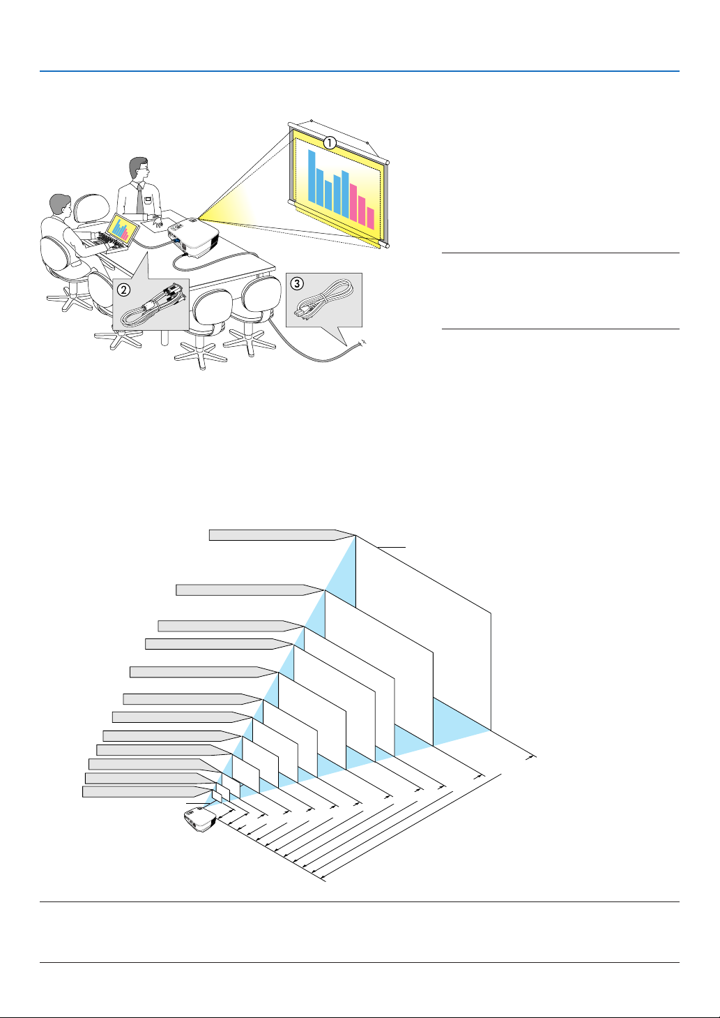
2. Installation and Connections
This section describes how to set up your projector and how to connect video and audio sources.
Your projector is simple to set up and use. But before you get started, you must first:
1 Set up a screen and the projector.
2 Connect your computer or video equip-
ment to the projector. (→ pages 13 to 17)
F
O
C
U
S
Z
O
O
M
M
E
N
U
S
L
E
A
E
L
M
E
P
N
C
S
T
T
T
A
T
E
U
P
O
R
S
W
E
R
T
I
X
E
O
N
/
S
T
A
N
D
B
Y
S
O
U
R
C
E
A
U
T
O
A
D
J
.
To the wall outlet.
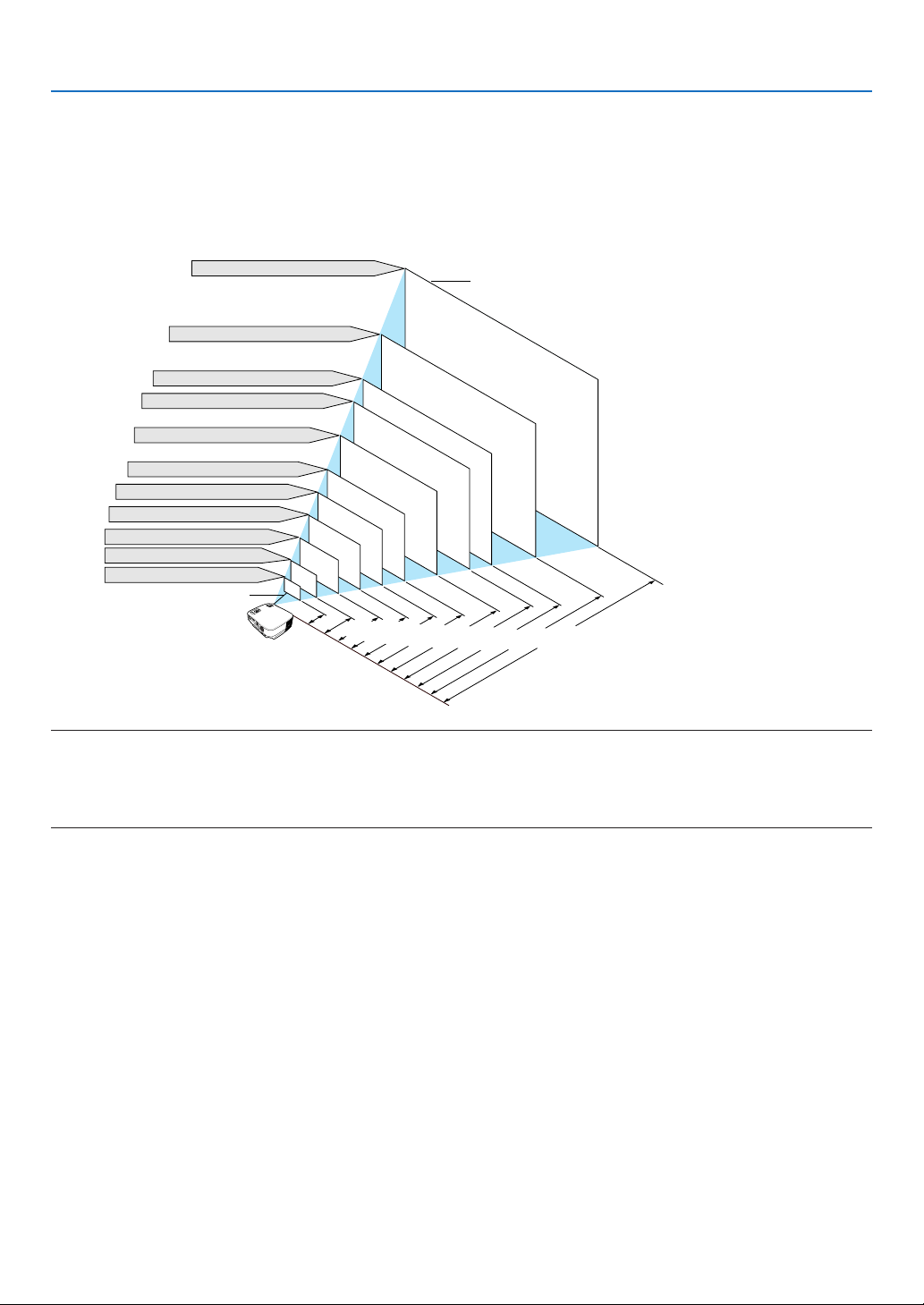
Setting Up the Screen and the Projector
Selecting a Location (VT580/VT480/VT58/VT57)
The further your projector is from the screen or wall, the larger the image. The minimum size the image can be is
approximately 21" (0.53 m) measured diagonally when the projector is roughly 30 inches (0.8 m) from the wall or
screen. The largest the image can be is 300" (7.6 m) when the projector is about 400 inches (10 m) from the wall or
screen.
Screen Size (Unit: cm/inch)
609.6(W)⳯457.2(H) / 240(W)⳯180(H)
300"
3 Connect the supplied power cable.
(→ page 18)
NOTE: Ensure that the power cable and any
other cables are disconnected before moving
the projector. When moving the projector or
when it is not in use, cover the lens with the
lens cap.
Screen Size
487.7(W)⳯365.8(H) / 192(W)⳯144(H)
240
"
406.4(W)⳯304.8(H) / 160(W)⳯120(H)
365.8(W)⳯274.3(H) / 144(W)⳯108(H)
200
180"
"
304.8(W)⳯228.6(H) / 120(W)⳯90(H)
150"
243.8(W)⳯182.9(H) / 96(W)⳯72(H)
203.2(W)⳯152.4(H) / 80(W)⳯60(H)
162.6(W)⳯121.9(H) / 64(W)⳯48(H)
121.9(W)⳯91.4(H) / 48(W)⳯36(H)
81.3(W)⳯61.0(H) / 32(W)⳯24(H)
61.0(W)⳯45.7(H) / 24(W)⳯18(H)
42.7(W)⳯32(H) / 17(W)⳯13(H)
Lens center
30"
21"
F
O
C
U
S
M
E
N
U
S
L
ELE
A
E
MP
N
C
S
T
T
T
A
TU
E
P
O
S
R
W
ER
0.8/
T
I
X
E
O
N
/
S
T
A
N
D
B
Y
S
O
U
R
C
E
A
U
T
O
A
D
J
.
30
40"
1.0/39
60"
80"
1.3/
120"
100"
53
2.0/80
2.7/106
3.4/133
4.1/160
5.1/200
6.1/240
ta
is
D
6.8/267
(U
e
c
n
n
it: m
8.1/321
c
/in
10.2/402
)
h
TIP:
• The distances are indicated by intermediate values between tele and wide. Use as a rule of thumb.
• The Zoom lever adjusts the image size +/-10%
• For more details on throw distance, see page 11.
9
2. Installation and Connections
Selecting a Location (VT48)
The further your projector is from the screen or wall, the larger the image. The minimum size the image can be is
approximately 25" (0.64 m) measured diagonally when the projector is roughly 35 inches (0.9 m) from the wall or
screen. The largest the image can be is 300" (7.6 m) when the projector is about 434 inches (11.0 m) from the wall or
screen. Use the drawing below as a guide.
Screen Size (Unit: cm/inch)
609.6(W)⳯457.2(H) / 240(W)⳯180(H)
300
Screen Size
"
487.7(W)⳯365.8(H) / 192(W)⳯144(H)
240
"
406.4(W)⳯304.8(H) / 160(W)⳯120(H)
100
"
"
1.4/57
120
"
180
150
"
2.2/86
200
"
"
"
2.9/115
3.7/144
4.4/173
5.5/217
6.6/260
7.3/289
11.0/434
8.8/347
365.8(W)⳯274.3(H) / 144(W)⳯108(H)
304.8(W)⳯228.6(H) / 120(W)⳯90(H)
243.8(W)⳯182.9(H) / 96(W)⳯72(H)
203.2(W)⳯152.4(H) / 80(W)⳯60(H)
162.6(W)⳯121.9(H) / 64(W)⳯48(H)
121.9(W)⳯91.4(H) / 48(W)⳯36(H)
81.3(W)⳯61.0(H) / 32(W)⳯24(H)
50.8(W)⳯38.1(H) / 20(W)⳯15(H)
Lens center
S
L
E
A
E
L
M
E
P
N
C
S
T
T
T
A
T
E
U
P
R
OW
S
E
R
T
I
X
E
O
N
/
S
T
A
N
D
B
Y
S
O
U
R
C
E
A
U
T
O
A
D
J
.
80
60
40
"
25"
F
O
C
U
S
M
E
N
U
0.9/
35
Distance (Unit: m/inch)
TIP:
• The distances are indicated by intermediate values between tele and wide. Use as a rule of thumb.
• Digital Zoom can result in a blurry image due to the electronic zoom.
• The Zoom button adjusts the image size -10%
• For more details on throw distance, see next page.
10
2. Installation and Connections
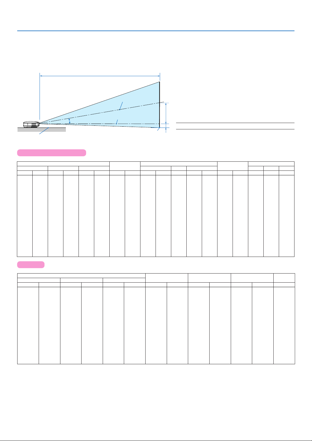
Throw Distance and Screen Size
The following shows the proper relative positions of the projector and screen. Refer to the table to determine the
position of installation.
Distance Chart
Projector bottom
C
Screen center
α
Lens center
Screen bottom
B = Vertical distance between lens center and
screen center
C = Throw distance
D = Vertical distance between lens center and
screen bottom (top of screen for ceiling
application)
α = Throw angle
B
D
NOTE: Distances may vary +/-5%.
VT580/VT480/VT58/VT57
inch
100
120
150
180
200
210
240
270
300
21
25
30
40
60
72
80
84
90
Diagonal
mm
533
635
762
1016
1524
1829
2032
2134
2286
2540
3048
3810
4572
5080
5334
6096
6858
7620
Screen Size C α
Width Height wide tele wide tele
inch
mm
inch
120
144
160
168
192
216
240
17
427
20
508
24
610
32
813
48
1219
58
1463
64
1626
67
1707
72
1829
80
2032
96
2438
3048
3658
4064
4267
4877
5486
6096
108
120
126
144
162
180
mm
13
320
15
381
18
457
24
610
36
914
43
1097
48
1219
50
1280
54
1372
60
1524
72
1829
90
2286
2743
3048
3200
3658
4115
4572
inch
B
mm
inch
mm
-
inch
104
116
122
131
145
174
218
262
291
306
350
394
438
mm
30
750
35
900
43
1090
57
1460
87
2200
2650
2940
3090
3310
3690
4430
5540
6660
7400
7770
8890
10000
11120
4
110
-
-
5
140
160
220
320
390
430
450
490
540
650
810
970
1080
1140
1300
1460
1620
101
109
121
145
182
218
243
255
291
328
365
29
35
48
72
87
96
6
9
13
15
17
18
19
21
26
32
38
43
45
51
57
64
740
900
1210
1830
2200
2450
2570
2760
3070
3690
4620
5540
6160
6470
7400
8330
9260
-
-
-
-
-
-
-
-
-
-
-
-
-
-
-
-
-
-
inch
-10
-13
-16
-17
-18
-21
-24
-26
D
mm
-130
-160
-180
-190
-200
-220
-270
-330
-400
-440
-460
-530
-600
-660
degree
-50
-60
-70
-90
-2
-2
-3
-3
-5
-6
-7
-7
-8
-9
10.3
10.2
10.1
10.1
10.0
10.0
10.0
10.0
10.0
10.0
10.0
10.0
10.0
10.0
-
degree
-
-
9.9
9.9
9.9
8.6
-
8.5
-
8.5
-
8.4
-
8.4
-
8.4
-
8.4
-
8.4
-
8.4
-
8.3
-
8.3
-
8.3
-
8.3
-
8.3
-
8.3
-
8.3
-
8.3
-
8.3
VT48
Diagonal
inch
25
30
40
60
72
80
84
90
100
120
150
180
200
210
240
270
300
mm
635
762
1016
1524
1829
2032
2134
2286
2540
3048
3810
4572
5080
5334
6096
6858
7620
Screen Size
Width Height
inch
120
144
160
168
192
216
240
20
24
32
48
58
64
67
72
80
96
mm
508
610
813
1219
1463
1626
1707
1829
2032
2438
3048
3658
4064
4267
4877
5486
6096
inch
108
120
126
144
162
180
DCB
15
18
24
36
43
48
50
54
60
72
90
mm
381
457
610
914
1097
1219
1280
1372
1524
1829
2286
2743
3048
3200
3658
4115
4572
inch
5
6
9
13
15
17
18
19
21
26
32
38
43
45
51
57
64
mm
140
160
220
320
390
430
450
490
540
650
810
970
1080
1140
1300
1460
1620
inch
103
115
121
129
144
173
217
260
289
304
347
391
434
35
42
57
86
mm
890
1070
1440
2180
2620
2920
3060
3290
3650
4390
5500
6610
7340
7710
8820
9930
11030
inch
-10
-13
-16
-17
-18
-21
-24
-26
-2
-3
-3
-5
-6
-7
-7
-8
-9
mm
-60
-70
-90
-130
-160
-180
-190
-200
-220
-270
-330
-400
-440
-460
-530
-600
-660
α
degree
8.7
8.6
8.5
8.5
8.4
8.4
8.4
8.4
8.4
8.4
8.4
8.4
8.4
8.4
8.4
8.4
8.4
11

2. Installation and Connections
WARNING
* Installing your projector on the ceiling must be done
by a qualified technician. Contact your NEC dealer
for more information.
* Do not attempt to install the projector yourself.
• Only use your projector on a solid, level surface. If the
projector falls to the ground, you can be injured and
the projector severely damaged.
• Do not use the projector where temperatures vary
greatly. The projector must be used at temperatures
between 41˚F (5˚C) and 104˚F (40˚C) (Eco mode
selected automatically at 95˚F to 104˚F/35˚C to 40˚C).
• Do not expose the projector to moisture, dust, or
smoke. This will harm the screen image.
• Ensure that you have adequate ventilation around your
projector so heat can dissipate. Do not cover the vents
on the side or the front of the projector.
Reflecting the Image
Using a mirror to reflect your projector’s image enables
you to enjoy a much larger image when a smaller space
is required. Contact your NEC dealer if you need a mirror
system. If you're using a mirror system and your image
is inverted, use the MENU and SELECT buttons on your
projector cabinet or your remote control to correct the
orientation. (→ page 44)
12
L
COMPUTER IN
MONITOR OUT
AUDIO IN
S-VIDEO
IN
VIDEO IN
PC CONTROL
R
COMPUTER IN
2. Installation and Connections
Making Connections
NOTE: When using with a notebook PC, be sure to connect the projector and notebook PC while the projector is in standby mode
and before turning on the power to the notebook PC.
In most cases the output signal from the notebook PC is not turned on unless connected to the projector before being powered
up.
* If the screen goes blank while using your remote control, it may be the result of the computer's screen-saver or power
management software.
Enabling the computer’s external display
Displaying an image on the notebook PC’s screen does not necessarily mean it outputs a signal to the projector.
When using a PC compatible laptop, a combination of function keys will enable/disable the external display.
Usually, the combination of the ‘Fn” key along with one of the 12 function keys gets the external display to come on or
off. For example, NEC laptops use Fn + F3, while Dell laptops use Fn + F8 key combinations to toggle through
external display selections.
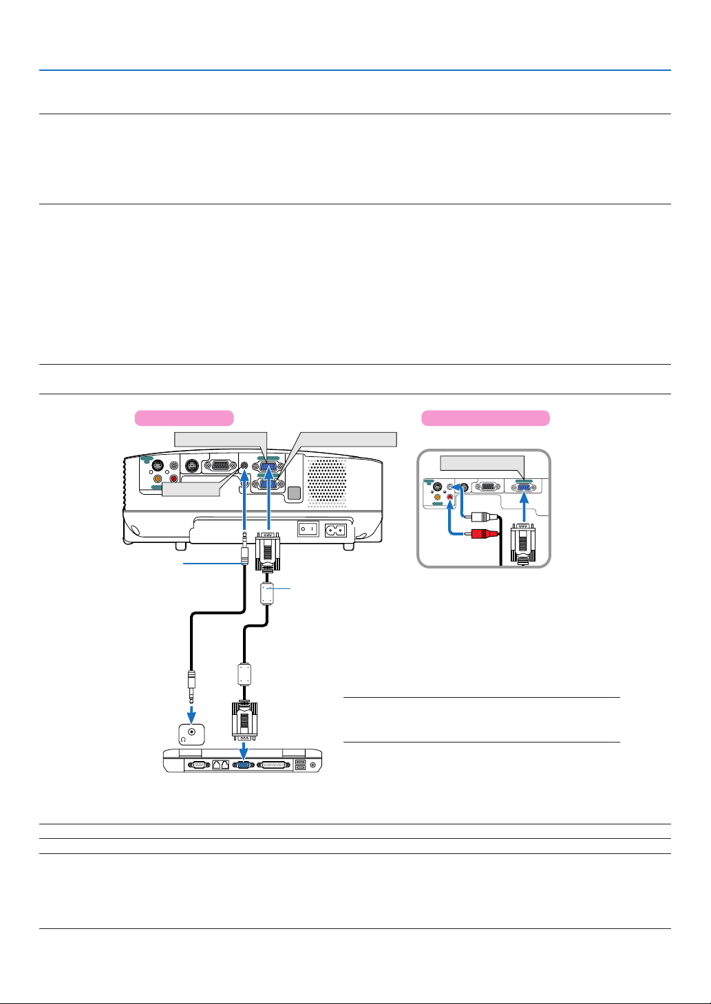
Connecting Your PC or Macintosh Computer
NOTE: • VT580/VT480: The COMPUTER 1 connector supports Plug & Play (DDC2).
• VT58/VT57/VT48: The COMPUTER connector supports Plug & Play (DDC2).
VT580/VT480
COMPUTER 1 IN
MONITOR OUT(COMP 1)
L
R
VIDEO IN
AUDIO IN
AUDIO IN
PC CONTROL
S-VIDEO
IN
Audio cable
(not supplied)
PHONE
IBM VGA or Compatibles (Notebook
type) or Macintosh (Notebook type)
AUDIO IN
AUDIO OUT
COMPUTER 1 IN
COMPUTER 2 IN
VT58/VT57/VT48
COMPUTER 2 IN
VGA signal cable (supplied)
To mini D-Sub 15-pin connector on the projector. It is
recommended that you use a commercially available
distribution amplifier if connecting a signal cable longer
than the supplied one.
NOTE: For older Macintosh, use a commercially available
pin adapter (not supplied) to connect to your Mac's
video port.
NOTE: The projector is not compatible with video decoded outputs of either the NEC ISS-6020 and ISS-6010 switchers.
NOTE: An image may not be displayed correctly when a Video or S-Video source is played back via a commercially available scan
converter.
This is because the projector will process a video signal as a computer signal at the default setting. In that case, do the following.
* When an image is displayed with the lower and upper black portion of the screen or a dark image is not displayed correctly:
Project an image to fill the screen and then press the AUTO ADJ button on the remote control or the projector cabinet.
13
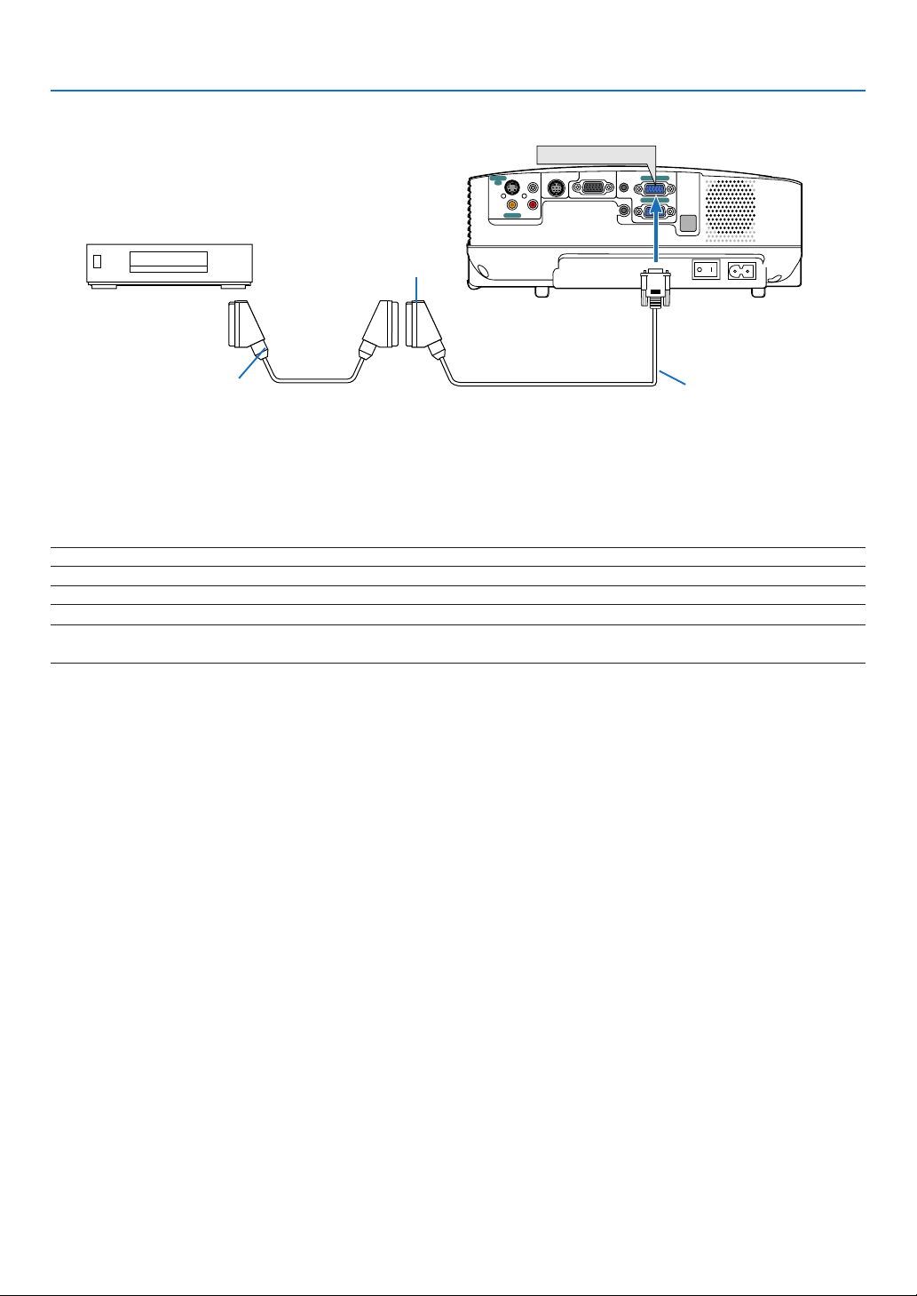
To connect SCART output (RGB)
Video equipment such as DVD player
Female
COMPUTER 1 IN
S-VIDEO
L
IN
R
VIDEO IN
AUDIO IN
2. Installation and Connections
Projector
PC CONTROL
MONITOR OUT(COMP 1)
AUDIO IN
AUDIO OUT
COMPUTER 1 IN
COMPUTER 2 IN
To COMPUTER 1 input
(COMPUTER input on VT58/
VT57/VT48)
Commercially available SCART cable
ADP-SC1
Before connections: An exclusive SCART adapter (ADP-SC1) and a commercially available SCART cable are required for this connection.
From the menu, select [Setup] → [Options] → [Signal Select] → [Computer 1 ([Computer] on VT58/VT57/VT48)] → [Scart].
SCART is a standard European audio-visual connector for TVs, VCRs and DVD players. It is also referred to as Euroconnector.
TIP: If a DVD or VCR source will not be displayed correctly, stop playback and restart it.
NOTE: Audio signal is not available for this connection.
TIP: The ADP-SC1 SCART adapter is obtainable from your NEC dealer in Europe. Contact your NEC dealer in Europe for more
information.
14
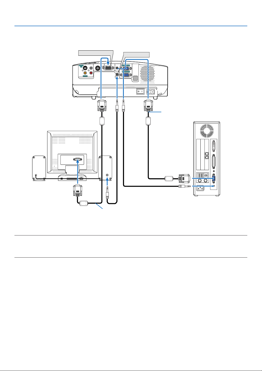
Connecting an External Monitor
2. Installation and Connections
MONITOR OUT
T
I
X
E
.
J
D
A
O
T
U
A
E
C
R
U
O
S
Y
B
D
N
A
T
S
/
N
O
VIDEO IN
AUDIO IN
PC CONTROL
L
R
AUDIO
S-VIDEO
IN
MONITOR OUT(COMP 1)
IN
AUDIO OUT
COMPUTER 1 IN
AUDIO IN
COMPUTER 2 IN
AUDIO OUT
VGA signal cable (supplied)
VGA signal cable (not supplied)
You can connect a separate, external monitor to your projector to simultaneously view on a monitor the RGB analog
image you're projecting.
NOTE:
• Daisy chain connection is not possible.
• The signal from the COMPUTER 2 IN connector cannot be output from the MONITOR OUT connector on VT580 and VT480.
• The VT58, VT57 and VT48 do not have the AUDIO OUT connector.
15
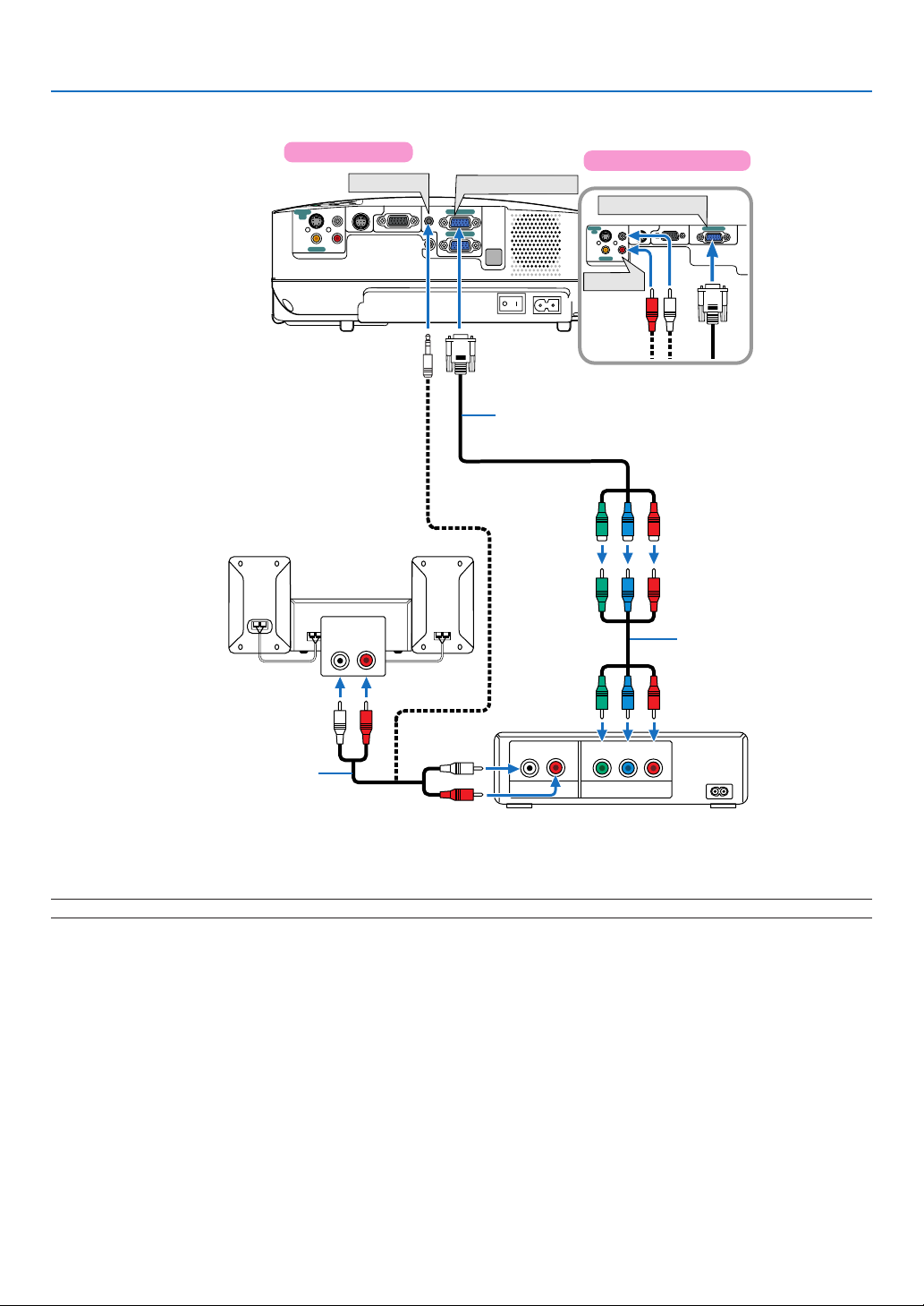
Connecting Your DVD Player with Component Output
2. Installation and Connections
VT580/VT480
Y
B
D
N
A
T
S
/
N
O
S-VIDEO
IN
VIDEO IN
Audio Equipment
AUDIO IN
T
I
X
E
.
J
D
A
O
T
U
A
E
C
R
U
O
S
PC CONTROL
L
R
AUDIO IN
AUDIO IN
LR
MONITOR OUT(COMP 1)
COMPUTER 1 IN
COMPUTER 1 IN
AUDIO IN
COMPUTER 2 IN
AUDIO OUT
VT58/VT57/VT48
COMPUTER IN
MONITOR OUT
PC CONTROL
S-VIDEO
L
IN
R
VIDEO IN
AUDIO IN
AUDIO IN
Optional 15-pin - to - RCA (female)
⳯
3 cable (ADP-CV1)
COMPUTER IN
Component video RCA⳯3
cable (not supplied)
DVD player
L R
Y Cb Cr
Audio cable (not supplied)
AUDIO OUT
Component
A component signal will be automatically displayed. If not, from the menu, select [Setup] → [Options] → [Signal
Select] → [Computer 1 ([Computer] on VT58/VT57/VT48)], and then place a check mark in the Component radio
button.
NOTE: Refer to your DVD player's owner's manual for more information about your DVD player's video output requirements.
16
 Loading...