


VT45
LCD Projector
User’s Manual
English
E–1
IMPORTANT INFORMATION
Precautions
Please read this manual carefully before using your
NEC VT45 Projector and keep the manual handy for
future reference.
Your serial number is located under the name plate
label on the right side of your VT45. Record it here:
CAUTION
To turn off main power, be sure to remove
the plug from power outlet.
The power outlet socket should be installed as near to the equipment as possible, and should be easily accessible.
CAUTION
TO PREVENT SHOCK, DO NOT OPEN
THE CABINET.
NO USER-SERVICEABLE PARTS INSIDE. REFER SERVICING TO QUALIFIED NEC SERVICE PERSONNEL.
This symbol warns the user that
uninsulated voltage within the unit may
be sufficient to cause electrical shock.
Therefore, it is dangerous to make any
kind of contact with any part inside of the
unit.
This symbol alerts the user that important information concerning the operation
and maintenance of this unit has been
provided. The information should be read
carefully to avoid problems.
RF Interference
WARNING
The Federal Communications Commission does
not allow any modifications or changes to the unit
EXCEPT those specified by NEC Technologies in
this manual. Failure to comply with this government regulation could void your right to operate
this equipment.
This equipment has been tested and found to comply with the limits for a Class B digital device, pursuant to Part 15 of the FCC Rules. These limits
are designed to provide reasonable protection
against harmful interference in a residential installation. This equipment generates, uses, and can
radiate radio frequency energy and, if not installed
and used in accordance with the instructions, may
cause harmful interference to radio communications. However, there is no guarantee that interference will not occur in a particular installation. If
this equipment does cause harmful interference
to radio or television reception, which can be determined by turning the equipment off and on, the
user is encouraged to try to correct the interference by one or more of the following measures:
• Reorient or relocate the receiving antenna.
• Increase the separation between the equipment
and receiver.
• Connect the equipment into an outlet on a circuit
different from that to which the receiver is connected.
• Consult the dealer or an experienced radio / TV
technician for help.
WARNING
TO PREVENT FIRE OR SHOCK, DO NOT EXPOSE
THIS UNIT TO RAIN OR MOISTURE.
DO NOT USE THIS UNIT’S GROUNDED PLUG WITH
AN EXTENSION CORD OR IN AN OUTLET UNLESS
ALL THREE PRONGS CAN BE FULLY INSERTED.
DO NOT OPEN THE CABINET. THERE ARE HIGHVOLTAGE COMPONENTS INSIDE. ALL SERVICING
MUST BE DONE BY QUALIFIED NEC SERVICE PERSONNEL.
DOC Compliance Notice
This Class B digital apparatus meets all requirements
of the Canadian Interference-Causing Equipment
Regulations.
3. GSGV Acoustic Noise Information Ordinance:
The sound pressure level is less than 70 dB (A) according to ISO 3744 or ISO 7779.
In UK, a BS approved power cable with moulded plug
has a Black (five Amps) fuse installed for use with
this equipment. If a power cable is not supplied with
this equipment please contact your supplier.
• IBM is a registered trademark of International Business Machines Corporation.
• Macintosh and PowerBook are registered trademarks of Apple
Computer, Inc.
• Other product and company names mentioned in this user's
manual may be the trademarks of their respective holders.
E–2
Important Safeguards
These safety instructions are to ensure the long life
of your projector and to prevent fire and shock. Please
read them carefully and heed all warnings.
Installation
1. For best results, use your projector in a darkened room.
2. Place the projector on a flat, level surface in a dry area
away from dust and moisture.
3. Do not place your projector in direct sunlight, near heaters or heat radiating appliances.
4. Exposure to direct sunlight, smoke or steam can harm
internal components.
5. Handle your projector carefully. Dropping or jarring can
damage internal components.
6. Do not place heavy objects on top of the projector.
7. If you wish to have the projector installed on the ceiling:
a. Do not attempt to install the projector yourself.
b. The projector must be installed by qualified techni-
cians in order to ensure proper operation and reduce
the risk of bodily injury.
c. In addition, the ceiling must be strong enough to sup-
port the projector and the installation must be in accordance with any local building codes.
d. Please consult your dealer for more information.
Power Supply
1. The projector is designed to operate on a power supply
of 100-120 or 200-240 V 50/60 Hz AC. Ensure that your
power supply fits this requirement before attempting to
use your projector.
2. Handle the power cable carefully and avoid excessive
bending. A damaged cord can cause electric shock or
fire.
3. If the projector is not to be used for an extended period
of time, disconnect the plug from the power outlet.
CAUTION
Do not turn off the main power or unplug the power cable
from the wall outlet under any one of the following circumstances. Doing so can cause damage to the projector:
• Immediately after the power cable is plugged into the wall
outlet (when the POWER indicator has not changed to a
steady orange glow).
• Immediately after the cooling fan stops working (The cooling fan continues to work for 60 seconds after the projector is turned off with the POWER button).
CAUTION
Avoid displaying stationary images for a prolonged period
of time.
Doing so can result in these images being temporarily sustained on the surface of the LCD panel.
If this should happen, continue to use your projector. The
static background from previous images will disappear.
Cleaning
1. Unplug the projector before cleaning.
2. Clean the cabinet periodically with a damp cloth. If
heavily soiled, use a mild detergent. Never use strong
detergents or solvents such as alcohol or thinner.
3. Use a blower or lens paper to clean the lens, and be
careful not to scratch or mar the lens.
E–3

Lamp Replacement
• To replace the lamp, follow all instructions provided on
page E-36.
• Be sure to replace the lamp when the message "The
lamp has reached the end of its usable life. Please replace the lamp." appears. If you continue to use the lamp
after the lamp has reached the end of its usable life, the
lamp bulb may shatter, and pieces of glass may be scattered in the lamp case. Do not touch them as the pieces
of glass may cause injury. If this happens, contact your
NEC dealer for lamp replacement.
• Allow a minimum of 60 seconds to elapse after turning
off the projector. Then disconnect the power cable and
allow 60 minutes to cool the projector before replacing
the lamp.
Fire and Shock Precautions
1. Ensure that there is sufficient ventilation and that vents
are unobstructed to prevent the build-up of heat inside
your projector. Allow at least 3 inches (10 cm) of space
between your projector and a wall.
2. Prevent foreign objects such as paper clips and bits of
paper from falling into your projector. Do not attempt to
retrieve any objects that might fall into your projector.
Do not insert any metal objects such as a wire or screwdriver into your projector. If something should fall into
your projector, disconnect it immediately and have the
object removed by a qualified NEC service personnel.
3. Do not place any liquids on top of your projector.
• Do not look into the lens while the projector is on. Serious damage to your eyes could result.
• Keep any items such as magnifying glass out of the
light path of the projector. The light being projected from
the lens is extensive, therefore any kind of abnormal
objects that can redirect light coming out of the lens,
can cause unpredictable outcome such as fire or injury
to the eyes.
• Do not cover the lens with the supplied lens cap or
equivalent while the projector is on. Doing so can lead
to melting of the cap and possibly burning your hands
due to the heat emitted from the light output.
E–4

TABLE OF CONTENTS
1. INTRODUCTION
Introduction to the VT45 Projector ......................... E-6
Getting Started ....................................................... E-6
What’s in the Box ................................................... E-7
Getting to Know Your VT45 Projector .................... E-8
Front / Side Features ......................................... E-8
Rear / Side Features ......................................... E-8
Bottom / Side Features ...................................... E-9
Top Features ................................................... E-10
Terminal Panel Features ................................. E-11
Remote Control Features ................................ E-12
Opeating Range .............................................. E-13
Remote Control Battery Installation ................. E-13
2. INSTALLATION
Setting Up Your Projector ..................................... E-14
Selecting a Location .............................................E-14
Using a Tabletop or Cart ....................................... E-14
Using the Lens Shift ............................................. E-14
Distance Chart ..................................................... E-15
Ceiling Installation ................................................ E-16
Reflecting the Image ............................................ E-16
Wiring Diagram .................................................... E-17
Connecting Your PC ........................................ E-18
Connecting Your Macintosh Computer ............ E-19
Connecting an External Monitor ...................... E-20
Connecting Your DVD Player .......................... E-21
Connecting Your VCR or Laser Disc Player .... E-22
3. OPERATION
General Controls .................................................. E-23
About Startup Screen ...........................................E-24
Enlarging and Moving a Picture ........................... E-25
Geometrical correction ......................................... E-25
Using the Menus .................................................. E-26
Menu Tree ............................................................ E-27
Menu Elements .................................................... E-28
Menu Descriptions & Functions ........................... E-29
Source Select .......................................................E-29
RGB/Video/S-Video
Picture .................................................................. E-29
Brightness/Contrast/Color/Hue/Sharpness
Volume ................................................................. E-29
Image Options ......................................................E-29
Keystone ......................................................... E-29
Lamp Mode ..................................................... E-30
Advanced Options ........................................... E-30
Aspect Ratio .................................................... E-30
Position/Clock .................................................. E-31
Resolution ....................................................... E-31
Video Filter ...................................................... E-31
Factory Default ................................................ E-31
Color Management ............................................... E-32
Gamma Correction .......................................... E-32
Color Correction .............................................. E-32
User Adjust ...................................................... E-32
White Balance ................................................. E-32
Projector Options ................................................. E-32
Menu ............................................................... E-32
Menu Mode ................................................. E-32
Basic/Advanced ..........................................E-32
Language .................................................... E-32
Source Display ........................................... E-32
No Input Display ......................................... E-33
Volume Bar (Direct Button) ......................... E-33
Keystone Bar (Option) ................................ E-33
Filter Clean Message .................................. E-33
Menu Display Time .....................................E-33
Setup ............................................................... E-33
Orientation .................................................. E-33
Cinema Position ......................................... E-33
Background ................................................ E-33
Signal Select ............................................... E-33
Auto Adjust ................................................. E-34
Auto Start .................................................... E-34
Power Management ................................... E-34
Power Off Confirmation .............................. E-34
Keystone Save ........................................... E-34
Fan High Speed Mode ................................ E-34
Default Source Select .................................E-34
Communication Speed ............................... E-34
Control Panel Key Lock .............................. E-34
Clear Lamp Hour Meter .............................. E-35
Clear Filter Usage ....................................... E-35
Information ........................................................... E-35
4. MAINTENANCE
Replacing the Lamp ............................................. E-36
Cleaning or Replacing the Filters ......................... E-37
5. TROUBLESHOOTING
Power / Status Light Messages ............................ E-38
Common Problems & Solutions ........................... E-38
6. SPECIFICATIONS
Optical/Electrical/Mechanical ............................... E-39
Cabinet Dimensions ............................................. E-40
D-Sub Pin Assignments ....................................... E-41
Timing Chart ......................................................... E-42
PC Control Codes ................................................ E-43
Cable Connection ................................................. E-43
E–5

1. INTRODUCTION
Introduction to the VT45 Projector
This section introduces you to your new VT45 (SVGA) Projector and describes the features and controls.
Congratulations on Your Purchase of The VT45 Projector
The VT45 is one of the very best projectors available today. The
VT45 enables you to project precise images up to 300 inches
across (measured diagonally) from your PC or Macintosh computer (desktop or notebook), VCR, DVD player, document camera, or even a laser disc player.
You can use the projector on a tabletop or cart, you can use the
projector to project images from behind the screen, and the projector can be permanently mounted on a ceiling*
control can be used wirelessly.
Features you’ll enjoy:
• Simple set up and operation.
• Eco Mode, two selectable options (120 watt for Eco 1 and
110 watt for Eco 2) that allow users to reduce the projector’s
light output, resulting in a doubling (Eco 2) of usable lamp
life and decreased lamp replacement costs throughout the
projector’s life.
• A high-performance 130 watt NSH lamp.
• Manual horizontal (max 1/3 of widith) and vertical (max 1/
2 of height) lens shift provides simple imaging positioning.
• The lamp life can be extended up to 2000 hours by using
the Eco 2 mode.
• The supplied wireless remote control that operates the projector from the front side or rear.
• Manual zoom control enables you to adjust the image between 25 (0.63 m) and 300 inches (7.6 m) (measured diagonally).
• Keystone correction allows you to correct trapezoidal distortion so that the image is square.
• Color Management feature includes Gamma Correction,
White Balance, and Color Correction that provides natural
and true color reproduction.
• You can choose between video modes depending on your
source: “normal” for a typical picture, “natural” for true
color reproduction.
• An image can be projected from in front or behind a screen,
and the projector can even be installed on the ceiling.
• NEC Technologies’ exclusive Advanced AccuBlend intelligent pixel blending technology - an extremely accurate
image compression technology - offers a crisp image with
SXGA (1280 1024) resolution*
• Supports most IBM VGA, SVGA, XGA*
Macintosh, component signal (YCbCr / YPbPr) or any other
RGB signals within a horizontal frequency range of 15 to
80 kHz and a vertical frequency range of 50 to 100 Hz. This
includes NTSC, PAL, PAL60, SECAM and NTSC4.43 standard video signals.
NOTE: Composite video standards are as follows:
NTSC: U.S. TV standard for video in U.S. and Canada.
PAL: TV standard used in Western Europe.
PAL60: TV standard used for NTSC playback on PAL TVs.
SECAM: TV standard used in France and Eastern Europe.
NTSC4.43: TV standard used in Middle East countries.
2
.
1
. The remote
2
, SXGA*2,
• The supplied remote control can be used without a cable.
• You can control the projector with a PC using the PC Con-
trol port.
• The contemporary cabinet design is light, compact, easy to
carry, and complements any office, boardroom or auditorium.
*1 Do not attempt to mount the projector on a ceiling your-
self. The projector must be installed by qualified technicians in order to ensure proper operation and reduce the risk
of bodily injury. In addition, the ceiling must be strong
enough to support the projector and the installation must be
in accordance with any local building codes. Please consult
your dealer for more information.
*2 An XGA image (1024768) and SXGA image
(12801024) are converted into an 800600 crisp image
with NEC technology’s Advanced AccuBlend.
Getting Started
The fastest way to get started is to take your time and do everything right the first time. Take a few minutes now to review the
user’s manual. This may save you time later on. At the beginning of each section of the manual you’ll find an overview. If the
section doesn’t apply, you can skip it.
E–6
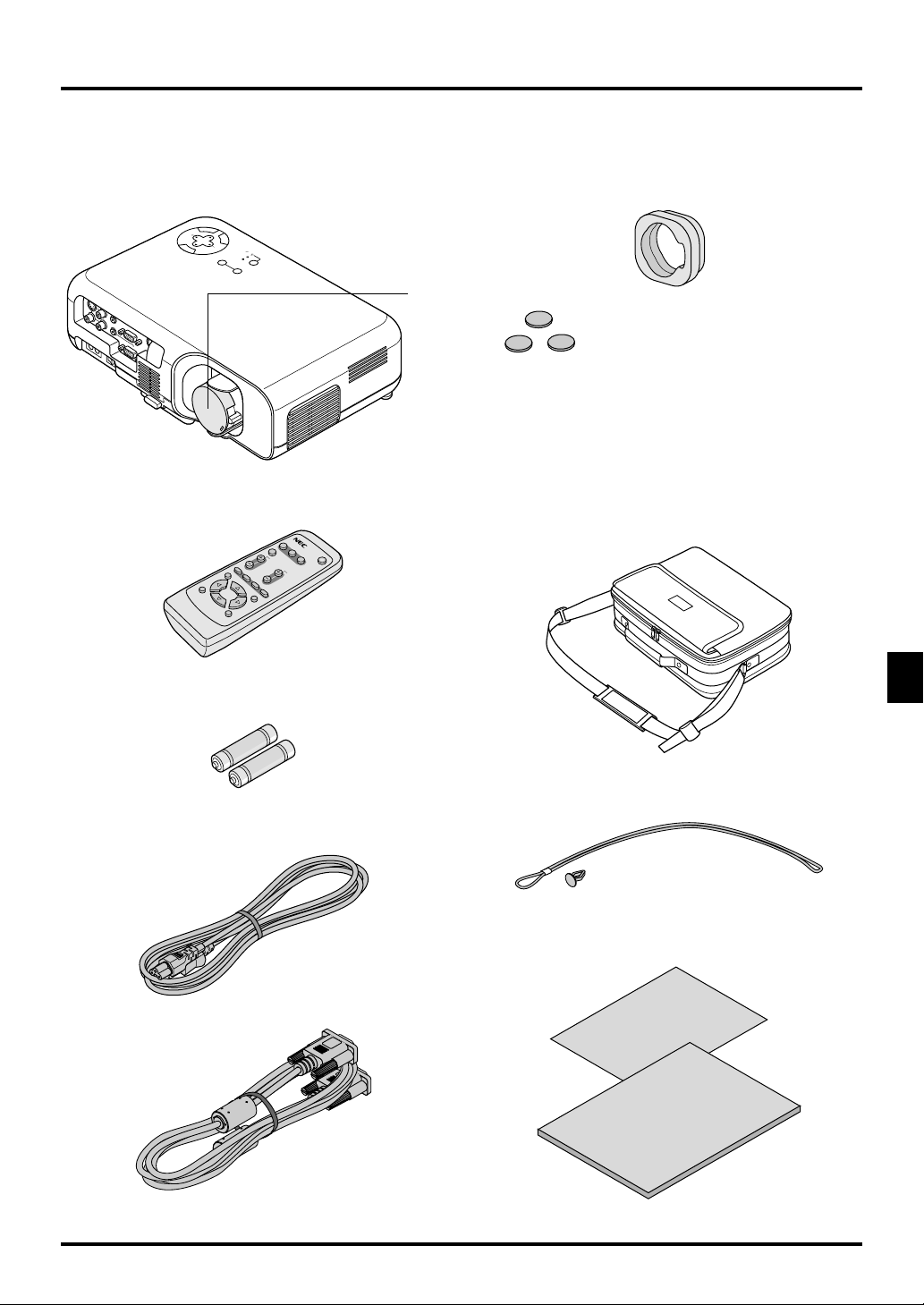
What's in the Box?
Make sure your box contains everything listed. If any pieces are missing, contact your dealer.
Please save the original box and packing materials if you ever need to ship your VT45 Projector.
L
E
C
N
A
C
R
E
T
C
T
N
LE
E
E
S
U
S-VIDEO
I
N
V
I
D
E
O
L
/
M
O
N
I
O
N
O
U
T
R
R
GB OU
I
N
T
I
C
N
P
O
C
N
T
R
O
L
R
GB
IN
BY
N
ND
E
M
AUTO ADJUST
STA
ER
ON
POW
STATUS
SOURCE
Lens cap
Non-slip rubber pad
They can be applied to the projector cabinet when the projector is positioned upside down in a place such as a tall
cabinet.
Projector
Stick the three small non-slip rubber pads on the projector
top cabinet to avoid accidental button operation when the
projector is turned upside down.
RGB
V
ID
E
O
S
-
AUTO ADJ.
V
ID
E
MAGNIFY
O
PICTU
RE
MENU
FREEZE MUTE
ENTER
RD-372E
HELP
CANCEL
POWER
VOLUME
ASPECT
Protective lens pad
Remote control
Batteries
Power cable
String and rivet
Quick
Connect
Guide
User's
Manual
Soft carrying case
Signal cable
E–7
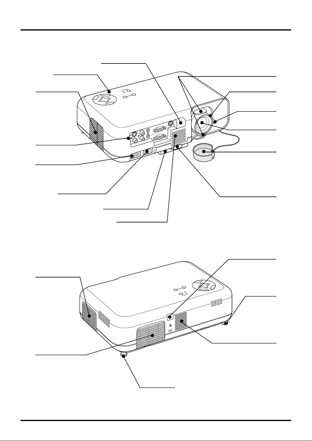
Getting to Know Your VT45 Projector
Front / Side Features
Controls
Ventilation (outlet)
Terminal Panel
AC Input
Connect the supplied power
cable’s three-pin plug here.
Main Power Switch
Remote Sensor
C
A
N
C
E
L
T
SE
LECT
M
E
N
U
STAND BY
WE
R
S
E
R
T
N
E
Adjustable Tilt Foot
Ventilation (inlet)
Lens Shift Lever
ON
P
O
S
S
O
TAT
U
RC
U
E
A
UT
O
A
D
JUS
Focus Ring
Zoom Lever
C
P
CONTROL
T
U
O
B
G
R
UT
O
O
N
O
/M
L
IN
IN
B
G
R
IN
IN
IN
IN
R
AC IN
Lens
Lens Cap
Adjustable Tilt Foot Button
Rear / Side Features
Air-Filter (inlet)
Air-Filter (inlet)
Rear Foot
Remote Sensor
U
N
E
M
T
C
E
L
E
L
S
E
C
N
A
C
AUTO ADJUST
SOURCE
E
N
T
R
STATUS
E
POWER
STAND BY
ON
Rear Foot
Built-in Monaural Speaker (2W)
E–8
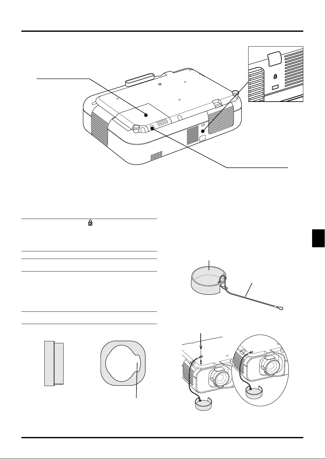
Bottom / Side Features
Lamp Cover
Slot for Kensington
MicroSaver
Security System
Lamp Cover Screw
NOTE: Built-in Security Slot ( )
This security slot supports the MicroSaver® Security System.
MicroSaver® is a registered trademark of Kensington Microware
Inc.The logo is trademarked and owned by Kensington Microware
Inc.
NOTE:When moving the projector or when it is not in use, cover
the lens with the lens cap.
Using the protective lens pad
To protect the Lens Shift mechanism, a hard polyurethane
protective lens pad is attached to the lens.
Before using the projector, remove the protective lens pad. After
use, reattach the protective lens pad.
NOTE: Before reattaching the protective lens pad, be sure to
use the shift lever to move the lens to the center position.
Side view Front view
Attaching the lens cap to the bottom with the supplied string and rivet
1. Thread the string through the hole on the lens cap and then
tie a knot in the string.
Lens Cap
String
2. Use the rivet to attach the string to the bottom.
Rivet
Notch for zoom lever
E–9
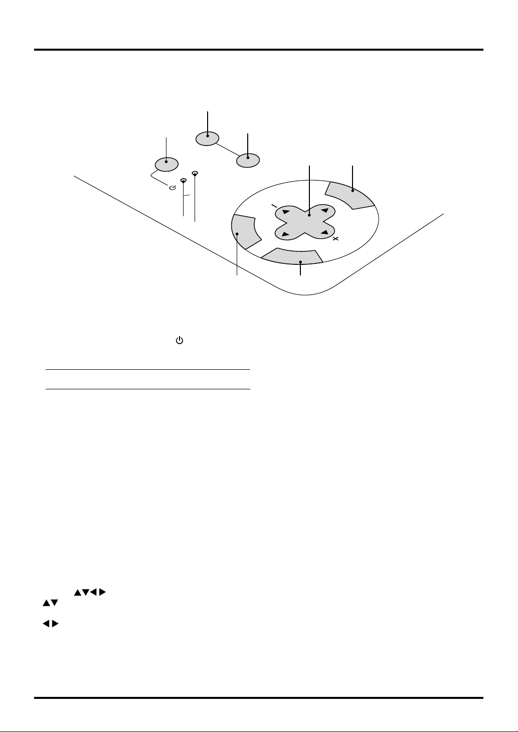
Top Features
9
1
SOURCE
AUTO ADJUST
STATUS
POWER
ON
STAND BY
3
2
1. Power Button (ON / STAND BY) ( )
Use this button to turn the power on and off when the power is
supplied and the projector is in standby mode.
NOTE: To turn off the projector, press and hold this button
for minimum of two seconds.
2. Status Indicator
When this is lit red continually, it’s warning you that the
projection lamp has exceeded 1000 hours (up to 2000 hours in
Eco 2 mode and 1500 hours in Eco 1 mode) of service. After
this light appears, it is advisable to replace the projection lamp
as soon as possible. (See page E-36). In addition the message
“The lamp has reached the end of its usable life. Please replace the lamp.” appears each time the projector is turned on
until the lamp is replaced.
If this light blinks red rapidly, it indicates that the lamp cover
or filter cover is not attached properly or the projector is overheated. See the Power / Status Light Messages on page E-38
for more details.
3. Power Indicator
When this indicator is green, the projector is on; when the
indicator is orange, it is in standby mode.
8
C
A
SELECT
N
C
E
N
T
E
R
6 5
5. Cancel Button
Press this button to exit the menu. While you are in the adjustment or setting menu, pressing this button will return to the
previous menu.
6. Enter Button
Executes your menu selection and activates items selected from
the menu.
7. Menu Button
Displays the menu.
8. Auto Adjust Button
Use this button to adjust Position-H/V and Pixel Clock/Phase
for an optimal picture. Some signals may not be displayed
correctly or take time to switch between sources.
9. Source Button
Use this button to select a video source such as a PC, VCR or
DVD player.
Each time this button is pressed, the input source will change
as follows:
→ RGB → Video → S-Video → RGB ...
If no input signal is present, the input will be skipped.
74
M
E
N
U
L
E
4. Select (
: Use these buttons to select the menu of the item you
: Use these buttons to change the level of a selected
When an image is magnified, these buttons can be used to
move the image on screen.
) / (+) (–) Buttons
wish to adjust.
menu item.
E–10
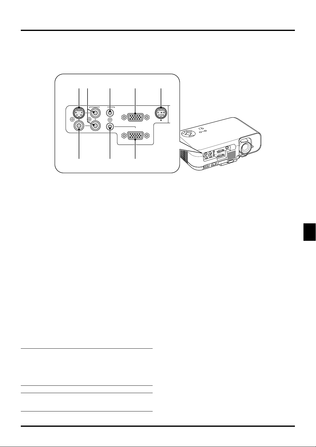
Terminal Panel Features
4 5 2 87
S-VIDEO
VIDEO
AUDIO
IN
IN
6
L/MONO
IN
IN
R
OUT
IN
3
RGB OUT
RGB IN
1
CONTROL
1. RGB Input Connector(Mini D-Sub 15 pin)
Connect your PC or other RGB equipment. Use the supplied
signal cable to connect to a PC.
2. RGB Monitor Output Connector (Mini D-Sub 15 pin)
You can use this connector to loop your computer image to an
external monitor from the RGB input source.
3. Audio Input (Mini Jack)
This is where you connect audio output from your computer.
4. Audio Input (RCA)
This is where you connect audio output from a VCR, DVD
player, or laser disc player.
5.Audio Output (Mini Jack)
Connect audio equipment to this jack. Note that this cannot be
used as a headphone jack.
(When audio equipment is connected, the projector speaker is
disabled.)
When a cable mini-plug is inserted into this jack, both the
right and left audio signals are not mixed, but separate.
For example, when a cable mini-plug is inserted into the left
AUDIO IN jack only, only left sound is output.
PC
ON
S
TAND B
P
O
W
E
Y
R
S
S
O
T
U
A
R
T
C
U
E
S
A
U
E
R
T
T
N
O
E
A
D
J
U
S
C
T
A
N
C
E
S
L
ELE
C
T
M
E
N
U
PC
L
O
R
T
N
O
C
RGB OUT
T
U
O
O
N
O
M
/
L
N
I
N
I
B
G
R
N
I
N
I
N
I
R
N
I
N
IN
I
C
C
A
A
6. Video Input (RCA)
Connect a VCR, DVD player, laser disc player, or document
camera here to project video.
7. S-Video Input Port (Mini DIN 4 Pin)
Connect the S-Video input from an external source like a VCR.
8. PC Control Port (Mini DIN 8 Pin)
Use this port to connect your PC to control your projector.
This enables you to use your PC and serial communication
protocol to control the projector. If you are writing your own
program, typical PC control codes are on page E-43.
NOTE1: ON AUDIO IN/OUT
The audio input (mini jack) 3 is available for RGB source only.
The audio input (RCA) 4 is available for Video or S-Video source
only.
The audio output (mini jack) 5 operates when audio source 3 or
4 is selected.
NOTE2: During Stand by Condition
RGB signal will be sent to the connected external monitor. Audio
signal will not be sent to the audio output.
E–11
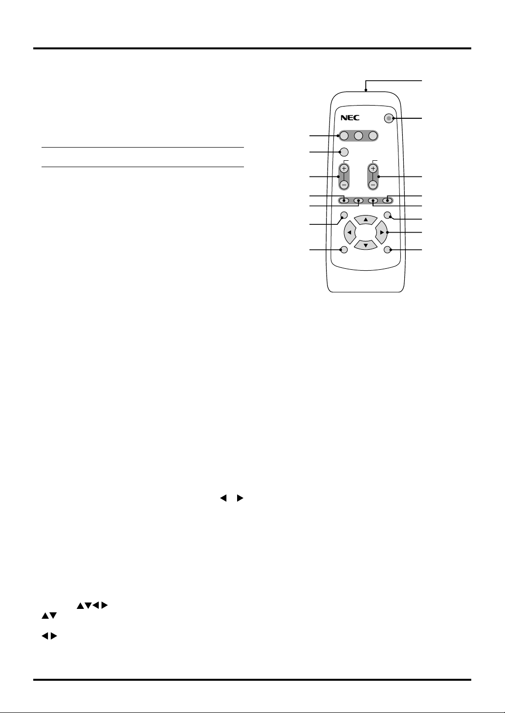
Remote Control Features
Remote Control
1. Infrared Transmitter
Direct the remote control toward the remote sensor on the projector cabinet.
2. Power Button
If power is applied, you can use this button to turn your projector on and off.
NOTE: To turn off the projector, press and hold the POWER
button for a minimum of two seconds.
3. Source Buttons
Press to select a video source.
4. Auto Adjust Button
Use this button to adjust Position-H/V and Pixel Clock/Phase
for an optimal picture. Some signals may not be displayed
correctly, or in some cases it may take some time for a source
to switch between sources.
5. Magnify Buttons
Use the (+) or (–) button to adjust the image size up to 400%.
6. Volume Buttons
Press (+) to increase the volume and (–) to decrease it.
7. Picture Button
Press this button to display the Picture adjustment window.
Each time this button is pressed, the current picture adjustment item will change as follows:
Brightness → Contrast → Color → Hue → Sharpness
Unavailable items will be skipped.
8. Freeze Button
This button will freeze a picture. Press again to resume motion.
9. Mute Button
This button turns off the image and sound for a short period of
time. Press again to restore the image and sound.
10. Aspect Button
Press this button to display the Aspect Ratio select window.
Each time this button is pressed, the current aspect ratio will
change as follows:
Normal → Zoom → Wide Zoom → Cinema → Normal → ...
You can also select the aspect ratio by using the Select
button. If no adjustments are performed within 3 seconds, the
Aspect Ratio select window will disappear. (See also page E-
30.)
11. Menu Button
Displays the menu.
12. Help Button
Provides information about the current signal and the status of
the projector.
13. Select (
) Buttons
: Use these buttons to select the menu of the item you
wish to adjust.
: Use these buttons to change the level of a selected
menu item.
or
1
RGB
VIDEO S-VIDEO POWER
2
3
4
5
7
8
11
AUTO ADJ.
VOLUME
MAGNIFY
PICTURE FREEZE MUTE ASPECT
MENU
HELP
6
10
9
12
13
14
ENTER
CANCEL
RD-372E
15
14. Enter Button
Executes your menu selection and activates items selected from
the menu.
15. Cancel Button
Press this button to exit the menu. While you are in the adjustment or setting menu, pressing this button will return to the
previous menu.
Remote Control Precautions
• Handle the remote control carefully.
• If the remote control gets wet, wipe it dry immediately.
• Avoid excessive heat and humidity.
• If you will not be using the remote control for a long time,
remove the batteries.
E–12

Operating Range
Remote Control Battery Installation
1. Push to open the battery cover.
30˚
7m
22 feet
30
˚
7m 7m
22 feet
30
˚
30˚
30˚
30˚
22 feet
7m
22 feet
30
˚
30
˚
2. Remove both old batteries and install new ones (AA). Ensure
that you have the batteries’ polarity (+/–) aligned correctly.
3. Put the battery cover back on.
Do not mix different types of batteries or new and old batteries.
E–13

2. INSTALLATION
This section describes how to set up your VT45 projector and
how to connect video and audio sources.
Setting up Your Projector
Your VT45 Projector is simple to set up and use. But before you
get started, you must first:
1. Determine the image size.
2. Set up a screen or select a non-glossy white wall onto which
you can project your image.
Ensure that the power cable and any other cables connecting to
video sources are disconnected before moving the projector.
When moving the projector or when it is not in use, cover the
lens with the lens cap.
Selecting a Location
The further your projector is from the screen or wall, the larger
the image. The minimum size the image can be is approximately
25" (0.64 m) measured diagonally when the projector is roughly
3 feet (1.0 m) from the wall or screen. The largest the image can
be is 300" (7.6 m) when the projector is about 39.3 feet (12.0 m)
from the wall or screen.
Using a Tabletop or Cart
1. Place your projector on a flat level surface at the optimal distance from the screen or wall so you realize the size image
you want. (Avoid having bright room lighting or sun light
directly on the screen or wall where you’ll be projecting the
image.)
2. Connect the power cable, remove the lens cap and turn the
projector on. (If no input signal is available, the projector
will display a background image.)
3. Ensure that the projector is square to the screen.
Top view
Screen
L
E
C
N
A
C
MENU
SELECT
R
E
T
N
E
STAND BY
ON
STATUS
POWER
AUTO ADJUST
SOURCE
5. To center the image vertically, lift the front edge of the projector and press the One-Touch Tilt button on the front side
of the projector to release the Front Adjustable foot.
Side view
Screen
(There is approximately 10 degrees of up and down adjustment for the front of the projector.)
Using the Lens Shift
1
C
P
CONTROL
B OUT
RG
OUT
O
N
O
/M
L
IN
RGB IN
IN
IN
R
1. Grip the lens shift lever on the top and bottom.
2. Hold the lever to move the lens vertically or horizontally.
NOTE: It may not be possible to obtain maximum shift range
due to the rounded off area near the edge of the lens. The amount
of lens shift adjustable range depends on the direction that the
lens is shifted. See diagram below.
Lens Shift Adjustable Range
Maximum shift image position
2
1
4. Move the projector left or right to center the image horizontally on the screen.
Width of
Projected
Image1/3
Height of Projected
Image1/2
Adjustable Range
E–14

Distance Chart
Throw Distance
C
Screen (inch)
Width
Screen Center
Lens Center/
B
Screen Bottom
B = Vertical distance between lens center and screen center
C = Throw distance
D = Vertical distance between lens center and bottom of screen for desktop
α = Throw angle
D
α
44.6 mm / 1.76”
Projector feet
Height
Screen Size (Diagonal)
Lens Offset 5.4mm
38
25"
Screen Size
(24")
61
40"
(36") (48")
91
122
60"
80"
152
(60")
Diagonal Width Height
inch mm inch mm inch mm inch mm inch mm - inch mm inch mm degree - degree
25 635 20 508 15 381 8 191 36 910 - 39 1000 0 0 11.8 - 10.8
30 762 24 610 18 457 9 229 43 1100 - 48 1210 0 0 11.7 - 10.7
40 1016 32 813 24 610 12 305 58 1470 - 64 1620 0 0 11.7 - 10.7
60 1524 48 1219 36 914 18 457 87 2220 - 96 2450 0 0 11.6 - 10.6
67 1702 54 1361 40 1021 20 511 98 2490 - 108 2740 0 0 11.6 - 10.6
72 1829 58 1463 43 1097 22 549 105 2670 - 116 2940 0 0 11.6 - 10.6
80 2032 64 1626 48 1219 24 610 117 2970 - 129 3270 0 0 11.6 - 10.6
84 2134 67 1707 50 1280 25 640 123 3120 - 135 3440 0 0 11.6 - 10.5
90 2286 72 1829 54 1372 27 686 132 3350 - 145 3690 0 0 11.6 - 10.5
100 2540 80 2032 60 1524 30 762 147 3730 - 161 4100 0 0 11.5 - 10.5
120 3048 96 2438 72 1829 36 914 176 4480 - 194 4930 0 0 11.5 - 10.5
150 3810 120 3048 90 2286 45 1143 220 5600 - 243 6170 0 0 11.5 - 10.5
180 4572 144 3658 108 2743 54 1372 265 6730 - 292 7410 0 0 11.5 - 10.5
200 5080 160 4064 120 3048 60 1524 294 7480 - 324 8240 0 0 11.5 - 10.5
210 5334 168 4267 126 3200 63 1600 309 7860 - 341 8650 0 0 11.5 - 10.5
240 6096 192 4877 144 3658 72 1829 354 8980 - 389 9890 0 0 11.5 - 10.5
261 6629 209 5304 157 3978 78 1989 385 9770 - 424 10760 0 0 11.5 - 10.5
270 6858 216 5486 162 4115 81 2057 398 10110 - 438 11130 0 0 11.5 - 10.5
300 7620 240 6096 180 4572 90 2286 443 11240 - 487 12370 0 0 11.5 - 10.5
B = Vertical distance between lens center and screen center
C = Throw distance
D = Vertical distance between lens center and bottom of screen for desktop
α = Throw angle
(15")
183
(72")
B
wide tele
229
(90")
100"
120"
150"
C
305
(120")
D
α
wide tele
NOTE: Distances may vary +/–5%.
Unit : cm (inch)
381
(150")
457
(180")
Screen
200"
In this example the projector is upside down with the lens shift maximum position.
When the projector is positioned upside down in a place such as a tall cabinet or
shelf, follow the below.
• Place the projector on a flat and level surface.
• To avoid accidental button operation, stick the supplied three non-slip rubber
pads on three locations on the projector top cabinet as shown in the drawing.
They are a peel-and –sticker pad. Before use, peel the paper off the back of the
rubber pad.
E–15
250"
Non-slip rubber pads
ON
STAND BY
P
O
W
E
R
S
S
O
T
U
A
R
T
C
U
EA
S
U
E
R
T
T
N
O
E
A
D
J
U
S
C
T
A
N
C
E
S
L
E
LE
C
T
M
E
N
U
RGB OUT
T
U
O
O
N
O
M
/
L
N
I
B
G
R
N
I
N
I
N
I
R
IN
N
N
I
I
C
C
A
A
300"
PC
L
O
R
T
N
O
C
N
I

Ceiling Installation
Screen Bottom/
Lens Center
Screen Center
D
B
44.6 mm / 1.76”
α
Throw Distance
C
Projector feet
B = Vertical distance between lens center and screen center
C = Throw distance
D = Vertical distance between lens center and top of screen
α = Throw angle
Lens Offset 5.4mm
Diagonal Width Height
inch mm inch mm inch mm inch mm inch mm - inch mm inch mm degree - degree
25 635 20 508 15 381 8 191 36 910 - 39 1000 0 0 11.8 - 10.8
30 762 24 610 18 457 9 229 43 1100 - 48 1210 0 0 11.7 - 10.7
40 1016 32 813 24 610 12 305 58 1470 - 64 1620 0 0 11.7 - 10.7
60 1524 48 1219 36 914 18 457 87 2220 - 96 2450 0 0 11.6 - 10.6
67 1702 54 1361 40 1021 20 511 98 2490 - 108 2740 0 0 11.6 - 10.6
72 1829 58 1463 43 1097 22 549 105 2670 - 116 2940 0 0 11.6 - 10.6
80 2032 64 1626 48 1219 24 610 117 2970 - 129 3270 0 0 11.6 - 10.6
84 2134 67 1707 50 1280 25 640 123 3120 - 135 3440 0 0 11.6 - 10.5
90 2286 72 1829 54 1372 27 686 132 3350 - 145 3690 0 0 11.6 - 10.5
100 2540 80 2032 60 1524 30 762 147 3730 - 161 4100 0 0 11.5 - 10.5
120 3048 96 2438 72 1829 36 914 176 4480 - 194 4930 0 0 11.5 - 10.5
150 3810 120 3048 90 2286 45 1143 220 5600 - 243 6170 0 0 11.5 - 10.5
180 4572 144 3658 108 2743 54 1372 265 6730 - 292 7410 0 0 11.5 - 10.5
200 5080 160 4064 120 3048 60 1524 294 7480 - 324 8240 0 0 11.5 - 10.5
210 5334 168 4267 126 3200 63 1600 309 7860 - 341 8650 0 0 11.5 - 10.5
240 6096 192 4877 144 3658 72 1829 354 8980 - 389 9890 0 0 11.5 - 10.5
261 6629 209 5304 157 3978 78 1989 385 9770 - 424 10760 0 0 11.5 - 10.5
270 6858 216 5486 162 4115 81 2057 398 10110 - 438 11130 0 0 11.5 - 10.5
300 7620 240 6096 180 4572 90 2286 443 11240 - 487 12370 0 0 11.5 - 10.5
B = Vertical distance between lens center and screen center
C = Throw distance
D = Vertical distance between lens center and top of screen
α = Throw angle
Screen Size
B
wide tele
C
D
α
wide tele
WARNING
• Installing your projector on the ceiling must be done by a
qualified technician. Contact your NEC dealer for more
information.
* Do not attempt to install the projector yourself.
• Only use your projector on a solid, level surface. If the
projector falls to the ground, you can be injured and the
projector severely damaged.
• Do not use the projector where temperatures vary greatly.
The projector must be used at temperatures between 32˚F
(0˚C) and 95˚F (35˚C).
• Do not expose the projector to moisture, dust, or smoke.
This will harm the screen image.
• Ensure that you have adequate ventilation around your
projector so heat can dissipate. Do not cover the vents on
the side or the front of the projector.
If your projector is mounted on the ceiling and your image is
upside down, use the “Menu” and “Select” buttons on your projector cabinet or ▲▼ buttons on your remote control to correct
the orientation. (See page E-33.)
Reflecting the Image
Using a mirror to reflect your projector’s image enables you to
enjoy a much larger image. Contact your NEC dealer if you need
a mirror. If you’re using a mirror and your image is inverted, use
the “Menu” and “Select” buttons on your projector cabinet or
▲▼ buttons on your remote control to correct the orientation.
(See page E-33.)
E–16

Wiring Diagram
Speaker System
Macintosh or Compatibles
(Desktop type or notebook type)
S-VIDEO
IN
VIDEO
IN
Document Camera
VCR, DVD Player or LaserDisc Player
To video, S-video, and audio
inputs on the projector.
AUDIO
L/MONO
IN
IN
R
PC
CONTROL
RGB OUT
OUT
IN
RGB IN
IBM VGA or Compatibles
(Desktop type or notebook type)
Signal cable (supplied)
To mini D-Sub 15-pin connector on
the projector. It is recommended
that you use a commercially
available distribution amplifier if
connecting a signal cable longer
than the supplied cable.
DVD Player (with component output)
Monitor
Optional Component V cable
NOTE: When using with a notebook PC, be sure to connect between the projector and the notebook PC before turning on the power to the notebook PC. In most cases signal cannot be output
from RGB output unless the notebook PC is turned on after connecting with the projector.
NOTE:
* If the screen goes blank while using your remote control, it may be the result of the computer’s
screen-saver or power management software.
* If you accidentally hit the POWER button on the remote control, wait 60 seconds and then
press the POWER button again to resume.
NOTE: If using video, S-video, or audio cables, the cables should be 3 m (9.8 feet) or shorter.
E–17

Connecting Your PC
IBM VGA or Compatibles
(Notebook type)
IBM VGA or Compatibles
(Desktop type)
Audio cable
(not supplied)
Signal cable (supplied)
To mini D-Sub 15-pin connector on the projector. It is
recommended that you use a commercially available distribution amplifier if connecting a signal cable longer than
the supplied one.
L
E
C
N
A
C
R
E
T
N
E
SELECT
Y
B
U
D
N
N
E
A
T
M
S
R
N
E
O
W
S
O
U
P
T
T
A
S
T
U
S
J
D
A
O
T
U
A
E
C
R
U
O
S
S
-VID
EO
IN
A
UD
VID
EO
IO
L
IN
/M
O
IN
N
O
O
AUDIO IN
U
T
R
RGB OUT
IN
IN
RGB IN
RGB IN
CONTROL
PC
Connecting your PC to your VT45 projector will enable you to project your computer’s screen image for an impressive presentation.
To connect to a PC, simply:
1. Turn off the power to your projector and computer.
2. Use the supplied signal cable to connect your PC to the projector.
3. Turn on the projector and the computer.
4. If the projector goes blank after a period of inactivity, it may be caused by a screen saver installed on the computer you’ve
connected to the projector.
E–18

Connecting Your Macintosh Computer
Macintosh (Notebook type)
Audio cable
(not supplied)
Signal cable
(supplied)
S-VIDE
L
E
C
N
A
C
R
E
T
T
N
LEC
E
SE
Y
B
U
D
N
N
E
A
T
M
S
R
N
E
O
W
S
O
U
P
T
T
A
S
T
U
S
J
D
A
O
T
U
A
E
C
R
U
O
S
O
IN
AU
V
ID
EO
DIO
L/M
IN
O
IN
N
O
O
AUDIO IN
U
T
R
IN
RGB OUT
PC
RGB IN
RGB IN
CONTROL
IN
Macintosh (Desktop type)
P
I
D
6
5
4
N
O
3
2
1
For older Macintosh,
use a commercially
available pin
adapter to connect to
your Mac's video port.
Pin adapter for Macintosh
(not supplied)
NOTE: The new Macintosh computer
such as G3 will have the 15 pin HD
connector. The VT45's "Plug and Play"
data will be downloaded to the
Macintosh. Therefore, the Mac adapter
will not be necessary.
To connect to a Macintosh, simply:
1. Turn off the power to your projector and your Macintosh
computer.
2. Use the supplied signal cable to connect your Macintosh
computer to the projector.
3. Turn on the projector and the Macintosh computer.
E–19

Connecting an External Monitor
External monitor
Audio cable
(not supplied)
S-VIDEO
IN
AUDIO IN
V
IDEO
IN
Signal cable
(supplied)
L
E
C
N
A
C
R
E
T
N
E
SELECT
Y
B
U
D
N
N
E
A
T
M
S
R
N
E
O
W
S
O
U
P
T
T
A
S
T
U
S
J
D
A
O
T
U
A
E
C
R
U
O
S
AUDIO
L/MONO
IN
OUT
RGB OUT
RGB OUT
R IN
P
CONT
C
RGB IN
RO
L
RGB IN
IN
AUDIO
You can connect a separate, external monitor to your VT45 to simultaneously view on a monitor the image you're projecting. To do so:
1. Turn off the power to your projector, monitor and computer.
2. Use a 15-pin cable to connect your monitor to the RGB Monitor Output (Mini D-Sub 15 pin) connector on your projector.
3. Turn on the projector, monitor and the computer.
NOTE: When the main power is turned off, RGB signal will not be sent to the external monitor.
E–20

Connecting Your DVD Player
DVD player
Audio Equipment
L
E
C
N
A
C
R
E
T
ECT
N
E
SEL
Y
B
U
D
N
N
E
A
T
M
Component video cable RCA3
(not supplied)
Cr
Cb
Y
L
R
White
Red
Green
Blue
Red
Green
Blue
Red
Blue
Red
S-VIDEO
VIDE
IN
AUD
O
IN
IO
L/M
O
IN
N
O
R IN
S
R
N
E
O
W
S
O
U
P
T
T
A
S
T
U
S
J
D
A
O
T
U
A
E
C
R
U
O
S
O
U
T
RGB OUT
PC
IN
CONTROL
RGB IN
RGB IN
Green
Optional 15-pin-to-RCA (female) 3 cable
(ADP-CV1)
Audio cable
(not supplied)
L
R
White
Red
You can connect your projector to a DVD player with component outputs or Video output. To do so, simply:
1. Turn off the power to your projector and DVD player.
2. If your DVD player has the component video (Y,Cb,Cr) output, use a commercially available component video cable (RCA3)
and the optional 15-pin-to-RCA (female) 3 cable to connect your DVD player to the RGB INPUT connector on the projector.
For a DVD player without component video (Y,Cb,Cr) outputs, use common RCA cables (not provided) to connect a composite
VIDEO output of the DVD player to the Video Input of the projector.
3. Turn on the projector and DVD player.
NOTE: Refer to your DVD player’s owner’s manual for more information about your DVD player’s video output requirements,
E–21

Connecting Your VCR or Laser Disc Player
VCR/ Laser disc player
L
R
White
Red
S-video cable
(not supplied)
Document camera
White
Red
S-VIDEO
VIDEO
AUDIO L IN
AUDIO R IN
S-VIDEO
VIDEO
L
E
C
N
A
C
R
E
T
N
E
SELECT
Y
B
U
D
N
N
E
A
T
M
S
R
N
E
O
W
S
O
U
P
T
T
A
S
T
U
S
J
D
A
O
T
U
A
E
C
R
U
O
S
IN
AUDIO
L/MONO
IN
IN
OUT
R IN
RGB OUT
PC
C
O
RGB IN
N
T
R
O
L
IN
Audio equipment
VIDEO
L
R
White
Red
Video cable (not supplied)
Audio cable
(not supplied)
Use common RCA cables (not provided) to connect your VCR, laser disc player or document camera to your projector.
To make these connections, simply:
1. Turn off the power to the projector and VCR, laser disc player or document camera.
2. Connect one end of your RCA cable to the video output connector on the back of your VCR or laser disc player, connect the other
end to the Video input on your projector. Use an audio cable (not supplied) to connect the audio from your VCR or laser disc player
to your audio equipment (if your VCR or laser disc player has this capability). Be careful to keep your right and left channel
connections correct for stereo sound.
3. Turn on the projector and the VCR or laser disc player.
NOTE: Refer to your VCR or laser disc player owner’s manual for more information about your equipment’s video output require-
ments.
NOTE: The VT45 is not compatible with video decoded outputs of ISS-6020 and ISS-6010.
NOTE: An image may not be displayed correctly when a Video or S-Video source is played back in fast-forward or fast-rewind via a
scan converter.
E–22

3.OPERATION
This section describes how to select a computer or video source,
how to adjust the picture, and how to customize the menu or projector settings.
General Controls
Before you turn on your projector, ensure that the computer or video
source is turned on and that your lens cap is removed.
1. Turn on the Projector
Plug the supplied power cable in the wall outlet and then press the
main power switch. The projector will go into its standby mode and
the power indicator will glow orange.
Only after you press the “POWER” button on the projector cabinet
or the remote control will the power indicator turn to green and the
projector become ready to use.
Indicator status when the projector is turned on:
Standby
STATUS
POWER
Steady orange light
Flashing green
light for one minute Steady green light
POWER
The STATUS indiator’ light depends on the lamp mode.
NOTE: To turn the projector on by pressing the main power switch,
use the menu and enable the “Auto Start” feature. (See page E-34.)
NOTE: Immediately after turning on the projector, screen flicker
may occur. This is not a fault. Wait for 3 to 5 minutes until the lamp
lighting is stabilized.
2. Select the Computer or Video Source
Press the Source button on the remote control or the projector cabinet to select “Video” (VCR, document camera, or laser disc player),
“S-Video” or “RGB” (computer or DVD with component output) to
display the image.
Or press the “Menu” button on the remote control or the cabinet and
use the menu to select your video source: “Video”, “S-Video” or
“RGB”.
3. Adjust the Lens Shift, the Image Size and the Focus
Use the Lens Shift lever to adjust the image position.
Use the Zoom lever to adjust the image size, then use the Focus ring
to obtain the best focus.
Use the “Magnify” button (+) or (-) on the remote control to make
the image larger up to 400%.
<
POWER>/
<
ON/STAND BY
POWER
>
4. Turning off the Projector
First press the “POWER” button on the projector cabinet or the remote control for a minimum of two seconds. The power indicator
will glow orange. After the projector turns off, the cooling fans keep
operating for 60 seconds.
Do not disconnect the power cable during this time. Then, press the
main power switch and unplug the power cable. The power indicator will go out.
Indicator status when the projector is turned off:
<
POWER>/
<
ON/STAND BY
Press
for a
minimum of
2 s
econds
Cooling fan running
STATUS
POWER
Flashing green light
Standby(cooling fan
has stopped running)
Steady orange light
>
STATUS
POWER
IMPORTANT:
• The projector should be unplugged if it will not to be used for an
extended period.
• To turn off the image and sound briefly (five minutes or less), use
the “Mute” button instead of turning the projector off and on.
• The projector will display a black, blue image or logo if no input
signal is present.
• Do not turn the projector off and then immediately back on. The
projector needs to cool for 60 seconds before it can be restarted.
CAUTION
Avoid displaying stationary images for a prolonged period
of time.
Doing so can result in these images being temporarily sustained on the surface of the LCD panel.
If this should happen, continue to use your projector. The
static background from previous images will disappear.
CAUTION
Do not turn off the main power or unplug the power cable
from the wall outlet under any one of the following circumstances. Doing so can cause damage to the projector:
• Immediately after the power cable is plugged into the wall
outlet (when the POWER indicator has not changed to a
steady orange glow).
• Immediately after the cooling fan stops working (The cooling fan continues to work for 60 seconds after the projector is turned off with the POWER button).
E–23

About Startup screen
(Menu Language Select screen)
When you first turn on the projector, you will get the Startup
screen.This screen gives you the opportunity to select one of the
seven menu languages: English, German, French, Itilan, Spanish, Swedish and Japanese.
To select a menu language, follow these steps:
1. Use the
or buttons to select one of the seven languages
for the menu.
Menu Language Select
Please select a menu language. English
Wählen Sie bitte die Menü Sprache aus. Deutsch
S'il vous plaît choisir la langue de menu. Français
Per favore di scegliere la lingua di menu. Italiano
Escoja por favor el idioma de menú. Español
Välj menyn språken. Svenska
Select "UP", "DOWN" & "ENTER"
2. Press the Enter button to execute the selection.
3. The Basic menu will be displayed in the language you have
selected.
Basic Menu
Source Select
Picture
Volume
Image Options
Projector Options
Information
To close the menu, press the Cancel button.
After this has been done, you can proceed to the advanced menu
operation.
If you want, you can select the menu language later. See “Lan-
guage” on page E-32.
E–24

Enlarging and Moving a Picture
You can enlarge the area you want up to 400 percent.
To do so:
Adjust the image size up to 400 percent.
MAGNIFY
MAGNIFY
While the picture is enlarged, you can move it using the “Select”
, , , or button.
Geometrical correction
If the image is distorted or not displayed correctly on the screen,
do the following.
Each of the feet height can be changed up to 1 mm or at angles
up to 1 degree.
Use keystone correction for proper adjustment. See page E-29.
Shifting Image Position
Use the lens shift lever to shift the lens so that the image position
can be adjusted on the screen.
Raise the projector height using the adjustable tilt-foot.
Rotate the projector to make the image square to the screen.
In this example, the lens is shifted horizontally to move the image to the right or left.
E–25

Using the Menus
1. Press the “Menu” button on the remote control or the projec-
tor cabinet to display the Menu.
In this example, the lens is shifted vertically to move the image
to the top or bottom.
Adjusting the Tilt Foot
1) Press and hold the Tilt button on the front of the projector.
2) Lift the front edge of the projector to the height you want, and
release the button to lock the Adjustable Tilt Foot.
ON
STAND BY
POWER
SOURCE
STATUS
AUTO ADJUST
E
R
T
N
E
C
A
N
C
E
S
L
ELE
C
T
M
E
N
U
C
P
L
O
R
T
N
O
C
T
U
O
B
G
R
T
U
O
O
N
O
M
/
L
IN
IN
B
G
R
IN
IN
IN
R
IN
A
2
IN
C
1
2. Press the
buttons on the remote control or the projector
cabinet to highlight the menu for the item you want to adjust
or set.
3. Press the
button or the “Enter” button on the remote con-
trol or the projector cabinet to select a submenu or item.
4. Adjust the level or turn the selected item on or off by using
“Select”
or buttons on the remote control or the projector cabinet. The on-screen slide bar will show you the amount
of increase or decrease.
5. The change is stored until you adjust it again.
CANCEL: Return to the previous screen.
6. Repeat steps 2-5 to adjust an additional item, or press “Can-
cel” on the remote control or the projector cabinet to quit the
menu display.
To fine-tune the image’s position vertically on the screen, rotate
the foot. Each of the rear feet height can be changed up to 1 mm /
0.04 inch
U
N
E
M
T
C
E
L
E
L
S
E
C
N
A
C
E
AUTO ADJUST
N
T
R
E
STATUS
SOURCE
POWER
STAND BY
ON
• If the projected image does not appear square to the screen
then use keystone correction for proper adjustment.
Adjust the size of the image using the Zoom lever on the
lens and obtain the best focus using the Focus ring.
E–26

MENU Tree
Basic/ Advanced Menu
Basic Menu
Source Select
Picture
Volume
Image Options
Projector Options
Information
Advanced Menu
Source Select
Picture
Volume
Image Options
Color Management
Projector Options
Information
Sub Menu
RGB
Video
S-Video
Picture
Brightness
Contrast
Color
Hue
Sharpness
Volume
Keystone
Lamp Mode
Advanced Options
Factory Default
Gamma Correction
Color Correction
White Balance
Menu
Setup
0
0
0
0
0
0
(Toutes)
Items
Normal/Eco 1/Eco 2
Aspect Ratio Normal/Zoom/Wide Zoom/Cinema
Position/Clock Horizontal/Vertical/Clock/Phase
Resolution Auto/Native
Video Filter Off/Less/More
All Data/Current Signal
Graphic/Linear/Black Enhance
Off/Mode1/Mode2/Mode3/sRGB/User1/User2
Color Correction(User Adjust) Color Tune/Yellow/
Magenta/Cyan/White
(On/Off)
Source Index
Input Terminal
Horizontal Frequency
Vertical Frequency
Sync Polarity
Signal Type
Video Type
Sync Type
Interlace
Remaining Lamp Time
Lamp Hour Meter
Projector Usage
Filter Usage
NOTE:
Some menu items are not available
depending on the input Source.
Brightness Red/Brightness Green/Brightness Blue/
Contrast Red/Contrast Green/Contrast Blue
Menu Mode Basic/Advanced
Language English/German/French/Italian/Spanish/
Swedish/Japanese
Source Display On/Off
No Input Display On/Off
Volume Bar On/Off
Keystone Bar* On/Off
Filter Clean Message
On/Off
Menu Display Time Manual/Auto 5 sec/Auto 15 sec/Auto 45 sec
* This setting is optional. you need the optional presentation
remote control (PR51KIT).
Orientation Desktop Front/Ceiling Rear/Desktop
Rear/Ceiling Front
Cinema Position Top/Center/Bottom
Background Blue/Black/Logo
Signal Select RGB Auto/RGB/Component
Signal Select Video/ Auto/NTSC3.58/NTSC4.43/PAL/
S-Video
PAL-M/PAL-N/PAL60/SECAM
Auto Adjust On/Off
Auto Start On/Off
Power Management On/Off
Power Off Confirmation On/Off
Keystone Save On/Off
Fan High Speed Mode On/Off
Default Source Select Last/Auto/Select
Communication Speed 4800/9600/19200
Control Panel Key Lock Lock/Unlock
Clear Lamp Hour Meter
Clear Filter Usage
E–27
Menu Elements
Title bar
Highlight
Menu Setup
Menu mode
Language
Source Display
No Input Display
Volume Bar
Keystone Bar
Filter Clean Message
Menu Display Time
Basic
English
On
On
On
On Off
On Off
Auto 45 Sec
Ta b
Setup
Page1 Page2 Page3 Page4
Orientation Desktop Front
Background
TopCinema Position
Logo
Solid triangle Slide ber
Color Correction(User Adjust)
0
0
0
0
Off
Off
Off
Color Tune
Yellow
Magenta
Cyan
White On Off
Radio button
○○○○○○○○○○○○○○○○○○○○○○○○○○○○○○○○○○○○○○○○○○○○○○○○○○○○○○○○
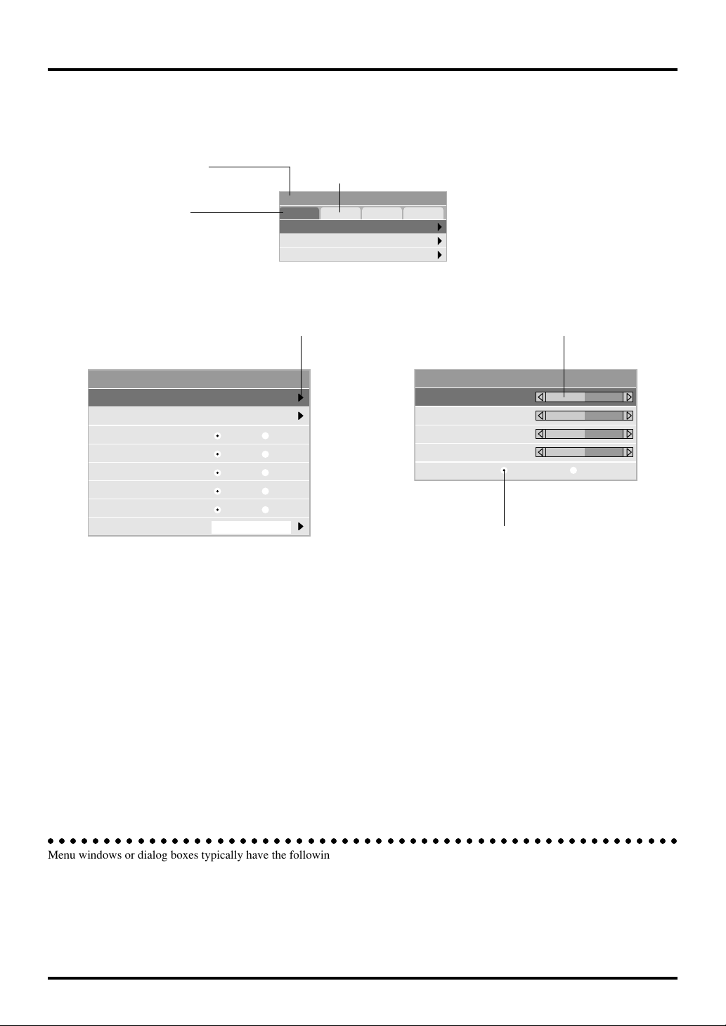
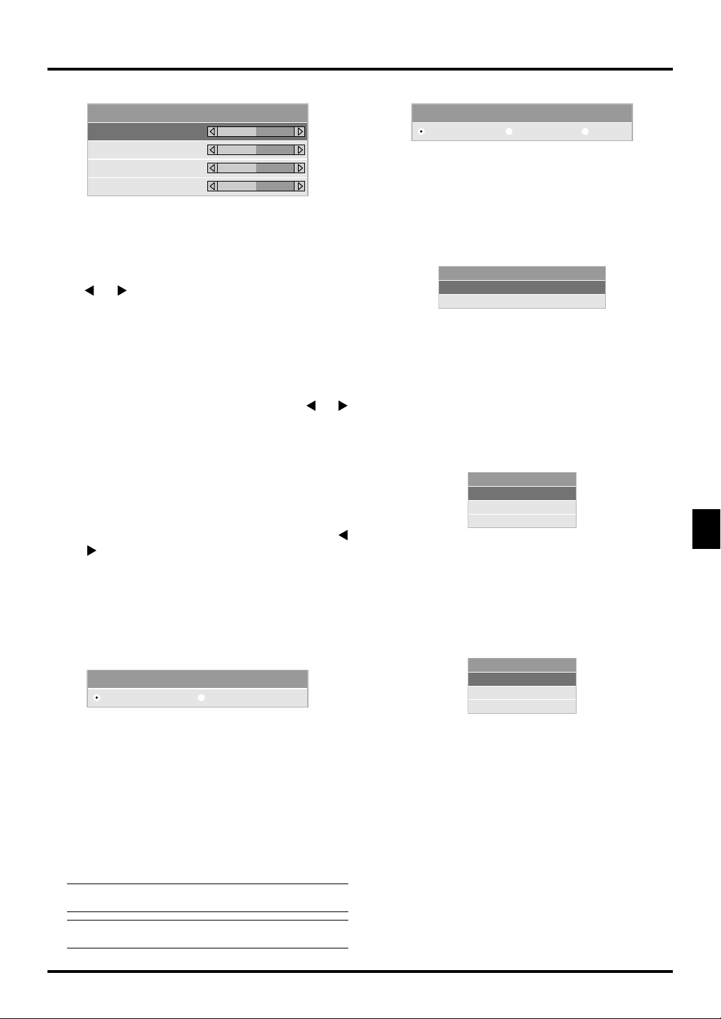
Menu windows or dialog boxes typically have the following elements:
Title bar: Indicates the menu title.
Highlight: Indicates the selected menu or item.
Solid triangle: Indicates further choices are available. A highlighted triangle indicates the item is active.
Tab: Indicates a group of features in a dialog box. Selecting on any tab brings its page to the front.
Radio button: Use this round button to select an option in a dialog box.
Slide bar: Indicates settings or the direction of adjustment.
E–28

Menu Descriptions & Functions
Keystone
Lamp Mode
Factory Default
Source Select
Enables you to select a video source such as a VCR, DVD player,
laser disc player, computer or document camera depending on
what is connected to your inputs. Press the “Select” button on
the projector cabinet or ▲▼ buttons on your remote control to
highlight the menu for the item you want to adjust.
RGB
Video
S-Video
Volume
Adjusts the sound level of the projector.
Volume
0
NOTE:You can display the volume bar without opening the menu.
See "Volume Bar (Direct Button)" on page E-33 for more details.
Image Options
<RGB>
Selects the computer connected to your RGB or component
signal.
NOTE: An optional component cable (Component V or ADPCV1 cable) is needed for a component signal.
<Video>
Selects what is connected to your Video input-VCR, laser
disc player, DVD player or document camera.
<S-Video>
Selects what is connected to your S-Video input-VCR, DVD
player, or laser disc player.
NOTE: A frame may freeze for a brief period of time when a
video is played back in fast-forward or fast-rewind with a
Video or S-Video source.
Picture
Picture
Brightness
Contrast
Color
Hue
Sharpness
0
0
0
0
0
Provides access to controls for your image. Use the “Select”
button on the projector cabinet or the remote control to highlight
the menu for the item you want to adjust.
<Brightness>
Adjusts the brightness level or the back raster intensity.
<Contrast>
Adjusts the intensity of the image according to the incoming
signal.
Basic Mode Advanced Mode
Keystone
Lamp Mode
Advanced Options
Factory Default
Provides optional controls such as Keystone Correction, Lamp
Mode and Factory Default. When you select Advanced Mode,
the following options are available: Aspect Ratio, Position/Clock,
Resolution, and Video Filter.
Keystone
Keystone
0
This feature corrects the keystone (trapezoidal) distortion to make
the top of the screen longer or shorter to be the same as the bottom.
Use the
(trapezoidal) distortion.
NOTE: The keystone angle can be corrected between 15 degrees
upward and 15 degrees downward at a 0 degree-projection angle.
Depending on the type of graphics being used, the picture may
get blurred or keystone correction may not be possible when excessive keystone correction is used. The idea is, the closer you
are to native resolution, the better image you will see.
or buttons on the slide bar to correct the keystone
Keystone distortion
Normal
<Color>
Increases or decreases the color saturation level (not valid
for RGB).
<Hue>
Varies the color level from +/- green to +/-blue. The red level
is used as reference. This adjustment is only valid for Video
and Component inputs (Not RGB).
<Sharpness>
Controls the detail of the image for Video (Not for RGB and
Component).
E–29

Lamp Mode
Aspect Ratio:
Lamp Mode
Normal Eco1 Eco2
This feature enables you to select three brightness modes of the
lamp: Normal and Eco modes. The lamp life can be extended up
to 2000 hours by using the Eco 2 mode.
Normal Mode: This is the default setting. This setting con-
sumes maximum current from the AC input and results in the most light output.
Eco 1 Mode: Select this mode to extend the lamp life by
up to 150%.
Eco 2 Mode: Select this mode to extend the lamp life by
up to 200%.
NOTE:
During the first one minute of operation the light output
from the projector will be brighter than during normal use. The
user will notice a slight drop off in brightness after the projector
has completed the start-up mode.
Advanced Options (Advanced mode)
Allows for adjustments of image position and stability.
Aspect Ratio
Position/Clock
Resolution
Video Filter
When you select Advanced Options in Advanced mode, the following options are available: Aspect Ratio, Position/Clock, Resolution, and Video Filter.
Aspect Ratio
Normal Zoom CinemaWide Zoom
Aspect Ratio allows you to select the best Aspect mode to
display your source image. You can also display the Aspect
Ratio window by pressing the “Aspect” button on the remote control. (See page E-12).
When 4:3 is selected from the source (i.e. DVD player),
the following selections will display:
Normal Zoom Wide Zoom Cinema
Standard
4:3 Aspect
All 4 sides
stretched
Left & Right
stretched
Left and right
stretched
When 16:9 is selected from the source (i.e. DVD player),
the following selections will display:
Normal Zoom Wide Zoom Cinema
16:9 image
displayed
in 4:3 mode
All 4 sides
stretched
Left & right
stretched
Left and right
stretched to
display the true
aspect
NOTE: You can select three image positions for Cinema:
Top, center, and bottom.
See page E-33 for setting image positions.
NOTE: Once the Aspect setting has been changed, the “Resolution” setting is automatically changed to “Auto”.
E–30
Video Filter (when Auto Adjust is off):Position/ Clock (when Auto Adjust is off):
Position/Clock
Horizontal
Vertical
Clock
Phase
100
50
800
50
This allows you to manually adjust the image horizontally
and vertically, and adjust Clock and Phase.
<Horizontal/Vertical Position>
Adjusts the image location horizontally and vertically using
and buttons.
the
This adjustment is made automatically when the Auto Adjust is turned on.
<Clock>
Use this item with the “Auto Adjust off” to fine tune the
computer image or to remove any vertical banding that might
appear. This function adjusts the clock frequencies that eliminate the horizontal banding in the image. Press the
buttons until the banding disappears. This adjustment may
be necessary when you connect your computer for the first
time. This adjustment is made automatically when the Auto
Adjust is turned on.
<Phase>
Use this item to adjust the clock phase or to reduce video
noise, dot interference or cross talk. (This is evident when
part of your image appears to be shimmering.) Use the
and buttons to adjust the image.
Use “Phase” only after the “Clock” is complete.
This adjustment is made automatically when the Auto Adjust is turned on.
See “Auto Adjust (RGB Only)” on page E-34 for turning on
or off the Auto Adjust feature.
Resolution (when Auto Adjust is off):
Resolution
Auto Native
This allows you to activate or deactivate the Advanced
AccuBlend feature.
Auto: Turns on the Advanced AccuBlend feature.
The projector automatically reduces or enlarges the current image to fit the full screen.
Native: Turns off the Advanced AccuBlend feature.
The projector displays the current image in
its true resolution.
See “Auto Adjust (RGB Only)” on page E34 for turning on or off the Auto Adjust feature.
NOTE: When an image with a resolution of SVGA, XGA or
SXGA is displayed, the Resolution is not available.
NOTE: Once the Resolution setting has been changed, the
“Aspect” setting is automatically changed to “Normal”.
and
Video Filter
Off Less
More
This function reduces video noise.
Off: The low-pass filter is not applied.
Less: The low-pass filter is applied weakly.
More: The low-pass filter is applied strongly.
Screen adjustments are possible even when the filter is on.
Factory Default
Factry Default
All Data
Current Signal
Changes all adjustments and settings to the factory preset.
<All Data>
Reset all the adjustments and settings for all the signals to
the factory preset.
The items can be reset except Language, Communication
Speed, Lamp Remaining Time, Lamp Hour Meter, Filter
Usage, and Projector Usage. To reset the lamp usage time,
see “Clear Lamp Hour Meter” and “Clear Filter Usage” page
E-35.
All Data Reset
Are you sure ?
Yes
No
<Current Signal>
Resets the adjustments for the current signal to the factory
preset levels.
The items that can be reset are: Brightness, Contrast, Color,
Hue, Sharpness, Volume, Aspect, Horizontal Position, Vertical Position, Clock, Phase, Resolution, Video Filter, Gamma
Correction, Color Correction, and White Balance.
Current Signal Reset
Are you sure ?
Yes
No
E–31

Color Management
White Balance (Advanced mode)
Gamma Correction
Color Correction
White Balance
Gamma Correction (Advanced mode)
Gamma Correction
Graphic Linear Black Enhance
Use the or buttons to choose one mode from three options.
Each mode is recommended for :
Graphic: For graphics
Linear: For line art such as CAD
Black Enhance: For dark portions of a picture
Color Correction (Advanced mode)
Color Correction
OFF
Mode1
Mode2
Mode3
sRGB
User1
User2
This option allows you to adjust neutral tint for yellow, cyan or
magenta.
There are 4 factory presets optimized for various types of images, or you can set 2 user adjustable settings.
OFF: Turns off the Color Correction. You obtain
the brightest image.
Mode 1: Recommended for true flesh tones
Mode 2: Recommended for turf color
Mode 3: Recommended for deep red
sRGB: Standard color values
User 1: User adjustable
User 2: User adjustable
When selecting User 1 or 2, the submenu below will be displayed.
You can customize each color or tint.
User Adjust
Color Tune: Adjusts the Tint on whole screen for RGB.
Yellow: Adjusts yellow to obtain reddish yellow or
greenish yellow
Magenta: Adjusts magenta or purple to obtain reddish
magenta or bluish magenta.
Cyan: Adjusts cyan or light greenish blue to ob-
tain greenish or bluish cyan.
White (On/Off): Select “On” for a bright white image; “Off”
for a natural white image.
White Balance
Brightness Red
Brightness Green
Brightness Blue
Contrast Red
Contrast Green
Contrast Blue
0
0
0
0
0
0
This allows you to adjust the white balance. Brightness for each
color (RGB) is used to adjust the black level of the screen; Contrast for each color (RGB) to adjust the white level of the screen.
First use the
ness and the contrast. Next use the
or buttons to select R, G, or B for the bright-
or buttons to adjust the
level.
Projector Options
Menu
Setup
Menu
Menu Setup
Menu mode
Language
Source Display
No Input Display
Volume Bar
Keystone Bar
Filter Clean Message
Menu Display Time
Allows you to set preferences for the on-screen menu.
<Menu Mode>
This feature allows you to select two menu modes: one has
basic functionality and the other more advanced functionality.
Basic Mode: This is the normal mode.
Advanced Mode:
This mode is used for advanced users.
<Language>
You can choose one of seven languages for on-screen instructions. The options are: English, German, French, Italian, Spanish, Swedish and Japanese.
NOTE: The “Language” setting cannot be reset back to
“English” using the Factory Default function.
<Source Display>
You can turn on and off the information for input name such
as VIDEO and RGB.
When this option is on, the current input will be displayed
each time you switch sources or turn on the projector.
Basic
English
On
On
On
On Off
On Off
Auto 45 Sec
Off
Off
Off
E–32

<No Input Display>
When this feature is turned on, the “No Input” message will
appear if there is no signal present.
<Volume Bar (Direct Button)>
This option turns on or off the volume bar when you adjust
the sound volume using VOL+/-(up and down) button.
On: You can increase or decrease the sound vol-
ume with the volume bar on screen.
NOTE: If no adjustments are performed within 3 seconds,
the Volume bar will disappear.
Off: You can increase or decrease the sound vol-
ume without having to use the volume bar.
<Keystone Bar (option)>
This option is avaiable on the optional presentaion remote
control (PR51KIT) only. This option turns on or off the keystone bar when you adjust the keystone using KEYSTONE
+/- button on the optional presentation remote control.
On: You can increase or decrease the level with
the keystone bar on screen.
Off: You can increase or decrease the level with-
out having to use the keystone bar.
<Filter Clean Message>
Clean Filter: This option turns on or off the “Please clean
the filters” message each time you turn on the projector if
the projector has been used in excess of 100 hours of use.
On: The message to clean the filters will be dis-
played.
Off: The message will not be displayed.
See page E-37 for cleaning the filters. After cleaning the filters, reset the filter usage back to zero. To reset the filter
usage, see page E-35.
<Menu Display Time (Advanced mode)>
This option allows you to select how long the projector waits
after the last touch of a button to turn off the menu.
The preset choices are "Manual", "Auto 5 sec", "Auto 15
sec", and "Auto 45 sec". The "Auto 45 sec" is the factory
preset.
Manual: The menu can be turned off manually.
Auto 5 sec: The menu will automatically be turned off
in 5 seconds if no buttons are pressed within
5 seconds.
Auto 15 sec: The menu will automatically be turned off
in 15 seconds if no buttons are pressed
within 15 seconds.
Auto 45 sec: The menu will automatically be turned off
in 45 seconds if no buttons are pressed
within 45 seconds.
Setup
Enables you to set operating options.
[Page1]
<Orientation>
This reorients your image for your type of projection.
The options are: front floor projection, rear ceiling projection, rear floor projection, and front ceiling projection.
<Cinema Position>
This feature selects the vertical position of the image when
viewing video with Cinema aspect ratio selected.
When Cinema aspect ratio is selected on earlier models, the
image is displayed with black borders on the top and bottom. You can select the vertical position among three options:
Top: Image position is at the top with a black bor-
Center: Image position is at the center with black
Bottom: Image position is at the bottom with a black
<Background>
Use this feature to display a black/ blue screen or logo when
no signal is available.
[Page2] (Advanced mode)
Setup
Signal Select
RGB
Video
S-Video
Signal Select:
<RGB>
Allows you to choose "RGB" for an RGB source such as a
computer, or "Component" for a component video source
such as a DVD player. Normally select "Auto" and the projector automatically detects a component signal. However
there may be some component signals that the projector is
unable to detect. If this is the case, select "Component".
Setup
Page1 Page2 Page3 Page4
Orientation Desktop Front
Cinema Position
Background
Top
Logo
der on bottom.
borders on top and bottom.
border on top.
Page1 Page2 Page3 Page4
Auto
Auto
Auto
Auto
NTSC 3.58
NTSC 4.48
PAL
PAL-M
PAL-N
PAL 60
SECAM
E–33
<Video & S-Video System Select>
This feature enables you to select composite video standards
manually. Normally select "Auto".
When you select the video standard for Video and S-Video,
select the video standard from the pull-down menu.
This must be done for Video and S-Video respectively.

Setup
Page1 Page2 Page3 Page4
Default Source Select
Communication Speed
Select
19200bds
Control Panel Key Lock
Clear Lamp Hour Meter
Clear Filter Usage
Default Source RGB
Unlock
[Page 3] (Advanced mode)
Setup
Page1 Page2 Page3 Page4
Default Source Select
Communication Speed
Select
19200bds
Control Panel Key Lock
Clear Lamp Hour Meter
Clear Filter Usage
Default Source RGB
Unlock
Setup
Page1 Page2 Page3 Page4
Auto Adjust
Auto Start
Power Management
Power Off Confirmation On Off
Keystone Save
Fan High Speed Mode
[Page 4] (Advanced mode)
On Off
On Off
On Off
On Off
On Off
<Auto Adjust>
When “Auto Adjust” is set to “On”, the projector automatically determines the best resolution for the current RGB input signal to project an image using NEC’s Advanced
AccuBlend Intelligent Pixel Blending Technology.
The image can be automatically adjusted for geometry and
stability; “Horizontal Position”, “Vertical Position”, “Clock”
and “Phase”.
On: Automatically adjusts image “Horizontal
Position”, “Vertical Position”, “Clock” and
“Phase”.
Off: User can adjust the image display functions
(“Horizontal Position”, “Vertical Position”,
“Clock” and “Phase”) manually.
<Auto Start>
Turns the projector on automatically when the power cable
is inserted into an active power outlet and the main power
switch is on. This eliminates the need to always use the
“Power” button on the remote control or projector cabinet.
<Power Management>
When this option is on and there is no RGB input for five
minutes or more, the projector will automatically turn itself
off.
NOTE:This feature does not work with Video or S-Video
sources.
<Default Source Select>
You can set the projector to default to any one of its inputs
each time the projector is turned on.
Last: Sets the projector to default to the previous
or last active input each time the projector
is turned on.
Auto: Searches for an active source in order of
RGB → Video → S-Video and displays the
first found source.
Select: Displays the selected source input every
time the projector is started up. Select an
input from the pull-down menu.
<Communication Speed>
This feature sets the baud rate of the PC Control port (Mini
DIN 8 Pin).
it supports data rates from 4800 to 19200 bps.
The default is 19200 bps. Select the appropriate baud rate
for your equipment to be connected.
<Power Off Confirmation>
This option determines whether a confirmation dialog for
turning off the projector will appear or not.
<Keystone Save>
This option enables you to save your current keystone settings. Saving your change once affects all sources. The
changes are saved when the projector is off.
<Fan High Speed Mode>
This option allows you to select two modes for fan speed:
high-speed mode and normal speed mode.
When you wish to cool down the temperature inside the projector, select the high-speed mode. High-speed mode is recommended when the projector is used in the high- temperature environment.
<Conrol Panel Key Lock>
This option turns on or off the Control Panel Key Lock function.
NOTE:
• When the cabinet buttons are not locked, “Control Panel
Key Lock - Unlock” will be displayed. When the cabinet
buttons are locked, “Control Panel Key Lock - Lock”
will be displayed.
• This Control Panel Key Lock does not affect the remote
control and the PC Control functions.
E–34

To lock the cabinet buttons:
1) Use the Select
or button to select “Control Panel
Key Lock” and press the ENTER button. The submenu
will be displayed.
2) Use the Select
or button to select “Lock” and press
the ENTER button. The following confirmation screen
will be displayed.
Lock
Are you sure ?
Yes
No
3) Use the Select
or button to select “Ye s ” and press
the ENTER button.
The diplay will be changed to “Control Panel Key Lock Lock” and be returned to the previous menu screen.
NOTE: When “No” is selected and the ENTER button is
pressed, the displayed will not be changed and will be returned to the previous menu screen.
To unlock the cabinet buttons:
1) Use the Select
or button on the remote control to
select “Control Panel Key Lock” and press the ENTER
button on the remote control. The submenu will be displayed.
Setup
Page1 Page2 Page3 Page4
Default Source Select
Default Source RGB
Communication Speed
Control Panel Key Lock
Clear Lamp Hour Meter
Clear Filter Usage
Select
19200bds
Unlock
Lock
Unlock
Information
Displays the status of the current signal and lamp usage. This
dialog box has three pages. The information included are as follows:
[Page 1]
Source Index
Input Terminal
Horizontal Frequency
Vertical Frequency
Sync Polarity
[Page 2]
Signal Type
Video Type
Sync Type
Interlace
NOTE:The progress indicator shows the percentage of remaining bulb life.The value informs you of the amount of lamp and
projector usage respectively.
[Page 3]
Remaining Lamp Time (%)*
Lamp Hour Meter (H)
Projector Usage
Filter Usage
* When the remaining lamp time
reaches 0, the Remaining
Lamp Time bar indicator
changes from 0% to 100 Hours
and starts counting down.
2) Use the Select
or button on the remote control to
select “Unlock” and press the ENTER button on the remote control. This change will take effect immediately.
NOTE:
• The confirmation screen will not be displayed.
• When the cabinet buttons are locked, pressing and hold-
ing the CANCEL button for about 10 seconds will change
the setting from Locked to Unlocked.
<Clear Lamp Hour Meter>
Resets the lamp clock back to zero. Selecting this option
displays submenu for a confirmation. To reset the lamp usage hour meter, use the
or button to select “Ye s ”.
NOTE: The projector will turn off and go into standby mode after
1100 hours (up to 1600 hours in Eco 1 mode / 2100 hours in Eco 2
mode) of service. If this happens, press the “Help” button on the
remote control for ten seconds to reset the lamp clock back to zero.
Do this only after replacing the lamp.
<Clear Filter Usage>
Resets the filter usage back to zero. Selecting this option
displays submenu for a confirmation. To reset the filter usage hour, use the
or button to select “Ye s ”.
E–35
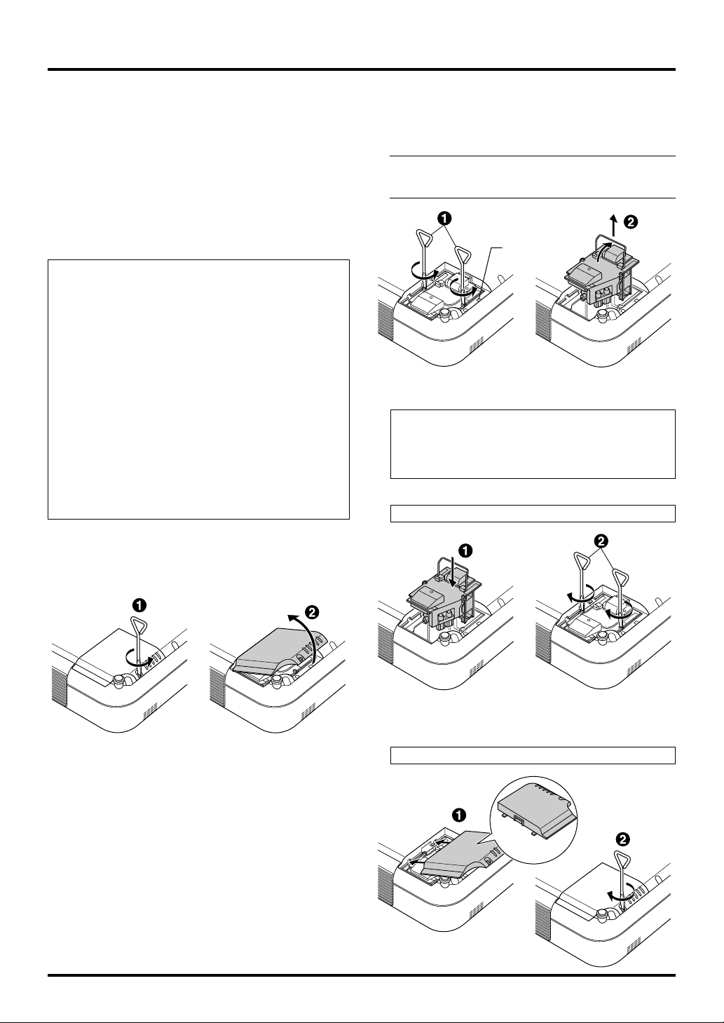
4. MAINTENANCE
This section describes the simple maintenance procedures you
should follow to replace the lamp, clean the filters, and replace
the batteries in the remote control.
Replacing the Lamp
After your lamp has been operating for 1000 hours (up to 2000
hours in Eco 2 mode and up to 1500 hours in Eco 1 mode) or
longer, the “Status” light in the cabinet will go on and the message will appear. Even though the lamp may still be working,
replace it at 1000 (up to 2000 hours in Eco 2 mode and up to
1500 hours in Eco 1 mode) hours to maintain optimal projector
performance.
CAUTION
•
DO NOT TOUCH THE LAMP immediately after it has been
used. It will be extremely hot. Turn the projector off, wait
60 seconds, and then disconnect the power cable. Allow at
least one hour for the lamp to cool before handling.
• DO NOT REMOVE ANY SCREWS except the lamp
cover screw and two lamp case screws. You could receive an electric shock.
The projector will turn off and go into stand by mode after
•
1100 (up to 2100 hours in Eco 2 mode and up to 1600 hours
in Eco 1 mode) hours of service. If this happens, be sure to
replace the lamp. If you continue to use the lamp after 1100
hours (up to 2100 hours in Eco 2 mode and up to 1600 hours
in Eco 1 mode) of use, the lamp bulb may shatter, and pieces
of glass may be scattered in the lamp case. Do not touch
them as the pieces of glass may cause injury. If this happens, contact your NEC dealer for lamp replacement.
To replace the lamp:
1. Loosen the lamp cover screw until the screwdriver goes into
a freewheeling condition and remove the lamp cover. The
lamp cover screw is not removable.
2. Loosen the two screws securing the lamp housing until the
screwdriver goes into a freewheeling condition. The two
screws are not removable.
Remove the lamp housing by pulling out the handle.
NOTE: There is an interlock on this case to prevent the risk
of electrical shock. Do not attempt to circumvent this interlock.
Interlock
3. Insert a new lamp housing until the lamp housing is plugged
into the socket.
CAUTION
Do not use a lamp other than the NEC replacement lamp
(VT45LP).
Order this from your NEC dealer.
Secure it in place with the two screws.
Be sure to tighten the screws.
4. Reattach the lamp cover.
Tighten the lamp cover screw.
Be sure to tighten the screw.
E–36

5. After you install a new lamp, select [Advanced Menu] →
[Projector Options]→[Setup]→[Page 4]→[Clear Lamp Hour
Meter] to reset the lamp usage hours.
NOTE: When the lamp exceeds 1100 hours (up to 2100 hours in
Eco 2 mode and up to 1600 hours in Eco 1 mode) of service, the
projector cannot turn on and the menu is not displayed. If this
happens, press the Help button on the remote control for a minimum of 10 seconds while in standby mode. When the lamp time
clock is reset to zero, the STATUS indicator goes out.
Cleaning or Replacing the Filters
The air-filter sponge keeps the inside of the VT45 Projector free
from dust or dirt and should be cleaned after every 100 hours of
operation (more often in dusty conditions). If the filter is dirty or
clogged, your projector may overheat.
CAUTION
• Turn off the power and unplug the projector before
replacing the filter.
• Only clean the outside of the filter cover with a
vacuum cleaner.
• Do not attempt to operate the projector without a
filter cover.
• Your projector will not operate unless the filter cover
is installed correctly.
To clean the air-filter:
When “Clean Filter” option is turned on, the “Please clean the
filters” message will be displayed each time the projector is turned
on after it has been used in excess of 100 hours. Should this
message appear, clean the filters.
• The message can be turned on or off using the “Menu” - “Filter Clean Message” option on the Setup menu. See page E-
33.
• After cleaning the filters and resetting the filter usage time
back to zero, the message will not be displayed.
See page E-35 for resetting the filter usage time.
Vacuum the filter-through the filter cover.
U
N
E
M
L
E
C
N
SELECT
A
C
R
E
T
N
E
AUTO ADJUST
STATUS
STAND BY
POWER
SOURCE
ON
To replace the air-filter:
1. Remove the filter cover by pushing up on the catch of the
cover until you feel it detach.
U
N
E
M
L
E
C
N
SELECT
A
C
R
E
T
N
E
T
JUS
O AD
AUT
ATUS
R
D BY
E
E
ST
RC
STAN
POW
N
SOU
O
U
N
E
M
L
E
C
N
SELECT
A
C
R
E
T
N
E
T
S
JU
D
A
O
T
U
S
Y
A
U
B
T
A
R
D
T
E
N
S
A
W
T
O
RCE
S
P
N
SOU
O
2. Reinstall the new filter cover.
NOTE: Do not detach the sponge from the filter cover. Do not
wash the filter cover with soap and water. Soap and water will
damage the the filter membrane. Before replacing the filter cover,
remove dust and dirt from the projector cabinet. Keep out dust
and during filter replacement.
NOTE: When you replace the lamp, it is also wise to replace the
filters. The filters come in the same package with your replacement lamp.
NOTE: A mix-up between the two filter covers can cause a damage to the projector.
The front and the side filter covers appear to be the same shape,
but they are not interchangeable with each other.
E–37

5. TROUBLESHOOTING
This section helps you resolve problems you may encounter while setting up or using the projector.
Power/ Status Light Messages
Condition
Standby
Cooling down
Lamp in Nomal mode
Lamp in Eco 1 mode
Lamp in Eco 2 mode
One minute after lamp is turned on
Retrying to turn on lamp
Lamp has reached its end of life
(1000 hours or over: Normal mode)
(1500 hours or over: Eco 1 mode)
(2000 hours or over: Eco 2 mode)
Lamp life has reached its end of life
(1100 hours or over: Normal mode)
(1600 hours or over: Eco 1 mode)
(2100 hours or over: Eco 2 mode)
Lamp or filter cover error (3 locations)
Temperature error
Fan error
Lamp error
Power Indicator Status Indicator Note
Steady orange
Blinking green
Steady green
Steady green
Steady green
Blinking green
Steady green
Steady green
Steady orange
Steady orange
Steady orange
Steady orange
Steady orange
–
–
–
Steady orange
Steady green
Depending Lamp mode
Blinking orange
Steady red
Steady red
Blinking red (1 sec interval)
Blinking red (4 sec interval)
Blinking red (8 sec interval)
Blinking red (12 sec interval)
–
Blinks green for 60 seconds
–
–
–
Do not turr off the projector during this
condition.
The projector retries 3 times at an interval of 15 sec for max. 45 sec)
Message appears on screen during
this condition. The projector reaches
its end of life. Please replace the lamp
as soon as possible
The projector is in standby mode and
cannot be turned on.
The projector is in standby mode and
cannot be turned on.
The projector is in standby mode and
cannot be turned on.
The projector is in standby mode and
cannot be turned on.
The projector is in standby mode and
cannot be turned on.
Common Problems & Solutions
Problem
Does not turn on
No picture
Image isn’t square to the
screen
Picture is blurred
Image is scrolling vertically,
horizontally or both
Remote control does not
work
Status indicator is lit or
blinking
Cross color in RGB mode
Check These Items
• Check that the power cable is plugged in and that the power button on the projector cabinet or the
remote control is on.
• Ensure that the lamp cover is installed correctly. See page E-36.
• Check to see if the projector has overheated or the lamp usage exceeds 1100 hours (2100 hours in
Eco 2 mode and 1600 hours in Eco 1 mode). If there is insufficient ventilation around the projector or
if the room where you’re presenting is particularly warm, move the projector to a cooler location.
• Use the menu to select your source (Video, S-Video or RGB). See page E-29.
• Ensure your cables are connected properly.
• Use menus to adjust the brightness and contrast. See page E-29.
• Remove the lens cap.
• Reset the settings or adjustments to factory preset levels using the Factory Default on the Image
Options Menu. See page E-31.
• Reposition the projector to improve its angle to the screen. See page E-14.
• Use the Keystone on the Image Options Menu to correct the trapezoid distortion. See page E-29.
• Adjust the focus. See page E-23.
• Reposition the projector to improve its angle to the screen. See page E-14.
• Ensure that the distance between the projector and screen is within the adjustment range of the lens.
See page E-15.
• Use menus or Source button on the remote control or the cabinet to select the source you want to
input.
• Install new batteries. See page E-13.
• Make sure there are no obstacles between you and the projector.
• Stand within 22 feet (7 m) of the projector. See page E-13.
• See the Power/ Status Light messages above.
• If Auto Adjust is off, turn it on. If Auto Adjust is on, turn it off and balance the image with the Position
and Clock Adjust on the Advanced Options Menu. See page E-31.
E–38

6. SPECIFICATIONS
This section provides technical information about the VT45 Projector’s performance.
Model Number VT45
Optical
LCD Panel 0.7” p-Si TFT active-matrix, 800600 dots
Lens Manual zoom, manual focus
F2.0 – 2.2 f=26.7 – 29.3 mm
Lamp 135W NSH lamp (120W in Eco 1 mode and 110W in Eco 2 mode)
The lamp is warranted for 1000 hours of operation time within 6 months.
Image Size 25 – 300 inches (0.64 – 7.62 m) diagonal
Projection Distance 3.3 – 39.4 ft (1.0 – 11.2 m)
Electrical
Inputs Video (NTSC / PAL / PAL-M / PAL-N / PAL60 / SECAM / NTSC4.43)
Horizontal Frequency : 15 – 100 kHz
Vertical Frequency : 50 – 120 Hz
Video Bandwidth RGB: 80 MHz
Color Reproduction Full color, 16.7 million colors simultaneously.
Horizontal Resolution 550 TV lines : NTSC / PAL / NTSC4.43 / YCbCr
350 TV lines : SECAM
RGB : 800 dots horizontal, 600 dots vertical
Power Requirement 100 – 120 / 200 – 240 VAC, 50 / 60 Hz
Input Current 2.5 A (100 – 120 VAC) / 1.2A (200 – 240 VAC)
Power Consumption 200 W (185 W in Eco 1 : 175W in Eco 2)
Mechanical
Dimensions
Net Weight 5.6 lbs / 2.5 kg
Environmental Considerations
Regulations UL Approved (UL 1950, CSA 950)
We provide more information about our projectors through the World Wide Web at http://www.nec-pj.com/
LCD panels are inherently susceptible to bad pixels.
The LCD panel may have pixel failures at the rate of 0.01%or less.
The specifications are subject to change without notice.
11.8" (W)3.3" (H)8.1" (D) / 299 mm (W)85 mm (H)207 mm (D) (not including lens and
feet)
Operational Temperatures: 32˚ – 95˚F (0˚ to 35˚C), 20 – 80% humidity (non-condensing)
Storage Temperatures: 14˚ – 122˚F (-10˚ to 50˚C), 30 – 85% humidity
Meets DOC Canada Class B requirements
Meets FCC Class B requirements
Meets AS/NZS3548 Class B
Meets EMC Directive (EN55022, EN55082-1, EN61000-3-2, EN61000-3-3)
Meets Low Voltage Directive (EN60950, TUV GS Approved)
E–39
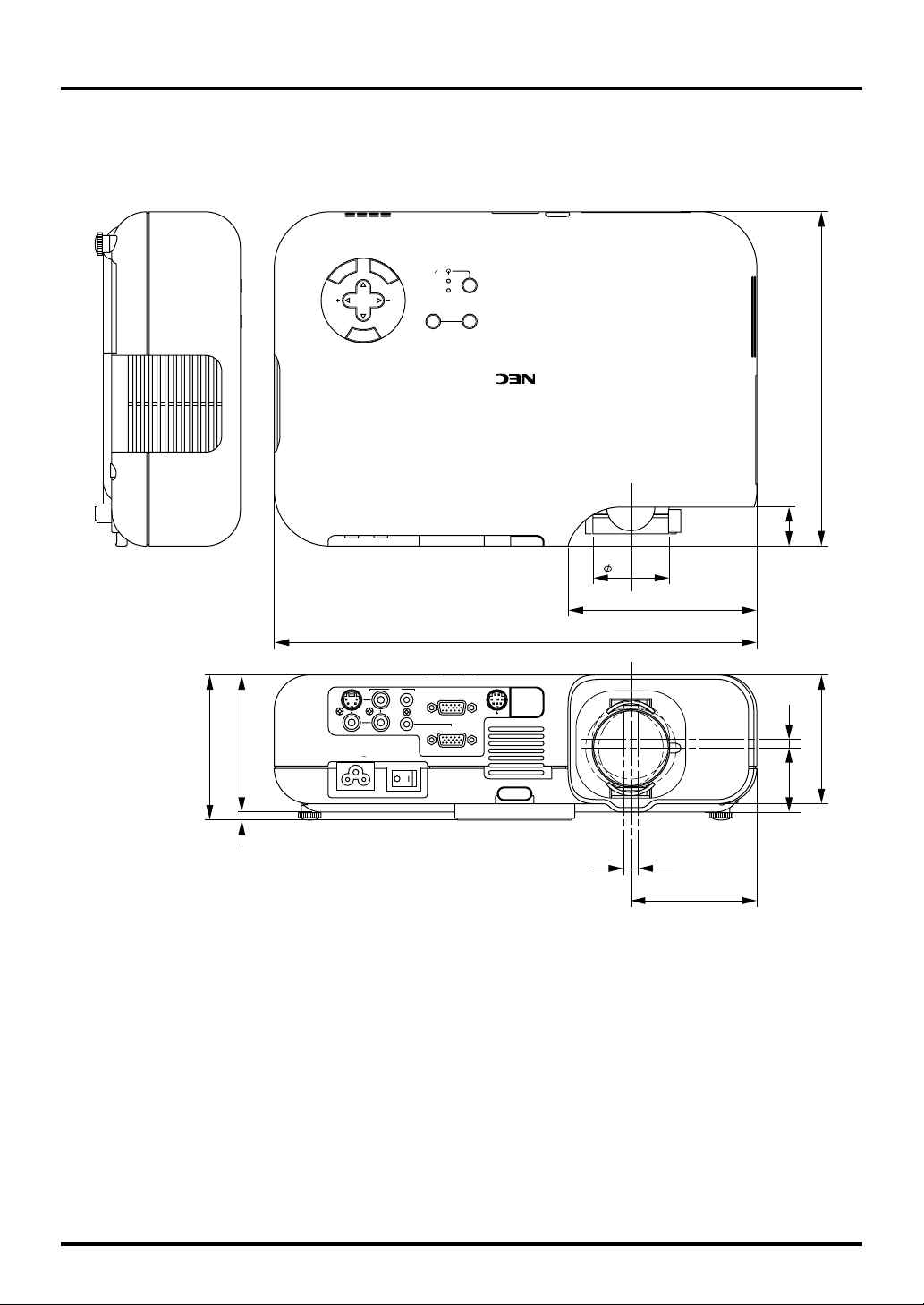
Cabinet Dimensions
VT45
85(3.35")
90(3.54")
S-VIDEO
VIDEO
CANCEL
SELECT
MENU
ENTER
STAND BY
ON
POWER
STATUS
AUTO ADJUST
SOURCE
207(8.15")
24
(0.94")
47(1.85")
117(4.61")
299(11.77")
AUDIO
IN
L/MONO
OUT
IN
IN
AC IN
IN
R
IN
RGB OUT
PC
CONTROL
RGB IN
VT
45
5.4(0.21")
80(3.15")
39.6
(1.56")
5(0.2")
4.6(0.18")4.6(0.18")
78(3.07")
Unit = mm (inch)
E–40

D-Sub Pin Assignments
Mini D-Sub 15 Pin Connector
51423
10
6978
1112131415
Signal Level
Video signal : 0.7Vp-p (Analog)
Sync signal : TTL level
Pin No. RGB Signal (Analog) YCbCr Signal
1 Red Cr
2 Green or Sync on Green Y
3 Blue Cb
4 Ground
5 Ground
6 Red Ground Cr Ground
7 Green Ground Y Ground
8 Blue Ground Cb Ground
9 No Connection
10 Sync Signal Ground
11 Ground
12 Bi-directional DATA (SDA)
13 Horizontal Sync or Composite Sync
14 Vertical Sync
15 Data Clock
E–41

Timing Chart
Y / N Signal Resolution Frequency H. Refresh Rate Dot Clock
( Dots ) ( kHz ) ( Hz ) ( MHz )
Y NTSC 640 480 15.734 60 Y PAL 768 576 15.625 50 Y SECAM 768 576 15.625 50 Y VESA 640 480 31.47 59.94 25.175
Y IBM 640 480 31.47 60 25.175
Y MAC 640 480 31.47 60 25.175
Y MAC 640 480 34.97 66.67 31.334
Y MAC 640 480 35 66.67 30.24
Y VESA 640 480 37.86 72.81 31.5
Y VESA 640 480 37.5 75 31.5
Y IBM 640 480 39.375 75 31.49
Y VESA 640 480 43.269 85.01 36
Y IBM 720 350 31.469 70.09 28.322
Y VESA 720 400 37.927 85.04 35.5
Y IBM 720 350 39.44 87.85 35.5
Y IBM 720 400 39.375 87.7 35.5
Y VESA 800 600 35.16 56.25 36
Y VESA 800 600 37.879 60.32 40
Y VESA 800 600 48.077 72.19 50
Y VESA 800 600 46.88 75 49.5
Y VESA 800 600 53.674 85.06 56.25
#Y MAC 832 624 49.725 74.55 57.283
#Y VESA 1024 768 35.5 43 Interlaced 44.9
#Y VESA 1024 768 48.363 60 65
#Y VESA 1024 768 57.476 70.07 75
#Y IBM 1024 768 58.131 72.03 79
#Y MAC 1024 768 60.241 74.93 80
#Y VESA 1024 768 60.023 75.03 78.75
#Y VESA 1024 768 68.677 85 94.5
#Y VESA 1152 864 67.5 75 108
#Y MAC 1152 870 68.681 75.06 100
#Y SUN 1152 900 61.796 65.95 92.94
#Y SGI 1152 900 71.736 76.05 105.6
#Y VESA 1280 960 60 60 108
#Y SGI 1280 1024 63.9 60 107.35
#Y VESA 1280 1024 63.981 60.02 108
#Y MAC 1280 1024 64.31 60.38 107
#Y MAC 1280 1024 69.9 65.2 118.5
#Y HP 1280 1024 78.125 72.01 135
#Y SUN 1280 1024 81.13 76.11 135
#Y VESA 1280 1024 79.976 75.03 135
#Y VESA 1280 1024 91.146 85.02 157.5
#Y
HDTV (1080i)(1125i)
#Y
HDTV (720p)(750p)
#Y
SDTV (480p)(525p)
#Y
SDTV (480i)(525i)
#Y: Images in above flagged with # and Y are compressed with Advanced AccuBlend.
NOTE1: Some composite sync signals may not be displayed correctly.
NOTE2: Signals other than those specified in the table above may not be displayed correctly. If this should happen, change the refresh rate or resolution on
your PC. Refer to Display Properties help section of your PC for procedures.
1920 1080 33.75 60 Interlace 74.25
1280 720 45 60 Progressive 74.25
– 31.47 59.94 Progressive 27
– 15.73 59.9 Interlace –
E–42

12
54 3
6
7
8
PC Control Codes
Function Code Data
POWER ON 02H 00H 00H 00H 00H 02H
POWER OFF 02H 01H 00H 00H 00H 03H
INPUT SELECT RGB 02H 03H 00H 00H 02H 01H 01H 09H
INPUT SELECT VIDEO 02H 03H 00H 00H 02H 01H 06H 0EH
INPUT SELECT S-VIDEO 02H 03H 00H 00H 02H 01H 0BH 13H
PICTURE MUTE ON 02H 10H 00H 00H 00H 12H
PICTURE MUTE OFF 02H 11H 00H 00H 00H 13H
SOUND MUTE ON 02H 12H 00H 00H 00H 14H
SOUND MUTE OFF 02H 13H 00H 00H 00H 15H
ON SCREEN MUTE ON 02H 14H 00H 00H 00H 16H
ON SCREEN MUTE OFF 02H 15H 00H 00H 00H 17H
Cable Connection
Communication Protocol
Baud rate: 19200 bps
Data length: 8 bits
Parity: No parity
Stop bit: One bit
X on/off: None
Communications
procedure:
PC Control Connector (DIN-8P)
Full duplex
To RxD of PC
NOTE: Contact your local dealer for a full list of the PC Control Codes if needed.
To GND of PC
NOTE: Pins 2, 3, 5, 6 and 8 are used inside the projector.
To TxD of PC
E–43
 Loading...