


NDA-24230
DOI-E10504
ISSUE 2
STOCK # 0293884
VisuaLink 128/384
User Guide
DECEMBER, 1998
NEC America, Inc.

LIABILITY DISCLAIMER
NEC America, Inc. reserves the right to change the specifications,
functions, or features, at any time, without notice.
NEC America, Inc. has pr ep ared thi s doc um ent for u se by i ts employees and custom ers. The information conta ined herein is the
property of NEC America, Inc. and shall not be reproduced without
prior written approval from NEC America, Inc.
Copyright 1998
NEC America, Inc.
Printed in USA

EXHIBIT J1
FCC REQUIREMENTS
NEC America, Inc.
VisuaLink 128/VisuaLink 384
TYPE OF SERVICE
The VisuaLink 128 and the VisuaLink 384 are stand-alone devices that allow multimedia conferencing by
transmitting video, a udi o an d dat a t o r emote locations over the ISDN Basic Rat e in terface. The VisuaLink 128
and VisuaLink 384 connect to the ISDN digital network through separately-registered NTI equipment. They
provide POTS ports which allow a customer-provided 2500-type telephone access to the digital network.
This equipment complies with Part 68 of the FCC Rules. The equipment label will appear on the rear exterior
panel of the unit and will provide the FCC Registration Number, NEC trade name, model number, serial
number or date of manufacture and the country of origin.
TELEPHONE COMPANY PROCEDURES
The goal of the telephone company is to provide you with the best service it can. In order to do this, it may
occasionally be necessary for them to make changes in their equipment, operations, or procedures. If these
changes might affect your service or the operation of your equipment, the telephone company will give you
notice, in writing, to allow you to make any changes necessary to maintain uninterrupted service.
If you have any questi ons about your tele phone lin e, such as h ow many piece s of equip ment you can connect t o
it, the telephone company will give you notice, in writing, to allow you to make any changes necessary to
maintain uninterrupted service.
In certain circumstances, it may be necessary for the telephone company to request from you concerning the
equipment which you have connecte d to your telephone line. Upon request of the telep hone company, provide
the FCC registration numbe r and the ri nger equivalen ce number (REN) of the equi pment which i s connected to
your line; both of these items are listed on the equipment label The sum of all of the REN's on your telephone
lines should be less than five in order to assure proper service from the telephone company. In some cases, a
sum of five may not be usable on a given line.

IF PROBLEMS ARISE
If any of your telephone equipment is not operating properly, you should immediately remove it from your
telephone lines, as it may cau se harm to the tele phone ne twork. If the telephon e company not es a prob lem, they
may temporarily discontinue service. When practical, they will notify you in advance of this disconnection. If
advance notice is not feasible, you will be notified as soon as possible. When you are notified, you will be
given the opportunity to correct the problem and informed of your right to file a complaint with the FCC.
In the event repairs are ever needed on your Visualink 128 or VisuaLink 384, they should be performed by
NEC America, Inc. or an authorized representative of NEC America, Inc. For information contact:
NEC America, Inc.
1555 W. Walnut Hill Lane
Irving, Texas 75038-3797
USA
972-751-7000
FCC REQUIREMENTS FOR CONNECTION OF TELEPHONE SYSTEMS
In order to connect this system to the telephone network, provide the telephone company with:
• the quantities and USOC numbers of the required jacks (shown below);
• the sequence in which the trunks are to be connected;
• the facility interface codes by position; and
• the ringer equivalence number or service code, as applicable, by position
MFG’s Port IDUSOC Jack
Connector
VisuaLink 128 N/A 6.0P 02IS5 1 1 AY5JPN-32617-XD-N
VisuaLink 384 N/A 6.0P 02IS5 3 1 AY5JPN-32617-XD-N
REN/Service
Code
Facility Interface
Code
# CO
Ports
# Stations Registration #

CSA Requirement
To ensure that certified equipment is attached correctly, and only to the networks of participating carriers, the
following statement shall accompany each unit of certified equipment offered for sale. This statement must be
included conspicuously in written or electronic format, at or near the front of each copy of the operating
manual, or accompany other technical information, or be included as a separate sheet. The required statement
is:
CP-01, Issue 8, Part I
Section 14.1
NOTICE
: The Industr y Canada label identifies certified equipment. This certification means th at the
equipment meets certain telecommunications network protective, operational and safety requirements as
prescribed in the app ropri ate Terminal Equipment Technical Requirements document(s ). The Dep artment does
not guarantee the equipment will operate to the user's satisfaction.
Before installing this equipment, users should ensure that it is permissible to be connected to the facilities of
the local telecommunications company. The equipment must also be installed using an acceptable method of
connection. The customer should be aware that compliance with the above conditions may not prevent
degradation of service in some situations.
Repairs to certified equipment should be coordinated by a representative designated by the supplier. Any
repairs or alterations made by the user to this equipment, or equipment malfunctions, may give the
telecommunications company cause to request the user to disconnect the equipment.
Users should ensure for their own protection that the electrical ground connections of the power utility,
telephone lines and inte rnal metal lic water pipe s ystem, if pres ent, are conn ected togethe r. This precaution may
be particularly important in rural areas.
CAUTION:
Users should not attempt to make such connections themselves, but should contact the
appropriate electric inspection
MODEL CERTIFICATE NUMBER CERTIFICATION NUMBER
VisuaLink 128 19318 140 9004A
VisuaLink 384 19603 140 9104A


VisuaLink 128/384 User Guide Table of Contents
Table of Contents
Chapter 1 Introducing Your VisuaLink................................................................ 1-1
Applying for ISDN BRI ........................................................................................................ 1-1
Unpacking........................................................................................................................... 1-2
Chapter 2 Introduction of VisuaLink.................................................................... 2-1
About your VisuaLink.......................... .. .. .. .. .. .................................... .. .. .. ............................ 2-1
Front Panel Description ...................................................................................................... 2-2
VisuaLink 128 Rear Panel Description ..................... .......................... .......................... ...... 2-3
VisuaLink 384 Rear Panel Description ..................... .......................... .......................... ...... 2-4
Remote Contro lle r.................. .. .............. .. ............. .. .............. .. ............. .. .............. .. ............. 2-9
Chapter 3 Initial Setting and Operation Checking.............................................. 3-1
Chapter 4 Application Setup................................................................................. 4-1
Guidelines........................................................................................................................... 4-1
Hardware .............. .. ............. .. .............. .. ............. .. ............. ... ............. .. ............. ... ............... 4-2
Software Setu p ........... ............. ... ............. .. ............. ... ............. .. ............. ... ............. .. ......... 4-23
Setting Up your ISDN Line Information............................................. .......................... .. .... 4-24
Optional User Settings ...................................................................................................... 4-27
Chapter 5 System Parameter/Environment Setting............................................ 5-1
Environment Setting Menu.................................................................................................. 5-1
Video Setting....................................................................................................................... 5-6
Audio Setting....................................................................................................................... 5-8
Data Setting . ............. .. ............. ... ............. .. ............. ... ............. .. ............. ... ............. .. ......... 5-11
Communication Setting..................................................................................................... 5-13
Local Setting ..................................................................................................................... 5-15
Maintenance Settings ....................................................................................................... 5-29
Chapter 6 About Calling........................................................................................ 6-1
Place a Manual Call........................................... .. .......................... ..................................... 6-1
Set Speed Dial Nu mb e r ....................... ............. .. ............. .. .............. .. ............. .. .............. .. .. 6-6
End a Call ......................................................................................................................... 6-1 6
Answer a Call.................................................................................................................... 6-17
Chapter 7 Conference Mode................................................................................. 7-1
How to Display the Conference Mode On-Screen Icons .................................................... 7-1
Picture-in-Picture Menu ...................................................................................................... 7-4
Camera Preset Me n u......... .. ............. ... ............. .. ............. .. .............. .. ............. .. .............. .. .. 7-7
Audio Conditioning.................................... .. .. .................................... .. .. .. .......................... 7-10
NDA-24230 Issue 2.0 Page i

T a b le of Conten ts VisuaLink 128/384 User Guide
Chapter 8 Operation Method................................................................................. 8-1
System Status..................................................................................................................... 8-1
Volume Control ...... .. ... ............. .. ............. ... ............. .. ............. .. .............. .. ............. .. ............ 8-3
Muting Your Microphone..................................................................................................... 8-4
Switching Monitor Screens................................................................................................. 8-5
Switching Camera Pictures................................................................................................. 8-7
PIP Functions.....................................................................................................................8-10
Send a Snapshot ...................... .......................... ................................................. .. ........... 8-11
Camera Functions.......................................... .......................... ......................... ............... 8-13
Using Camera Preset........................................................................................................ 8-16
Pointer Display.................................................................................................................. 8-17
Chapter 9 VisuaLink Troubleshooting Guide...................................................... 9-1
Appendix A Audio/Data/Video Bit Rate Assignment Table.................................. A-1
Appendix B Software Upgrade Instructions .......................................................... B-1
Appendix C CALL Menu Structure.......................................................................... C-1
Appendix D How to Order ISDN BRI....................................................................... D-1
Page ii NDA-24230 Issue 2.0

List of Figures VisuaLink 128/384 User Guide
List of Figures
Figure 4-1: Connection Diagram for VisuaLink 128.................... ..... .... .................. 4-2
Figure 4-2: Connection Diagram for VisuaLink 384.................... ..... .... .................. 4-3
Figure 4-3: Connection Diagram for VisuaLink 128.................... ..... .... .................. 4-5
Figure 4-4: Connection Diagram for VisuaLink 384.................... ..... .... .................. 4-6
Figure 4-5: Connection Diagram for VisuaLink 128.................... ..... .... .................. 4-9
Figure 4-6: Connection Diagram for VisuaLink 384............................. ..... ..... ...... 4-10
Figure 4-7: Equipment Placement ......................................................................... 4-12
Page iii NDA-24230 Issue 2.0

List of Tables VisuaLink 128/384 User Guide
List of Tables
Table 1-1: Parts List for the VL128 and VL384..................................................... 1-2
Table 1-2: Optional parts to be provided.............................................................. 1-3
Table 2-1: VisuaLink 128 and VisuaLink 384 General Parameters.................... 2-5
Table 2-2: VisuaLink 128 and VisuaLink 384 External Interface Parameters.... 2-7
Table 9-1: Troubleshooting Guide........................................................................ 9-1
Page iv NDA-24230 Issue 2.0

VisuaLink 128/384 User Guide Chapter 1
Chapter 1 Introducing Your VisuaLink
1.1 Applying for ISDN
BRI
This device cannot be used unless a connection to
Line
is provided. Verify that a ISDN line exists before the CODEC is installed.
What to watch out for when filling out an ISDN BRI application:
As defined by Bellcore; the ISDN BRI simplified ordering code is EZ-ISDN1.
• The ISDN BRI protocol national ISDN-1.
• The ISDN BRI service must be tariffed and available from the customer’s
local central office.
• The D-Channel should not permit X.25 packet data.
• The ISDN BRI service must allow videoconferencing calls to be dialed on
either B-Channel or on both simultaneously.
• Both B-Channel must carry circuit switched videoconferencing data.
• The ISDN BRI line required one or two different SPID numbers.
• The ISDN BRI service must be automatic Terminal Endpoint Identifiers
(TEIs).
Voice and data features:
• Flexible ca lling
• Call forwarding variable
ISDN BRI Communication
• Additional call offering
• Call number identification
• Redirecting number delivery
How to Order ISDN BRI Guide
A
thoroughly and forwarded to your Teleco provider. This document is located in
Appendix D
the
.
has been prepared. This guide sho uld be rea d
NDA-24230 Issue 2.0 Page 1-1
Chapter 1 VisuaLink 128/384 User Guide
1.2 Unpacking
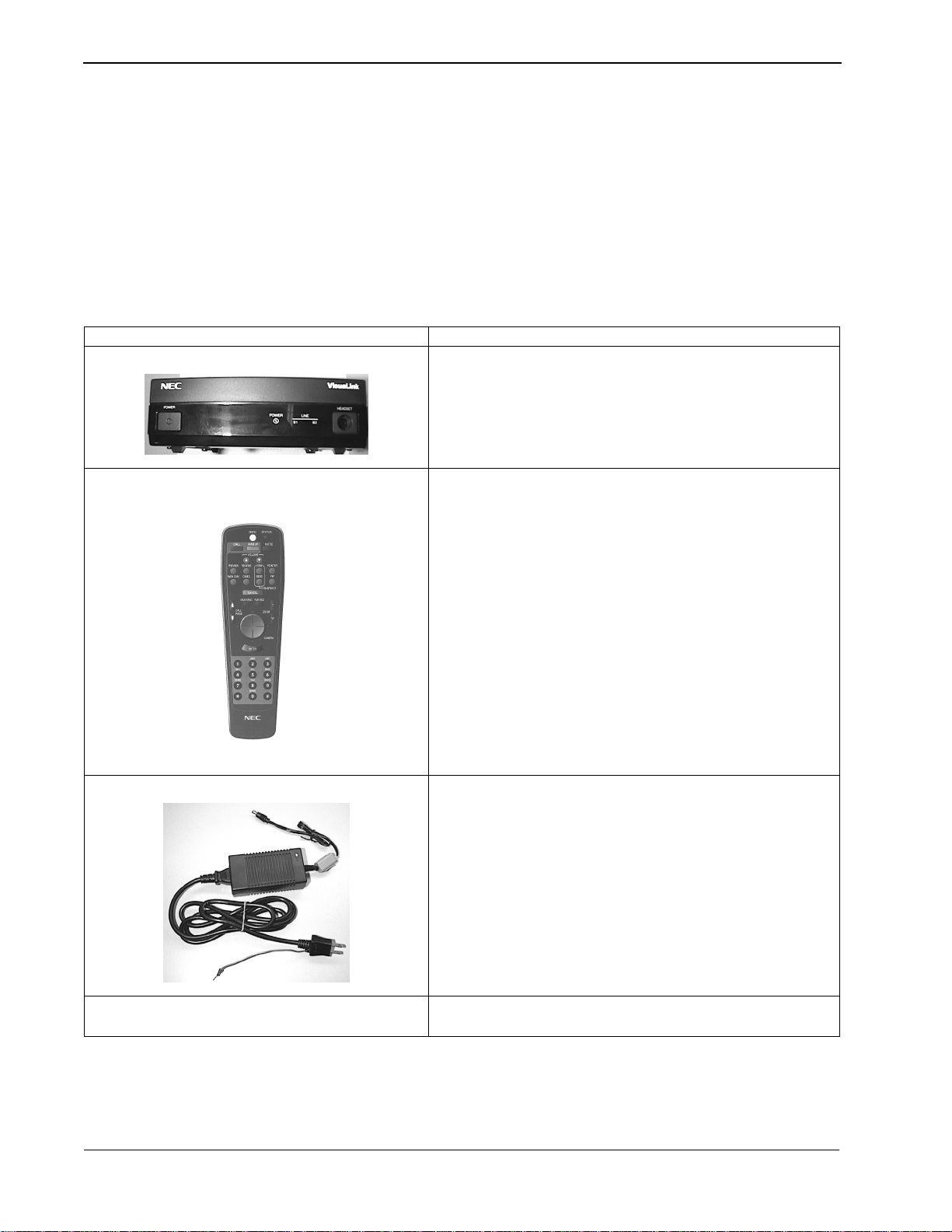
Item Description
(A) Main Unit
(B) Remote controller and batteries
• Opening the Box
Please take out the device wit hout giv ing any impac t on it when ope ning the box.
Please keep the box after opening it, since you may use it when you send the
device for repair, maintenance and/or travel.
• The Contents of the Package
The VisuaLink 128 and VisuaLink 384 package contains the following items.
Please verify these items are contained the box.
Table 1-1: Parts List for the VL128 and VL384
This is the main unit of the VisuaLink 128 or VisuaLink 384.
This is a remote controller use d to control the VisuaL ink 128 or
VisuaLink 384. Two AA batteries are also included.
(C) AC Adapter
This is an AC adapter for VisuaLink 128 or VisuaLink 384.
(D) VisuaLink 128/384 User Guide Provides procedures for installation, operations and
maintenance of the VisuaLink 128 and VisuaLink 384.
Page 1-2 NDA-24230 Issue 2.0
VisuaLink 128/384 User Guide Chapter 1
Table 1-1: Parts List for the VL128 and VL384 (continued)
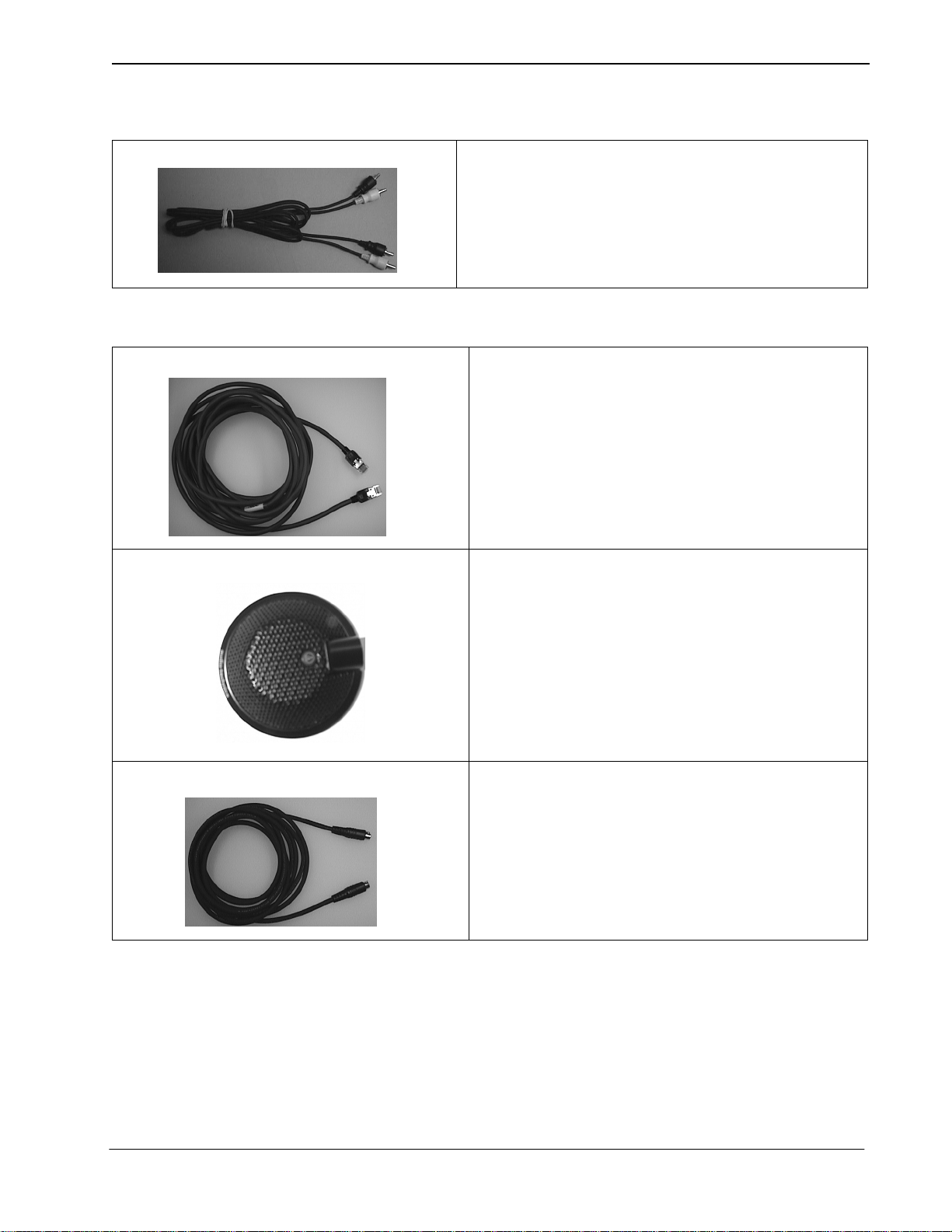
(E) Audio Video Cable
This cable is used to connect peripheral devices such as
camera and TV to the VisuaLink 128 or VisuaLink 384.
Table 1-2: Optional parts to be provided
(A) BRI Network Cable
This cable is used to c onnec t the VisuaL ink 1 28 or VisuaL ink
384 to an ISDN BRI network.
Three (3) cables are required for a VisuaLink 384.
Note:
(B) Microphone
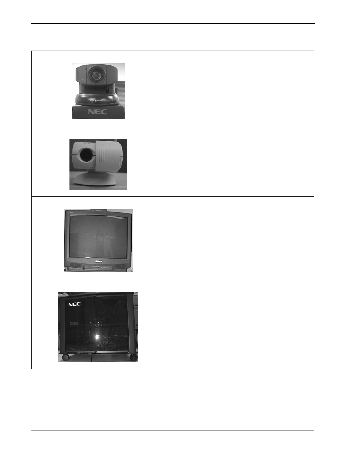
(C) Video Cable
The microphone co nnect s to th e rear o f the Vis uaLin k 128 or
VisuaLink 384. There are 3 microphone inputs.
This cable is used to c onnec t the VisuaL ink 1 28 or VisuaL ink
384 S-Video (output video) to a TV monitor.
NDA-24230 Issue 2.0 Page 1-3
Chapter 1 VisuaLink 128/384 User Guide
Table 1-2: Optional parts to be provided (continued)
(D) Camera
A pan/tilt zoom focus camera that provides a video image shot
to the far-site.
Used in the turnkey rollabout configurations.
Note:
(E) PC Camera
A fixed camera used to provide a one or two person shot to
the far site.
Used in the desktop application.
Note:
(F) Monitor
(G) Cabinet
A TV monitor to provide for viewing of the far-site.
Provided with the turnkey rollabout configuration.
Note:
A equipment stand to house all the Rollabout peripherals
such as the VisuaLink and NT1’s.
Cabinet is used f or the turnk e y rollab out con figur ati on.
Note:
Page 1-4 NDA-24230 Issue 2.0

VisuaLink 128/384 User Guide Chapter 2
Chapter 2 Introduction of VisuaLink
2.1 About your VisuaLink
The VisuaLink 128 and the VisuaLink 384 are devices that easily realize a
multimedia confere nce by trans mit ting v ide o, audi o, and d ata t o a remote lo catio n
with the use of BRI service. The VisuaLink 128 and VisuaLink 384 provide a
low-end TV conference for a small group of people when connected to a handsfree telephone. In addition, with a connection with a PC, a TV conference using
data conference application such as an electric presentation will be available. The
VisuaLink 128 and VisuaLink 384 also provide a high-performance model with a
built-in echo canceller applicable for video conferences with microphones and
speakers in a conference room.
2.1.1 The characteristics of VisuaLink 128 are
• You can use it as a high quality TV phone by connecting a TV, telephone, and
video camera.
• You can use it as a serious business videoconference system by connecting
optional video camera, microphone, and speakers.
• You can easily operate it from a telephone or a remote controller.
• You can connect any PC model for a conference with a PC. (However, a data
conference software is required in your PC. Please contact to sales rep. to get
information fo r what ty pe of software is availa bl e fo r the data conference with
the VL128.
2.1.2 The characterist ics of V isuaLin k 384 are the same as those fo r the V isuaLink
128 listed above, plus
• It has an internal IMUX.
• You can connect to three (3) NT-1s.
NDA-24230 Issue 2.0 Page 2-1

Chapter 2 VisuaLink 128/384 User Guide
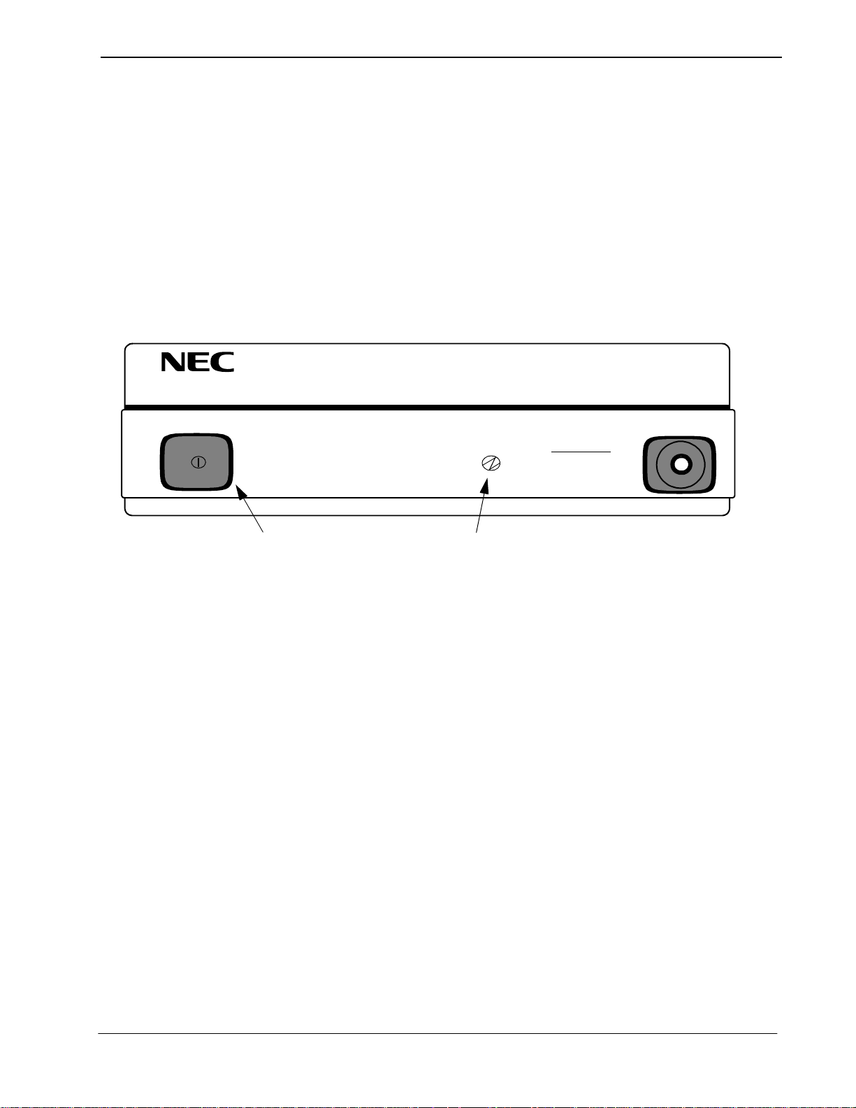
2.2 Front Panel Description
POWER HEADSET
This section briefly describes names and features of the VisuaLink 128 and
VisuaLink 384.
POWER
LINE
B1 B2-B6
①
①
POWER
Switch
➁
➂
➃
The push-button switch is used to turn on and off the main power. When the
power is on, the power lamp will be lit.
➁
Remote controller optical receiver
This is a optical receiver, which receives signal from remote controller.
➂
LED Display
Power Lamp (power) : a green light will eluminate when the power is ON.
When the VisuaLink is powered OFF, there is no light.
Line connection status lamp (LINE)
LINE B1: Flashing light indicates channel is calling to the remote end.
Steady light indicates connection/communicating with the remote end.
LINE B2-B6: Flashing lig ht indicates channel is ca lling to the remote end.
Steady light indicates connection/communicating with the remote end.
➃
Head set terminal
The head set jack is used to connect an optional headset.
Page 2-2 NDA-24230 Issue 2.0
VisuaLink 128/384 User Guide Chapter 2
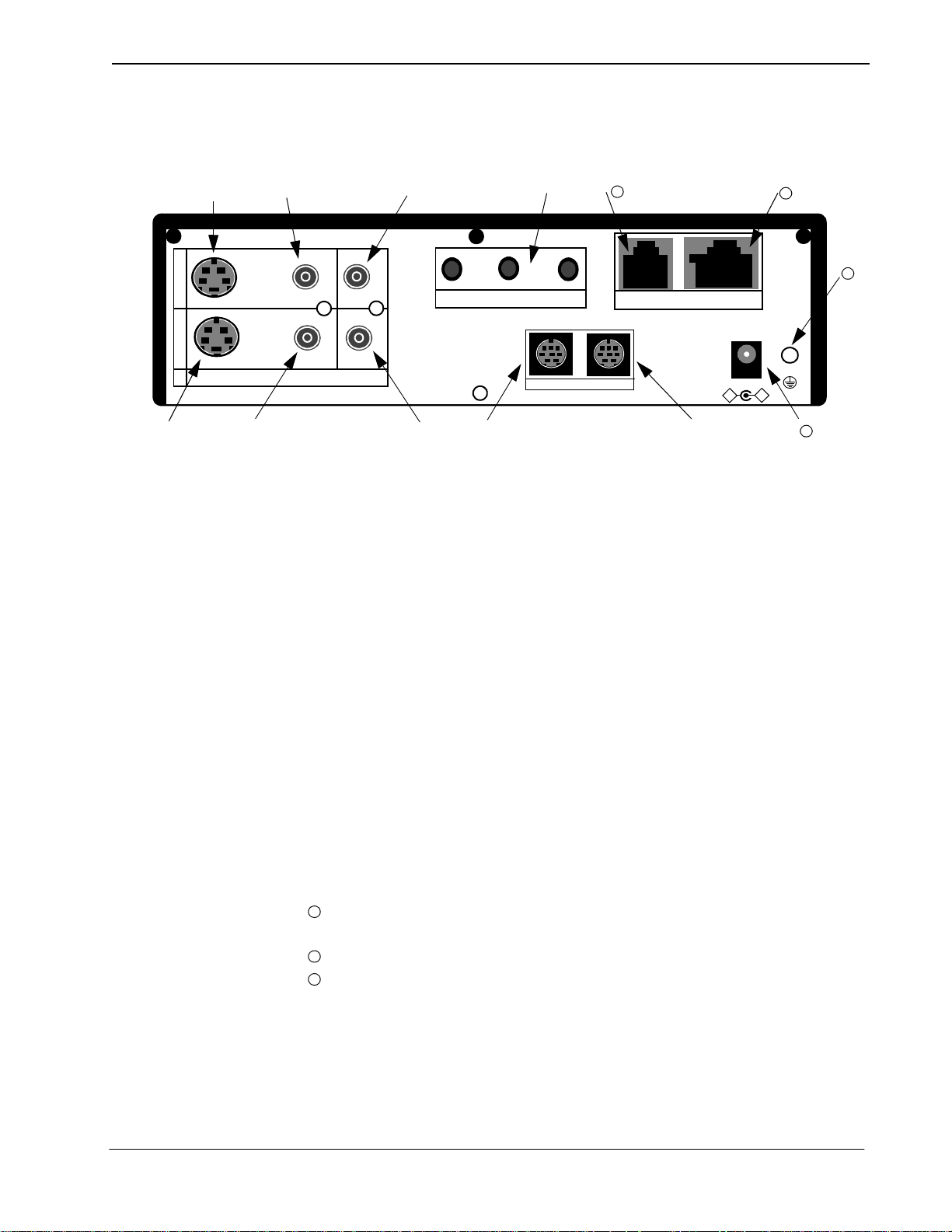
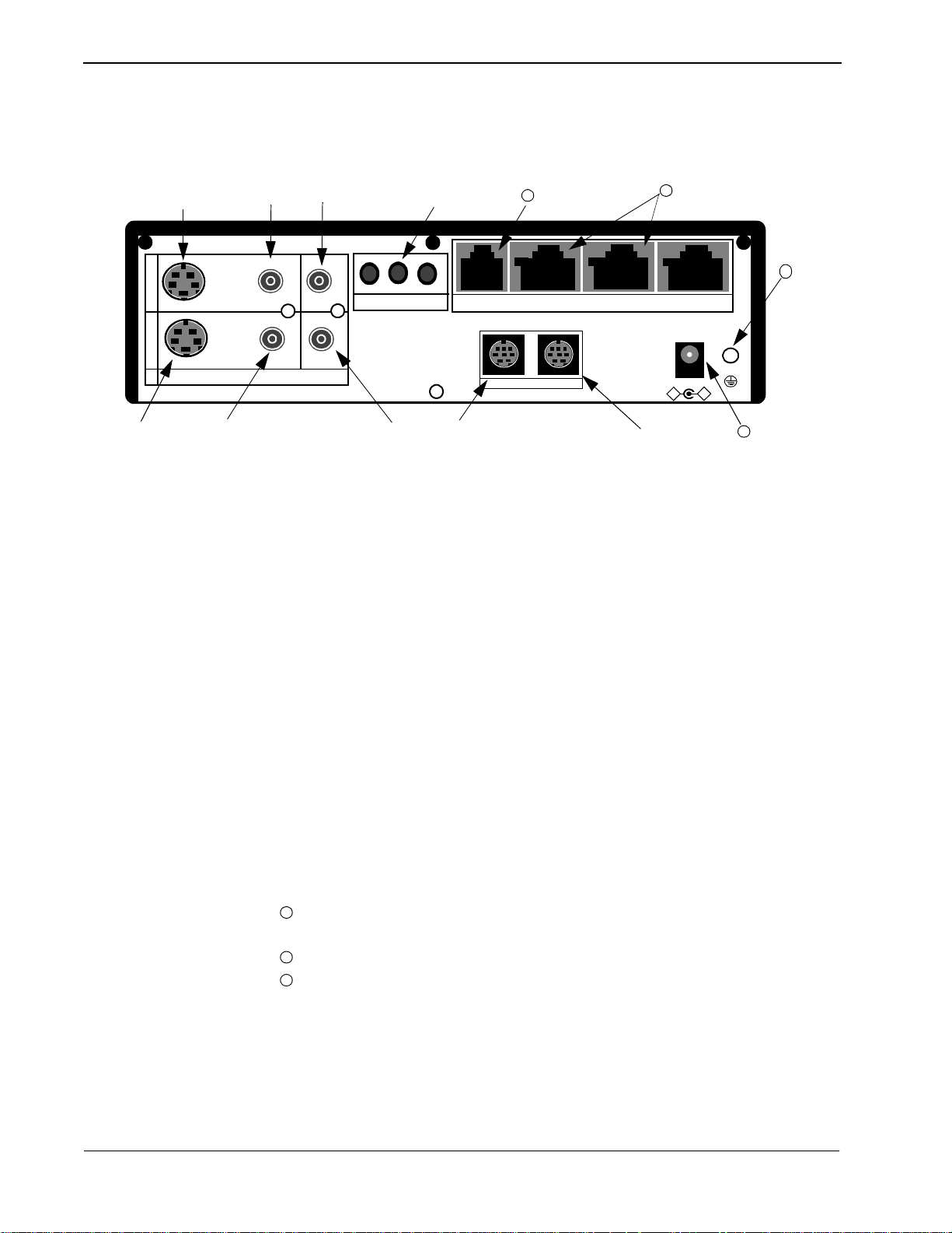
2.3 VisuaLink 128
Rear Panel
Description
➂➃ ➅ ➆
+
O
U
T
I
N
VIDEO2 VIDEO1 AUDIO
①
➁
10
+
+
+
MIC1 MIC2 MIC3
TEL S/T LINE
11
+
+
➈
DC IN 5V
-
+
+
➄
①
VIDEO 2 IN (S-Video input): Provides an S-Video input connection for a
➇
Serial1 Serial2/RMT
camera or other video source.
➁
VIDEO 1 IN (NTSC input): Provides a composite input connection for a
camera or other video source.
➂
VIDEO 2 OUT (S-Video output): Provides an S-Video output connection to
a monitor or other display device.
➃
VIDEO 1 OUT (NTSC output): Provides a composite output connection to a
monitor or other display device.
➄
AUDIO IN: Provides a line level audio input from a VCR, audio mixer , other
audio transmission device or External Echo Canceller connection.
➅
AUDIO OUT (AUX output): Provides a line level audio output to an
amplified speaker, other audio receiver device or External Echo Canceller
connection.
➆
MIC 1~3: Mini stereo phono plugs connection for one to three microphones.
➇
SERIAL 1 (RS232C input): Provides a mini din connection conforming to
RS232 for connection to a PC or other data device.
➈
SERIAL 2/ RMT (RS232C input/output): Provides a mini din connection
comforming to RS232 fo r conn ection to a PC, camera or other RS232 device.
➉
TEL terminal: Provides an RJ11 jack for connecting the VoicePoint or other
two wire tele phone.
11
S/T LINE terminal: Provi des an ISDN BRI S interface us ed to connect to the
communication data line.
12
DC power inp ut terminal: P rovides an AC adapter int erface for AC power.
13
Grounding terminal: Provides a ground connect io n at should be connected t o
earth ground.
13
12
NDA-24230 Issue 2.0 Page 2-3
Chapter 2 VisuaLink 128/384 User Guide
2.4 VisuaLink 384 Rear Panel Description
➂
+
O
U
T
I
N
VIDEO2 VIDEO1 AUDIO
①
➁
➃
➅
➆
10
+
MIC1 MIC2 MIC3
+
+
TEL LINE 1 LINE 2 L INE 3
11
+
+
➈
DC IN 5V
-
+
12
+
➄
①
VIDEO 2 IN (S-Video input): Provides an S-Video input connection for a
Serial1 Serial2/RMT
➇
camera or other video source.
➁
VIDEO 1 IN (NTSC input): Provides a composite input connection for a
camera or other video source.
➂
VIDEO 2 OUT (S-V ideo ou tput): P rovides an S-Video output connection to a
monitor or other display device.
➃
VIDEO 1 OUT (NTSC output): Provides a composite output connection to a
monitor or other display device.
➄
AUDIO IN: Provides a line level a udio i nput f rom a VCR, audio mixer, other
audio transmission device or External Echo Canceller connection.
➅
AUDIO OUT (AUX output): Provides a line level audio output to an
amplified speaker, other audio receiver device or External Echo Canceller
connection.
➆
MIC 1~3: Mini stereo phono plugs connection for one to three microphones.
➇
SERIAL 1 (RS232C input): Provides a mini din connection conforming to
RS232 for connection to a PC or other data device.
➈
SERIAL 2/ RMT (RS232C input/output): Provides a mini din connection
comforming to RS232 for connection to a PC, came ra or other RS232 device.
➉
TEL terminal: Provides an RJ11 jack for connecting the VoicePoint or other
two wire telephone.
11
S/T LINE terminal: Provides three (3) ISDN BRI S interfaces to connect to
the communication data line.
12
DC power input terminal: Provides an AC adapter interface for AC power.
13
Grounding terminal: Provides a ground conne ct ion at should be connect ed t o
earth ground.
13
Page 2-4 NDA-24230 Issue 2.0

VisuaLink 128/384 User Guide Chapter 2
Table 2-1: VisuaLink 128 and VisuaLink 384 General Parameters
Parameter VisuaLink 128 VisuaLink 384
Line
Video
Camera
Connection
Line Type
Transmission
Speed
Interface One RJ-45 Modular Jack Three RJ-45 Modular Jacks
Compression H. 261, H.263 H. 261, H.263
Resolution
Input / Output
Interface
Protcol H/281, NEC video method H/281, NEC video method
Control VCCI, D3O VCCI, D3O
Basic Rate Interface (BRI)
National ISDN-1
•TEL
• 64 Kbps (B)
• 2x64 Kbps (2B)
• Upgradeable to 384 Kbps
Note:
Px56 Kbps mode complies with
B and 2B
• CIF (resolution: 352x288) (H.261)
• QCIF (resolution: 176x144) (H.263)
• Annex D (720x480) still graphic
transmission / reception
• NTSC composite: 1 input, 1 output
(RCA pin jack)
• S-Video component: 1 input, 1 output
(DIN 4-pin)
Basic Rate Interface (BRI)
National ISDN-1
•TEL
• 64 Kbps (B), 2 x 64kbps (2B)
• 128, 192, 256, 320, 384 Kbps
• 56, 112, 168, 224, 280, 336kbps
P x 56kbps mode co mp lie s w i th B an d 2B.
Note:
• CIF (resolution: 352x288) (H.261)
• QCIF (resolution: 176x144) (H.263)
• Annex D (720x480) still graphic
transmission / reception
• NTSC composite: 1 input, 1 ou tpu t (R CA pin
jack)
• S-Video component: 1 input, 1 output (DIN 4-
pin)
Audio
Data
• G.711 (3.4kHz)
Compression
Echo Control 7kHz built-in echo canceller 7kHz built-in echo canceller
Input / Output
Interface
Serial
Control
• G.722 (7kHz)
• G.728 (3.4kHz)
• Line Audio: 1 input, 1 output (RCA pin
jack)
• Headset: 1 input, 1 output (stereo mini
plug)
• Analog phone port: 1 input 1 output (RJ11 modular jack)
• Microphone input port: 3 inputs (mono
mini plug)
• Ports: 2 Serial (DIN 8-pin)
• Speed: 1.2-38.4 Kbps, asynchronous
• Start-Stop synchronization
• PC control
• Camera control
• T/120 data transmission
• Generic data transmission
• G.711 (3.4kHz)
• G.722 (7kHz)
• G.728 (3.4kHz)
• Line Audio: 1 input, 1 output (RCA pin jack)
• Headset: 1 input, 1 output (stereo mini plug)
• Analog phone port: 1 input, 1 output (RJ-11
modular jack)
• Microphone input port: 3 inputs (mono mini
plug)
• Ports: 2 Serial (DIN 8-pin)
• Speed: 1.2-38.4 Kbps, asynchronous
• Start-Stop synchronization
• PC control
• Camera control
• T/120 data transmission
• Generic data transmission
NDA-24230 Issue 2.0 Page 2-5

Chapter 2 VisuaLink 128/384 User Guide
Table 2-1: VisuaLink 128 and VisuaLink 384 General Parameters (continued)
Parameter VisuaLink 128 VisuaLink 384
User Interface
Unit Size
Power
Requirements
Operating
Environment
• Wireless remote control
(built-in IR receiver)
• PC connected (with serial port)
PC software sold separately is required
• Telephone (for analog line, 2-line cable,
RJ-11)
• Dimensions: 10”(W) x 7”(D) x 2.25” (H)
(254 mm x 177 mm x 57 mm)
• Weight: less than 5 lbs. (3 kg.)
Attached external AC adapter:
• Input Voltage: 90-110 VAC, 50-60 Hz
• Output Voltage: +5VDC @ 4.2 A (max)
°
• Temperature: 40°-104° F (5°-40
• Humidity: 20-80%, Non-condensing
C)
• Wireless remote control
(built-in IR receiver)
• PC connected (with serial port)
PC software sold separately is required
• Telephone (for analog line, 2-line cable,
RJ-11)
• Dimensions: 10”(W) x 7”(D) x 2.25” (H)
(254 mm x 177 mm x 57 mm)
• Weight: less than 5 lbs. (3 kg.)
Attached external AC adapter:
• Input Voltage: 90-110 VAC, 50-60 Hz
• Output Voltage: +5VDC @ 4.2 A (max)
• Temperature: 40°-104° F (5°-40° C)
• Humidity: 20-80%, Non-condensing
Page 2-6 NDA-24230 Issue 2.0

VisuaLink 128/384 User Guide Chapter 2
Table 2-2: VisuaLink 128 and VisuaLink 384 External Interface Parameters
Parameter VisuaLink 128 VisuaLink 384
Line Interface
Video 1 In
Video
Input
Video 2 In
Video 1 Out
Video
Output
Video 2 Out
• Applicable Line:
(1) ISDN BRI
(2) High speed digital leased line
• Interface: National ISDN-1
• Connector: 1 Modular jack (RJ-45)
• Transmission speed: 64/56 Kbps B,
2x64/2x56 Kbps 2B
• Standard: NTSC composite signal
(525 line, 59.94Hz)
• Connector: RCA pin jack
• Standard: S-Video Component signal
(525 line, 59.94Hz)
• Connector: DIN 4-pin
• Standard: NTSC composite signal
(525 line, 59.94Hz)
• Connector: RCA pin jack
• Standard: S-Video Component signal
(525 line, 59.94Hz)
• Connector: DIN 4-pin
• Applicable Line:
(1) ISDN BRI
(2) High speed digital leased line
• Interface: National ISDN-1
• Connectors: 3 Modular jacks (RJ-45)
• Transmission speed:
1) 64, 128 192, 256, 320, 384 Kbps
2) 56, 112, 168, 224, 280, 336kbps
• Standard: NTSC composite signal
(525 line, 59.94Hz)
• Connector: RCA pin jack
• Standard: S-Video Component signal
(525 line, 59.94Hz)
• Connector: DIN 4-pin
• Standard: NTSC composite signal
(525 line, 59.94Hz)
• Connector: RCA pin jack
• Standard: S-Video Component signal
(525 line, 59.94Hz)
• Connector: DIN 4-pin
Audio
Input
Line Audio In
Headset Input
Microphone
Input
• Input level: -10dBv
• Excessive Load Level:+3dB (G711,
G728), +9dB (G722)
• Input Impedance: High impedance,
unbalanced
• Connector: RCA pin jack
(Using recommended headset):
• Microphone: Electric condenser type
(power supply voltage +25V)
• Input impedance: High impedance
(Using recommended microphone):
• Number of connections: 3
• Applicable microphone: Electric
condenser type (pow er supply v oltag e +
15V)
• Impedance: Low impedance
• Input level: -10dBv
• Excessive Load Level:+3dB (G711, G728),
+9dB (G722)
• Input Impedance: High impedance,
unbalanced
• Connector: RCA pin jack
(Using recommended headset):
• Microphone: Electric condenser type (power
supply voltage +25V)
• Input impedance: High impedance
(Using recommended microphone):
• Number of connections: 3
• Applicable microphone: Electric condenser
type (power supply voltage + 15V)
• Impedance: Low impedance
NDA-24230 Issue 2.0 Page 2-7

Chapter 2 VisuaLink 128/384 User Guide
Table 2-2: VisuaLink 128 and VisuaLink 384 External Interface Parameters (continued)
Parameter VisuaLink 128 VisuaLink 384
Line Audio
Out
Audio
Output
Headset
Output
Serial 1
Serial
Port
Serial 2 / RMT
Analog Phone
Interface
AC Adapter Interf ac e
• Output level: -10dBv
• Excessive Load Level: +3dB (G711,
G728), +9dB (G722)
• Output Impedance: Low impedance,
unbalanced
• Connector: RCA pin jack
(Using recommended headset):
• Speaker: Dynamic speaker
• Impedance: Low impedance
• Connector: DIN 8-pin
• Communication speed: 1.2~38.4 Kbps,
start stop synchronization
• Connector: DIN 8-pin
• Communication speed: 1.2~38.4 Kbps,
start stop synchronization
• Connecting cable: 2-line cable
• Connector: 6-pin modular jack (RJ-11)
• Voltage: +5VDC
• Polarity: + inside, - outside
• Connector: EIAJ RC-5320A applicable
• Output level: -10dBv
• Excessive Load Level: +3dB (G711, G728),
+9dB (G722)
• Output Impedance: Low impedance,
unbalanced
• Connector: RCA pin jack
(Using recommended headset):
• Speaker: Dynamic speaker
• Impedance: Low impedance
• Connector: DIN 8-pin
• Communication speed: 1.2~38.4 Kbps, start
stop synchronization
• Connector: DIN 8-pin
• Communication speed: 1.2~38.4 Kbps, start
stop synchronization
• Connecting cable: 2-line cable
• Connector: 6-pin modular jack (RJ-11)
• Voltage: +5VDC
• Polarity: + inside, - outside
• Connector: EIAJ RC-5320A applicable
Page 2-8 NDA-24230 Issue 2.0
VisuaLink 128/384 User Guide Chapter 2
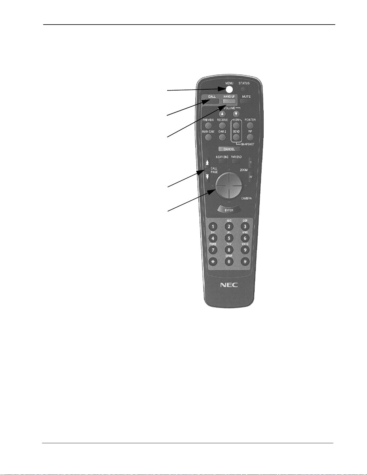
2.5 Remote Controller
2.5.1 Basic Operational Buttons
a
b
c
d
e
From top left to down followed by top right to down.
(a) MENU button
Displays the configuration menus on-screen.
(b) CALL button
Displays the line connection menu.
(c) HANG UP button
Hangs-up the video conference line.
(d) CALL PAGE button
Allows for scrolling of on-screen menus.
(e) CAMERA CONTROL button
Provides Pan/Tilt control of the camera. In addition, provides up down/left/
right control of the cursor when the menu is displayed.
NDA-24230 Issue 2.0 Page 2-9
Chapter 2 VisuaLink 128/384 User Guide
g
h
i
j
f
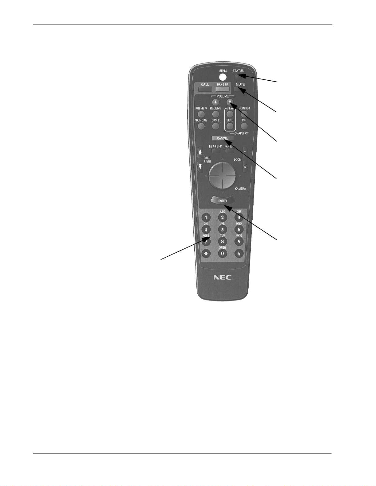
(f) NUMERICAL button
Used to enter preset dialing numbers and camera presets.
(g) STATUS button
Displays local time and conference status on-screen.
(h) MUTE button
Toggles between muting and unmuting the local mics.
(i) VOLUME button
Allows adjustment of the audio output.
(j) CANCEL button
Cancel the last entered using the on-screen menus.
k
(k) ENTER button
Stores a value set by the user.
Page 2-10 NDA-24230 Issue 2.0
VisuaLink 128/384 User Guide Chapter 2
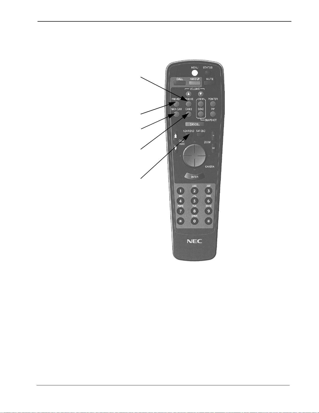
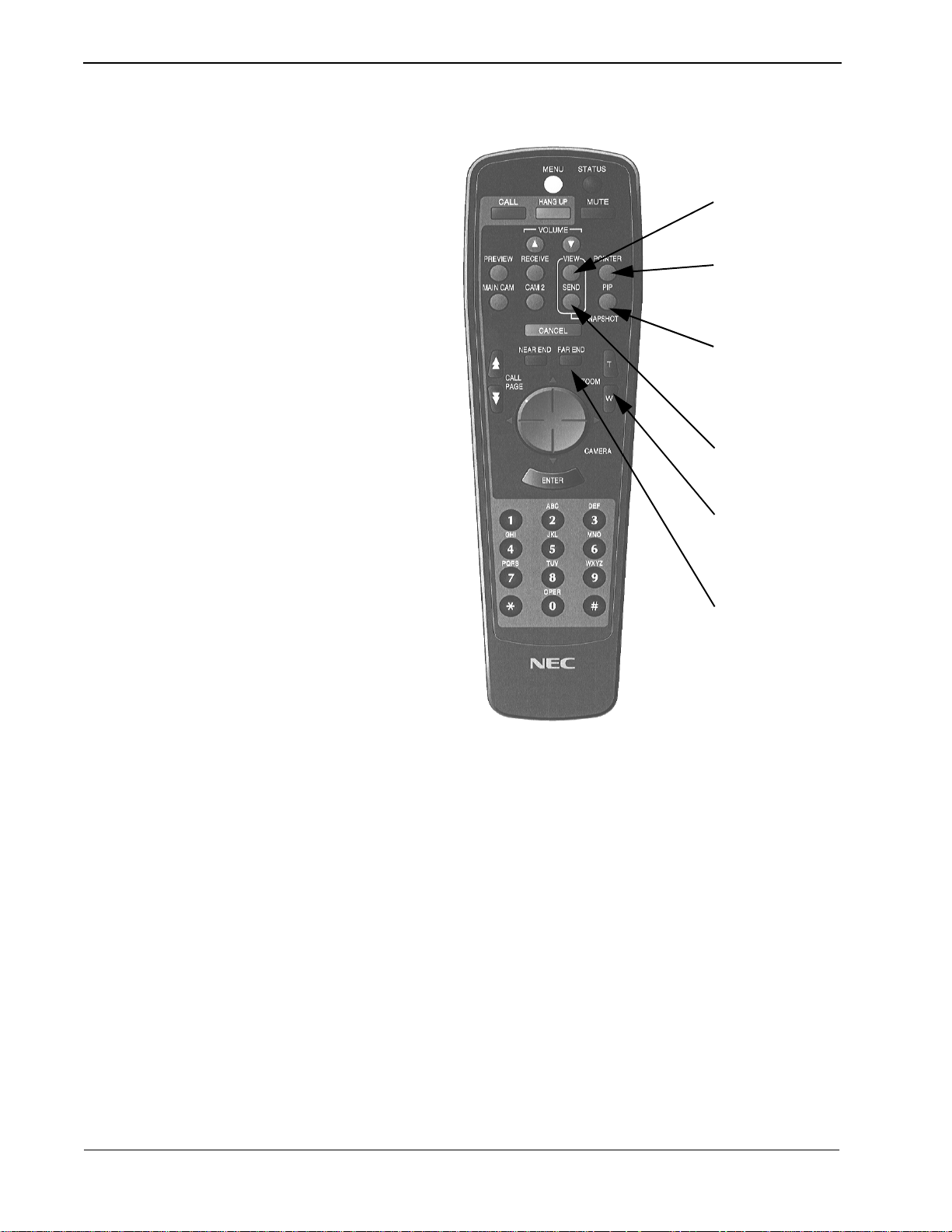
2.5.2 Video Conference, Operational Buttons
1
2
3
4
5
From top left to down followed by top right to down.
1. RECEIVE button
Displays the far-site’s video on-screen.
2. PREVIEW button
Displays the local video on-screen.
3. MAIN CAMERA button
Sends video input #1 image to the far-site.
4. CAMERA 2 button
Sends the video #2 image to the far-site.
5. NEAR END button
Activates local camera control.
NDA-24230 Issue 2.0 Page 2-11
Chapter 2 VisuaLink 128/384 User Guide
6
7
8
9
6. SNAPSHOT VIEW button
Displays the graphic camera image.
7. POINTER button
This turns on and off a pointer display.
8. PIP button
This turns on and off a PIP display.
9. SNAPSHOT SEND button
Sends a graphic image to the far-site.
10
11
10.ZOOM button
Allows for camera control of zoom in/out function.
11.FAR END button
Activates far-site camera control.
Page 2-12 NDA-24230 Issue 2.0
VisuaLink 128/384 User Guide Chapter 3
Chapter 3 Initial Setting and Operation Checking
After completing the external phase, start the initial setting of VisuaLink.
3.1 Preparation
3.2 Turn Power ON or OFF
POWER HEADSET
①
Put the attached two batteries in the attached remote controller.
➁
Turn the VisuaLink and all external equipment power in the ON position.
➂
Position the TV monitor and t he VisuaLink system so that they c an be v iewed.
The VisuaLink can be turned ON or
POWER
Power Switch
Turning on the power:
OFF
by the
Power LED
POWER SWITCH
LINE
B1 B2-B6
on the front.
Press the
powering up, the green LED power lamp and Line B1 and B2-B6 light
simultaneously. While the system is in an initialize state, a blue screen with the
message
VisuaLink has completed its initialization, the message will disappear and be
replaced with a preview video ima ge. In addition the B1 and B2-B6 LEDs wil l be
extinguished.
Note 1:
Note 2:
Turning power OFF:
When the
the power turns
POWER SWITCH
Please wait for a while
Unstable picture and sound may momentarily be output at the start of the
initialization.
If Line B1 B2-B6 LEDs do not extinguish after initialization (about 30
seconds), please turn power
POWER SWITCH
OFF
. The power lamp extinguishes when the power is
on the front of the VisuaLink. While the unit is
will be displayed on the monitor. When the
OFF
and then back to the ON position.
is pressed while the power is in the ON position,
OFF
.
NDA-24230 Issue 2.0 Page 3-1

Chapter 3 VisuaLink 128/384 User Guide
This page is for your notes.
Page 3-2 NDA-24230 Issue 2.0

VisuaLink 128/384 User Guide Chapter 4
Chapter 4 Application Setup
4.1 Guidelines
The following are key points when installing the VisuaLink.
(1) The V is uaLi nk should be installed on a flat surface. It is not recommended
that the unit be installed on its side.
(2) Please allow for 2 inches (6 centi meters) on both sides of the equipment for
ventilation.
(3) Allow the front of the unit to be visible.
The following are the specifications for the IR receiver/transmitter.
(1) The receiver is able to receive an IR signal up to 20 feet (6 meters).
(2) The IR receiver should be able to receive a signal at an angle of 30
degrees
or less from t he left to right.
(3) The IR receiver should be able to receive a signal at an angle of 15 degrees
or less from the top to bottom.
Please place only light objects on the equipment such as a telephone.
NDA-24230 Issue 2.0 Page 4-1
Chapter 4 VisuaLink 128/384 User Guide
4.2 Hardware
The preceeding s ections wil l give step by ste p procedures for the installat ion of the
VisuaLink system in specific applications. Pick the application and follow the
instructions. This section gives a description on how to setup a VisuaLink as a
stand alone.
4.2.1 VisuaLink Standalone
Parts List
No. Name Note
1 VisuaLink 128 or VisuaLink 384 CODEC Engine.
2 Controllable Camera Generic camera to allow for the transmission of video.
3 Microphone Generic microphone to allow for transmission of audio
4 Monitor TV monitor to display local and remote video
Microphone
➂
①
S Interface
U Interface
Monitor
Camera
+
O
U
T
I
N
VIDEO2 VIDEO1 AUDIO
➃
++
+
MIC1 MIC2 MIC3
Serial1 Serial2/RMT
+
➄
TEL S/T LINE
DC IN 5V
-
NT1
➁
+
VisuaLink 128
+
+
➆
AC
➅
AC
Figure 4-1: Connection Diagram for VisuaLink 128
Page 4-2 NDA-24230 Issue 2.0

VisuaLink 128/384 User Guide Chapter 4
U Interface
Monitor
Camera
VisuaLink 384
①
+
O
U
T
I
N
VIDEO2 VI DEO1 AUDIO
++
MIC1 MIC2 M IC3
+
TEL S/T LINE 1 S/T LINE 2 S/T LINE 3
Serial1 S erial2/RMT
+
S Interface
S Interface
S Interface
+
+
DC IN 5V
-
+
NT1
NT1
➁
NT1
➂
Microphone
➃
➄
➅
Figure 4-2: Connection Diagram for VisuaLink 384
An AC adapter has different output voltage and current depending on how it is
used. Please use the power adapter that is shipped with your unit. Also, if
incorrectly connected, it may damage the equipment.
➆
AC
AC
NDA-24230 Issue 2.0 Page 4-3

Chapter 4 VisuaLink 128/384 User Guide
Connection Procedure
①
~ ➆ indicate the procedure numbers.
① Connect the Video Out and the audio of the VisuaLink to the Video
Monitor
Using the attached video cable, plug one side into the connection marked
VIDEO 1 IN
marked
plug one end into the
end into the
Note:
If a Voicepoint is used do not connect the audio output connection.
on the Video Monitor. Plug the other end into the connection
VIDEO OUT
AUDIO OUTPUT
on the VisuaLink. Using the provided audio cable,
AUDIO INPUT 1
of the V ideo Monitor. Plug the other
of the Vi suaLink.
➁ Connect the NT1 device to the VisuaLink.
Using the provided data c able ( RJ45 - RJ45) , plug on e end int o the VisuaLink
connection labeled
ST/LINE
. The other end of the cable, plugs into the NT1
device.
Note:
If the NT1 device is located more than 300 feet (91 meters) away from
the VisuaLink, set the NT1 to have a resistance of 100 Ω. This step
must be repeated three (3) times for a VisuaLink 384. NT1 does not
need to be installed if network terminates in a PBX. In this case
connect
ST/LINE
directly into wall jack.
➂ Connect a microphone to the VisuaLink.
Plug the 3 1/2 mini connector into the VisuaLink connection marked
➃ Connect the Video Camera to the VisuaLink.
Using the provided video cable, plug one end into the connection marked
VIDEO IN
VisuaLink connection labeled
on the D30 camera. Plug the other end of the vi deo cable in to the
VIDEO IN 1
.
➄ Connect the camera control to the VisuaLink.
With a 8 pin minidin to 8 pin minidin, plug one end into the D30 camera
connection marked
connection marked
VISCA IN
SERIAL 1
. Plug the other end into the VisuaLink
.
➅ Connect the camera power.
Plug the Camera AC Power to the AC Power Strip at the bottom of the
cabinet.
➆ Connect the VisuaLink AC Power.
Using the provided AC transformer power cable, plug the power cable into
the V isua Link connecti on marke d
DC-IN-5V
. Plug the other e nd int o t he AC
Power Strip.
MIC1
.
Page 4-4 NDA-24230 Issue 2.0

VisuaLink 128/384 User Guide Chapter 4
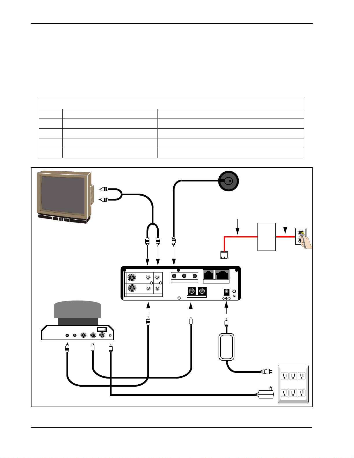
4.2.2 VisuaLink with Voicepoint+
Parts List
No. Name Note
1 VisuaLink 128 or
CODEC Engine.
VisuaLink 384
2 Voice Point+ AEC-50 (option), A generic hands-free phone in the market works OK.
3 Serial Control Camera Generic camera to allow for the transmission of video.
4 TV monitor A generic monitor with a video and audio input.
SU
NT1
Interface
Monitor
Camera
①
+
O
U
T
I
N
VIDEO2 VIDEO1 AUDIO
➁
VoicePoint
+
+
+
MIC1 MIC2 MIC3
Serial1 Serial2/RMT
+
➂
TEL S/T LINE
Interface
➃
+
+
DC IN 5V
-
+
VisuaLink 128
➄
VideoAudio S Video
PC Terminal
MIC
OFF
IN VISCA OUT
ON
Power
➅
➆
AC
Figure 4-3: Connection Diagram for VisuaLink 128
➇
AC POWER
STRIP
➈
AC
NDA-24230 Issue 2.0 Page 4-5

Chapter 4 VisuaLink 128/384 User Guide
U Interface
Monitor
Camera
VideoAudio S Video
S Interface
NT1
VoicePoint
S Interface
NT1
➁
①
➂
+
O
U
T
I
N
VIDEO2 VI DEO1 AUDIO
MIC
OFF
IN VISCA OUT
ON
Power
++
+ +
MIC1 MIC2 M IC3
TEL S/T L INE 1 S/T LINE 2 S/T LINE 3
Serial1 Serial2/RMT
+
➅
S Interface
+
DC IN 5V
-
+
NT1
➃
VisuaLink 384
PC Terminal
➇
AC POWER
STRIP
➄
➆
AC
➈
AC
Figure 4-4: Connection Diagram for VisuaLink 384
An AC adapter has different output voltage and current depending on how it is
used. Please use the power adapter that is shipped with your unit. Also, if
incorrectly connected, it may damage the equipment.
Page 4-6 NDA-24230 Issue 2.0

VisuaLink 128/384 User Guide Chapter 4
Connection Procedure
①
~ ➉ indicate the procedure numbers.
① Connect the Video Out of the VisuaLink to the TV Monitor
Using the attached video cable, plug one side into the connection marked
VIDEO 1 IN
marked
on the TV Monitor. Plug the other end into the connection
VIDEO OUT
on the VisuaLink.
➁ Connect audio from the VisuaLink to the TV Monitor.
Using the provided audio cable, plug one end into the
the TV Monitor. Plug the other end int o the
AUDIO OUTPUT
AUDIO INPUT 1
of the
of
VisuaLink.
Note:
If a Voicepoint is used do not connect the audio output connection.
➂
Connect the Voicepoint to the VisuaLink.
Using the attached RJ11 cable of the Voicepoint, plug the open end into the
VisuaLink connection labeled
TEL
.
④ Connect the NT1 device to the VisuaLink.
Using the provided data c able ( RJ45 - RJ45) , plug on e end int o the VisuaLink
connection labeled
ST/LINE
. The other end of the cable, plugs into the NT1
device.
Note:
If the NT1 device is located more than 300 feet (91 meters) away from
the VisuaLink, set the NT1 to have a resistance of 100 Ω. This step
must be repeated three (3) times for a VisuaLink 384. NT1 does not
need to be installed if network terminates in a PBX. In this case
connect
ST/LINE
directly into wall jack.
➄ Connect the Video Camera to the VisuaLink.
Using the provided video cable, plug one end into the connection marked
VIDEO IN
VisuaLink connection labeled
on the D30 camera. Plug the other end of the vi deo cabl e into t he
VIDEO IN 1
.
⑥ Connect the camera control to the VisuaLink.
With a 8 pin minidin to 8 pin minidin, plug one end into the D30 camera
connection marked
connection marked
VISC IN
SERIAL 1
. Plug the other end into the VisuaLink
.
➆ Connect the camera power.
Plug the Camera AC Power to the AC Power Strip at the bottom of the
cabinet.
➇ Connect a PC to the VisuaLink for data sharing.
Using an 8 pin mini din to DB9 cable, plug the 8 pin end into the VisuaLink
connection marked
NDA-24230 Issue 2.0 Page 4-7
SERIAL 2/RMT
. Plug the other end into the PC.

Chapter 4 VisuaLink 128/384 User Guide
➈ Connect the VisuaLink AC Power.
Using the provided AC transformer power cable, plug the power cable into
the V isu aLink con necti on marked
POWER STRIP
.
DC-IN-5V
. Plug the other end into the
AC
4.2.3 Desktop Configuration Step-by-step procedures for installating the VisuaLink system in a desktop
application.
Equipment to Connect
Parts List
No. Name Note
1 VisuaLink 128 or VisuaLink 384 CODEC Engine.
2 Microphone Generic Microphone to allow for the transmission of
audio.
3 Stand-type Camera Generic camera to allow f or the transmission of video.
4 PC (Provided by customer) Your personal PC with a monitor. PC should have
audio input capability.
5 Video Capture Card Allows for the input of a video image into a PC.
6 Director Software Allows for VisuaLink control via PC. Software may be
downloaded from Web site:
http://www.cng.nec.com/html/products.htm
1. Click on the NTAC icon or select
SUPPORT from the menu bar at the top of the
screen.
2. At the CNG SUPPORT screen, clic k on the NTAC
Online text.
3. At the National Technical Assistance Center
screen, click on the
Downloads
icon or the Downloads text on the
menu bar.
.
Arrow
icon
4. At the Downloads screen, click on the
at the top or bottom of the screen until
▲
you come to
Video-VL128/384
▲
5. Click on the , then click of the VisuaLink
Director for VL128/VL384 text that is highlighted
in blue.
Note:
If you have a problem with this procedure,
please call the NTAC support line at 1-800-852-
4632.
Page 4-8 NDA-24230 Issue 2.0

VisuaLink 128/384 User Guide Chapter 4
Amplified Speakers (Optional)
U
Interface
S
PC Camera
VIDEO DC IN 6V
VisuaLink 128
+
O
U
T
I
N
VIDEO2 VIDEO1 AUDIO
+
+
V
i
d
e
o
+
MIC1 MIC2 MIC3
Serial1 Serial2/RMT
+
A
u
d
i
o
TEL S/ T LINE
-
DC IN 5V
Interface
+
+
+
NT1
Microphone
AC POW ER
STRIP
AC
AC
AC
AC
COM Port 1
COM Port 2
RS-232C
(COM1)
PC Terminal
O
u
O
u
t
t
Video Capture Card
VGA Port
Video In
Audio In
Note1:
PC backpanel may be different than the one shown. Reference the PC manual and Capture card for location of
connectors.
Note 2:
COM 2
of the PC is used for T.120 communication.
COM 1
should connect to the VL
SERIAL PORT 1
.
Figure 4-5: Connection Diagram for VisuaLink 128
NDA-24230 Issue 2.0 Page 4-9

Chapter 4 VisuaLink 128/384 User Guide
AC POW ER
STRIP
PC Camera
VIDEO DC IN 6V
AC
Amplified Speakers (Optional)
VisuaLink 384
+
O
U
T
I
N
VIDEO2 V IDEO1 AUDIO
++
V
i
d
e
o
O
u
t
+ +
MIC1 MIC2 M IC3
+
A
u
d
i
o
O
u
t
S
Interface
TEL S/T L INE 1 S/ T LINE 2 S/T LINE 3
Serial1 Serial2/RMT
-
DC IN 5V
NT1
NT1
NT1
U
Interface
Microphone
+
+
Note 1:
Note 2:
AC
AC
AC
COM Port 1
COM Port 2
Video Capture Card
RS-232C
(COM1)
PC Terminal
Video InAudio In
VGA Port
PC backpanel may be different than the one shown. Reference the PC manual and Capture card for location of
connectors.
COM 2 of the PC is used for T.120 communication. COM 1 should connect to the VL SERIAL PORT 1.
Figure 4-6: Connection Diagram for VisuaLink 384
Page 4-10 NDA-24230 Issue 2.0

VisuaLink 128/384 User Guide Chapter 4
VIDEO
CAMERA
PC
VisuaLink NT1
Connection Procedure for VisuaLink 128 and VisuaLink 384
An AC adapter has different output voltage and current depending on how it is
used. Please use the power adapter that is shipped with your unit. Also, if
incorrectly connected, it may damage the equipment.
1. Install the video capture card into the PC.
Procedure for installing video capture card are included with unit.
2. Position of the VisuaLink on desk top.
Place the VisuaLink on the desk top beside the PC.
3. Position of the PC
Center the PC on the top of the tabl e.
4. Position of the c amera
Center the camera on top or next to the P C monitor. Using the two (2 )
provided Velcro strips, attached the camera to the top of the PC monitor.
5. Position and connect the NT1 device
Position the NT1 to the left of the VisuaLink on the table top. Connect the
cable to the
Note:
NT1 S/T
interface and to the VisuaLink
If the NT1 device is located more than 300 feet (91 meters) away from
ST/LINE
interface.
the VisuaLink, it is best to use the 1 foot (0.3 meter) adapter cable and
set the NT1 to have a resistance of 100Ω. This step must be repeated
three (3) times for a VisuaLink 384. NT1 does not need to be installed
if network terminat es i n a PBX. In this case connec t
WALL JACK
into
.
ST/LINE
6. Connect the audio, video and contro l cables
Locate the cable bundle. The bundle should contain four (4) cables tiewrapped together. Each cable is labeled accor ding to its connector. This label
identifies the cable connection to the proper equipment interfaces.
7. Connect the peripheral equipment to the power strip
The power strip is located on the floor behind the table.
directly
NDA-24230 Issue 2.0 Page 4-11

Chapter 4 VisuaLink 128/384 User Guide
4.2.4 Rollabout Configuration Step by step procedure for installing the VisuaLink system in a turnkey rollabout.
Note:
Connector location on
the monitor may vary.
VIDEO IN
12
S-VIDEO
VIDEO
L
MONO
AUDIO
R
Power Cable Hole
Control,Video,
& Audio Hole
AUDIO OUT
(VAR/FIX)
VHF/UHF
Note:
+
O
U
T
I
N
VIDEO2 VIDEO1 AUDIO
+
O
U
T
I
N
VIDEO2 V IDEO1 AUDIO
CAMERA NO.
1 2 3
AUDIO
VIDEO
MIC
S VIDEO
POWER
OFF ON
IN VISCA OUT
-
+
DC IN
13.5 V
CAMERA REAR
VIDEO IN
12
S-VIDEO
VIDEO
L
MONO
AUDIO
R
AUDIO OUT
(VAR/FIX)
MONITOR REAR
Labeling for the connector may vary.
+ +
++
MIC1 MIC2 MIC3
Serial1 Serial2/RMT
+
TEL S/T LINE
-
DC IN 5V
VisuaLink 128 REAR
+
++
MIC1 MIC2 M IC3
TEL S/T LI NE 1 S/ T LINE 2 S/T LINE 3
Serial1 Serial2/RMT
+
DC IN 5V
-
VisuaLink 384 REAR
+
+
+
+
+
S/T
L-BK LINE PWR
S/T
DIN
INTERFACE
NT1 FRONT
ON
1234
5
POWER
U
NT1 REAR
Figure 4-7: Equipment Placement
Page 4-12 NDA-24230 Issue 2.0

VisuaLink 128/384 User Guide Chapter 4
Powerstrip
Power Switch
4.2.5 VisuaLink System Procedures The following are t he steps and procedures f or the installatio n of the VisuaLink 128
or VisuaLink 384.
STEP ACTION DRAWING
1. Locate and unpack the Cabinet box.
2. Locate Power Strip at bott on-left (looking through
the front) of ca binet and fee d power cable thr ough
the power opening at rear of cabinet.
3. Plug power strip power cable into AC outlet.
Make sure the ON/OFF swi tc h on the upper right
outside of the cabinet is in the OFF position.
Note:
The power switch will be lite when in the
ON position.
NDA-24230 Issue 2.0 Page 4-13

Chapter 4 VisuaLink 128/384 User Guide
STEP ACTION DRAWING
4. Remove Monitor from monitor box.
4a. Place TV monitor on top of cabinet.
5. Locate monitor power cabl e and f eed th rough t he
cable opening at the top of cabinet.
6. From inside the cabinet, plug the monitor power
cable into power strip.
Powerstrip
S-VIDEO
Power Cable
VIDEO IN
12
AUDIO OUT
VIDEO
(VAR/FIX)
L
MONO
AUDIO
R
Page 4-14 NDA-24230 Issue 2.0

VisuaLink 128/384 User Guide Chapter 4
Foam Inserts
Polyethylene
Bag
Packing Carton
V elc ro Strips
IR OUT
Switch
STEP ACTION DRAWING
7. Locate the cable bundle a nd remove from packing
box. The cable bundle contains two (2) 5 in. (12
cm.) Velcro strips. Use these strips to mount the
camera to the top of the monitor.
8. Locate the camera box and remove camera.
9.
Set the IR switch on the Sony D30 camera to the
ON position. The IR switch is located on the
bottom of the Sony D30 camera. This will allow
for the Sony Camera to receive the IR codes from
the VisuaLink remote controller and transmit
them to the VisuaLink Codec for control.
Mount the camera on the t op of monitor , using th e
Velcro strips. Make sure the front of t he camera is
flush with the front of the monitor and th e camera
is centered.
NDA-24230 Issue 2.0 Page 4-15

Chapter 4 VisuaLink 128/384 User Guide
STEP ACTION DRAWING
10. Locate the camera power cable. Plug the camera
power cable into the power strip in cabinet, t hen
feed cable through to p of cabinet and plug into the
Video Power Cable
rear of the camera.
VIDEO IN
12
S-VIDEO
AUDIO OUT
VIDEO
(VAR/FIX)
L
MONO
AUDIO
R
Power
Cable
Hole
11. Locate the VisuaLink 128 or VisuaLink 384 and
remove from packing box.
12. Place the VisuaLi nk 128 or VisuaLink 384 on the
second shelf of the cabinet.
Foam Inserts
Polyethylene
Bag
Pac ki ng C arton
POWER
HEADSET
LINE
POWER
B1 B2
Page 4-16 NDA-24230 Issue 2.0

VisuaLink 128/384 User Guide Chapter 4
Power Plug Connection
+
DC IN 5V
+
-
Serial1 Serial2/RMT
O
U
T
I
N
VIDEO2 VIDEO1 AUDIO
TEL
S/T LINE
MIC1
MIC2
MIC3
VisuaLink 128 Rear
DC IN 5V
+
-
Serial1 Serial2/RMT
O
U
T
I
N
VIDEO2 VIDEO1 AUDIO
TEL S/T LINE 1 S/T LINE 2 S/T LINE 3
MIC1 M IC2 M IC3
VisuaLink 384 Rear
Power Plug Connectio n
VISCA In
12
VIDEO IN
S-VIDEO
VIDEO
AUDIO
L
MONO
R
AUDIO OUT
(VAR/FIX)
Camera Control
Sony D30
Camera Vout
CAMERA
MONITOR
VHF/UHF
Monitor Vin
Monitor Audio L
(Cable)
(Cable)
(Cable)
(Cable)
STEP ACTION DRAWING
13. Locate the VisuaLink 128 or VisuaLink 384
power cable. Plug cable into power strip at
+
+
bottom of cabinet and feed cable through cable
+
slot in rear of second shelf. Plug second end of
power cable into power input at rear of the
VisuaLink 128 or VisuaLink384.
+
+
+
14. The cable bundle is labeled at the ends of the
various connectors. Plug these connectors into
the appropriate devices (camer a/ moni tor ) and
feed down thro ugh openin g at top of cabi net. See
Figure 4-1 and Figure 4-2.
Note:
Connector layout could vary by
manufacture. Please consult their
documentation if connector layout is
different.
+
+
+
+
+
+
+
NDA-24230 Issue 2.0 Page 4-17

Chapter 4 VisuaLink 128/384 User Guide
STEP ACTION DRAWING
15. Inside the cabinet, connect the other ends of the
cable bundle to the VisuaLink 128 or VisuaLink
384. See Figure 4-1 and Figure 4-2.
Video Out
(Cable)
VisuaLink 128 Rear
Audio Output
(Cable)
16. Locate and unpack the microphone and connect
the 3 1/2 inch plug into th e VisuaLink connection
marked MIC1. String the MIC cable out of the
rear of the cabinet. Connect the other end of the
cable into the Microphone and place on table.
+
O
U
T
I
N
VIDEO2 VIDEO1 AUDIO
++
VisuaLink 128/384
Video In
(Cable)
VisuaLink 384 Rear
Video Out
(Cable)
+
O
U
T
I
N
VIDEO2 VIDEO1 AUDIO
+
VisuaLink 128/384
Video In
(Cable)
+
O
U
T
I
N
VIDEO2 VIDEO1 AUDIO
VisuaLink 128 Rear
+ +
MIC1
MIC2
MIC3
Serial1 Serial2/RMT
+
Serial 1
(Cable)
Audio Output
(Cable)
+
+
MIC1 MIC2 MIC3
TEL S/T LI NE 1 S/T LINE 2 S/T LINE 3
Serial1 Serial2/RMT
+
Serial 1
(Cable)
MIC1
+ +
MIC1
MIC2
MIC3
+
Serial1 Serial2/RMT
++
TEL
TEL
S/T LINE
S/T LINE
DC IN 5V
-
-
DC IN 5V
-
DC IN 5V
+
+
+
+
+
+
+
MIC1
+
O
U
T
I
N
VIDEO2 VIDEO1 AUDIO
++
MIC1 MIC2 MIC3
+
TEL S/T LI NE 1 S/T LINE 2 S/T LINE 3
Serial1 Serial2/RMT
+
DC IN 5V
-
+
+
+
VisuaLink 384 Rear
Page 4-18 NDA-24230 Issue 2.0

VisuaLink 128/384 User Guide Chapter 4
Polyethylene
Bag
Foam Inserts
Pac ki ng C arton
123
45
ON
1234
5
ON
POWER
U
NT1 REAR
POWER
HEADSET
POWER
LINE
B1 B2
NT1
VisuaLink 128/384
(one for 128)
(three for 384)
123
45
ON
POWER
U
Power Connection
STEP ACTION DRAWING
17. If an NT1 device has been purchased, locate the
device and unpack.
Note 1:
If an NT1 was not purchased go to Step
23.
Note 2:
Three NT1 are used for the VL384.
18. Locate the dip switch on the rear of the NT1 and
set all to the ON position.
19. Place the NT1 or the three NT1s on the second
shelf, to the right of the VisuaLink 128 or
VisuaLink 384.
20. Locate the NT1 power cable. Plug cable into
power strip at bottom of cabinet and feed cable
through cable slot in rear of second shelf. Plug
second end of power cable into power input at rear
of the NT1.
NDA-24230 Issue 2.0 Page 4-19

Chapter 4 VisuaLink 128/384 User Guide
STEP ACTION DRAWING
21. Locate the network cable (RJ45-RJ45) and
connect one end to the S/T LINE port of the
VisuaLink 128 or VisuaLink 384. Connect the
other end of the network cable into the S/T
interface of the NT1.
Note:
RJ45-RJ45 cable that is included with the
NT1 unit should be used.
+
O
U
T
I
N
VIDEO2 VIDEO1 AUDIO
RJ45 NT1 Cable
+ +
MIC1
MIC2
MIC3
+
Serial1 Serial2/RMT
++
VisuaLink 128 Rear
RJ45 NT1 Cable
TEL
S/T LINE
-
DC IN 5 V
+
+
22. Connect the network cable from the U interf ace
on the NT1 to the network jack provided on the
room wall. Proceed to Step 24.
Note 1:
RJ45-RJ45 cable that is included with the
NT1 unit should be used.
Note 2:
If connecting a VisuaLink 384 system,
Step 21 will have to be re peated three ( 3)
times.
+
O
U
T
I
N
VIDEO2 VI DEO1 AUDIO
ST Interfaces
+
MIC1 MIC2 M IC3
++
+
VisuaLink 384 Rear
NT1 Front
S/T
S/T
L-BK LINE PWR
NT1 Rear
ON
1234
5
POWER
TEL S/T LIN E 1 S/T L INE 2 S/ T LINE 3
DIN
INTERFACE
DC IN 5V
-
Serial1 S erial2/RMT
U
U Interface
+
+
+
Page 4-20 NDA-24230 Issue 2.0

VisuaLink 128/384 User Guide Chapter 4
DC IN 5V
+
-
Serial1 Serial2/RMT
O
U
T
I
N
VIDEO2 VIDEO1 AUDIO
TEL
S/T LINE
MIC1
MIC2
MIC3
RJ45 NT1 Cable
DC IN 5V
+
-
Serial1 Serial2/RMT
O
U
T
I
N
VIDEO2 VI DEO1 AUDIO
TEL S/T LI NE 1 S/T LINE 2 S/T LINE 3
MIC1 MIC2 M IC3
VisuaLink 384 Rear
RJ45 NT1 Cable
VisuaLink 128 Rear
ON/OFF Switch
STEP ACTION DRAWING
23. Locate the network cable (RJ45-RJ45) and
connect one end to the S/T LINE port of the
VisuaLink 128 or VisuaLink 384. Connect the
+
+ +
other end of the network cable into the network
interface provided in the room wall.
Note 1:
If the NT1 or network switch re sides 300
++
+
+
feet (91 meters) or more away from the
VisuaLink 128 or VisuaLink 384, it is
recommend ed that the T ERM switch is
set to ON on the VL128.
Note 2:
In the case a VL384 is being installed, the
network interface card must be take n out
of the system and the appropriate strap
must be set.
Note 3:
If the VL 384 is being installed, Step 23
must be repeated three (3) times.
24. Locate the ON/OFF switch at the upper right
outside of the cabinet. Press the switch to the ON
position.
+
++
+
+
+
+
NDA-24230 Issue 2.0 Page 4-21

Chapter 4 VisuaLink 128/384 User Guide
STEP ACTION DRAWING
25. Verify that all the equipment plugged into the
power strip are turned to the ON position. The
VisuaLink 128, VisuaLink 384, camera and
monitor have their own power switches. If a
device appears to be still in the
OFF
position,
check the power connec tion fr om the Power Strip
to the device. The NT1 does not have a power
switch. The green LED on the front of the NT1 is
an indication the unit is powered ON.
Note:
Make sure the monitor is sel ected for V ideo
1.
26. When the VisuaLink 128 or VisuaLink 384 is
powered ON, a display of the NEC America, Inc
logo, VisuaLink name,
POWERING UP
and
version number will be displayed on the monitor.
America, Inc.
VisuaLink
Powering Up
Ver.22.02.37
POWER
HEADSET
LINE
POWER
B1 B2
Page 4-22 NDA-24230 Issue 2.0

VisuaLink 128/384 User Guide Chapter 4
▲
4.3 Software Setup
When you first turn on your VisuaLink, there will be an initial configuration
screen. These configurati on screens will have to be completed befor e your system
becomes operational.
Start up configuration screens
The following are the startup screens that will be active on first power up or acti-
vated on demand by the user after choosing the Environmental initialize.
Welcome Screen:
This is a welcome screen for the User.
VisuaLink
Thank you for purchasing one of the most
simple and portable video conferencing systems
available.
We will now show you how to set up your system.
This will only have to be done once.
NOTE: If remote controller doesn’t work, make
sure the switch setting of D30 camera IR
out is ON. Switch is located on the
bottom of the camera.
Note is yellow.
Click here to continue
Configure later
NDA-24230 Issue 2.0 Page 4-23

Chapter 4 VisuaLink 128/384 User Guide
▲
▲
Remote Controller Directions:
Gives some general directions for configure the VisuaLink system. Using the
Remote controller highlight the NEXT option to advance to the configure screen
or press the lower portion of the CAMERA CONTROL key to highlight the
Configure Later to advance to the normal ICON screens. If you choose to
configure later, the system will have to be programmed with My numbers and
SPID’s in order to work correctly.
Part 1- Remote Controller Location
- Locate the CAMERA control.
The CAMERA control key is the BLUE round
key. Use this key to move the Cursor
up/down and Left/Right in the Configuration
Screens.
- Locate the ENTER key on the Wireless remote
controller.
Use the ENTER key to confirm selections
and store information.
4.4 Setting Up your ISDN Line Information
Next screen
Prior screen
The following is a description of BRI Line setup
Part 2- Setting up Your ISDN Line
Introduction:
When ordering BRI service , you will usually get
2 My numbers and 2 SPID numbers per BRI.
A SPID normally consists of the user’s 3 digit
area code, 7 digit ISDN telephone number,
followed by a 0101. Ex:
MY Number 1: 9727195854
SPID 1: 97271958540101
Note: The VisuaLink 128 requir es 2 My numbe rs
and 2 SPID #, while the VisuaLink 384
requires 6 My numbers and 6 SPID #.
Next screen
Prior screen
Note is yellow.
Page 4-24 NDA-24230 Issue 2.0

VisuaLink 128/384 User Guide Chapter 4
▲
▲
Video Number 1 Screen’s
Using the number pad of the wireless remote enter My Number with area code
and SPID numbers associated to Line (BRI 1). Each BRI will have My numbers
labeled #1 and #2 and two SPID’s . All four numbers must be entered. Choose
NEXT when complete.
Note:
“PROCEED TO STEP 2” will only be shown on the VisuaLink 128 system.
VisuaLink 384 will show “ Proceed to Line 2 Setup”
Step 1--Enter My Number and SPID for BRI LINE 1
My Number 1:
[]
SPID 1:
[ ]
My Number 2:
[ ]
SPID 2:
[ ]
Next screen
Prior screen
Press ENTER after choosing each item
Step 1--Enter My Number and SPID for BRI LINE 1
My Number 1:
[9727195854]
SPID 1:
[97271958540101]
My Number 2:
[9727195855]
SPID 2:
[ ]
Next screen
Prior screen
Press ENTER after choosing each item
NDA-24230 Issue 2.0 Page 4-25

Chapter 4 VisuaLink 128/384 User Guide
▲
Video Number 2 Screens:
Using the number pad of the wireless remote enter My Number with area code
and SPID numbers associated to Line (BRI 2). Each BRI will have My numbers
labeled #1 and #2 and two SPID’s . All four numbers must be entered. Choose
NEXT when complete.
Note:
This screen will only appear on the VL 384 system.
Step 1--Enter My Number and SPID for BRI LINE 2
My Number 1:
[]
SPID 1:
[ ]
My Number 2:
[ ]
SPID 2:
[ ]
Next screen
Prior screen
Press ENTER after choosing each item
Page 4-26 NDA-24230 Issue 2.0

VisuaLink 128/384 User Guide Chapter 4
▲
▲
Video Number 3 Screens:
Using the number pad of the wireless remote enter My Number with area code
and SPID numbers associated to Line (BRI 3). Each BRI will have My numbers
labeled #1 and #2 and two SPID’s . All four numbers must be entered . Choose
NEXT when complete.
Note:
This screen will only appear on the VL 384 system.
Step 1--Enter My Number and SPID for BR I LINE 3
My Number 1:
[]
SPID 1:
[ ]
My Number 2:
[ ]
SPID 2:
[ ]
4.5 Optional User Settings:
Next screen
Prior screen
Press ENTER after choosing each item
The following is a description for Optional Setting screen.
Part 3 - Optional User Settings
Introduction:
Site Name: Name identification for your
location. Name i s displayed on
far-end monitor when site is viewed.
Password: Required to gain access to the
VisuaLink configuration screens.
Time setting: Sets the internal clock for the
VisuaLink.
Next screen
Prior screen
NDA-24230 Issue 2.0 Page 4-27

Chapter 4 VisuaLink 128/384 User Guide
▲
Optional information:
You may enter this optional information. The name you enter makes it easy for
users to identify this par ticular VisuaLink. The name can be up to 20 characters
long. The Password is the password needed to be entered when selecting the
Utilities ICON. After entering the optional information select the NEXT to
advance to the next screen.
Step 1- Optional User Settings
Your Site Name
[ ]
Password [ ]
Time Setting
[12/1/1998 10:50]
Time Display: <Time only>
Auto Power Save: <OFF>
Next screen
Prior screen
Press ENTER after choosing each item
Application Screen’s
Using the number pad on the wireless remote controller select the application
which the VisuaLink is installed. Your answer to this question will automatically
configure the internal parameters for the following:
Item Rollabout/Other Data Conference Gateway Desktop
Serial Port 1 Camera EVI-D30 T.120 Camera Camera
Serial Port 2 Console Console Console Console
Audio Mode G.722 G.728 G.722 G.722
MLP 4.0 24.0 4.0 4.0
Answer Mode Auto Auto Auto Manual
LSD 1.2 Off 1.2 1.2
Ext. Remote Auto Off Off Off
H.263 Off Off Off Off
Lip Sync On On On On
Page 4-28 NDA-24230 Issue 2.0

VisuaLink 128/384 User Guide Chapter 4
Step 2—Optional User Settings
Key in the number of one of the following
applications.
Applications:
1. Rollabout/Other
2. Data Conference
3. Gateway
4. Desktop
Press CANCEL to page back
Congratulations Screen
Congratulations, you have just finished setting
up your VisuaLink system.
For VisuaLink software updates and general
VisuaLink knowledge, visit the NEC Knowledge
base web site at :
http://www.cng.nec.com
or
http://www.ilibrary .com/ phoe nix /nt ac home.ns f
/homepagenav?opennavigator
- You may begin to use the video conferencing
system immediately.
- Press ENTER to activate your configuration.
Press CANCEL to page back
The VisuaLink is now setup for the configuration you have entered. Press the
ENTER
button on the
REMOTE CONTROLLER
, the V i suaLin k wi ll disp la y a
blue screen and recycle. The Vi suaLink should will power up to a normal state.
You may begin to use the video conferencing system immediately.
Note:
If there are no My Numbers entered in the configuration the VisuaLink
will display the Start Up screens.
NDA-24230 Issue 2.0 Page 4-29

Chapter 4 VisuaLink 128/384 User Guide
Powering Up Screen
America, Inc.
VisuaLink
Powering Up
Ver .22.02.37
Changing the configuration
It is important that the CODEC is set up with a local number and SPID numbers.
If the unit is not setup with a local number (my number) and SPID, the unit will
not allow for dialing and receiving of video calls. If you have entered these
numbers in the Start Up configuration, you may ignore this section. If the
VisuaLink environment has changed, such as the phone number have changed,
you must reconfigures the numbers in the VisuaLink.
Page 4-30 NDA-24230 Issue 2.0

VisuaLink 128/384 User Guide Chapter 5
Chapter 5 System Parameter/Environment Setting
System parameter sets the operation conditions of the VisuaLink 128 or
VisuaLink 384. Environment setting can be set such as camera class, audio
related, data related, line related and local office status. Loopback feature can be
used as a maintenance feature.
5.1 Environment Setting Menu
MENU
Note 1:
Note 2:
Make system parameter changes when the system is not connected.
Depending on the setting for audio, data speed and bit rate, and the video
has the possibi lity for not bei ng tr ansmi tted. Ple ase ref er t o
Audio/Data/V ideo Bit Rate Assig nment Table
audio, data, video bit rate.
5.1.1 Set an environment
①
Press the
MENU
button to display the
▲
for bit rate assignmen t of
MAIN MENU
Appendix A:
.
Setting the PIP parameter.
NDA-24230 Issue 2.0 Page 5-1

Chapter 5 VisuaLink 128/384 User Guide
CAMERA
CONTROL
➁
Move the cursor with the
ENVIRONMENT SETTING
Setting environments.
➂
Press the
ENTER
button.
CAMERA CONTROL
icon.
▲
button to the
ENTER
Please input password.
[ ]
Press ENTER after inputting password.
The system will not operate correctly if the environment setting are incorrect.
Therefore, the system has a password so that only the person in charge of
controlling video co nfere nce can c hange t he set tings . Factory de fault passwor d is
1234
.
Page 5-2 NDA-24230 Issue 2.0

VisuaLink 128/384 User Guide Chapter 5
➃
Enter the pas sword.
CAMERA
CONTROL
ENTER
Please input password.
[****]
Press ENTER after inputting password.
A password consists of 4-digit number. Input characters are displayed in *.
NDA-24230 Issue 2.0 Page 5-3

Chapter 5 VisuaLink 128/384 User Guide
CAMERA
CONTROL
ENTER
➄
Press the
ENTER
button.
When a password is correctly entered: Environment setting menu is
displayed.
▲
Video parameter setting.
You can choose an icon with the
Icon Description
CAMERA CONTROL
Menu icon for setting video
algorithms, video coding, video
priorities, camera control, and video
input selection
Menu icon for setti ng audio algorithms ,
audio delay, audio input/output port
assignments, and voice activated
camera control.
Menu icon for activating dat a speed and
serial control.
Menu icon for setting video speed,
network numbers, and call answer
mode.
Menu icon for setting the site name, my
number, password, and SPIDs.
button.
Menu icon for activating loopbacks,
also allows for the viewing of
hardware, and software rev. levels and
allows for in itializing.
Page 5-4 NDA-24230 Issue 2.0

VisuaLink 128/384 User Guide Chapter 5
CANCEL
5.1.2 When a password is incorrect It goes back to the password-entering screen.
Please input password.
[ ]
Password incorrect.
Press ENTER after inputting password.
Note:
Press the
CANCEL
button to get out of the menu.
NDA-24230 Issue 2.0 Page 5-5

Chapter 5 VisuaLink 128/384 User Guide
5.2 Video Setting
CAMERA
CONTROL
ENTER
This sets video, algorithm, types of camera to be controlled, and video input
selection.
To set video
①
VIDEO SE TT ING
Select
icon in the environment setting menu.
▲
Video parameter setting.
➁
Press
ENTER
button.
Page 5-6 NDA-24230 Issue 2.0

VisuaLink 128/384 User Guide Chapter 5
The setting screen is displayed. The current setting is displayed.
▲
Vide o format : < FCIF>
Video codi ng : < H263 >
CAMERA
CONTROL
ENTER
Video format: Sets the video format. Possible settings are:
Video Coding: Sets the default coding rate. Possible settings are:
Video priority: Sets the default video coding transmiss ion rate. Possible settings
Camera mod: Sets the type of camera to be controlled. Possible settings are:
Video 1 and 2: Operate together. Sets which of the video inputs labeled on the
MUTE function Sets the audio to a mute or sets the audio and video to mute.
Video priority : < Motion >
Camera type : < EVI-D30 >
Video source
VIDEO1 : < Camera1 >
VIDEO2 : < Camera2 >
MUTE function : <Audio and Video>
Press ENTER after choosing.
FCIF:352 x 288 or QCIF:176 x 144
H.261 or H.263
are:
Motion: more of the bandwidth dedicated toward fps.
Resolution: more of the bandwidth dedicated toward resolution.
EVI-D30 or VC-CI
back of the Vis uaLink are to be camera 1 or 2.
Note 1:
Note 2:
➂
Note:
➃
To select an item use the up and down portion of the
CONTROL
button.
To change a setting use the left and right portion of the
CONTROL
ENTER
Press
button to toggle through the item.
button to define it after changing a setting.
After changing a setting, please turn off the power and on again.
Press the
MENU
CANCEL
or
button three (3) times to proceed back to the
CAMERA
CAMERA
video image.
NDA-24230 Issue 2.0 Page 5-7

Chapter 5 VisuaLink 128/384 User Guide
5.3 Audio Setting
CAMERA
CONTROL
ENTER
This icon sets the audio algorithm, audio delay, audio input/output port
assignment, and voice activation camera control.
To set audio:
①
Select audio setting icon in the environment setting menu.
▲
NUMBER
➁
Audio Parameter Setting.
ENTER
Press
button.
Page 5-8 NDA-24230 Issue 2.0

VisuaLink 128/384 User Guide Chapter 5
The setting screen is displayed. The current setting is displayed.
▲
Audio mode : < SB-ADPCM >
Audio delay : < ON >
Audio in/out port : < AUTO >
VCR play : <OFF >
Voice tracking : < ON >
Echo canceller : < ON >
Mute auto answered calls : < No >
Audio level adjustment: CALL PAGE
Press ENTER after choosing.
Audio mode: Sets the default audio coding. Possible settings are:
SB-ADPCM (7kHz, 48 ~ 56kbps), µlaw PCM (3.5kHz,
56kbps), LD-CELP (3.5kHz, 16kbps) or OFF.
Audio delay: Sets the audio transmission/reception delay. This allow
lip sync.
Audio in/out port: Sets the audio in and out port. Possible settings are:
Auto: The VisuaLink determines which output is
connected and input/output from the
appropriate connector.
Line: The input and output audio from the line
level port labeled audio in/out on the back.
Headset: The input and output audio from the headset
connection on the front.
Telephone: The input and output audio from the
telephone connection on the back.
VCR play: Sets the audio input port to receive a VCR audio signal.
Voice tracking: Sets the voice activated presets on or off.
Echo canceller: Sets the echo canceller to in ternal or external mode.
Mute auto answered
calls:
Note 1:
To select an item use the up and down portion of the
CONTROL
Sets the audio to be mute or unmute at the start of
communication in an automatic answer mode.
CAMERA
button.
Note 2:
NDA-24230 Issue 2.0 Page 5-9
To change a setting use the left and right portion of the
CONTROL
button to toggle through the item.
CAMERA

Chapter 5 VisuaLink 128/384 User Guide
➂
Press the
[dB]
Sets the default volume
setting
Allows for activating or
deactivating audio tone
Camera audio preset level
Setting 0 1 2 3 4 5 6 7
dB [level] -36 -33 -30 -27 -24 -21 -18 -15
SEND:
RECEIVE:
MIC/headset gain : <04>
Audio/TEL gain : <00>
Volume:<08> Operation:
Test Tone : <ST OP> Training:
Camera Moving
Level: <3> Condition: _ _ _
Previous page: CALL PAGE
Please select an item and adjust with <–>.
CALLPAGE
-36 -30 -24 -18 -1 2 -6 0 +6
button to proceed to the
AUDIO LEVEL PAGE
Level bar for incoming and
outgoing audio
Sets the outgoing audio
level for the headset and
MIC
Sets the outgoing audio
level for the telephone and
audio input
Status message for audio
test tone
Status bar for the
microphone:
2 3
1
MIC1 MIC2 MIC3
.
➃
➄
ENTER
Press
Press the
video image.
button to define it after changing a setting.
MENU
CANCEL
or
button three (3) times to proceed back to the
Page 5-10 NDA-24230 Issue 2.0

VisuaLink 128/384 User Guide Chapter 5
▲
Data Parameter Setting
5.4 Data Setting
CAMERA
CONTROL
ENTER
NUMBER
This icon sets the data speed and serial configurations.
To set data speed:
①
Select data setting icon in the environment setting menu.
➁
Press
ENTER
button.
NDA-24230 Issue 2.0 Page 5-11

Chapter 5 VisuaLink 128/384 User Guide
The setting screen is displayed. The current setting is displayed.
▲
MLP Speed : < 4.0kb/s >
LSD speed : < 1.2kb/s >
Serial port setting
Port 1 : < Camera >
Port 2 : < Console >
User port speed : < 9.6kb/s >
T120 port speed : < 38.4kb/s >
Console speed : < 9.6kb/s >
Console parity : < 8 bit none >
Press ENTER after choosing.
MLP: Multi Layer data sets the speed for NEC far-end control.
Note:
MLP must be active i n order to upgra de VL syst em
on-line.
LSD: Low Speed data sets the speed for far-e nd camera con trol .
Serial port setting: Sets the type of control to be activated on the serial port.
User port speed: Sets the data transmission rate for a point-to-point
environment.
T120 port speed: Sets the data transmission rate for a multipoint
environment.
Console speed: Sets the baud speed for a terminal which might be
connected to the VisuaLink serial port.
Console parity: Sets the parity and data lengt h for a t ermina l which mi ght
be connected to the VisuaLink serial port.
Note 1:
Note 2:
Note 3:
➂
Press
To select an item use the up and down portion of the
CONTROL
button.
To change a setting use the left and right portion of the
CONTROL
button to toggle through the item.
Appendix A is a table detailing MLP to LSD speed setting relationship.
ENTER
button to define after changing a setting.
CAMERA
CAMERA
➃
Press the
MENU
and
CANCEL
button three (3) t im es to proceed back to the
video image.
Page 5-12 NDA-24230 Issue 2.0

VisuaLink 128/384 User Guide Chapter 5
▲
Network Parameter Setting.
5.5 Communication Setting
CAMERA
CONTROL
ENTER
NUMBER
This icon sets the video speed, network type, and answer mode.
To set communication:
①
Select communication setting icon in the environment setting menu.
➁
Press
ENTER
button.
NDA-24230 Issue 2.0 Page 5-13

Chapter 5 VisuaLink 128/384 User Guide
The setting screen is displayed. The current setting is displayed.
▲
Speed : < 128Kb/s >
Incoming mode : < Select >
Number of rings : <1>
Restricted dial No. : [2222]
Call restriction : < No limit >
Register speed dial : < Allowed >
Press ENTER after choosing.
Speed: Sets the default transmission rate. What ever rate is set,
this is the rate shown in the dialing screen.
Incoming mode: Sets the incoming call mode. Posible settings are:
Auto - automatically answers the call.
Manual - the user must answer the call with t he remote.
Select - Only answers calls that are stored in the speed
dial.
Number of rings: The number of rings required before the system answers
the call.
Restricted dial No.: Allows the user to set caller restriction number.
Call restriction: Allows the user to set a call restriction. Possible settings
are:
No limit - the user can place calls with no restrictions.
Speed dial only - the user can only place calls that are
stored in the speed dial register.
Manual dial inhibited - the user cannot place manual
calls.
Register speed dial: Allows the user to set access level for speed dial
registrations. Possible settings are:
Allowed - allows the user the access to set speed dial.
Disabled - the user is not allowed to access th e speed dial
registration.
Note 1:
Note 2:
To select an item use the up and down portion of the
CONTROL
button.
To change a setting use the left and right portion of the
CONTROL
button to toggle through the item.
CAMERA
CAMERA
➂
➃
ENTER
Press
Press the
button to define it after changing a setting.
MENU
CANCEL
or
button three (3) times to proceed back to the
video image.
Page 5-14 NDA-24230 Issue 2.0

VisuaLink 128/384 User Guide Chapter 5
▲
Local Site Setting.
5.6 Local Setting
CAMERA
CONTROL
ENTER
This icon sets the site name, my number, password, and SPIDs.
5.6.1 Display the
①
LOCAL SETTING
Select
LOCAL SETTING
icon in the
screen
ENVIRONMENT SETTING
menu.
➁
Press
ENTER
button.
The setting screen (location and others) is displayed. The current setting is
displayed.
Note 1:
Note 2:
Note 3:
To select an item use the top and bottom portion of the
CONTROL
To enter a number use the
button.
NUMBER
buttons on the handheld remote.
After entering the site tepehone numbers, move cursor to
press the
ENTER
button. If you are setting up a VisuaLink 128, go to
CAMERA
NEXT
Step 4.
and
NDA-24230 Issue 2.0 Page 5-15

Chapter 5 VisuaLink 128/384 User Guide
Step 1. VL 128/384
Step 1 -Enter Video Number and SPID for Line 1
My Number1
[9727190320_ ]
SPID1
[97271903200101_ ]
My Number2
[972719032_ ]
CAMERA
CONTROL
SPID2
▲
[ ]
NUMBERS
Next screen
Prior screen
Press ENTER after choosing each item.
Move the cursor to the
CAMERA CONTROL
NEXT SCREEN
button.
using the top or bottom portion of the
Step 1 -Enter Video Number and SPID for Line 1
My Number1
[9727190320_ ]
SPID1
[97271903200101_ ]
My Number2
[972719032_ ]
SPID2
[9727190321010_ ]
▲
Next screen
Prior screen
Press ENTER after choosing each item.
Note:
Page 5-16 NDA-24230 Issue 2.0
If you are setting up a VisuaLink 128, go to Step 4.

VisuaLink 128/384 User Guide Chapter 5
Step 2. VL 384
Step 2 - Enter Video Number and SPID for Line 2
My Number1
[9727190322_ ]
SPID1
[97271903220101_ ]
My Number2
[9727190323_ ]
CAMERA
CONTROL
SPID2
▲
[ ]
NUMBERS
Next screen
Prior screen
Press ENTER after choosing each item.
Move the cursor to the
CAMERA CONTROL
NEXT SCREEN
button.
using the top or bottom portion of the
Step 2 - Enter Video Number and SPID for Line 2
My Number1
[9727190322_ ]
SPID1
[97271903220101_ ]
My Number2
[9727190323_ ]
SPID2
[97271903230101_ ]
▲
Next screen
Prior screen
Press ENTER after choosing each item.
NDA-24230 Issue 2.0 Page 5-17

Chapter 5 VisuaLink 128/384 User Guide
Step 3. VL 384
Step 3 - Enter Video Number and SPID for Line 3
My Number1
[9727190324_ ]
SPID1
[97271903240101_ ]
My Number2
[9727190324_ ]
CAMERA
CONTROL
SPID2
▲
[ ]
NUMBERS
Next screen
Prior screen
Press ENTER after choosing each item.
Move the cursor to the
CAMERA CONTROL
NEXT SCREEN
button.
using the top or bottom portion of the
Step 3 - Enter Video Number and SPID for Line 3
My Number1
[9727190324_ ]
SPID1
[97271903240101_ ]
My Number2
[9727190324_ ]
SPID2
[97271903240101_ ]
▲
Next screen
Prior screen
Press ENTER after choosing each item.
Page 5-18 NDA-24230 Issue 2.0

VisuaLink 128/384 User Guide Chapter 5
Step 4. VL 128/384
Step 1 - Optional User Settings
Your Site name
▲
[Irving ]
Password [1234]
Time setting
[12/1/1998 12 : 07]
Time display: <Time Only>
CAMERA
CONTROL
Auto Power Save: < OFF>
NUMBERS
CANCEL
CAMERA
CONTROL
ENTER
Next screen
Prior screen
Press ENTER after choosing each item.
➂
To set the site name, press the
ENTER
Step 5. VL 128/384
This is Remote Name Registration. Using the
cursor to hihlight and Press ENTER to select.
Site name: [IRVING_]
! " # % & ’ ( ) * + . / 0 1 2 3 4 5
6 7 8 9 : ; < = > ? @ A B C D E F G H I J K
L M N O P Q R S T U V W X Y Z [ ¥ ] ^ _ ‘ a
b c d e f g h i j k l m n o p q r s t u v w
x y z { | } ~
Complete
Cancel
button.
Note:
Move the cursor to the character you want to input using the left and right
sides of the
If incorrectly entered, delete the letter wit h the
NDA-24230 Issue 2.0 Page 5-19
CAMERA CONTROL
button and press the
CANCEL
ENTER
button.
button.

Chapter 5 VisuaLink 128/384 User Guide
➃
When complete, use the top and bottom portion of the
CONTROL
button to select
COMPLETE
or
optional information screen.
Step 1 - Optional User Settings
Your Site name
▲
[Irving ]
Password [1234]
Time setting
[12/1/1998 12 : 07]
Time display: <Time Only>
Auto Power Save: < OFF>
Next screen
Prior screen
Press ENTER after choosing each item.
CAMERA
CANCEL
. You return to the
Page 5-20 NDA-24230 Issue 2.0

VisuaLink 128/384 User Guide Chapter 5
5.6.2 Change the password
①
Select the password mo vin g the cursor using the top and/or bottom portion of
CAMERA CONTROL
the
button.
Step 1 - Optional User Settings
Your Site name
[Irving ]
▲
Password [1234]
Time setting
[12/1/1998 12 : 07]
CAMERA
CONTROL
Time display: <Time Only>
Auto Power Save: < OFF>
ENTER
ENTER
NUMBER
Next screen
Prior screen
Press ENTER after choosing each item.
➁
Press the
ENTER
button to set password.
Password [1234]
Input 4-digit password.
Delete digit: CANCEL/ Register digit: ENTER
➂
Enter a 4-d igit password with
NUMBER
button.
Note:
If no number is entered, the password protect will be deactivated.
NDA-24230 Issue 2.0 Page 5-21

Chapter 5 VisuaLink 128/384 User Guide
➃
Register with the
ENTER
button after completing password. You return to
the optional user settings screen.
Step 1 - Optional User Settings
Your Site name
[Irving ]
▲
Password [1234]
Time setting
[12/1/1998 12 : 07]
Time display: <Time Only>
Auto Power Save: < OFF>
Next screen
Prior screen
Press ENTER after choosing each item.
Page 5-22 NDA-24230 Issue 2.0

VisuaLink 128/384 User Guide Chapter 5
5.6.3 Set the date and time
CAMERA
CONTROL
ENTER
①
Move the cursor to the
CAMERA CONTROL
the
TIME SETTING
button.
Step 1 - Optional User Settings
Your Site name
[Irving ]
Password [1234]
▲
Time setting
[12/1/1998 12 : 07]
Time display: <Time Only>
Auto Power Save: < OFF>
Next screen
Prior screen
Press ENTER after choosing each item.
➁
Press the
ENTER
button to de fine the time a nd date setting.
using the top or bottom portion of
ENTER
NUMBERS
12/ 01/ 98
12 : 48
Press ENTER after setting date and time .
➂
Enter date and time with
NUMBER
button.
NDA-24230 Issue 2.0 Page 5-23

Chapter 5 VisuaLink 128/384 User Guide
➃
Register with the
ENTER
button. You return to the optional user settings
screen.
Step 1 - Optional User Settings
Your Site name
[Irving ]
Password [1234]
▲
Time setting
[12/1/1998 12 : 07]
Time display: <Time Only>
Auto Power Save: < OFF>
Next screen
Prior screen
Press ENTER after choosing each item.
Page 5-24 NDA-24230 Issue 2.0

VisuaLink 128/384 User Guide Chapter 5
5.6.4 Set the date and time display
CAMERA
CONTROL
ENTER
①
Move the cursor to the
CAMERA CONTROL
the
TIME DISPLAY
button.
Step 1 - Optional User Settings
Your Site name
[Irving ]
Password [1234]
Time setting
[12/1/1998 12 : 07]
▲
Time display: <Time Only>
Auto Power Save: < OFF>
Next screen
Prior screen
Press ENTER after choosing each item.
➁
Using the right or left portion of the
between
OFF, TIME ONLY
CAMERA CONTROL
DATE+TIME
and
using the top or bottom portion of
button to toggle
for the
TIME DISPLAY
.
➂
Register with the
ENTER
button. You return to the optional user settings
screen.
Step 1 - Optional User Settings
Your Site name
[Irving ]
Password [1234]
▲
Time setting
[12/1/1998 12 : 07]
Time display: <Time Only>
Auto Power Save: < OFF>
Next screen
Prior screen
Press ENTER after choosing each item.
NDA-24230 Issue 2.0 Page 5-25

Chapter 5 VisuaLink 128/384 User Guide
5.6.5 Set the auto power save
CAMERA
CONTROL
ENTER
①
Move the cursor to the
portion of the
CAMERA CONTROL
AUTO POWER SAVE
Step 1 - Optional User Settings
Your Site name
[Irving ]
Password [1234]
Time setting
[12/1/1998 12 : 07]
Time display: <Time Only>
▲
Auto Power Save: < OFF>
Next screen
Prior screen
Press ENTER after choosing each item.
➁
Using the right or left portion of the
between
10min
OFF, 1min, 2min, 3min, 4min, 5min, 6min, 7min, 8min, 9min
for the
AUTO POWER SAVE
using the top or bottom
button.
CAMERA CONTROL
.
button to toggle
and
➂
Register with the
ENTER
button. You return to the optional user settings
screen.
Step 1 - Optional User Settings
Your Site name
[Irving ]
Password [1234]
Time setting
[12/1/1998 12 : 07]
Time display: <Time Only>
▲
Auto Power Save: < OFF>
Next screen
Prior screen
Press ENTER after choosing each item.
Page 5-26 NDA-24230 Issue 2.0

VisuaLink 128/384 User Guide Chapter 5
➃
Move the cursor to the
CAMERA CONTROL
the
NEXT SCREEN
button.
Step 1 - Optional User Settings
Your Site name
[Irving ]
Password [1234]
Time setting
[12/1/1998 12 : 07]
Time display: <Time Only>
Auto Power Save: < OFF>
▲
Next screen
Prior screen
Press ENTER after choosing each item.
using the top or bottom portion of
You must shut down and restart your unit
before the new setting will take effect.
Do you want to restart your unit now?
Yes: ENTER No: CANCEL
➄
ENTER
Press
CANCEL
to restart the system, start up screen will be displayed. Press
to return to
LOCAL SITE SETTING
menu.
NDA-24230 Issue 2.0 Page 5-27

Chapter 5 VisuaLink 128/384 User Guide
America, Inc.
VisuaLink
Powering Up
Ver .22.02.37
Page 5-28 NDA-24230 Issue 2.0

VisuaLink 128/384 User Guide Chapter 5
▲
Maintenance.
5.7 Maintenance Settings
CALL PAGE
CAMERA
CONTROL
ENTER
This sets the loopback test, viewing of hardware/software revision levels and
initializing of the VisuaLink.
To set the maintenance functions.
①
Select the
MAINTENANCE
icon in the Environment Setting menu.
➁
Press
ENTER
button.
The current setting screen is displayed.
Software version 22 . 02 . 37
Hardware version 12 . 00 . 00
▲
Loopback test : < OFF >
Next page: CALL PAGE
Press ENTER after choosing.
Status display for
software and hardware
revisions
Loopback test setting
NDA-24230 Issue 2.0 Page 5-29

Chapter 5 VisuaLink 128/384 User Guide
➂
Press the
CALL PAGE
button to advance to the Initiali ze scr een.
▲
Environment setting initialization
Clear custom register: <Speed dial>
Previous page: CALL PAGE
Press ENTER after choosing.
Note:
Clear custom register options are: All, Speed dial, Redial, and Camera
Preset.
➃
Using the
initialization and press the
Note:
Environment setting initialization allows the user to select preconfigured
CAMERA CONTROL
ENTER
button highlight the appropriate
button.
settings.
Applications
1. Rollabout/Other
2. Data Conference
3. Gateway
4. Desktop
Input application number.
Press CANCEL to page back.
SETTINGS ROLLABOUT/
OTHERS
Serial 1 Camera Camera T120 Camera
Serial 2 Console Console Console Console
MLP 4.0 4.0 24.0 4.0
LSD 1.2 1.2 OFF 1.2
Audio Mode G.722 G.722 G.728 G.722
Ent. Remote
Controller
H.263 OFF OFF OFF OFF
Motion/Resolution Motion Motion Motion Motion
LIP Sync ON ON ON ON
Answer Mode Auto Manual Manual Auto
Auto OFF OFF OFF
Note:
Custom setting initializes the entire VisuaLink. When you pow er the
DESKTOP DATA
CONFERENCE
GATEWAY
VisuaLink OFF and back ON, the start up configuration menu will appear.
Page 5-30 NDA-24230 Issue 2.0

VisuaLink 128/384 User Guide Chapter 5
➄
Using the
The restart screen appears.
Yes: ENTER No: CANCEL
➄
Press
CANCEL
NUMBERICAL
You must shut down and restart your unit
before the new setting will take effect.
Do you want to restart your unit now?
ENTER
to restart the system, start up screen will be displayed. Press
to return to
LOCAL SITE SETTING
buttons to choose the appropriate initialization.
menu.
America, Inc.
VisuaLink
Powering Up
Ver .22.02.37
➅
VisuaLink Start up screen.
NDA-24230 Issue 2.0 Page 5-31

Chapter 5 VisuaLink 128/384 User Guide
This page is for your notes.
Page 5-32 NDA-24230 Issue 2.0

VisuaLink 128/384 User Guide Chapter 6
Chapter 6 About Calling
In this chapter you will learn to make and receive calls. The Dialing Directory is
a phone book that you cre ate, listing t he names and phon e numbers of the sites that
you can call. Once you have entered these names and numbers into the Dialing
Directory , you can call a site by eithe r Directory diali ng or speed dialing. The final
section is how to receive a call on your VisuaLink.
6.1 Place a Manual Call
CALL
You can manually dial a call by pressing the buttons on the handheld remote the
same way you dial a telephone.
①
To manually dial a call, press the
Note:
With video calls, you may have to enter two (2) telephone numbers instead
CALL
button.
of one due to the ISDN BRI network connections often consist of two (2)
lines within one ISDN cable.
▲
Place Manual Dial Call
Place Redial Call
001.
002.
003.
004.
005.
Press ENTER after choosing
▲
➁
Make sure the is pointing at
ENTER
NDA-24230 Issue 2.0 Page 6-1
button.
PLACE MANUAL DIAL CALL
. Press the

Chapter 6 VisuaLink 128/384 User Guide
Place Manual Dial Call
Phone Number 1
ENTER
NUMBER
▲
[ ]
Phone Number 2
[ ]
Speed : <128kb/s>
Press ENTER or CALL after entering
Press CANCEL to go to Call Screen
Checking Operation
Verify that local and remote si tes are able to be se en and heard at the remote e nds.
Verify that a control from the remote controller is normal by referring to
Chapter 8 Operation Method
.
If unable to connect to the remote site it maybe because the remote site is busy,
wait and then repeat the above operation. If the operation persist, proceed to
Chapter 9 Troubleshooting
➂
Enter the first telephone number using the
Note 1:
When pressing down side on
first number is completed, the number is copied to
.
NUMBER
CAMERA CONTROL
buttons,.
button after the
PHONE NUMBER 2
This is done because typically when dialing two (2) BRI numbers, the
PHONE NUMBER 2
number sometimes exactly match or is similar to
the first nu mber.
Note 2:
At any time you may press the
CALL
button and
ENTER
button. This
will immediately place a video call to the far-end.
.
Page 6-2 NDA-24230 Issue 2.0

VisuaLink 128/384 User Guide Chapter 6
Place Manual Dial Call
Phone Number 1
ENTER
NUMBER
➃
If your call needs two (2) telephone numbers, enter the second number using
NUMBER
the
buttons. Press the
[ 9725185000 ]
Phone Number 2
▲
[ 9725185000 ]
Speed : <128kb/s>
Press ENTER or CALL after entering
Press CANCEL to go to Call Screen
ENTER
button when finished . If your call
needs only one (1) telephone number, skip this step.
CAMERA
CONTROL
ENTER
NUMBER
Note:
Two (2) call numbers are only needed when placing a 112/128 kbps call.
All other speeds only require one (1) telephone number.
Place Manual Dial Call
Phone Number 1
[ 9725185000 ]
Phone Number 2
▲
[ 9725185001 ]
Speed : <128kb/s>
Press ENTER or CALL after entering
Press CANCEL to go to Call Screen
➄
Press the
the
CAMERA CONTROL
CAMERA CONTROL
button and the
SPEED
is chosen. Using
button, press the left or right side to scroll
through the speeds until the appropriate speed is found.
NDA-24230 Issue 2.0 Page 6-3

Chapter 6 VisuaLink 128/384 User Guide
Place Manual Dial Call
Phone Number 1
CAMERA
CONTROL
ENTER
NUMBER
[ 9725185000 ]
Phone Number 2
[ 9725185001 ]
▲
Speed : <128kb/s>
Press ENTER or CALL after entering
Press CANCEL to go to Call Screen
CALL
➅
Press the
ENTER
SPEED
TEL, 56, 64 1
112, 128
168, 192 1 (VL384)
224, 256 1 (VL384)
280, 384 1 (VL384)
button or
CALL
PHONE NUMBERS NEED
TO BE ENTERED
2 (VL128)
1 or 2 (VL384)
button to start dialing the remote site.
Calling Remote Site. Please wait…
Phone Number 1
[ 9725185000 ]
Phone Number 2
[ 9725185001 ]
ENTER
Once the line has been conne cted, the screen will automatica lly display th e remote
site.
Page 6-4 NDA-24230 Issue 2.0

VisuaLink 128/384 User Guide Chapter 6
Receiving Video
from Remot e Site
Connected Line Speed: 128kb/s
REC
After the lines connect a picture from the far-site appears.
NDA-24230 Issue 2.0 Page 6-5

Chapter 6 VisuaLink 128/384 User Guide
6.2 Set Speed Dial Number
MENU
The Dialing Directory is a phone book that you create, listing the names and
phone numbers of the remot e site s. It makes dia ling call s fas ter an d easier. When
you add a new directory entry, you enter the site name and the phone number.
When you add an entry, the speed dial directory assigns a speed dial number for
that site. The next ti me you want to ca ll that s ite, you can si mply type in the speed
number or highlight the site name.
6.2.1 Adding a new entry in the Speed Dial Bin
①
Press the
MENU
button to display the on-screen icons.
▲
CAMERA
CONTROL
ENTER
Setting the PIP parameter.
➁
Highlight the icon for Registering the Speed Dial Numbers using the
CAMERA CONTROL
button and press the
ENTER
button.
Registering the speed dial
▲
Page 6-6 NDA-24230 Issue 2.0

VisuaLink 128/384 User Guide Chapter 6
CAMERA
CONTROL
ENTER
Speed Dial Menu is displayed. shows the selection of a number.
▲
Speed dial register
▲
001.
002.
003.
004.
005.
Press ENTER after choosing a number.
Note:
If a name is displayed beside a number, it is already registered.
➂
Enter the
SITE NAME
by the following steps:
a. Highlight the letter, number, or symbol that you want using the
CAMERA CONTROL
b. Press the
ENTER
button to accept the letter, number, or symbol. The
letter , number , or symbol ap pears next to the
button.
SPEED DIAL NUMBER
the top of the screen.
c. Repeat steps a and b for each letter, number, or symbol for the name.
d. When finished entering the site name, highlight
ENTER
the
button.
COMPLETE
at
and press
This is the Remote Site Registration. Using the
CANCEL
cursor to highli gh and press
select.
ENTER
button to
001. [__ ]
CAMERA
CONTROL
ENTER
NDA-24230 Issue 2.0 Page 6-7
! " # % & ’ ( ) * + . / 0 1 2 3 4 5
6 7 8 9 : ; < = > ? @ A B C D E F G H I J K
L M N O P Q R S T U V W X Y Z [ ¥ ] ^ _ ‘ a
b c d e f g h i j k l m n o p q r s t u v w
x y z { | } ~
COMPLETE
CANCEL

Chapter 6 VisuaLink 128/384 User Guide
➃
Speed Dial setting screen is displayed.
001. Irving
CANCEL
ENTER
NUMBER
Phone Number 1
▲
[ ]
Phone Number 2
[ ]
Speed : < 128kb/s>
Press ENTER after entering
➄
Type the first telephone number using the
entered, delete a number with the
➅
Using the
CAMERA CONTROL
CANCEL
button, select
NUMBER
button.
PHONE NUMBER 2
buttons. If incorrectly
Type the second telephone number.
Note:
If placing a video call at rates above 128, this step maybe deleted.
.
CANCEL
ENTER
NUMBER
001. Irving
Phone Number 1
[9725185000 ]
Phone Number 2
▲
[9725185001 ]
Speed : < 128kb/s>
Press ENTER after entering
Page 6-8 NDA-24230 Issue 2.0

VisuaLink 128/384 User Guide Chapter 6
CANCEL
ENTER
NUMBER
➆
Using the
and right sides of the
SPEED
Two telephone numbers
are needed .
CAMERA CONTROL
CAMERA CONTROL
. The default is 128.
001. Irving
Phone Number 1
[9725185000 ]
Phone Number 2
[9725185001 ]
▲
Speed : < 128kb/s>
Press ENTER after entering
SPEED DIAL CHOICES
128 384
TEL
56
64
112
128
button, highlight
button, set the
TEL
56
64
112
128
168
192
224
256
280
320
336
384
SPEED
. Using the left
VIDEO
NDA-24230 Issue 2.0 Page 6-9

Chapter 6 VisuaLink 128/384 User Guide
ENTER
➇
Press the
ENTER
button to return to the
Speed dial register
▲
001. Irving
002.
003.
004.
005.
Press ENTER after choosing a number.
➈
Repeat ① to ➇ to register additional
SPEED DIAL
SPEED DIAL
screen.
numbers.
Page 6-10 NDA-24230 Issue 2.0
 Loading...