

Page 1

EXTERNAL CONTROL NEC LCD Monitor
Rev.2.6
INDEX
I. Application
................................................................................3
II. Preparation
2. Connectors and wiring
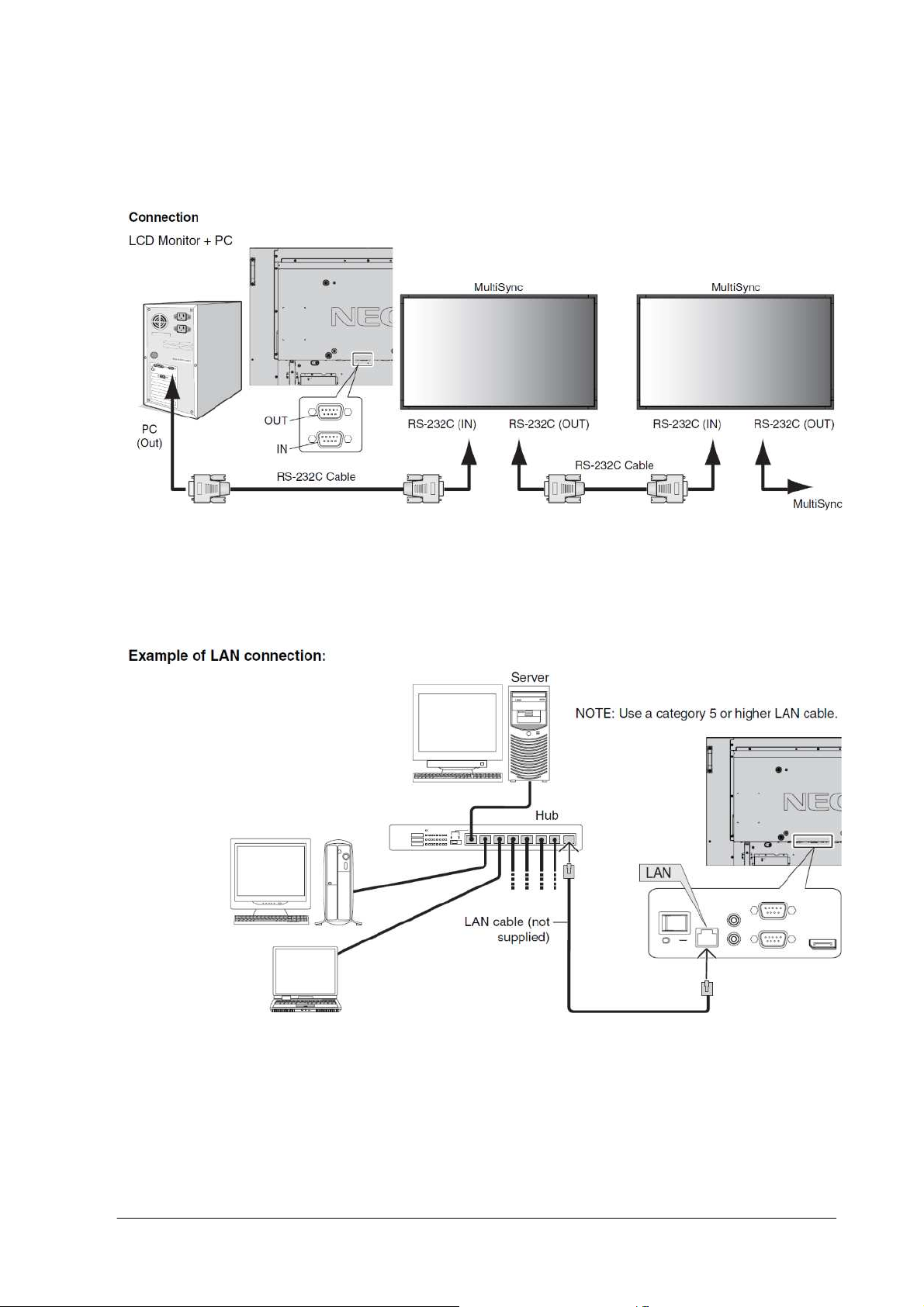
2.1 RS-232C Remote control
2.2 LAN control
III. Communication specification
3. Communication Parameter
3.1 RS-232C Remote control
3.2 LAN control
3.3 Communication timing
4. Communication Format
4.1 Header block format (fixed length)
4.2 Message block format
4.3 Check code
4.4 Delimit er
5. Message type
5.1 Get curr ent Parameter fro m a mo n i tor.
...............................................................................4
....................................................................4
...............................................................4
...........................................................................4
...............................................................5
................................................................5
...............................................................5
...........................................................................5
.................................................................5
...................................................................6
.................................................................9
..........................................................................11
............................................................................12
...........................................................................13
......................................................7
.................................................13
5.2 "Get paramet e r " reply
5.3 Set parameter
5.4 "Se t para meter" reply
5.5 Commands
5.5.1 Save Current Settings
5.5.2 Get Ti m i ng Report and Timing reply.
5.5.3 NULL Message
IV. Control Commands
6. Typical procedure example
6.1. How to change the “Backlight” setting.
6.2. How to read the measurement value of the built-in temperature sensors.
6.3. Operation Code (OP code) Table
7. Power control procedure
7.1 Po wer status read
7.2 Po wer control
8. Asset Data read and write
........................................................................15
...........................................................................17
........................................................................37
.................................................................14
.................................................................16
.............................................................17
................................................18
....................................................................19
.......................................................................20
...............................................................20
................................................20
.......................................................26
.................................................................35
....................................................................35
................................................................39
..................23
8.1 As s e t Data Read Request and reply
8.2 As s e t Data write
.....................................................................41
....................................................39
(1/71)
Page 2

9. Date & Time read and write
..............................................................43
9.1 Date & Time Read
9.2 Date & Time W r ite
10. Schedule read and write
10.1 S chedule Read
10.2 S chedule Write
11. Self diagnosis
11.1 S elf-diagnosis status read
12. Serial No. & Model Name Read
12.1 S er ial No. Read
12.2 Model Name Read
13. Security Lock
13.1 S ecurity Lock Control
14. Direct TV Chanel Read & Write
14.1 Di rect T V Chanel Read & Reply
14.2 Di rect T V Chanel Write & Reply
....................................................................43
....................................................................45
......................................................................48
......................................................................53
..........................................................................63
.....................................................................65
...................................................................66
..........................................................................67
................................................................48
............................................................63
..........................................................65
................................................................67
..........................................................69
.......................................................69
.......................................................70
(2/71)
Page 3

I. Application
This document defines the communications method for control of the NEC LCD monitor, MultiSync P402
/P462 /P552 /P702 /V422 /V462 /V551 /V651 /X461S /X551S /X463UN /X551UN when using an external
controller
.
(3/71)
Page 4
II. Preparation
2. Connectors and wiring
2.1 RS-232C Remote control
Connector: 9-pin D-Sub
Cable: Cross (reversed) cable or null modem cable
(Please refer “Controlling the LCD monitor via RS-232C Remote control” on User’s manual.)
2.2 LAN control
Connector: RJ-45 10/100 BASE-T
Cable: Category 5 or higher LAN cable
(Please refer “Controlling the LCD monitor via LAN control” on User’s manual.)
(4/71)
Page 5

III. Communication specification
3. Communication Parameter
3.1 RS-232C Remote control
(1) Communication system Asynchronous
(2) Interface RS-232C
(3) Baud rate 9600bps
(4) Data length 8bits
(5) Parity None
(6) Stop bit 1 bit
(7) Communication code ASCII
3.2 LAN control
(1) Communication system TCP/IP (Internet protocol suite)
(2) Interface Ethernet (CSMA/CD)
(3) Communication layer Transport layer (TCP)
* Using the payload of TCP segment.
(4) IP address (Default) 192.168.0.10
* If you need to change,
Please refer “Network settings” on User’s manual.
(5) Port No. 7142 (Fixed)
(Note)
The monitor will disconnect the connection if no packet data is received for 15 minutes.
And the controller (PC) has to re-connect to control the monitor again , after 15 minutes or more.
3.3 Communication timing
The controller should wait for a packet interval before next command is sent.
The packet interval needs to be longer than 600msec for the LCD monitor.
(5/71)
Page 6

Header
Delimiter
Header
Delimiter
Header
Delimiter
Header
Delimiter
Header
Delimiter
Header
Delimiter
Header
Delimiter
Header
Delimiter
Header
Delimiter
Header
Delimiter
4. Communication Format
Header Message Check Code Delimiter
The command packet consists of four parts, Header, Message, Check code and Delimiter.
Recommended sequence of a typical procedure to control a monitor is as follows,
[A controller and a monitor, two-way communication composition figure]
■
For the general command (see the part "6.3. Operation Code (OP code) Table”)
Get Parameter
Message
Check Code
Get Parameter Reply
Message
Check Code
Set Parameter
Message
Check Code
Set Parameter Reply
Message
Check Code
Get Parameter
Message
Check Code
Get Parameter Reply
Message
Check Code
Save Current Setting Command
Message
Check Code
Save Current Setting Command Reply
Message
Check Code
Monitor Controller
The controller send s command to
get a value from the monitor that
you want to change.
The monitor replies a current va lue
of the requested item.
The controller sends commands to
set an adjusted value.
The monitor replies to the
controller for confirmation.
The controller sends command to
get a value for confirmation.
The monitor replies an adjusted
value.
The controller requests to store
the adjusted value to the monitor.
The mo nitor replies to the
controller for confirmation.
■
For the special command (see the part 7 to 14. and 5.5.2)
Command
Message
Command Reply
Message
Check Code
Check Code
(6/71)
Monitor Controller
The control does not suitable for
above fixed protocol; use the
proper command for each control.
Please refer section 5.5 and
section 7 to 13.
The monitor replies a proper
message defined for each control.
Page 7

Destination
Destination
Destination
Destination
Destination
4.1 Header block format (fixed length)
Header
Message Check code Delimiter
SOH
1st 2nd 3rd 4th 5th 6th -7th
Reserved
'0'
Destination Source
Message
Type
Message
Length
1stbyte) SOH: Start of Header
ASCII SOH (01h)
nd
2
byte) Reserved: Reserved for future extensions.
On this monitor, it must be ASCII '0'(30h).
rd
3
byte) Destination: Destination equipment ID. (Receiver)
Specify a commands receiver’s address.
The controller sets the “MONITOR ID” or “GROUP ID” of the monitor controlled in here.
On the reply, the monitor sets ‘0’ (30h), always.
“MONITOR ID”, “GROUP ID” to “Destination Address” conversion table is as follows,
Monitor
ID
1 41h(‘A’) 26 5Ah(‘Z’) 51 73h 76 8Ch
2 42h(‘B’) 27 5Bh 52 74h 77 8Dh
3 43h(‘C’) 28 5Ch 53 75h 78 8Eh
4 44h(‘D’) 29 5Dh 54 76h 79 8Fh
5 45h(‘E’) 30 5Eh 55 77h 80 90h
6 46h(‘F’) 31 5Fh 56 78h 81 91h
7 47h(‘G’) 32 60h 57 79h 82 92h
8 48h(‘H’) 33 61h 58 7Ah 83 93h
9 49h(‘I’) 34 62h 59 7Bh 84 94h
10 4Ah(‘J’) 35 63h 60 7Ch 85 95h
11 4Bh(‘K’) 36 64h 61 7Dh 86 96h
12 4Ch(‘L’) 37 65h 62 7Eh 87 97h
13 4Dh(‘M’) 38 66h 63 7Fh 88 98h
14 4Eh(‘N’) 39 67h 64 80h 89 99h
15 4Fh(‘O’) 40 68h 65 81h 90 9Ah
16 50h(‘P’) 41 69h 66 82h 91 9Bh
17 51h(‘Q’) 42 6Ah 67 83h 92 9Ch
18 52h(‘R’) 43 6Bh 68 84h 93 9Dh
19 53h(‘S’) 44 6Ch 69 85h 94 9Eh
20 54h(‘T’) 45 6Dh 70 86h 95 9Fh
21 55h(‘U’) 46 6Eh 71 87h 96 A0h
22 56h(‘V’) 47 6Fh 72 88h 97 A1h
23 57h(‘W’) 48 70h 73 89h 98 A2h
24 58h(‘X’) 49 71h 74 8Ah 99 A3h
25 59h(‘Y’) 50 72h 75 8Bh 100 A4h
ALL 2Ah(‘*’)
Group
ID
A 31h(‘1’) D 34h(‘4’) G 37h(‘7’) J 3Ah(‘:’)
B 32h(‘2’) E 35h(‘5’) H 38h(‘8’)
C 33h(‘3’) F 36h(‘6’) I 39h(‘9’)
Destination
Address
Destination
Address
Monitor
ID
Group
ID
Address
Address
Monitor
ID
Group
ID
Address
Address
Monitor
ID
Group
ID
Address
Destination
Address
Ex.) If you want to control a monitor that has the "ID No." as '1', specify a destination address
(7/71)
Page 8

'A'(41h). If you want to control all of the monitors which are connected by a daisy chain, specify
a destination address ‘
*
’(2Ah).
th
4
byte) Source: Source equipment ID. (Sender)
Specify a sender address.
The controller must be ‘0’ (30h).
On the reply, the monitor sets the own MONITOR ID in here.
th
5
byte) Message Type: (Case sensitive.)
Refer to section 4.2 “Message block format” for more details.
ASCII 'A' (41h): Command.
ASCII 'B' (42h): Command reply.
ASCII 'C' (43h): Get current parameter from a monitor.
ASCII 'D' (44h): "Get parameter" reply.
ASCII 'E' (45h): Set parameter.
ASCII 'F' (46h): "Set parameter" reply.
th
6
-7th bytes) Message Length:
Specify the length of the message (that follows the header) from STX to ETX.
This length includes STX and ETX.
The byte data must be encoded to ASCII characters.
Ex.) The byte data 3Ah must be encoded to ASCII characters '3' and 'A' (33h and 41h).
The byte data 0Bh must be encoded to ASCII characters '0' and 'B' (30h and 42h).
(8/71)
Page 9

Lo Hi Lo
Hi Lo Hi Lo Hi Lo
4.2 Message block format
“Message block format” is allied to the “Message Type” in the “Header”.
Refer to the section 6 “Message format” for more detail.
1
)
Get currentparameter
The controller sends this message when you want to get the status of the monitor.
For the status that you want to get, specify the “OP code page” and “OP code”,
refer to “Appendix A. Operation code table”.
“Message format” of the “Get current
2
)
Get Parameter reply
The monitor will reply with the status of the requested item specified by the controller
in the “Get parameter message”.
STX
Hi
STX
Refer to section 5.1 “Get current parameter from a monitor.” for more details.
“Message format” of the “Get parameter reply” is as follows,
Result
Lo Hi Lo Hi Lo Hi Lo MSB
Refer to section 5.2 “Get parameter reply” for more details.
OP code page OP code
Hi Lo Hi Lo
OP code
page
Header
OP code Type Max value Current Value
Message
parameter” is as follows,
Check code Delimiter
ETX
LSB MSB
ETX
LSB
3
)
Set parameter
The controller sends this message to change a setting of the monitor.
Message format of the “Set parameter” is as follows,
OP code
STX
4
)
Set Parameter reply
The monitor replies with this message for a confirmation of the “Set parameter message”.
Message format of the “Set parameter reply” is as follows,
5
)
Command
Result
Hi Lo
STX
page
Hi
Refer to section 5.3 “Set parameter” for more details.
OP code
Refer to section 5.4 “Set parameter reply” for more details.
OP code Set Value
page
OP code
MSB
ETX
LSB
Type Max value
MSB
Requested setting
Value
LSB MSB LSB
ETX
“Command message” format depends on each command.
Usually, this “com mand message” is used for some non-slider controls and some special operations,
such as “Save current settings”, “Get timing report”, “power control”, “Schedule”, etc. Refer to
(9/71)
Page 10

section 5.5 “Commands message” for more details.
6
)
Command reply
The monitor replies to a query from the controller.
“Command reply message” format depends on each command.
Refer to section 5.5 “Commands message” for more details.
(10/71)
Page 11
n+1
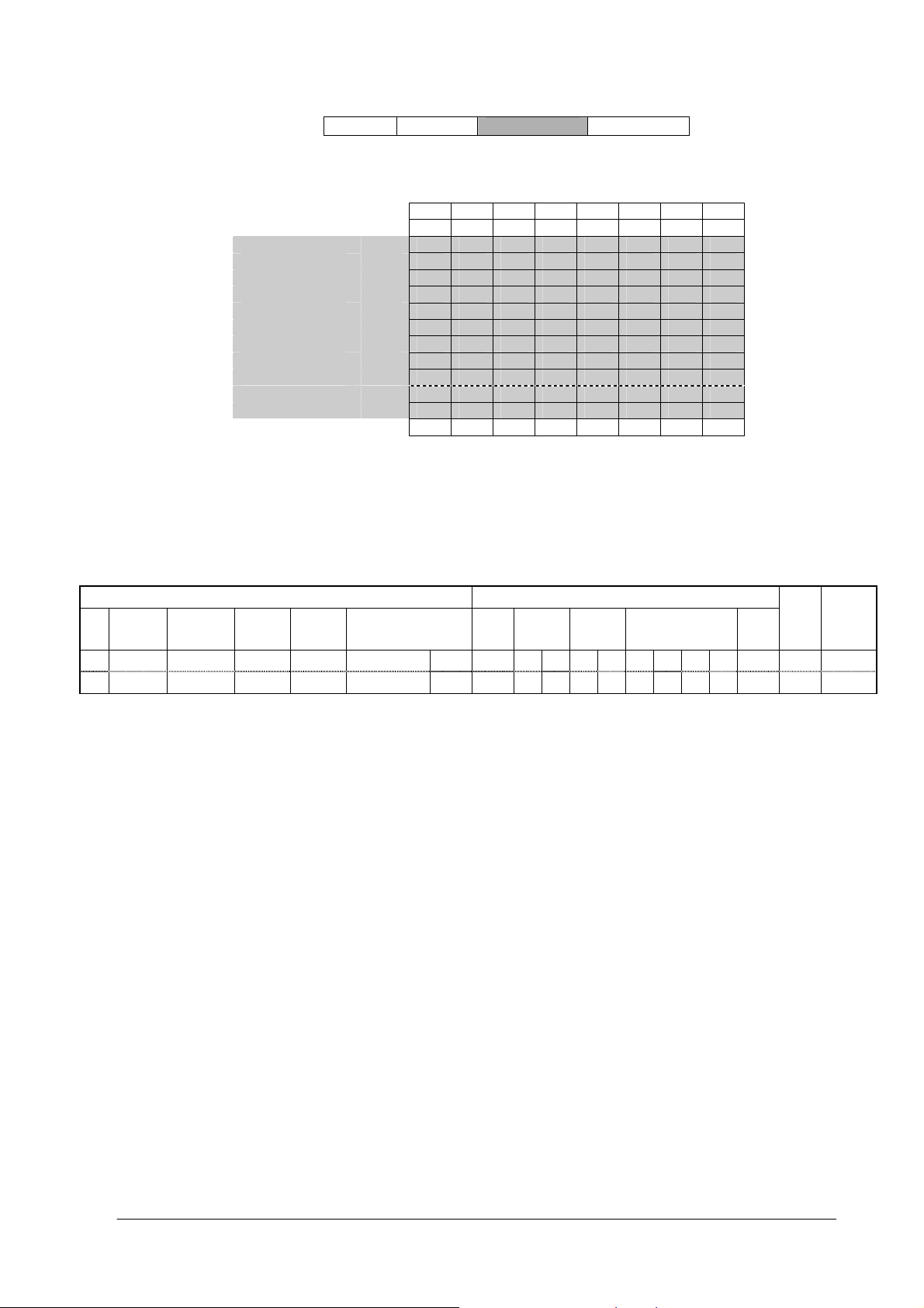
4.3 Check code
Header Message
Check code is the Block Check Code (BCC) between the Header and the End of Message except SOH.
27 26 25 24 23 22 21 20
SOH D0
Reserved D1
Destinatio n D2
Source D3
Type D4
Length(H) D5
Length(L) D6
STX D7
Data D8
| |
| |
ETX Dn
Check code D
P P P P P P P P
D
= D1 XOR D2 XOR D3 XOR ,,, D
n+1
n
XOR: Exclusive OR
Check code
Delimiter
Following is an example of a Check code (BCC) calculation.
Header Message
SOH Reserved
01 30 41 30 45 30 41 02 30 30 31 30 30 30 36 34 03 77 0D
D
0
Destination
Address
D1 D2 D3 D4 D5 D6 D7 D
Source
Address
Message
type
Message length STX
OP code
page
8
OP code Set Value ETX
D
D
D
D
D
9
10
11
12
D
13
14
D
15
Check
Delimiter
code
(BCC)
D
D
16
D18
17
Check code (BCC) D
= D1 xor D2 xor D3 xor … xor D14 xor D15 xor D16
17
= 30h xor 41h xor 30h xor 45h xor 30h xor 41h
xor 02h xor 30h xor 30h xor 31h xor 30h xor 30h
xor 30h xo r 36h xor 34h xor 03h
= 77h
(11/71)
Page 12

4.4 Delimiter
Packet delimite r code; ASCII CR(0Dh).
Header Message Check code
Delimiter
(12/71)
Page 13

5. Message type
5.1 Get current Parameter from a monitor.
STX
OP code page
Hi Lo Hi Lo
1st 2nd-3rd 4th–5th 6
OP code
ETX
th
Send this message when you want to get the status of a monitor.
For the status that you want to get, specify the “OP co de page” the “ OP co de”, refer t o
A. Operati on code table”.
st
1
byte) STX : Start of Message
ASCII STX (02h)
nd-3rd
2
bytes) OP code page: Operation code page.
Specify the “OP code page” for the control which you want to get the status.
Refer to “Appendix A Operation code table” for each item.
OP code page data must be encoded to ASCII characters.
Ex.) The byte data 02h must be encoded to ASCII characters '0' and '2' (30h
and 32h).
OP code page 02h -> OP code page (Hi) = ASCII '0' (30h)
OP code page (Lo) = ASCII '2' (32h)
“Appendix
Refer to Operation code table. (Appendix A)
th–5th
4
bytes) OP code: Operation code
Refer to “Appendix A Operation code table” for each item.
OP code data must be encoded to ASCII characters.
Ex.) The byte data 3Ah must be encoded to ASCII characters '3' and 'A' (33h and 41h).
OP code 3Ah -> OP code (Hi) = ASCII '3' (33h)
OP code (Lo) = ASCII 'A' (41h)
Refer to Operation code table.
th
6
byte) ETX: End of Message
ASCII ETX (03h)
(13/71)
Page 14

5.2 "Get parameter" reply
STX
st
1
Result OP code page
OP code
Hi Lo Hi Lo Hi Lo Hi Lo MSB
2nd-3rd 4th–5th 6th –7th 8th -9
Type Max value Current Value
th
10th -13th 14th -17th 18th
LSB MSB
LSB
The monitor replies with a current value and the status of the requested it em (operation code).
st
1
byte) STX: Start of Message
ASCII STX (02h)
nd-3rd
2
bytes) Result code.
These bytes indicate a result of the requested commands as follows,
00h: No Error.
01h: Unsupported operation with this monito r or unsupported operation u nder current condition.
This result code from the monitor is encoded to ASCII characters.
Ex.) The byte data 01h is encoded to ASCII character '0' and '1' (30h and 31h).
th–5th
4
bytes) OP code page: Operation code page.
These bytes indicate a replying item's OP code page.
This returned value from the monitor is encoded to ASCII characters.
Ex.) The byte data 02h is encoded to ASCII character '0' and '2' (30h and 32h).
ETX
Refer to the operation code table.
th
6
–7thbytes) OP code: Operation code
These bytes indicate a replying item's OP code.
This returned value from the monitor is encoded to ASCII characters.
Refer to the operation code table.
Ex.) The byte data 1Ah is encoded to ASCII character '1' and 'A' (31h and 41h).
th
8
-9thbytes) Type: Operation type code
00h: Set parameter
01h: Momentary
Like the Auto Setup function which automatically changes the parameter.
This returned value from the monitor is encoded to ASCII characters.
Ex.) The byte data 01h is encoded to ASCII character '0' and '1' (30h and 31h).
th
10
-13thbytes) Max. value: Maximum value which monitor can accept. (16bits)
This returned value from the monitor is encoded to ASCII characters.
Ex.) '0','1','2' and '3' means 0123h (291)
th
14
-17thbytes) Current Value: (16bits)
This returned value from the monitor is encoded to ASCII characters.
Ex.) '0','1','2' and '3' means 0123h (291)
th
18
byte) ETX: End of Message
ASCII ETX (03h)
(14/71)
Page 15

5.3 Set parameter
th
STX
st
1
OP code page
OP code
Hi Lo Hi Lo MSB
2nd-3rd 4th-5th 6th-9th 10
Set Value
LSB
ETX
Send this message to change monitor’s adjustment and so on.
The controller requests a monitor to change value.
st
1
byte) STX: Start of Message
ASCII STX (02h)
nd-3rd
2
bytes) OP code page: Operation code page
This OP code page data must be encoded to ASCII characters.
Ex.) The byte data 02h must be encoded to ASCII '0' and '2' (30h and 32h).
Refer to the Operation code table.
th-5th
4
bytes) OP code: Operation code
This OP code data must be encoded to ASCII characters.
Ex.) OP code 1Ah -> OP code (Hi) = ASCII '1' (31h)
OP code (Lo) = ASCII 'A' (41h)
Refer to the Operation code table.
th-9th
6
bytes) Set value
: (
16bit)
This data must be encoded to ASCII characters.
Ex.) 0123h -> 1
2
3
4
th
10
byte) ETX: End of Message
st
(MSB) = ASCII '0' (30h)
nd
= ASCII '1' (31h)
rd
= ASCII '2' (32h)
th
(LSB) = ASCII '3' (33h)
ASCII ETX (03h)
(15/71)
Page 16

Hi Lo Hi
5.4 "Set parameter" reply
STX
st
1
Result OP code page
Lo Hi Lo Hi Lo MSB
OP code
Type Max value
LSB MSB
Requested setting
Value
LSB
2nd-3rd 4th-5th 6th-7th 8th-9th 10th-13th 14th -17th 18
The Monitor echoes back the parameter and status of the requested operation code.
st
1
byte) STX: Start of Message
ASCII STX (02h)
nd-3rd
2
bytes) Result code
ASCII '0''0' (30h, 30h): No Error.
ASCII '0''1' (30h, 31h): Unsupported operation with this monitor or unsupported operation under
current condition.
th-5th
4
bytes) OP code page: Echoes back the Operation code page for confirmation.
Reply data from the monitor is encoded to ASCII characters.
Ex.) OP code page 02h -> OP code page = ASCII '0' and '2' (30h and 32h)
Refer to Operation code table.
th-7th
6
bytes) OP code: Echoes back the Operation code for confirmation.
Reply data from the monitor is encoded to ASCII characters.
ETX
th
Ex.) OP code 1Ah -> OP code (Hi) = ASCII '1' (31h)
OP code (Lo) = ASCII 'A' (41h)
Refer to Operation code table
th-9th
8
bytes) Type: Operation type code
ASCII '0''0' (30h, 30h): Set parameter
ASCII '0''1' (30h, 31h): Momentary
Like Auto Setup function, that automatically changes the parameter.
th
10
-13thbytes) Max. value: Maximum value that monitor can accept. (16bits)
Reply data from the monitor is encoded to ASCII characters.
Ex.) '0''1''2''3' means 0123h (291)
th
14
-17thbytes) Requested setting Value: Echoes back the parameter for confirmation. (16bits)
Reply data from the monitor is encoded to ASCII characters.
Ex.) '0''1''2''3' means 0123h (291)
th
18
byte) ETX: End of Message
ASCII ETX (03h)
(16/71)
Page 17

5.5 Commands
"Command message format" depends on each command
section 7 to 13.
.
Some commands are shown with usage. Refer to
5.5.1 Save Current Settings.
The controller requests for the monitor to store the adjusted value.
STX
ASCII: 01h-30h-41h-30h-41h-30h-34h-02h-30h-43h-03h-CHK-0Dh
The monitor replies the packet for confirmation as follows;
SOH-'0'-'0'-'A'-'B'-'0'-'6'-STX-'0'-'0'-'0'-'C'-ETX-CHK- CR
Command code
'0' 'C'
Send "OC"(30h, 43h) as Save current settings command.
Complete "Save Current setting" command packet as follows;
SOH-'0'-'A'-'0'-'A'-'0'-'4'-STX-'0'-'C'-ETX-CHK- CR
ETX
(17/71)
Page 18

5.5.2 Get Timing Report and Timing reply.
The controller requests the monitor to report the displayed image timing.
STX
ASCII: 01h-30h-41h-30h-41h-30h-34h-02h-30h-37h-03h-CHK-0Dh
The monitor replies status as the following format;
STX
Command code
'0' '7'
Send "07"(30h, 37h) as Get Timing Report command.
Complete "Get Timing Report" command packet as follows;
SOH-'0'-'A'-'0'-'A'-'0'-'4'-STX-'0'-'7'-ETX-CHK- CR
Command SS H Freq. V Freq.
'4' 'E' Hi Lo MSB LSB MSB LSB
SS: Timing status byte
Bit 7 = 1: Sync Frequency is out of range.
Bit 6 = 1: Unstable count
Bit 5-2 Reserved (Don't care)
Bit 1 1:Positive Horizontal sync polarity.
0:Negative Horizontal sync polarity.
Bit 0 1:Positive Vertical sync polarity.
H Freq: Horizontal Frequency in unit 0.01kHz
V Freq: Vertical Frequency in unit 0.01Hz
Ex.) When H Freq is '1''2''A''9' (31h, 32h, 41h, 39h), it means 47.77kHz.
ETX
0:Negative Vertical sync polarity.
ETX
(18/71)
Page 19

5.5.3 NULL Message
STX
The NULL message returned from the monitor is used in the following cases;
01h-30h-30h-41h-42h-30h-34h-02h-42h-45h-03h-CHK-0Dh
SOH-'0'-'0'-'A'-'B'-'0'-'4'-STX-'B'-'E'-ETX-CHK- CR
Command code
'B' 'E'
To tell the controlle r that the monitor does n ot have any answer to give to the host (not
ready or not expected)
Following operations need a certain time for to execute, so the monitor will return this
message wh en another message is received during execution.
Power ON, Power OFF, Auto Setup, Input, PIP Input, Auto Setup and Factory reset.
Complete "NULL Message" command packet as follows;
ETX
(19/71)
Page 20

IV. Control Commands
6. Typical procedure example
The following is a sample of procedures to control the monitor, these are examples of "Get parameter",
"Set parameter" and "Save current settings".
6.1. How to change the “Backlight” setting.
Step 1. The controller requests the Monitor to reply with the current brightness setting and capability
to support this operation. (Get parameter)
Header Message Chec k code Delimiter
SOH-'0'-Mo nitor ID-'0'-'C '-'0'-'6' STX-'0'-'0 '-'1'-'0'-ETX BCC CR
Header
SOH (01h): Start Of Header
'0' (30h): Reserved
Monitor ID: Specify the Monitor ID from which you want to get a value.
Ex.) If Monitor ID is '1', specify 'A'.
'0' (30h): Message sender is the controller.
'C' (43h): Message type is "Get parameter command".
'0'-'6' (30h, 36h): Message length is 6 bytes.
Message
STX (02h): Start of Message
'0'-'0' (30h, 30h): Operation code page number is 0.
'1'-'0' (31h, 30h): Operation code is 10h (in the OP code page 0).
ETX (03h): End of Message
Check code
BCC: Block Check Code
Refer to the section 4.5 “Check code” for a BCC calculation.
Delimiter
CR (0Dh): End of packet
Step 2. The monitor replies with current Backlight setting and capability to support this operation.
Header Message Check code
SOH-'0'-'0'-Monitor ID-'D'-'1'-'2' STX-'0'-'0'-'0'-'0'-'1'-'0'-'0'-'0'
-'0'-'0'-'6'-'4'-'0'-'0'-'3'-'2'-ETX
Header
SOH (01h): Start Of Header
'0' (30h): Reserved
'0' (30h): Message receiver is the controller.
Monitor ID: Indicate a replying Monitor ID.
Ex.) When this byte is set to 'A', the replying Monitor ID is '1'.
'D' (44h): Message Type is "Get parameter reply".
'1'-'2' (31h, 32h): Message length is 18 bytes.
Message
STX (02h): Start of Message
'0'-'0' (30h, 30h): Result code. No error.
'0'-'0' (30h, 30h): Operation code page number is 0.
'1'-'0' (31h, 30h): Operation code is 10h (in the page 0).
'0'-'0' (30h, 30h): This operation is "Set parameter" type.
'0'-'0'-'6'-'4' (30h, 30h, 36h, 34h): Backlight max value is 100(0064h).
'0'-'0'-'3'-'2' (30h, 30h, 33h, 32h): Current Backlight setting is 50(0032h) .
ETX (03h): End of Message
Check code
BCC: Block Check Code
Refer to the section 4.5 “Check code” for a BCC calculation.
Delimiter
BCC CR
Delimiter
(20/71)
Page 21

CR (0Dh): End of packet
Step 3. The controller request the monitor to change the Backlight setting
Header Message
SOH-'0'-Monitor ID-'0'-'E'-'0'-'A' STX-'0'-'0'-'1'-'0'-'0'-'0'-'5'-'0'-ETX BCC CR
Header
SOH (01h): Start Of Header
'0' (30h): Reserved
Monitor ID: Specify the Monitor ID of which you want to change a setting.
Ex.) If Monitor ID is '1', specify 'A'.
'0' (30h): Message sender is the controller.
'E' (45h): Message Type is "Set parameter command".
'0'-'A' (30h, 41h): Message length is 10 bytes.
Message
STX (02h): Start of Message
'0'-'0' (30h, 30h): Operation code page number is 0.
'1'-'0' (31h, 30h): Operation code is 10h (in the page 0).
'0'-'0'-'5'-'0' (30h, 30h, 35h, 30h): Set Backlight setting 80(0050h).
ETX (03h): End of Message
Check code
BCC: Block Check Code
Refer to the section 4.5 “Check code” for a BCC calculation.
Delimiter
CR (0Dh): End of packet
Step 4. The monitor replies with a message for confirmation.
Header Message Check code Delimiter
SOH-'0'-'0'- Monitor ID -'F'-'1'-'2' STX-'0'-'0'-'0'-'0'-'1'-'0'—'0'-'0'-'0'
-'0'-'6'-'4'-'0'-'0'-'5'-'0'-ETX
Header
SOH (01h): Start Of Header
'0' (30h): Reserved
'0' (30h): Message receiver is the controller.
Monitor ID: Indicate a replying Monitor ID.
Ex.) When this byte is set to 'A', the replying Monitor ID is '1'.
'F' (46h): Message Type is "Set parameter reply".
'1'-'2' (31h, 32h): Message length is 18 bytes.
Message
STX (02h): Start of Message
'0'-'0' (30h, 30h): Result code. No error.
'0'-'0' (30h, 30h): Operation code page number is 0.
'1'-'0' (31h, 30h): Operation code is 10h (in the page 0).
'0'-'0' (30h, 30h): This operation is "Set parameter" type.
'0'-'0'-'6'-'4' (30h, 30h, 36h, 34h): Backlight max value is 100(0064h).
'0'-'0'-'5'-'0' (30h, 30h, 35h, 30h): Received a Backlight setting was 80(0050h) .
ETX (03h): End of Message
Check code
BCC: Block Check Code
Refer to the section 4.5 “Check code” for a BCC calculation.
Delimiter
CR (0Dh): End of packet
Repeat Step 1 and Step 2, if you need to check the Backlight setting. (Recommended)
Step 5. Request the monitor to store the Backlight setting. (Save Current Settings Command)
Check
code
BCC CR
Delimiter
(21/71)
Page 22

Header Message Check code Delimiter
SOH-'0'-Monitor ID-'0'-'A'-'0'-'4' STX-'0-'C'-ETX BCC CR
Header
SOH (01h): Start Of Header
'0' (30h): Reserved
Monitor ID: Specify the Monitor ID which you want to store the setting.
Ex.) If Monitor ID is '1', specify 'A'.
'0' (30h): Message sender is the controller.
'A' (41h): Message type is "Command".
'0'-'4' (30h, 34h): Message length is 4 bytes.
Message
STX (02h): Start of Message
'0'-'C' (30h, 43h): Command code is 0Ch as "Save current settings".
ETX (03h): End of Message
Check code
BCC: Block Check Code
Refer to the section 4.5 “Check code” for a BCC calculation.
Delimiter
CR (0Dh): End of packet
(22/71)
Page 23

6.2. How to read the measurement value of the built-in temperature sensors.
MultiSync P402 /P462 /P 55 2 /P702 /V422 /V462 /V551 /V651 / X461S /X551S /X463UN /X551UN have three
built-in t emperature sensors.
The controller can monitor inside temperatures by using those sensors with external control.
The following shows the procedure for reading the temperatures from the sensors.
Step 1. Select a temperature sensor which you want to read.
Header Message
SOH-'0'-Monitor ID-'0'-'E'-'0'-'A' STX-'0'-'2'-'7'-'8'-'0'-'0'-'0'-'1'-ETX BCC CR
Header
SOH (01h): Start of Header
'0' (30h): Reserved
Monitor ID: Specify the Monitor ID which you want to get a value.
Ex.) If Monitor ID is '1', specify 'A'.
'0' (30h): Message sender is the controller.
'E' (45h): Message Type is "Set parameter command".
'0'-'A' (30h, 41h): Message length is 10 bytes.
Message
STX (02h): Start of Message
'0'-'2' (30h, 32h): Operation code page number is 2.
'7'-'8' (37h, 38h): Operation code is 78h (on page 2).
'0'-'0'-'0'-'1' (30h, 30h, 30h, 31h): Select the temperature sensor #1 (01h).
00h: No meaning
01h: Sensor #1
02h: Sensor #2
03h: Sensor #3
ETX (03h): End of Message
Check code
BCC: Block Check Code
Refer to the section 4.5 “Check code” for a BCC calculation.
Delimiter
CR (0Dh): End of packet
Step 2. The monitor replies for confirmation.
Check
code
Delimiter
Header Message
SOH-'0'-'0'-Monitor ID-'F'-'1'-'2' STX-'0'-'0'-'0'-'2'-'7'-'8'-'0'-'0'-'0'-'0'
-'0'-'3'-'0'-'0'-'0'-'1'-ETX
Header
SOH (01h): Start of Header
'0' (30h): Reserved
'0' (30h): Message receiver is the controller.
Monitor ID: Indicates a replying Monitor ID.
Ex.) When this byte is set to 'A', the replying Monitor ID is '1'.
'F' (46h): Message Type is "Set parameter reply".
'1'-'2' (31h, 32h): Message length is 18 bytes.
Message
STX (02h): Start of Message
'0'-'0' (30h, 30h): Result code. No error.
'0'-'2' (30h, 32h): Operation code page number is 2.
'7'-'8' (37h, 38h): Operation code is 78h (in the page 2).
(23/71)
Check
code
BCC CR
Delimiter
Page 24

'0'-'0' (30h, 30h): This operation is "Set parameter" type.
'0'-'0'-'0'-'3' (30h, 30h, 30h, 33h): Number of temperature sensors are 3 (0003h).
'0'-'0'-'0'-'1' (30h, 30h, 30h, 31h): temperature sensor is #1.
ETX (03h): End of Message
Check code
BCC: Block Check Code
Refer to the section 4.5 “Check code” for a BCC calculation.
Delimiter
CR (0Dh): End of packet
Step 3. The controller requests the monitor to send the temperature from the selected sensor.
Header Message Check code
Delimiter
SOH-'0'-Monitor ID-'0'-'C'-'0'-'6' STX-'0'-'2'-'7'-'9'-ETX BCC CR
Header
SOH (01h): Start of Header
'0' (30h): Reserved
Monitor ID: Specify the Monitor ID which you want to get a value.
Ex.) If Monitor ID is '1', specify 'A'.
'0' (30h): Message sender is the controller.
'C' (43h): Message Type is "Get parameter".
'0'-'6' (30h, 36h): Message length is 6 bytes.
Message
STX (02h): Start of Message
'0'-'2' (30h, 32h): Operation code page number is 2.
'7'-'9' (37h, 39h): Operation code is 79h (in the page 2).
ETX (03h): End of Message
Check code
BCC: Block Check Code
Refer to the section 4.5 “Check code” for a BCC calculation.
Delimiter
CR (0Dh): End of packet
Step 4. The monitor replies a temperature of selected sensor.
Header Message Check code
SOH-'0'-'0'-Monitor ID-'D'-'1'-'2' STX-'0'-'0'-'0'-'2'-'7'-'9'-'0'-'0'
BCC CR
-'F'-'F'-'F'-'F'-'0'-'0'-'3'-'2'-ETX
Header
SOH (01h): Start of Header
'0' (30h): Reserved
'0' (30h): Message receiver is the controller.
Monitor ID: Indicate a replying Monitor ID.
Ex.) When this byte is set to 'A', the replying Monitor ID is '1'.
'D' (44h): Message Type is "Get parameter reply".
'1'-'2' (31h, 32h): Message length is 18 bytes.
Message
STX (02h): Start of Message
'0'-'0' (30h, 30h): Result code. No error.
'0'-'2' (30h, 32h): Operation code page number is 2.
'7'-'9' (37h, 39h): Operation code is 79h (in the page 2).
'0'-'0' (30h, 30h): This operation is "Set parameter" type.
'F'-'F'-'F'-'F' (46h, 46h, 46h, 46h): Maximum value.
'0'-'0'-'3'-'2' (30h, 30h, 33h, 32h): The temperature is 25 degrees Celsius.
Delimiter
(24/71)
Page 25

Readout value is 2's complement.
ETX (03h): End of Message
Check code
BCC: Block Check Code
Refer to the section 4.5 “Check code” for a BCC calculation.
Delimiter
CR (0Dh): End of packet
Temperature [Celsius]
+125.0 0000 0000 1111 1010 00FAh
+ 25.0 0000 0000 0011 0010 0032h
+ 0.5 0000 0000 0000 0001 0001h
0 0000 0000 0000 0000 0000h
- 0.5 1111 1111 1111 1111 FFFFh
- 25.0 1111 1111 1100 1110 FFCEh
- 55.0 1111 1111 1001 0010 FF92h
Readout value
Binary Hexadecimal
(25/71)
Page 26

6.3. Operation Code (OP code) Table
s
Each needs an
ment by
Item OP
Backlight 00h 10h 0: dark
Contrast 00h 12h 0: low
Sharpness 00h 8Ch 0: dull
Brightness 00h 92h 0: dark
Hue 00h 90h 0: purplish
Color 02h 1Fh 0: pale
Color Temperature 00h 54h 0:2600K
Color control 00h Red: 9Bh
Gamma Correction 02h 68h Gamma
PICTURE
Movie
Settings
Picture mo de 02h 1Ah 1: sRGB
Ambient
Adaptive
Contrast
Noise
Reduction
Telecine 02h 23h 1: Off
Ambient
Brightness
Low
Ambient
Brightness
High
OP code Parameter Re ma rk s
code
page
|
100(64h): bright
|
100(64h): high
|
24(18h): sharp
|
100(64h): bright
|
100(64h): greenish
|
100(64h): deep
|
74(4Ah):10000K
0:
Yellow: 9Ch
Green: 9Dh
Cyan: 9Eh
Blue: 9Fh
Magenta: A0h
02h 8Dh 0: None
02h 26h 0: Off
10h 33h 0: dark
10h 34h 0: dark
|
100(64h):(center)
|
200(C8h):
Table Selection
1: Native
4: Gamma=2.2
8: Gamma=2.4
7: S Gamma
5: DICOM SIM.
6: Programmable
1: Off
2: Low
3: Middle
4: High
|
5: High
2: Auto
3: Hi-Brig ht
4: Standar d
5: Cinema
6: ISF-Day
7: ISF-Nig ht
11(0Bh): A mbient-1
12(0Ch): A mbient-2
|
100(64h): bright
|
100(64h): bright
Gamma
100K/step
Page02-20
also works a
same.
sRGB:
PC mode only
Cinema:
A/V mode only
ISF-Day:
ISF-Night:
adjust
ISF.
(26/71)
Page 27

Item OP
Get Current
on a
on a
OP code Parameter Remarks
code
page
02h B4h 0:
Illuminance
Bright
Sensor Read
02h B5h 0:
|
Max.
|
255(FFh)
Menu tree reset
(Picture)
02h CBh 0: None
2: Reset
Picture category
Auto Setup 00h 1Eh 1: Execute Momentary
Auto Adjust N/A
H Position 00h 20h 0: Left side
|
Max.: Right side
V Position 00h 30h 0: Bottom side
|
Max.: Top side
Clock 00h 0Eh 0:
|
Max. :
Phase 00h 3Eh 0:
|
Max. :
H Resolution 02h 50h 0: Low
|
Max. : High
V Resolution 02h 51h 0: Low
|
Max.: High
Input Resolution 02h DAh
ADJUST
Input Resolution select
0:no mean
1:Item 1(always Auto)
2:Item 2
3:Item 3
4:Item 4
5:Item 5
Over5:Ignore
Ex)
Item 1= AUTO
Item 2= -- /
1024x768 /
1400x1050 /
800x600 /
1280x960
Item 3= -- /
1280x768 /
1680x1050 /
1024x576 /
1600x900 /
Item 4= -- /
1360x768 /
-- /
-- /
--
Item 5= -- /
1366x768
-- /
-- /
--
Read only
Read only
Momentary
Depends
display
timing
Depends
display
timing
(27/71)
Page 28

Item OP
Not available
available
Not availab le
t available
code
page
Aspect 02h 70h 0: No operate
Zoom Control
Menu tree reset
(Adjust)
Volume 00h 62h 0: whisper
Balance 00h 93h O: Left
Treble 00h 8Fh O: Min.
Bass 00h 91h 0: Min.
Zoom 02h 6Fh
Zoom
H-Expansion
Zoom
V-Expansion
Zoom
H-Position
Zoom
V-Position
02h 6Ch
02h 6Dh
02h CCh 0: Left side
02h CDh 0: Down side
02h CBh 0: None
AUDIO
PIP Audio 10h 80h 0: No operate
Line out 10h 81h 0: No operate
SURROUND 02h 34h 1: Off
Audio Inpu t 02h 2Eh 1: Audio 1(PC)
OP code Parameter Remarks
1: Normal
2: Full
3: Wide
4: Zoom
5: (reserved)
6: Dynamic
7: Off (dot by dot)
1:100
2:101
|
201:300
1:100
2:101
|
201:300
1:100
2:101
|
201:300
|
Max.: Right side
|
Max.: Up s ide
3: Reset
Adjust catego ry
|
100: loud
|
30:(Center )
|
60: Right
|
6:(Center)
|
12: Max.
|
6:(Center)
|
12: Max.
1: Main
2: Sub
1: Fixed
2: Variabl e
2: Low (or On)
3: High (o r On)
2: Audio 2
3: Audio 3
4: HDMI
6: TV/Opti on
7: Display Port
Wide:
Dynamic
A/V mode only
%
%
%
%
%
%
%
%
%
Momentary
00h
on X551UN
Not
on X551UN
on X551UN
No
on X551UN
(28/71)
Page 29

Item OP
code
page
Menu tree reset
(Audio)
Off Timer 02h 2Bh 0: Off
Enable Schedule 02h E5h 0: No Mean
Disable Schedule 02h E6h 0: No Mean
SCHDULE
Menu tree reset
(Schedule)
Keep PIP Mode 10h 82h 0: No operate
PIP Mode 02h 72h 1: Off
PIP Size 02h 71h 1: Small
PIP H Position 02h 74h 0: left
PIP V Position 02h 75h 0: top
Aspect 10h 83h 0: No operate
PIP
Text Ticker
Mode 10h 08h 0: None
Position 10h 09h 0: Top/Left
Size 10h 0Ah 0-1: Do not set.
Blend 10h 0Bh 1: 10%
Detect 10h 0Ch 0: None
02h CBh 0: None
02h CBh 0: None
OP code Parameter Remarks
4: Reset
Audio category
1: 1 hour
|
24: 24 hours
1: No.1 Enable
|
7: No.7 Enable
1: No.1 Disable
|
7: No.7 Disable
5: Reset
Schedule category
1: Off
2: On
2: PIP
3: POP
4: Still
5: Side by side
(aspect)
6: Side by side
(Full)
7: (reserved)
8: (reserved)
2: Middle
3: Large
|
100(64h): right
|
100(64h): bottom
1: Normal
2: Full
3: Wide
4: (reserved)
5: (reserved)
1: Off
2: Horizontal
3: Vertical
|
100: Bottom/Right
2: Narrow(2/24)
|
8: Wide(8/24)
|
10: 100%
1: Auto
2: Off
Momentary
1 hour/step
Momentary
(29/71)
Page 30

Item OP
operation has
limitation of
Please refer
to the
code
page
Fade In 10h 0Dh 0: None
PIP Input(Sub input) 02h 73h 0: No mean
Menu tree reset
(PIP)
Language 00h 68h 1: English
Menu Display Time 00h FCh 0-1: Do not set.
H
Position
Information OSD 02h 3Dh 0:Disable
Position
V
Position
02h CBh 0: None
02h 38h 0: Left
02h 39h 0: Down
OSD
OSD Transparency 02h B8h 0: None
OSD Rotation 02h 41h 0: Normal
Closed Caption 10h 84h 0: No operate
Menu tree reset
(OSD)
02h CBh 0: None
OP code Parameter Remarks
1: On
2: Off
1: VGA
2: RGB/HV
3: DVI
4: HDMI (Set only)
5: Video1
6: Video2
7: S-Video
12(0Ch): DVD/HD1
13(0Dh): Option
14(0Eh): DVD/HD2
15(0Fh): Display
17(11h): HDMI
6: Reset PIP
category
2: German
3: French
4: Spanish
5: Japanese
6: Italian
7: Swedish
9: Russian
14(0Eh): Chinese
2: 10s
3: 15s
|
48: 240s
|
MAX.: Right
|
MAX.: Up
information OSD
3-10:
OSD timer [seconds]
1: Off(Opaque)
2: On(Translucent)
3: (reserved)
1: Rotated
1: Off
2: CC1
3: CC2
4: CC3
5: CC4
6: TT1
7: TT2
8: TT3
9: TT4
7: Reset
OSD category
This
selection.
monitor
instruction
manual.
Port
Momentary
OSD Language
5sec/step
OSD
Momentary
(30/71)
Page 31

Item OP
affects to a
code
page
Monitor ID 02h 3Eh 1-100:ID
Group ID 10h 7Fh 0: No assignment
IR Control 02h 3Fh 1: Normal
Tile
Matrix
MULTI DISPLAY
Power On Delay 02h D8h 0: Off (0sec)
Power Indicator 02h BEh 0: None
control
Setting copy N/A
Menu tree reset
(Multi Display)
Power Save 00h E1h 0: Off
Video Power Save 02h D6h 0: No mean
Fan Control 02h 7Dh 0: None
H monitor 02h D0h 1
V monitor 02h D1h 1
Position 02h D2h 1: Upper left
Tile comp 02h D5h 1: Disable (Off)
Mode 02h D3h 1: Disable (Off)
Control 10h 3Eh 0: No mean
ID=All
Reply
10h 85h 0: No operate
02h CBh 0: None
DISPLAY PROTECTION
Fan Speed 10h 3Fh 0: None
OP code Parameter Remarks
1: Group A
2: Group B
3: Group AB
4: Group C
5: Group AC
│
1023:Group
ABCDEFGHIJ
2: Primary
3: Secondary
4: Lock (Off)
|
10
|
10
|
MAX.: Lower right
2: Enable (On)
and display frame
2: Enable (On)
3: Disable (Off)
and erase frame
(Set only)
│
50:50sec
1: On
2: Off
1: RS-232C
2: LAN
1: On
2: Off
8: Reset
Multi Display
category
1: On
1: Off
2: On
1: Auto(No offset)
2: Forced ON
3: Auto(offset -2)
4: Auto(offset -4)
5: Auto(offset -6)
6: Auto(offset -8)
7: Auto(offset -10)
1: High
2: Low
Bit0:Group A
Bit1:Group B
Bit2:Group C
Bit3:Group D
Bit4:Group E
Bit5:Group F
Bit6:Group G
Bit7:Group H
Bit8:Group I
Bit9:Group J
Number
of H-division
Number
of V-division
External
Momentary
Offset
selected
sensor.
(31/71)
Page 32

Item OP
code
page
Screen Saver
Side Border Color 02h DFh 0: Black
Auto Brightness 02h 2Dh 0: Off
Alert Mail 10h 8Bh 0: No mean
Menu tree reset
(Display Protection)
Input Detect 02h 40h 0: First detect
Custom
Detect
Input change 10h 86h 0: No operate
Terminal
Setting
Advanced Option
Deinterlace 02h 25h 1: Off(INTERLACE)
Gamma 02h DBh 1: normal
Brightness 02h DCh 1:normal
Motion 02h DDh 0: 0s(Off)
02h CBh 0: None
Priority1 10h 2Eh
Priority2 10h 2Fh
Priority3 10h 30h
Priority4
Priority5 10h 32h
DVI Mode 02h CFh 1: DVI-PC
BNC Mode 10h 7Eh 0: No operate
D-sub Mode 10h 8Eh 0: No operate
HDMI Signal
10h 31h
10h 40h 0: None
OP code Parameter Remarks
2:screen saving
gamma
2:decrease
brightness
|
90: 900s
|
100: White
1: On
1: Off
2: On
9: Reset
Display Protection
category
1: Last detect
2: None
3: VIDEO detect
4: Custom detect
0: No mean
1: VGA
2: RGB/HV
3: DVI
4: HDMI (Set only)
5: Video1
6: Video2
7: S-Video
12(0Ch): DVD/HD1
13(0Dh): Option
14(0Eh): DVD/HD2
15(0Fh): Display
17(11h): HDMI
1: Normal
2: Quick
2: DVI-HD
1: RGB
2: Component
3: Video
4: SCART
1: RGB
2: Component
3: Video
4: SCART
5: S-Video
1: Expand
2: Raw
2: Enable
(IP ON/PROGRESSIVE)
10s/step
Momentary
Port
(32/71)
Page 33

Item OP
10: Reset Adva nced
option TV
Each needs an
adjustment by
OP code Parameter Remarks
code
page
Color System 02h 21h 1: NTSC
2: PAL
3: SECAM
4: Auto
5: 4.43NTSC
6: PAL-60
Over Scan 02h E3h 1: Off
2: On
Motion Compensation(120Hz) 10h 87h 0: No operate
1: On
2: Off
Menu tree reset
02h CBh 0: None
(Advanced Option)
option category
Menu tree reset
(Factory reset)
Input 00h 60h 0: No mean
02h CBh 0: None
1: Factory Reset
1: VGA
2: RGB/HV
3: DVI
4: HDMI (Set only)
5: Video1
6: Video2
7: S-Video
12(0Ch): DVD/HD1
13(0Dh): Option
14(0Eh): DVD/HD2
15(0Fh): Display
17(11h): HDMI
Audio Input 02h 2Eh 1: Audio 1(PC)
2: Audio 2
3: Audio 3
4: HDMI
6: TV/Option
7: Display Port
Volume UP/Down 00h 62h 0: whisper
|
100: loud
Mute 00h 8Dh 0: UNMUTE(Set only)
1: MUTE
2: UNMUTE
MTS 02h 2Ch 0: None
1: Main
2: Sub
3: Main + Sub
Momentary
Momentary
Port
This
operation
requires
supported
Sound 02h 34h 1: Off
2: Low (or On)
3: High (or On)
Picture Mode 02h 1Ah 1: sRGB
3: Hi-Bright
4: Standard
5: Cinema
6: ISF-Day
7: ISF-Night
11(0Bh): Ambient-1
12(0Ch): Ambient-2
(33/71)
tuner.
Same as
‘SURROUND’
sRGB:
PC mode only
Cinema:
A/V mode only
ISF-Day:
ISF-Night:
ISF.
Page 34

Item OP
operation has
limitation of
Please refer
to the
option TV
Temperature
is
code
page
Aspect 02h 70h 0: No operate
PIP ON/OFF
Still ON/O FF
PIP Input 02h 73h 0: No mean
Still Capt ure 02h 76h 0: Off
Signal Inf ormation 02h EAh 0: No Action
Auto Setup 00h 1Eh 1: Execute Momentary
TV-Channel UP/DOWN 00h 8Bh 0: No Action
02h 72h 1: Off
OP code Parameter Remarks
1: Normal
2: Full
3: Wide
4: Zoom
5: (reserved)
6: Dynamic
7: Off (dot by dot)
2: PIP
3: POP
4: Still
5:Side by side
(aspect)
6: Side by side
(Full)
1: VGA
2: RGB/HV
3: DVI
4: HDMI (S et only)
5: Video1
6: Video2
7: S-Video
12(0Ch): D VD/HD1
13(0Dh): O ption
14(0Eh): D VD/HD2
15(0Fh): D isplay
Port
17(11h): H DMI
1: Capture
1: Off
(No indica tion)
2: On
(Indicatio n
1: Up
2: Down
)
Wide:
A/V mode only
This
selection.
monitor
instructio n
manual.
Momentary
This
operation
requires
supported
tuner.
Select Tem perature sensor 02h
Readout a temperature 02h 79h Retu rned valu e
sensor
Readout carbon footprint
(g)
Readout carbon footprint
Carbon
(kg)
footprint
10h 10h 0:
10h 11h 0:
78h 1: Sensor #1
2: Sensor #2
3: Sensor #3
2's comple ment.
Refer to se ction 6.2
|
999:
|
65535:
Read only
Read only
Read only
(34/71)
Page 35

7. Power control procedure
7.1 Power status read
1) The controller requests the monitor to reply a current power status.
Header Message Check code Delimiter
SOH-'0'-Monitor ID-'0'-'A'-'0'-'6' STX-'0'-'1'-'D'-'6'-ETX BCC CR
Header
SOH (01h): Start Of Header
'0' (30h): Reserved
Monitor ID: Specify the Monitor ID from which you want to get status.
Ex.) If Monitor ID is '1', specify 'A'.
'0' (30h): Message sender is the controller.
'A' (41h): Message Type is "Command".
'0'-'6' (30h, 36h): Message length is 6 bytes.
Message
STX (02h): Start of Message
'0'-'1'-'D'-'6': Get power status command.
ETX (03h): End of Message
Check code
BCC: Block Check Code
Refer to the section 4.5 “Check code” for a BCC calculation.
Delimiter
CR (0Dh): End of packet
2) The monitor returns with the current power status.
Header Message Check code
SOH-'0'-'0'-Monitor ID-'B'-'1'-'2' STX-'0'-'2'-'0'-'0'-'D'-'6'-'0'-'0'-'0'
-'0'-'0'-'4'-'0'-'0'-'0'-'1'-ETX
Header
SOH (01h): Start Of Header
'0' (30h): Reserved
'0' (30h): Message receiver is the controller.
Monitor ID: Indicate a replying Monitor ID.
Ex.)
When this byte is set to 'A', the replying Monitor ID is '1'.
'B' (42h): Message Type is "Command reply".
'1'-'2' (31h, 32h): Message length is 18 bytes.
Message
STX(02h):Start of Message
'0'-'2' (30h, 32h): Reserved data
'0'-'0' (30h, 30h): Result code
00: No Error.
01: Unsupported.
'D'-'6'(44h, 36h): Display power mode code
'0'-'0' (30h, 30h): Parameter type code is "Set parameter".
'0'-'0'-'0'-'4' (30h, 30h, 30h, 34h): Power mode is 4 types.
'0'-'0'-'0'-'1' (30h, 30h, 30h, 31h): Current power mode
<Status>
0001: ON
0002: Stand-by (power save)
0003: Suspend (power save)
0004: OFF (same as IR power off)
ETX (03h): End of Message
Check code
BCC: Block Check Code
Refer to the section 4.5 “Check code” for a BCC calculation.
Delimiter
Delimiter
BCC CR
(35/71)
Page 36

CR (0Dh): End of packet
(36/71)
Page 37

7.2 Power control
1) The controller requests the monitor to control monitor power.
Header Message Check code
SOH-'0'-Monitor ID-'0'-'A'-'0'-'C' STX-'C'-'2'-'0'-'3'-'D'-'6'-
'0'-'0'-'0'-'1'-ETX
Header
SOH (01h): Start Of Header
'0' (30h): Reserved
Monitor ID: Specify the Monitor ID which you want to change a setting.
Ex.) If Monitor ID is '1', specify 'A'.
'0' (30h): Message sender is the controller.
'A' (41h): Message type is "Command".
'0'-'C (30h, 43h): Message length is 12 bytes.
Message
STX (02h): Start of Message
'C'-'2'-'0'-'3'-'D'-'6' (43h, 32h, 30h, 33h, 44h, 36h): power control command
'0'-'0'-'0'-'1' (30h, 30h, 30h, 31h): Power mode
0001: ON
0002, 0003: Do not set.
0004: OFF (same as the power off by IR)
ETX (03h): End of Message
Check code
BCC: Block Check Code
Refer to the section 4.5 “Check code” for a BCC calculation.
Delimiter
CR (0Dh): End of packet
BCC CR
Delimiter
2) The monitor replies a data for confirmation.
Header Message Check ode Delimiter
SOH-'0'-'0'-Monitor
ID-'B'-'0'-'E'
Header
SOH (01h): Start Of Header
'0' (30h): Reserved
'0' (30h): Message receiver is the controller.
Monitor ID: Indicate a replying Monitor ID.
Ex.)
When this byte is set to 'A', the replying Monitor ID is '1'.
'B' (42h): Message type is "Command reply".
'N'-'N': Message length
Note.) The ma ximum dat a length that can be written to the mo nitor at a time is 32bytes.
Ex.) The b yte data 20h is encoded as ASCII characters '2' and '0' (32h and 30h).
Message
STX (02h): Start of Message
'0'-'0' (30h, 30h): Result code. No error.
'C'-'2’ ,'0'-'3'-'D'-'6' (43h, 32h, 30h, 33h, 44h, 36h): power control reply command
The monitor replies same as power control command to the controller.
'0'-'0'-'0'-'1' (30h, 30h, 30h, 31h): Power mode
ETX (03h): End of Message
Check code
BCC: Block Check Code
Refer to the section 4.5 “Check code” for a BCC calculation.
STX-'0'-'0'-'C'-'2'-'0'-'3'-'D'-'6''0'-'0'-'0'-'1'-ETX
0001: ON
0002, 0003: Do not set.
0004: OFF (same as the power off by IR)
BCC CR
(37/71)
Page 38

Delimiter
CR (0Dh): End of packet
(38/71)
Page 39

8. Asset Data read and write
MultiSync P402 /P462 /P552 /P702 /V422 /V 462 /V551 /V651 /X461S /X551S /X463UN /X551UN have the
area for t o store user’s asset data of up to 64bytes.
8.1 Asset Data Read Request and reply
This command is used in order to read Asset Data.
1) The controller requests the monitor to reply with Asset data.
Header Message Check code
SOH-'0'-Monitor ID-'0'-'A'-'0'-'A' STX-'C'-'0'-'0'-'B'-'0'-'0'-'2'-'0'-ETX BCC CR
Header
SOH (01h): Start Of Header
'0' (30h): Reserved
Monitor ID: Specify the Monitor ID from which you want to get data.
Ex.) If Monitor ID is '1', specify 'A'.
'0' (30h): Message sender is the controller.
'A' (41h): Message type is "Command".
'0'-'A' (30h, 41h): Message length is 10 bytes.
Message
STX (02h): Start of Message
'C'-'0'-'0'-'B' (43h, 30h, 30h, 42h): Asset read request command.
'0'-'0' (30h, 30h): Offset data from top of the Asset data.
At first set 00h: Read data from the top of Asset data area.
'2'-'0' (32h, 30h): Read out data length is 32bytes.
Secondly set 20h: Read data from the 32bytes offset point in the Asset data area.
Maximum readout length is 32bytes at a time.
ETX (03h): End of Message
Check code
BCC: Block Check Code
Refer to the section 4.5 “Check code” for a BCC calculation.
Delimiter
CR (0Dh): End of packet
2) The monitor replies Asset data to the controller.
Header Message Check code
SOH-'0'-'0'-Monitor ID-'B'-N-N STX-'C'-'1'-'0'-'B'-
Header
SOH (01h): Start of Header
'0' (30h): Reserved
'0' (30h): Message receiver is the controller.
Monitor ID: Indicate a replying Monitor ID.
Ex.)
When this byte is set to 'A', the replying Monitor ID is '1'.
'B' (42h): Message type is "Command reply"
N-N: Message length
Ex.) The byte data 20h is encoded to ASCII characters '2' and '0' (32h and 30h).
Note.) This length includes STX and ETX.
Message
STX (02h): Start of Message
'C'-'1'-'0'-'B' (43h, 31h, 30h, 42h): Asset read reply command
Data(0) – Data(N): Retuned Asset data
ETX (03h): End of Message
Check code
BCC: Block Check Code
Refer to the section 4.5 “Check code” for a BCC calculation.
Data(0)-Data(1)---Data(N)-ETX
Delimiter
Delimiter
BCC CR
(39/71)
Page 40

Delimiter
CR (0Dh): End of packet
(40/71)
Page 41

8.2 Asset Data write
This command is used in order to write Asset Data.
1) The controller requests the monitor to write Asset data.
Header Message Check code
SOH-'0'-Monitor ID-'0'-'A'-N-N STX-'C'-'0'-'0'-'E'-'0'-'0'-
Data(0)-Data(1)---Data(N)-ETX
Header
SOH (01h): Start Of Header
'0' (30h): Reserved
Monitor ID: Specify the Monitor ID in which you want to write data.
Ex.) If Monitor ID is '1', specify 'A'.
'0' (30h): Message sender is the controller.
'A' (41h): Message type is "Command".
N-N: Message length
Note.) The ma ximum dat a length that can be written to the monitor at a time is 32bytes.
Ex.) The byte data 20h is encoded as ASCII characters '2' and '0' (32h and 30h).
Message
STX (02h): Start of Message
'C'-'0'-'0'-'E' (43h, 30h, 30h, 45h): Asset Data writes command
'0'-'0'(30h, 30h): Offset address from top of Asset data.
00h : Write data from top of the Asset data area.
Data(0) –- Data(N): Asset data. The data must be ASCII characters strings.
ETX (03h): End of Message
Check code
BCC: Block Check Code
Refer to the section 4.5 “Check code” for a BCC calculation.
Delimiter
CR (0Dh): End of packet
BCC CR
Delimiter
2) The monitor replies a data for confirmation.
Header Message Check code
SOH-'0'-'0'-Monitor ID-'B'-N-N STX-'0'-'0'-'C'-'0'-'0'-'E'-'0'-'0'-
Data(0)-Data(1)---Data(N)-ETX
Header
SOH (01h): Start Of Header
'0' (30h): Reserved
'0' (30h): Message receiver is the controller.
Monitor ID: Indicate a replying Monitor ID.
Ex.)
When this byte is set to 'A', the replying Monitor ID is '1'.
'B' (42h): Message type is "Command reply".
N-N: Message length
Note.) The ma ximum dat a length that can be written to the monitor at a time is 32bytes.
Ex.) The byte data 20h is encoded as ASCII characters '2' and '0' (34h and 30h).
Message
STX (02h): Start of Message
'0'-'0': Result code. No error.
'C'-'0'-'0'-'E' (43h, 30h, 30h, 45h): Asset Data write command
'0'-'0'(30h, 30h): Offset address from top of Asset data.
00h : Write data into from top of the Asset data area.
Data(0) –- Data(N): Asset data. The data must be ASCII characters strings.
ETX (03h): End of Message
Check code
BCC: Block Check Code
Refer to the section 4.5 “Check code” for a BCC calculation.
Delimiter
Delimiter
BCC CR
(41/71)
Page 42

CR (0Dh): End of packet
(42/71)
Page 43

9. Date & Time read and write
9.1 Date & Time Read
This command is used in order to read the setting of Date & Time.
1) The controller requests the monitor to reply with the Date & Time.
Header Message Check code
SOH-'0'-Monitor
ID-'0'-'A'-'0'-'6'
Header
SOH (01h): Start Of Header
'0' (30h): Reserved
Monitor ID: Specify the Monitor ID of which you want to get status.
Ex.) If Monitor ID is '1', specify 'A'.
'0' (30h): Message sender is the controller.
'A' (41h): Message type is "Command".
'0'-'6'(30h, 36h): Message length
Message
STX (02h): Start of Message
'C'-'2'-'1'-'1' (43h, 32h, 31h, 31h): Date & time read request command.
ETX (03h): End of Message
Check code
BCC: Block Check Code
Refer to the section 4.5 “Check code” for a BCC calculation.
Delimiter
CR (0Dh): End of packet
2) The monitor replies Date & Time to the controller.
Header Message Check code
SOH-'0'-'0'-Monitor ID-'B'-'1'-'4' STX-'C'-'3'-'1'-'1'-YY-MM-DD-WW-HH-MN
Header
SOH (01h): Start of Header
'0' (30h): Reserved
'0' (30h): Message receiver is the controller
Monitor ID: Indicate a replying Monitor ID
Ex.)
'B' (42h): Message type is "Command reply"
'1'-'4'(31h, 34h): Message length
Message
STX (02h): Start of Message
'C'-'3'-'1'-'1' (43h, 33h, 31h, 31h): Date & Time read reply command
'YY'-'MM'-'DD'-'WW'-'HH'-'MN'-'DS': Date & Time data
YY: Year (offset 2000)
'0'-'0'(30h, 30h): 2000
|
'6'-'3'(36h, 33h): 2099 (99 = 63h)
MM: Month
'0'-'1'(30h, 31h): January
|
'0'-'C'(30h, 43h): December
DD: Day
'0'-'1'(30h, 31h): 1
|
'1'-'E'(31h, 45h): 30(=1Eh)
'1'-'F'(31h, 46h): 31(=1Fh)
STX-'C'-'2'-'1'-'1'-ETX BCC CR
-DS-ETX
When this byte is set to 'A', the replying Monitor ID is '1'.
Delimiter
Delimiter
BCC CR
(43/71)
Page 44

WW: weekdays
'0'-'0'(30h, 30h): Sunday
'0'-'1'(30h, 31h): Monday
'0'-'2'(30h, 32h): Tuesday
'0'-'3'(30h, 33h): Wednesday
'0'-'4'(30h, 34h): Thursday
'0'-'5'(30h, 35h): Friday
'0'-'6'(30h, 36h): Saturday
HH: Hours
'0'-'0'(30h, 30h): 0
|
'1'-'7'(31h, 37h): 23 (=17h)
MN: Minutes
'0'-'0'(30h, 30h): 0
|
'3'-'B' (33h, 42h): 59 (=3Bh)
DS: Daylight saving (Summer time)
'0'-'0'(30h, 30h): NO
'0'-'1'(30h, 31h): YES
ETX (03h): End of Message
Check code
BCC: Block Check Code
Refer to the section 4.5 “Check code” for a BCC calculation.
Delimiter
CR (0Dh): End of packet
(44/71)
Page 45

9.2 Date & Time Write
This command is used in order to write the setting of the Date & Time.
1) The controller requests the monitor to write Date & Time.
Header Message Check code Delimiter
SOH-'0'-Mo nitor ID-'0'-'A'-'1'-'2' STX-'C'-'2'-'1'-'2'-YY-MM-DD-WW-HH-MN
-DS-ETX
Header
SOH (01h): Start Of Header
'0' (30h): Reserved
Monitor ID: Specify the Monitor ID of which you want to change the setting.
Ex.) If Monitor ID is '1', specify 'A'.
'0' (30h): Message sender is the controller.
'A' (41h): Message type is "Command".
'1'-'2'(31h, 32h): Message length
Message
STX (02h): Start of Message
'C'-'2'-'1'-'2' (43h, 32h, 31h, 32h): Date & Time write command
'YY'-'MM'-'DD'-'WW'-'HH'-'MN'-'DS': Date & Time data
YY: Year (offset 2000)
'0'- '0'(30h, 3 0h): 2000
|
'6'-'3'(36h, 33h): 2099 (99 = 63h)
MM: Month
'0'-'1'(30h, 31h): January
|
'0'-'C'(30h, 43h): December
DD: Day
'0'-'1'(30h, 31h): 1
|
'1'-'E'(31h, 45h): 30(=1Eh)
'1'-'F'(31h, 46h): 31(=1Fh)
WW: weekdays
'0'-'0'(30h, 30h): Sunday
'0'-'1'(30h, 31h): Monday
'0'-'2'(30h, 32h): Tuesday
'0'-'3'(30h, 33h): Wednesday
'0'-'4'(30h, 34h): Thursday
'0'-'5'(30h, 35h): Friday
'0'-'6'(30h, 36h): Saturday
HH: Hours
'0'-'0'(30h, 30h): 0
|
'1'-'7'(31h, 37h): 23 (=17h)
MN: Minutes
'0'-'0'(30h, 30h): 0
|
'3'-'B' (33h, 42h): 59 (=3Bh)
DS: Daylight saving (Summer time)
'0'-'0'(30h, 30h): NO
'0'-'1'(30h, 31h): YES
ETX (03h): End of Message
Check code
BCC: Block Check Code
Refer to the section 4.5 “Check code” for a BCC calculation.
BCC CR
(45/71)
Page 46

Delimiter
CR (0Dh): End of packet
2) The monitor replies a data for confirmation.
Header Message Check code
SOH-'0'-'0'-Monitor ID-'B'-'1'-'6' STX-'C'-'3'-'1'-'2'-ST-YY-MM-DD-WW-HH-MN
-DS-ETX
Header
SOH (01h): Start Of Header
'0' (30h): Reserved
'0' (30h): Message receiver is the controller.
Monitor ID: Indicate a replying Monitor ID.
Ex.)
When this byte is set to 'A', the replying Monitor ID is '1'.
'B' (42h): Message type is "Command reply".
'1'-'6'(31h, 36h): Message length
Message
STX (02h): Start of Message
'C'-'3'-'1'-'2' (43h, 33h, 31h, 32h): Date & Time write reply command
ST: Date & Time Status command
'0'-'0'(30h, 30h): No error
'0'-'1'(30h, 31h): Error
'YY'-'MM'-'DD'-'WW'-'HH'-'MN'-'DS': Date & Time data
YY: Year (offset 2000)
'0'-'0'(30h, 30h): 2000
|
'6'-'3'(36h, 33h): 2099 (99 = 63h)
MM: Month
'0'-'1'(30h, 31h): January
|
'0'-'C'(30h, 43h): December
DD: Day
'0'-'1'(30h, 31h): 1
|
'1'-'E'(31h, 45h): 30(=1Eh)
'1'-'F'(31h, 46h): 31(=1Fh)
WW: weekdays
'0'-'0'(30h, 30h): Sunday
'0'-'1'(30h, 31h): Monday
'0'-'2'(30h, 32h): Tuesday
'0'-'3'(30h, 33h): Wednesday
'0'-'4'(30h, 34h): Thursday
'0'-'5'(30h, 35h): Friday
'0'-'6'(30h, 36h): Saturday
HH: Hours
'0'-'0'(30h, 30h): 0
|
'1'-'7'(31h, 37h): 23 (=17h)
MN: Minutes
'0'-'0'(30h, 30h): 0
|
'3'-'B' (33h, 42h): 59 (=3Bh)
DS: Daylight saving (Summer time)
'0'-'0'(30h, 30h): NO
'0'-'1'(30h, 31h): YES
ETX (03h): End of Message
Check code
BCC: Block Check Code
Refer to the section 4.5 “Check code” for a BCC calculation.
Delimiter
BCC CR
(46/71)
Page 47

Delimiter
CR (0Dh): End of packet
(47/71)
Page 48

10. Schedule read and write
10.1 Schedule Read
This command is used in order to read the setting of the Schedule.
1) The con troller requests the monitor to read Schedule.
Header Message Check code
SOH-'0'-Monitor ID-'0'-'A'-'0'-'8' STX-'C'-'2'-'2'-'1'-PG-ETX BCC CR
Header
SOH (01h): Start Of Header
'0' (30h): Reserved
Monitor ID: Specify the Monitor ID of which you want to get status.
Ex.) If Monitor ID is '1', specify 'A'.
'0' (30h): Message sender is the controller.
'A' (41h): Message type is "Command".
'0'-'8'(30h, 38h): Message length
Message
STX (02h): Start of Message
'C'-'2'-'2'-'1' (43h, 32h, 32h, 31h): Schedule read request command.
PG: Program No.
The data must be ASCII characters strings.
ETX (03h): End of Message
Check code
BCC: Block Check Code
Refer to the section 4.5 “Check code” for a BCC calculation.
Delimiter
CR (0Dh): End of packet
2) The monitor replies Schedule to the controller.
Header Message Check code
SOH-'0'-'0'-Monitor ID-'B'-'2'-'6' STX-'C'-'3'-'2'-'1'-PG-ON HOUR-ON MIN-
Header
SOH (01h): Start of Header
'0' (30h): Reserved
'0' (30h): Message receiver is the controller.
Monitor ID: Indicate a replying Monitor ID.
Ex.)
'B' (42h): Message type is "Command reply".
'2'-'6'(32h, 36h): Message length
Message
STX (02h): Start of Message
'C'-'3'-'2'-'1' (43h, 33h, 32h, 31h): Schedule read reply command
PG-ON HOURS-ON MIN-OFF HOURS-OFF MIN-INPUT-WD-FL-P MODEEXT1-EXT2-EXT3-EXT4-EXT5-EXT6-EXT7: Schedule data
PG: Program No.
'0'-'0'(30h, 30h): Program No.1
|
'0'-'6'(30h, 36h): Program No.7
ON_HOUR: Turn on time (hour)
'0'-'0'(30h, 30h): 00
|
'1'-'7'(31h, 37h): 23 (=17h)
'1'-'8'(31h, 38h): ON timer isn't set.
ON_MIN: Turn on time (minute)
'0'-'0'(30h, 30h): 0
OFF HOUR-OFF MIN-INPUT-WD-FL-P MODEEXT1-EXT2-EXT3-EXT4-EXT5-EXT6-EXT7-ETX
When this byte is set to 'A', the replying Monitor ID is '1'.
Delimiter
Delimiter
BCC CR
(48/71)
Page 49

|
'3'-'B'(33h, 42h): 59
'3'-'C'(33h, 43h): On timer isn't set.
OFF_HOUR: Turn off time (hour)
'0'-'0'(30h, 30h): 00
|
'1'-'7'(31h, 37h): 23 (=17h)
'1'-'8'(31h, 38h): Off timer isn't set.
OFF_MIN: Turn off time (minute)
'0'-'0'(30h, 30h): 0
|
'3'-'B'(33h, 42h): 59 (=3Bh)
'3'-'C'(33h, 43h): Off timer isn’t set.
INPUT: Timer input
'0'-'0'(30h,30h): No mean (works on last memory)
'0'-'1'(30h,31h): VGA
'0'-'2'(30h,32h): RGB/HV
'0'-'3'(30h,33h): DVI
'0'-'5'(30h,35h): Video1
'0'-'6'(30h,36h): Video2
'0'-'7'(30h,37h): S-Video
'0'-'A'(30h,41h): TV
'0'-'C'(30h,43h): DVD/HD1
'0'-'D'(30h,44h): Option
'0'-'E'(30h,45h): DVD/HD2
'0'-'F'(30h,46h): Display Port
'1'-'1'(31h,31h): HDMI
WD: Week setting
bit 0: Monday
bit 1: Tuesday
bit 2: Wednesday
bit 3: Thursday
bit 4: Friday
bit 5: Saturday
bit 6: Sunday
EX.
'0'-'1'(30h, 31h): Monday
'0'-'4'(30h, 34h): Wednesday
'0'-'F'(30h, 46h): Monday, Tuesday, Wednesday and Thursday
'7'-'F'(37h, 46h): Monday to Sunday
FL: Option
bit 0: 0:once 1:Everyday
bit 1: 0:once 1:Every week
bit 2: 0:Disable 1:Enable
EX.
'0'-'1'(30h, 31h): Disable, Everyday
'0'-'4'(30h, 34h): Enable, once
P MODE: Picture mode
'0'-'0'(30h,30h): No mean (works on last memory)
'0'-'1'(30h,31h): sRGB
'0'-'3'(30h,33h): Hi-Bright
'0'-'4'(30h,34h): Standard
'0'-'5'(30h,34h): Cinema
'0'-'6'(30h,36h): ISF-Day
'0'-'7'(30h,37h): ISF-Night
'0'-'B'(30h,42h): Ambient-1
'0'-'C'(30h,43h): Ambient-2
EXT1: Extension1
'0'-'0'(30h,30h): (On this monitor, it is always ‘00’)
EXT2: Extension 2
(49/71)
Page 50

'0'-'0'(30h,30h): (On this monitor, it is always ‘00’)
EXT3: Extension 3
'0'-'0'(30h,30h): (On this monitor, it is always ‘00’)
EXT4: Extension 4
'0'-'0'(30h,30h): (On this monitor, it is always ‘00’)
EXT5: Extension 5
'0'-'0'(30h,30h): (On this monitor, it is always ‘00’)
EXT6: Extension 6
'0'-'0'(30h,30h): (On this monitor, it is always ‘00’)
EXT7: Extension 7
'0'-'0'(30h,30h): (On this monitor, it is always ‘00’)
ETX (03h): End of Message
Check code
BCC: Block Check Code
Refer to the section 4.5 “Check code” for a BCC calculation.
Delimiter
CR (0Dh): End of packet
(50/71)
Page 51

***Following command also can be used for to keep backward compatibility, in order to
read the setting of the Schedule.
1) The controller requests the monitor to read Schedule.
Header Message Check code
SOH-'0'-Monitor ID-'0'-'A'-'0'-'8' STX-'C'-'2'-'1'-'3'-PG-ETX BCC CR
Header
SOH (01h): Start Of Header
'0' (30h): Reserved
Monitor ID: Specify the Monitor ID of which you want to get status.
Ex.) If Monitor ID is '1', specify 'A'.
'0' (30h): Message sender is the controller.
'A' (41h): Message type is "Command".
'0'-'8'(30h, 38h): Message length
Message
STX (02h): Start of Message
'C'-'2'-'1'-'3' (43h, 32h, 31h, 33h): Schedule read request command.
PG: Program No.
The data must be ASCII characters strings.
ETX (03h): End of Message
Check code
BCC: Block Check Code
Refer to the section 4.5 “Check code” for a BCC calculation.
Delimiter
CR (0Dh): End of packet
2) The monitor replies Schedule to the controller.
Header Message Check code
SOH-'0'-'0'-Monitor ID-'B'-'1'-'6' STX-'C'-'3'-'1'-'3'-PG-ON HOUR-ON MIN-
Header
SOH (01h): Start of Header
'0' (30h): Reserved
'0' (30h): Message receiver is the controller.
Monitor ID: Indicate a replying Monitor ID.
Ex.)
When this byte is set to 'A', the replying Monitor ID is '1'.
'B' (42h): Message type is "Command reply".
'1'-'6'(31h, 36h): Message length
Message
STX (02h): Start of Message
'C'-'3'-'1'-'3' (43h, 33h, 31h, 33h): Schedule read reply command
PG-ON HOURS-ON MIN-OFF HOURS-OFF MIN-INPUT-WD-FL: Schedule data
PG: Program No.
'0'-'0'(30h, 30h): Program No.1
|
'0'-'6'(30h, 36h): Program No.7
ON_HOUR: Turn on time (hour)
'0'-'0'(30h, 30h): 00
|
'1'-'7'(31h, 37h): 23 (=17h)
'1'-'8'(31h, 38h): ON timer isn't set.
ON_MIN: Turn on time (minute)
'0'-'0'(30h, 30h): 0
|
'3'-'B'(33h, 42h): 59
'3'-'C'(33h, 43h): On timer isn't set.
OFF HOUR-OFF MIN-INPUT-WD-FL-ETX
Delimiter
Delimiter
BCC CR
(51/71)
Page 52

OFF_HOUR: Turn off time (hour)
'0'-'0'(30h, 30h): 00
|
'1'-'7'(31h, 37h): 23 (=17h)
'1'-'8'(31h, 38h): Off timer isn't set.
OFF_MIN: Turn off time (minute)
'0'-'0'(30h, 30h): 0
|
'3'-'B'(33h, 42h): 59 (=3Bh)
'3'-'C'(33h, 43h): Off timer isn’t set.
INPUT: Timer input
'0'-'0'(30h, 30h): DVI
'0'-'1'(30h, 31h): VGA
'0'-'2'(30h, 32h): RGB/HV
'0'-'3'(30h, 33h): DVD/HD1
'0'-'4'(30h, 34h): VIDEO
'0'-'5'(30h, 35h): S-VIDEO
'0'-'7'(30h,30h): No mean (Works on last memory)
WD: Week setting
bit 0: Monday
bit 1: Tuesday
bit 2: Wednesday
bit 3: Thursday
bit 4: Friday
bit 5: Saturday
bit 6: Sunday
EX.
'0'-'1'(30h, 31h): Monday
'0'-'4'(30h, 34h): Wednesday
'0'-'F'(30h, 46h): Monday, Tuesday, Wednesday and Thursday
'7'-'F'(37h, 46h): Monday to Sunday
FL: Option
bit 0: 0:once 1:Everyday
bit 1: 0:once 1:Every week
bit 2: 0:Disable 1:Enable
EX.
'0'-'1'(30h, 31h): Disable, Everyday
'0'-'4'(30h, 34h): Enable, once
ETX (03h): End of Message
Check code
BCC: Block Check Code
Refer to the section 4.5 “Check code” for a BCC calculation.
Delimiter
CR (0Dh): End of packet
(52/71)
Page 53

10.2 Schedule Write
This command is used in order to write the setting of the Schedule.
1) The controller requests the monitor to write Schedule.
Header Message Check code Delimiter
SOH-'0'-Mo nitor ID-'0'-'A'-'2'-'6' STX-'C'-'2'-'2'-'2'-PG-ON HOUR-ON MIN-
OFF HOUR-OFF MIN-INPUT-WD-FL-P MODE-
EXT1-EXT2-EXT3-EXT4-EXT5-EXT6-EXT7-ETX
Header
SOH (01h): Start Of Header
'0' (30h): Reserved
Monitor ID: Specify the Monitor ID of which you want to change a setting.
Ex.) If Monitor ID is '1', specify 'A'.
'0' (30h): Message sender is the controller.
'A' (41h): Message type is "Command".
'2'-'6'(32h, 36h): Message length.
Message
STX (02h): Start of Message
'C'-'2'-'2'-'2' (43h, 32h, 32h, 32h): Schedule writes command
PG-ON HOURS-ON MIN-OFF HOURS-OFF MIN-INPUT-WD-FL-P MODE
EXT1-EXT2-EXT3-EXT4-EXT5-EXT6-EXT7: Schedule data
PG: Program No.
'0'-'0'(30h, 30h): Program No.1
|
'0'-'6'(30h, 36h): Program No.7
ON_HOUR: Turn on time (hour)
'0'-'0'(30h, 30h): 00
|
'1'-'7'(31h, 37h): 23 (=17h)
'1'-'8'(31h, 38h): ON timer isn't set.
ON_MIN: Turn on time (minute)
'0'-'0'(30h, 30h): 0
|
'3'-'B'(33h, 42h): 59
'3'-'C'(33h, 43h): On timer isn’t set.
OFF_HOUR: Turn off time (hour)
'0'-'0'(30h, 30h): 00
|
'1'-'7'(31h, 37h): 23 (=17h)
'1'-'8'(31h, 38h): Off timer isn't set.
OFF_MIN: Turn off time (minute)
'0'-'0'(30h, 30h): 0
|
'3'-'B'(33h, 42h): 59 (=3Bh)
'3'-'C'(33h, 43h): Off timer isn’t set.
INPUT: Timer input
'0'-'0'(30h,30h): No mean (works on last memory)
'0'-'1'(30h,31h): VGA
'0'-'2'(30h,32h): RGB/HV
'0'-'3'(30h,33h): DVI
'0'-'4'(30h,34h): HDMI (Set only)
'0'-'5'(30h,35h): Video1
'0'-'6'(30h,36h): Video2
'0'-'7'(30h,37h): S-Video
'0'-'A'(30h,41h): TV
'0'-'C'(30h,43h): DVD/HD1
'0'-'D'(30h,44h): Option
'0'-'E'(30h,45h): DVD/HD2
'0'-'F'(30h,46h): Display Port
BCC CR
(53/71)
Page 54

'1'-'1'(31h,31h): HDMI
* Please select active input on your system (setting).
* If you select inactive input here, the input change execution will be ignored.
WD: Week setting
bit 0: Monday
bit 1: Tuesday
bit 2: Wednesday
bit 3: Thursday
bit 4: Friday
bit 5: Saturday
bit 6: Sunday
EX.
'0'-'1'(30h, 31h): Monday
'0'-'4'(30h, 34h): Wednesday
'0'-'F'(30h, 46h): Monday, Tuesday, Wednesday and Thursday
'7'-'F'(37h, 46h): Monday to Sunday
FL: Option
bit 0: 0:once 1:Everyday
bit 1: 0:once 1:Every week
bit 2: 0:Disable 1:Enable
* When bit 0 and bit 1 are '1', it behaves as Everyday.
EX.
'0'-'1'(30h, 31h): Disable, Everyday
'0'-'4'(30h, 34h): Enable, once
P MODE: Picture mode
'0'-'0'(30h,30h): No mean (Works on last memory)
'0'-'1'(30h,31h): sRGB
'0'-'3'(30h,33h): Hi-Bright
'0'-'4'(30h,34h): Standard
'0'-'5'(30h,34h): Cinema
'0'-'6'(30h,36h): ISF-Day
'0'-'7'(30h,37h): ISF-Night
'0'-'B'(30h,42h): Ambient-1
'0'-'C'(30h,43h): Ambient-2
* Please select active picture mode on your system (setting).
* If you select inacti ve picture mode here, the input change executio n will be ignored.
EXT1: Exte nsion1
'0'-'0'(30 h,30h): (On this monitor, it is always ‘00’)
EXT2: Extension 2
'0'-'0'(30h,30h): (On this monitor, it is always ‘00’)
EXT3: Extension 3
'0'-'0'(30h,30h): (On this monitor, it is always ‘00’)
EXT4: Extension 4
'0'-'0'(30h,30h): (On this monitor, it is always ‘00’)
EXT5: Extension 5
'0'-'0'(30h,30h): (On this monitor, it is always ‘00’)
EXT6: Extension 6
'0'-'0'(30h,30h): (On this monitor, it is always ‘00’)
EXT7: Extension 7
'0'-'0'(30h,30h): (On this monitor, it is always ‘00’)
ETX (03h): End of Message
Check code
BCC: Block Check Code
Refer to the section 4.5 “Check code” for a BCC calculation.
(54/71)
Page 55

Delimiter
CR (0Dh): End of packet
2) The monitor replies a data for confirmation.
Header Message Check code
SOH-'0'-'0'-Monitor ID-'B'-'2'-'8' STX-'C'-'3'-'2'-'2'-ST-PG-ON HOUR-ON MIN-
OFF HOUR-OFF MIN-INPUT-WD-FL-P MODE-
EXT1-EXT2-EXT3-EXT4-EXT5-EXT6-EXT7-ETX
Header
SOH (01h): Start Of Header
'0' (30h): Reserved
'0' (30h): Message receiver is the controller.
Monitor ID: Indicate a replying Monitor ID.
Ex.)
When this byte is set to 'A', the replying Monitor ID is '1'.
'B' (42h): Message type is "Command reply".
'2'-'8'(32h, 38h): Message length
Message
STX (02h): Start of Message
'C'-'3'-'2'-'2' (43h, 33h, 32h, 32h): Schedule writes reply command
ST: Schedule Status command
'0'-'0'(30h, 30h): No error
'0'-'1'(30h, 31h): Error
PG-ON HOURS-ON MIN-OFF HOURS-OFF MIN-INPUT-WD-FL-P MODE
EXT1-EXT2-EXT3-EXT4-EXT5-EXT6-EXT7: Schedule data
PG: Program No.
'0'-'0'(30h, 30h): Program No.1
|
'0'-'6'(30h, 36h): Program No.7
ON_HOUR: Turn on time (hour)
'0'-'0'(30h, 30h): 00
|
'1'-'7'(31h, 37h): 23 (=17h)
'1'-'8'(31h, 38h): ON timer isn't set.
ON_MIN: Turn on time (minute)
'0'-'0'(30h, 30h): 0
|
'3'-'B'(33h, 42h): 59
'3'-'C'(33h, 43h): On timer isn’t set.
OFF_HOUR: Turn off time (hour)
'0'-'0'(30h, 30h): 00
|
'1'-'7'(31h, 37h): 23 (=17h)
'1'-'8'(31h, 38h): Off timer isn't set.
OFF_MIN: Turn off time (minute)
'0'-'0'(30h, 30h): 0
|
'3'-'B'(33h, 42h): 59 (=3Bh)
'3'-'C'(33h, 43h): Off timer isn’t set.
INPUT: Timer input
'0'-'0'(30h,30h): No mean (works on last memory)
'0'-'1'(30h,31h): VGA
'0'-'2'(30h,32h): RGB/HV
'0'-'3'(30h,33h): DVI
'0'-'5'(30h,35h): Video1
'0'-'6'(30h,36h): Video2
'0'-'7'(30h,37h): S-Video
'0'-'A'(30h,41h): TV
'0'-'C'(30h,43h): DVD/HD1
'0'-'D'(30h,44h): Option
'0'-'E'(30h,45h): DVD/HD2
'0'-'F'(30h,46h): Display Port
'1'-'1'(31h,31h): HDMI
Delimiter
BCC CR
(55/71)
Page 56

WD: Week setting
bit 0: Monday
bit 1: Tuesday
bit 2: Wednesday
bit 3: Thursday
bit 4: Friday
bit 5: Saturday
bit 6: Sunday
EX.
'0'-'1'(30h, 31h): Monday
'0'-'4'(30h, 34h): Wednesday
'0'-'F'(30h, 46h): Monday, Tuesday, Wednesday and Thursday
'7'-'F'(37h, 46h): Monday to Sunday
FL: Option
bit 0: 0:once 1:Everyday
bit 1: 0:once 1:Every week
bit 2: 0:Disable 1:Enable
* When bit 0 and bit 1 are '1', it behaves as Everyday.
EX.
'0'-'1'(30h, 31h): Disable, Everyday
'0'-'4'(30h, 34h): Enable, once
P MODE: Picture mode
'0'-'0'(30h,30h): No mean (works on last memory)
'0'-'1'(30h,31h): sRGB
'0'-'3'(30h,33h): Hi-Bright
'0'-'4'(30h,34h): Standard
'0'-'5'(30h,34h): Cinema
'0'-'6'(30h,36h): ISF-Day
'0'-'7'(30h,37h): ISF-Night
'0'-'B'(30h,42h): Ambient-1
'0'-'C'(30h,43h): Ambient-2
EXT1: Extension1
'0'-'0'(30h,30h): (On this monitor, it is always ‘00’)
EXT2: Extension 2
'0'-'0'(30h,30h): (On this monitor, it is always ‘00’)
EXT3: Extension 3
'0'-'0'(30h,30h): (On this monitor, it is always ‘00’)
EXT4: Extension 4
'0'-'0'(30h,30h): (On this monitor, it is always ‘00’)
EXT5: Extension 5
'0'-'0'(30h,30h): (On this monitor, it is always ‘00’)
EXT6: Extension 6
'0'-'0'(30h,30h): (On this monitor, it is always ‘00’)
EXT7: Extension 7
'0'-'0'(30h,30h): (On this monitor, it is always ‘00’)
ETX (03h): End of Message
Check code
BCC: Block Check Code
Refer to the section 4.5 “Check code” for a BCC calculation.
Delimiter
CR (0Dh): End of packet
3)
The controller requests the monitor to write Enable/Disable Schedule.
(56/71)
Page 57

Header Message Check code Delimiter
SOH-'0'-Monitor ID-'0'-'A'-'0'-'A' STX-'C'-'2'-'1'-'5'-PG-EN-ETX BCC CR
Header
SOH (01h): Start Of Header
'0' (30h): Reserved
Monitor ID: Specify the Monitor ID of which you want to change a setting.
Ex.) If Monitor ID is '1', specify 'A'.
'0' (30h): Message sender is the controller.
'A' (41h): Message type is "Command".
'0'-'A'(30h, 41h): Message length
Message
STX (02h): Start of Message
'C'-'2'-'1'-'5' (43h, 32h, 31h, 35h): Enable/Disable Schedule writes command
PG-EN: Enable/Disable Schedule data
PG: Program No.
'0'-'0'(30h, 30h): Program No.1
|
'0'-'6'(30h, 36h): Program No.7
EN: Enable /Disable
'0'-'0'(30h, 30h): Disable
'0'-'1'(30h, 31h): Enable
ETX (03h): End of Message
Check code
BCC: Block Check Code
Refer to the section 4.5 “Check code” for a BCC calculation.
Delimiter
CR (0Dh): End of packet
4) The monitor replies a data for confirmation.
Header Message Check code
SOH-'0'-'0'-Monitor ID-'B'-'0'-'C' STX-'C'-'3'-'1'-'5'-ST-PG-EN-ETX BCC CR
Header
SOH (01h): Start Of Header
'0' (30h): Reserved
'0' (30h): Message receiver is the controller.
Monitor ID: Indicate a replying Monitor ID.
Ex.)
When this byte is set to 'A', the replying Monitor ID is '1'.
'B' (42h): Message type is "Command reply".
'0'-'C' (30h, 43h): Message length
Message
STX (02h): Start of Message
'C'-'3'-'1'-'5' (43h, 33h, 31h, 35h): Enable/Disable Schedule writes reply command
ST: Enable/Disable Schedule Status command
'0'-'0'(30h, 30h): No error
'0'-'1'(30h, 31h): Error
PG-EN: Enable/Disable Schedule data
PG: Program No.
'0'-'0'(30h, 30h): Program No.1
|
'0'-'6'(30h, 36h): Program No.7
EN: Enable /Disable
'0'-'0'(30h, 30h): Disable
'0'-'1'(30h, 31h): Enable
ETX (03h): End of Message
Check code
BCC: Block Check Code
Refer to the section 4.5 “Check code” for a BCC calculation.
Delimiter
(57/71)
Page 58

Delimiter
CR (0Dh): End of packet
(58/71)
Page 59

***Following command also can be used for to keep backward compatibility, in order to
write the setting of the Schedule.
1) The controller requests the monitor to write Schedule.
Header Message Check code Delimiter
SOH-'0'-Mo nitor ID-'0'-'A'-'1'-'6' STX-'C'-'2'-'1'-'4'-PG-ON HOUR-ON MIN-
OFF HOUR-OFF MIN-INPUT-WD-FL-ETX
Header
SOH (01h): Start Of Header
'0' (30h): Reserved
Monitor ID: Specify the Monitor ID of which you want to change a setting.
Ex.) If Monitor ID is '1', specify 'A'.
'0' (30h): Message sender is the controller.
'A' (41h): Message type is "Command".
'1'-'6'(31h, 36h): Message length.
Message
STX (02h): Start of Message
'C'-'2'-'1'-'4' (43h, 32h, 31h, 34h): Schedule writes command
PG-ON HOURS-ON MIN-OFF HOURS-OFF MIN-INPUT-WD-FL: Schedule data
PG: Program No.
'0'-'0'(30h, 30h): Program No.1
|
'0'-'6'(30h, 36h): Program No.7
ON_HOUR: Turn on time (hour)
'0'-'0'(30h, 30h): 00
|
'1'-'7'(31h, 37h): 23 (=17h)
'1'-'8'(31h, 38h): ON timer isn't set.
ON_MIN: Turn on time (minute)
'0'-'0'(30h, 30h): 0
|
'3'-'B'(33h, 42h): 59
'3'-'C'(33h, 43h): On timer isn’t set.
OFF_HOUR: Turn off time (hour)
'0'-'0'(30h, 30h): 00
|
'1'-'7'(31h, 37h): 23 (=17h)
'1'-'8'(31h, 38h): Off timer isn't set.
OFF_MIN: Turn off time (minute)
'0'-'0'(30h, 30h): 0
|
'3'-'B'(33h, 42h): 59 (=3Bh)
'3'-'C'(33h, 43h): Off timer isn’t set.
INPUT: Timer input
'0'-'0'(30h, 30h): DVI
'0'-'1'(30h, 31h): VGA
'0'-'2'(30h, 32h): RGB/HV
'0'-'3'(30h, 33h): DVD/HD1
'0'-'4'(30h, 34h): VIDEO
'0'-'5'(30h, 35h): S-VIDEO
'0'-'7'(30h, 37h): (Works on last memory)
* Please select active input on your system (setting).
* If you select inactive input here, the input change execution will be ignored.
WD: Week setting
bit 0: Monday
bit 1: Tuesday
bit 2: Wednesday
BCC CR
(59/71)
Page 60

bit 3: Thursday
bit 4: Friday
bit 5: Saturday
bit 6: Sunday
EX.
'0'-'1'(30h, 31h): Monday
'0'-'4'(30h, 34h): Wednesday
'0'-'F'(30h, 46h): Monday, Tuesday, Wednesday and Thursday
'7'-'F'(37h, 46h): Monday to Sunday
FL: Option
bit 0: 0:once 1:Everyday
bit 1: 0:once 1:Every week
bit 2: 0:Disable 1:Enable
* When bit 0 and bit 1 are '1', it behaves as Everyday.
EX.
'0'-'1'(30h, 31h): Disable, Everyday
'0'-'4'(30h, 34h): Enable, once
ETX (03h): End of Message
Check code
BCC: Block Check Code
Refer to the section 4.5 “Check code” for a BCC calculation.
Delimiter
CR (0Dh): End of packet
2) The monitor replies a data for confirmation.
Header Message Check code
SOH-'0'-'0'-Monitor ID-'B'-'1'-'8' STX-'C'-'3'-'1'-'4'-ST-PG-ON HOUR-ON MIN-
OFF HOUR-OFF MIN-INPUT-WD-FL-ETX
Header
SOH (01h): Start Of Header
'0' (30h): Reserved
'0' (30h): Message receiver is the controller.
Monitor ID: Indicate a replying Monitor ID.
Ex.)
When this byte is set to 'A', the replying Monitor ID is '1'.
'B' (42h): Message type is "Command reply".
'1'-'8'(31h, 38h): Message length
Message
STX (02h): Start of Message
'C'-'3'-'1'-'4' (43h, 33h, 31h, 34h): Schedule writes reply command
ST: Schedule Status command
'0'-'0'(30h, 30h): No error
'0'-'1'(30h, 31h): Error
PG-ON HOURS-ON MIN-OFF HOURS-OFF MIN-INPUT-WD-FL: Schedule data
PG: Program No.
'0'-'0'(30h, 30h): Program No.1
|
'0'-'6'(30h, 36h): Program No.7
ON_HOUR: Turn on time (hour)
'0'-'0'(30h, 30h): 00
|
'1'-'7'(31h, 37h): 23 (=17h)
'1'-'8'(31h, 38h): ON timer isn't set.
ON_MIN: Turn on time (minute)
'0'-'0'(30h, 30h): 0
|
'3'-'B'(33h, 42h): 59
'3'-'C'(33h, 43h): On timer isn’t set.
OFF_HOUR: Turn off time (hour)
Delimiter
BCC CR
(60/71)
Page 61

'0'-'0'(30h, 30h): 00
|
'1'-'7'(31h, 37h): 23 (=17h)
'1'-'8'(31h, 38h): Off timer isn't set.
OFF_MIN: Turn off time (minute)
'0'-'0'(30h, 30h): 0
|
'3'-'B'(33h, 42h): 59 (=3Bh)
'3'-'C'(33h, 43h): Off timer isn’t set.
INPUT: Timer input
'0'-'0'(30h, 30h): DVI
'0'-'1'(30h, 31h): VGA
'0'-'2'(30h, 32h): RGB/HV
'0'-'3'(30h, 33h): DVD/HD1
'0'-'4'(30h, 34h): VIDEO
'0'-'5'(30h, 35h): S-VIDEO
'0'-'7'(30h,30h): No mean (Works on last memory)
WD: Week setting
bit 0: Monday
bit 1: Tuesday
bit 2: Wednesday
bit 3: Thursday
bit 4: Friday
bit 5: Saturday
bit 6: Sunday
EX.
'0'-'1'(30h, 31h): Monday
'0'-'4'(30h, 34h): Wednesday
'0'-'F'(30h, 46h): Monday, Tuesday, Wednesday and Thursday
'7'-'F'(37h, 46h): Monday to Sunday
FL: Option
bit 0: 0:once 1:Everyday
bit 1: 0:once 1:Every week
bit 2: 0:Disable 1:Enable
* When bit 0 and bit 1 are '1', it behaves as Everyday.
EX.
'0'-'1'(30h, 31h): Disable, Everyday
'0'-'4'(30h, 34h): Enable, once
ETX (03h): End of Message
Check code
BCC: Block Check Code
Refer to the section 4.5 “Check code” for a BCC calculation.
Delimiter
CR (0Dh): End of packet
3)
The controller requests the monitor to write Enable/Disable Schedule.
Header Message Check code
SOH-'0'-Monitor ID-'0'-'A'-'0'-'A' STX-'C'-'2'-'1'-'5'-PG-EN-ETX BCC CR
Header
SOH (01h): Start Of Header
'0' (30h): Reserved
Monitor ID: Specify the Monitor ID of which you want to change a setting.
Ex.) If Monitor ID is '1', specify 'A'.
'0' (30h): Message sender is the controller.
'A' (41h): Message type is "Command".
'0'-'A'(30h, 41h): Message length
Message
STX (02h): Start of Message
Delimiter
(61/71)
Page 62

'C'-'2'-'1'-'5' (43h, 32h, 31h, 35h): Enable/Disable Schedule writes command
PG-EN: Enable/Disable Schedule data
PG: Program No.
'0'-'0'(30h, 30h): Program No.1
|
'0'-'6'(30h, 36h): Program No.7
EN: Enable /Disable
'0'-'0'(30h, 30h): Disable
'0'-'1'(30h, 31h): Enable
ETX (03h): End of Message
Check code
BCC: Block Check Code
Refer to the section 4.5 “Check code” for a BCC calculation.
Delimiter
CR (0Dh): End of packet
4) The monitor replies a data for confirmation.
Header Message Check code
SOH-'0'-'0'-Monitor ID-'B'-'0'-'C' STX-'C'-'3'-'1'-'5'-ST-PG-EN-ETX BCC CR
Header
SOH (01h): Start Of Header
'0' (30h): Reserved
'0' (30h): Message receiver is the controller.
Monitor ID: Indicate a replying Monitor ID.
Ex.)
When this byte is set to 'A', the replying Monitor ID is '1'.
'B' (42h): Message type is "Command reply".
'0'-'C' (30h, 43h): Message length
Message
STX (02h): Start of Message
'C'-'3'-'1'-'5' (43h, 33h, 31h, 35h): Enable/Disable Schedule writes reply command
ST: Enable/Disable Schedule Status command
'0'-'0'(30h, 30h): No error
'0'-'1'(30h, 31h): Error
PG-EN: Enable/Disable Schedule data
PG: Program No.
'0'-'0'(30h, 30h): Program No.1
|
'0'-'6'(30h, 36h): Program No.7
EN: Enable /Disable
'0'-'0'(30h, 30h): Disable
'0'-'1'(30h, 31h): Enable
ETX (03h): End of Message
Check code
BCC: Block Check Code
Refer to the section 4.5 “Check code” for a BCC calculation.
Delimiter
Delimiter
CR (0Dh): End of packet
(62/71)
Page 63

11. Self diagnosis
11.1 Self-diagnosis status read
This command is used in order to read the Self-diagnosis status.
1) The con troller requests the monitor to read Self-diagnosis status.
Header Message Check code Delimiter
SOH-'0'-Monitor ID-'0'-'A'-'0'-'4' STX-'B'-'1'-ETX BCC CR
Header
SOH (01h): Start of Header
'0' (30h): Reserved
Monitor ID: Specify the Monitor ID which you want to get status.
Ex.) If Monitor ID is '1', specify 'A'.
'0' (30h): Message sender is the controller.
'A' (41h): Message type is "Command".
'0'-'4'(30h, 34h): Message length
Message
STX (02h): Start of Message
'B'-'1' (42h, 31h): Self-diagnosis command
ETX (03h): End of Message
Check code
BCC: Block Check Code
Refer to the section 4.5 “Check code” for a BCC calculation.
Delimiter
CR (0Dh): End of packet
2) The monitor replies a result of the self-diagnosis.
Header Message Check code
SOH-'0'-'0'-Monitor ID-'B'-N-N STX-'A'-'1'-
ST(0)-ST(1) --------ST(n)-ETX
Header
SOH (01h): Start Of Header
'0' (30h): Reserved
'0' (30h): Message receiver is the controller.
Monitor ID: Indicate a replying Monitor ID.
Ex.)
When this byte is set to 'A', the replying Monitor ID is '1'.
'B' (42h): Message type is "Command reply".
N-N: Message length
Note.) The ma ximum dat a length that can be written to the monitor at a time is 32bytes.
Ex.) The byte data 20h is encoded as ASCII characters '2' and '0' (34h and 30h).
Message
STX (02h): Start of Message
'A'-'1' (41h, 31h): Application Test Report reply command
ST: Result of self-tests
'0'-'0'(30h, 30h):00: Normal
'7'-'0'(37h, 30h):70: Standby-power +3.3V abnormality
'7'-'1'(37h, 31h):71: Standby-power +5V abnormality
'7'-'2'(37h, 32h):72: Panel-power +12V abnormality
'7'-'8'(37h, 38h):78: Inverter power/Option slot2 power +24V Abnormality
'8'-'0'(38h, 30h):80: Cooling fan-1 abnormality
'8'-'1'(38h, 31h):81: Cooling fan-2 abnormality
('8'-'2'(38h, 32h):82: Cooling fan-3 abnormality)
'9'-'0'(39h, 30h):90: Inverter abnormality
'9'-'1'(39h, 31h):91: LED Backlight abnormality
'A'-'0'(41h, 30h):A0: Temperature abnormality – shutdown
'A'-'1'(41h, 31h):A1: Temperature abnormality – half brightness
'A'-'2'(41h, 32h):A2: SENSOR reached at the temperature that the user had specified.
'B'-'0'(42h, 30h):B0: No signal
'C'-'0'(43h, 30h):C0: Option board abnormality
Delimiter
BCC CR
(63/71)
Page 64

ETX (03h): End of Message
Check code
BCC: Block Check Code
Refer to the section 4.5 “Check code” for a BCC calculation.
Delimiter
CR (0Dh): End of packet
(64/71)
Page 65

12. Serial No. & Model Name Read
12.1 Serial No. Read
This command is used in order to read a serial number.
1) The con troller requests the monitor to read a serial number.
Header Message Check code
SOH-'0'-Monitor ID-'0'-'A'-'0'-'6' STX-'C'-'2'-'1'-'6'-ETX BCC CR
Header
SOH (01h): Start Of Header
'0' (30h): Reserved
Monitor ID: Specify the Monitor ID which you want to get serial number.
Ex.) If Monitor ID is '1', specify 'A'.
'0' (30h): Message sender is the controller.
'A' (41h): Message type is "Command".
'0'-'6'(30h, 36h): Message length
Message
STX (02h): Start of Message
'C'-'2'-'1'-'6' (43h, 32h, 31h, 36h): Serial No. command
ETX (03h): End of Message
Check code
BCC: Block Check Code
Refer to the section 4.5 “Check code” for a BCC calculation.
Delimiter
CR (0Dh): End of packet
Delimiter
2) The monitor replies the serial No. data to the controller.
Header Message Check code
SOH-'0'-'0'-Monitor ID-'B'-N-N STX-'C'-'3'-'1'-'6'-
Data(0)-Data(1)---Data(n)-ETX
Header
SOH (01h): Start Of Header
'0' (30h): Reserved
'0' (30h): Message receiver is the controller.
Monitor ID: Indicate a replying Monitor ID.
Ex.)
When this byte is set to 'A', the replying Monitor ID is '1'.
'B' (42h): Message type is "Command reply".
N-N: Message length
Note.) The maximum data length that can be returned from the monitor at a time is
32bytes.
Ex.) The byte data 20h is encoded as ASCII characters '2' and '0' (32h and 30h).
Message
STX (02h): Start of Message
'C'-'3'-'1'-'6' (41h, 33h, 31h, 36h): Serial No. reply command
Data(0)-Data(1)----Data(n):Serial Number
These data are encoded to ASCII characters strings.
ETX (03h): End of Message
Check code
BCC: Block Check Code
Refer to the section 4.5 “Check code” for a BCC calculation.
Delimiter
CR (0Dh): End of packet
Delimiter
BCC CR
(65/71)
Page 66

12.2 Model Name Read
This command is used in order to read the Model Name.
1) The con troller requests the monitor to read Model Name.
Header Message Check code
SOH-'0'-Monitor ID-'0'-'A'-'0'-'6' STX-'C'-'2'-'1'-'7'-ETX BCC CR
Header
SOH (01h): Start Of Header
'0' (30h): Reserved
Monitor ID: Specify the Monitor ID which you want to get Model Name.
Ex.) If Monitor ID is '1', specify 'A'.
'0' (30h): Message sender is the controller.
'A' (41h): Message type is "Command".
'0'-'6'(30h, 36h): Message length
Message
STX (02h): Start of Message
'C'-'2'-'1'-'7' (43h, 32h,
ETX (03h): End of Message
Check code
BCC: Block Check Code
Refer to the section 4.5 “Check code” for a BCC calculation.
31h,37h): Model Name command
Delimiter
CR (0Dh): End of packet
2) The monitor replies the model name data to the controller.
Header Message Check code
SOH-'0'-'0'-Monitor ID-'B'-N-N STX-'C'-'3'-'1'-'7'-Data(0) -Data(1)—---
-Data(n)-ETX
Header
SOH (01h): Start Of Header
'0' (30h): Reserved
'0' (30h): Message receiver is the controller.
Monitor ID: Indicate a replying Monitor ID.
Ex.)
When this byte is set to 'A', the replying Monitor ID is '1'.
'B' (42h): Message type is "Command reply".
N-N: Message length
Note.) The maximum data length that can be returned from the monitor at a time is
32bytes.
Ex.) The byte data 20h is encoded as ASCII characters '2' and '0' (32h and 30h).
Message
STX (02h): Start of Message
'C'-'3'-'1'-'7' (43h, 33h, 31h, 37h): Model Name reply Command
Data(0) -Data(1)----Data(n):Model name
These data are encoded to ASCII characters strings.
ETX (03h): End of Message
Check code
BCC: Block Check Code
Refer to the section 4.5 “Check code” for a BCC calculation.
Delimiter
CR (0Dh): End of packet
Delimiter
Delimiter
BCC CR
(66/71)
Page 67

Check
13. Security Lock
13.1 Security Lock Control
This command sets the condition of security lock function to "LOCK" or "UNLOCK".
If security pass codes 1st to 4th are matched with monitor resisted pass codes, then this
command is executed, and reply no error status and a new condition.
If codes aren't matched with them then setting isn't changed, and reply error status and
a current condition.
If the monitor receives this command while waiting for Pass codes inputs, then it only
checks Pass cords (and releases image muting if Pass codes are OK) and doesn't apply "EN"
parameter.
1) The con troller requests the monitor to set the condition of security lock.
Header Message
code
SOH-'0'-MonitorID-'0'-'A'-'1'-'0' STX-'C'-'2'-'1'-'D'-EN-P1-P2-P3-P4-ETX BCC CR
Header
SOH (01h): Start Of Header
'0' (30h): Reserved
Monitor ID: Specify the Monitor ID of which you want to change a setting.
Ex.) If Monitor ID is '1', specify 'A'.
'0' (30h): Message sender is the controller.
'A' (41h): Message type is "Command".
'1'-'0'(31h, 30h): Message length
Message
STX (02h): Start of Message
'C'-'2'-'1'-'D' (43h, 32h, 31h, 44h): Security Lock Control command
EN-P1-P2-P3-P4: Lock condition control data
EN: Enable /Disable
'0'-'0'(30h, 30h): Disable
'0'-'1'(30h, 31h): Enable
P1: Security Pass code 1st
'0'-'0'(30h, 30h): "0"
|
'0'-'9'(30h, 39h): "9"
P2: Security Pass code 2nd
'0'-'0'(30h, 30h): "0"
|
'0'-'9'(30h, 39h): "9"
P3: Security Pass code 3rd
'0'-'0'(30h, 30h): "0"
|
'0'-'9'(30h, 39h): "9"
P4: Security Pass code 4th
'0'-'0'(30h, 30h): "0"
|
'0'-'9'(30h, 39h): "9"
ETX (03h): End of Message
Check code
BCC: Block Check Code
Refer to the section 4.5 “Check code” for a BCC calculation.
Delimiter
CR (0Dh): End of packet
2) The monitor replies the result to the controller.
Delimiter
(67/71)
Page 68

Header Message Check code Delimiter
SOH-'0'-'0'-Monitor ID-'B'-'0'-'A' STX-'C'-'3'-'1'-'D'-ST-EN-ETX BCC CR
Header
SOH (01h): Start of Header
'0' (30h): Reserved
'0' (30h): Message receiver is the controller.
Monitor ID: Indicate a replying Monitor ID.
Ex.)
When this byte is set to 'A', the replying Monitor ID is '1'.
'B' (42h): Message type is "Command reply".
'0'-'A'(30h, 41h): Message length
Message
STX (02h): Start of Message
'C'-'3'-'1'-'D' (43h, 33h, 31h, 44h): Security Lock Control reply command
ST-EN: Lock condition result data
ST: Status
'0'-'0'(30h, 30h): No error
'0'-'1'(30h, 31h): Error
EN: Enable /Disable (Current condition)
'0'-'0'(30h, 30h): Disable
'0'-'1'(30h, 31h): Enable
ETX (03h): End of Message
Check code
BCC: Block Check Code
Refer to the section 4.5 “Check code” for a BCC calculation.
Delimiter
CR (0Dh): End of packet
(68/71)
Page 69

14. Direct TV Chanel Read & Write
When DTV unit (Option unit) is installed, channel settings is read and write directly.
14.1 Direct TV Chanel Read & Reply
1) The controller requests the monitor to read channel information.
Header Message Check code
SOH-'0'-Monitor ID-'0'-'A'-'0'-'6' STX-'C'-'2'-'2'-'C'-ETX
Header
SOH (01h): Start Of Header
'0' (30h): Reserved
Monitor ID: Specify the Monitor ID which you want to get Model Name.
Ex.) If Monitor ID is '1', specify 'A'.
'0' (30h): Message sender is the controller.
'A' (41h): Message type is "Command".
'0'-'6'(30h, 36h): Message length
Message
STX (02h): Start of Message
'C'-'2'-'2'-'C' (43h, 32h,
32h,43h): Direct TV Channel Read command
ETX (03h): End of Message
Check code
BCC: Block Check Code
Refer to the section 4.5 “Check code” for a BCC calculation.
Delimiter
CR (0Dh): End of packet
2) The monitor replies the result to the controller.
Header Message Check code Delimiter
SOH-'0'-'0'-Monitor ID-'B'-'1'-'2'
STX-'C'-'3'-'2'-'C'-MajorCH-MinorCH-ETX
Header
SOH (01h): Start of Header
'0' (30h): Reserved
'0' (30h): Message receiver is the controller.
Monitor ID: Indicate a replying Monitor ID.
Ex.)
When this byte is set to 'A', the replying Monitor ID is '1'.
'B' (42h): Message type is "Command reply".
'1'-'2'(31h, 32h): Message length = 18bytes
Message
STX (02h): Start of Message
'C'-'3'-'2'-'C' (43h, 33h, 32h, 43h): Direct TV Channel read reply command
MajorCH: Major Channel (00000000h – FFFFFFFFh),
'0'-'0'-'0'-'0'-'0'-'0'-'0'-'0'
〜
'F'-'F'-'F'-'F'-'F'-'F'-'F'-'F'
MinorCH: Minor Channel (0000h – FFFFh),
'0'-'0'-'0'-'0'
〜
'F'-'F'-'F'-'F'
ETX (03h): End of Message
Check code
BCC: Block Check Code
Refer to the section 4.5 “Check code” for a BCC calculation.
Delimiter
CR (0Dh): End of packet
Delimiter
BCC CR
BCC CR
(69/71)
Page 70

14.2 Direct TV Chanel Write & Reply
1) The controller requests the monitor to write channel information.
Header Message Check code
SOH-'0'-Monitor ID-'0'-'A'-'1'-'2'
STX-'C'-'2'-'2'-'D'-MajorCH-MinorCH-ETX BCC CR
Header
SOH (01h): Start Of Header
'0' (30h): Reserved
Monitor ID: Specify the Monitor ID which you want to get Model Name.
Ex.) If Monitor ID is '1', specify 'A'.
'0' (30h): Message sender is the controller.
'A' (41h): Message type is "Command".
'1'-'2'(31h, 32h): Message length = 18bytes
Message
STX (02h): Start of Message
'C'-'2'-'2'-'D' (43h, 32h,
32h,44h): Direct TV Channel write command
MajorCH: Major Channel (00000000h – FFFFFFFFh),
'0'-'0'-'0'-'0'-'0'-'0'-'0'-'0'
〜
'F'-'F'-'F'-'F'-'F'-'F'-'F'-'F'
MinorCH: Minor Channel (0000h – FFFFh),
'0'-'0'-'0'-'0'
〜
'F'-'F'-'F'-'F'
ETX (03h): End of Message
Check code
BCC: Block Check Code
Refer to the section 4.5 “Check code” for a BCC calculation.
Delimiter
CR (0Dh): End of packet
2) The monitor replies the result to the controller.
Header Message Check code Delimiter
SOH-'0'-'0'-Monitor ID-'B'-'1'-'2'
STX-'C'-'3'-'2'-'D'-MajorCH-MinorCH-ETX
Header
SOH (01h): Start of Header
'0' (30h): Reserved
'0' (30h): Message receiver is the controller.
Monitor ID: Indicate a replying Monitor ID.
Ex.)
When this byte is set to 'A', the replying Monitor ID is '1'.
'B' (42h): Message type is "Command reply".
'1'-'2'(31h, 32h): Message length = 18bytes
Message
STX (02h): Start of Message
'C'-'3'-'2'-'D' (43h, 33h, 32h, 43h): Direct TV Channel write reply command
MajorCH: Major Channel (00000000h – FFFFFFFFh),
'0'-'0'-'0'-'0'-'0'-'0'-'0'-'0'
〜
'F'-'F'-'F'-'F'-'F'-'F'-'F'-'F'
MinorCH: Minor Channel (0000h – FFFFh),
'0'-'0'-'0'-'0'
〜
'F'-'F'-'F'-'F'
ETX (03h): End of Message
Check code
BCC: Block Check Code
Refer to the section 4.5 “Check code” for a BCC calculation.
Delimiter
CR (0Dh): End of packet
Delimiter
BCC CR
(70/71)
Page 71

All data are subject to change without notice.
(Mar. 13, 2012)
Copyright 2004-2012 NEC Display Solutions, Ltd. All Right Reserved
This document provides the technica l information for users. NEC Display Solutions, Ltd. reserves the right to change or modify the information contained
herein without notice. NEC D isplay Solutions, Ltd. makes no warranty for the use of its products and bears no responsibility for any errors or omissions which
may appear in this document.
(71/71)
 Loading...