


Nec XG751, XG1351, XG1101 Operation Manual
MultiSync XG75A
MultiSync XG110LC
MultiSync XG135LC
Large Screen MultiSync Projection Monitor
Operation Manual
Model Number:
XG-751/XG-1101/XG-1351
XG-751G/XG-1101G/XG-1351G

For the customers in Germany
CAUTION: To turn off main power, be sure to remove the plug from power outlet. The power outlet socket should be installed as near to the equipment as possible, and should be easily accessible.
3. GSGV Acoustic Noise Information Ordinance:
The sound pressure level is less than 70 dB(A) according to ISO 3744
or ISO 7779.
2

1234512345123451234512345 66666 INTRODUCTION. 123456
Before operating this projector, please read this manual carefully and completely. This manual will provide you with the basic instructions for operation of the projector. Installation, preliminary adjustments and procedures which require the opening of the projector and contact with electrical components should be performed by service personnel. For continued safe and reliable operation, use only cables supplied by the manufacturer for power. Adhere to all notes and warnings.
Features
©Multi scan circuit automatically locks on video, superdata from 15 to 75 kHz (XG75A) and graphics signals from 15 to 110 kHz (XG110LC) and 15 to 135 kHz (XG135LC).
You can interface video and high resolution RGB signals from various computers, workstations and graphics boards.
©8" CRTs with deflection angle 90 degrees produce a detailed picture with a resolution of 250022000 (addressable).
©Newly developed video output circuit makes possible 110 MHz of Video Bandwidth (XG75A), 120 MHz (XG110LC) and 150MHz (XG135LC) with 1100 lumens peak light output (XG75A) and 1200 lumens (XG110/ XG135LC).
©ECP lens produces an image with true color reproduction.
©AKB circuit provides stable white balance.
©Display size can be altered to accommodate any picture size from 60" to 300" diagonal. In addition to ceiling mounting, floor, desk top and rear installations are possible. (The ceiling mounting kits can be purchased as an optional item for ceiling installation.)
©Digital convergence provides high accuracy for projecting fine graphic displays.
©On-screen menus provide easy access to adjustment items.
©ISS-6020/ISS-6020G interface allows 100 inputs.
©Video system compatible with NTSC, PAL, SECAM and NTSC 4.43.
©Up to 100 sources can be stored in digital memory.
©Quick copy convergence for fast easy set up from one pre-set signal.
©Built in self diagnostics for on-sight troubleshooting.
©Built in test patterns such as “CROSS HAIR”, “CROSS HATCH”, “DOT”, “WINDOW” ,“ALL WHITE”, “GRAY SCALE”, and “H (FOCUS)” for accurate setup.
©Source information status display.
©The SEQUENCER function allows the projector to automatically select input signals one after another as programmed by the user.
©Gamma Correction for improved Gray Scale and improved Gray Scale Tracking.
3

INTRODUCTION
Important Safeguards
The following are important safety instructions designed to ensure the long life of your projector and to prevent fire and shock hazards. Be sure to read these safety instructions carefully and follow all warnings given below.
Installation
The projector must be installed by trained personnel.
Place the projector on a flat, level surface and in a dry area free from dust and moisture. Do not place the projector in direct sunlight, near stoves or other heat radiating appliances. Smoke, steam and exposure to direct sunlight could adversely affect the internal components. Avoid rough handling when moving your equipment as a strong shock could damage its internal components. If installing the projector on the ceiling, use only optional ceiling kits (two types) supplied by the manufacturer. Observe all instructions and warnings. Since installing the projector on the ceiling requires special techniques and a optional ceiling kit, users must not try to install it. Contact your dealer for ceiling installation.When ordering the ceiling kit, specify the part name, PG CMKIT-F or PG CMKIT.
Power supply
The XG-751, XG-1101, and XG-1351 projector are designed to operate on 120 V 60 Hz, and the XG-751G, XG-1101G, and XG-1351G are designed to operate on 220-240 V 50 Hz AC power supply. Make sure your local power supply matches these requirements before operation.
Handle the power cord carefully and avoid excessive bending. A damaged cord may cause electric shock or fire. If the projector is not to be used for an extended period, remove the plug from the power outlet.
Cleaning
Unplug the projector from the power outlet before cleaning.
Clean the cabinet and front panel periodically with a soft cloth. If heavily stained, use a mild detergent solution. Never use strong detergents or solvents such as alcohol or thinner to clean your projector.
Lens cleaning: Avoid touching the lens surfaces.
Special coating is applied to the lens surfaces.
Consult your dealer for lens cleaning.
Fire and Shock Precautions
Adequate ventilation must be provided to prevent heat build-up inside the projector. Make sure the ventilation holes are unobstructed.
Keep the inside of the projector free from foreign objects, such as paper clips, nails, paper, etc. Do not attempt to retrieve such objects yourself or insert metal objects such as wire and screw-drivers inside the projector. If a hazardous object falls inside the projector, unplug it immediately and call a qualified electrical repairman for removal.
Do not set liquids on top of the projector.
4

123456 |
CONTENTS. |
1234512345123451234512345 66666 |
|
123456 |
PART NAMES AND FUNCTIONS .................................................................... |
6 |
Front Panel ..................................................................................................................... |
7 |
Rear Panel ...................................................................................................................... |
7 |
Remote Control Unit ....................................................................................................... |
8 |
Battery installation and replacement ........................................................................ |
9 |
Remote control cautions .......................................................................................... |
9 |
Handling remote control and batteries ..................................................................... |
9 |
EXAMPLES OF CONNECTIONS .................................................................... |
10 |
Cautions on Connections ............................................................................................. |
10 |
When Used in Stand Alone Operation .......................................................................... |
10 |
When Used with One Switcher (ISS-6020/ISS-6020G) ................................................ |
11 |
When Used with Two or More Switchers (100 Inputs) ................................................ |
12 |
REMOTE 1 Terminal ..................................................................................................... |
14 |
BASIC OPERATION ................................................................................. |
16 |
Picture Projection ......................................................................................................... |
16 |
Displaying the Menu and Adjustment Screens ............................................................. |
17 |
Storing Projector Settings (Automatic Save Feature) ................................................... |
18 |
Picture Adjustment ....................................................................................................... |
20 |
Position Adjustment ..................................................................................................... |
21 |
Sound Adjustment |
|
(only when used with the ISS-6020/ISS-6020G switcher) ............................................................ |
23 |
Input Selection ............................................................................................................. |
24 |
Source Information ...................................................................................................... |
26 |
Static Convergence Adjustment ................................................................................... |
27 |
Closed Caption Mode Selection .................................................................................... |
28 |
Setting Timer ................................................................................................................ |
29 |
Mute ............................................................................................................................. |
33 |
Normal, Load, and Cancel Function .............................................................................. |
33 |
Screen Format in Projecting a Picture .......................................................................... |
34 |
SPECIFICATIONS ................................................................................... |
35 |
This manual covers the XG135LC, XG110LC, XG75A projectors.
The operating procedures are common to the three models.
5

1234512345123451234512345 66666 PART NAMES AND FUNCTIONS. 123456
Front Terminal Panel
1 2 3
Rear Control Panel
A cover is provided to attach the rear control panel.
4 5 6 7
|
|
|
|
|
|
|
|
8 |
|
|
9 |
|
0 |
I |
|
|
|
|
|
|
|
|
|
INPUT SELECT |
POWER |
||
H |
|
|
|
|
|
|
|
INDICATOR |
ON/OFF |
INPUT |
SELECT |
ENTER |
I |
|
|
|
|
|
|
|
|
|
|
|
|
|
|
|
|
|
|
|
|
|
|
|
|
|
CUT |
IN |
|
ACAT OUT |
R(VIDEO) |
G(Y) |
B(C) |
H/HV |
V |
S-VIDEO |
VIDEO |
OPTION |
REMOTE1 |
|
REMOTE2 |
|
|
A B C D E F G
6

PART NAMES AND FUNCTIONS
Front Panel
1 Power Switch (Main power)
To turn on the main power to the projector press the switch to the ON position (I). The STANDBY and the RC READY indicator will light.
In this condition you can start up the projector by pressing the POWER ON button on the remote control or the POWER button on the rear panel.
Press to the OFF position (0) to turn the main power off.
NOTE: When turning off the main power,first return the projector to the standby condition by pressing the POWER OFF button on the remote control or the POWER button on the rear panel and then turn off the main POWER switch.These procedures are necssary to protect your projector and the connected equipment.
2 AC INPUT
Connect the supplied power cord here.
3 Remote Sensor
Receives the signal from the supplied remote control when used in the wireless mode.
Rear Panel
4 Remote Sensor
Receives the signal from the supplied remote control when used in the wireless mode.
5 POWER Indicator
Lights up when the projector is turned on.
6 STANDBY Indicator
Lights up when the projector’s main POWER switch is on. Flashes when the projector is not connected with the Switcher correctly or when the Switcher is turned off.
7 RC READY Indicator
Lights up when the projector's main POWER switch is on. Flashes when the projector receives a signal from the remate control.
8 Two Digit Display
INDICATOR:
Displays projector error codes.(“00” in normal operation)
ON/OFF Switch:
Turns the INDICATOR on or off.
9 INPUT SELECT Buttons
INPUT: press to display the INPUT SELECT screen. SELECT: press to select an input by highlighting the input terminal.
ENTER: press to execute selection and to switch input.
0 POWER Button
Turns the projector on or off when the projector is in the standby condition (Main Power switch must be on and the STANDBY and the RC READY indicator lit).
A ACAT OUT Terminal
This is a video output connector for the optional built in CCD camera. The CCD camera is needed in order to perform automatic convergence with the optional ACAT software.
BR,G, B, H H/V and V Input Terminals (INPUT A)
Connect R,G,B,H (Horizontal sync) and V (Vertical sync) outputs of the external equipment (such as the Switcher). If using a component with a combined sync (SYNC) output,connect it to the H/V terminal. Note that VIDEO, Y, and C signals work with the ISS-6020/6020G only.
CS-VIDEO Input Terminal (INPUT A)
Connect to the S-video output of the external equipment such as a VCR with an S-video output.This terminal allows switching between S2 and S1 VIDEO input modes.
D VIDEO Input Terminal (INPUT A)
Connect to the video output of the external equipment such as a VCR or laser disk player.
E OPTION Terminal
For system expansion such as PC-control.
F REMOTE 1 Terminal
This terminal allows external control of the projector from either the Switcher or from an external control.When the Switcher is used,connect to the REMOTE 1 terminal on the back of the Switcher.
NOTE: The ISS-6020/ISS-6020G Switcher is compatible with this projector.
G REMOTE 2 Terminal
IN: for the supplied service remote control.
OUT: connect to a second projector’s IN terminal to relay the input at the IN terminal.
NOTE: The wireless control does not work when the plug of the supplied remote cable is inserted into the REMOTE 2 IN terminal.
H INPUT B
Slot for adding optional RGB or video input cards.
I INPUT C
Slot for adding optional RGB or video input cards.
NOTE: The optional RGB INPUT and VIDEO INPUT modules can be installed in the INPUT B and INPUT C slots.
7
PART NAMES AND FUNCTIONS
Remote control unit
|
|
|
|
|
|
|
|
|
|
|
|
|
POWER |
|
|
|
|
|||||
|
|
|
|
|
|
|
|
|
|
|
|
|
|
|
|
|
|
|
|
|
|
|
|
|
|
|
|
|
|
|
|
|
|
|
ON |
OFF |
|
|
|
|
1 |
||||
|
|
|
|
|
|
|
|
|
|
|
|
|
|
|
|
|
|
|
|
|
||
|
|
|
|
|
|
|
|
|
|
|
|
|
|
|
|
|
|
|
|
|
||
|
|
|
|
|
|
|
|
|
|
|
|
|
|
|
|
|
|
|
|
|
|
|
2 |
|
|
OPERATE |
1 ABC |
2 DEF |
3 GHI |
|
|
|
|
|
|
||||||||||
|
|
|
|
|
|
|
|
|
|
|
|
|
|
|
|
|
|
|
|
|
||
|
|
|
|
|
|
|
|
|
|
|
|
|
|
|
|
|
|
|
|
|
||
|
|
|
|
|
|
PICTURE |
|
4 JKL |
5 MNO |
6 PQR |
|
|
|
|
|
|
||||||
3 |
|
|
|
|
MUTE |
|
|
|
|
|
|
|||||||||||
|
|
|
|
|
|
|
|
|
|
|
|
|
|
|
|
|
|
|
|
0 |
||
|
|
|
|
|
|
|
|
|
|
|
|
|
|
|
|
|
|
|
|
|||
|
|
|
|
|
|
SOUND |
|
7 STU |
8 VWX |
9 YZ / |
|
|
|
|
||||||||
4 |
|
|
|
|
MUTE |
|
|
|
|
|
|
|||||||||||
|
|
|
|
|
|
|
|
|
|
|
|
|
|
|
|
|
|
|
|
|
||
|
|
|
|
|
|
|
|
|
|
|
|
|
|
|
|
|
|
|
|
|
||
|
|
|
|
|
|
|
|
|
|
|
|
|
|
|
|
|
|
|
|
|
|
|
5 |
|
|
DISPLAY |
|
|
|
10 ,. |
|
CAPTION |
|
|
|
|
A |
||||||||
|
|
|
|
|
|
|
|
|
|
|
|
|
|
|
|
|
|
|
|
|||
|
|
|
|
|
|
|
|
|
|
|
|
|
|
|
|
|
|
|
|
|||
|
|
|
|
|
|
|
|
|
|
|
|
|
|
|
|
|
|
|
|
|
|
|
|
|
|
|
|
|
|
|
|
|
|
|
|
|
|
|
|
|
|
|
|
|
|
|
|
|
|
|
|
|
|
|
|
|
|
|
|
|
|
|
|
|
|
|
|
|
6 |
|
|
|
|
STATIC |
|
|
|
|
|
|
|
|
|
|
|
|
|
|
|||
|
|
|
|
|
|
|
|
|
|
|
|
|
|
|
|
|
|
|
|
|
||
|
|
|
|
|
|
|
|
|
|
|
|
|
|
|
|
|
|
|
|
|
||
|
|
|
|
|
|
|
|
|
|
|
|
|
|
|
|
|
|
|
|
|
|
|
|
|
|
|
|
|
|
|
|
|
|
|
|
|
|
|
|
|
|
|
|
|
|
7 |
|
|
|
|
|
R |
|
|
|
|
|
|
|
|
|
|
|
|
|
B |
||
|
|
|
|
|
B |
|
|
|
|
|
|
|
|
|
|
|
|
|
||||
|
|
|
|
|
|
|
|
|
|
|
|
|
|
|
|
|
|
|||||
|
|
|
|
|
|
|
|
|
|
|
|
|
|
|
|
|
|
|
||||
|
|
|
|
|
|
|
|
|
|
|
|
|
|
|
|
|
|
|
|
|||
|
|
|
|
|
|
|
|
|
|
|
|
|
|
|
|
|
|
|
|
|
|
|
|
|
|
|
|
|
|
|
|
|
|
|
|
|
|
|
|
|
|
|
|
|
|
|
|
|
|
|
|
|
|
|
|
|
|
|
|
|
|
|
|
|
|
|
|
|
8 |
|
|
|
|
CTL |
NORMAL ENTER |
END |
|
|
|
C |
|||||||||||
|
|
|
|
|
|
|
|
|
|
|
|
|
|
|
|
|
|
|
|
|||
9 |
|
|
|
|
|
|
|
|
|
|
|
|
|
|
|
|
|
|
|
|
D |
|
|
|
|
|
|
|
|
|
|
|
|
|
|
|
|
|
|
|
|
|
|||
|
|
|
|
|
|
|
|
|
|
|
|
|
|
|
|
|
|
|
|
|||
|
|
|
|
|
|
|
|
|
|
|
|
|
|
|
|
|
|
|
|
|||
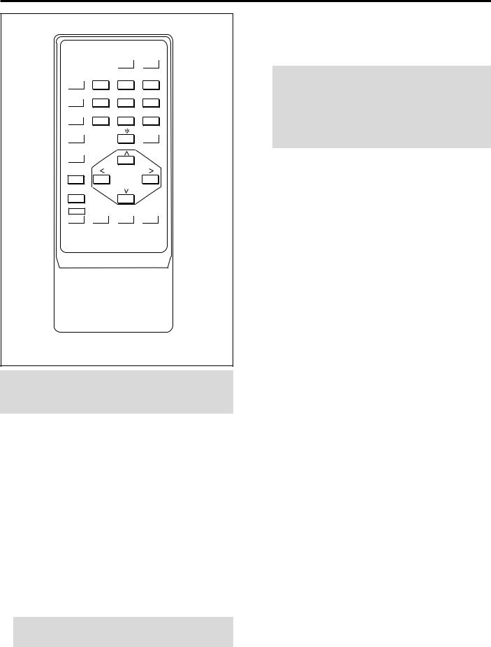
User Remote Control
RC-6320
NOTE: The full function remote control is designed for setup adjustment. Use the user remote control for normal operation.
1POWER Buttons (ON/OFF)
Press the ON button to turn the projector on when the projector is in the standby condition (STANDBY and RC READY indicators lit). Press the OFF button to return the projector to the standby condition.
2OPERATE Button
Press to display the “OPERATE” menu.
3PICTURE MUTE Button
Press to mute the picture. Press again to display the picture.
4SOUND MUTE Button
Press to mute the sound. Press again to return the sound.
NOTE: This works only with the ISS-6020/ISS-6020G Switcher.
5DISPLAY Button
Press to turn on or off the on-screen display. Pressing with CTL eliminates the on-screen display; pressing with CTL again restores it.
NOTE: Even if the on-screen display may be turned off with pressing CTL and DISPLAY, any adjustment will still change the projector’s memory settings. This mode is available even when an input is switched to another or the power is turned off using the POWER OFF button on the remote control.
6STATIC Button
Press to enter the STATIC mode. You can adjust the static convergence.
7R and B Buttons
Turn each CRT beam on and off separately. When using with the CTL button, you can select the CRT to be adjusted during static convergence.
8CTL Button
Used in conjunction with other buttons, similar to a shift key on a computer.
9NORMAL Button
Returns the standard level for each signal. When pressed once, the confirmation message will be displayed. When “YES” is selected and ENTER is pressed, the data will be returned to the standard level. While holding down the CTL button, press the NORMAL button to display the “LOAD/CANCEL” menu to select either LOAD (last stored level) or CANCEL (data cancelled).
0INPUT Buttons
Select menus and switches input signals.
ACAPTION Button
Press to display the CLOSED CAPTION menu.
BCURSOR Buttons
Used for increasing and decreasing control levels, cursor movement and convergence adjustments.
CEND Button
Ends the adjustment mode.
DENTER Button
Executes menu selection and switches to selected input.
8
PART NAMES AND FUNCTIONS
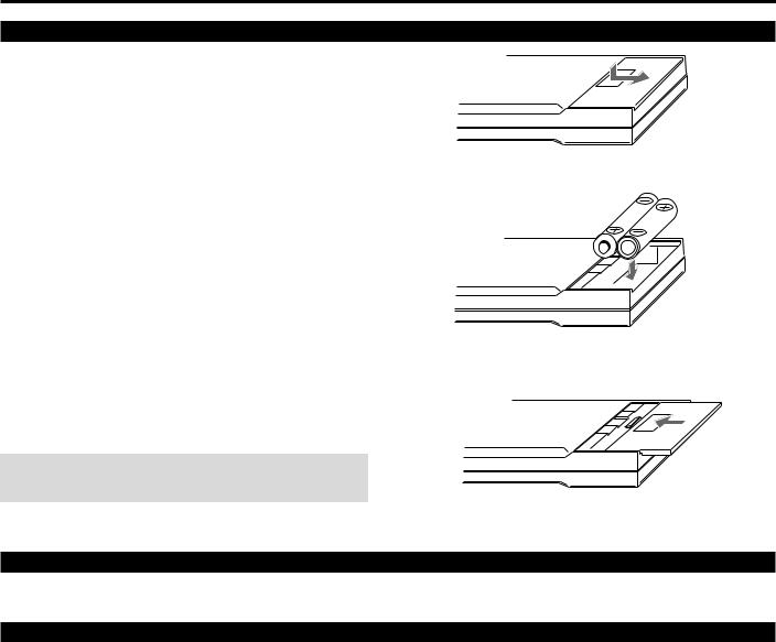
Battery installation and replacement
User remote control (RC-6320)
1
2 Install the two new batteries, making sure that their polarity matches the , . diagrams inside the battery compartment. Incorrect polarity could damage the unit.
3 Close the battery compartment cover.
NOTE: The remote control is powered by two alkaline 1.5V
AA batteries.
Remote control cautions
Use the remote control within a distance of about 7m (23 ft.) and at 30 degrees angle left and right.
Handling remote control and batteries
•Do not drop or mishandle the remote.
•Do not get the remote wet. If the remote gets wet, wipe it dry immediately.
•Avoid heat and humidity.
•When not using the remote for a long period, remove the batteries.
•Do not use new and old batteries together, or use different types together.
•Do not take apart the batteries, heat them, or throw them into a fire.
9

1234512345123451234512345 66666 EXAMPLES OF CONNECTIONS. 123456
CAUTIONS ON CONNECTIONS:
•Unplug the projector and other equipment from the AC supply before making connections.
•Make sure that the plug of the power cord is properly connected to the power outlet. A loose connection may cause hum or noise.
• Confirm your connection layout with the user’s manual accompanying the equipment to be connected with the ISS- 6020/ISS-6020G Switcher.
When Used in Stand Alone Operation
Components with RGB and H/V SYNC outputs such as a personal computer
|
|
|
|
|
|
|
|
|
|
INPUT SELECT |
|
POWER |
|
|
|
|
|
|
|
|
|
INDICATOR |
ON/OFF |
INPUT |
SELECT |
ENTER |
I |
|
|
|
|
|
|
|
|
|
|
|
CUT |
|
IN |
ACAT OUT |
R(VIDEO) |
G(Y) |
B(C) |
H/HV |
V |
S-VIDEO |
VIDEO |
OPTION |
REMOTE1 |
REMOTE2 |
|
||
VCR with S-Video outputs |
VCR or Video disc player |
External Control
NOTE: This projector does not have built-in speakers.
• Make sure that the STANDALONE mode is selected from the CONNECT CONDITION menu. Contact your dealer for the information in detail.
10
EXAMPLES OF CONNECTIONS
When Used with One Switcher (ISS-6020/ISS-6020G)
Up to 10 input signals can be accepted when the projector is connected to one Switcher. Using the projector with the Switcher
allows easy adjustment and signal selection.
INPUT C
INPUT B
INPUT A
|
|
|
|
|
|
|
|
|
|
INPUT SELECT |
POWER |
||
|
|
|
|
|
|
|
|
INDICATOR |
ON/OFF |
INPUT |
SELECT |
ENTER |
I |
|
|
|
|
|
|
|
|
|
|
|
CUT |
|
IN |
ACAT OUT |
R(VIDEO) |
G(Y) |
B(C) |
H/HV |
V |
S-VIDEO |
VIDEO |
OPTION |
REMOTE1 |
REMOTE2 |
|
||
To INPUT A (RGB,
H/V,V inputs)
5BNC-5BNC coaxial cable (separate sync) (recommended)
From R, G, B, H/V on separate H and
V. on the RGB OUTPUT module
3BNC-3BNC cable (sync on green) 4BNC-4BNC cable (composite)
To REMOTE1
Optional control cable 15p-15p (CTL-6010)
From REMOTE 1 Terminal on the
SYSTEM CONTROL module
The Switcher ISS-6020/ISS-6020G
Audio equipment
VCR |
Personal computer |
•Make sure that the SW1 LEVEL mode is selected from the CONNECT CONDITION menu. Contact your dealer for the information in detail.
•For more information on the Switcher, refer to the user’s manual accompanying the ISS-6020/ISS-6020G Switcher.
•All cables mentioned above are optional.
11
 Loading...