

Page 1

be certain.
m
MTS Insight™ Material Testing Systems
Product Information
1kN–300kN
100-146-666 G
Page 2

Copyright information © 2006 - 2010 MTS Systems Corporation. All rights reserved.
Trademark information MTS and TestWorks are registered trademarks of MTS Systems Corporation;
MTS Insight is a trademark of MTS Systems Corporation within the United
States. These trademarks may be protected in other countries.
Publication information
MANUAL PART NUMBER PUBLICATION DATE
100-146-666 A January 2006
(build 041306)
100-146-666 B June 2006
100-146-666 C June 2006
(build 081006)
100-146-666 D December 2006
(build 051007)
100-146-666 E May 2007
100-146-666 F April 2009
100-146-666 G March 2010
Page 3

Contents
Technical Support 5
How to Get Technical Support 5
Before You Contact MTS 6
If You Contact MTS by Phone 7
Problem Submittal Form in MTS Manuals 8
Preface 9
Before You Begin 9
Conventions 10
Documentation Conventions 10
Introduction 13
About This Manual 13
Description 14
Specifications 17
General Specifications 17
Model Specifications 18
Dimensions 22
Crosshead Detail 23
Baseplate Detail 24
Safety 27
General Safety Practices 27
Safety Practices Before System Operation 28
Safety Practices While the System Is in Operation 31
Hazard Labels 32
Installation 35
Moving Single-Column Frames 36
Moving Double-Column Frames 38
Machine Location and Ventilation 39
MTS Insight™ Material Testing System Contents
3
Page 4

Controller Connections 40
Connecting the Main Power 40
Transformer Requirements for MTS Insight 150, 200 and 300 Machines 44
Installing Cables 46
Controller Connectors 46
Operation 53
Main Power Switch (I/O) and E-Stop 54
Travel Limit Switches (Physical Limits) 55
Crush Zone Hazards 57
Fixture Mounting 58
Load Cell Mounting 59
Handset Control 63
Maintenance 65
Routine Maintenance Overview Checklist 66
Appendix 69
Additional Digital I/O Information 69
Electromechanical Load Unit Maintenance and Service Logs 71
8 Hours/Daily 72
40 Hours/Weekly 73
2000 Hours 74
2000 Hours 75
2000 Hours 76
4
Contents
MTS Insight™ Material Testing System
Page 5

Technical Support
How to Get Technical Support
Start with your
manuals
Technical support
methods
The manuals supplied by MTS provide most of the information you need to use
and maintain your equipment. If your equipment includes software, look for
online help and README files that contain additional product inform ation.
If you cannot find answers to your technical questions from these sources, you
can use the Internet, e-mail, telephone, or fax to contact MTS for assistance.
MTS provides a full range of support services after your system is installed. If
you have any questions about a system or product, contact Technical Support in
one of the following ways.
www.mts.com The web site provides access to our technical support staff by means of an
onlineform:
www.mts.com > Contact MTS > Service & Technical Support button
E-mail tech.support@mts.com
Telephone MTS Call Center 800-328-2255
Weekdays 7:00 A.M. to 5:00 P.M., Central Time
Fax 952-937-4515
Please include “Technical Support” in the subject line.
Outside the U.S. For technical support outside the United States, contact your local sales and
service office. For a list of worldwide sales and service locations and contact
information, use the Global MTS link at the MTS web site:
www.mts.com > Global MTS > (choose your region in the right-hand
column) > (choose the location closest to you)
MTS Insight™ Material Testing System Technical Support
5
Page 6

Before You Contact MTS
MTS can help you more efficiently if you have the following information
available when you contact us for support.
Know your site
number and system
number
Know information from
prior technical
The site number contains your company number and identifies your equipment
type (such as material testing or simulation). The number is typically written on a
label on your equipment before the system leaves MTS. If you do not know your
MTS site number, contact your sales engineer.
Example site number: 571167
When you have more than one MTS system, the system job number identifies
your system. You can find your job numb er in your order paperwork.
Example system number: US1.42460
If you have contacted MTS about this problem before, we can recall your file
based on the:
assistance
• MTS notification number
• Name of the person who helped you
Identify the problem Describe the problem and know the answers to the following questions:
• How long and how often has the problem occurred?
• Can you reproduce the problem?
• Were any hardware or software changes made to the system before the
problem started?
Know relevant
computer information
• What are the equipment model numbers?
• What is the controller model (if applicable)?
• What is the system configuration?
For a computer problem, have the following information available:
• Manufacturer’s name and model number
• Operating software type and service patch information
• Amount of system memory
• Amount of free space on the hard drive where the application resides
• Current status of hard-drive fragmentation
• Connection status to a corporate network
Technical Support
6
MTS Insight™ Material Testing System
Page 7

Know relevant
For software application problems, have the following information available:
software information
• The software application’s name, version number, build number, and (if
available) software patch number. This information can typically be found
in the About selection in the Help menu.
• The names of other applications on your computer, such as:
– Anti-virus software
– Screen savers
– Keyboard enhancers
– Print spoolers
– Messaging applications
If You Contact MTS by Phone
A Call Center agent registers your call before connecting you with a technical
support specialist. The agent asks you for your:
• Site number
• Name
• Company name
• Company address
• Phone number where you can be reached
If your issue has a notification number, please provide that number. A new issue
will be assigned a unique notification number.
Identify system type To enable the Call Center agent to connect you with the most qualified technical
support specialist available, identify your system as one of the following types:
• Electromechanical material test system
• Hydromechanical material test system
• Vehicle test system
• Vehicle component test system
• Aero test system
Be prepared to
Prepare to perform troubleshooting while on the phone:
troubleshoot
• Call from a telephone close to the system so that you can implement
suggestions made over the phone.
• Have the original operating and application software media available.
• If you are not familiar with all aspects of the equipment operation, have an
experienced user nearby to assist you.
MTS Insight™ Material Testing System Technical Support
7
Page 8

Write down relevant
In case Technical Support must call you:
information
• Verify the notification number.
• Record the name of the person who helped you.
• Write down any specific instructions.
After you call MTS logs and tracks all calls to ensure that you receive assistance for your
problem or request. If you have questions about the status of your problem or
have additional information to report, please contact Technical Support again and
provide your original notification number.
Problem Submittal Form in MTS Manuals
Use the Problem Submittal Form to communicate problems with your software,
hardware, manuals, or service that are not resolved to your satisfaction through
the technical support process. The form includes check boxes that allow you to
indicate the urgency of your problem and your expectation of an acceptable
response time. We guarantee a timely response—your feedback is important to
us.
Access the Problem Submittal Form:
• In the back of many MTS manuals (postage paid form to be mailed to MTS)
• www.mts.com > Contact Us > Problem Submittal Form button (electronic
form to be e-mailed to MTS)
Technical Support
8
MTS Insight™ Material Testing System
Page 9

Preface
Before You Begin
Safety first! Before you use your MTS product or system, read and understand the Safety
manual and any other safety information provided with your system. Improper
installation, operation, or maintenance can result in hazardous conditions that can
cause severe personal injury or death, or damage to your equipment and
specimen. Again, read and understand the safety information provided with your
system before you continue. It is very important that you remain aware of
hazards that apply to your system.
Other MTS manuals In addition to this manual, you may receive additional manuals in paper or
electronic form.
You may also receive an MTS System Documentation CD. It contains an
electronic copy of the manuals that pertain to your test system, such as:
• Hydraulic and mechanical component manuals
• Assembly drawings
• Parts lists
• Operation manual
• Preventive maintenance manual
Controller and application software manuals are typically included on the
software CD distribution disc(s).
MTS Insight™ Material Testing System Preface
9
Page 10

Conventions
DANGER
WARNING
CAUTION
Conventions
Documentation Conventions
The following paragraphs describe some of the conventions that are used in your
MTS manuals.
Hazard conventions Hazard notices may be embedded in this manual. These notices contain safety
information that is specific to the activity to be performed. Hazard notices
immediately precede the step or procedure that may lead to an associated hazard.
Read all hazard notices carefully and follow all directions and recommendations.
Three different levels of hazard notices may appear in your manuals. Following
are examples of all three levels.
Note For general safety information, see the safety information provided with
your system.
Danger notices indicate the presence of a hazard with a high level of risk which,
if ignored, will result in death, severe personal injury, or substantial property
damage.
Warning notices indicate the presence of a hazard with a medium level of risk
which, if ignored, can result in death, severe personal injury, or substantial
property damage.
Caution notices indicate the presence of a hazard with a low level of risk which,
if ignored, could cause moderate or minor personal injury or equipment damage,
or could endanger test integrity.
Notes Notes provide additional information about operating your system or highlight
easily overlooked items. For example:
Note Resources that are put back on the hardware lists show up at the end of
the list.
Special terms The first occurrence of special terms is shown in italics.
Illustrations Illustrations appear in this manual to clarify text. They are examples only and do
not necessarily represent your actual system configuration, test application, or
software.
Electronic manual
conventions
This manual is available as an electronic document in the Portable Document
File (PDF) format. It can be viewed on any computer that has Adobe Acrobat
Reader installed.
10
Preface
MTS Insight™ Material Testing System
Page 11

Conventions
Hypertext links The electronic document has many hypertext links displayed in a blue font. All
blue words in the body text, along with all contents entries and index page
numbers, are hypertext links. When you click a hypertext link, the application
jumps to the corresponding topic.
MTS Insight™ Material Testing System Preface
11
Page 12

Conventions
12
Preface
MTS Insight™ Material Testing System
Page 13

Introduction
About This Manual
Purpose This manual provides detailed information about the MTS Insight Material
Summary This manual includes the following sections.
Introduction This section reviews the MTS Insight material testing system models, gives you a
Testing Systems. The information includes an overview of all the models
available, installation, operation, and maintenance.
The MTS Insight product series is the latest generation of electromechanical
material testing equipment from MTS. The purpose of this manual is to help you
understand your testing system, its capabilities, and operating requirements. This
manual provides technical information for all MTS Insight material testing
frames; from the lowest force model (1 kN), to the highest (300 kN). Read each
section carefully and refer to the manual whenever you need assistance.
description of a typical frame, and lists the environmental specifications. This
section also provides the technical frame specifications of each MTS Insight
frame model and line drawings of the crosshead and baseplate details.
Installation This section gives you specific instructions for properly moving MTS Insight
frames, cable installation, and line drawings of the basic controller.
Operation This section provides a graphic of the manual handset control and handset
functions. Other areas such as travel limit switches and fixture and load cell
mounting are reviewed.
Maintenance This section gives you a complete guide to the maintenance schedule for all MTS
Insight frames.
Inappropriate use Before you attempt to use the MTS Insight Material Testing System, read and
understand your manual that accompanies this product. Improper installation or
operation of this product can result in hazardous conditions that can cause severe
personal injury or death, and damage your equipment and specimen.
Contents Description 14
Specifications 17
Model Specifications 18
Crosshead Detail 23
Baseplate Detail 24
MTS Insight™ Material Testing System Introduction
13
Page 14
Description
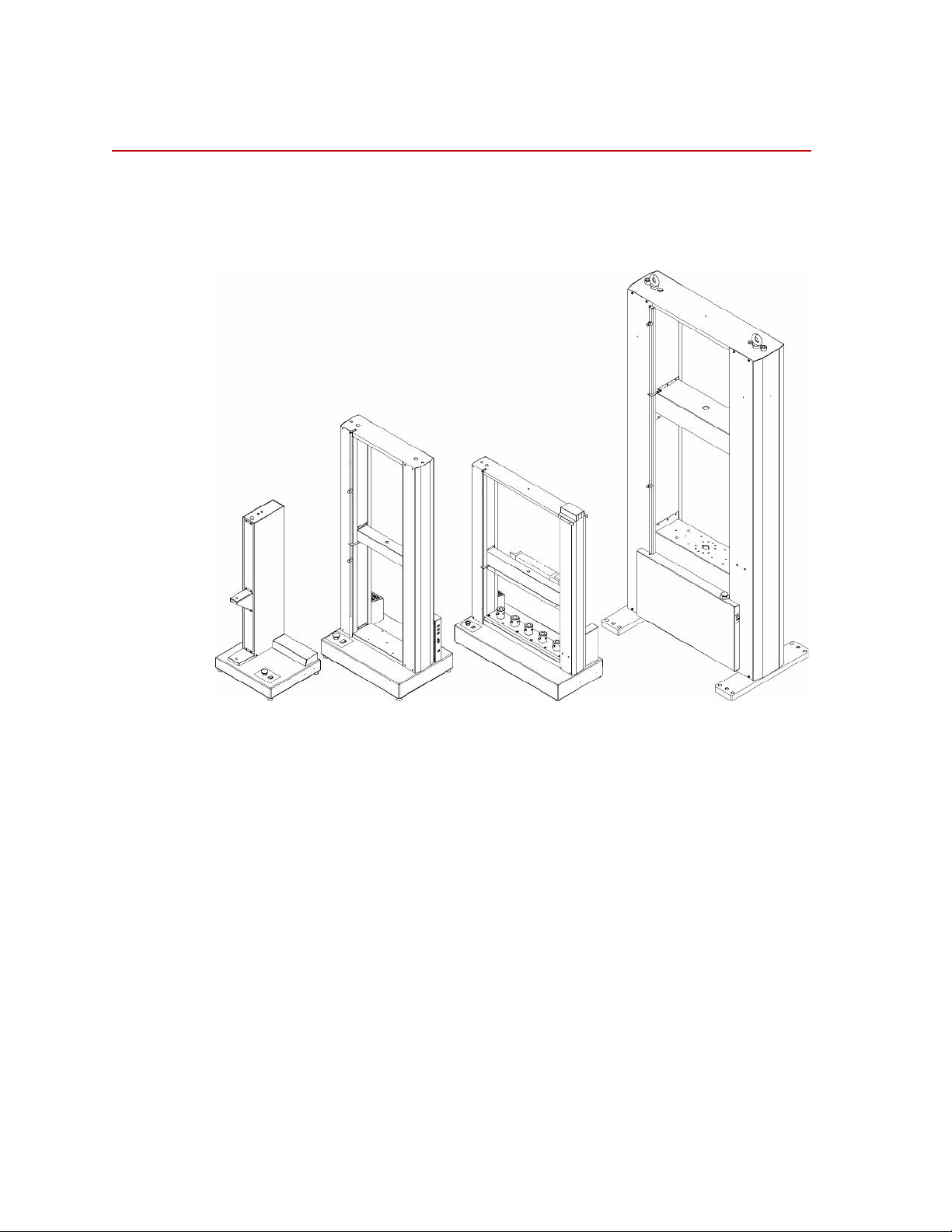
Low Capacity Mid-Capacity High-CapacityMultihead
Description
Every MTS Insight material testing system is comprised of a load frame,
electronic frame controller, and TestWorks software. The following figure shows
the external features of the various MTS Insight load frames.
14
Introduction
The personal computer is also an integral part of the system. It runs TestWorks
software which provides full machine control, data acquisition and management,
and advanced data analysis and presentation. MTS has minimized the amount of
custom electronics required for your system, thereby making it flexible and
reliable. This is done by connecting the frame and the computer via standard
USB 2.0 connectors.
The load frame has a rectangular shape and includes a base unit and one or two
vertical columns. The two column models have a fixed upper transverse member.
The moving crosshead is driven by precision ball screws on the load frame. The
crosshead is coupled to the ball screw(s) with high-strength, precision ball nuts
and rides on the ball bearings. This configuration is very efficient in minimizing
friction and wear. The ball screws are anti-backlash. This feature removes the
backlash so that position can be measured with increased accuracy over
nonpreloaded ball screws.
The screws are driven by a series of pulleys and belts which in turn are driven by
a precision DC servo motor on the MTS Insight 1 through MTS Insight 50
models and an AC brushless motor on the higher force models. The ball screw is
connected to an optical encoder for precise position and velocity control.
MTS Insight™ Material Testing System
Page 15

Frame controller The frame controller is responsible for the following:
• Provides main data and signal processing power
• Detects the activation of limit switches
• Provides the interface between the software (computer) and the frame
• Provides digital servo control—for speed and position accuracy
• Responsible for self-ID load cell and frame
• Handset interface
• Programmable, 1000 Hz maximum, data acquisition rate
• Management of frame power
Description
MTS Insight™ Material Testing System Introduction
15
Page 16

Description
Software TestWorks 4 is a versatile software program offering you a host of features that
will make the material testing process fast and easy to use. The software has
various method templates available. The method templates in the General Testing
Package provide a starting point in configuring test methods that conform with
your testing needs. The General Testing Package is separated into 4 specific
testing categories.
• MTS Tensile
• MTS Compression
• MTS Flex
• MTS Peel-Tear
Many additional features can be purchased to meet your company’s specific
needs. Some of these features might already be part of the system you ordered, or
they can be added to your system as your requirements change. Refer to the
TestWorks manual for additional information.
16
Introduction
MTS Insight™ Material Testing System
Page 17

Specifications
This section provides general specifications for the MTS Insight Material Testing
System frames and illustrations of the crosshead and baseplate threaded hole
patterns for mounting fixtures.
Note At the time of this printing, some specifications have not been tested and
General Specifications
The following specifications are for all MTS Insight frames. Specifications for
the specific models and in the following tables.
Parameter Specification
Environmental
Specifications
calculated specifications are provided in the following tables.
Consequently, specifications are subject to change without notice.
Contact MTS for verification if critical specifications.
For indoor use only
Power
Temperature
Relative humidity
Altitude
Insulation over voltage
Pollution degree
5 to 40 °C
10 to 85%, noncondensing
For use at altitudes up to 2000 m
(6500 ft)
Category II
2
MTS Insight™ Material Testing System Introduction
17
Page 18

Specifications
MTS MTS
MTS
MTS
MTS MTS Insight
Insight 1 Insight 2
Insight 2
Insight 5
Insight 5
Model
High Speed
Column Configuration Single Single Double Single Double
Force Capacity 1 kN 2 kN 2 kN 5 kN 5 kN
(225 lbf) (450 lbf) (450 lbf) (1125 lbf) (1125 lbf)
Vertical T est Space
Crosshead Travel
Standard Length 750 mm 750 mm NA 750 mm 1100 mm
(29.5 in) (29.5 in) (29.5 in) (43 in)
Extended Length 1004 mm 1004 mm 1400 mm 1004 mm 1400 mm
(39.5 in) (39.5 in) (55 in) (39.5 in) (55 in)
Maximum Test Speed 1500 mm/min 1000 mm/min 2540 mm/min 500 mm/min 1000 mm/min
(59 in/min) (39 in/min) (100 in/min) (20 in/min) (39 in/min)
Minimum Test Speed 0.001 mm/min 0.001 mm/min 0.003 mm/min 0.001 mm/min 0.001 mm/min
(0.00004 in/min) (0.00004 in/min) (0.00012 in/min) (0.00004 in/min) (0.00004 in/min)
Height
Standard Length 1140 mm 1140
mm NA 1140 mm 1600 mm
(45 in) (45 in) (45 in) (63 in)
Extended Length 1394 mm 1394 mm 1900 mm 1394 mm 1900 mm
(55 in) (55 in) (74.75 in) (55 in) (74.75 in)
Width 490 mm 490 mm 650 mm 490 mm 650 mm
(19 in) (19 in) (26 in) (19 in) (26 in)
Depth 450 mm 450 mm 450 mm 450 mm 450 mm
(18 in) (18 in) (18 in) (18 in) (18 in)
Weight
Standard Length 50 kg 50
kg NA 50 kg 115 kg
(110 lb) (110 lb) (110 lb) (255 lb)
Extended Length 55 kg 55 kg 123 kg 55 kg 123 kg
(119 lb) (119 lb) (261 lb) (119 lb) (261 lb)
Clearance from Loading 100 mm 100 mm NA 100 mm N/A
Axis to Column Cover (3.9 in) (3.9 in) (3.9 in)
Space Between Columns N/A N/A 450 mm N/A 405 mm
(15.9 lb) (15.9 in)
Power Requirements
Power Supply
120 or 120
or 120 or 120 or 120 or
230 VAC 230 VAC 230 VAC 230 VAC 230 VAC
(single phase) (single phase) (single phase) (single phase) (single phase)
Model Specifications
Low Capacity
18
Introduction
MTS Insight™ Material Testing System
Page 19

MTS Insight
Model
Column Configuration
Force Capacity
Vertical T est Space
Crosshead Travel
Standard Length
Extended Length
Maximum Test Speed
Minimum Test Speed
Height
Standard Length
Extended
Length
Specifications
Mid-Capacity
MTS MTS
Insight 10 Insight 30
Double Double Double Double Double
10 kN 30 kN 30 kN 50 kN 50 kN
(2250 lbf) (6750 lbf) (6750 lbf) (11250 lbf) (11250 lbf)
1100 mm 1100 mm NA 1100 mm 1050 mm
(43 in) (43 in) (43 in) (41 in)
1400 mm 1400 mm 1350 mm 1400 mm NA
(55 in) (54.75 in) (53 in) (54.75 in)
1000 mm/min 500 mm/min 500 mm/min 500 mm/min 500 mm/min
(39 in/min) (20 in/min) (20 in/min) (20 in/min) (20 in/min)
0.001 mm/min 0.001 mm/min 0.001 mm/min 0.001 mm/min 0.001 mm/min
(0.00004 in/min) (0.00004 in/min) (0.00004 in/min) (0.00004 in/min) (0.00004 in/min)
1600 mm 1613 mm NA 1613 mm 1629 mm
(63 in) (64 in) (64 in) (64.1 in)
1900 mm 1394 mm 1900 mm 1394 mm NA
74.75 in) (75.75 in) (76 in) (75.75
MTS
Insight 30
Wide
MTS
Insight 50
in)
MTS
Insight 50
Wide
Width
Depth
Weight
Standard Length
Extended Length
Clearance from Loading
Axis to Column Cover
Space Between Columns
Power Requirements
Power Supply
650 mm 720 mm 1145 mm 720 mm 1145 mm
(26 in) (29 in) (45 in) (29 in) (45 in)
450 mm 500 mm 500 mm 500 mm 500 mm
(18 in) (20 in) (20 in) (20 in) (20 in)
115 kg 180 kg NA 180 kg 296 kg
(255 lb) (397 lb) (397 lb) (653 lb)
123 kg 191 kg 314 kg 191 kg NA
(261 lb) (422 lb) (692 lb) (422 lb)
N/A N/A NA N/A N/A
405 mm 405 mm 835 mm 405 mm 835 mm
(15.9 in) (15.9 in) (20 in) (15.9 in) (33 in)
120 or 120 or 120 or 120 or 120 or
230 V AC 230 VAC 230 VAC 230 VAC 230 VAC
(single phase) (single phase) (single phase) (single phase) (single phase)
MTS Insight™ Material Testing System Introduction
19
Page 20

Specifications
MTS MTS MTS MTS
Insight 100 Insight 150 Insight 200 Insight 300
Double Double Double Double
100 kN 150 kN 200 kN 300 kN
(22500 lbf) (33750 lbf) (45000 lbf) (67500 lbf)
1200 mm 1200 mm 1200 mm 1150 mm
(47.3 in) (47.3 in) (47.3 in) (45.3 in)
1600 mm 1600 mm 1600 mm 1550 mm
(63 in) (63 in) (63 in) (61 in)
500 mm/min 500 mm/min 500 mm/min 500 mm/min
(20 in/min) (20 in/min) (20 in/min) (20 in/min)
0.01 mm/min 0.01 mm/min 0.01 mm/min 0.01 mm/min
(0.0004 in/min) (0.0004 in/min) (0.0004 in/min) (0.0004 in/min)
2440 mm 2440 mm 2440 mm 2440 mm
(96 in) (96 in) (96 in) (96 in)
2840 mm 2840 mm 2840 mm 2840 mm
(112 in) (112 in) (112 in) (112 in)
1133 mm 1133 mm 1133 mm 1133 mm
(44.6 in) (44.6 in) (44.6 in) (44.6 in)
685 mm 685 mm 685 mm 685 mm
(27 in) (27 in) (27 in) (27 in)
750 kg 970 kg 970 kg 1050 kg
(1655 lb) (2140 lb) (2140 lb) (2315 lb)
787 kg 1029 kg 1029 kg 1116 kg
(1735 lb) (2270 lb) (2270 lb) (2460 lb)
N/A NA N/A N/A
650 mm 650
mm 650 mm 650 mm
(25.6 in) (25.6 in) (25.6 in) (25.6 in)
230 VAC 400 VAC 400 VAC 400 VAC
(single phase) (three phase) (three phase) (three phase)
MTS Insight
Model
Column Configuration
Force Capacity
Vertical T est Space
Crosshead Travel
Standard Length
Extended Length
Maximum Test Speed
Minimum Test Speed
Height
Standard Length
Extended Length
Width
Depth
Weight
Standard Length
Extended Length
Clearance from Loading
Axis to Column Cover
Space Between Columns
Power Requirements
Power Supply
High-Capacity
Specifications MTS Insight 50 Wide
Force Capacity 50 KN (11 250 lbf)
MTS Insight 50 W Multihead
Minimum Test Speed 0.001 mm/min. (0.00004 in./min.)
Maximum Test Speed 500 mm/min. (19.7 in./min.)
Force Capacity
@ max. test speed
Maximum Test Speed
@rated force capacity
25 KN (5625 lbf)
250 mm/min. (9.8 in./min.)
Introduction
20
MTS Insight™ Material Testing System
Page 21

MTS Insight 50 W Multihead
Crosshead Return Speed 500 mm/min. (20 in./min.)
Vertical Test Space
(crosshead travel)
Horizontal Test Space
(between baseplate adapter centerlines)
Position Resolution 0.001 mm (0.00004 in.)
Position Accuracy 0.01 mm (0.0004 in)
Speed Accuracy % of set speed
Motor Type Precision DC Servo Motor
Drive System Type DC 4 Quadrant Motor Drive
Position Measurement Optical Encoder
Ball Screw Type Anti-backlash
Guide Columns Two
Height/Width/Depth 1629 X 1145 X 500 mm
Weight 350 kg (772 lb)
Power 5/3 Amps
1016 mm (40 in.)
155.5 mm (6.125 in.)
±0.05
(64.1 X 45 X 20 in.)
120/220-240 Vac
50/60 Hz
Single phase
Specifications
MTS Insight™ Material Testing System Introduction
21
Page 22
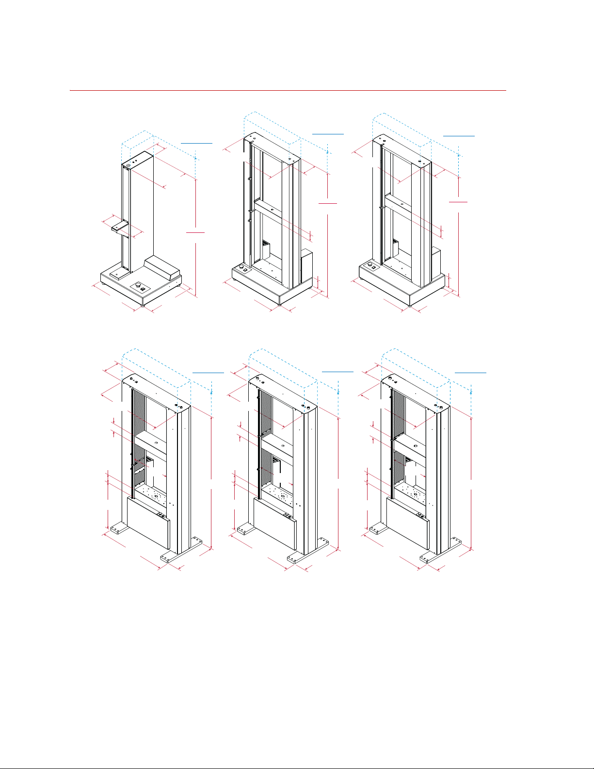
Specifications
450 mm
(18 in)
Standard
1140 mm
(45 in)
103 mm
(4.1 in)
134 mm
(5.3 in)
490 mm
(19 in)
269 mm
(10.6 in)
699 mm
(27.5 in)
Standard
1613 mm
(64 in)
155 mm
(6.1 in)
102 mm
(4 in)
500 mm
(20 in)
720 mm
(29 in)
155 mm
(6.1 in)
641 mm
(25.2 in)
Standard
1600 mm
(63 in)
155 mm
(6.1 in)
76 mm
(3 in)
450 mm
(18 in)
650 mm
(26 in)
125 mm
(4.9 in)
MTS Insight
Model 1, 2 and 5
MTS Insight
Model 5 and 10
MTS Insight
Model 30 and 50
100 mm
(3.9 in)
1130 mm
(44.5 in)
264 mm
(10.4 in)
650 mm
(25.6 in)
685 mm
(27 in)
1130 mm
(44.5 in)
650 mm
(25.6 in)
685 mm
(27 in)
1130 mm
(44.5 in)
264 mm
(10.4 in)
650 mm
(25.6 in)
685 mm
(27 in)
130 mm
(5.1 in)
140 mm
(5.5 in)
550 mm
(21.6 in)
1133 mm
(44.6 in)
2440 mm
(96 in)
152 mm
(6 in)
152 mm
(6 in)
550 mm
(21.6 in)
1133 mm
(44.6 in)
2440 mm
(96 in)
264 mm
(10.4 in)
178 mm
(7 in)
178 mm
(7 in)
550 mm
(21.6 in)
1133 mm
(44.6 in)
2440 mm
(96 in)
MTS Insight
Model 100
MTS Insight
Model 150 and 200
MTS Insight
Model 300
Extended Length
1394 mm
(55 in)
Extended Length
1900 mm
(74.75 in)
Extended Length
1913 mm
(75.75 in)
Extended Length
2840 mm
(112 in)
Extended Length
2840 mm
(112 in)
Extended Length
2840 mm
(112 in)
Dimensions
22
Introduction
MTS Insight™ Material Testing System
Page 23
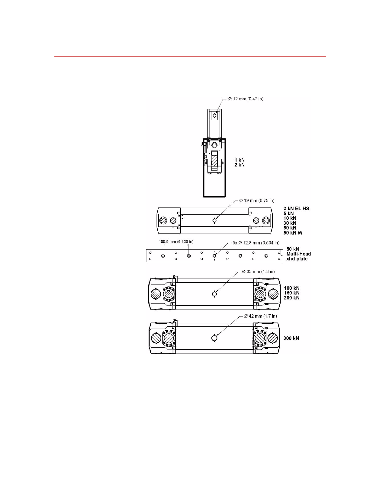
Crosshead Detail
Specifications
The crosshead has a single hole drilled through for mounting loadcells, alignment
fixtures, grips, and so forth.
MTS Insight™ Material Testing System Introduction
23
Page 24
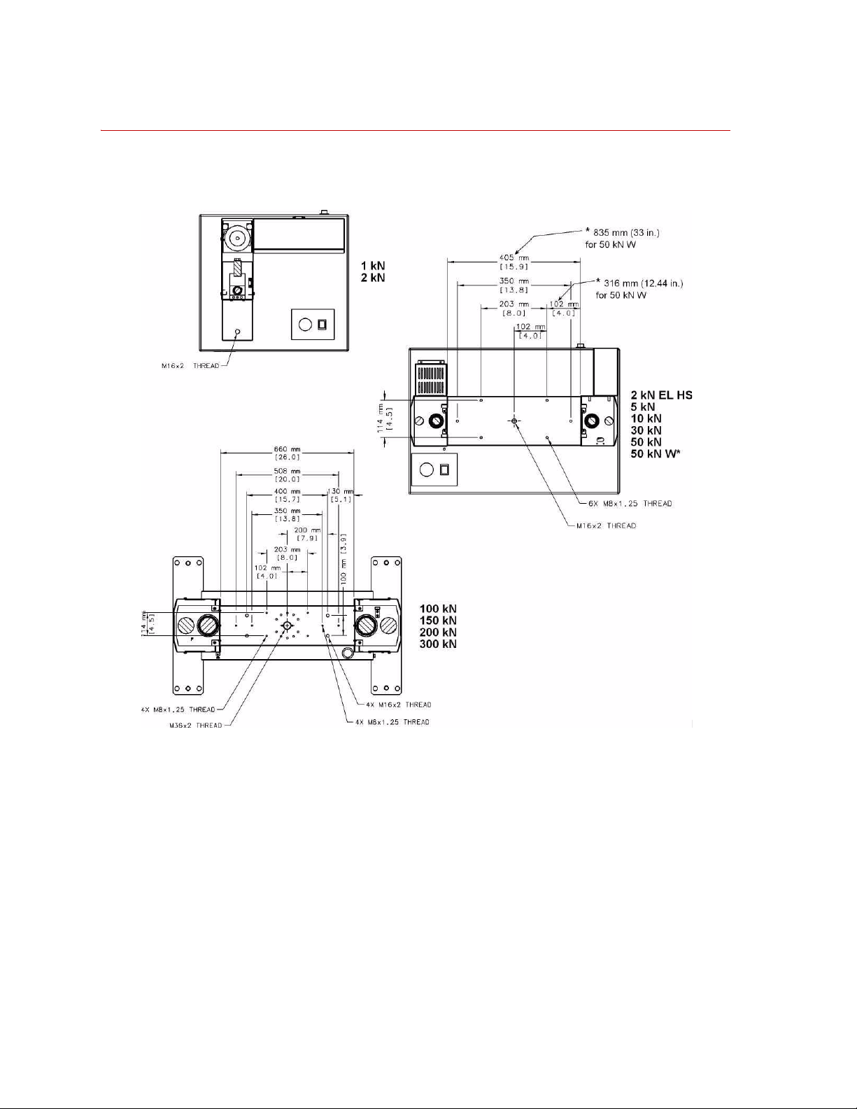
Specifications
Baseplate Detail
The baseplate has various patterns of threaded holes for mounting fixtures.
24
Introduction
MTS Insight™ Material Testing System
Page 25

50 kN W Multihead
Specifications
MTS Insight™ Material Testing System Introduction
25
Page 26

Specifications
Model Baseplate Thickness
mm in.
1 kN 19 0.7
2 kN 19 0.7
2 kN EL HS 25 1.0
5 kN 25 1.0
10 kN 25 1.0
30 kN 25 1.0
50 kN 25 1.0
50 kN W 50 2.0
50 kN W Multihead 50 2.0
100 kN 140 5.5
150 kN 152 6.0
200 kN 152 6.0
300 kN 178 7.0
26
Introduction
MTS Insight™ Material Testing System
Page 27

Safety
General Safety Practices
This section provides information about safety issues that pertain to
electromechanical systems in general. These issues include statements to the
intended use and foreseeable misuse of the system, the hazard zone, definition for
the graphical hazard labeling that is affixed to your product, and other (more
general) safety information that relates to the high-performance characteristics of
MTS electromechanical systems.
MTS test systems are designed to generate motions and forces and impart these
motions and forces into a test specimen.
When you prepare to operate the system and during system operation, ensure the
following:
• Do not use or allow personnel to operate the system who are not
• Do not disable safety components or features (including limit detectors,
experienced, trained, or educated in the inherent dangers associated with
high-performance electromechanical machines and who are not
experienced, trained, or educated with regard to the intended operation as it
applies to this test system.
light curtains, or proximity switches/detectors).
• Do not attempt to operate the system without appropriate personal safety
gear (for example, hearing, hand, and eye protection).
• Do not use specimens that are combustible, flammable, pressurized, or
explosive.
• Whenever possible, use tongs or similar device to handle specimens during
specimen installation.
• Do not use humans as specimens or allow humans to ride in or on the test
specimen or the test system for any purpose unless the system is man-rated
and all associated safety conditions are strictly enforced.
• Do not modify the system or replace system components using parts that are
not MTS component parts or effect repairs using parts or components that
are not manufactured to MTS specifications.
• Do not operate the system in an explosive atmosphere.
• Do not use the system in a test area where uncontrolled access to the test
system is allowed when the system is in operation.
If you have system related responsibilities (that is, if you are an operator, service
engineer, or maintenance person), you should study safety information carefully
before you attempt to perform any test system procedure.
Safety
27
Page 28

You should receive training on this system or a similar system to ensure a
thorough knowledge of your equipment and the safety issues that are associated
with its use. In addition, you should gain an understanding of system functions
by studying the other manuals supplied with your test system. Contact MTS for
information about the content and dates of training classes that are offered.
It is very important that you study the following safety information to ensure that
your facility procedures and the system’s operating environment do not
contribute to or result in a hazardous situation. Remember, you cannot eliminate
all the hazards associated with this system, so you must learn and remain aware
of the hazards that apply to your system at all times. Use these safety guidelines
to help learn and identify hazards so that you can establish appropriate training
and operating procedures and acquire appropriate safety equipment (such as
gloves, goggles, and hearing protection).
Each test system operates within a unique environment which includes the
following known variables:
• Facility variables (facility variables include the structure, atmosphere, and
utilities)
• Unauthorized customer modifications to the equipment
• Operator experience and specialization
• Test specimens
Because of these variables (and the possibility of others), your system can
operate under unforeseen circumstances that can result in an operating
environment with unknown hazards.
Improper installation, operation, or maintenance of your system can result in
hazardous conditions that can cause death, personal injury, or damage to the
equipment or to the specimen. Common sense and a thorough knowledge of the
system’s operating capabilities can help to determine an appropriate and safe
approach to its operation.
Safety Practices Before System Operation
Before you apply power to the test system, review and complete all of the safety
practices that are applicable to your system. The goal, by doing this, is to
improve the safety awareness of all personnel involved with the system and to
maintain, through visual inspections, the integrity of specific system
components.
Read all manuals Study the contents of this manual and the other manuals provided with your
system before attempting to perform any system function for the first time.
Procedures that seem relatively simple or intuitively obvious can require a
complete understanding of system operation to avoid unsafe or dangerous
situations.
Locate and read
hazard placards/labels
Find, read, and follow the hazard placard instructions located on the equipment.
These placards are placed strategically on the equipment to call attention to areas
such as known crush points and electrical voltage hazards.
28
Safety
Page 29

Locate Lockout/tagout
points
Know where the lockout/tagout point is for all of the supply energies associated
with your system. This includes the hydraulic, pneumatic, electric, and water
supplies (as appropriate) for your system to ensure that the system is isolated
from these energies when required.
Know facility safe
procedures
Locate Emergency
Stop buttons
Most facilities have internal procedures and rules regarding safe practices within
the facility. Be aware of these safe practices and incorporate them into your daily
operation of the system.
Know the location of all the system Emergency Stop buttons so that you can
stop the system quickly in an emergency . Ensure that an Emergency Stop button
is located within 2 meters (6 feet) of the operator at all times.
Know controls Before you operate the system for the first time, make a trial run through the
operating procedures with the power off. Locate all hardware and software
controls and know what their functions are and what adjustments they require. If
any control function or operating adjustment is not clear, review the applicable
information until you understand it thoroughly.
Have first aid available Accidents can happen even when you are careful. Arrange your operator
schedules so that a properly trained person is always close by to render first aid.
In addition, ensure that local emergency contact information is posted clearly and
in sight of the system operator.
Know potential crush
and pinch points
Know electrical
hazards
Be aware of potential crush and pinch points on your system and keep personnel
and equipment clear of these areas.
When the system electrical power is turned on, minimize the potential for
electrical shock hazards. Wear clothing and use tools that are properly insulated
for electrical work. Avoid contact with exposed wiring or switch con tacts.
Whenever possible, turn off electrical power when you work on or in proximity
to any electrical system component. Observe the same precautions as those given
for any other high-voltage machinery.
Keep bystanders
safely away
Keep bystanders at a safe distance from all equipment. Never allow bystanders to
touch specimens or equipment while the test is running.
Wear proper clothing Do not wear neckties, shop aprons, loose clothing or jewelry, or long hair that
could get caught in equipment and result in an injury. Remove loose clothing or
jewelry and restrain long hair.
Remove flammable
fluids from test
specimen
Check bolt ratings and
torques
Remove flammable fluids from their containers or from components before you
install the container or component in a test system. If desired, you can replace the
flammable fluid with a non-flammable fluid to maintain the proper proportion of
weight and balance.
To ensure a reliable product, fasteners (such as bolts and tie rods) used in MTSmanufactured systems are torqued to specific requirements. Overtorquing or
undertorquing a fastener can create a hazardous situation due to the high forces
and pressures present in MTS test systems.
Safety
29
Page 30

On rare occasions, a fastener can fail even when it is correctly installed. Failure
usually occurs during torquing, but it can occur several days later. Failure of a
fastener can result in a high velocity projectile. Therefore, it is a good practice to
avoid stationing personnel in line with or below assemblies that co ntai n large or
long fasteners.
Practice good
housekeeping
Protect hoses and
cables
Keep the floors in the work area clean. Do not leave tools, fixtures, or other items
not specific to the test, lying about on the floor, system, or decking.
Protect electrical cables from excessive temperatures that can cause the cables to
harden and eventually fail. Ensure that all cables have appropriate strain relief
devices installed at the cable and near the connector plug. Do not use the
connector plug as a strain relief.
Protect all system hoses and cables from sharp or abrasive objects that can cause
the hose or cable to fail. Never walk on hoses or cables or move heavy objects
over them. Consider system layout and route hoses and cables away from areas
that expose them to possible damage.
When removing hydraulic hoses for equipment repair or changing testing
components (for example, hydraulic grips), make sure to cap the hose ends to
avoid spilling hydraulic fluid.
Record changes If you change any operating procedure, write the change and the date of the
change in the appropriate manual.
Provide test area
guards
Do not disable safety
devices
Use protective guards such as cages, enclosures, and special laboratory layouts
when you work with hazardous test specimens (for example, brittle or
fragmenting materials or materials that are internally pressurized).
Your system might have active or passive safety devices installed to prevent
system operation if the device indicates an unsafe condition. Do not disable such
devices as it can result in unexpected system motion.
Use appropriately
sized fuses
Provide adequate
lighting
Provide means to
access out-of-reach
components
Ensure equipment is
secure
Safety
30
Whenever you replace fuses for the system or supply, ensure that you use a fuse
that is appropriately sized and correctly installed. Undersized or oversized fuses
can result in cables that overheat and fuses that explode. Either instance creates a
fire hazard.
Ensure adequate lighting to minimize the chance of operation errors, equipment
damage, and personal injury. You need to see what you are doing.
Make sure you can access system components that might be out of reach while
standing on the floor. For example ladders or scaffolding might be required to
reach load cell connectors on tall load units.
Make sure the equipment is secure or provide vibration isolation. Some testing
can be performed at resonant frequencies that might cause the equipment to
vibrate and move during testing.
Page 31

Safety Practices While the System Is in Operation
Wear appropriate
personal protection
Provide test area
guards
Specimen temperature
changes
Handle chemicals
safely
Wear eye protection when you work with electromechanical testing machines,
breakable specimens, or when anything characteristic to the specimen could
break apart.
W ear ear protection when you work near electric motors, pumps, or other devices
that generate high noise levels. Some systems can create sound pressure levels
that exceed 70 dbA during operation.
W ear appropriate personal protection equipment (gloves, boots, suits, respirators)
whenever you work with fluids, chemicals, or powders that can irritate or harm
the skin, respiratory system, or eyes.
Use protective guards such as cages, enclosures, and special laboratory layouts
when you work with hazardous test specimens (for example, brittle or
fragmenting materials or materials that are internally pressurized).
During cyclic testing, the specimen temperature can become hot enough to cause
burns. Wear personal protection equipment (gloves) when handling specimens.
Whenever you use or handle chemicals (for example, cleaning fluids, hydraulic
fluid, batteries, contaminated parts, electrical fluids, and maintenance waste),
refer to the appropriate MSDS documentation for that material and determine the
appropriate measures and equipment required to handle and use the chemical
safely. Ensure that the chemical is disposed of appropriately.
Know system
interlocks
Interlock devices should always be used and properly adjusted. Interlock devices
are designed to minimize the chance of accidental damage to the test specimen or
the equipment. Test all interlock devices for proper operation immediately before
a test. Do not disable or bypass any interlock devices as doing so could allow
crosshead movement regardless of the true interlock condition. The Reset/
Override button is a software function that can be used to temporarily override
an interlock while attempting to start and gain control of the system.
Know system limits Never rely on system limits such as mechanical limits or software limits to
protect you or any personnel. System limits are designed to minimize the chance
of accidental damage to test specimens or to equipment. T est all limits for proper
operation immediately before a test. Always use these limits and adjust them
properly.
Do not disturb sensors Do not bump, wiggle, adjust, disconnect, or otherwise disturb a sensor (such as
an accelerometer or extensometer) or its connecting cable when power is applied.
Ensure secure cables Do not change any cable connections when electrical power is applied. If you
attempt to change a cable connection while the system is in operation, an open
control loop condition can result. An open control loop condition can cause a
rapid, unexpected system response which can result in severe personal injury,
death, or damage to equipment. Also, ensure that all cables are connected after
you make any changes in the system configuration.
Safety
31
Page 32

Stay alert A void long periods of work without adequate rest. In addition, avoid long periods
Phase:
Frequency: 50/60 Hz
Model Name:
Model Number:
Force Capacity:
Voltage:
Serial Number:
Power:
MTS Part Number:
Assembled
in the
United
Kingdom
Material Testing System
MTS Systems Corporation
14000 Technology Drive
Eden Prairie, MN U.S.A. 55344
PN 700-003-094
Date of Manufacture:
of repetitious, unvarying, or monotonous work because these conditions can
contribute to accidents and hazardous situations. If you are too familiar with the
work environment, it is easy to overlook potential hazards that exist in that
environment.
Stay clear of moving
equipment/avoid crush
points
Know the causes of
unexpected crosshead
motions
Do not use RF
transmitters
Hazard Labels
Identification
Stay clear of mechanical linkages, connecting cables, and hoses that move
because you can get pinched, crushed, tangled, or dragged along with the
equipment. High forces generated by the system can pinch, cut, or crush anything
in the path of the equipment and cause serious injury. Stay clear of any potential
crush points. Most test systems can produce sudden, high-force motion. Never
assume that your reactions are fast enough to allow you to escape injury when a
system fails.
The high force and velocity capabilities of MTS systems can be destructive and
dangerous (especially if crosshead motion is unexpected). The most likely causes
of unexpected crosshead response are operator error and equipment failure due to
damage or abuse (such as broken, cut, or crushed cables and hoses; shorted wires;
overstressed feedback devices; and damaged components within the control
loop). Eliminate any condition that could cause unexpected crosshead motion.
Keep radio frequency (RF) transmitters away from the workstation computers,
remote terminals, and electronics consoles. Intense RF fields can cause erratic
operation of the more sensitive circuits in the system.
The following hazard labels and icons are located on the MTS Insight T est
Frame.
Moving parts present
32
Flying objects
Safety
Page 33

Read and understand
manuals
Projectile hazard
WEEE The Waste Electrical and Electronic Equipment (WEEE) symbol ( ) means
that the controller and its electronic parts must not be disposed of as unsorted
municipal waste. Proper disposal is required by approved electronic waste
collection agencies. Customers in the EC region who desire to return an end-oflife controller and its electronic parts are encouraged to contact your local MTS
Systems Sales/Service Offices for instructions.
Safety
33
Page 34

34
Safety
Page 35

Installation
WARNING
Contents Moving Single-Column Frames 36
This section provides guidelines for moving and installing your MTS Insight
material testing system.
Unless otherwise specified, it is your responsibility to off-load, unpack, and
move the equipment to the final location on your premises. This includes
insurance and safety responsibility.
Before moving the machine from the receiving area to its final location, be sure
to check the dimensions of all doors and passages through which the machine
will travel. Refer to the specification tables in the Introduction section of this
manual for dimensions.
Moving Double-Column Frames 38
Machine Location and Ventilation 39
Controller Connections 40
Connecting the Main Power 40
Installing Cables 46
The MTS Insight frames are heavy.
Moving the frame using improper procedures can injure personnel (for
example strained muscles and back injuries) or damage the frame.
When lifting the frame, take the appropriate precautions to prevent injuries to
yourself. Moving and positioning the MTS Insight frame must be performed by
qualified personnel only.
MTS Insight frames weigh from 50–1050 kg (110–2315 lb). Other apparatus
such as the pallet, packaging, and accessories add to the overall weight. If you
have any questions, call MTS.
MTS Insight™ Material Testing System Installation
35
Page 36

Moving Single-Column Frames
CAUTION
Center on pallet
jack for maximum
stability.
Push or pull at
the top.
Do not push
the sides.
Moving Single-Column Frames
Pallet jacks rated at or above the weight of the machine should be used; refer to
the tables in the Specifications section for frame weights.
When tipping the frame, push or pull only at the top. Do not push the frame
at the sides.
Pushing on the side of the frame can damage the sheet metal.
It is recommended that the frame be moved by at least two people: one to tip the
frame and one to position the pallet jack. Once the frame is on the pallet jack, one
person should operate and move the pallet jack while the other one steadies the
frame. It is also recommended to put something on the forks to minimize the
chance of damage to the frame; for example, a piece of cardboard or carpet scrap.
Tip the frame by blocking the bottom with your foot to keep it from sliding, then
pull the top of the frame towards you to tip it. Do not push on the sheet metal
sides. Tip the frame only as far as necessary to gain clearance to position the
pallet jack underneath; do not tip more than 10
° in any direction.
36
Installation
Once the frame is tipped, push the pallet jack under the frame then return the
frame to the upright position resting on top of the pallet jack. Position the frame
on the pallet jack such that it is centered and stable.
MTS Insight™ Material Testing System
Page 37

Moving Single-Column Frames
WARNING
With one person holding onto the frame and one person operating the pallet jack,
move the frame to its final position. Tip the frame as you did when you put it on
the pallet jack and pull the pallet jack out from under the frame. Carefully lower
the frame back to its normal upright position.
The MTS Insight frames are heavy.
Moving the frame using improper procedures can injure personnel (for
example strained muscles and back injuries) or damage the frame.
When lifting the frame, take the appropriate precautions to prevent injuries to
yourself. Moving and positioning the MTS Insight frame must be performed by
qualified personnel only.
In some cases, the final frame position will be on top of a table. Make sure you
have enough help or appropriate lifting devices.
Ensure any table upon which the frame is placed is sturdy, level, and capable of
supporting the weight of the machine.
MTS Insight™ Material Testing System Installation
37
Page 38

Moving Double-Column Frames
CAUTION
Moving Double-Column Frames
Double-column MTS Insight load frames should only be moved using a forklift
rated at or above the weight of the machine; refer to the tables in the
Specifications section for frame weights.
Improper lifting can damage the frame.
When lifting and moving the frame, follow these guidelines to minimize the chance
of equipment damage:
• Do not lift by the top plate that joins the ends of the ball screws and side
covers.
• Do not lift the machine by the side covers. The weight of the machine will
damage the side covers.
• Do not lift by the ball screws.
On the forklift, adjust the distance between the forks such that they will fit
between the columns of the frame. Position the forks on the forklift as shown in
the following illustration. Allow enough room between the frame and the forklift
to allow a slight tilt once the frame is off the ground. (Weight distribution front to
back is not perfectly balanced and the frame will tilt slightly as it is lifted.) It is
also recommended to put something on the forks to minimize the chance of
damage to the frame; for example, a piece of cardboard or carpet scrap.
Lift the frame only as high as necessary to allow sufficient ground clearance on
the way to its final position. Move the frame to its final position and slowly lower
onto the ground.
38
Installation
MTS Insight™ Material Testing System
Page 39

Machine Location and Ventilation
To ensure proper ventilat ion, locat e the load frame approximately 300 mm (12
inches) from adjacent walls and equipment. Allow approximately 1 m (3 feet)
behind the equipment for service access. Do not block the vent holes in the
bottom of the machine.
For comfortable working conditions and proper equipment operation, heat
dissipation of the equipment must be considered in providing adequate heating or
air conditioning in the laboratory area. Heat dissipation can be approximated by
summing the heat losses going into a room (1 kVA is equivalent to 860 kcal/hr
[3,400 Btu/hr]) and the gains from other sources such as furnaces and personnel.
Machine Location and Ventilation
MTS Insight™ Material Testing System Installation
39
Page 40

Controller Connections
CAUTION
Wall outlet
(line voltage)
Transformer
Frame
connection
Controller Connections
Connecting the Main Power
1 kN through 50 kN MTS Insight frames rated 50 kN or less are supplied with a transformer that
reduces the voltage for frame operation; see the following illustration.
Do not connect the frame directly to the main AC line voltage.
Connecting the frame directly to the main AC line voltage will cause equipment
damage.
40
Installation
In North America for 220 V operation, the transformer will be equipped with a 3prong twist-lock plug (NEMA L6-20P). This plug must be used with a matching
locking receptacle (NEMA L6-20R) to ensure proper grounding. If you do not
have a receptacle of this type available, contact a qualified electrician to make the
connection.
In Europe for 220-240 V operation, the unit will be equipped with a plug of type
CEE 7/7 (Schuko). If you do not have a mating receptacle available, contact a
qualified electrician to make the connection.
MTS Insight™ Material Testing System
Page 41

Controller Connections
To wall outlet
(line voltage)
Additional power for
50 kN W Multihead
For 50 kN W Multihead frame, the National Instruments power supply also needs
to be connect to main power.
MTS Insight™ Material Testing System Installation
41
Page 42

Controller Connections
100 kN through 300 kN Important Local electrical codes supersede any information found in this
manual.
Electrical connections must be made by qualified personnel and is their
responsibility for using the proper power disconnect along with the correct size
and type of wire and conduit that conforms to all their local electrical codes when
connecting the machine and transformer to the buildings main power.
Wire sizes The minimum wire gauge inside conduit requirements are:
• MTS Insight 100—14 AWG
• MTS Insight 150—12 AWG
• MTS Insight 200—10 AWG
• MTS Insight 300—8 AWG
Ground wire needs to be the same gauge wire or larger than those listed above for
the associated frame size.
Electrical disconnect The electrical box must have a power disconnect switch that is easy to operate
and easy to reach. It must also meet IEC 60947-1 and IEC 60947-3 standards.
Recommended circuit breakers would be ones that are of the thermal magnetic
type with characteristics suitable for large inductive loads (D-type trip
characteristic). If fuses are used it is recommended that they are of the time delay
type with dual elements. These recommendations should be followed to avoid
nuisance tripping.
For the Insight 200 and 300 the electrical box over current device must be Branch
circuit rated.
42
Installation
MTS Insight™ Material Testing System
Page 43

Controller Connections
Customer wiring
connections
Customer wiring
connections
MTS Insight 100 Following shows connections to MTS Insight 100 load frames.
MTS Insight 150, 200
and 300
Following shows connections to MTS Insight 150, 200, and 300 load frames.
MTS Insight™ Material Testing System Installation
43
Page 44

Controller Connections
Transformer Requirements for MTS Insight 150, 200 and 300 Machines
Important Remember to verify local codes, voltages and frequencies before
ordering transformer.
Following are the minimum requirements for transformers for the MTS Insight
150, 200, and 300 load frames.
• Isolation Type Transformer (Electrical isolation between input and output).
• 3-phase input and output.
• Wye output with neutral connection at 400 V AC.
• Equi-potential between each output phase and earth/ground.
• Ambient operating temperature from 5–40° C.
• Tem perature rise 150 deg C maximum.
• Insulation class 200 deg C minimum.
• Electrostatic Shield.
Additional
considerations
Typical power in
selected areas
• UL Listed along with CE and CSA/CUL or equivalent depending country.
• Floor standing.
• NEMA 2 or better enclosure.
• Harmonic Factor can be 0.
• Maximum sound level 45 dB per ANSI Standard C89.2.
United States - Voltage and Frequency
480 VAC @ 60 Hz
Canada - Voltage and Frequency
600 VAC @ 60 Hz
Europe - Voltage and Frequency
400 VAC @ 50 Hz
44
Installation
MTS Insight™ Material Testing System
Page 45

Machine specific
requirements
Insight 150 • Nominal output power 12 kVA.
Insight 200 • Nominal output power 16 kVA.
Insight 300 • Nominal output power 24 kVA.
Controller Connections
• Nominal output phase current 15 A maximum.
• Peak output phase current 30 A maximum for 1.25 seconds
• Nominal output phase current 20 A maximum.
• Peak output phase current 40 A maximum for 1.25 seconds
• Nominal output phase current 30 A maximum.
• Peak output phase current 60 A maximum for 1.25 seconds
MTS Insight™ Material Testing System Installation
45
Page 46

Controller Connections
CAUTION
Installing Cables
Exercise care when connecting cables. Ensure that you are using the correct
cables and that all connections are secure. When you are finished, double-check
to ensure that all components are connected properly.
T urn the power off before connecting cables.
Connecting cables with power applied can cause damage to the equipment.
Controller Connectors
J1 USB This is a standard USB 2.0 connector that accepts a USB-B cable connector and
connects to the computer. This provides a communications interface between
T estWorks on the PC and the controller. This is used to allow T e stWorks, or other
software, to change settings in the controller. It also allows TestWorks to receive
data from the controller.
46
Installation
MTS Insight™ Material Testing System
Page 47

Controller Connections
J2 Handset This is intended to interface to the handset. Specifics for this connector are:
• 12 V output power with 200 mA current limit
• RS422 driver (differential)
• RS422 receiver (differential)
• Interlock input. Handset shorts between INTLK+ and INTLK- when it is
connected.
• 8-pin RJ-45 connector
Pin Signal
1Transmit +
2Transmit 3+12V
4INTLK+
5INTLK6 Analog GND
7 Receive +
8 Receive -
MTS Insight™ Material Testing System Installation
47
Page 48

Controller Connections
J3 Interlock This is intended to connect to a test area enclosure switch that opens when the
J4 Encoder This connector is intended for an encoder based extensometer. Specifics for this
door is opened. If not used, a jumper plug (p/n 049-635-901) must be installed. If
you are building a cable, maximum length is 30.48 m (100 ft) with 24 gauge
wire. Switch should be wired normally closed, such that when the switch opens,
an interlock is generated.
connector: are
• Power: +5 V +/- 0.25 V at 100 mA max
• Signals: Quadrature A and B with index I
• Logic: Differential receivers (can connect single ended)
• Maximum Rate: 100,000 lines/sec = 400,000 counts/sec
Pin assignment is as follows:
Pin Signal
1 TEDS data
2A+
3A4+5V
5I+
6I7Analog GND
8B+
9B10 TEDS ground
48
Installation
MTS Insight™ Material Testing System
Page 49

Controller Connections
J5 Digital I/O Digital I/O signals include three optically isolated inputs, three optically isolated
outputs, and 12V power. Functions of each digital input or output are software
selectable. A typical example might be connecting an external switch; see
“Additional Digital I/O Information” on page 69. Pin assignment is as follows:
Pin Signal
1In 1+
2In 2+
3In 3+
4Out 1+
5Out 2+
6Out 3+
7 No Contact
8+12V
9In 110 In 211 In 312 Out 113 Out 214 Out 315 Analog GND
MTS Insight™ Material Testing System Installation
49
Page 50

Controller Connections
J6 and J7
Monitor
J8 and J9 DC
Conditioner
T wo Monitor connectors are provided. There are several possible uses for analog
monitor outputs: external data acquisition, tuning, troubleshooting, and so forth.
For tuning, it is desirable to monitor command and feedback, or command and
error, simultaneously while changing the controller parameters. Therefore, two
monitor outputs are provided. Specifics for these connectors are:
• Analog +/-10.5 V
• Calibrated to +/-10 V
• 16-bit resolution minimum
• BNC connectors
Note The load cell is mounted to the crosshead and its wiring is internal to the
frame, thus its connector is not on the rear panel.
Two DC Conditioner connectors are provided. The two application specific
transducers might be biaxial strain gage base extensometers. With external
completion resistors, the DC conditioners could be used with quarter bridge
strain gages. Pin assignment is as follows:
Pin Signal
1 TEDS data
2 EX+
3 EX4FB5 R CAL1 (FBR+)
6 R CAL2 (FBR-)
7FB+
8 EXS9 EXS+
10 TEDS ground
50
Installation
MTS Insight™ Material Testing System
Page 51

Crosshead load cell
Load cell connector
(shown on an Insight 50)
connector
Controller Connections
A connector (D-15) for the load cell is provided under the crosshead on one of
the columns. Pin assignment is as follows:
Pin Signal
1 EX+
2 EX3 No Contact
4FB+
5FB6 No Contact
7SHIELD
8 TEDS+
9 No Contact
10 EXS+
11 No Contact
12 RCAL1 (FBR+)
13 RCAL2 (FBR-)
14 TEDS15 EXS-
MTS Insight™ Material Testing System Installation
51
Page 52

Controller Connections
52
Installation
MTS Insight™ Material Testing System
Page 53

Operation
CAUTION
CAUTION
CAUTION
Contents Main Power Switch (I/O) and E-Stop 54
This section describes the actions performed during normal, day-to-day operation
of the MTS Insight frame. For information on using the MTS Insight frame in
actual testing, refer to the TestWorks software manual.
Travel Limit Switches (Physical Limits) 55
Crush Zone Hazards 57
Fixture Mounting 58
Load Cell Mounting 59
Handset Control 63
Do not operate the MTS Insight test frame without the side covers and
bellows in place.
Operating the machine without side covers or bellows in place can expose the
operator to moving parts that could cause injury if contact is made.
Keep the area clean.
Sample debris can enter the side covers and puncture bellows causing
erratic machine operation.
Damaged bellows should be replaced before operating the MTS Insight Test
Frame.
Users should be aware of the potential of material fragments puncturing the
bellows and damaging the ball screw; user needs to be aware of the material
properties and the hazards generated by the materials during testing. See
“General cleaning” on page 67.
Keep the testing area secure.
Only qualified, trained personnel should be allowed to operate the machine. Keep
bystanders away during machine operation.
MTS Insight™ Material Testing System Operation
53
Page 54

Main Power Switch (I/O) and E-Stop
Low-Capacity Mid-Capacity High-Capacity
Main power and
E-Stop Switches
Main Power Switch (I/O) and E-Stop
The main power switch for the machine is on the base of the frame.
The frame is also equipped with an Emergency Stop button. The Emergency
Stop will cut the power to the motor and should be used for emergency purposes
only.
To shut down th e moto r power and stop the test program, press the Emergency
Stop butt on. Twist the switch clockwise to release it. Use the Emergency Stop
button to shut down your test if something unexpected should happen.
Operation
54
MTS Insight™ Material Testing System
Page 55

Travel Limit Switches (Physical Limits)
1 - 2 kN 2 EL HS and
5 - 300 kN
Limit Switch
Adjustments
Travel Limit Switches (Physical Limits)
The limit switches are located on the crosshead. They are normally closed and
are activated when the limit switch contacts the adjustable limit rod. The
adjustable limit rod can be positioned anywhere along the range of travel to
prevent the crosshead from traveling beyond that point.
Note Always adjust the limits whenever you change grips or fixtures.
Take int o consideration the size of the grips, any attachment fixtures, and the
specimen when determining the position of the limit switches. Limit switches
should be positioned to stop crosshead travel before personal injury or damage to
the specimen or equipment can occur.
Adjustment of the limit switches are similar for both types of machine. The limit
switches are held in position by a locking screw. To set the limit switch, unlock
by turning the locking screw in an counterclockwise direction and slide to the
required new position. Before locking, allow for the limit switch striker being in
the middle of the crosshead for the single screw machine and at the bottom of the
crosshead for the twin screw machines. To lock limit switch, rotate locking screw
in a clockwise direction. To eliminate slippage tighten locking screw securely.
MTS Insight™ Material Testing System Operation
55
Page 56

Travel Limit Switches (Physical Limits)
When a physical limit is reached there are three ways to get the crosshead
moving again:
• First press Motor Reset in TestWorks 4. Then use the crosshead capabilities
• Manually move the adjustable limit along the range of travel away from the
• If TestWorks 4 is not active, press Handset Enable on the handset. Then use
of your software (virtual handset). Move the crosshead away from the limit
until the switch closes and the crosshead can move in both directions again.
See the TestWorks software manual for further details.
crosshead until the limit switch is no longer active. Then press Motor Amp
Reset in TestWorks 4 or Handset Enable on the handset.
the manual handset control to move the crosshead until the limit switch is no
longer active.
56
Operation
MTS Insight™ Material Testing System
Page 57

Crush Zone Hazards
Crush
zones
Crush
zones
Single-Column
Double-Column
It is important to stay clear of any potential crush zones when the system is
operating. Know where the crush zones are in your system and protect yourself
and others from those crush zones with appropriate safety devices. The following
paragraphs describe crush zones and precautions to take while working around
crush zones.
Crush Zone Hazards
Locations A crush zone exists between the platen and crosshead on load units where the
crosshead and specimen move (both areas are shown).
Precautions Keep clear of any mechanical linkage that moves within a closed area. If the
linkage should move (when the system starts or due to mechanical failure), very
high forces can be present that could pinch, cut, or crush anything in the path of
linkage movement.
Never allow any part of your body to enter the path of machine movement or to
touch moving machinery, linkages, hoses, cables, specimens, and so forth. These
present serious crush points or pinch points.
MTS Insight™ Material Testing System Operation
57
Page 58

Fixture Mounting
Locking
Collar
Mounting Pin
(Clevis Pin Adapter)
Mounting Dowel
(Pin)
Load Frame
Mounting
Adapter
Fixture Mounting
MTS offers a wide variety of fixtures. Mounting these fixtures typically involves
installing the fixture or load cell onto a mounting (clevis pin) adapter and
securing it with a mounting dowel (pin). To further secure a fixture, some
configurations also include locking collars. A typical mounting configuration is
shown in the following illustration.
58
Operation
MTS Insight™ Material Testing System
Page 59

Load Cell Mounting
Cap screw
Washer
Sleeve
Plate assembly
Load cell
1 kN and 2 kN
Cap screw
Washer
Sleeve
Plate assembly
Load cell
2 kN EL HS, 5 kN, and 10 kN
or
Mounting load cells typically involves securing the load cell to the frame via a
threaded bolt along with associated hardware (in most cases a flat washer,
adapter sleeve, and plate assembly). The following illustrations show the
standard mounting configurations. Following the illustration s is a table th at
provides frame size, bolt thread size, and recommended torque value.
Load Cell Mounting
MTS Insight™ Material Testing System Operation
59
Page 60

Load Cell Mounting
Cap screw
Washer
Sleeve
Plate assembly
Load cell
30 kN, 50 kN, and 50 kN W
or
Cap screw
Washer
Sleeve
Plate assembly
Load cell
50 kN W Multihead
Load cell plate
Cap screw
(12)
or
Operation
60
MTS Insight™ Material Testing System
Page 61

Load Cell Mounting
Cap screw
Washer
Sleeve
Plate assembly
Load cell
100 kN through 300 kN
(Configuration depends on
system requirements.)
Threaded stud
Supernut with jackbolts
Sleeve
Plate assembly
Load cell
MTS Insight™ Material Testing System Operation
61
Page 62

Load Cell Mounting
Load Cell Bolt Torque Specifications
Load Frame Size Bolt Thread Lube and Torque to: Wrench
1 kN and 2 kN M6 x 1 mm 4 N•m (3 lbf-ft) M5 hex key (MTS p/n 100-146-009)
2 kN EL HS, 5 kN, and
10 kN
2 kN EL HS, 5 kN, and
10 kN
30 kN, 50 Kn, 50 kN
W, and Multihead
30 kN, 50 Kn, 50 kN
W, and Multihead
30 kN, 50 Kn, and 50
kN W
100 kN, 150 kN and
200 kN
100 kN, 150 kN and
200 kN
100 kN, 150 kN and
200 kN
300 kN M16 x 1.5 mm 244 N•m (180 lbf-ft) M14 hex key (MTS p/n 100-146-011)
300 kN M27 x 2 mm 37 N•m (27 lbf-ft)* 6 mm wrench (MTS p/n 100-092-174)
300 kN M36 x 2 mm 72 N•m (53 lbf-ft)* 8 mm wrench (MTS p/n 100-092-149)
M6 x 1 mm 4 N•m (3 lbf-ft) M5 hex key (MTS p/n 100-146-009)
M12 x 1.25 mm 26 N•m (19 lbf-ft) M10 hex key (MTS p/n 100-146-010)
M6 x 1 mm 4 N•m (3 lbf-ft) M5 hex key (MTS p/n 100-146-009)
M12 x 1.25 mm 102 N•m (75 lbf-ft) M10 hex key (MTS p/n 100-146-010)
M16 x 1.5 mm 179 N•m (132 lbf-ft) M14 hex key (MTS p/n 100-146-011)
M12 x 1.25 mm 102 N•m (75 lbf-ft) M10 hex key (MTS p/n 100-146-010)
M16 x 1.5 mm 244 N•m (180 lbf-ft) M14 hex key (MTS p/n 100-146-011)
M27 x 2 mm 37 N•m (27 lbf-ft)
*
6 mm wrench (MTS p/n 100-092-174)
* Torque superbolt jackbolts to torque specified in the table in a crisscross pattern. Bring jackbolts to
33% of full torque, then bring to 66% of full torque, then to 100% full torque.
62
Operation
MTS Insight™ Material Testing System
Page 63

Handset Control
1
2
3
4
5
6
7
14
13
12
11
10
9
8
LOAD 1 - 0.0021 kN
DISP 1 - 0.00532 mm
F1 - Upper Grip
f2 - Lower Grip
The handset has an encoder and buttons to help you during specimen installation
and test execution. The handset also has an alphanumeric display and LEDs to
provide feedback.
Handset Control
MTS Insight™ Material Testing System Operation
63
Page 64

Handset Control
Handset functions The handset is intended to be used in a system for specimen loadin g or setup. In
some applications, it can be used to completely run a test.
Handset Controls and Indicators
# Contr ol/Indicator Description
1Page
2Active
3F1 and F2
4 Thumb-wheel
5Pause
6Stop
7 Connector
8 Crosshead Return
9Start
10 Crosshead Down
Displays the next four lines of text in the display.
Indicator. When lit, indicates the system is active (power applied).
Programmable functions that are set up in the software as digital inputs.
This allows you to define the test function (that is, start test, pause, hold
position, and so forth).
Makes fine crosshead adjustment (towards display – up; away from display
– down. Only if Handset Enable is active.
To minimize the risk of specimen damage and personal injury, MTS
recommends that the thumb-wheel be used for crosshead positioning while
installing a specimen.
Pauses the test action. This must be pressed again for the test to resume.
Only if TestWorks 4 software is active.
Stops the test action. Only if TestWorks 4 software is active.
RJ-45, to Controller.
Returns the crosshead to the original position (zero point).
Starts the test action. Only if TestWorks 4 software is active.
Moves the crosshead in the downward direction while depressed. Only if
Handset Enable is active.
11 Crosshead Up
12 Fault
13 Handset enable
14 Display
Moves the crosshead in the upward direction while depressed. Only if
Handset Enable is active.
Indicator. When lit, indicates and active fault or interlock.
Used to enable/disable the handset. When the indicator is lit, the handset is
enabled for control of the crosshead.
Four lines, 20 characters per line.
64
Operation
MTS Insight™ Material Testing System
Page 65

Maintenance
Routine Maintenance Overview Checklist 66
General cleaning 67
Monthly maintenance 67
Semiannual maintenance 67
Other service 67
MTS Insight™ Material Testing System Maintenance
65
Page 66

Routine Maintenance Overview Checklist
Routine Maintenance Overview Checklist
Recommended service to be performed at each running time interval noted
Calendar Time using 8 hour Running Time rate per
day
Running Time-Hours 8 40 2000
Shunt Cal Check
Clean Work Area/Machine Surface X
Verify Limits and E-Stop X
Inspect Cable/Connections X
PC Maintenance
Back-up TestWorks files (*.reg /.cal files)
HD Defragmentation MTS
System Inspection
Inspect/Clean Controller MTS
Inspect Drive Belts for Excessive Wear MTS
Inspect Cable Connections MTS
System Checks
Check E-Stop MTS
Check Upper Limit MTS
Check Lower Limit MTS
Check Load Cal/Shunt Cal MTS
Lubrication
Crosshead/Ball Screw (#2 white lithium grease) MTS
Bearings in Base Plate (#2 white lithium grease) MTS
Drivetrain Bearings (if applicable) MTS
Frame and Work Area
Clean/Replace Air Filter MTS
Clean Guide Columns with WD40 (D/G/S Series
Frames)
Clean Off Frame and Work Area MTS
Daily Weekly Annually
*
X
MTS
MTS
†
*Symbol denotes services performed by equipment operators. Most of these procedures involve visual checks
that should not interfere with test system operation. These checks are also completed by trained fi eld service
engineers on each Routine Maintenance visit.
†Symbol denotes service performed by trained field service engineers as part of an MTS Routine Maintenance
plan. Some of these procedures require special service tools and/or specific service training to complete.
66
Maintenance
MTS Insight™ Material Testing System
Page 67

Routine Maintenance Overview Checklist
WARNING
CAUTION
There are no customer serviceable components on the MTS Insight frames.
Maintenance consists of keeping the frame and work area clean, general
inspection, checking interlocks, and scheduled frame calibration.
Disconnect the power cord from the wall outlet before cleaning or
inspecting any part of the test frame.
Inadvertent electrical component contamination with detergents or cleaning
fluids can cause circuits to short resulting in equipment damage. Be careful
not to spill and cleaning liquid on the frame.
On MTS Insight 100, 150, 200, and 300 load frames, make sure the wall main
disconnect is off.
Observe all manufacturers recommendations and cautions when using any
cleaning solution.
To avoid hazardous conditions, always follow the manufacturers
recommendations and cautions.
General cleaning Clean your machine as often as needed. Use a damp, lint-free rag to clean the
side covers, base, and crosshead. If necessary, mild detergent or cleaning fluid
can be used.
Monthly maintenance Verify that the Emergency Stop button is functioning properly.
T est the limit switches by manually moving the adjustable limits—a limit switch
fault should be indicated on the computer screen.
Verify any additional interlocks are functioning properly. For example the
interlock switch on the door of a test area enclosure.
Semiannual
maintenance
Verify speed and position accuracy of the frame. This requires standards and
other equipment typically not available for routine maintenance. Contact your
MTS Field Service Engineer for assistance.
Other service Regular inspection and service of the drive motor system and crosshead
positioning components are needed to prolong the life of your frame and keep it
performing optimally. This type of service is typically preformed by MTS Field
Service Engineers. Contact MTS for additional information.
Note MTS offers annual maintenance and calibration plans. It is strongly
recommended that you enroll in one of these plans. Contact your sales
engineer for more information.
MTS Insight™ Material Testing System Maintenance
67
Page 68

Routine Maintenance Overview Checklist
68
Maintenance
MTS Insight™ Material Testing System
Page 69

Appendix
Insight Controller
User
Digital
Output
User
Digital
Input
From Logic
Controller
To Logic
Controller
Optical
Isolator
PhotoMOS
Relay
Additional Digital I/O Information
The digital inputs have an MOCD223 optical isolator with 2.7 Kohm, ½ Watt
series resistor. To reliable turn on they need 1 mA of current. This means the
minimum input high voltage is 4.0 V DC. The maximum input voltage is 28.0 V
DC. The device should be off for input voltages less than 1.0 V.
The digital outputs are implemented by an AQV252G PhotoMOS relay with a
0.75 Amp poly fuse in series. Although the device is rated at 60 V peak but it is
recommended that a maximum of 48 V be applied. If the load is highly inductive,
such as a relay coil, an appropriate snubber network should be used near the coil
terminals to prevent large flyback voltages from exceeding the device ratings.
Additional Digital I/O Information
MTS Insight™ Material Testing System Appendix
69
Page 70

Additional Digital I/O Information
Insight Controller
IN 1-
Ground
IN 1+
A typical example might be connecting an external switch.
Appendix
70
MTS Insight™ Material Testing System
Page 71

Electromechanical Load Unit Maintenance and Service Logs
Contents 8 Hours/Daily 72
40 Hours/Weekly 73
2000 Hours 74
2000 Hours 75
2000 Hours 76
Model 505.07/.11 SilentFlo™ HPU Electromechanical Load Unit Maintenance and
71
Page 72

8 Hours/Daily
8 Hours/Daily
8 Hours/Daily Service Interval Recommendation
Shunt Calibration
Check
Date Performed by Performed by Notes
Clean Work area/
Machine Surface
Electromechanical Load Unit Maintenance and
72
Model 505.07/.11 SilentFlo™ HPU
Page 73

40 Hours/Weekly
40 Hours/Weekly Service Interval Recomme ndation
Verify Limits and E-Stop Inspect Cable/Connections
Date Performed by Performed by Notes
40 Hours/Weekly
Model 505.07/.11 SilentFlo™ HPU Electromechanical Load Unit Maintenance and
73
Page 74

2000 Hours
2000 Hours
2000 Hours/Annual Service Interval Recommendation
PC Maintenance System Inspection
Back-up
TestWorks
Files (*.reg/
.cal files)
Date Performed by Performed by Performed by Performed by Performed by Notes
HD
Defragmentation
Inspect/Clean
Controller
Inspect Drive
Belts for
Excessive
Wear
Inspect Cable
Connections
Electromechanical Load Unit Maintenance and
74
Model 505.07/.11 SilentFlo™ HPU
Page 75

2000 Hours
System Checks
2000 Hours
2000 Hours/Annual Service Interval Recommendation
Check E-Stop Check Upper
Limit
Date Performed by Performed by Performed by Performed by Notes
Check Lower
Limit
Check Load Cal/
Shunt Cal
Model 505.07/.11 SilentFlo™ HPU Electromechanical Load Unit Maintenance and
75
Page 76

2000 Hours
2000 Hours
2000 Hours/Annual Service Interval Recommendation
Lubrication Frame and Work Area
Crosshead/
Ball Screw
(#2 white
lithium
grease)
Date Performed by Performed by Performed by Performed by Performed by Performed by Notes
Bearings In
Base Plate (#2
white lithium
grease)
Drive Train
Bearings (if
applicable)
Clean/Replace
Air Filter
Clean Guide
Columns with
WD40 (D/G/S
Series Frames)
Clean Off
Frame and
Work Area
Electromechanical Load Unit Maintenance and
76
Model 505.07/.11 SilentFlo™ HPU
Page 77

Page 78

m
MTS Systems Corporation
14000 Technology Drive
Eden Prairie, Minnesota 55344-2290 USA
Toll Free Phone: 800-328-2255
(within the U.S. or Canada)
Phone: 952-937-4000
(outside the U.S. or Canada)
Fax: 952-937-4515
E-mail: info@mts.com
Internet: www.mts.com
ISO 9001 Certified QMS
 Loading...