


K8N NEO3
K8N Neo3 Series
MS-7135 (v1.X) ATX Mainboard
English/ French/ German Version
G52-M7135X3
i
Manual Rev: 1.1
Release Date: Feb. 2005
FCC-B Radio Frequency Interference Statement
This equipment has been tested and found to comply with the limits for a class B
digital device, pursuant to part 15 of the FCC rules. These limits are designed to
provide reasonable protection against harmful interference when the equipment is
operated in a commercial environment. This equipment generates, uses and can
radiate radio frequency energy and, if not installed and used in accordance with the
instruction manual, may cause harmful interference to radio communications. Operation of this equipment in a residential area is likely to cause harmful interference, in
which case the user will be required to correct the interference at his own expense.
Notice 1
The changes or modifications not expressly approved by the party responsible for
compliance could void the user’s authority to operate the equipment.
Notice 2
Shielded interface cables and A.C. power cord, if any, must be used in order to
comply with the emission limits.
VOIR LA NOTICE D’INSTALLATION AVANT DE RACCORDER AU RESEAU.
Micro-Star International
MS-7135
This device complies with Part 15 of the FCC Rules. Operation is subject to the
following two conditions:
(1) this device may not cause harmful interference, and
(2) this device must accept any interference received, including interference that may
cause undesired operation.
ii

Copyright Notice
The material in this document is the intellectual property of MICRO-STAR
INTERNATIONAL. We take every care in the preparation of this document, but no
guarantee is given as to the correctness of its contents. Our products are under
continual improvement and we reserve the right to make changes without notice.
Trademarks
All trademarks are the properties of their respective owners.
AMD, Athlon™, Athlon™ XP, Thoroughbred™, and Duron™ are registered
trademarks of AMD Corporation.
Intel® and Pentium® are registered trademarks of Intel Corporation.
PS/2 and OS®/2 are registered trademarks of International Business Machines
Corporation.
Microsoft is a registered trademark of Microsoft Corporation. Windows® 98/2000/NT/
XP are registered trademarks of Microsoft Corporation.
NVIDIA, the NVIDIA logo, DualNet, and nForce are registered trademarks or trademarks of NVIDIA Corporation in the United States and/or other countries.
Netware® is a registered trademark of Novell, Inc.
Award® is a registered trademark of Phoenix Technologies Ltd.
AMI® is a registered trademark of American Megatrends Inc.
Revision History
Revision Revision History Date
V1.1 First release for PCB 1.X Feb. 2005
European version
Technical Support
If a problem arises with your system and no solution can be obtained from the user’ s
manual, please contact your place of purchase or local distributor. Alternatively,
please try the following help resources for further guidance.
Visit the MSI website for FAQ, technical guide, BIOS updates, driver updates,
and other information: http://www.msi.com.tw/program/service/faq/
faq/esc_faq_list.php
Contact our technical staff at: support@msi.com.tw
iii
Safety Instructions
1. Always read the safety instructions carefully.
2. Keep this User’s Manual for future reference.
3. Keep this equipment away from humidity.
4. Lay this equipment on a reliable flat surface before setting it up.
5. The openings on the enclosure are for air convection hence protects the equipment from overheating. DO NOT COVER THE OPENINGS.
6. Make sure the voltage of the power source and adjust properly 110/220V before connecting the equipment to the power inlet.
7. Place the power cord such a way that people can not step on it. Do not place
anything over the power cord.
8. Always Unplug the Power Cord before inserting any add-on card or module.
9. All cautions and warnings on the equipment should be noted.
10. Never pour any liquid into the opening that could damage or cause electrical
shock.
11. If any of the following situations arises, get the equipment checked by a service
personnel:
† The power cord or plug is damaged.
† Liquid has penetrated into the equipment.
† The equipment has been exposed to moisture.
† The equipment has not work well or you can not get it work according to
User’s Manual.
† The equipment has dropped and damaged.
† The equipment has obvious sign of breakage.
12. DO NOT LEAVE THIS EQUIPMENT IN AN ENVIRONMENT UNCONDITIONED, STORAGE TEMPERATURE ABOVE 600 C (1400F), IT MAY DAMAGE THE EQUIPMENT.
CAUTION: Danger of explosion if battery is incorrectly replaced.
Replace only with the same or equivalent type recommended by the
manufacturer.
iv

CONTENTS
FCC-B Radio Frequency Interference Statement..........................................................ii
Copyright Notice...............................................................................................................iii
Trademarks......................................................................................................................iii
Revision History...............................................................................................................iii
Technical Support............................................................................................................iii
Safety Instructions.........................................................................................................iv
English........................................................................................................................E-1
Français......................................................................................................................F-1
Deutsch......................................................................................................................G-1
v


Quick User’s Guide
K8N Neo3 Series
(MS-7135 v1.X)
ATX Mainboard
English
E-1

MS-7135 ATX Mainboard
E-2
Quick User’s Guide
MS-7135 (v1.X)
Quick User’s Guide
Thank you for choosing the K8N Neo3 (MS-7135) v1.X ATX
mainboard. The K8N Neo3 mainboard is based on nVIDIA® nForce4-
4X chipset for optimal system efficiency. Designed to fit the advanced
AMD® K8 Athlon 64 processor, the K8N Neo3 mainboard delivers a
high performance and professional desktop platform solution.
MSI Reminds You...
Please note that the companion MSI Driver/Utility CD supports this
mainboard with Windows 2000/XP system drivers ONLY.
E-3

MS-7135 ATX Mainboard
Mainboard Specifications
CPU
† Supports Socket-754 for AMD K8 Athlon 64 processor
† Supports up to 3700+ Athlon 64 processor or higher
(For the latest information about CPU, please visit http://www.msi.com.tw/program/products/mainboard/mbd/pro_mbd_cpu_support.php)
Chipset
† nVIDIA® nForce4-4X
- HyperTransport link to the AMD Athlon 64 CPU
- Supports single-channel DDR333/400 memory
- Supports PCI Express x16/x1 interface
- Two independent SATA controllers, for four drives
- Dual Ultra ATA 133/100/66 IDE controllers
- Supports high-speed USB2.0 ports
Main Memory
† Supports single-channel, four-memory-bank DDR 333/400 using two 184-pin DDR
DIMMs
† Supports a maximum memory size up to 2GB without ECC
† Supports 2.5v DDR SDRAM DIMM
(For the updated supporting memory modules, please visit http://www.msi.com.
tw/program/products/mainboard/mbd/pro_mbd_trp_list.php)
Slots
† One PCI Express x16 slot (PCI Express Bus specification v1.0a compliant)
† One PCI Express x1 slot (PCI Express Bus specification v1.0a compliant)
† Three 32-bit Master 3.3V/5V PCI Bus slots
† One AGR (Advance Graphics Riser) slot for compatible AGP VGA cards
(For more detailed information on compatible AGP VGA cards, please refer to
http://www.msi.com.tw/program/products/mainboard/mbd_index.php)
Onboard IDE
† Dual IDE controllers on the nVIDIA® nForce4-4X chipset provides IDE HDD/CD-
ROM with PIO, Bus Master and Ultra DMA 133/100/66 operation modes
† Can connect up to 4 IDE devices
Onboard Serial ATA
† Supports 4 SATA ports with up to 150MB/s transfer rate
MSI Reminds You...
To create a bootable RAID volume for a Windows 2000 environment,
Microsoft’s Windows 2000 Service Pack 4 (SP4) is required. As the
end user cannot boot without SP4, a combination installation CD must
be created before attempting to install the operating system onto the
bootable RAID volume.
E-4

Quick User’s Guide
To create the combination installation CD, please refer to the following
website:
http://www.microsoft.com/windows2000/downloads/servicepacks/
sp4/HFdeploy.htm
USB Interface
† 10 USB ports
- Controlled by nForce4-4X chipset
- 4 ports in the rear I/O, 6 ports via the external bracket
NV RAID (Software)
† Supports up to 4 SATA and 4 ATA133 Hard drives
-RAID 0, 1, 0+1, or JBOD supported
-RAID function available for PATA133 + SATA H/D drives
LAN
† Marvell PHY 88E1111 Gigabit Ethernet chip (Optional)
† Realtek 8201 CL 10/100Mb/s Ethernet chip (Optional)
Audio
† RealTek ALC655 6-channel software audio codec
- Compliance with AC97 v2.3 spec.
- Meets PC2001 audio performance requirement
On-Board Peripherals
† On-Board Peripherals include:
- 1 floppy port supports 1 FDD with 360K, 720K, 1.2M, 1.44M and 2.88Mbytes
- 2 serial ports
- 1 parallel port supporting SPP/EPP/ECP mode
- 10 USB2.0 ports (Rear*4 / Front*6)
- 1 Audio (Line-In/Line-Out/MIC) port
- 1 RJ-45 LAN jack
- 1 CD-In pinheader
- 2 IDE ports support 4 IDE devices
- 4 serial ATA ports
BIOS
† The mainboard BIOS provides “Plug & Play” BIOS which detects the peripheral
devices and expansion cards of the board automatically.
† The mainboard provides a Desktop Management Interface (DMI) function which
records your mainboard specifications.
† Supports boot from LAN, USB Device 1.1 & 2.0, and SATA HDD.
Dimension
† ATX form factor: 300mm x 185mm
Mounting
† 6 mounting holes
E-5
MS-7135 ATX Mainboard
SW_BAT1
FDD1
SATA1
SATA2
SATA3
SATA4
J1
MM
1
CFAN1
PCI 3
PCI 2
PCI 1
PCI_E1
PCI_E2
nVIDIA
nForce4-4X
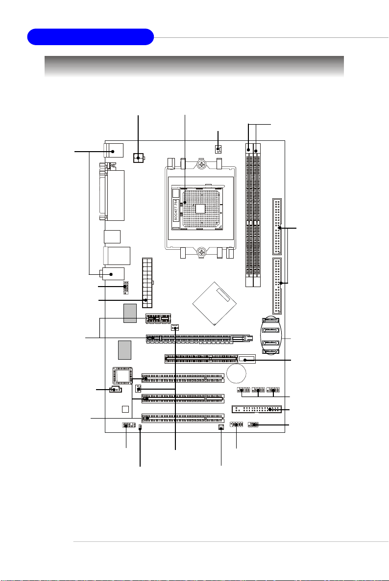
Quick Components Guide
Back Panel
I/O, p.E-13
JCOM1, p.E-16
JWR1, p.E-11
PCI Express
Slots, p.E-18
J1, p.E-14
PCI Slots, p.E-18
JPW1, p.E-11
Top: Mouse
Bottom: Keyboard
Top:
Parallel Port
Bottom:
COM Port
USB Ports
T: LAN Jack
B: USB Ports
Line-In
Line-Out
Mic
JCOM1
LAN
Winbond
W83627THF
S
O
I
B
Codec
JAUD1
JPW1
JWR1
SFAN1
JCI1
CPU, p.E-7
NBFAN1
AGR
CFAN1, p.E-15
T
T
A
B
JUSB1
JFP1
DDR DIMMs, p.E-10
2
E
IDE1/2, p.E-15
D
I
1
E
2
D
I
M
M
I
I
D
D
SATA1~4, p.E-14
AGR Slot, p.E-19
+
JUSB2
JUSB3
JUSB1/2/3, p.E-17
FDD1, p.E-14
JFP2
JFP2, p.E-16
E-6
JAUD1, p.E-16
JCI1, p.E-14
NBFAN1/
SFAN1, p.E-15
JFP1, p.E-16
SW_BAT1, p.E-17
Central Processing Unit: CPU
Gold arrow
Gold arrow
Gold arrow
Correct CPU placement
Incorrect CPU placement
Close
Press down
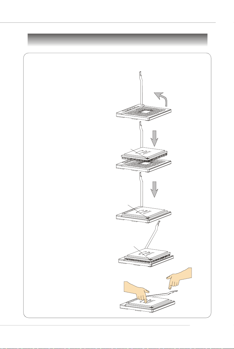
CPU Installation Procedures for Socket 754
1.Please turn off the power and
unplug the power cord before
installing the CPU.
Quick User’s Guide
Open Lever
2.Pull the lever sideways away
from the socket. Make sure to
raise the lever up to a 90degree angle.
3.Look for the gold arrow on the
CPU. The gold arrow should
point as shown in the picture.
The CPU can only fit in the
correct orientation.
4.If the CPU is correctly installed,
the pins should be completely
embedded into the socket and
cannot be seen. Please note
that any violation of the correct
installation procedures may
cause permanent damages to
your mainboard.
5. Press the CPU down firmly into
the socket and close the lever.
As the CPU is likely to move
while the lever is being closed,
always close the lever with
your fingers pressing tightly on
top of the CPU to make sure
the CPU is properly and
completely embedded into the
socket.
Sliding
Plate
90 degree
O
X
the CPU
Lever
E-7
MS-7135 ATX Mainboard
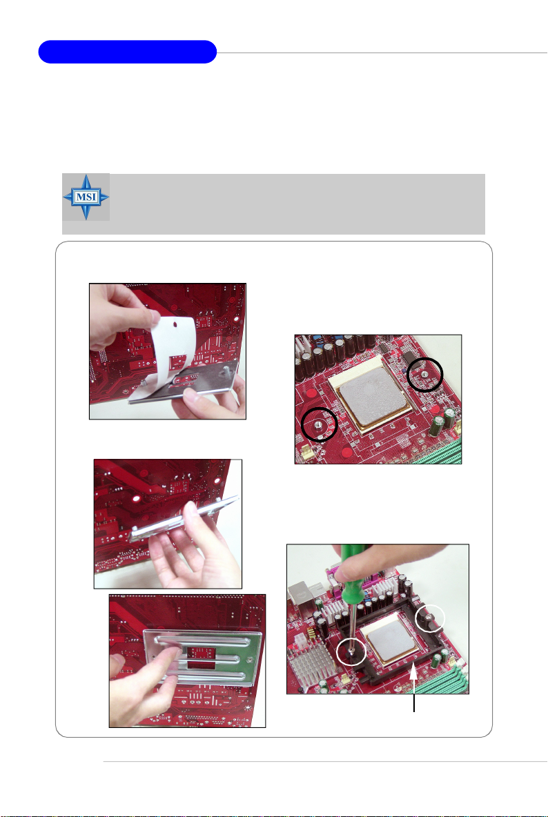
Installing AMD Athlon64 CPU Cooler Set
When you are installing the CPU, make sure the CPU has a heat sink
and a cooling fan attached on the top to prevent overheating. If you do not
have the heat sink and cooling fan, contact your dealer to purchase and install
them before turning on the computer.
MSI Reminds You...
Mainboard photos shown in this section are for demonstration of the
cooler installation for Socket 754 CPUs only. The appearance of
your mainboard may vary depending on the model you purchase.
1.Detach the shield off the
backplate’s paster.
2.Turn over the mainboard, and install
the backplate to the proper position.
3.Turn over the mainboard again, and
place the mainboard on the flat
surface. Locate the two screw
holes of the mainboard.
E-8
4.Align the retention mechanism and
the backplate.
Fix the retention mechanism and
the backplate with two screws.
retention mechanism
Quick User’s Guide
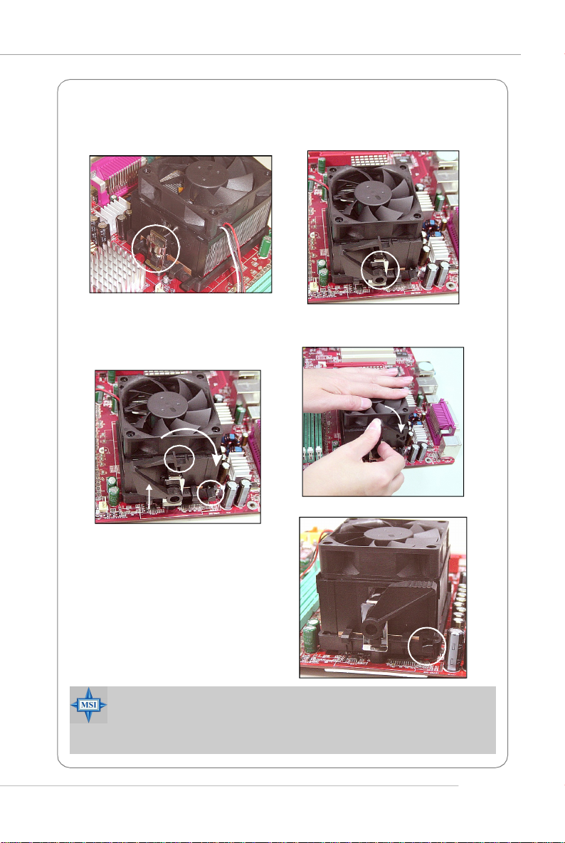
5.Position the cooling set onto the retention mechanism.
Hook one end of the clip to hook first, and then press down the other end of
the clip to fasten the cooling set on the top of the retention mechanism.
6.Locate the Fix Lever, Safety Hook
and the Fixed Bolt. Lift up the
intensive fixed lever.
Safety Hook
Fixed Lever
Fixed Bolt
8.Make sure the safety hook completely clasps the fixed bolt of the
retention mechanism.
9.Attach the CPU Fan cable to the
CPU fan connector on the
mainboard.
MSI Reminds You...
While disconnecting the Safety Hook from the fixed bolt, it is necessary to keep an eye on your fingers, because once the Safety Hook is
disconnected from the fixed bolt, the fixed lever will spring back instantly.
7.Fasten down the lever.
E-9
MS-7135 ATX Mainboard
Memory
The mainboard provides 2 slots for 184-pin DDR DIMM (Double In-Line Memory
Module) modules and supports the memory size up to 2GB. You can install DDR 333/
400 modules on the DDR DIMM slots (DIMM 1~2).
Memory Population Rules
Install at least one DIMM module on the slots. Each DIMM slot supports up to a
maximum size of 1GB. Users can install either single- or double-sided modules to
meet their own needs.
Slot Memory Module Total Memory
DIMM 1 Single/Double Side 64MB~1GB
DIMM 2 Single/Double Side 64MB~1GB
Maximum System Memory Supported 64MB~2GB
MSI Reminds You...
1. Make sure that you install memory modules of the same type and
density on DDR DIMMs.
2. For systems using double-sided DDR400 modules in single-channel mode, the maximum DRAM speed is DDR333.
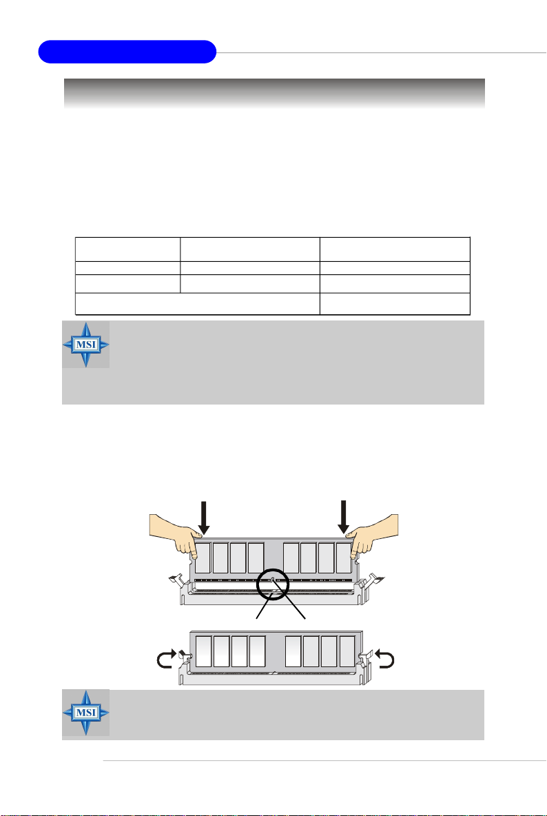
Installing DDR Modules
1. The DDR DIMM has only one notch on the center of module. The module will only
fit in the right orientation.
2. Insert the DIMM memory module vertically into the DIMM slot. Then push it in until
the golden finger on the memory module is deeply inserted in the socket.
3. The plastic clip at each side of the DIMM slot will automatically close.
E-10
Volt
MSI Reminds You...
You can barely see the golden finger if the module is properly
inserted into the socket.
Notch
Quick User’s Guide
Power Supply
The mainboard supports ATX power supply for the power system. Before
inserting the power supply connector, always make sure that all components are
installed properly to ensure that no damage will be caused.
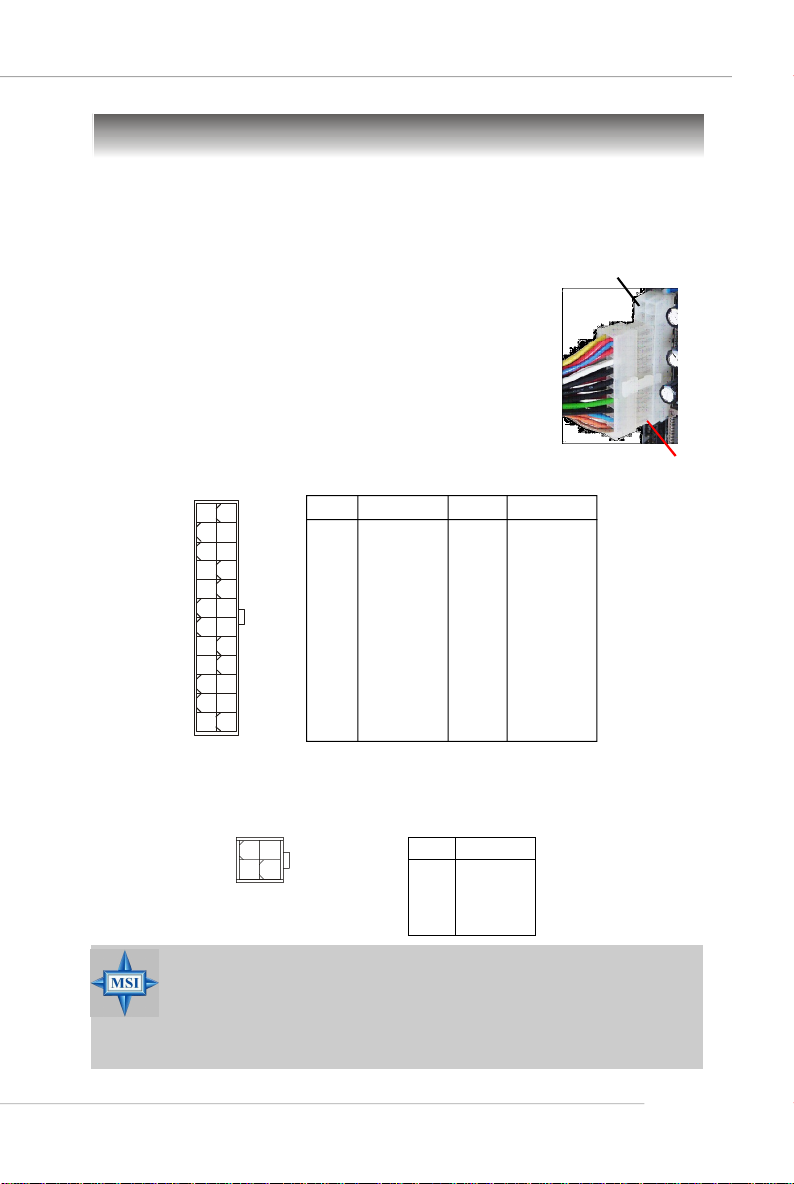
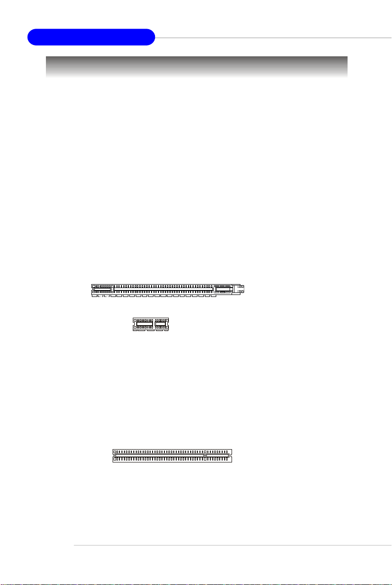
ATX 24-Pin Power Connector: JWR1
This connector allows you to connect an ATX 24-pin power
supply. To connect the ATX 24-pin power supply, make sure the
plug of the power supply is inserted in the proper orientation
and the pins are aligned. Then push down the power supply
firmly into the connector.
You may use the 20-pin ATX power supply as you like. If
you’d like to use the 20-pin ATX power supply, please plug your
power supply along with pin 1 & pin 13 (refer to the image at the
right hand). There is also a foolproof design on pin 11, 12, 23 &
24 to avoid wrong installation.
12 24
JWR1
1
13
PIN SIGNAL
1 +3.3V
2 +3.3V
3 GND
4 +5V
5 GND
6 +5V
7 GND
8 PWR OK
9 5VSB
10 +12V
11 +12V
12 NC
Pin Definition
PIN SIGNAL
13 +3.3V
14 -12V
15 GND
16 PS-ON#
17 GND
18 GND
19 GND
20 Res
21 +5V
22 +5V
23 +5V
24 GND
ATX 12V Power Connector: JPW1
This 12V power connector is used to provide power to the CPU.
JPW1 Pin Definition
1
2
JPW1
3
4
PIN SIGNAL
1 GND
2 GND
3 12V
4 12V
pin 12
pin 13
MSI Reminds You...
1. These two connectors connect to the ATX power supply and have to
work together to ensure stable operation of the mainboard.
2. Power supply of 350 watts (and above) is highly recommended for
system stability.
3. ATX 12V power connection should be greater than 18A.
E-11
MS-7135 ATX Mainboard
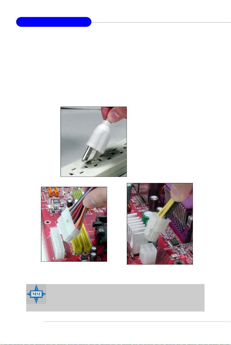
Important Notification about Power Issue
nVIDIA chipset is very sensitive to ESD (Electrostatic Discharge), therefore
this issue mostly happens while users intensively swap memory modules under S5
(power-off) states, and the power code is plugged while installing modules. Due to
several pins are very sensitive to ESD, so this kind of memory-replacement actions
might cause chipset system unable to boot. Please follow the following solution to
avoid this situation.
Unplug the AC power cable (shown in figure 1) or unplug the JWR1 & JPW1
power connectors (shown in figure 2 & figure 3) before the 1st installation or during
system upgrade procedure.
Figure 1:
Unplug the AC power cable
Unplug the JWR1 power connector
Figure 2:
MSI Reminds You...
Mainboard photos shown in this section are for demonstration only.
The appearance of your mainboard may vary depending on the model
you purchase.
E-12
Unplug the JPW1 power connector
Figure 3:
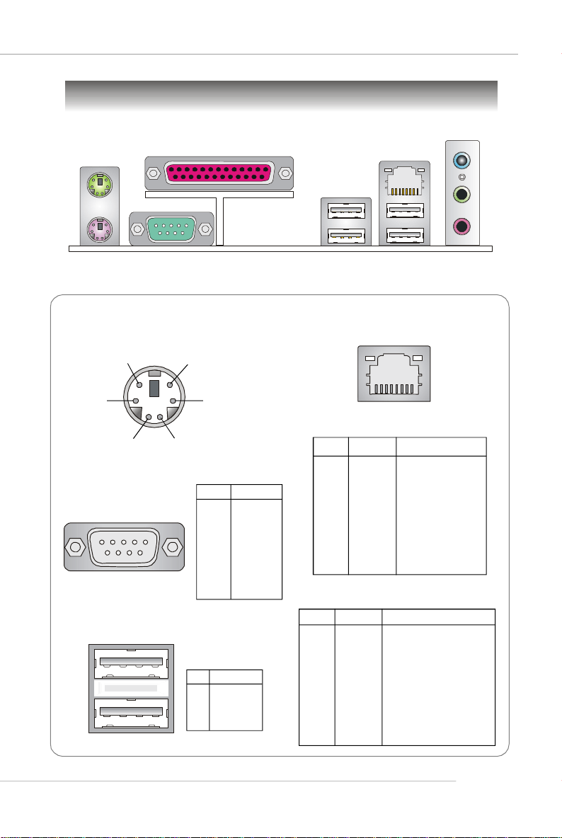
Mouse
Back Panel
Parallel
Quick User’s Guide
L-In
LAN
Keyboard
Serial Port
Mouse/Keyboard Connector
Pin5
Pin6 NC
Pin2 NC
Serial Port
1 2 3 4 5
6 7 8 9
Mouse/KBD Clock
Pin3 GNDPin4 VCC
Pin1
Mouse/KBD
DATA
PIN SIGNAL
1 DCD
2 SIN
3 SOUT
4 DTR
5 GND
6 DSR
7 RTS
8 CTS
9 RI
USB Ports
1 2 3 4
PIN SIGNAL
1 VCC
2 -Data
3 +Data
4 GND
USB Ports
RJ-45 LAN Jack
8 1
Gigabit LAN (Optional)
PIN SIGNAL DESCRIPTION
1 D0P Differential Pair 0+
2 D0N Differential Pair 03 D1P Differential Pair 1+
4 D2P Differential Pair 2+
5 D2N Differential Pair 26 D1N Differential Pair 17 D3P Differential Pair 3+
8 D3N Differential Pair 3-
10/100 LAN (Optional)
PIN SIGNAL DESCRIPTION
1 TDP Transmit Differential Pair
2 TDN Transmit Differential Pair
3 RDP Receive Differential Pair
4 NC Not Used
5 NC Not Used
6 RDN Receive Differential Pair
7 NC Not Used
8 NC Not Used
L-Out
Mic
E-13
MS-7135 ATX Mainboard
Connectors
Floppy Disk Drive Connector: FDD1
The mainboard provides a standard floppy disk drive connector that supports
360K, 720K, 1.2M, 1.44M and 2.88M floppy disk types.
FDD1
CD-In Connector: J1
This connector is provided for CD-ROM audio.
Chassis Intrusion Switch Connector: JCI1
This connector is connected to a 2-pin chassis switch. If
the chassis is opened, the switch will be short. The system will
record this status and show a warning message on the screen.
To clear the warning, you must enter the BIOS utility and clear the
record.
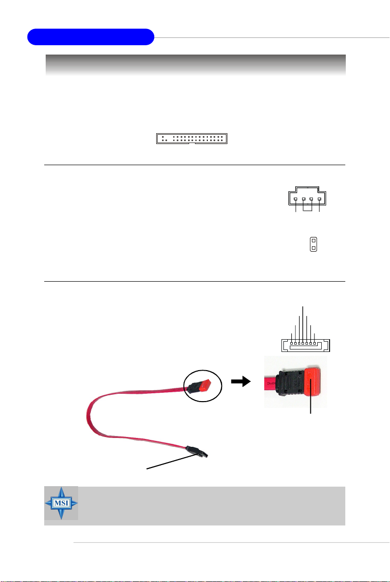
Serial ATA Connectors: SATA1~SATA4
SATA1~SATA4 are high-speed Serial ATA interface ports.
Each supports 1st generation serial ATA data rates of 150MB/s
and is fully compliant with Serial ATA 1.0 specifications. Each
Serial ATA connector can connect to 1 hard disk device.
Serial ATA cable
Take out the dust cover and
connect to the hard disk
devices
CINTRU
RXN
RXP
GND
R
GND
GND
J1
GND
JCI1
TXN
TXP
L
2
1
GND
E-14
Connect to SATA1/2/3/4
MSI Reminds You...
Please do not fold the Serial ATA cable into 90-degree angle. Otherwise,
data loss may occur during transmission.
Quick User’s Guide
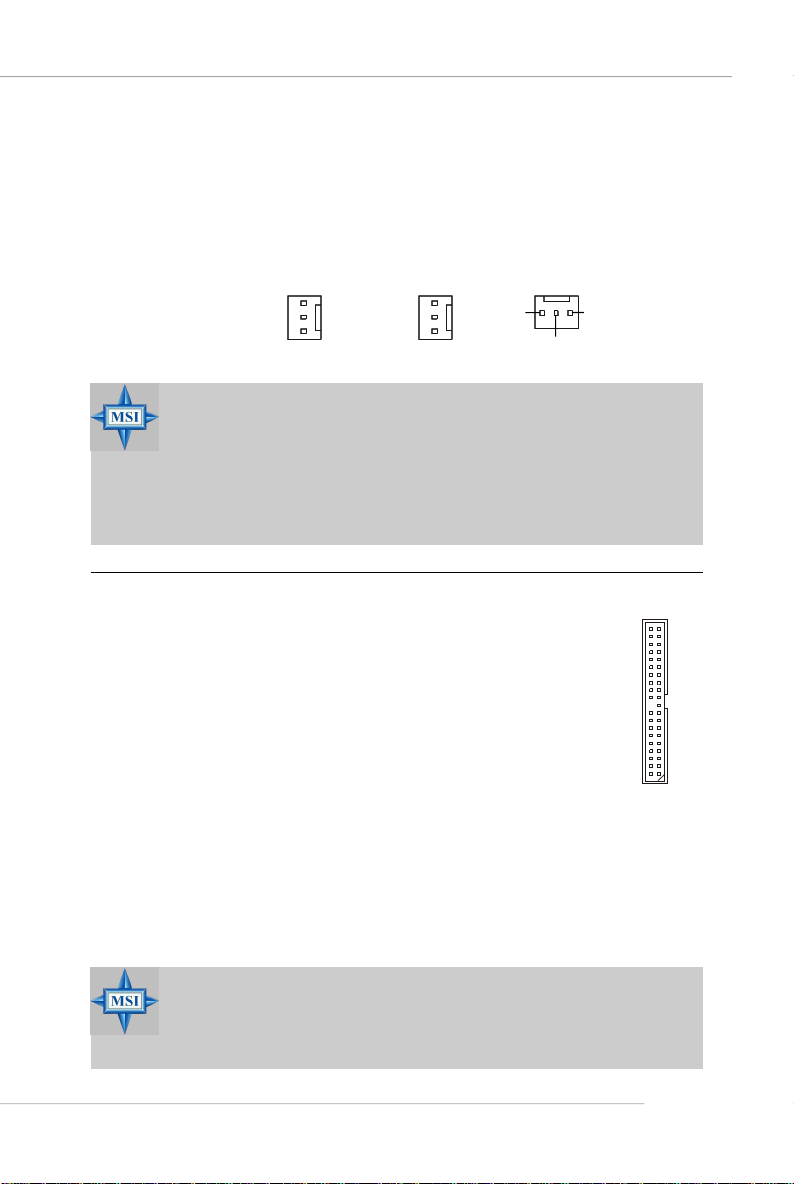
Fan Power Connectors: CFAN1 / SFAN1 / NBFAN1
The fan power connectors support system cooling fan with +12V. When
connecting the wire to the connectors, always note that the red wire is the positive
and should be connected to the +12V, the black wire is Ground and should be
connected to GND. If the mainboard has a System Hardware Monitor chipset onboard,
you must use a specially designed fan with speed sensor to take advantage of the
CPU fan control.
Sensor
+12V
GND
CFAN1
Sensor
+12V
GND
SFAN1
Sensor
GND
+12V
NBFAN1
MSI Reminds You...
1. Always consult the vendors for proper CPU cooling fan.
2. CFAN1 supports Smart Fan control. You can install Core Center
utility that will automatically control the CPU fan speed according
to the actual CPU temperature. Alternatively, you may set up the
smart fan control functions in the BIOS setup utility.
3. Please refer to the recommended CPU fans at AMD® official website.
ATA133 Hard Disk Connectors: IDE1 & IDE2
The mainboard has a 32-bit Enhanced PCI IDE and Ultra DMA 66/100/
133 controller that provides PIO mode 0~4, Bus Master, and Ultra DMA 66/
100/133 function. You can connect up to four hard disk drives, CD-ROM
and other IDE devices.
The Ultra ATA133 interface boosts data transfer rates between the
computer and the hard drive up to 133 megabytes (MB) per second. The
new interface is one-third faster than earlier record-breaking Ultra ATA/
100 technology and is backwards compatible with the existing Ultra ATA
interface.
IDE1 (Primary IDE Connector)
The first hard drive should always be connected to IDE1. IDE1 can connect a Master
and a Slave drive. You must configure second hard drive to Slave mode by setting the
jumper accordingly.
IDE2 (Secondary IDE Connector)
IDE2 can also connect a Master and a Slave drive.
MSI Reminds You...
If you install two hard disks on cable, you must configure the second
drive to Slave mode by setting its jumper. Refer to the hard disk documentation supplied by hard disk vendors for jumper setting instructions.
E-15
MS-7135 ATX Mainboard
Serial Port Header: JCOM1
The mainboard offers one 9-pin header as serial port.
The port is a 16550A high speed communication port that
sends/receives 16 bytes FIFOs. You can attach a serial
mouse or other serial device directly to it.
Data Carry
Detect
Serial Out
GND
Request
To Send
Ring
Indicate
JCOM1
Serial In
Data
Terminal
Ready
Data Set
Ready
Clear
To Send
Front Panel Connectors: JFP1, JFP2
The mainboard provides two front panel connectors for electrical connection
to the front panel switches and LEDs. The JFP1 is compliant with Intel® Front Panel I/
O Connectivity Design Guide.
RST_SW_N
RST_SW_P
Reserved
JFP1
PWR_SW_N
HDD_LED_N
HDD_LED_P
FP PWR/SLP
FP PWR/SLP
PWR_SW_P
JFP2
SPK+
PLED
BUZ-
SLED
BUZ+
GND
SPK-
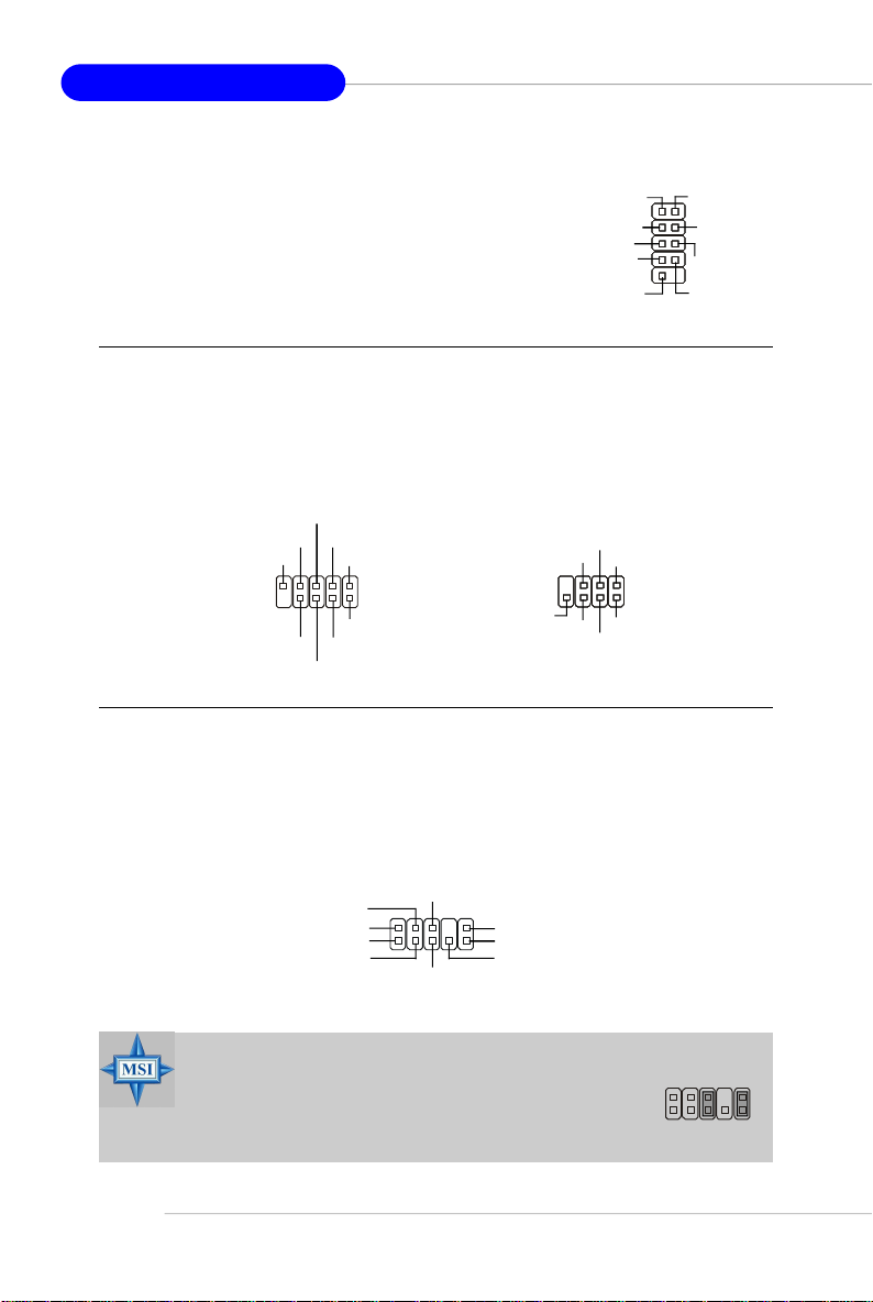
Front Panel Audio Connector: JAUD1
The JAUD1 front panel audio connector allows you to connect to the front
panel audio and is compliant with Intel® Front Panel I/O Connectivity Design Guide.
E-16
JAUD1
AUD_VCC
AUD_GND
AUD_MIC
AUD_MIC_BIAS
AUD_RET_R
2
1
AUD_FPOUT_R
10
AUD_RET_L
AUD_FPOUT_L
9
HP_ON
MSI Reminds You...
If you don’t want to connect to the front audio header, pins
5 & 6, 9 & 10 have to be jumpered in order to have signal
output directed to the rear audio ports. Otherwise, the
Line-Out connector on the back panel will not function.
6
10
5
9
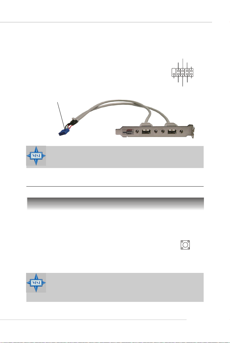
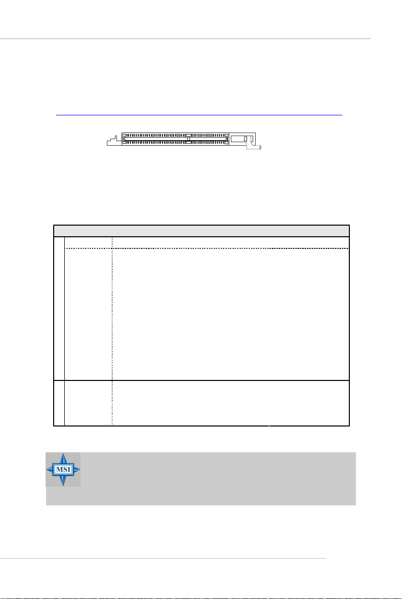
Front USB Connectors: JUSB1, JUSB2, JUSB3
The mainboard provides three standard USB 2.0
pin headers. USB 2.0 technology increases data
transfer rate up to a maximum throughput of 480Mbps,
which is 40 times faster than USB 1.1, and is ideal for
connecting high-speed USB interface peripherals such
as USB HDD, digital cameras, MP3 players,
printers, modems and the like.
Connect to JUSB1, JUSB2, or
JUSB3
MSI Reminds You...
Note that the pins of VCC and GND must be connected correctly to
avoid possible damage.
Quick User’s Guide
USB0+
USB0-
GND
VCC
JUSB1/2/3
USBOC
USB 2.0 Bracket
(Optional)
GND
USB1-
USB1+
VCC
Jumpers/Buttons
Clear CMOS Button: SW_BAT1
CMOS stands for Complementary Metal-Oxide Semiconductor and is more specifically referred to as CMOS RAM. It is a tiny 64-byte region of memory
that, owing to battery power, retains system configuration data when
the PC is shut off. With the CMOS RAM, the system can automatically
boot OS every time it is turned on. If you want to clear the system
configuration, press the SW_BAT1 button to have the data erased.
MSI Reminds You...
You can clear CMOS by pressing this button while the system is off.
Avoid clearing CMOS while the system is on; it will damage the
mainboard.
SW_BAT1
E-17
MS-7135 ATX Mainboard
Slots
The motherboard provides one PCI Express x1 slot, one PCI Express x16 slot,
three 32-bit PCI slots, and one AGR slot.
PCI (Peripheral Component Interconnect) Express Slots
The PCI Express slots support high-bandwidth, low pin count, and serial
interconnect technology. You can insert the expansion cards to meet your needs.
When adding or removing expansion cards, make sure that you unplug the power
supply first.
PCI Express architecture provides a high performance I/O infrastructure for
Desktop Platforms with transfer rates starting at 2.5 Giga transfers per second over
a PCI Express x1 lane for Gigabit Ethernet, TV Tuners, 1394 controllers, and general
purpose I/O. Also, desktop platforms with PCI Express Architecture will be designed
to deliver highest performance in video, graphics, multimedia and other sophisticated
applications. Moreover, PCI Express architecture provides a high performance graphics
infrastructure for Desktop Platforms doubling the capability of existing AGP 8x designs with transfer rates of 4.0 GB/s over a PCI Express x16 lane for graphics
controllers, while PCI Express x1 supports transfer rate of 250 MB/s.
PCI Express x16 slot
PCI Express x1 slot
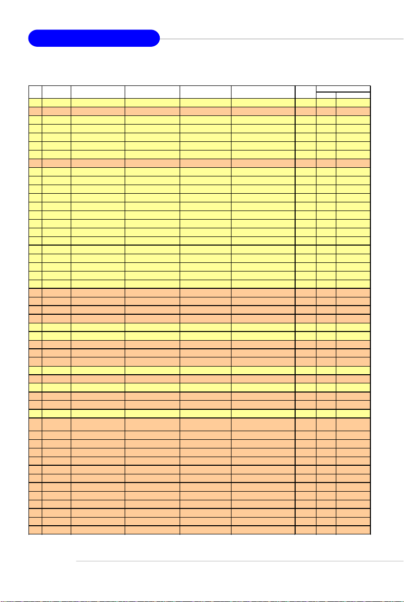
PCI (Peripheral Component Interconnect) Slots
The PCI slots allow you to insert the expansion cards to meet your needs.
When adding or removing expansion cards, make sure that you unplug the power
supply first. Meanwhile, read the documentation for the expansion card to make any
necessary hardware or software settings for the expansion card, such as jumpers,
switches or BIOS configuration.
PCI Slots
E-18
Quick User’s Guide
AGR (Advance Graphics Riser) Slot
The AGR slot is a special design that only supports compatible AGP VGA
cards. For more detailed information on compatible AGP VGA cards, please refer
to http://www.msi.com.tw/program/products/mainboard/mbd_index.php .
AGR Slot
Compatible VGA Card List
System Configuration
Manufacturer Model No. Spec.
Processor AMD Athlon™ 64 Processor 2800+ FSB 200
Memory Transcend SEC K4H280838D-TCB3 DDR333 / 256MB
VGA Card As Follows
Lan Card Onboard
Sound Card Onboard
Hard Drive Hitachi HDS7222580VLSA80 SATA150 / 82.3GB
CD-ROM BenQ CD652A 52X
Floppy Drive TEAC FD-235HF 1.44MB
Power Supply DELTA DPS-300KB-1A 300W
Mouse Acer M-S69 PS/2
Keyboard Acer 6511-CX PS/2
Monitor ViewSonic P225f 22”CRT
Device Configuration
VGA BIOS
VGA Driver
MB Driver (from NVOM011 CD)
SW Info
MSI Reminds You...
The VGA BIOS and driver versions need to be identical to the versions in the compatibility list in order to have the AGR function work
properly.
E-19
MS-7135 ATX Mainboard
MS-7135
VGA CARD
Vender
1 Alvatron FX5700U GeForce FX5700 Ultra 128MB/DDR SDRAM 4.36.20.18.01 8X Pass 6.14.10.6681
2 ATI Fire GL 8800 Fire GL 8800 128MB/SDRAM 1.03 4X Pass 6.14.10.6462
3 GAINWARD GFX 5900 Ultra GeForce 4 FX 5900 U 256MB/DDR SDRAM 4.35.20.24.00 8X Pass 6.14.10.6681
4 Gigabyte GV-R9200 Radeon 9200 128MB/DDR SDRAM BK-AMI 8.9 8X Pass 6.14.10.6430
5 Gigabyte GV-N57L128D GeForce FX5700LE 128MB/DDR SDRAM 4.36.20.30.00 8X Pass 6.14.10.6172
6 Leadtek Winfast A360LE TD GeForce FX5700LE 128MB/DDR SDRAM 4.36.20.30.00 8X Pass 6.14.10.6681
7 Leadtek Winfast A400GT TDH GeForce 6800GT 256MB/DDR SDRAM 5.40.02.15.00 8X Pass 6.14.10.6681
8 MSI MS-8863 GeForce 4 MX 460 64MB/SDRAM 4.17.00.30.06 4X Pass 6.14.10.6681
9 MSI MS-8907 GeForce FX 5200 64MB/DDR SDRAM 4.34.20.22.00 8X Pass 6.14.10.6681
10 MSI MS-8911 GeForce FX 5200 128MB/DDR SDRAM 4.34.20.15.00 8X Pass 6.14.10.6681
11 MSI MS-8919 GeForce FX 5200 128MB/DDR SDRAM 4.34.20.23.08 8X Pass 6.14.10.6681
12 MSI MS-8923 GeForce FX 5200 Ultra 128MB/DDR SDRAM 4.34.20.23.00 8X Pass 6.14.10.6681
13 MSI MS-8929 GeForce FX 5900 128MB/DDR SDRAM 4.35.20.18.04 8X Pass 6.14.10.6681
14 MSI MS-8931 GeForce FX 5600 Ultra 128MB/DDR SDRAM 4.31.20.51.00 8X Pass 6.14.10.6681
15 MSI MS-8936 GeForce4 MX4000 64MB/DDR SDRAM 4.18.20.42.00 8X Pass 6.14.10.6172
16 MSI MS-8936 GeForce FX5500 128MB/DDR SDRAM 4.34.20.66.03 8X Pass 6.14.10.6172
17 MSI MS-8946 GeForce FX 5950 Ultra 256MB/DDR SDRAM 4.35.20.32.16 8X Pass 6.14.10.6172
18 MSI MS-8959 GeForce FX5700LE 128MB/DDR SDRAM 4.36.20.30.10 8X Pass 6.14.10.6681
19 MSI MS-8975 Nvidia GeForce 6800 128MB/DDR SDRAM 5.40.02.12.01 8X Pass 6.14.10.6172
20 Unika FX5200 SP5208 GeForce FX5200 64MB/DDR SDRAM 4.34.20.42.00 8X Pass 6.14.10.6172
21 MSI MS-8952 ATI Radeon 9250 128MB/DDR SDRAM 008.017D.031.000 8X Pass 6.14.10.6476
22 Power ColorR92U-LC3 Radeon 9250 128MB/DDR SDRAM 008.017D.016.000 8X Pass 6.14.10.6476
23 Power ColorRV6DE-NB3 Radeon 7000 64MB/DDR SDRAM 008.004.008.000 4X Pass 6.14.10.6453
24 ATI Radeon LE Radeon LE DDR 32MB/DDR SGRAM P/N113-10604-100 4X Pass 6.13.10.6153
25 ATI Fire GL 8700 Fire GL 8700 64MB/DDR SDRAM 1.11 4X Pass 6.12.10.3051
26 ATI Radeon 9000 Pro Radeon DDR 64MB/DDR SDRAM BK8.0.0 4X Pass 6.14.10.6458
27 ATI Radeon 9500 Radeon 9500 64MB/DDR SDRAM 113.94210.100 8X Pass 6.14.10.6458
28 ATI Radeon 9700 Radeon 9700 128MB/DDR SDRAM 113.94206.101 8X Pass 6.14.10.6458
29 ASUS AGP-V7700 Deluxe GeForce 2 GTS 32MB/DDR SGRAM 2.15.01.13 4X Pass 2.9.5.8
30 ASUS V8440 GeForce 4 Ti 4400 128MB/SDRAM 4.25.0022 4X Pass 2.9.5.8
31 ASUS V8460 Ultra GeForce 4 Ti 4600 128MB/SDRAM 4.25.0019 4X Pass 6.6.8.1
32 Creative 3D Blaster 5 RX9700 ProRadeon 9700 128MB/SGRAM 113.94206.101 8X Pass 6.14.10.6458
33 ELSA Gladiac 517 SV GeForce 4 MX420 64MB/SDRAM 4.17.00.24.E1 4X Pass 2.9.5.8
34 ELSA Gladiac 528 Ultra GeForce 4 Ti 4200 128MB/DDR SDRAM 4.28.20.21.E0 8X Pass 6.6.8.1
35 GAINWARD GeForce 4 MX460 64MB/DDR 4.17.0030 4X Pass 2.9.5.8
36 GAINWARD GeForce 4 MX440T 64MB/SDRAM 4.17.00.30 4X Pass 2.9.5.8
37 GAINWARD GeForce 4 MX440 64MB/DDR SDRAM 4.18.2007 8X Pass 6.6.8.1
38 Leadtek Winfast
39 Leadtek Winfast A170 TH GeForce 4 MX 420 64MB/SDRAM 4.17.00.28 4X Pass 2.9.5.8
40 Leadtek Winfast A250 TD GeForce 4 4400 Ti 128MB/SDRAM 4.25.0022 4X Pass 6.6.8.1
41 MSI MS-8806 Nvidia RIVA TNT2 32MB/SDRAM 2.05.17.03.00 4X Pass 6.6.8.1
42 MSI MS-8831 GeForce GTS Pro 64MB/SDRAM 3.15.01.00.07 4X Pass 6.6.8.1
43 MSI MS-8847 GeForce 4 MX 440 64MB/DDR SDRAM 4.17.0045 4X Pass 6.6.8.1
44 MSI MS-8851 GeForce 3 Ti 200 64MB/SDRAM 3.20.00.18.11 4X Pass 2.9.5.8
45 MSI MS-8852 GeForce 2 MX 100/200 32MB/SDRAM 3.11.0148 4X Pass 2.9.5.8
46 MSI MS-8860 GeForce 4 MX 440 64MB/SDRAM 4.17.00.24.52 4X Pass 2.9.5.8
47 MSI MS-8861 GeForce 4 MX 440 64MB/SDRAM 4.17.00.24.46 4X Pass 2.9.5.8
48 MSI MS-8870 GForce 4 Ti 4200 64MB/DDR SDRAM 4.25.00.29.10 4X Pass 2.9.5.8
49 MSI MS-8872 GeForce 4 Ti 4600 128MB/DDR SDRAM 4.25.00.27.33 4X Pass 2.9.5.8
50 MSI MS-8879 GeForce 4 Ti 4200 64MB/DDR SDRAM 4.25.0032 4X Pass 2.9.5.8
Model name VGA Chip
GeForce3 Titanium 500
TD
VGA Memory
64MB/SDRAM V11.05.2001 4X Pass 6.6.8.1
VGA BIOSNo.
AGP
SPEED
Result Driver Ver.
E-20
 Loading...