


K8MM-V
i
FCC-B Radio Frequency Interference Statement
This equipment has been tested and found to comply with the limits for a class B digital device, pursuant to part
15 of the FCC rules. These limits are designed to provide reasonable protection against harmful interference
when the equipment is operated in a commercial environment. This equipment generates, uses and can
radiate radio frequency energy and, if not installed and used in accordance with the instruction manual, may
cause harmful interference to radio communications. Operation of this equipment in a residential area is likely
to cause harmful interference, in which case the user will be required to correct the interference at his own
expense.
Notice 1
The changes or modifications not expressly approved by the party responsible for compliance could void the
user’s authority to operate the equipment.
Notice 2
Shielded interface cables and A.C. power cord, if any, must be used in order to comply with the emission limits.
VOIR LA NOTICE D’NSTALLATION AVANT DE RACCORDER AU RESEAU.
Micro-Star International
MS-7142
This device complies with Part 15 of the FCC Rules. Operation is subject to the following two conditions:
(1) this device may not cause harmful interference, and
(2) this device must accept any interference received, including interference that may cause undesired
operation
G52-M7142X1

ii
Copyright Notice
The material in this document is the intellectual property of MICRO-STAR INTERNATIONAL. We take every
care in the preparation of this document, but no guarantee is given as to the correctness of its contents. Our
products are under continual improvement and we reserve the right to make changes without notice.
Trademarks
All trademarks are the properties of their respective owners.
AMD, Athlon™ Athlon™XP, Thoroughbred™ and Duron™ are registered trademarks of AMD Corporation.
Intel® and Pentium® are registered trademarks of Intel Corporation.
PS/2 and OS® 2 are registered tradem arks of International Business Machines Corporation.
Microsoft® is a registered trademark of Microsoft Corporation. Windows® 98/2000/NT/XP are registered
trademarks of Microsoft Corporation.
NVIDIA, the NVIDIA logo, DualNet, and nForce are registered trademarks or trademarks of NVIDIA
Corporation in the United States and/or other countries.
Netware® is a registered trademark of Novell, Inc.
Award® is a registered trademark of Phoenix Technologies Ltd.
AMI® is a registered trademark of American Megatrends Inc.
Kensington and MicroSaver are registered trademarks of the Kensington Technology Group.
PCMCIA and CardBus are registered trademarks of the Personal Computer Memory Card International
Association.
Revision History
Revision Revision History Date
V1.0 First released of Multi-language version for PCB 1.x February 2005
with chipsets VIA ® K8M800-CE & VIA ® VT8237R

iii
Safety Instructions
1. Always read the safety instructions carefully.
2. Keep this User Manual for future reference.
3. Keep this equipment away from humidity.
4. Lay this equipment on a reliable flat surface before setting it up.
5. The openings on the enclosure are for air convection hence protects the equipment from overheating. Do
not cover the openings.
6. Make sure the voltage of the power source and adjust properly 110/220V before connecting the equipment
to the power inlet.
7. Place the power cord such a way that people can not step on it. Do not place anything over the power
cord.
8. Always Unplug the Power Cord before inserting any add-on card or module.
9. All cautions and warnings on the equipment should be noted.
10. Never pour any liquid into the opening that could damage or cause electrical shock.
11. If any of the following situations arises, get the equipment checked by a service personnel:
- The power cord or plug is damaged.
- Liquid has penetrated into the equipm ent.
- The equipment has been exposed to moisture.
- The equipment does not work well or you can not get it work according to User Manual.
- The equipment has dropped and damaged.
- The equipment has obvious sign of breakage.
12. Do not leave this equipment in an environment unconditioned, storage temperature above 60° C (140°F),
it may damage the equipment.
CAUTION: Danger of explosion if battery is incorrectly replaced. Replace only
with the same or equivalent type recommended by the manufacturer.

iv
Table of Content
English.....................................................................1
Deutsch....................................................................17
Français...................................................................33
简体中文 ...................................................................49
繁體中文 ...................................................................63
日本語.......................................................................77
1
Introduction
Thank you for choosing the K8MM-V Series (MS-7142 v1.X) micro ATX mainboard. The K8MM-V
Series is based on VIA ® K8M800-CE & VT8237R chipsets for optimal system efficiency. Designed to
fit the advanced AMD ® K8 Athlon64 processors in 754 pin package, the K8MM-V Series delivers a
high performance and professional desktop platform solution.
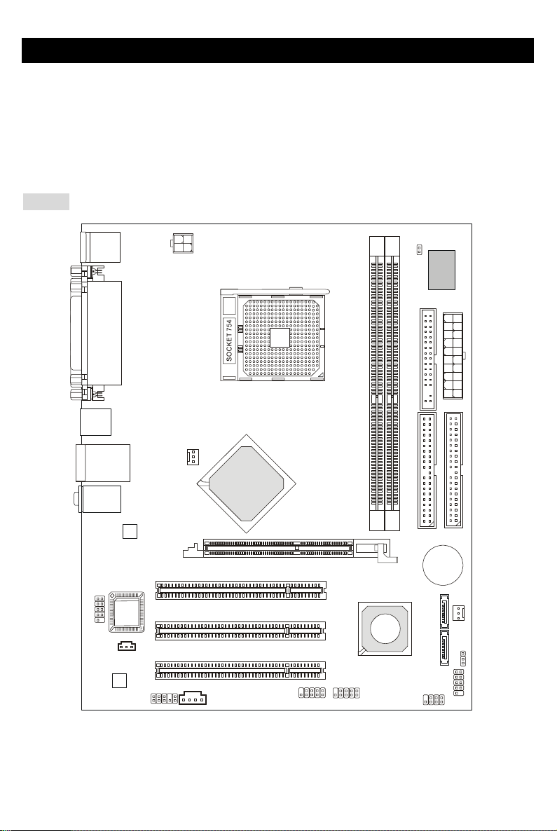
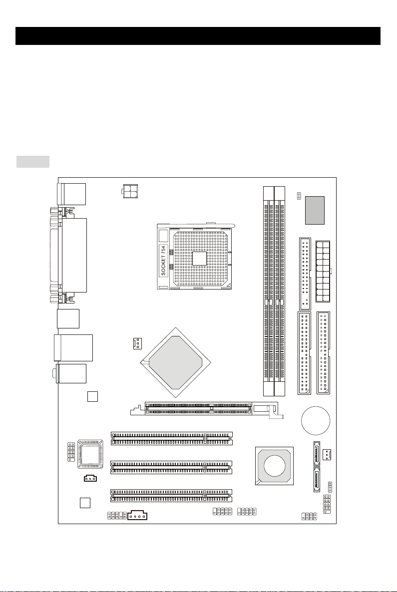
Layout
SFAN1
CPUFAN1
JPW1
F
D
D
1
SATA1
SATA2
T:
M:
B:
Line-In
Line-Out
Mic
T: L AN ja ck
B: USB ports
Winbond
W83627THF
VIA
K8M800-CE
BATT
+
D
D
R
1
D
D
R
2
JWR2
JCASE1
I
D
E
1
I
D
E
2
JFP1
JFP2
JBAT1
JAUD1
J1
Top : Pa rall el Por t
Bottom:
COM A
VGA Port
Top : mo use
Bottom: keyboard
USB ports
BIOS
AGP Slot
PCI S lot 3
PCI S lot 2
PCI S lot 1
JUSB1
JUSB2
JCOM1
(Optional)
Codec
VIA
VT6103L
JSP1
VIA
VT8237R

2
Specifications
CPU
z Supports 64-bit AMD®K8 Athlon64 processor (Socket 754)
z Supports 3700+ and higher CPU
(For the latest information about CPU, please visit
http://www.msi.com.tw/program/products/mainboard/mbd/pro_mbd_cpu_support.php )
Chipset
z VIA®K8M800-CE Chipset
-HyperTransport
TM
connection to AMD K8 Athlon64 processor
- 8 or 16 bit control/address/data transfer both directions
- 800/600/400/200 MHz “Double Data Rate” operation both direction
- AGP v3.0 compliant with 8x transfer mode
- Graphic integrated
z VIA®VT8237R chipset (487 BGA)
- Supports dual channel native SATA controller up to 150MB/s
- Integrated Hardware Sound Blaster/Direct Sound AC97 audio
- Ultra DMA 66/100/133 master mode PCI EIDE controller
- ACPI & PC2001 compliant enhanced power management
- Supports USB2.0 up to 8 ports
- Supports RAID0 or RAID1
Main Memory
z Supports DDR266/333/400 DDR SDRAM for two 184-pin DDR DIMMs.
z Supports a maximum memory size of 2GB
(For the updated supporting memory modules, please visit
http://www.msi.com.tw/program/products/mainboard/mbd/pro_mbd_trp_list.php )
Slots
z One (Accelerated Graphics Port) AGP slot.
-AGP 3.0 specification compliant
z Three 32-bit Master 3.3v/5v PCI Bus slots

3
On-Board IDE
z An IDE controller on the VIA®VT8237R chipset provides IDE HDD/CD-ROM with PIO, Bus Master
and Ultra DMA 66/100/133 operation modes
z Can connect up to 4 IDE devices
z Serial ATA/150 controller integrated by VT8237R
- Up to 150MB/s transfer rate
- Can connect up to two serial ATA devices
On-Board Peripherals
z On-Board Peripherals include:
- 1 floppy port supports 1 FDD with 360K, 720K, 1.2M,
- 1 serial port (COMA)
- 1 VGA port
- 1 parallel port supporting SPP/EPP/ECP mode
- 8 USB2.0 ports (Rear*4/Front*4)
- 1 Audio (Line-In/Line-Out/MIC) port
- 1 RJ-45 LAN Jack
- 2 IDE ports support 4 IDE devices
- 2 serial ATA ports
- 1 JCOM1 pin header(Optional)
Audio
z 6 channels software audio codec VIA VT1617A.
- Compliance with AC97 v2.3 Spec.
- Meet PC2001 audio performance requirement.
LAN
z VIA®VT6103L 10/100 Mb/s phy.
- Compliant with PCI v2.2.
- Supports ACPI Power Management.

4
BIOS
z The mainboard BIOS provides “Plug & Play” BIOS which detects the peripheral devices and
expansion cards of the board automatically.
z The mainboard provides a Desktop Management Interface (DMI) function that records your
mainboard specifications.
Dimension
z Micro-ATX Form Factor: 243mm x 195mm.
Mounting
z 6 mounting holes.
5
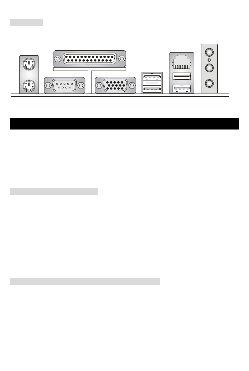
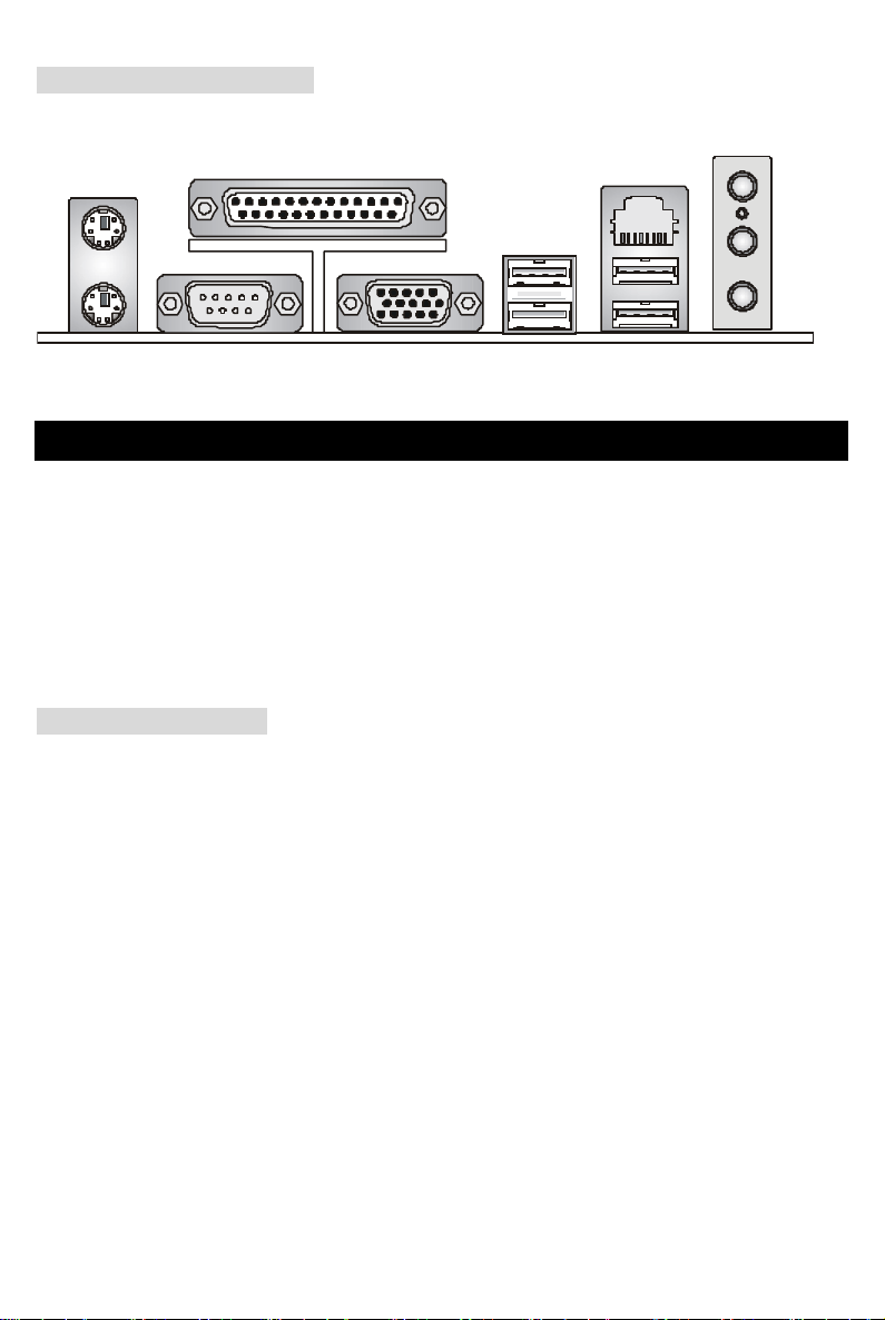
Rear Panel
The back panel provides the following connectors:
Ke
y
board
USB Ports
Mouse
COM
p
ort
V
GA
p
ort
Parallel Port
Line In
Line Ou
t
Mic In
LAN
USB Ports
Hardware Setup
This chapter tells you how to install the CPU, memory modules, and expansion cards, as well as how to
setup the jumpers on the mainboard. It also provides the instructions on connecting the peripheral
devices, such as the mouse, keyboard, etc. While doing the installation, be careful in holding the
components and follow the installation procedures.
Central Processing Unit: CPU
The mainboard supports AMD ® Athlon64 processor. The mainboard uses a CPU socket called
Socket-754 for easy CPU installation. When you are installing the CPU, make sure the CPU has a heat
sink and a cooling fan attached on the top to prevent overheating. If you do not have the heat sink and
cooling fan, contact your dealer to purchase and install them before turning on the computer.
(For the latest information about CPU, please visit
http://www.msi.com.tw/program/products/mainboard/mbd/pro_mbd_cpu_support.php )
Example of CPU Core Speed Derivation Procedure
If CPU Clock = 200MHz
Core/Bus ratio = 12
then CPU core speed = Host Clock x Core/Bus ratio
= 200MHz x 12
= 2.4 GHz

6
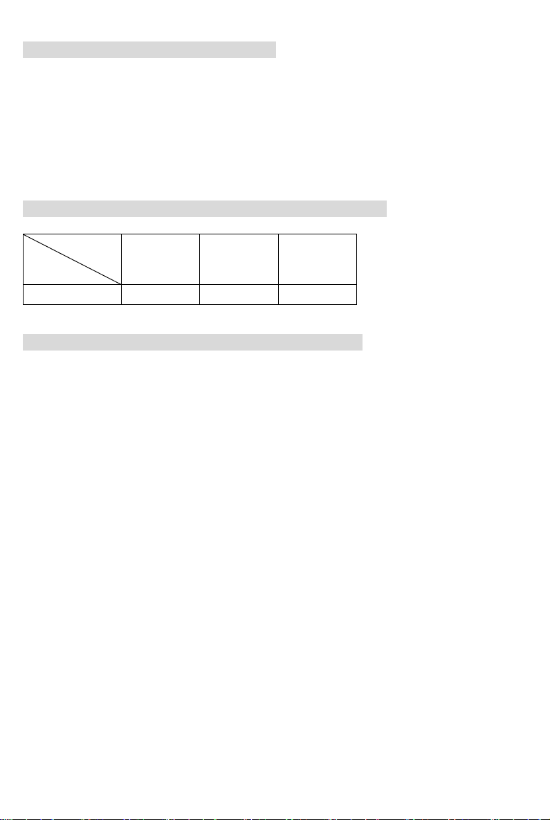
Memory Speed/CPU FSB Support Matrix
Memory
FSB
DDR 266 DDR 333 DDR 400
800 MHz OK OK OK
CPU Installation Procedures for Socket 754
1. Please turn off the power and unplug the power cord before installing the CPU.
2. Pull the lever sideways away from the socket. Make sure to raise the lever up to a 90-degree
angle.
3. Look for the gold arrow on the CPU. The CPU can only fit in the correct orientation. Lower the
CPU down onto the socket.
4. If the CPU is correctly installed, the pins should be completely embedded into the socket and
can not be seen. Please note that any violation of the correct installation procedures may
cause permanent damages to your mainboard.
5. Press the CPU down firmly into the socket and close the lever. As the CPU is likely to move
while the lever is being closed, always close the lever with your fingers pressing tightly on top of
the CPU to make sure the CPU is properly and completely embedded into the socket.
Installing AMD Athlon64 CPU Cooler Set
When you are installing the CPU, make sure the CPU has a heat sink and a cooling fan attached on the
top to prevent overheating. If you do not have the heat sink and cooling fan, contact your dealer to
purchase and install them before turning on the computer.
1. Detach the shield of the backplate’s paster.
2. Turn over the mainboard, and install the backplate to the proper position.
3. Turn over the mainboard again and place the mainboard on the flat surface. Locate the two
screw holes of the mainboard.
4. Align the retention mechanism and the backplate. Fix the retention mechanism and the
backplate with two screws.

7
5. Position the cooling set onto the retention mechanism. Hook one end of the clip to hook first.
6. Press down the other end of the clip to fasten the cooling set on the top of the retention
mechanism.
7. Locate the Fix Lever, Safety Hook and the Fixed Bolt. Lift up the intensive fixed lever.
8. Fasten down the lever.
9. Make sure the safety hook completely clasps the fixed bolt of the retention mechanism.
MSI Reminds You...
While disconnecting the Safety Hook from the fixed bolt, it is necessary to keep an eye on your fingers,
because once the Safety Hook is disconnected from the fixed bolt, the fixed lever will spring back
instantly.
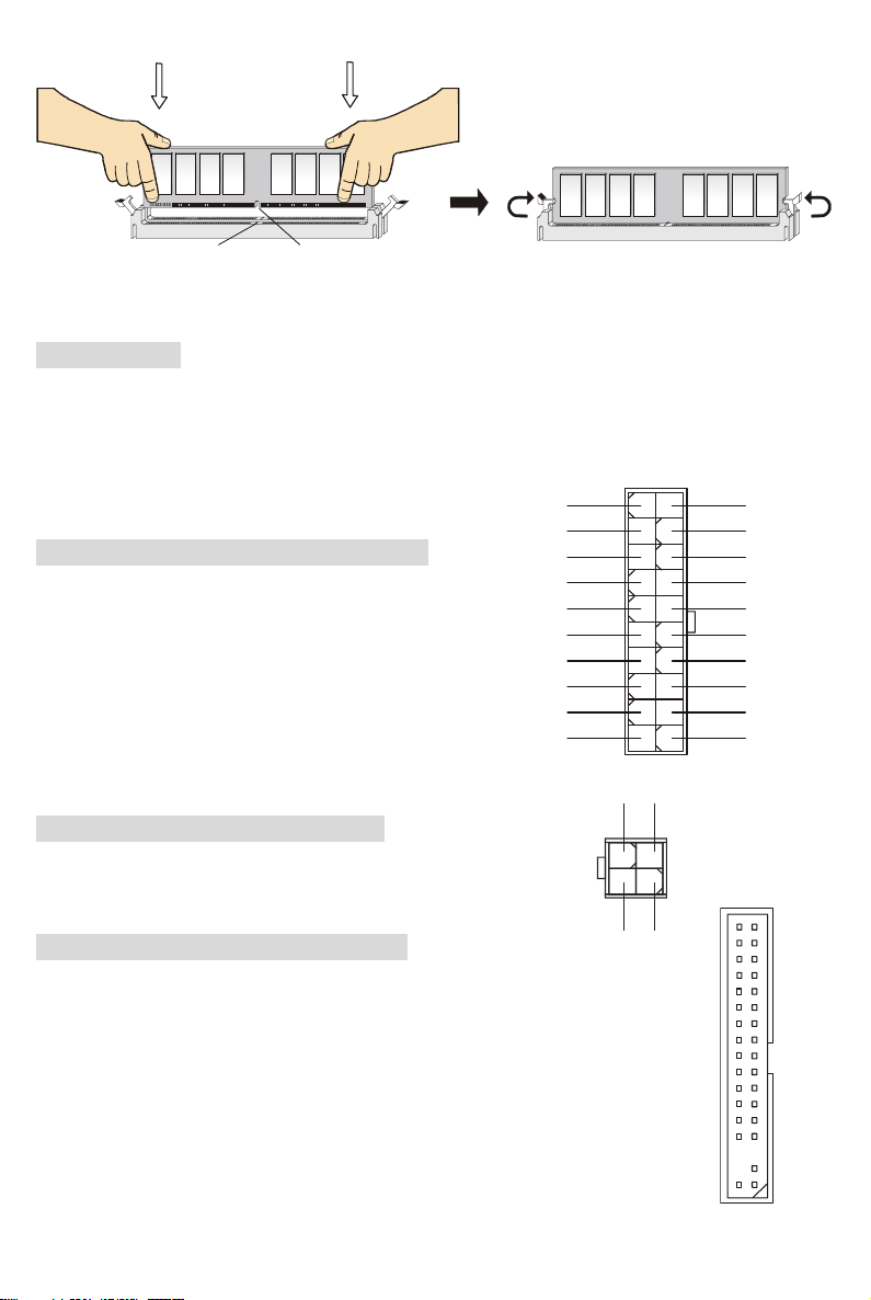
Memory
The mainboard provides two 184-pin unbuffered DDR266/DDR333/DDR400 DDR SDRAM, and
supports the memory size up to 2GB. To operate properly, at least one DIMM module must be installed.
(For the updated supporting memory modules, please visit
http://www.msi.com.tw/program/products/mainboard/mbd/pro_mbd_trp_list.php )
Install at least one DIMM module on the slots. Memory modules can be installed on the slots in any
order. You can install either single- or double-sided modules to meet your own needs.
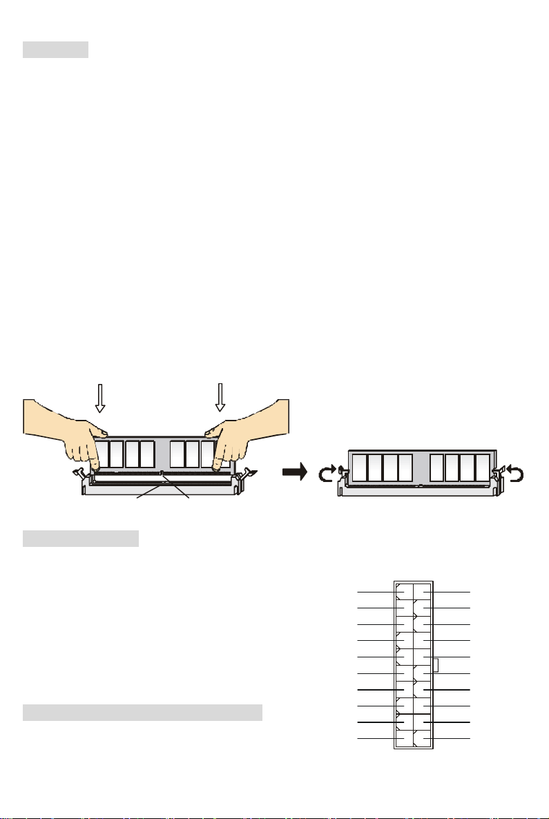
Installing DDR Modules
1. The DDR DIMM has only one notch on the center of module. The module will only fit in the right
orientation.
2. Insert the DIMM memory module vertically into the DIMM slot. Then push it in until the golden
finger on the memory module is deeply inserted in the socket.
3. The plastic clip at each side of the DIMM slot will automatically close.
8
NotchVolt
Power Supply
The mainboard supports ATX power supply for the power system. Before inserting the power supply
connector, always make sure that all components are installed properly to ensure that no damage will
be caused. A 300W or above power supply is suggested.
ATX 20-Pin Power Connector: CONN1
This connector allows you to connect to an ATX power supply.
To connect to the ATX power supply, make sure the plug of
the power supply is inserted in the proper orientation and the
pins are aligned. Then push down the power supply firmly
into the connector.
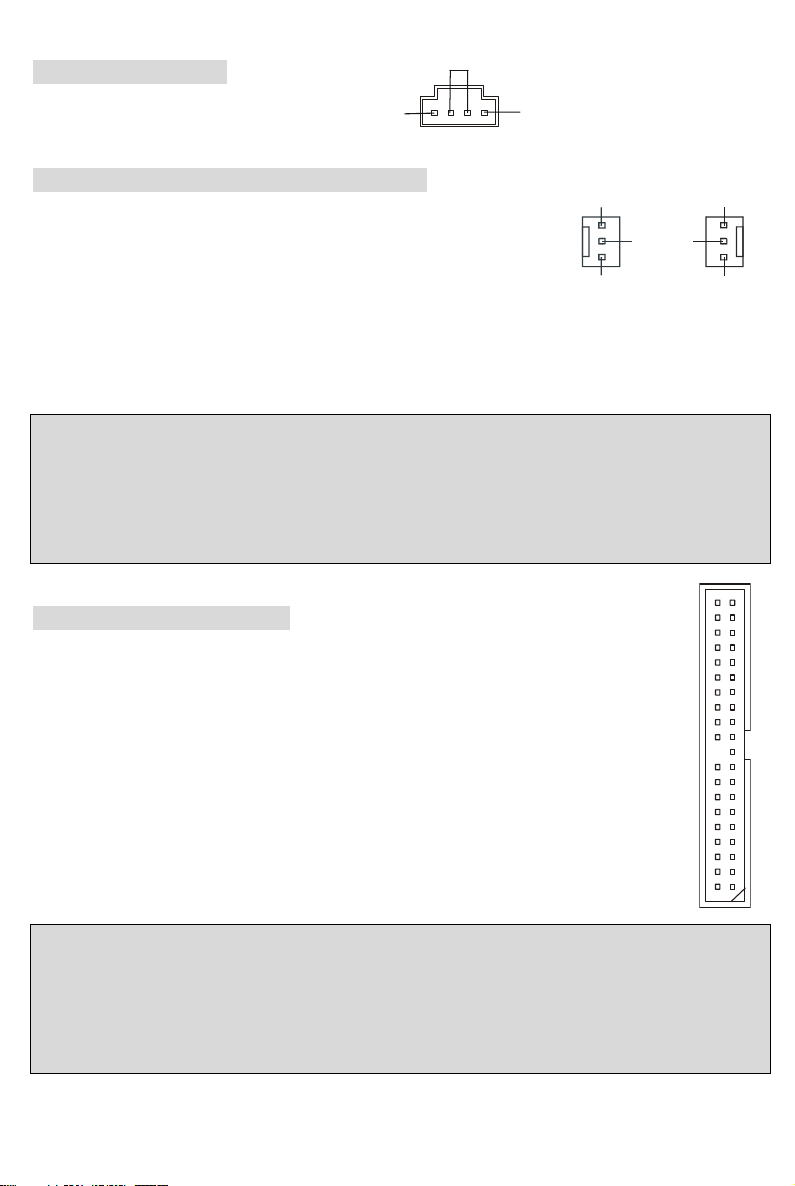
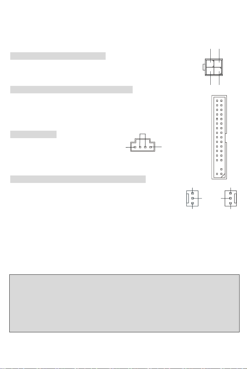
ATX 12V Power Connector: JPW1
This 12V power connector is used to provide power to the CPU.
Floppy Disk Drive Connector: FDD1
The mainboard provides a standard floppy disk drive connector that supports 360K,
720K, 1.2M, 1.44M and 2.88M floppy disk types.
3.3V
-12V
GND
GND
PW_OK
-5V
5V_SB
5V
12V
PS_O
N
10 20
111
GND
GND
5V
GND
GND
GND
5V
5V
3.3V
3.3V
1
3
2
4
G
ND
GND
12V
12V
9
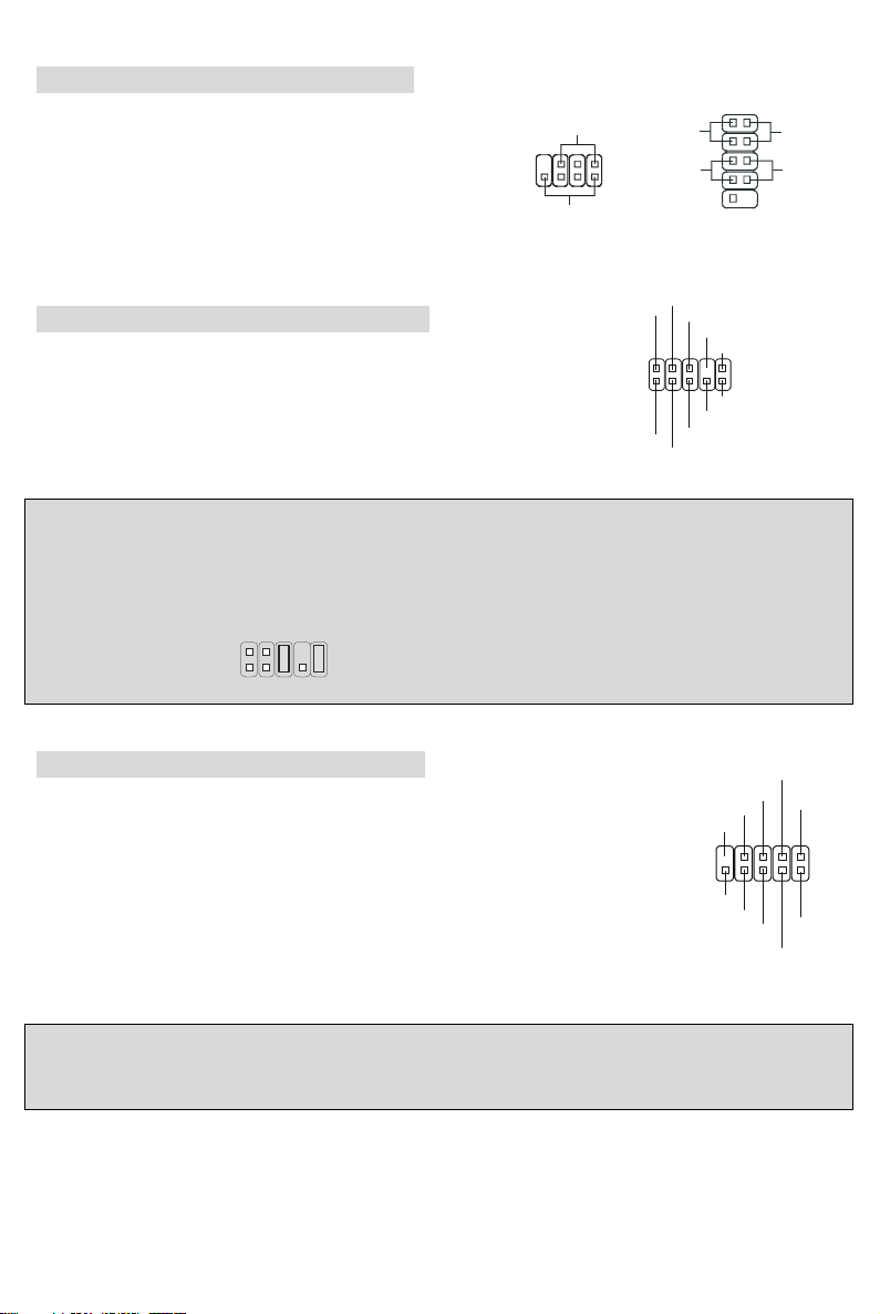
CD-In Connector: J1
The connector is for CD-ROM audio connector.
Fan Power Connectors: CPUFAN1/SFAN1
The CPUFAN1 (processor fan) and SFAN1 (system fan) support system
cooling fan with +12V. They support three-pin head connector. When
connecting the wire to the connectors, always take note that the red wire
is the positive and should be connected to the +12V, the black wire is Ground and should be connected
to GND. If the mainboard has a System Hardware Monitor chipset on-board, you must use a specially
designed fan with speed sensor to take advantage of the CPU fan control.
MSI Reminds You...
1. Always consult the vendors for proper CPU cooling fan.
2. CPUFAN1 supports the fan control. You can install the PC Alert utility that will automatically control
the CPU fan speed according to the actual CPU temperature.
IDE Connectors: IDE1/IDE2
The mainboard has a 32-bit Enhanced PCI IDE and Ultra DMA 33/66/100/133 controller that
provides PIO mode 0~4, Bus Master, and Ultra DMA 33/66/100/133 function. You can
connect up to four hard disk drives, CD-ROM, 120MB Floppy and other devices.
The first hard drive should always be connected to IDE1. IDE1 can connect a Master and a
Slave drive. You must configure second hard drive to Slave mode by setting the jumper
accordingly. IDE2 can also connect a Master and a Slave drive.
MSI Reminds You...
If you install two hard disks on cable, you must configure the second drive to Slave mode by setting its
jumper. Refer to the hard disk documentation supplied by hard disk vendors for jumper setting
instructions.
GND
L
R
+12V
GND
SENSOR
CPUFAN1
SFAN1
+12V
GND
S
EN
SO
R
10
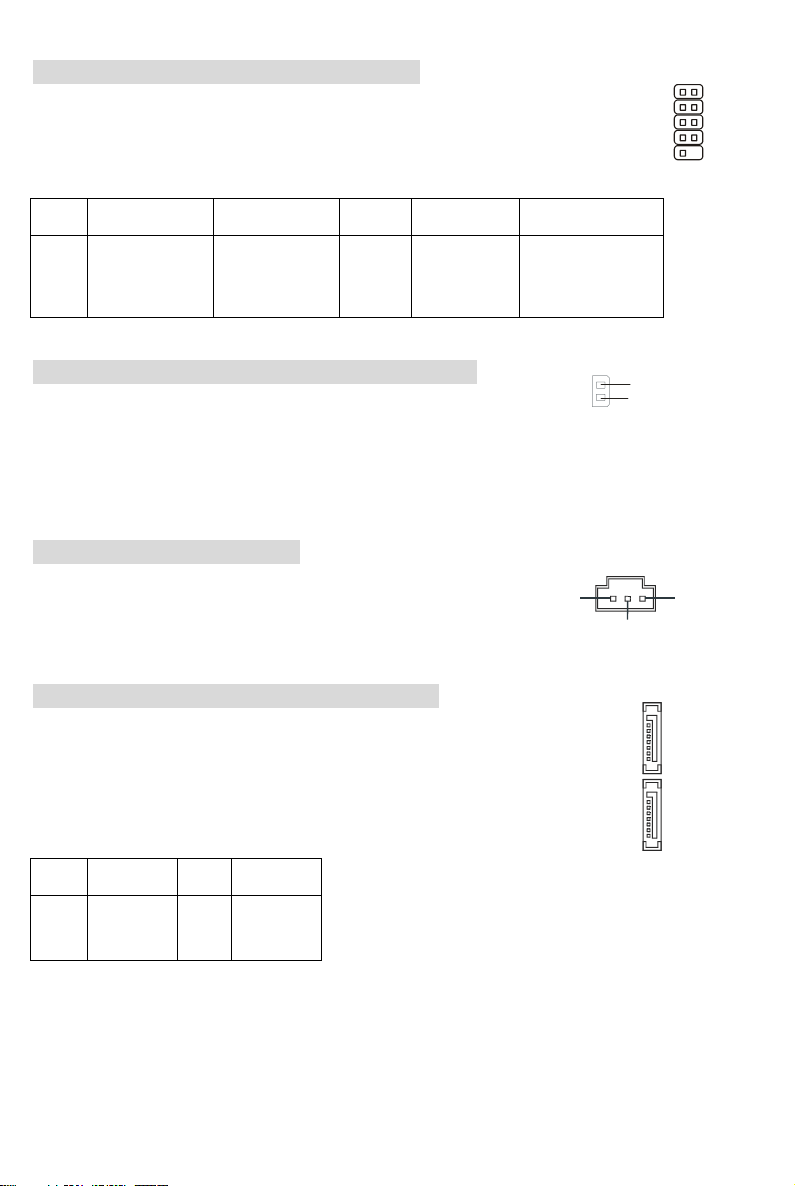
Front Panel Connectors: JFP1/JFP2
The mainboard provides two front panel connectors for
electrical connection to the front panel switches and
LEDs. JFP1 is compliant with Intel Front Panel I/O
Connectivity Design Guide.
Front Panel Audio Connector: JAUD1
The front panel audio connector allows you to connect
to the front panel audio and is compliant with Intel ®
Front Panel I/O Connectivity Design Guide.
MSI Reminds You...
If you do not want to connect to the front audio header, pins 5 & 6, 9 & 10 have to be jumpered in order
to have signal output directed to the rear audio ports. Otherwise, the Line-Out connector on the back
panel will not function.
1
2
9
10
Front USB Connector: JUSB1/JUSB2
The mainboard provides two standard USB 2.0 pin headers JUSB1&JUSB2.
USB2.0 technology increases data transfer rate up to a maximum throughput of
480Mbps, which is 40 times faster than USB 1.1, and is ideal for connecting
high-speed USB interface peripherals such as USB HDD, digital cameras, MP3
players, printers, modems and the like.
MSI Reminds You...
Note that the pins of VCC and GND must be connected correctly, or it may cause some damage.
HDD
LED
Power
LED
Reset
Switch
Powe
r
Switch
1
9
2
10
JFP1
Power
LED
Speaker
1
7
2
8
JFP2
1
2
9
10
AUD_MIC
AUD_MIC_BIAS
AUD_GND
A
UD_V
CC
AUD_FPOUT_R
AUD_RET_L
A
UD_FPOUT_
L
AUD_RET_R
NC
KEY
1
2
9
10
GND
NC
KEY
GND
VCC
VCC
U
S
B0-
B1-
USB0+
USB1+
11
Serial Port Connector: JCOM1 (Optional)
The main board offers one serial port COM2. It is 16550A high speed communication
port that sends/receives 16 bytes FIFOs. You can attach a serial mouse or other serial
device directly to it.
PIN SIGNAL DESCRIPTION PIN SIGNAL DESCRIPTION
1
2
3
4
5
DCD
SIN
SOUT
DTR
GND
Data Carry Detect
Serial In or
Receive Data
Serial Out or
Transmit Data
6
7
8
9
DSR
RTS
CTS
RI
Data Set Ready
Request To Send
Clear To Send
Ring Indicate
Chassis Intrusion Switch Connector: JCASE1
This connector is connected to 2-pin connector chassis switch. If the
Chassis is open, the switch will be short. The system will record this status. To clear the warning, you
must enter the BIOS setting and clear the status.
SPDIF-Out Connector: JSP1
This connector is used to connect SPDIF (Sony & Philips Digital
Interconnect Format) interface for digital audio transmission.
Serial ATA HDD Connectors: SATA1/SATA2
The mainboard provides dual high-speed Serial ATA interface ports. The ports
support 1
st
generation Serial ATA data rates of 150 MB/s and are fully compliant
with Serial ATA 1.0 specifications. Each Serial ATA connector can connect to 1
hard disk drive.
PIN SIGNAL PIN SIGNAL
1
3
5
7
GND
TXN
RXN
GND
2
4
6
TXP
GND
RXP
1
9
2
1
0
2
1
GND
CINTRO
GN
D
PDIF
VCC
SATA1
SATA2
1
7
1
7
12
Clear CMOS Jumper: JBAT1
There is a CMOS RAM on board that has a power supply from external
battery to keep the data of system configuration. With the CMOS
RAM, the system can automatically boot OS every time it is turned on. If you want to clear the system
configuration, use the JBAT1 (Clear CMOS Jumper) to clear data. Follow the instructions below to clear
the data:
MSI Reminds You...
You can clear CMOS by shorting 2-3 pin while the system is off. Then return to 1-2 pin position. Avoid
clearing the CMOS while the system is on; it will damage the mainboard.
AGP (Accelerated Graphics Port) Slot
The AGP slot allows you to insert the AGP
graphics card. AGP is an interface specification designed for the throughput demands of 3D graphics. It
introduces a 66MHz, 32-bit channel for the graphics controller to directly access main memory.
PCI (Peripheral Component Interconnect) Slots
The PCI slots allow you to insert the expansion cards to meet your needs. When adding or removing
expansion cards, make sure that you unplug the power
supply first. Meanwhile, read the documentation for the expansion card to make any necessary
hardware or software settings for the expansion card, such as jumpers, switches or BIOS configuration.
PCI Interrupt Request Routing
The IRQ, abbreviation of interrupt request line and pronounced I-R-Q, are hardware lines over which
devices can send interrupt signals to the microprocessor. The PCI IRQ pins are typically connected to
the PCI bus INT A# ~ INT D# pins as follows:
Order1 Order2 Order3 Order4
PCI Slot 1 INT A# INT B# INT C# INT D#
PCI Slot 2 INT B# INT C# INT D# INT A#
PCI Slot 3 INT C# INT D# INT A# INT B#
1
Keep Data
Clear Data
1
3
1
3
13
BIOS Setup
Power on the computer and the system will start POST (Power On Self Test) process. When the
message below appears on the screen, press <DEL> key to enter Setup.
DEL: Setup F11: Boot Menu TAB: Logo
If the message disappears before you respond and you still wish to enter Setup, restart the system by
turning it OFF and On or pressing the RESET button. You may also restart the system by
simultaneously pressing <Ctrl>, <Alt>, and <Delete> keys.
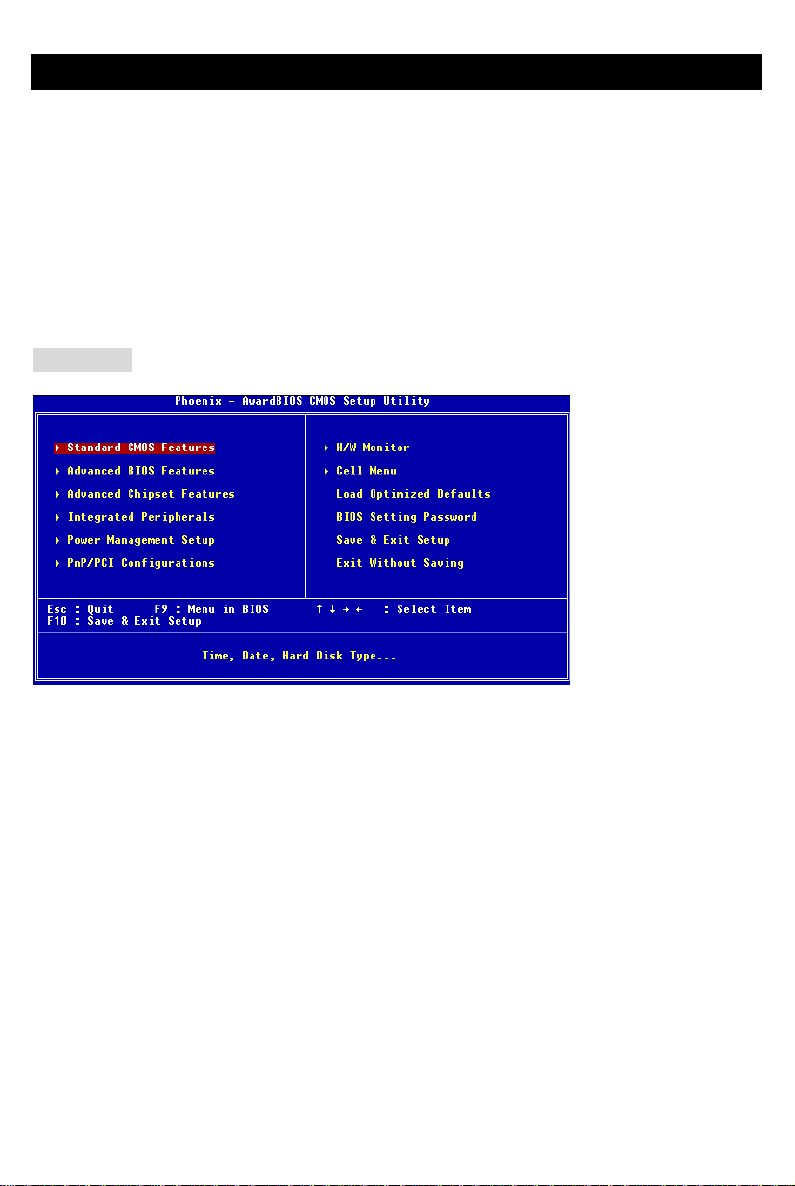
Main Page
Standard CMOS Features
Use this menu for basic system configurations, such as time, date etc.
Advanced BIOS Features
Use this menu to setup the items of Award special enhanced features.
Advanced Chipset Features
Use this menu to change the values in the chipset registers and optimize your system performance.
Integrated Peripherals
Use this menu to specify your settings for integrated peripherals.
Power Management Setup
Use this menu to specify your settings for power management.
PNP/PCI Configurations
This entry appears if your system supports PnP/PCI.
H/W Monitor
This entry shows the status of your CPU, fan, warning for overall system status.
Cell Menu
Use this menu to specify your settings for frequency/voltage control.

14
Load Optimized Defaults
Use this menu to load factory default settings into the BIOS for stable system performance operations.
BIOS Setting Password
Use this menu to set BIOS setting Password.
Save & Exit Setup
Save changes to CMOS and exit setup.
Exit Without Saving
Abandon all changes and exit setup.
15
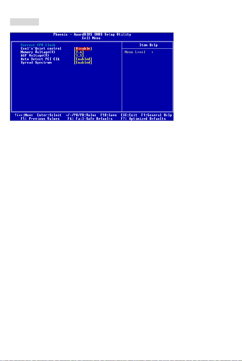
Cell Menu
Current CPU Clock
It shows the current clock of CPU. Read-only.
Cool’n’Quiet control
It provides a CPU temperature detecting function to prevent your CPU’s from overheading due to the
heavy working loading.
Memory Voltage (V)
Adjusting the DDR voltage can increase the DDR speed. Any changes made to this setting may
cause a stability issue, so changing the DDR voltage for long-term purpose is NOT recommended.
AGP Voltage (V)
AGP voltage is adjustable in the field, allowing you to increase the performance of your AGP display
card when overclocking, but the stability may be affected. Setting options: 1.5V to 1.85V at 0.05V
increment.
Auto Detect PCI Clk
This item is used to auto detect the PCI slots. When set to [Enabled], the system will remove (turn off)
clocks from empty PCI slots to minimize the electromagnetic interference (EMI).
Spread Spectrum
When the motherboard’s clock generator pulses, the extreme values (spikes) of the pulses creates EMI
(Electromagnetic Interference). The Spread Spectrum function reduces the EMI generated by
modulating the pulses so that the spikes of the pulses are reduced to flatter curves. If you do not have
any EMI problem, leave the setting at Disabled for optimal system stability and performance. But if you
are plagued by EMI, set to Enabled for EMI reduction. Remember to disable Spread Spectrum if you
are overclocking because even a slight jitter can introduce a temporary boost in clock speed which may
just cause your overclocked processor to lock up.

16
17
Einführung
Danke, dass Sie das K8MM-V Series (MS-7142 V1.X) Micro ATX Mainboard erworben haben. Dieses
Mainboard basiert auf den VIA ® K8M800-CE und VT8237R Chipsätzen und ermöglicht so ein
optimales und effizientes System. Entworfen, um die fortschrittlichen AMD ® K8 Athlon64 Prozessoren
im 754 Pin- Package aufzunehmen, stellt das K8MM-V Series die ideale Lösung zum Aufbau eines
professionellen Hochleistungsdesktopsystems dar.
Layout
SFAN1
CPUFAN1
JPW1
F
D
D
1
SATA1
SATA2
T:
M:
B:
Line-In
Line-Out
Mic
T: L AN ja ck
B: USB ports
Winbond
W83627THF
VIA
K8M800-CE
BATT
+
D
D
R
1
D
D
R
2
JWR2
JCASE1
I
D
E
1
I
D
E
2
JFP1
JFP2
JBAT1
JAUD1
J1
Top : Pa rall el Por t
Bottom:
COM A
VGA Port
Top : mo use
Bottom: keyboard
USB ports
BIOS
AGP Slot
PCI S lot 3
PCI S lot 2
PCI S lot 1
JUSB1
JUSB2
JCOM1
(Optional)
Codec
VIA
VT6103L
JSP1
VIA
VT8237R

18
Spezifikationen
CPU
z Unterstützt 64-Bit AMD®K8 Athlon64 Prozessoren (Sockel 754)
z Unterstützt 3700+ CPUs und höher
(Um die neuesten Informationen zu unterstützten Prozessoren zu erhalten, besuchen Sie bitte
http://www.msi.com.tw/program/products/mainboard/mbd/pro_mbd_cpu_support.php )
Chipsatz
z VIA®K8M800-CE Chipsatz
- HyperTransport
TM
Anbindung an den AMD K8 Athlon64 Prozessor
- Bidirektionale Übertragung von Adress-/Steuerinformationen und Daten mit 8 oder 16 Bit
- 800/600/400/200 MHz “Double Data Rate” Betrieb in beiden Richtungen
- erfüllt AGP V3.0 mit 8x Übertragungsmodus
- Grafik integriert
z VIA®VT8237R Chipsatz (487 BGA)
- Verfügt über eine eingebauten Dual Channel SATA Kontroller mit bis zu 150MB/s.
- Hardware Sound Blaster/Direct Sound AC97 Audiolösung integriert
- Ultra DMA 66/100/133 Master Mode PCI EIDE Kontroller
- Erweiterte Stromsparfunktionalität gemäß ACPI und PC2001
- Unterstützt USB 2.0 mit bis zu 8 Anschlüssen
- Unterstützt RAID0 oder RAID1
Hauptspeicher
z Unterstützt DDR266/333/400 DDR SDRAM für zwei 184-pin DDR DIMMs.
z Unterstützt den Speicherausbau auf bis zu 2GB
(Um den letzten Stand bezüglich der unterstützten Speichermodule zu erhalten, besuchen Sie bitte
http://www.msi.com.tw/program/products/mainboard/mbd/pro_mbd_trp_list.php )
Schnittstellen
z Ein AGP (Accelerated Graphics Port) Slot.
-erfüllt die Spezifikation AGP 3.0
z Drei 32-Bit Master 3,3V/5V PCI Bus Sockel

19
Onboard IDE
z Der im VIA®VT8237R Chipsatz enthaltene IDE Kontroller bietet für den Festplatten- und
CD-ROM-Zugriff PIO, Bus Mastering und Betrieb mit Ultra DMA 66/100/133
z Bis zu vier IDE Geräte anschließbar
z Serial ATA/150 Kontroller in den VT8237R integriert
- Übertragungsrate von bis zu 150MB/s
- Bis zu zwei Serial ATA Laufwerke anschließbar
Peripherieanschlüsse onboard
z hierzu gehören:
- 1 Anschluss für ein Diskettenlaufwerke mit 360 KB, 720 KB, 1,2 MB, 1,44 MB oder 2,88 MB
- 1 Serielle Schnittstelle (COM A)
- 1 VGA Anschluss
- 1 Parallele Schnittstelle, die die Betriebsmodi SPP/EPP/ECP unterstützt
- 8 USB 2.0 Anschlüsse (4 hintere/ 4 vordere)
- 1 Satz Audioanschlüsse (Eingang/ Ausgang/ Mikrofon).
- 1 RJ45 LAN Buchse
- 2 IDE Anschlüsse für 4 IDE Laufwerke
- 2 Serial ATA Schnittstellen
- 1 Stiftleiste JCOM1 (Optional)
Audio
z 6 Kanal Software Audio Codec VIA VT1617A.
- Erfüllt die Anforderungen der Spezifikationen gemäß AC97 V2.3.
- Genügt den Audioleistungsanforderungen gemäß PC2001.
LAN
z VIA®VT6103L 10/100 MB/s phy.
- Erfüllt PCI V2.2
- Unterstützt ACPI Stromsparfunktionalität

20
BIOS
z Das Mainboard- BIOS verfügt über “Plug & Play”- Funktionalität, mit der angeschlossene
Peripheriegeräte und Erweiterungskarten automatisch erkannt werden.
z Das Mainboard stellt ein Desktop - Management - Interface (DMI) zur Verfügung, welches
automatisch die Spezifikationen Ihres Mainboards aufzeichnet.
Abmessungen
z Micro-ATX Form Faktor: 243mm x 195mm
Montage
z 6 Montagebohrungen
21
Hinteres Anschlusspaneel
Das hintere Paneel verfügt über folgende Anschlüsse:
Tastatur
USB Ports
Mau s
COM Port VGA Port
Parall ele Schn ittstel le
Line In
Line Out
Mic I n
LAN
USB Ports
Hardware Setup
Dieses Kapitel informiert Sie darüber, wie Sie die CPU, Speichermodule und Erweiterungskarten
einbauen, des weiteren darüber, wie die Steckbrücken auf dem Mainboard gesetzt werden. Zudem
bietet es Hinweise darauf, wie Sie Peripheriegeräte anschließen, wie z.B. Maus, Tastatur, usw.
Handhaben Sie die Komponenten während des Einbaus vorsichtig und halten Sie sich an die
vorgegebene Vorgehensweise beim Einbau.
Hauptprozessor: CPU
Das Mainboard unterstützt Intel AMD ® Athlon64 Prozessoren, um den Einbau der CPU zu erleichtern ,
wird der Sockel –754 verwendet. Achten Sie beim Einbau bitte darauf, dass die CPU immer mit einem
Kühlkörper mit aktivem Prozessorlüfter versehen sein muss, um Überhitzung zu vermeiden. Verfügen
Sie über keinen Kühlkörper mit aktivem Prozessorlüfter, setzen Sie sich bitte mit Ihrem Händler in
Verbindung, um einen solchen zu erwerben und danach zu installieren, bevor Sie Ihren Computer
anschalten.
(Um die neuesten Informationen zu unterstützten Prozessoren zu erhalten, besuchen Sie bitte
http://www.msi.com.tw/program/products/mainboard/mbd/pro_mbd_cpu_support.php)
22
Beispiel zur Ermittlung des Kerntaktes
Wenn externer CPU-Takt = 200 MHz
Kern-/Systemtaktmultiplikator = 12
dann ist Kerntakt = externer CPU-Takt x Kern/Sytemtaktmultiplikator
= 200 MHz x 12
= 2,4 GHz
Tabelle unterstützte Speichergeschwindigkeit/CPU FSB
Speicher
FSB
DDR 266 DDR 333 DDR 400
800 MHz OK OK OK
Vorgehensweise beim CPU-Einbau beim Sockel 754
1. Bitte schalten Sie das System aus und ziehen Sie den Netzstecker, bevor Sie die CPU
einbauen.
2. Ziehen Sie den Hebel leicht seitlich weg vom Sockel, heben Sie ihn danach bis zu einem Winkel
von 90° an.
3. Machen Sie den goldenen Pfeil ausfindig. Die CPU passt nur in der korrekten Ausrichtung.
Senken Sie die CPU in den Sockel.
4. Ist die CPU korrekt installiert, sollten die Pins an der Unterseite vollständig versenkt und nicht
mehr sichtbar sein. Beachten Sie bitte, dass jede Abweichung von der richtigen Vorgehensweise
beim Einbau Ihr Mainboard dauerhaft beschädigen kann.
5. Drücken Sie die CPU fest in den Sockel und drücken Sie den Hebel wieder nach unten bis in
seine Ursprungsstellung. Da die CPU während des Schließens des Hebels dazu neigt, sich zu
bewegen, sichern Sie diese bitte während des Vorgangs durch permanenten Fingerdruck von
oben, um sicherzustellen, dass die CPU richtig und vollständig im Sockel sitzt.

23
Installation des AMD Athlon64 CPU Kühlersets
Wenn Sie die CPU einbauen, stellen Sie bitte sicher, dass Sie auf der CPU einen Kühlkörper mit
aktiven Prozessorlüfter anbringen, um Überhitzung zu vermeiden. Verfügen Sie über keinen aktiven
Prozessorlüfter mit Kühlkörper, setzen Sie sich bitte mit Ihrem Händler in Verbindung, um einen
solchen zu erwerben und zu installieren, bevor Sie Ihren Computer anschalten.
1. Ziehen Sie die Schutzfolie von der Klebstoffschicht der Rückplatte ab
2. Drehen Sie das Mainboard um und bringen Sie die Rückplatte an der geeigneten Stelle an.
3. Drehen Sie das Mainboard wieder auf die Vorderseite und legen Sie es auf einer ebenen Fläche
ab. Machen Sie die zwei Bohrungen auf dem Mainboard ausfindig.
4. Richten Sie den Rückhaltemechanismus und die Rückplatte aufeinander aus. Sichern Sie beide
mit zwei Schrauben gegeneinander.
5. Setzen Sie das Kühlerset auf den Rückhaltemechanismus. Haken Sie zuerst ein Ende des
Haltebügels ein.
6. Drücken Sie das andere Ende des Bügels herunter, um das Kühlerset auf dem
Rückhaltemechanismus zu befestigen.
7. Machen Sie den Sicherungshebel, den Sicherungshaken und den Sicherungsbolzen ausfindig.
Heben sie den gut befestigten Hebel an.
8. Drücken Sie den Sicherungshebel herab.
9. Stellen Sie sicher, dass der Sicherungshaken den Sicherungsbolzen des
Rückhaltemechanismus vollständig umschließt.
MSI weist darauf hin...
Es besteht Verletzungsgefahr, wenn Sie den Sicherungshaken vom Sicherungsbolzen trennen. Sobald
der Sicherungshaken gelöst wird, schnellt der Sicherungshaken sofort zurück.
24
Speicher
Das Mainboard bietet zwei Plätze für 184-Pin ungepufferte DDR266/DDR333/DDR400 DDR SDRAM
DIMM Speichermodule und unterstützt den Speicherausbau auf bis zu 2GB. Setzen Sie für den
ordnungsgemäßen Betrieb mindestens ein DIMM- Speichermodul ein.
Um den letzten Stand bezüglich der unterstützten Speichermodule zu erhalten, besuchen Sie bitte
http://www.msi.com.tw/program/products/mainboard/mbd/pro_mbd_trp_list.php
Setzen Sie mindestens ein DIMM- Speichermodul ein. Gemäß Ihren Anforderungen können Sie
entweder ein- oder doppelseitige Module in beliebiger Reihenfolge verwenden .
Vorgehensweise beim Einbau von DDR Modulen
1. DDR DIMMs haben nur eine Kerbe in der Mitte des Moduls. Sie passen nur in einer Richtung in
den Sockel.
2. Setzen Sie den DIMM- Speicherbaustein senkrecht in den DIMM- Sockel, dann drücken Sie ihn
hinein, bis die goldenen Kontakte tief im Sockel sitzen.
3. Die Plastikklammern an den Seiten des DIMM- Sockels schließen sich automatisch.
KerbeVolt
Stromversorgung
Das Mainboard unterstützt zur Stromversorgung ATX
Netzteile. Bevor Sie den Netzteilstecker einstecken, stellen
Sie stets sicher, dass alle Komponenten ordnungsgemäß
eingebaut sind, um Schäden auszuschließen. Es wird ein
Netzteil mit 300W oder mehr empfohlen.
ATX 20-Pin Stromanschluss: CONN1
Hier können Sie ein ATX Netzteil anschließen. Wenn Sie die
3.3V
-12V
GND
GND
PW_OK
-5V
5V_SB
5V
12V
PS_O
N
10 20
111
GND
GND
5V
GND
GND
GND
5V
5V
3.3V
3.3V
25
Verbindung herstellen, stellen Sie sicher, dass der Stecker in der korrekten Ausrichtung eingesteckt
wird und die Pins ausgerichtet sind. Drücken Sie dann den Netzteilstecker fest in den Steckersockel.
ATX 12V Stromanschluss: JPW1
Dieser 12V Stromanschluss wird verwendet, um die CPU mit Strom zu versorgen.
Anschluss des Diskettenlaufwerks: FDD1
Das Mainboard verfügt über einen Standardanschluss für Diskettenlaufwerke mit 360 KB,
720 KB, 1,2 MB, 1,44 MB oder 2,88 MB Kapazität.
CD-Eingang: J1
Hier kann das Audiokabel des CD-ROM
Laufwerkes angeschlossen werden.
Stromanschlüsse für Lüfter: CPUFAN1/SFAN1
Die dreipoligen Anschlüsse CPUFAN1 (Prozessorlüfter) und SFAN1
(Systemlüfter) unterstützen aktive Systemlüfter mit + 12V. Wenn Sie den
Stecker mit dem Anschluss verbinden, sollten Sie immer darauf achten, dass
der rote Draht der positive Pol ist und mit +12V verbunden werden sollte, der schwarze Draht ist der
Erdkontakt und sollte mit GND verbunden werden. Ist Ihr Mainboard mit einem Chipsatz zur
Überwachung der Systemhardware und Steuerung der Lüfter versehen, dann brauchen Sie einen
speziellen Lüfter mit Tacho, um diese Funktion zu nutzen.
MSI weist darauf hin...
1. Bitten Sie stets Ihren Händler bei der Auswahl des geeigneten CPU Kühlers um Hilfe.
2. CPUFAN1 unterstützen Lüftersteuerung. Sie können das Utility „PC Alert” installieren, das die
Geschwindigkeit des Prozessorlüfters automatisch in Abhängigkeit von der tatsächlichen CPU
Temperatur steuert.
1
3
2
4
G
ND
GND
12V
12V
GND
L
R
+12V
GND
SENSOR
CPUFAN1
SFAN1
+12V
GND
S
EN
SO
R
 Loading...