


TM-RG2M
Table of contents
 Loading...
General-Purpose AC Servo
MODEL
TM-RFM
TM-RG2M
TM-RU2M
DIRECT DRIVE MOTOR INSTRUCTION MANUAL
H
A - 1
Safety Instructions
Please read the instructions carefully before using the equipment.
To use the equipment correctly, do not attempt to install, operate, maintain or inspect the equipment until you
have read through this Instruction Manual and appended documents carefully. Do not use the equipment
until you have a full knowledge of the equipment, safety information and instructions.
In this Instruction Manual, the safety instruction levels are classified into "WARNING" and "CAUTION".
WARNING
Indicates that incorrect handling may cause hazardous conditions,
resulting in death or severe injury.
CAUTION
Indicates that incorrect handling may cause hazardous conditions,
resulting in medium or slight injury to personnel or may cause physical
damage.
Note that the CAUTION level may lead to a serious consequence according to conditions.
Please follow the instructions of both levels because they are important to personnel safety.
What must not be done and what must be done are indicated by the following diagrammatic symbols.
Indicates what must not be done. For example, "No Fire" is indicated by
.
Indicates what must be done. For example, grounding is indicated by
.
In this Instruction Manual, instructions at a lower level than the above, instructions for other functions, and so
on are classified into "POINT".
After reading this Instruction Manual, keep it accessible to the operator.
A - 2
1. To prevent electric shock, note the following
WARNING
Before wiring and inspections, turn off the power and wait for 15 minutes or more until the charge lamp
turns off. Otherwise, an electric shock may occur. In addition, when confirming whether the charge lamp
is off or not, always confirm it from the front of the servo amplifier. Then, confirm that the voltage
between P+ and N- is safe with a voltage tester and others.
Ground the servo amplifier and direct drive motor securely.
Any person who is involved in wiring and inspection should be fully competent to do the work.
Do not attempt to wire the servo amplifier and direct drive motor until they have been installed.
Otherwise, it may cause an electric shock.
The cables should not be damaged, stressed, loaded, or pinched. Otherwise, it may cause an electric
shock.
To avoid an electric shock, insulate the connections of the power supply terminals.
2. To prevent fire, note the following
CAUTION
Install the servo amplifier, direct drive motor, and regenerative resistor on incombustible material.
Installing them directly or close to combustibles will lead to a fire or smoke generation.
Provide adequate protection to prevent screws and other conductive matter, oil and other combustible
matter from entering the servo amplifier and direct drive motor.
3. To prevent injury, note the following
CAUTION
Only the power/signal specified in the Instruction Manual should be applied to each terminal. Otherwise,
it may cause an electric shock, fire, injury, etc.
Connect cables to the correct terminals. Otherwise, a burst, damage, etc. may occur.
Ensure that polarity (+/-) is correct. Otherwise, a burst, damage, etc. may occur.
The servo amplifier heat sink, regenerative resistor, direct drive motor, etc. may be hot while power is on
or for some time after power-off. Take safety measures, e.g. provide covers, to avoid accidentally
touching the parts (cables, etc.) by hand.
During operation, never touch the rotor of the direct drive motor. Otherwise, it may cause injury.
A - 3
4. Additional instructions
The following instructions should also be fully noted. Incorrect handling may cause a malfunction, injury,
electric shock, fire, etc.
(1) Transportation and installation
CAUTION
Transport the products correctly according to their mass.
Stacking in excess of the specified number of product packages is not allowed.
Do not hold the cables, rotor, encoder, or connector when carrying the direct drive motor. Otherwise, it
may drop.
Install the servo amplifier and the direct drive motor in a load-bearing place in accordance with the
Instruction Manual.
Do not get on or put heavy load on the equipment. Otherwise, it may cause injury.
The equipment must be installed in the specified direction.
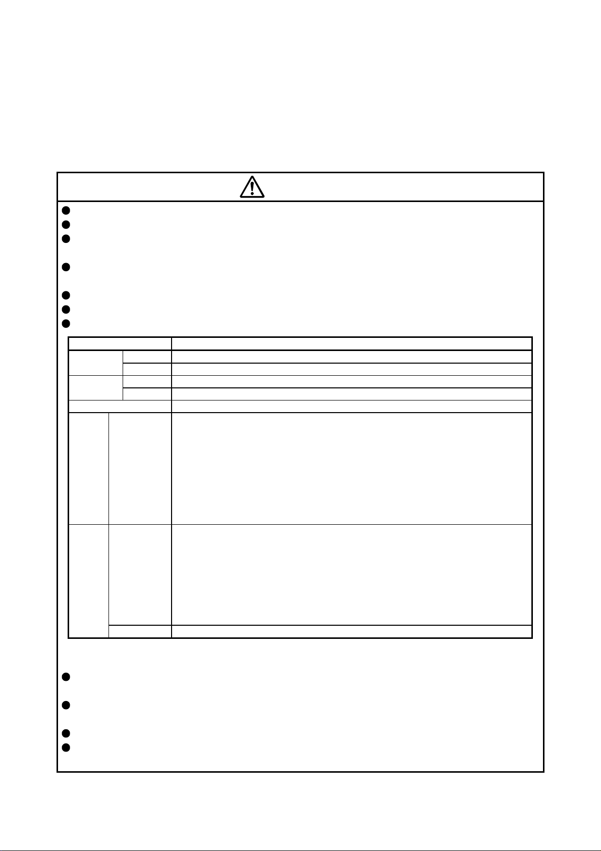
When you keep or use the equipment, please fulfill the following environment.
Item Environment
Ambient
temperature
Operation 0 °C to 40 °C (non-freezing)
Storage -15 °C to 70 °C (non-freezing)
Ambient
humidity
Operation 10 %RH to 80 %RH (non-condensing)
Storage 10 %RH to 90 %RH (non-condensing)
Ambience Indoors (no direct sunlight); no corrosive gas, inflammable gas, oil mist, dust, and dirt
Altitude
TM-RFM_J10
TM-RFM_C20
TM-RFM_E20
TM-RFM_G20
TM-RG2M_C30
TM-RG2M_E30
TM-RG2M_G30
TM-RU2M_C30
TM-RU2M_E30
TM-RU2M_G30
Max. 2000 m above sea level (Note)
Vibration
resistance
TM-RFM_C20
TM-RFM_E20
TM-RFM_G20
TM-RG2M_C30
TM-RG2M_E30
TM-RG2M_G30
TM-RU2M_C30
TM-RU2M_E30
TM-RU2M_G30
X, Y: 49 m/s
2
TM-RFM_J10 X, Y: 24.5 m/s
2
Note. Contact your local sales office for the altitude for options.
Securely fix the direct drive motor to the machine. If being attached insecurely, the motor may come off
during operation.
Do not install or operate a servo amplifier or direct drive motor, which has been damaged or has any
parts missing.
Do not drop or strike the direct drive motor. Otherwise, it may cause injury, malfunction, etc.
Take safety measures, e.g. provide covers, to prevent accidental access to the rotor of the direct drive
motor during operation.
A - 4
CAUTION
Do not apply shocks, e.g. hit with a hammer, when coupling the rotor of the direct drive motor. Otherwise,
the encoder may malfunction.
Do not subject the rotor of the direct drive motor to more than the permissible load. Otherwise, the rotor
may break.
When the product has been stored for an extended period of time, contact your local sales office.
When handling the direct drive motor, be careful about the edged parts such as corners of the direct
drive motor.
Do not strike the connector. Otherwise, it may cause a connection failure, malfunction, etc.
Be sure to check the vibration level with the direct drive motor mounted on the machine. A great vibration
may cause the early damage of a bearing and encoder. The great vibration may also cause the poor
connector connection or bolt looseness.
For the gain adjustment at the equipment startup, check the torque waveform and the speed waveform
with a measurement device to check that no vibration occurs. If the vibration occurs due to high gain, the
vibration may cause the early damage of the direct drive motor.
To prevent a fire or injury in case of an earthquake or other natural disasters, securely install, mount, and
wire the servo motor in accordance with the Instruction Manual.
(2) Wiring
CAUTION
Wire the equipment correctly and securely. Otherwise, the direct drive motor may operate unexpectedly.
Make sure to connect the cables and connectors by using the fixing screws and the locking mechanism.
Otherwise, the cables and connectors may be disconnected during operation.
Do not install a power capacitor, surge killer, or radio noise filter (FR-BIF option) on the power wire of the
direct drive motor.
To avoid a malfunction, connect the power phases (U/V/W) of the servo amplifier and the direct drive
motor correctly.
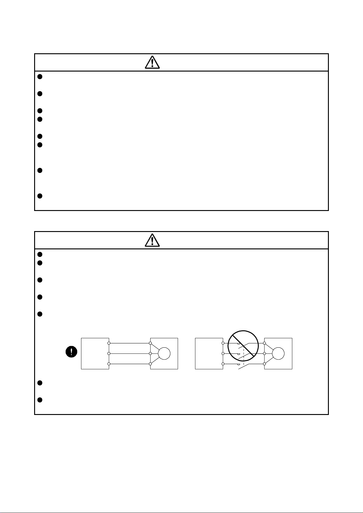
Connect the servo amplifier power output (U/V/W) to the direct drive motor power input (U/V/W) directly.
Do not let a magnetic contactor, etc. intervene. Otherwise, it may cause a malfunction.
Servo amplifier
Direct drive motor
Servo amplifier
Direct drive motor
U
M
V
W
U
V
W
U
M
V
W
U
V
W
Do not connect AC power supply directly to the direct drive motor. Otherwise, it may cause a
malfunction.
When the cable is not tightened enough to the terminal block, the cable or terminal block may generate
heat because of the poor contact. Be sure to tighten the cable with specified torque.
A - 5
(3) Test run and adjustment
CAUTION
Before operation, check the parameter settings. Improper settings may cause some machines to operate
unexpectedly.
Never make a drastic change to the parameter values as doing so will make the operation unstable.
(4) Usage
CAUTION
Provide an external emergency stop circuit to ensure that operation can be stopped and power switched
off immediately.
For equipment in which the moving part of the machine may collide against the load side, install a limit
switch or stopper to the end of the moving part. The machine may be damaged due to a collision.
Do not disassemble, repair, or modify the product. Otherwise, it may cause an electric shock, fire, injury,
etc. Disassembled, repaired, and/or modified products are not covered under warranty.
Use the direct drive motor with the specified servo amplifier.
Wire options and peripheral equipment, etc. correctly in the specified combination. Otherwise, it may
cause an electric shock, fire, injury, etc.
If the dynamic brake is activated at power-off, alarm occurrence, etc., do not rotate the servo motor by an
external force. Otherwise, it may cause a fire.
(5) Corrective actions
CAUTION
When it is assumed that a hazardous condition may occur due to a stop or product malfunction, use a
motor with an external brake to prevent the condition.
When any alarm has occurred, eliminate its cause, ensure safety, and deactivate the alarm before
restarting operation.
Provide an adequate protection to prevent unexpected restart after an instantaneous power failure.
After an earthquake or other natural disasters, ensure safety by checking the conditions of the
installation, mounting, wiring, and equipment before switching the power on to prevent an electric shock,
injury, or fire.
A - 6
(6) Storage
CAUTION
Note the followings when storing the direct drive motor for an extended period of time (guideline: three
months or more).
Always store the direct drive motor indoors in a clean and dry place.
If it is stored in a dusty or damp place, make adequate provision, e.g. cover the whole product.
If the insulation resistance of the winding decreases, check how to store the equipment.
Though the motor is rust-proofed before shipment using paint or rust prevention oil, rust may be
produced depending on the storage conditions or storage period.
If the direct drive is to be stored for longer than six months, apply rust prevention oil again especially to
the machine processing surfaces of the rotor, etc.
Before using the product after storage for an extended period of time, hand-turn the direct drive motor
rotor (output shaft) to confirm that nothing is wrong with the direct drive motor.
When the product has been stored for an extended period of time, contact your local sales office.
(7) General instruction
To illustrate details, the equipment in the diagrams of this Instruction Manual may have been drawn
without covers and safety guards. When the equipment is operated, the covers and safety guards must
be installed as specified. Operation must be performed in accordance with this Specifications and
Instruction Manual.
DISPOSAL OF WASTE
Please dispose a direct drive motor and other options according to your local laws and regulations.
«About the manual»
This Instruction Manual is required if you use this direct drive motor for the first time. Ensure to keep this
manual accessible to use the direct drive motor safely.
«Cables used for wiring»
The wiring cables mentioned in this Instruction Manual are selected based on the ambient temperature of
40 °C.
«U.S. customary units»
U.S. customary units are not shown in this manual. Convert the values if necessary according to the
following table.
Quantity SI (metric) unit U.S. customary unit
Mass 1 [kg] 2.2046 [lb]
Length 1 [mm] 0.03937 [inch]
Torque 1 [N•m] 141.6 [oz•inch]
Moment of inertia 1 [(× 10
-4
kg•m
2
)] 5.4675 [oz•inch
2
]
Load (thrust load/axial load) 1 [N] 0.2248 [lbf]
Temperature N [°C] × 9/5 + 32 N [°F]

1
CONTENTS
1. INTRODUCTION 1 - 1 to 1 - 2
1.1 Rating plate ...................................................................................................................................... 1 - 1
1.2 Parts identification ............................................................................................................................ 1 - 1
2. INSTALLATION 2 - 1 to 2 - 8
2.1 Equipment configuration .................................................................................................................. 2 - 2
2.2 Mounting direction............................................................................................................................ 2 - 3
2.3 Load mounting/dismounting precautions ......................................................................................... 2 - 3
2.4 Permissible load for the rotor ........................................................................................................... 2 - 3
2.5 Protection from oil and water ........................................................................................................... 2 - 4
2.6 Inspection items ............................................................................................................................... 2 - 5
2.7 Parts having service life ................................................................................................................... 2 - 5
2.8 Machine accuracies ......................................................................................................................... 2 - 6
2.9 Flange size ....................................................................................................................................... 2 - 6
2.10 Restrictions when using this product at altitudes exceeding 1000 m and up to 2000 m
above sea level .............................................................................................................................. 2 - 7
2.11 Magnetic shielding ......................................................................................................................... 2 - 7
3. CONNECTORS USED FOR DIRECT DRIVE MOTOR WIRING 3 - 1 to 3 - 4
3.1 Selection of connectors ................................................................................................................... 3 - 1
3.2 Wiring connectors (connector configurations A/B/C/D/E/F) ............................................................ 3 - 2
4. CONNECTOR DIMENSIONS 4 - 1 to 4 - 4
5. CONNECTION OF SERVO AMPLIFIER AND DIRECT DRIVE MOTOR 5 - 1 to 5 - 8
5.1 Connection instructions ................................................................................................................... 5 - 2
5.2 Direct drive motor power cable wiring diagram ............................................................................... 5 - 2
5.3 Selection example of wires .............................................................................................................. 5 - 3
5.4 Servo amplifier terminal section ....................................................................................................... 5 - 4
6. WIRING OPTION 6 - 1 to 6 -10
6.1 Connector set ................................................................................................................................... 6 - 1
6.1.1 Combinations of connector set ................................................................................................. 6 - 2
6.1.2 Connector list ............................................................................................................................ 6 - 3
6.2 Encoder connector set ..................................................................................................................... 6 - 4
6.2.1 MR-J3DDCNS ........................................................................................................................... 6 - 4
6.2.2 MR-J3DDSPS ........................................................................................................................... 6 - 5
6.2.3 Combinations for the encoder cable ......................................................................................... 6 - 5
6.2.4 Fabrication of the encoder cable ............................................................................................... 6 - 6
6.3 Absolute position storage unit MR-BTAS01 .................................................................................... 6 - 9

2
7. TM-RFM SERIES 7 - 1 to 7 -12
7.1 Model code definition ....................................................................................................................... 7 - 1
7.2 Combinations of servo amplifier and direct drive motor .................................................................. 7 - 2
7.3 Specification list ............................................................................................................................... 7 - 3
7.4 Torque characteristics ..................................................................................................................... 7 - 6
7.5 Dimensions ...................................................................................................................................... 7 - 7
8. TM-RG2M SERIES/TM-RU2M SERIES 8 - 1 to 8 -10
8.1 Model designation ............................................................................................................................ 8 - 1
8.2 Combinations of servo amplifier and direct drive motor .................................................................. 8 - 2
8.3 Specification list ............................................................................................................................... 8 - 3
8.4 Torque characteristics ..................................................................................................................... 8 - 5
8.5 Mounting method ............................................................................................................................. 8 - 5
8.6 Dimensions ...................................................................................................................................... 8 - 6
APPENDIX App. - 1 to App. - 7
App. 1 Selection example of direct drive motor ............................................................................... App. - 1
App. 2 Manufacturer list ................................................................................................................... App. - 3
App. 3 Crimping connector for CNP3_ ............................................................................................ App. - 3
App. 4 Fabrication of the encoder cable .......................................................................................... App. - 4
App. 5 Compliance with the CE marking ......................................................................................... App. - 5
App. 6 Compliance with UL/CSA standard ...................................................................................... App. - 6
1. INTRODUCTION
1 - 1
1. INTRODUCTION
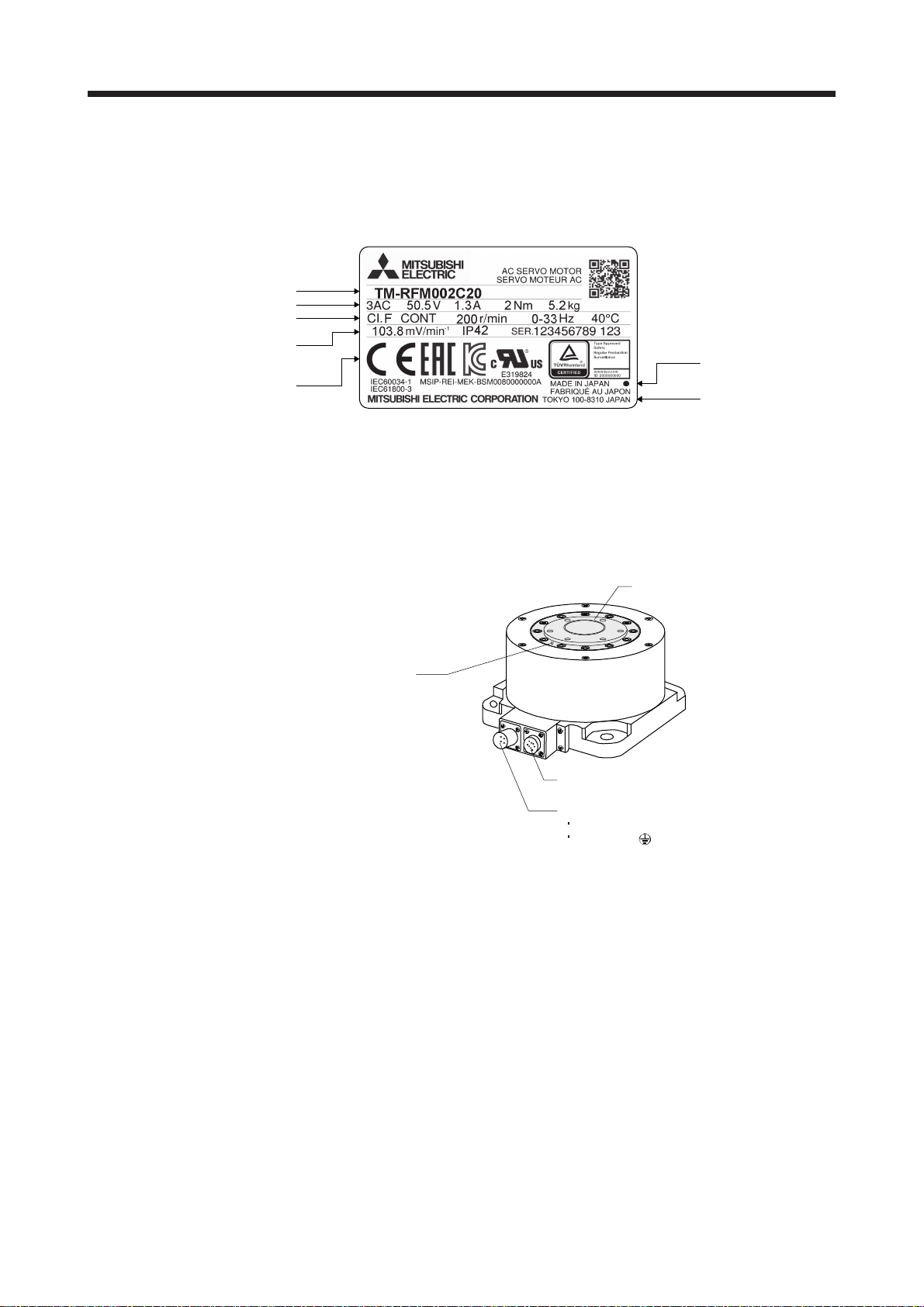
1.1 Rating plate
The following shows an example of rating plate for explanation of each item.
Model
Input power, rated torque, and mass
Insulation class, rated speed, and
maximum ambient temperature
Induced voltage constant, IP rating,
and serial number (Note 1)
(Note 2)
Manufacturer
Conforming standards,
and Country of origin
Note 1. Production year and month of the direct drive motor are indicated in a serial number on the rating plate.
The year and month are indicated by the last two digits of the year and one digit of the month [1 to 9, X (10), Y (11), and Z
(12)].
For January 2012, the Serial No. is like, "SER. _ _ _ _ _ _ _ _ _ 121".
2. Products approved by Certification Bodies are marked. The marks depends on the Certification Bodies.
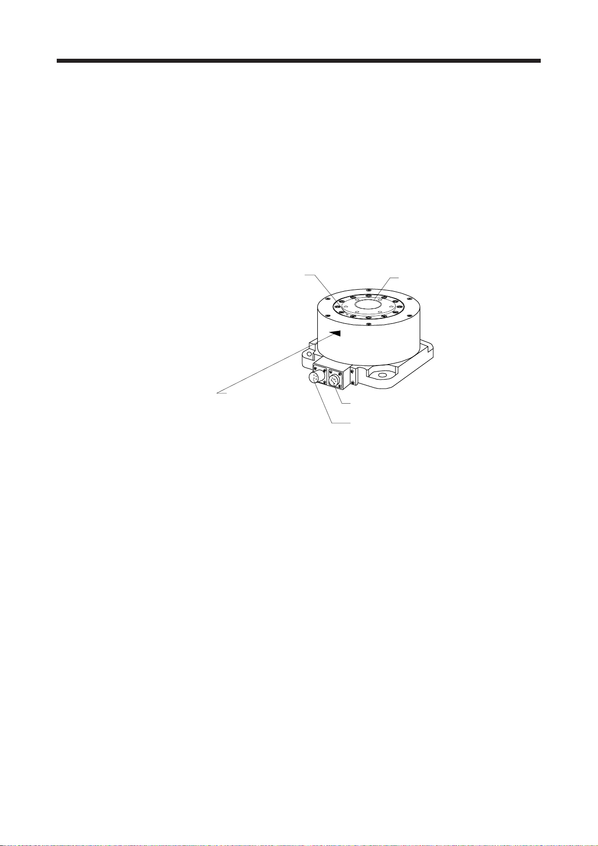
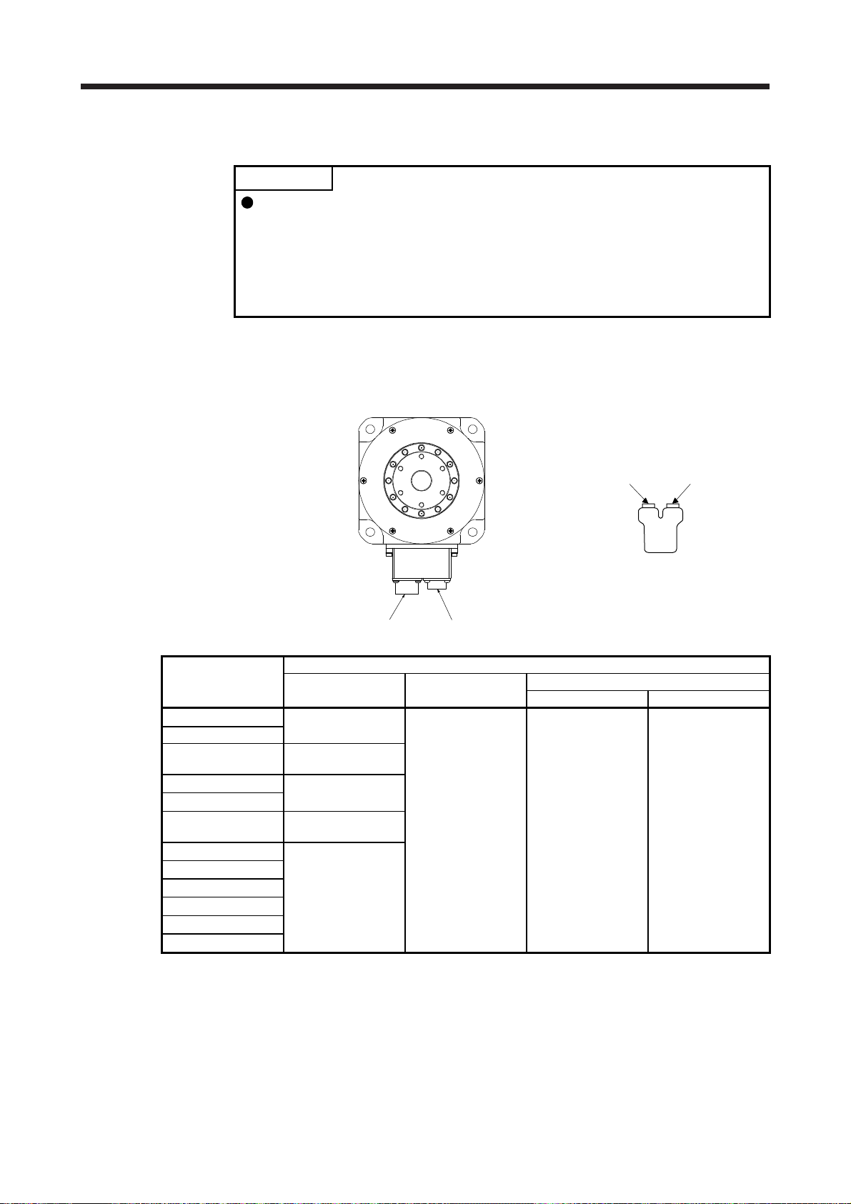
1.2 Parts identification
Rotor (output shaft)
Encoder connector
Power supply connector
Power supply (U/V/W)
Grounding ( )
Z-phase mark

1. INTRODUCTION
1 - 2
MEMO
2. INSTALLATION
2 - 1
2. INSTALLATION
WARNING
To prevent electric shock, ground each equipment securely.
CAUTION
Stacking in excess of the specified number of product packages is not allowed.
Install the direct drive motor on incombustible material. Installing them directly or
close to combustibles will lead to smoke or a fire.
Install the servo amplifier and the direct drive motor in a load-bearing place in
accordance with the Instruction Manual.
Do not get on or put heavy load on the equipment. Otherwise, it may cause injury.
Use the equipment within the specified environment. For the environment, refer to
section 7.3.
Do not drop or strike the direct drive motor as it is precision equipment.
Do not install or operate a direct drive motor, which has been damaged or has
any parts missing.
Do not hold the cables, rotor, encoder, or connector when carrying the direct drive
motor. Otherwise, it may drop.
Securely fix the direct drive motor to the machine. If being attached insecurely,
the motor may come off during operation, leading to injury.
Do not apply shocks, e.g. hit with a hammer, when coupling the rotor of the direct
drive motor. Otherwise, the encoder may malfunction.
When coupling a load to the direct drive motor, make sure to align and center the
load on the motor flange rabbet. Particularly, when a rigid coupling is used, even
a slight center deviation may reduce position accuracy or damage the rotor.
Balance the load to the extent possible. Not doing so can cause vibration during
direct drive motor operation or damage the bearings and encoder.
Take safety measures, e.g. provide covers, to prevent accidental access to the
rotor of the direct drive motor during operation.
Do not subject the rotor of the direct drive motor to more than the permissible
load. Otherwise, the rotor may break, leading to injury.
When the product has been stored for an extended period of time, contact your
local sales office.
Be sure to check the vibration level with the direct drive motor mounted on the
machine. A great vibration may cause the early damage of a bearing and
encoder. The great vibration may also cause the poor connector connection or
bolt looseness.
For the gain adjustment at the equipment startup, check the torque waveform and
the speed waveform with a measurement device to check that no vibration
occurs. If the vibration occurs due to high gain, the vibration may cause the early
damage of the direct drive motor.
Do not use the direct drive motor where the shaft-through portion may be subject
to pressure (e.g. compressed air). Applying air pressure to the inside of the direct
drive motor may cause a malfunction.
2. INSTALLATION
2 - 2
2.1 Equipment configuration
The following shows the configuration of a direct drive motor. When using the direct drive motor, note the
following.
(1) Minimum oscillation angle
If the direct drive motor rotates repeatedly by a small angle (by 70
or less), make the direct drive motor
rotate by 90
or more at least once a day in order to keep the bearing lubricated.
(2) Z-phase position
A Z-phase pulse turns on (Z-phase mark passing) when the Z-phase mark on the rotor end of the direct
drive motor passes over the connector area. Keep the Z-phase position visible even after the direct drive
motor is installed to a machine.
Rotor (output shaft)
Encoder connector
Power supply connector
A Z-phase pulse turns
on when the Z-phase
mark passes over
the connector area.
Z-phase mark
(3) Precautions for Z-phase mark passing
After power on, the Z-phase mark of the direct drive motor must pass the connector area once. In a
system which prevents the direct drive motor from making a full rotation, install the direct drive motor in a
position where the Z-phase mark can pass over the connector area.
(4) Vertical axis (lift)
For the system where the unbalanced torque occurs, such as a vertical axis system (lift), use the direct
drive motor in the absolute position detection system. In the absolute position detection system, the
absolute position is established when the Z-phase mark passes the connector area once. Therefore, at
system startup, make the Z-phase mark pass over the connector area, and switch the servo amplifier's
power supply from off to on.
If the direct drive motor can be rotated manually, make the Z-phase mark pass over the connector area
while only the servo amplifier's control circuit power supply is on. After that, switch the servo amplifier's
power supply from off to on.
If the direct drive motor cannot be rotated manually, detect the magnetic poles while the torque is
balanced, then run the direct drive motor in the test mode to make its Z-phase mark pass over the
connector area. After that, switch the servo amplifier's power supply from off to on. After the Z-phase
mark passes over the connector area once, magnetic pole detection is not required.

2. INSTALLATION
2 - 3
2.2 Mounting direction
The following table indicates the mounting direction of the direct drive motor.
Direct drive motor series Mounting direction
TM-RFM
TM-RG2M
TM-RU2M
All directions
2.3 Load mounting/dismounting precautions
POINT
During assembling, the rotor must not be hammered. Otherwise, the encoder
may malfunction.
(1) The direction of the encoder on the direct drive motor cannot be changed.
(2) When mounting the direct drive motor, use spring washers, etc. and fully tighten the bolts so that they do
not become loose due to vibration.
2.4 Permissible load for the rotor
CAUTION
Because the rigid coupling may damage the rotor, make sure to align and center
the load on the rotor.
For the permissible rotor load specific to the direct drive motor, refer to section 7.3.
(1) When coupling a load to the direct drive motor, the load applied to the rotor must be within the
permissible load.
(2) The load, which exceeds the permissible load, can cause the bearing life to reduce and the rotor to
break.
(3) The load indicated in this section is static load in a single direction and does not include eccentric load.
Make eccentric load as small as possible. Not doing so can cause the direct drive motor to be damaged.
2. INSTALLATION
2 - 4
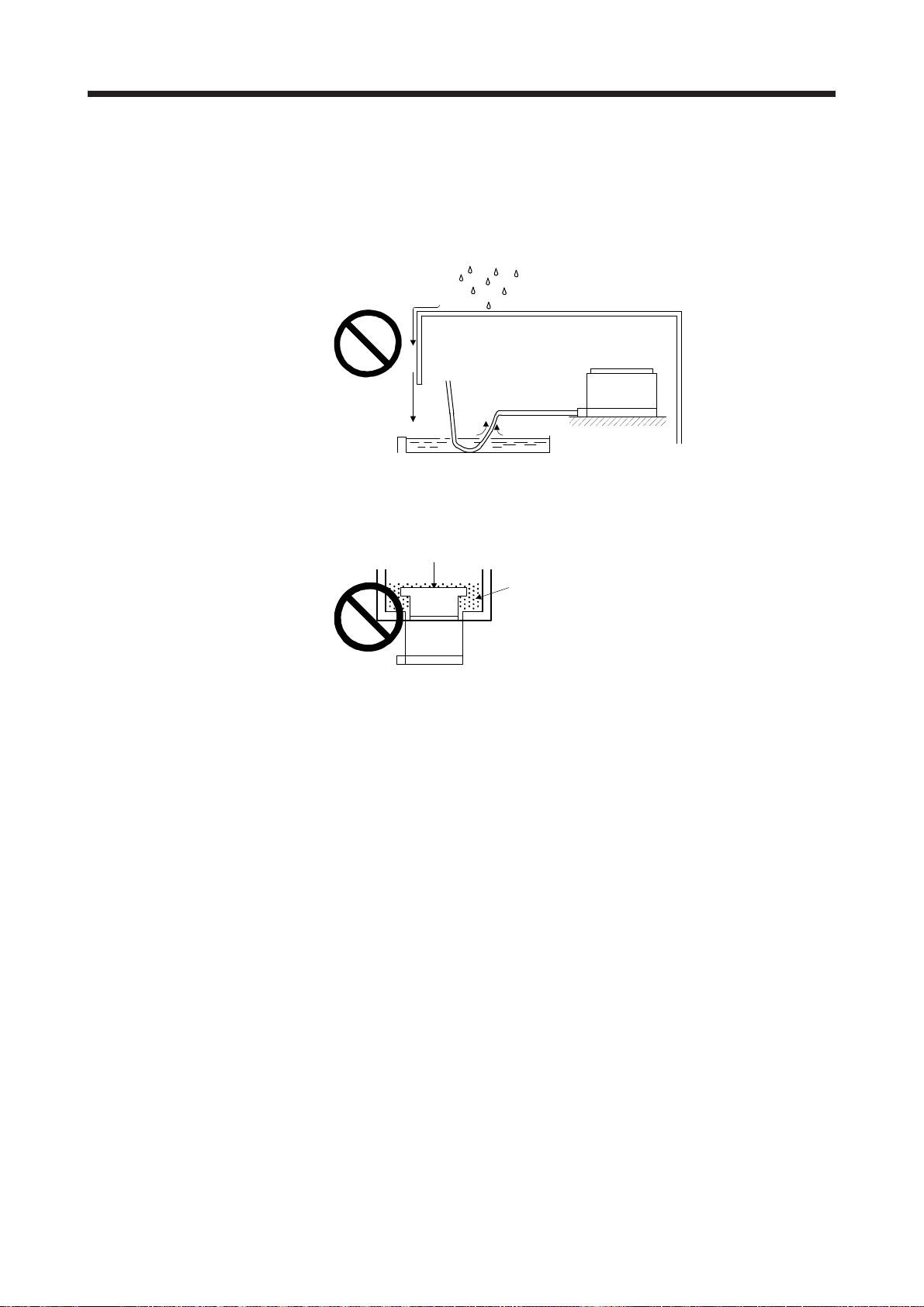
2.5 Protection from oil and water
Provide adequate protection to prevent foreign matter, such as oil and water, from entering the rotor of the
direct drive motor. When mounting the direct drive motor, consider the items in this section.
(1) Do not use the direct drive motor with its cable soaked in oil or water.
Cover
Oil/water pool
Capillary action
Direct drive motor
Provide measures so that the direct drive motor is not exposed to oil and water entering from the
machine side, rotating table, etc.
Lubricating oil
Rotary table, etc.
Direct drive motor
(3) If liquid such as coolant drops on the direct drive motor, the sealant, packing, cable and others may be
affected depending on the liquid type.
(4) In the environment where the direct drive motor is exposed to oil mist, steam, oil, water, grease, and/or
the like, a standard specification direct drive motor cannot be used. Provide measures to prevent dust
and/or water on the machine side.
2. INSTALLATION
2 - 5
2.6 Inspection items
WARNING
Before starting maintenance and/or inspection, turn off the power and wait for 15
minutes or more until the charge lamp turns off. Then, confirm that the voltage
between P+ and N- is safe with a voltage tester and others. Otherwise, an electric
shock may occur. In addition, when confirming whether the charge lamp is off or
not, always confirm it from the front of the servo amplifier.
To avoid an electric shock, only qualified personnel should attempt inspections.
For repair, contact your local sales office.
CAUTION
Do not perform insulation resistance test on the direct drive motor. Otherwise, it
may cause a malfunction.
Do not disassemble and/or repair the equipment on customer side.
It is recommended that the following points to be periodically checked.
(1) Check the bearings, etc. for unusual noise.
(2) Check the cables and the like for scratches or cracks. Especially when the junction cable is movable,
perform periodic inspection according to operating conditions.
(3) Check the power connector and encoder connector connections for looseness.
2.7 Parts having service life
Service life of the following parts is listed below. However, the service life varies depending on operation and
environment. If any fault is found in the parts, they must be replaced immediately regardless of their service
life. For parts replacement, contact your local sales office.
Part name Life guideline Remark
Bearings
20,000 hours to
30,000 hours
The Guideline of Life field gives the reference
time.
If any fault is found before this time is
reached, the part must be changed.
Encoder
20,000 hours to
30,000 hours
Absolute position
storage unit
(option)
20,000 hours to
30,000 hours
When the motor is run at rated speed under rated load, bearings should be exchanged in 20,000 to
30,000 hours as a guideline. This differs on the operating conditions. The bearings must also be changed if
unusual noise or vibration is found during inspection.
2. INSTALLATION
2 - 6
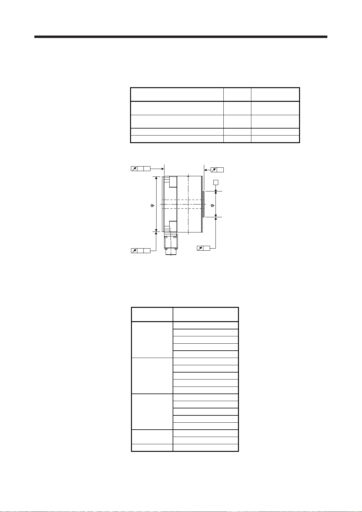
2.8 Machine accuracies
The following table indicates the machine accuracies of the rotor (output shaft) and the mounting area of the
direct drive motor (except special products).
Item
Measuring
position
Accuracy [mm]
Runout of mounting surface to rotor
(output shaft)
a 0.05
Runout of fitting outer diameter of
mounting surface
b 0.07
Runout of rotor (output shaft) c 0.04
Runout of rotor (output shaft) end d 0.02
Reference diagram
a
A
A
A
d
b
c
_
_
2.9 Flange size
The rated torque of the direct drive motor indicates the continuous permissible torque value that can be
generated when the motor is mounted on the aluminum flange specified in this table and used in the
environment of 0 °C to 40 °C ambient temperature.
Flange size
[mm]
Direct drive motor
TM-RG2M002C30
TM-RU2M002C30
400 × 400 × 20 TM-RFM002C20
TM-RFM004C20
TM-RFM006C20
TM-RG2M004E30
TM-RU2M004E30
550 × 550 × 35 TM-RFM006E20
TM-RFM012E20
TM-RFM018E20
TM-RG2M009G30
TM-RU2M009G30
650 × 650 × 35 TM-RFM012G20
TM-RFM048G20
TM-RFM072G20
750 × 750 × 45
TM-RFM040J10
TM-RFM120J10
950 × 950 × 50 TM-RFM240J10

2. INSTALLATION
2 - 7
2.10 Restrictions when using this product at altitudes exceeding 1000 m and up to 2000 m above sea level
As heat dissipation effects decrease in proportion to the decrease in air density, use the product within the
effective load ratio and regenerative load ratio shown in the following figure.
0
20001000
Altitude
95
100
0
Regenerative load ratio
Effective load ratio
[%]
[m]
2.11 Magnetic shielding
Do not place the direct drive motor near magnetic sources, such as a magnet. If it is unavoidable, block the
magnetic force by installing a shielding plate, etc.

2. INSTALLATION
2 - 8
MEMO
3. CONNECTORS USED FOR DIRECT DRIVE MOTOR WIRING
3 - 1
3. CONNECTORS USED FOR DIRECT DRIVE MOTOR WIRING
POINT
The IP rating indicated is the connector's protection against ingress of dust and
water when the connector is connected to a servo amplifier, direct drive motor,
or absolute position storage unit.
If the IP rating of the connector, servo amplifier, direct drive motor and absolute
position storage unit vary, the overall IP rating depends on the lowest IP rating of
all components.
3.1 Selection of connectors
Use the connector configuration products given in the table as the connectors for connection with the direct
drive motor. Refer to section 3.2 for the compatible connector configuration products.
Power supply connector Encoder connector
Absolute position
storage unit
MR-BTAS01
Servo amplifier
side connector
Encoder side
connector
Direct drive motor
Wiring connector
For power supply For encoder
Absolute position storage unit (option) (Note)
Servo amplifier side Encoder side
TM-RFM_C20
Connector
configuration B
Connector
configuration A
Connector
configuration A
Connector
configuration F
TM-RFM_E20
TM-RFM_G20
Connector
configuration C
TM-RFM040J10
Connector
configuration D
TM-RFM120J10
TM-RFM240J10
Connector
configuration E
TM-RG2M002C30
Connector
configuration B
TM-RU2M002C30
TM-RG2M004E30
TM-RU2M004E30
TM-RG2M009G30
TM-RU2M009G30
Note. Used in the absolute position detection system
3. CONNECTORS USED FOR DIRECT DRIVE MOTOR WIRING
3 - 2
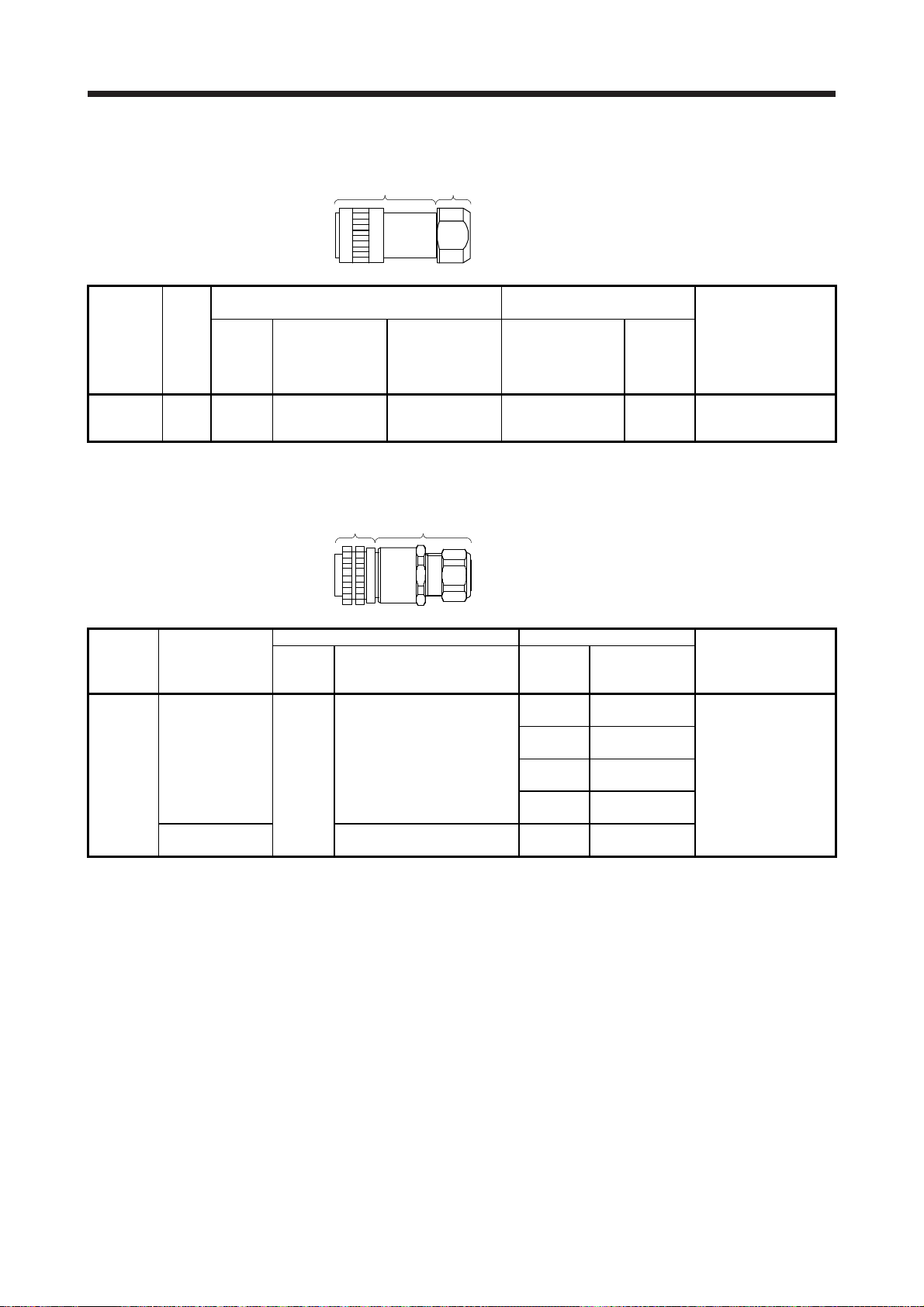
3.2 Wiring connectors (connector configurations A/B/C/D/E/F)
Cord
clamp
Plug
Connector
configuration
Feature
Plug (Hirose Electric)
Recommended cable
(Bando Densen)
Direct drive motor encoder
connector
or
Absolute position storage
unit connector
(servo amplifier side)
(Note 1)
Type Plug Cord clamp Model
Cable OD
[mm]
(reference)
A IP67 Straight RM15WTPZK-12S JR13WCCA-8(72)
20276
VSVPAWG#23×6P
KB-0492 (Note 2)
8.2 RM15WTRZB-12P(72)
Note 1. The connector to be mated.
2. Purchase from Toa Electric Industrial Co. Ltd., Nagoya Branch
Plug
Cable
clamp
Connector
configuration
Feature
Plug (DDK) Cable clamp
Direct drive motor power
connector (Note 2)
Type Model
Cable OD
[mm]
(reference)
Model
B
Straight
4 to 8
ACS-08RL-MS14F
(Nippon Flex)
CE05-2A14S-2PD-D
IP67
EN compliant
CE05-6A14S-2SD-D
Applicable wire size: AWG 22 to 16
8 to 12
ACS-12RL-MS14F
(Nippon Flex)
5 to 8.3
YSO14-5 to 8
(Daiwa Dengyo)
8.3 to 11.3
YSO14-9 to 11
(Daiwa Dengyo)
General environment
(Note 1)
D/MS3106B14S-2S
Applicable wire size: AWG 22 to 16
7.9 or less
(bushing ID)
D/MS3057-6A
Note 1. Not comply with EN.
2. The connector to be mated.
3. CONNECTORS USED FOR DIRECT DRIVE MOTOR WIRING
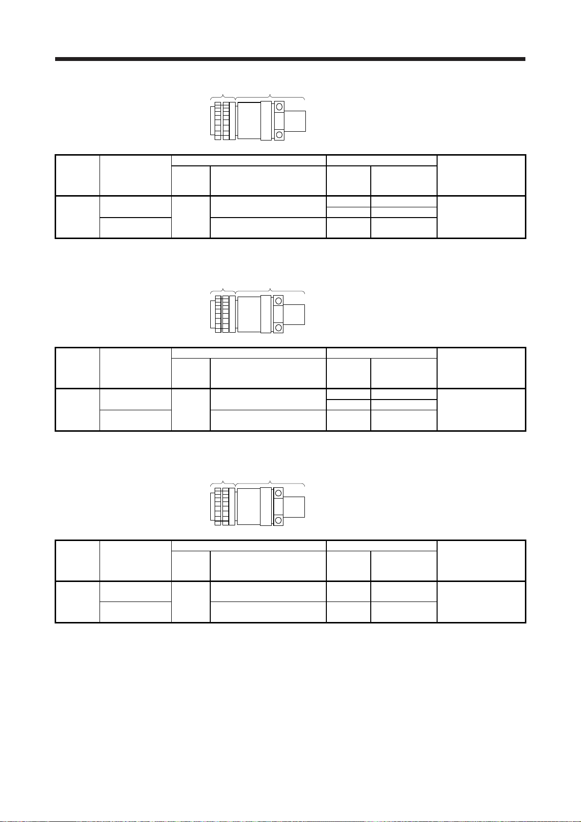
3 - 3
Cable clamp
Plug
Connector
configuration
Feature
Plug (DDK) Cable clamp (DDK)
Direct drive motor power
connector (Note 2)
Type Model
Cable OD
[mm]
(reference)
Model
C
IP67
EN compliant
Straight
CE05-6A18-10SD-D-BSS
Applicable wire size: AWG 14 to 12
8.5 to 11 CE3057-10A-2-D
CE05-2A18-10PD-D
10.5 to 14.1 CE3057-10A-1-D
General environment
(Note 1)
D/MS3106B18-10S
Applicable wire size: AWG 14 to 12
14.3 or less
(bushing ID)
D/MS3057-10A
Note 1. Not comply with EN.
2. The connector to be mated.
Cable clampPlug
Connector
configuration
Feature
Plug (DDK) Cable clamp (DDK)
Direct drive motor power
connector (Note 2)
Type Model
Cable OD
[mm]
(reference)
Model
D
IP67
EN compliant
Straight
CE05-6A22-22SD-D-BSS
Applicable wire size: AWG 10 to 8
9.5 to 13 CE3057-12A-2-D
CE05-2A22-22PD-D
12.5 to 16 CE3057-12A-1-D
General environment
(Note 1)
D/MS3106B22-22S
Applicable wire size: AWG 10 to 8
15.9 or less
(bushing ID)
D/MS3057-12A
Note 1. Not comply with EN.
2. The connector to be mated.
Cable clampPlug
Connector
configuration
Feature
Plug (DDK) Cable clamp (DDK)
Direct drive motor power
connector (Note 2)
Type Model
Cable OD
[mm]
(reference)
Model
E
IP67
EN compliant
Straight
CE05-6A32-17SD-D-BSS
Applicable wire size: AWG 6 to 4
22 to 23.8 CE3057-20A-1-D
CE05-2A32-17PD-D
General environment
(Note 1)
D/MS3106B32-17S
Applicable wire size: AWG 6 to 4
23.8 or less
(bushing ID)
D/MS3057-20A
Note 1. Not comply with EN.
2. The connector to be mated.

3. CONNECTORS USED FOR DIRECT DRIVE MOTOR WIRING
3 - 4
Cord
clamp
Plug
Connector
configuration
Feature
Plug (Hirose Electric) Recommended cable (Bando Densen)
Absolute position storage
unit connector
(encoder side) (Note 1)
Type Plug Cord clamp Model
Cable OD
[mm]
(reference)
F IP67 Straight RM15WTPZ-12P(72) JR13WCCA-8(72)
20276
VSVPAWG#23×6P
KB-0492 (Note 2)
8.2 RM15WTRZB-12S(72)
Note 1. The connector to be mated.
2. Purchase from Toa Electric Industrial Co. Ltd., Nagoya Branch
4. CONNECTOR DIMENSIONS
4 - 1
4. CONNECTOR DIMENSIONS
The following shows the dimensions of the connectors used for wiring the direct drive motor.
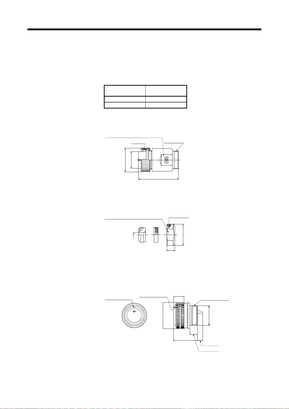
(1) Hirose Electric
(a) RM15WTPZK-12S/RM15WTPZ-12P(72)
Model
Connector
configuration (Note)
RM15WTPZK-12S A
RM15WTPZ-12P(72) F
Note. Refer to section 3.2 for the connector configuration.
[Unit: mm]
Spanner hook gap dimension: 18
M16 × 0.75
36.3
M19 × 1
φ21.5
φ15.2
(b) JR13WCCA-8(72)
Refer to the connector configurations A and F of section 3.2 for the connector configuration.
[Unit: mm]
8
φ20
7.5
M16 × 0.75
Spanner hook gap dimension: 17
(2) DDK
(a) CE05-6A14S-2SD-D
Refer to the connector configuration B of section 3.2 for the connector configuration.
[Unit: mm]
7/8-20UNEF-2B
(13.2)
24.0 ± 1
Positioning key
8.46 ± 0.5
5.6 ± 0.1
φ17.0 ± 0.25
φ28.57
3/4-20UNEF-2A
+ 0
- 0.38
Loading...