


Manual No.'10•SRK-T-100
TECHNICAL MANUAL
INVERTER WALL MOUNTED TYPE RESIDENTIAL AIR-CONDITIONERS (Split system, air to air heat pump type)
SRK25ZJP-S
SRK35ZJP-S
SRK50ZJP-S
Downloaded from AC-Manual.com Manuals
|
|
'10 • SRK-T-100 |
|
|
|
CONTENTS |
|
1. |
SPECIFICATIONS ........................................................................................ |
3 |
|
2. |
EXTERIOR DIMENSIONS ............................................................................ |
6 |
|
|
(1) |
Indoor units .......................................................................................... |
6 |
|
(2) |
Outdoor units ....................................................................................... |
7 |
|
(3) |
Wireless remote controller ................................................................... |
9 |
3. |
ELECTRICAL WIRING ................................................................................. |
10 |
|
|
(1) |
Indoor units .......................................................................................... |
10 |
|
(2) |
Outdoor units ....................................................................................... |
11 |
4. |
NOISE LEVEL ............................................................................................... |
13 |
|
5. |
PIPING SYSTEM ......................................................................................... |
16 |
|
6. |
RANGE OF USAGE & LIMITATIONS .......................................................... |
18 |
|
7. |
CAPACITY TABLES ................................................................................... |
20 |
|
8. |
APPLICATION DATA .................................................................................. |
21 |
|
9. |
OUTLINE OF OPERATION CONTROL BY MICROCOMPUTER ............... |
29 |
|
|
(1) |
Operation control function by remote controller .................................. |
29 |
|
(2) |
Unit ON/OFF button ........................................................................... |
30 |
|
(3) |
Auto restart function ......................................................................... |
30 |
|
(4) |
Custom cord switching procedure ....................................................... |
30 |
|
(5) |
Flap control ........................................................................................ |
31 |
|
(6) |
Timer operation .................................................................................. |
31 |
|
(7) |
Outline of heating operation ................................................................ |
32 |
|
(8) |
Outline of cooling operation ............................................................... |
33 |
|
(9) |
Outline of automatic operation ........................................................... |
33 |
|
(10) |
Protective control function ................................................................... |
34 |
10. |
MAINTENANCE DATA ............................................................................... |
38 |
|
|
(1) |
Cautions ............................................................................................. |
38 |
|
(2) |
Items to check before troubleshooting ................................................. |
38 |
|
(3) |
Troubleshooting procedure (If the air conditioner does not run at all) ........ |
38 |
|
(4) |
Troubleshooting procedure (If the air conditioner runs) ..................... |
39 |
|
(5) |
Self-diagnosis table ............................................................................. |
40 |
|
(6) |
Service mode (Trouble mode access function) ................................... |
41 |
|
(7) |
Inspection procedures corresponding to detail of trouble .................... |
49 |
- -
Downloaded from AC-Manual.com Manuals

|
|
'10 • SRK-T-100 |
(8) |
Phenomenon observed after shortcircuit, wire breakage on sensor |
......... 53 |
(9) |
Checking the indoor electrical equipment ........................................... |
53 |
(10) |
How to make sure of wireless remote controller .................................. |
54 |
(11) |
Outdoor unit inspection points .............................................................. |
55 |
■How to read the model name
Example: SRK 25 Z JP-S
Series code |
|
Inverter type |
|
Product capacit |
|
Model name SRK |
: Wall mounted type |
SRC |
: Outdoor unit |
- -
Downloaded from AC-Manual.com Manuals
|
|
|
|
|
|
|
|
|
|
|
|
|
|
|
|
|
|
|
|
|
|
'10 • SRK-T-100 |
|
1. SPECIFICATIONS |
|
|
|
|
|
|
|
|
|
|
|
Adapted to RoHS directive |
|
||||||||||
|
|
|
|
|
|
|
|
|
|
|
|
Model |
|
|
|
|
|
SRK25ZJP-S |
|
||||
Item |
|
|
|
|
|
|
|
|
|
|
|
Indoor unit SRK25ZJP-S |
|
Outdoor unit SRC25ZJP-S |
|
||||||||
Cooling capacity (1) |
|
|
|
|
|
|
|
|
|
W |
|
|
|
|
2500 (1000 (Min.)~2700 (Max.)) |
|
|||||||
Heating capacity (1) |
|
|
|
|
|
|
|
|
|
W |
|
|
|
|
3200 (1200 (Min.)~4200 (Max.)) |
|
|||||||
Power supply |
|
|
|
|
|
|
|
|
|
|
|
|
|
|
|
1 Phase, 220~240 V, 50Hz |
|||||||
|
|
|
Power |
|
|
|
|
Cooling |
|
kW |
|
|
|
|
0.71 (0.21~0.88) |
|
|
||||||
|
|
|
consumption |
|
Heating |
|
|
|
|
|
0.86 (0.27~1.46) |
|
|
||||||||||
|
|
|
|
|
|
|
|
|
|
|
|
|
|||||||||||
|
|
|
Running |
|
|
|
|
Cooling |
|
|
|
|
|
|
|
3.6 / 3.4 / 3.3 (220/ 230/ 240 V) |
|
||||||
|
|
|
current |
|
|
|
|
Heating |
|
A |
|
|
|
|
4.2 / 4.0 / 3.9 (220/ 230/ 240 V) |
|
|||||||
Operation |
|
Inrush current |
|
|
|
|
|
|
|
|
|
|
4.2 / 4.0 / 3.9 (220/ 230/ 240 V) |
||||||||||
|
|
|
|
|
|
|
Cooling |
|
|
|
|
|
|
|
3.52 |
|
|
||||||
data (1) |
|
COP |
|
|
|
|
|
|
|
|
|
|
|
|
|
||||||||
|
|
|
|
|
Heating |
|
|
|
|
|
|
|
3.72 |
|
|
||||||||
|
|
|
|
|
|
|
|
|
|
|
|
|
|
|
|
|
|
||||||
|
|
|
|
|
Cooling |
|
Sound level |
|
dB(A) |
|
Hi : 36 Me : 30 Lo : 22 |
|
46 |
|
|||||||||
|
|
|
Noise |
|
|
Power level |
|
dB |
|
52 |
|
|
|
|
56 |
|
|||||||
|
|
|
|
|
|
|
|
|
|
|
|
|
|
|
|||||||||
|
|
|
level |
|
Heating |
|
Sound level |
|
dB(A) |
|
Hi : 35 Me : 30 Lo : 26 |
|
48 |
|
|||||||||
|
|
|
|
|
|
|
|
|
Power level |
|
dB |
|
51 |
|
|
|
|
58 |
|
||||
Exterior dimensions (Height x Width x Depth) |
|
mm |
|
268 x 790 x 224 |
|
540 x 780 (+62) x 290 |
|||||||||||||||||
Exterior appearance |
|
|
|
|
|
|
|
|
|
|
|
|
|
Fine snow |
|
|
|
|
Stucco white |
||||
(Munsell color) |
|
|
|
|
|
|
|
|
|
|
|
(8.0Y 9.3/0.1) near equivalent |
|
(4.2Y 7.5/1.1) near equivalent |
|||||||||
Net weight |
|
|
|
|
|
|
|
|
|
kg |
|
8.5 |
|
|
|
|
32 |
|
|||||
|
|
|
|
|
|
|
|
|
|
|
|
|
|
|
|
|
|
|
|
||||
|
|
|
Compressor type & Q'ty |
|
|
|
|
|
— |
|
|
|
|
RM-B5077MDE1 (Rotary type) x 1 |
|
||||||||
|
|
|
Motor (Starting method) |
|
kW |
|
|
— |
|
|
|
|
0.75 (Line starting) |
|
|||||||||
Refrigerant |
|
Refrigerant oil |
|
|
|
|
|
|
|
|
|
|
0.35 (DIAMOND FREEZE MA68) |
|
|||||||||
|
Refrigerant (3) |
|
|
|
|
kg |
|
|
R410A 0.75 (Pre-Charged up to the piping length of 10m) |
|
|||||||||||||
equipment |
|
|
|
|
|
|
|
||||||||||||||||
|
Heat exchanger |
|
|
|
|
|
|
Louver fins & inner grooved tubing |
|
M fins & inner grooved tubing |
|||||||||||||
|
|
|
|
|
|
|
|
|
|
||||||||||||||
|
|
|
Refrigerant control |
|
|
|
|
|
Capillary tubes + Electronic expansion valve |
|
|||||||||||||
|
|
|
Deice control |
|
|
|
|
|
|
|
|
|
|
|
Microcomputer control |
|
|||||||
|
|
|
Fan type & Q'ty |
|
|
|
|
|
|
|
Tangential fan x 1 |
|
|
Propeller fan x 1 |
|||||||||
|
|
|
Motor |
|
|
|
|
|
|
|
W |
|
38 |
|
|
|
|
24 |
|
||||
Air handling |
|
Air flow |
|
|
|
|
Cooling |
|
CMM |
|
Hi : 8.0 Me : 6.2 Lo : 4.5 |
|
29.5 |
|
|||||||||
equipment |
|
|
|
|
|
Heating |
|
|
Hi : 9.3 Me : 7.8 Lo : 6.6 |
|
25.6 |
|
|||||||||||
|
|
|
|
|
|
|
|
|
|
|
|
|
|||||||||||
|
|
|
Fresh air intake |
|
|
|
|
|
|
|
|
Not possible |
|
|
— |
|
|||||||
|
|
|
Air filter, Quality / Quantity |
|
|
|
Polypropylene net (washable) x 2 |
|
|
— |
|
||||||||||||
Shock & vibration absorber |
|
|
|
|
|
|
|
|
|
|
|
— |
|
|
|
|
Cushion rubber (for compressor) |
|
|||||
|
|
|
Operation switch |
|
|
|
|
|
|
|
Wireless-Remote control |
|
|
— |
|
||||||||
Operation |
|
Room temperature control |
|
|
|
Microcomputer thermostat |
|
|
— |
|
|||||||||||||
control |
|
Operation Display |
|
|
|
|
|
|
|
|
RUN : Green, TIMER : Yellow, HI POWER : Green, |
||||||||||||
|
|
|
|
|
|
|
|
|
|
|
|
|
|
ECONO : Orange |
|
||||||||
|
|
|
|
|
|
|
|
|
|
|
|
|
|
|
|
|
|
|
|||||
|
|
|
|
|
|
|
|
|
|
|
|
|
|
|
|
Compressor overheat protection, Overcurrent protection, |
|||||||
Safety devices |
|
|
|
|
|
|
|
|
|
|
|
Frost protection, Serial signal error protection, Fan motor error protection, |
|||||||||||
|
|
|
|
|
|
|
|
|
|
|
|
|
|
Heating overload protection (High pressure control), Cooling overload protection |
|||||||||
|
|
|
Refrigerant piping size (O.D) |
|
mm |
|
|
Liquid line: φ6.35 (1/4") |
Gas line: φ9.52 (3/8") |
|
|||||||||||||
|
|
|
connecting method |
|
|
|
|
|
|
|
|
Flare connecting |
|
||||||||||
|
|
|
Attached length of piping |
|
m |
|
Liquid line : 0.4 |
|
|
— |
|||||||||||||
Installation |
|
|
|
|
Gas line : 0.33 |
|
|
||||||||||||||||
|
|
|
|
|
|
|
|
|
|
|
|
|
|
|
|
|
|
||||||
data |
|
Insulation for piping |
|
|
|
|
|
|
Necessary (Both sides), independent |
|
|||||||||||||
|
|
|
Refrigerant line (one way) length |
|
|
|
|
|
|
|
|
Max. 15 |
|
||||||||||
|
|
|
Vertical height difference between |
|
m |
|
|
|
|
Max.10 (Outdoor unit is higher) |
|||||||||||||
|
|
|
outdoor unit and indoor unit |
|
|
|
|
|
|
|
Max.10 (Outdoor unit is lower) |
|
|||||||||||
Drain hose |
|
|
|
|
|
|
|
|
|
|
|
|
Connectable (VP 16) |
|
|
— |
|
||||||
Power cable |
|
|
|
|
|
|
|
|
|
|
|
|
|
|
|
|
2m (3 Cores wih Earth) |
||||||
Recommended breaker size |
|
|
|
|
|
|
|
A |
|
|
|
|
16 |
|
|
|
|||||||
Connection wiring |
|
|
|
Size x Core number |
|
|
|
|
|
1.5mm2 x 4 cores (Including earth cable) |
|
||||||||||||
|
|
|
Connecting method |
|
|
|
|
|
|
Terminal block (Screw fixing type) |
|
||||||||||||
|
|
|
|
|
|
|
|
|
|
|
|
||||||||||||
Accessories (included) |
|
|
|
|
|
|
|
|
|
|
|
|
|
|
Mounting kit |
||||||||
Optional parts |
|
|
|
|
|
|
|
|
|
|
|
|
|
|
|
|
— |
|
|
|
|||
Note (1) The data are measured at the following conditions. |
|
|
|
|
|
The pipe length is 7.5m. |
|||||||||||||||||
|
|
|
|
|
|
|
|
|
|
|
|
|
|
|
|
|
|
||||||
|
|
|
|
|
Item |
|
Indoor air temperature |
|
Outdoor air temperature |
|
Standards |
|
|
||||||||||
|
|
|
|
|
|
|
|
|
|
|
|
|
|
|
|
|
|
|
|
||||
|
Operation |
|
|
|
|
DB |
|
WB |
|
DB |
|
WB |
|
|
|
|
|||||||
|
|
|
|
|
|
|
|
|
|
|
|
|
|
|
|||||||||
|
Cooling |
|
|
|
|
27˚C |
|
19˚C |
|
35˚C |
|
24˚C |
|
|
ISO-T1, JIS C 9612 |
|
|
||||||
|
|
|
|
|
|
|
|
|
|
|
|
|
|
|
|
|
|
|
|
||||
|
Heating |
|
|
|
|
20˚C |
|
— |
|
7˚C |
|
6˚C |
|
|
|
|
|||||||
|
|
|
|
|
|
|
|
|
|
|
|
|
|
|
|||||||||
|
|
|
|
|
|
|
|
|
|
|
|
|
|
|
|
|
|
|
|
|
|
|
|
(2)This air-conditioner is manufactured and tested in conformity with the ISO.
(3)The operation data are applied to the 220/230/240V districts respectively.
(4)The refrigerant quantity to be charged includes the refrigerant in 10m connecting piping. (Purging is not required even for the short piping.)
RWA000Z232
- -
Downloaded from AC-Manual.com Manuals

|
|
|
|
|
|
|
|
|
|
|
|
|
|
|
|
|
|
|
|
|
|
'10 • SRK-T-100 |
|
|
|
|
|
|
|
|
|
|
|
|
|
|
|
|
|
|
|
|
|
|
|
Adapted to RoHS directive |
|
|
|
|
|
|
|
|
|
|
|
|
|
|
|
|
|
|
|
|
|
|
|
|
|
|
|
|
|
|
|
|
|
|
|
|
|
Model |
|
|
|
|
|
SRK35ZJP-S |
|
||||
Item |
|
|
|
|
|
|
|
|
|
|
|
|
Indoor unit SRK35ZJP-S |
|
Outdoor unit SRC35ZJP-S |
|
|||||||
Cooling capacity (1) |
|
|
|
|
|
|
|
|
|
W |
|
|
|
|
3500 (1000 (Min.)~3700 (Max.)) |
|
|||||||
Heating capacity (1) |
|
|
|
|
|
|
|
|
|
W |
|
|
|
|
4000 (1300 (Min.)~4800 (Max.)) |
|
|||||||
Power supply |
|
|
|
|
|
|
|
|
|
|
|
|
|
|
|
|
1 Phase, 220~240 V, 50Hz |
||||||
|
|
|
Power |
|
|
|
|
Cooling |
|
kW |
|
|
|
|
1.06 (0.21~1.24) |
|
|
||||||
|
|
|
consumption |
|
Heating |
|
|
|
|
|
1.09 (0.29~1.58) |
|
|
||||||||||
|
|
|
|
|
|
|
|
|
|
|
|
|
|||||||||||
|
|
|
Running |
|
|
|
|
Cooling |
|
|
|
|
|
|
|
5.1 / 4.9 / 4.6 (220/ 230/ 240 V) |
|
||||||
|
|
|
current |
|
|
|
|
Heating |
|
A |
|
|
|
|
5.2 / 5.0 / 4.8 (220/ 230/ 240 V) |
|
|||||||
Operation |
|
Inrush current |
|
|
|
|
|
|
|
|
|
|
5.2 / 5.0 / 4.8 (220/ 230/ 240 V) |
||||||||||
|
|
|
|
|
|
|
Cooling |
|
|
|
|
|
|
|
3.30 |
|
|
||||||
data (1) |
|
COP |
|
|
|
|
|
|
|
|
|
|
|
|
|
||||||||
|
|
|
|
|
Heating |
|
|
|
|
|
|
|
3.67 |
|
|
||||||||
|
|
|
|
|
|
|
|
|
|
|
|
|
|
|
|
|
|
||||||
|
|
|
|
|
Cooling |
|
Sound level |
|
dB(A) |
|
Hi : 39 Me : 32 Lo : 23 |
|
49 |
|
|||||||||
|
|
|
Noise |
|
|
Power level |
|
dB |
|
54 |
|
|
|
|
59 |
|
|||||||
|
|
|
|
|
|
|
|
|
|
|
|
|
|
|
|||||||||
|
|
|
level |
|
Heating |
|
Sound level |
|
dB(A) |
|
Hi : 41 Me : 36 Lo : 27 |
|
51 |
|
|||||||||
|
|
|
|
|
|
|
|
|
Power level |
|
dB |
|
57 |
|
|
|
|
61 |
|
||||
Exterior dimensions (Height x Width x Depth) |
|
mm |
|
268 x 790 x 224 |
|
540 x 780 (+62) x 290 |
|||||||||||||||||
Exterior appearance |
|
|
|
|
|
|
|
|
|
|
|
|
|
Fine snow |
|
|
|
|
Stucco white |
||||
(Munsell color) |
|
|
|
|
|
|
|
|
|
|
|
(8.0Y 9.3/0.1) near equivalent |
|
(4.2Y 7.5/1.1) near equivalent |
|||||||||
Net weight |
|
|
|
|
|
|
|
|
|
kg |
|
8.5 |
|
|
|
|
35 |
|
|||||
|
|
|
Compressor type & Q'ty |
|
|
|
|
|
— |
|
|
|
|
RM-B5077MDE1 (Rotary type) x 1 |
|
||||||||
|
|
|
Motor (Starting method) |
|
kW |
|
|
— |
|
|
|
|
0.90 (Line starting) |
|
|||||||||
Refrigerant |
|
Refrigerant oil |
|
|
|
|
|
|
|
|
|
|
0.35 (DIAMOND FREEZE MA68) |
|
|||||||||
|
Refrigerant (3) |
|
|
|
|
kg |
|
|
R410A 1.05 (Pre-Charged up to the piping length of 15m) |
|
|||||||||||||
equipment |
|
|
|
|
|
|
|
||||||||||||||||
|
Heat exchanger |
|
|
|
|
|
|
Slit fins & inner grooved tubing |
|
M fins & inner grooved tubing |
|
||||||||||||
|
|
|
|
|
|
|
|
|
|
||||||||||||||
|
|
|
Refrigerant control |
|
|
|
|
|
Capillary tubes + Electronic expansion valve |
|
|||||||||||||
|
|
|
Deice control |
|
|
|
|
|
|
|
|
|
|
|
Microcomputer control |
|
|||||||
|
|
|
Fan type & Q'ty |
|
|
|
|
|
|
|
Tangential fan x 1 |
|
|
Propeller fan x 1 |
|||||||||
|
|
|
Motor |
|
|
|
|
|
|
|
W |
|
38 |
|
|
|
|
24 |
|
||||
Air handling |
|
Air flow |
|
|
|
|
Cooling |
|
CMM |
|
Hi : 8.5 Me : 6.8 Lo : 4.6 |
|
27.8 |
|
|||||||||
equipment |
|
|
|
|
|
Heating |
|
Hi : 11.0 Me : 8.4 Lo : 6.8 |
|
27.8 |
|
||||||||||||
|
|
|
|
|
|
|
|
|
|
|
|
||||||||||||
|
|
|
Fresh air intake |
|
|
|
|
|
|
|
|
Not possible |
|
|
— |
|
|||||||
|
|
|
Air filter, Quality / Quantity |
|
|
|
Polypropylene net (washable) x 2 |
|
|
— |
|
||||||||||||
Shock & vibration absorber |
|
|
|
|
|
|
|
|
|
|
|
— |
|
|
|
|
Cushion rubber (for compressor) |
|
|||||
|
|
|
Operation switch |
|
|
|
|
|
|
|
Wireless-Remote control |
|
|
— |
|||||||||
Operation |
|
Room temperature control |
|
|
|
Microcomputer thermostat |
|
|
— |
|
|||||||||||||
control |
|
Operation Display |
|
|
|
|
|
RUN : Green, TIMER : Yellow, HI POWER : Green, |
|||||||||||||||
|
|
|
|
|
|
|
|
|
|
|
ECONO : Orange |
|
|||||||||||
|
|
|
|
|
|
|
|
|
|
|
|
|
|
|
|
|
|
|
|||||
|
|
|
|
|
|
|
|
|
|
|
|
|
|
|
|
Compressor overheat protection, Overcurrent protection, |
|||||||
Safety devices |
|
|
|
|
|
|
|
|
|
|
|
Frost protection, Serial signal error protection, Fan motor error protection, |
|||||||||||
|
|
|
|
|
|
|
|
|
|
|
|
|
|
Heating overload protection (High pressure control), Cooling overload protection |
|||||||||
|
|
|
Refrigerant piping size (O.D) |
|
mm |
|
|
Liquid line :φ6.35 (1/4") |
Gas line :φ9.52 (3/8") |
|
|||||||||||||
|
|
|
connecting method |
|
|
|
|
|
|
|
|
Flare connecting |
|
||||||||||
|
|
|
Attached length of piping |
|
m |
|
Liquid line : 0.40 |
|
|
— |
|||||||||||||
Installation |
|
|
|
|
Gas line : 0.33 |
|
|
||||||||||||||||
|
|
|
|
|
|
|
|
|
|
|
|
|
|
|
|
|
|
||||||
data |
|
Insulation for piping |
|
|
|
|
|
|
Necessary (Both sides), independent |
|
|||||||||||||
|
|
|
Refrigerant line (one way) length |
|
|
|
|
|
|
|
|
Max. 15 |
|||||||||||
|
|
|
Vertical height difference between |
|
m |
|
|
|
|
Max.10 (Outdoor unit is higher) |
|||||||||||||
|
|
|
outdoor unit and indoor unit |
|
|
|
|
|
|
|
Max.10 (Outdoor unit is lower) |
|
|||||||||||
Drain hose |
|
|
|
|
|
|
|
|
|
|
|
|
Connectable (VP 16) |
|
|
— |
|
||||||
Power cable |
|
|
|
|
|
|
|
|
|
|
|
|
|
|
|
|
2m (3 Cores wih Earth) |
||||||
Recommended breaker size |
|
|
|
|
|
|
|
A |
|
|
|
|
16 |
|
|
|
|||||||
Connection wiring |
|
|
|
Size x Core number |
|
|
|
|
|
1.5mm2 x 4 cores (Including earth cable) |
|
||||||||||||
|
|
|
Connecting method |
|
|
|
|
|
|
Terminal block (Screw fixing type) |
|
||||||||||||
|
|
|
|
|
|
|
|
|
|
|
|
||||||||||||
Accessories (included) |
|
|
|
|
|
|
|
|
|
|
|
|
|
|
Mounting kit |
||||||||
Optional parts |
|
|
|
|
|
|
|
|
|
|
|
|
|
|
|
|
— |
|
|
|
|||
Note (1) The data are measured at the following conditions. |
|
|
|
|
|
The pipe length is 7.5m. |
|||||||||||||||||
|
|
|
|
|
|
|
|
|
|
|
|
|
|
|
|
|
|
||||||
|
|
|
|
|
Item |
|
Indoor air temperature |
|
Outdoor air temperature |
|
Standards |
|
|
||||||||||
|
|
|
|
|
|
|
|
|
|
|
|
|
|
|
|
|
|
|
|
||||
|
Operation |
|
|
|
|
DB |
|
WB |
|
DB |
|
WB |
|
|
|
|
|||||||
|
|
|
|
|
|
|
|
|
|
|
|
|
|
|
|||||||||
|
Cooling |
|
|
|
|
27˚C |
|
19˚C |
|
35˚C |
|
24˚C |
|
|
ISO-T1 , JIS C 9612 |
|
|
||||||
|
Heating |
|
|
|
|
20˚C |
|
— |
|
7˚C |
|
6˚C |
|
|
|
|
|||||||
|
|
|
|
|
|
|
|
|
|
|
|
|
|
|
|||||||||
|
|
|
|
|
|
|
|
|
|
|
|
|
|
|
|
|
|
|
|
|
|
|
|
(2)This air-conditioner is manufactured and tested in conformity with the ISO.
(3)The operation data are applied to the 220/230/240V districts respectively.
(4)The refrigerant quantity to be charged includes the refrigerant in 15m connecting piping. (Purging is not required even for the short piping.)
RWA000Z232
- -
Downloaded from AC-Manual.com Manuals
|
|
|
|
|
|
|
|
|
|
|
|
|
|
|
|
|
|
|
|
|
|
|
'10 • SRK-T-100 |
|
|
|
|
|
|
|
|
|
|
|
|
|
|
|
|
|
|
|
|
|
|
|
|
Adapted to RoHS directive |
|
|
|
|
|
|
|
|
|
|
|
|
|
|
|
|
|
|
|
|
|
|
|
|
|
|
|
|
|
|
|
|
|
|
|
|
|
|
|
Model |
|
|
|
|
|
SRK50ZJP-S |
|
||||
Item |
|
|
|
|
|
|
|
|
|
|
|
|
|
Indoor unit SRK50ZJP-S |
|
Outdoor unit SRC50ZJP-S |
|
|||||||
Cooling capacity (1) |
|
|
|
|
|
|
|
|
|
|
W |
|
|
|
|
5000 (1600 (Min.)~5500 (Max.)) |
|
|||||||
Heating capacity (1) |
|
|
|
|
|
|
|
|
|
|
W |
|
|
|
|
5800 (1600 (Min.)~6600 (Max.)) |
|
|||||||
Power supply |
|
|
|
|
|
|
|
|
|
|
|
|
|
|
|
|
|
1 Phase, 220~240 V, 50Hz |
||||||
|
|
|
Power |
|
|
|
|
Cooling |
|
|
kW |
|
|
|
|
1.56 (0.40~2.20) |
|
|
||||||
|
|
|
consumption |
|
Heating |
|
|
|
|
|
|
1.60 (0.42~2.10) |
|
|
||||||||||
|
|
|
|
|
|
|
|
|
|
|
|
|
|
|||||||||||
|
|
|
Running |
|
|
|
|
Cooling |
|
|
|
|
|
|
|
|
7.2 / 6.9 / 6.6 (220/ 230/ 240 V) |
|
||||||
|
|
|
current |
|
|
|
|
Heating |
|
|
A |
|
|
|
|
7.3 / 7.0 / 6.7 (220/ 230/ 240 V) |
|
|||||||
Operation |
|
Inrush current |
|
|
|
|
|
|
|
|
|
|
|
7.3 / 7.0 / 6.7 (220/ 230/ 240 V) |
||||||||||
|
|
|
|
|
|
|
Cooling |
|
|
|
|
|
|
|
|
3.21 |
|
|
||||||
data (1) |
|
COP |
|
|
|
|
|
|
|
|
|
|
|
|
|
|
||||||||
|
|
|
|
|
Heating |
|
|
|
|
|
|
|
|
3.63 |
|
|
||||||||
|
|
|
|
|
|
|
|
|
|
|
|
|
|
|
|
|
|
|
||||||
|
|
|
|
|
Cooling |
|
Sound level |
|
|
dB(A) |
|
Hi : 47 Me : 37 Lo : 26 |
|
51 |
|
|||||||||
|
|
|
Noise |
|
|
Power level |
|
|
dB |
|
63 |
|
|
|
|
61 |
|
|||||||
|
|
|
|
|
|
|
|
|
|
|
|
|
|
|
|
|||||||||
|
|
|
level |
|
Heating |
|
Sound level |
|
|
dB(A) |
|
Hi : 47 Me : 40 Lo : 33 |
|
53 |
|
|||||||||
|
|
|
|
|
|
|
|
|
Power level |
|
|
dB |
|
62 |
|
|
|
|
63 |
|
||||
Exterior dimensions (Height x Width x Depth) |
|
|
mm |
|
268 x 790 x 224 |
|
640 x 800 (+71) x 290 |
|||||||||||||||||
Exterior appearance |
|
|
|
|
|
|
|
|
|
|
|
|
|
|
Fine snow |
|
|
Stucco white |
||||||
(Munsell color) |
|
|
|
|
|
|
|
|
|
|
|
|
(8.0Y 9.3/0.1) near equivalent |
|
(4.2Y 7.5/1.1) near equivalent |
|||||||||
Net weight |
|
|
|
|
|
|
|
|
|
|
kg |
|
8.5 |
|
|
|
|
42 |
|
|||||
|
|
|
Compressor type & Q'ty |
|
|
|
|
|
|
— |
|
|
|
|
5RS132XAB21 (Rotary type) x 1 |
|
||||||||
|
|
|
Motor (Starting method) |
|
|
kW |
|
|
— |
|
|
|
|
1.50 (Line starting) |
|
|||||||||
Refrigerant |
|
Refrigerant oil |
|
|
|
|
|
|
|
|
|
|
|
|
0.37 (FV50S) |
|
||||||||
|
Refrigerant (3) |
|
|
|
|
|
kg |
|
|
R410A 1.35 (Pre-Charged up to the piping length of 15m) |
|
|||||||||||||
equipment |
|
|
|
|
|
|
|
|
||||||||||||||||
|
Heat exchanger |
|
|
|
|
|
|
|
Slit fins & inner grooved tubing |
|
M fins & inner grooved tubing |
|
||||||||||||
|
|
|
|
|
|
|
|
|
|
|
||||||||||||||
|
|
|
Refrigerant control |
|
|
|
|
|
|
Capillary tubes + Electronic expansion valve |
|
|||||||||||||
|
|
|
Deice control |
|
|
|
|
|
|
|
|
|
|
|
|
Microcomputer control |
|
|||||||
|
|
|
Fan type & Q'ty |
|
|
|
|
|
|
|
|
Tangential fan x 1 |
|
|
Propeller fan x 1 |
|||||||||
|
|
|
Motor |
|
|
|
|
|
|
|
|
W |
|
38 |
|
|
|
|
34 |
|
||||
Air handling |
|
Air flow |
|
|
|
|
Cooling |
|
|
CMM |
|
Hi : 11.0 Me : 7.6 Lo : 4.7 |
|
36.0 |
|
|||||||||
equipment |
|
|
|
|
|
Heating |
|
|
Hi : 13.8 Me : 10.7 Lo : 8.3 |
|
36.0 |
|
||||||||||||
|
|
|
|
|
|
|
|
|
|
|
|
|
||||||||||||
|
|
|
Fresh air intake |
|
|
|
|
|
|
|
|
|
Not possible |
|
|
— |
|
|||||||
|
|
|
Air filter, Quality / Quantity |
|
|
|
|
Polypropylene net (washable) x 2 |
|
|
— |
|
||||||||||||
Shock & vibration absorber |
|
|
|
|
|
|
|
|
|
|
|
|
— |
|
|
|
|
Cushion rubber (for compressor) |
|
|||||
|
|
|
Operation switch |
|
|
|
|
|
|
|
|
Wireless-Remote control |
|
|
— |
|||||||||
Operation |
|
Room temperature control |
|
|
|
|
Microcomputer thermostat |
|
|
— |
|
|||||||||||||
control |
|
Operation Display |
|
|
|
|
|
|
RUN : Green, TIMER : Yellow, HI POWER : Green, |
|||||||||||||||
|
|
|
|
|
|
|
|
|
|
|
|
ECONO : Orange |
|
|||||||||||
|
|
|
|
|
|
|
|
|
|
|
|
|
|
|
|
|
|
|
|
|||||
|
|
|
|
|
|
|
|
|
|
|
|
|
|
|
|
|
Compressor overheat protection, Overcurrent protection, |
|||||||
Safety devices |
|
|
|
|
|
|
|
|
|
|
|
|
Frost protection, Serial signal error protection, Fan motor error protection, |
|||||||||||
|
|
|
|
|
|
|
|
|
|
|
|
|
|
|
Heating overload protection (High pressure control), Cooling overload protection |
|||||||||
|
|
|
Refrigerant piping size (O.D) |
|
|
mm |
|
|
Liquid line :φ6.35 (1/4") |
Gas line :φ12.7 (1/2") |
|
|||||||||||||
|
|
|
connecting method |
|
|
|
|
|
|
|
|
|
Flare connecting |
|
||||||||||
|
|
|
Attached length of piping |
|
|
m |
|
|
Liquid line : 0.4 |
|
|
— |
||||||||||||
Installation |
|
|
|
|
|
Gas line : 0.33 |
|
|
||||||||||||||||
|
|
|
|
|
|
|
|
|
|
|
|
|
|
|
|
|
|
|
||||||
data |
|
Insulation for piping |
|
|
|
|
|
|
|
Necessary (Both sides), independent |
|
|||||||||||||
|
|
|
Refrigerant line (one way) length |
|
|
|
|
|
|
|
|
|
Max. 25 |
|||||||||||
|
|
|
Vertical height difference between |
|
m |
|
|
|
|
Max. 15 (Outdoor unit is higher) |
||||||||||||||
|
|
|
outdoor unit and indoor unit |
|
|
|
|
|
|
|
|
Max. 15 (Outdoor unit is lower) |
|
|||||||||||
Drain hose |
|
|
|
|
|
|
|
|
|
|
|
|
|
Connectable (VP 16) |
|
|
— |
|
||||||
Power cable |
|
|
|
|
|
|
|
|
|
|
|
|
|
|
|
|
|
2m (3 Cores wih Earth) |
||||||
Recommended breaker size |
|
|
|
|
|
|
|
|
A |
|
|
|
|
16 |
|
|
|
|||||||
Connection wiring |
|
|
|
Size x Core number |
|
|
|
|
|
|
1.5mm2 x 4 cores (Including earth cable) |
|
||||||||||||
|
|
|
Connecting method |
|
|
|
|
|
|
|
|
Terminal block (Screw fixing type) |
|
|||||||||||
|
|
|
|
|
|
|
|
|
|
|
|
|
|
|||||||||||
Accessories (included) |
|
|
|
|
|
|
|
|
|
|
|
|
|
|
|
Mounting kit |
||||||||
Optional parts |
|
|
|
|
|
|
|
|
|
|
|
|
|
|
|
|
|
— |
|
|
|
|||
Note (1) The data are measured at the following conditions. |
|
|
|
|
|
The pipe length is 7.5m. |
||||||||||||||||||
|
|
|
|
|
|
|
|
|
|
|
|
|
|
|
|
|
|
|||||||
|
|
|
|
|
Item |
|
Indoor air temperature |
|
Outdoor air temperature |
|
Standards |
|
|
|||||||||||
|
|
|
|
|
|
|
|
|
|
|
|
|
|
|
|
|
|
|
|
|
||||
|
Operation |
|
|
|
|
DB |
|
|
WB |
|
DB |
|
WB |
|
|
|
|
|||||||
|
|
|
|
|
|
|
|
|
|
|
|
|
|
|
|
|||||||||
|
Cooling |
|
|
|
|
27˚C |
|
19˚C |
|
35˚C |
|
24˚C |
|
|
ISO-T1 , JIS C 9612 |
|
|
|||||||
|
|
|
|
|
|
|
|
|
|
|
|
|
|
|
|
|
|
|
|
|
||||
|
Heating |
|
|
|
|
20˚C |
|
|
— |
|
7˚C |
|
6˚C |
|
|
|
|
|||||||
|
|
|
|
|
|
|
|
|
|
|
|
|
|
|
|
|||||||||
|
|
|
|
|
|
|
|
|
|
|
|
|
|
|
|
|
|
|
|
|
|
|
|
|
(2)This air-conditioner is manufactured and tested in conformity with the ISO.
(3)The operation data are applied to the 220/230/240V districts respectively.
(4)The refrigerant quantity to be charged includes the refrigerant in 15m connecting piping. (Purging is not required even for the short piping.)
RWA000Z232
- -
Downloaded from AC-Manual.com Manuals
- -
RKX000Z507
788
17.5 |
60 |
60 |
27 |
45
|
790 |
|
|
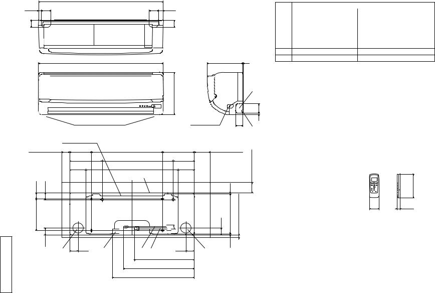
Outlet for down piping |
|
|
Refer to the above view |
|
Installation plate |
|
|
Service space 50 |
138 |
450 |
|
206.5 |
450 |
|
102.5 |
585 |
Unit
39.3 |
43.2 |
200 |
|
45
224 3
268 |
|
|
|
|
|
G |
|
|
|
|
|
|
|
|
|
|
|
|
|
60 |
|
Terminal block |
|
45 |
|
9 |
|
|
|
|
F |
|||
202 |
100 |
Service space |
|
|||
133.5 |
|
|
|
|
space |
|
|
|
|
|
|
|
|
102.5 |
|
|
|
|
Service |
|
|
|
|
|
|
|
|
|
|
|
7.5 |
|
65 |
|
|
|
44.5 |
252.2 |
Service space |
|
|
|
|
|
|
15 |
|
|
44.5 |
53.5 |
|
|
53.5 |
8.3 |
|
D |
E |
B A |
C |
|||
|
380.6 |
|||||
|
|
|
|
|
448.6
520
Space for installation and service when viewing from the front
Symbol |
Content |
|
|
|
|
|
|
A |
Gas piping |
Model 25,35 |
9.52 |
3 |
8" |
Flare |
|
Model 50 |
12.7 |
1 |
2" |
Flare |
|||
|
|
||||||
B |
Liquid piping |
6.35 1 4" |
Flare |
|
|
|
|
C |
Hole on wall for right rear piping |
65 |
|
|
|
|
|
D |
Hole on wall for left rear piping |
65 |
|
|
|
|
|
E |
Drain hose |
VP16 |
|
|
|
|
FOutlet for wiring
GOutlet for piping on both side
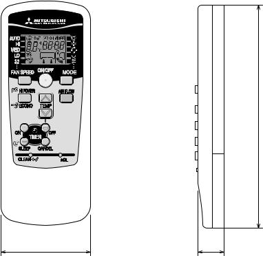
Wireless remote controller
|
|
150 |
|
60 |
17.3 |
Note 1 |
The model name label is attached |
|
|
on the underside of the panel. |
|
Unit:mm
DIMENSIONS EXTERIOR .2 units Indoor (1) S-50ZJP S,-35ZJP S,-SRK25ZJP Models
100-T-SRK • '10
Downloaded from AC-Manual.com Manuals
- -
A RCV000Z006
|
|
50.6 |
|
|
|
390.6 |
12 |
E |
|
63.4 |
|
D |
24.3 |
|
|
|
|
||
290 |
|
|
312.5 |
351.6 |
69.4 |
390.6 |
|
14.8 |
|
|
|
|
|
|
111.6 |
510 |
158.4 |
17.9 |
|
|
780 |
|
61.9 |
|
|
138.4 |
540 |
B |
|
42.5 |
|
97.7 |
|
15.8 |
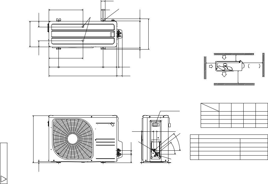
Notes
1 It must not be surrounded by walls on the four sides.
2The unit must be fixed with anchor bolts. An anchor bolt must not protrude more the 15mm.
3Where the unit is subject to strong winds, lay it in such a direction that the blower outlet faces perpendicularly to the dominant wind direction.
4Leave 1m or more space above the unit.
5A wall in front of the blower outlet must not exceed the units height.
6The model name label is attached on the lower right comer of the front panel.
L2 |
Intake |
L3 |
L4 |
|
|
Service space
Intake
Outlet L1
|
|
|
Minimum installation space |
|
|
|
|||
|
|
|
Examples of |
|
|
|
|
|
|
Terminal block |
|
|
installation |
|
|
|
|
|
|
|
|
Dimensions |
|
|
|
|
|
|
|
|
|
|
L1 |
Open |
280 |
280 |
|
180 |
|
|
|
|
L2 |
100 |
75 |
Open |
|
Open |
|
|
|
|
L3 |
100 |
80 |
80 |
|
80 |
|
|
|
|
L4 |
250 |
Open |
250 |
|
Open |
|
33.5 |
C |
|
|
|
|
|
|
|
|
|
|
|
|
|
|
|
|
|
|
|
|
Symbol |
|
Content |
|
|
|
|
|
|
40° |
A |
Service valve connection |
gas side |
|
9.52 |
3 |
8" |
Flare |
40° |
|
B |
Service valve connection |
liquid side |
|
6.35 |
1 |
4" |
Flare |
|
|
C |
Pipe cable draw-out hole |
|
|
|
|
|
|
|
|
D |
Drain discharge hole |
|
|
|
20 × 2places |
||
A |
|
E |
Anchor bolt hole |
|
|
M10 × 4places |
|||
|
|
|
|
|
|
|
|
|
|
Unit:mm
|
(2) |
SRC25ZJP Models |
units Outdoor |
S-35ZJP S,- |
|
100-T-SRK • '10
Downloaded from AC-Manual.com Manuals

Symbol |
Content |
|
|
A |
Service valve connection gas side |
φ12.7 1 2" Flare |
|
B |
Service valve connection liquid side |
φ6.35 1 4" Flare |
|
C |
Pipe cable draw-out hole |
|
|
D |
Drain discharge hole |
φ20 |
× 5places |
E |
Anchor bolt hole |
M10 |
× 4places |
|
|
520.6 |
161 |
|
|
|
|
327.3 |
50.6 |
|
|
|
38.6 |
D |
12 |
E |
|
43.5 |
35.6 |
|
|
24.3 |
|
90.6 |
|
|
|
|
|
290 |
|
|
|
312.5 |
351.6 |
- - |
83.5 |
327.3 |
|
14.8 |
|
|
89 |
510 |
201 |
17.9 |
|
|
|
800 |
|
71.2 |
|
Terminal block
|
640 |
|
RCT000Z005 |
12.4 |
93 42.5 |
148.4 |
33.5 |
C |
B |
|
40° |
|
|
|
|
|
40° |
|
A |
|
Downloaded from AC-Manual.com Manuals
2 The unit must be fixed with anchor bolts. An anchor bolt must not |
Model |
|
Notes |
|
|
1 It must not be surrounded by walls on the four sides. |
|
|
protrude more the 15mm. |
SRC50ZJP |
|
3 Where the unit is subject to strong winds, lay it in such |
||
|
||
a direction that the blower outlet faces perpendicularly |
|
|
to the dominant wind direction. |
|
|
4 Leave 1m or more space above the unit. |
|
|
5 A wall in front of the blower outlet must not exceed the units height. |
S- |
|
6 The model name label is attached on the right side of the unit. |
|
Intake |
L3 |
|
L2 |
L4 |
||
|
( Servicespace )
 Intake
|
Outlet |
L1 |
|
|
Minimum installation space |
|
|
||
Examples of |
|
|
|
|
installation |
|
|
|
|
|
||||
Dimensions
L1 |
Open |
280 |
280 |
180 |
L2 |
100 |
75 |
Open |
Open |
L3 |
100 |
80 |
80 |
80 |
L4 |
250 |
Open |
250 |
Open |
Unit:mm
100-T-SRK • '10
'10 • SRK-T-100
(3) Wireless remote controller
Unit: mm
150
60 |
17.3 |
- -
Downloaded from AC-Manual.com Manuals
0 - 1-
RWA000Z228
|
SM |
|
|
FM |
|
POWER SOURCE |
|
M |
|
|
M |
|
|
|
|
|
|
220 230 240V 50Hz |
||
|
5 |
|
|
|
CONTROL |
|
|
|
|
|
|
||
|
|
|
|
|
BOX |
|
|
|
|
RD BK WH Y BL |
|
HEAT |
|
|
|
|
|
EXCHANGERYG LB BR |
||
|
CNM |
|
1 3 4 5 6 |
|
||
|
|
|
|
CNU |
|
|
|
|
|
|
|
N WH |
|
|
U |
Va |
F |
|
|
|
|
|
|
52C-4 |
BR |
||
|
|
|
|
|
||
DS |
|
250V 3.15A |
|
|
||
|
|
|
|
|||
|
|
|
|
52C |
|
|
|
|
|
|
|
|
BK |
|
|
|
|
|
52C-3 |
|
|
PRINTED CIRCUIT |
J |
RD |
|||
|
|
|
||||
|
BOARD |
|
|
G |
Y G |
|
|
|
|
|
|
||
|
CNE |
|
CNG |
CNF |
BK WH RD Y G |
|
|
|
|
|
|
|
|
|
|
|
|
|
|
1 2 N 3 |
|
8 |
|
2 |
2 |
2 |
T |
|
|
t |
t |
|
|
|
DISPLAY |
|
|
|
|
|
|
WIRELESS |
|
ThI |
Th2 |
HD |
TO OUTDOOR UNIT |
|
R-AMP |
|
|
|
BACK UP SW |
|
|
SRK35, 50 MODELS ONLY |
|
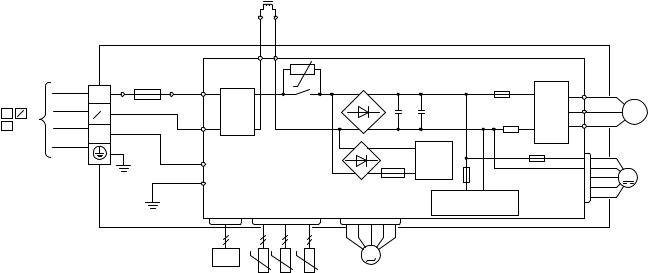
50ZJPS,-35ZJPS,-SRK25ZJPModels |
.3 |
Item |
WIRINGELECTRICAL units Indoor (1) |
|
Description |
|
|
CNE-CNU Connector |
|
|
FM |
Fan motor |
|
SM |
Flap motor |
|
HD |
Humidity sensor |
|
ThI |
Room temp. sensor |
|
Th2 |
Heat exch. sensor |
|
DS |
Diode stack |
|
F |
Fuse |
|
T |
Terminal block |
|
Va |
Varistor |
|
|
S- |
|
Mark |
Color |
|
BK |
Black |
|
BL |
Blue |
|
RD |
Red |
|
WH |
White |
|
Y |
Yellow |
|
Y G |
Yellow Green |
|
LB |
Light blue |
|
BR |
Brown |
|
100-T-SRK • '10
Downloaded from AC-Manual.com Manuals
|
|
|
|
|
|
|
|
|
|
L |
|
|
|
|
|
|
TERMINAL |
|
|
YOR |
|||
|
|
|
|
|
|
|
|
|
|||
|
|
|
|
|
BLOCK |
|
|
|
T1 T2 |
||
|
|
|
|
|
|
T |
|
|
250V 15A |
|
t |
|
|
|
|
|
|
|
|
|
|
||
|
|
TO INDOOR UNIT |
|
|
|
|
1 |
BK R.IN |
|
|
|
|
|
|
|
|
|
NOISE |
|||||
|
|
POWER WIRES |
1 |
2 N |
] |
|
2 |
|
|||
|
|
|
|
WH S.IN FILTER |
|||||||
|
|
[SIGNAL WIRE |
3 |
|
|
|
N |
||||
|
|
|
|
|
|
|
3 |
|
|
|
|
|
|
POWER SOURCE |
|
|
|
|
|
|
Y G RD C-2 |
|
|
|
|
220 230 240V 50Hz |
|
|
|
|
|
|
|||
|
|
|
|
|
|
|
|
|
Y G G1 |
|
|
11- |
|
|
|
|
|
|
|
|
CN20S |
CNTH |
|
|
|
|
|
|
|
|
|
|
t t t |
||
- |
|
|
|
|
|
|
|
|
20S |
||
|
|
|
|
|
|
|
|
|
|
TH1TH2 TH3 |
|
|
|
|
|
|
|
|
|
|
|
|
|
|
|
|
|
|
|
Item |
|
|
Description |
|
|
|
|
|
|
|
|
|
|
|
|
|
|
|
|
|
|
|
|
CM |
|
|
Compressor motor |
|
|
|
|
|
|
|
|
|
|
|
|
|
|
|
|
|
|
|
|
CN20S |
|
Connector |
|
|
|
|
|
|
|
|
|
CNTH |
|
|
|
|
|
|
|
|
|
|
|
CNEE |
|
|
|
|
|
|
|
|
|
|
|
|
|
|
|
|
|
|
|
|
|
|
|
EEV |
|
|
Electric expansion valve coil |
|
|
|
|
|
|
|
|
|
|
|
|
|
|
|
|
|
|
|
|
FMo |
|
|
Fan motor |
|
|
|
|
|
|
|
|
|
|
|
|
|
|
|
|
|
|
|
|
L |
|
|
Reactor |
|
|
|
|
|
|
|
|
|
|
|
|
|
|
|
|
|
|
|
|
T |
|
|
Terminal block |
|
|
|
|
|
|
|
|
|
|
|
|
|
|
|
|
|
|
|
|
TH1 |
|
|
Heat exchanger sensor outdoor unit |
|
|
|
|
|
|
|
|
|
|
|
|
|
|
|
|
|
|
|
|
TH2 |
|
|
Outdoor air temp.sensor |
|
|
|
RWC000Z236 |
|
|
|
|
TH3 |
|
|
Discharge pipe temp.sensor |
|
|
|
|
|
|
|
|
|
|
|
|
||
|
|
|
|
|
|
|
|
|
|
|
|
|
|
|
|
|
|
20S |
|
|
Solenoid valve for 4 way valve |
|
|
|
|
|
|
|
|
|
|
|
|
|
|
|
|
|
|
|
|
|
|
|
|
|
|
Downloaded from AC-Manual.com Manuals
|
|
|
|
PWB ASSY |
|
||
|
|
|
|
POWER |
|
|
|
|
|
|
|
TRANSISTOR |
|
||
+ |
+ |
|
F2 |
P |
U |
U RD |
|
|
|
|
|||||
|
250V 20A |
V |
V WH |
M |
|||
|
|
|
|
|
|||
|
|
|
|
|
W |
W BK |
3 |
|
|
|
|
N |
CM |
||
|
|
|
|
|
|
||
|
|
PAM |
|
F3 250V 1A |
|
|
|
F4 |
|
|
|
|
|
|
|
CIRCUIT |
F1 250V 2A |
|
|
|
M |
||
250V 10A |
|
|
CNFAN |
||||
|
|
SWITCHING POWER |
|
|
|
FMo |
|
CNEEV |
|
|
CIRCUIT |
|
|
|
|
M
EEV
Mark |
Color |
|
|
BK |
Black |
|
|
OR |
Orange |
|
|
RD |
Red |
|
|
WH |
White |
|
|
Y |
Yellow |
|
|
Y G |
Yellow Green |
|
|
|
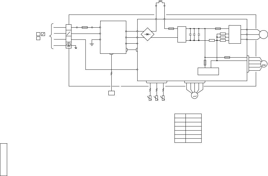
(2) |
SRC25ZJP Models |
units Outdoor |
S-35ZJP S,- |
|
100-T-SRK • '10
|
|
TERMINAL |
|
|
|
BLOCK T |
1 |
TO INDOOR UNIT |
|
|
|
POWER WIRES |
1 2 N |
] |
2 |
N |
|||
[SIGNAL WIRE |
3 |
3 |
|
POWER SOURCE220 230 240V 50Hz
- 12-
RWC000Z237
Downloaded from AC-Manual.com Manuals
L
|
PWB ASSY SUB |
||
FUSE |
BK RIN |
|
|
|
|
|
|
250V 20A |
WH SIN |
RO |
BK R |
|
|
|
|
|
|
SO |
WH S |
|
Y G G1 |
S-1 |
WH S-2 |
Y G |
|
|
BK CNSUB |
|
|
CNMAIN |
|
CN20S
RD
RD C-2
20S
Item |
Description |
|
|
CM |
Compressor motor |
|
|
CN20S |
|
CNTH |
Connector |
CNEE |
|
EEV |
Electric expansion valve coil |
|
|
FMo |
Fan motor |
|
|
L |
Reactor |
|
|
T |
Terminal block |
|
|
TH1 |
Heat exchanger sensor outdoor unit |
|
|
TH2 |
Outdoor air temp.sensor |
|
|
TH3 |
Discharge pipe temp.sensor |
|
|
20S |
Solenoid valve for 4 way valve |
|
|
|
Y |
OR |
|
|
|
|
|
|
|
|
PWB ASSY MAIN |
|
|
|
|
||
|
T1 |
T2 |
|
|
POWER |
|
|
|
|
|
F8 |
|
F2 |
TRANSISTOR |
|
|
|
|
|
|
P |
|
U |
RD |
||
|
|
|
|
|
U |
|||
|
|
250V 20A ACTIVE |
|
250V 20A |
|
|
||
|
|
+ + + |
V V |
WH |
||||
|
|
FILTER |
|
NU |
||||
|
|
UNIT |
|
|
NV |
W |
W |
BK |
|
|
|
|
|
NW |
|||
|
|
|
|
|
|
|
||
|
|
|
|
|
F3 250V 1A |
|
|
|
|
|
|
F1 |
250V 2A |
|
CNFAN |
|
|
|
|
|
|
|
|
|
||
|
|
|
SWITCHING POWER |
|
|
|
|
|
|
|
|
CIRCUIT |
|
|
|
|
|
|
CNTH |
|
CNEEV |
|
|
|
|
|
t |
t |
t |
M |
|
|
|
|
|
TH1 |
TH2 |
TH3 |
EEV |
|
|
|
|
|
|
|
|
|
|
|
|||
|
|
Mark |
Color |
|
|
|
|
|
|
|
BK |
Black |
|
|
|
|
|
|
|
OR |
Orange |
|
|
|
|
|
|
|
RD |
Red |
|
|
|
|
|
|
|
WH |
White |
|
|
|
|
|
|
|
Y |
Yellow |
|
|
|
|
|
|
|
Y G |
Yellow Green |
|
|
|
|
|
M
3
CM
M
FMo
S-SRC50ZJP Model
100-T-SRK • '10
'10 • SRK-T-100
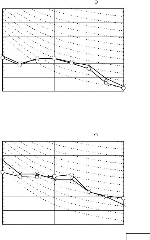
4. NOISE LEVEL
Model SRK25ZJP-S |
|
|
|
|
|
|
|||
|
|
|
|
|
|
|
|
||
(Indoor Unit) |
|
|
|
Condition |
ISO-T1,JIS C9612 |
|
|||
|
|
|
|
|
|
|
|
||
|
|
|
|
|
|
|
|
||
|
|
|
|
|
|
|
|
|
|
Model |
|
SRK25ZJP-S |
|
|
|
|
|
|
|
Noise |
Cooling |
|
36 dB(A) |
|
|
|
|
|
|
Level |
Heating |
|
35 dB(A) |
|
× ...... Cooling, |
|
Heating |
||
|
|
|
|
|
|
||||
Sound Pressure Level (dB) (standard 2×10⁻⁵ Pa)
70 |
|
|
|
|
|
|
70 |
|
|
|
|
|
|
|
N70 |
60 |
|
|
|
|
|
|
60 |
|
|
|
|
|
|
|
N60 |
50 |
|
|
|
|
|
|
50 |
|
|
|
|
|
|
|
N50 |
40 |
|
|
|
|
|
|
40 |
|
|
|
|
|
|
|
N40 |
30 |
|
|
|
|
|
|
30 |
|
|
|
|
|
|
|
N30 |
20 |
|
|
|
|
|
|
20 |
|
|
|
|
|
|
|
N20 |
10 |
|
|
|
|
|
|
10 |
63 |
125 |
250 |
500 |
1000 |
2000 |
4000 |
8000 |
|
|
Mid Octave Band frequency (Hz) |
|
|
|
||
(Outdoor Unit) |
|
|
|
|
|
|
|
|
|
|
|
|
|
Model |
|
SRC25ZJP-S |
|
|
|
|
Noise |
Cooling |
|
46 dB(A) |
|
|
|
Level |
Heating |
|
48 dB(A) |
× ...... Cooling, |
|
Heating |
|
|
|
|
|
||
Sound Pressure Level (dB) (standard 2×10⁻⁵ Pa)
70 |
|
|
|
|
|
|
70 |
|
|
|
|
|
|
|
N70 |
60 |
|
|
|
|
|
|
60 |
|
|
|
|
|
|
|
N60 |
50 |
|
|
|
|
|
|
50 |
|
|
|
|
|
|
|
N50 |
40 |
|
|
|
|
|
|
40 |
|
|
|
|
|
|
|
N40 |
30 |
|
|
|
|
|
|
30 |
|
|
|
|
|
|
|
N30 |
20 |
|
|
|
|
|
|
20 |
|
|
|
|
|
|
|
N20 |
10 |
|
|
|
|
|
|
10 |
63 |
125 |
250 |
500 |
1000 |
2000 |
4000 |
8000 |
|
|
Mid Octave Band frequency (Hz) |
|
|
ISC09164 |
||
|
|
|
|
|
|
|
|
- 13 -
Downloaded from AC-Manual.com Manuals

'10 • SRK-T-100
Model SRK35ZJP-S |
|
|
|
|
|
|
|||
|
|
|
|
|
|
|
|
||
(Indoor Unit) |
|
|
|
Condition |
ISO-T1,JIS C9612 |
|
|||
|
|
|
|
|
|
|
|
||
|
|
|
|
|
|
|
|
||
Model |
|
SRK35ZJP-S |
|
|
|
|
|
|
|
Noise |
Cooling |
|
39 dB(A) |
|
|
|
|
|
|
Level |
Heating |
|
41 dB(A) |
|
× ...... Cooling, |
|
Heating |
||
|
|
|
|
|
|
||||
Sound Pressure Level (dB) (standard 2×10⁻⁵ Pa)
70 |
|
|
|
|
|
|
70 |
|
|
|
|
|
|
|
N70 |
60 |
|
|
|
|
|
|
60 |
|
|
|
|
|
|
|
N60 |
50 |
|
|
|
|
|
|
50 |
|
|
|
|
|
|
|
N50 |
40 |
|
|
|
|
|
|
40 |
|
|
|
|
|
|
|
N40 |
30 |
|
|
|
|
|
|
30 |
|
|
|
|
|
|
|
N30 |
20 |
|
|
|
|
|
|
20 |
|
|
|
|
|
|
|
N20 |
10 |
|
|
|
|
|
|
10 |
63 |
125 |
250 |
500 |
1000 |
2000 |
4000 |
8000 |
|
|
Mid Octave Band frequency (Hz) |
|
|
|
||
(Outdoor Unit) |
|
|
|
|
|
|
Model |
|
SRC35ZJP-S |
|
|
|
|
Noise |
Cooling |
|
49 dB(A) |
|
|
|
Level |
Heating |
|
51 dB(A) |
× ...... Cooling, |
|
Heating |
|
|
|
|
|
||
Sound Pressure Level (dB) (standard 2×10⁻⁵ Pa)
70 |
|
|
|
|
|
|
70 |
|
|
|
|
|
|
|
N70 |
60 |
|
|
|
|
|
|
60 |
|
|
|
|
|
|
|
N60 |
50 |
|
|
|
|
|
|
50 |
|
|
|
|
|
|
|
N50 |
40 |
|
|
|
|
|
|
40 |
|
|
|
|
|
|
|
N40 |
30 |
|
|
|
|
|
|
30 |
|
|
|
|
|
|
|
N30 |
20 |
|
|
|
|
|
|
20 |
|
|
|
|
|
|
|
N20 |
10 |
|
|
|
|
|
|
10 |
63 |
125 |
250 |
500 |
1000 |
2000 |
4000 |
8000 |
|
|
Mid Octave Band frequency (Hz) |
|
|
|
||
ISC09164
- 14 -
Downloaded from AC-Manual.com Manuals

'10 • SRK-T-100
Model SRK50ZJP-S |
|
|
|
|
|
|
|||
|
|
|
|
|
|
|
|
||
(Indoor Unit) |
|
|
|
Condition |
ISO-T1,JIS C9612 |
|
|||
|
|
|
|
|
|
|
|
||
|
|
|
|
|
|
|
|
||
Model |
|
SRK50ZJP-S |
|
|
|
|
|
|
|
Noise |
Cooling |
|
47 dB(A) |
|
|
|
|
|
|
Level |
Heating |
|
47 dB(A) |
|
× ...... Cooling, |
|
Heating |
||
|
|
|
|
|
|
||||
Sound Pressure Level (dB) (standard 2×10⁻⁵ Pa)
70 |
|
|
|
|
|
|
70 |
|
|
|
|
|
|
|
N70 |
60 |
|
|
|
|
|
|
60 |
|
|
|
|
|
|
|
N60 |
50 |
|
|
|
|
|
|
50 |
|
|
|
|
|
|
|
N50 |
40 |
|
|
|
|
|
|
40 |
|
|
|
|
|
|
|
N40 |
30 |
|
|
|
|
|
|
30 |
|
|
|
|
|
|
|
N30 |
20 |
|
|
|
|
|
|
20 |
|
|
|
|
|
|
|
N20 |
10 |
|
|
|
|
|
|
10 |
63 |
125 |
250 |
500 |
1000 |
2000 |
4000 |
8000 |
|
|
Mid Octave Band frequency (Hz) |
|
|
|
||
(Outdoor Unit) |
|
|
|
|
|
|
Model |
|
SRC50ZJP-S |
|
|
|
|
Noise |
Cooling |
|
51 dB(A) |
|
|
|
Level |
Heating |
|
53 dB(A) |
× ...... Cooling, |
|
Heating |
|
|
|
|
|
||
Sound Pressure Level (dB) (standard 2×10⁻⁵ Pa)
70 |
|
|
|
|
|
|
70 |
|
|
|
|
|
|
|
N70 |
60 |
|
|
|
|
|
|
60 |
|
|
|
|
|
|
|
N60 |
50 |
|
|
|
|
|
|
50 |
|
|
|
|
|
|
|
N50 |
40 |
|
|
|
|
|
|
40 |
|
|
|
|
|
|
|
N40 |
30 |
|
|
|
|
|
|
30 |
|
|
|
|
|
|
|
N30 |
20 |
|
|
|
|
|
|
20 |
|
|
|
|
|
|
|
N20 |
10 |
|
|
|
|
|
|
10 |
63 |
125 |
250 |
500 |
1000 |
2000 |
4000 |
8000 |
|
|
Mid Octave Band frequency (Hz) |
|
|
|
||
ISC09164
- 15 -
Downloaded from AC-Manual.com Manuals

'10 • SRK-T-100
55.PIPINGSYSTEM
ModelsSRK20ZJSRK25ZJP-S,-S25ZJ-S
ModelSRK35ZJP-S -S
Humidity sensor
(HD)
- 16 -
Downloaded from AC-Manual.com Manuals

Model SRK50ZJP-S
Indoor unit |
Flare |
|
Outdoor unit |
|
connection |
Service valve |
|
|
|
|
|
|
|
|
(Gas) |
|
Heat |
Gas pipie |
Check joint |
Room temp. |
(φ12.7) |
||
sensor |
exchanger |
|
|
sensor |
|
|
|
(Th1) |
|
|
|
(Th2) |
|
|
|
|
|
|
4way valve |
Humidity |
|
|
|
sensor |
|
|
|
(HD) |
Heat |
|
|
|
|
|
|
|
exchanger |
|
|
Liquid |
Service valve |
|
pipe |
(Liquid) |
|
(φ6.35) |
||
|
||
Flare connection |
Strainer |
|
|
Discharge pipe temp. sensor
(TH3)
Muffler
Compressor
Receiver
Electronic expansion valve
(EEV) Capillary tube
- 17 -
'10 • SRK-T-100
Cooling cycle
Heating cycle
Outdoor air temp. sensor
(TH2)
Muffler
Heat exchanger
Heat exchanger sensor
(TH1)
Capillary tube
Muffler
Downloaded from AC-Manual.com Manuals
 Loading...