


 Loading...
FR Configurator2
INSTRUCTION MANUAL
INVERTER SETUP SOFTWARE
SW1DND-FRC2-E

INTRODUCTION . . . . . . . . . . . . . . . . . . . . . . . . . . . . . . . . . . . . . . . . . . . . . . . . . . . . . . . . . . . . . . . . . 4
Chapter 1 OUTLINE. . . . . . . . . . . . . . . . . . . . . . . . . . . . . . . . . . . . . 6
1.1 Before using this software . . . . . . . . . . . . . . . . . . . . . . . . . . . . . . . . . . . . . . . . . . . . . . . . . . . . . 7
1.1.1 Product confirmation . . . . . . . . . . . . . . . . . . . . . . . . . . . . . . . . . . . . . . . . . . . . . . . . . . . . . . . . . . . . . . . . . . . . . . . . . . . . . . 10
1.2 System configuration . . . . . . . . . . . . . . . . . . . . . . . . . . . . . . . . . . . . . . . . . . . . . . . . . . . . . . . . 11
1.2.1 System requirement for FR Configurator2 . . . . . . . . . . . . . . . . . . . . . . . . . . . . . . . . . . . . . . . . . . . . . . . . . . . . . . . . . . . . . 11 1.2.2 Compatible inverters . . . . . . . . . . . . . . . . . . . . . . . . . . . . . . . . . . . . . . . . . . . . . . . . . . . . . . . . . . . . . . . . . . . . . . . . . . . . . . 12 1.2.3 System configuration. . . . . . . . . . . . . . . . . . . . . . . . . . . . . . . . . . . . . . . . . . . . . . . . . . . . . . . . . . . . . . . . . . . . . . . . . . . . . . 14
1.3 Installation and uninstallation. . . . . . . . . . . . . . . . . . . . . . . . . . . . . . . . . . . . . . . . . . . . . . . . . . 19
1.3.1 Installation of FR Configurator2 . . . . . . . . . . . . . . . . . . . . . . . . . . . . . . . . . . . . . . . . . . . . . . . . . . . . . . . . . . . . . . . . . . . . . 19
1.3.2 Uninstallation of FR Configurator2 . . . . . . . . . . . . . . . . . . . . . . . . . . . . . . . . . . . . . . . . . . . . . . . . . . . . . . . . . . . . . . . . . . . 21
1.4 Connection and parameter setting. . . . . . . . . . . . . . . . . . . . . . . . . . . . . . . . . . . . . . . . . . . . . . 23
1.4.1 Connection method . . . . . . . . . . . . . . . . . . . . . . . . . . . . . . . . . . . . . . . . . . . . . . . . . . . . . . . . . . . . . . . . . . . . . . . . . . . . . . . 23 1.4.2 Connection using USB connector . . . . . . . . . . . . . . . . . . . . . . . . . . . . . . . . . . . . . . . . . . . . . . . . . . . . . . . . . . . . . . . . . . . . 26 1.4.3 Connection using PU connector . . . . . . . . . . . . . . . . . . . . . . . . . . . . . . . . . . . . . . . . . . . . . . . . . . . . . . . . . . . . . . . . . . . . . 30 1.4.4 Connection of inverter via Ethernet. . . . . . . . . . . . . . . . . . . . . . . . . . . . . . . . . . . . . . . . . . . . . . . . . . . . . . . . . . . . . . . . . . . 35 1.4.5 Connection of multiple inverters using RS-485 terminal . . . . . . . . . . . . . . . . . . . . . . . . . . . . . . . . . . . . . . . . . . . . . . . . . . . 41 1.4.6 Connection through GOT (FA transparent function) . . . . . . . . . . . . . . . . . . . . . . . . . . . . . . . . . . . . . . . . . . . . . . . . . . . . . . 43 1.4.7 Connection with programmable controller. . . . . . . . . . . . . . . . . . . . . . . . . . . . . . . . . . . . . . . . . . . . . . . . . . . . . . . . . . . . . . 50 1.4.8 Connection via a GOT2000 model and a programmable controller . . . . . . . . . . . . . . . . . . . . . . . . . . . . . . . . . . . . . . . . . . 50 1.4.9 Connection using CC-Link IE TSN . . . . . . . . . . . . . . . . . . . . . . . . . . . . . . . . . . . . . . . . . . . . . . . . . . . . . . . . . . . . . . . . . . . 51
1.5 Setting of operation mode of the inverter. . . . . . . . . . . . . . . . . . . . . . . . . . . . . . . . . . . . . . . . . 53
1.6 Start and close of FR Configurator2 . . . . . . . . . . . . . . . . . . . . . . . . . . . . . . . . . . . . . . . . . . . . 57
1.6.1 Starting FR Configurator2 . . . . . . . . . . . . . . . . . . . . . . . . . . . . . . . . . . . . . . . . . . . . . . . . . . . . . . . . . . . . . . . . . . . . . . . . . . 57
1.6.2 Closing FR Configurator2 . . . . . . . . . . . . . . . . . . . . . . . . . . . . . . . . . . . . . . . . . . . . . . . . . . . . . . . . . . . . . . . . . . . . . . . . . . 57
Chapter 2 PROJECT CREATION . . . . . . . . . . . . . . . . . . . . . . . . . 60
2.1 Project file operation . . . . . . . . . . . . . . . . . . . . . . . . . . . . . . . . . . . . . . . . . . . . . . . . . . . . . . . . 60
2.1.1 Procedure to create a project . . . . . . . . . . . . . . . . . . . . . . . . . . . . . . . . . . . . . . . . . . . . . . . . . . . . . . . . . . . . . . . . . . . . . . . 60 2.1.2 Creating a new project file. . . . . . . . . . . . . . . . . . . . . . . . . . . . . . . . . . . . . . . . . . . . . . . . . . . . . . . . . . . . . . . . . . . . . . . . . . 60 2.1.3 Connection setting . . . . . . . . . . . . . . . . . . . . . . . . . . . . . . . . . . . . . . . . . . . . . . . . . . . . . . . . . . . . . . . . . . . . . . . . . . . . . . . 63
2.2 Explanation of the operating window of FR Configurator2 . . . . . . . . . . . . . . . . . . . . . . . . . . . 69
2.2.1 Main frame . . . . . . . . . . . . . . . . . . . . . . . . . . . . . . . . . . . . . . . . . . . . . . . . . . . . . . . . . . . . . . . . . . . . . . . . . . . . . . . . . . . . . 69 2.2.2 Project tree area . . . . . . . . . . . . . . . . . . . . . . . . . . . . . . . . . . . . . . . . . . . . . . . . . . . . . . . . . . . . . . . . . . . . . . . . . . . . . . . . . 69 2.2.3 Pop-up menu. . . . . . . . . . . . . . . . . . . . . . . . . . . . . . . . . . . . . . . . . . . . . . . . . . . . . . . . . . . . . . . . . . . . . . . . . . . . . . . . . . . . 71 2.2.4 Sub-window area . . . . . . . . . . . . . . . . . . . . . . . . . . . . . . . . . . . . . . . . . . . . . . . . . . . . . . . . . . . . . . . . . . . . . . . . . . . . . . . . 71 2.2.5 Menu bar and toolbar . . . . . . . . . . . . . . . . . . . . . . . . . . . . . . . . . . . . . . . . . . . . . . . . . . . . . . . . . . . . . . . . . . . . . . . . . . . . . 72 2.2.6 Status bar . . . . . . . . . . . . . . . . . . . . . . . . . . . . . . . . . . . . . . . . . . . . . . . . . . . . . . . . . . . . . . . . . . . . . . . . . . . . . . . . . . . . . . 78
2.3 File operation and print . . . . . . . . . . . . . . . . . . . . . . . . . . . . . . . . . . . . . . . . . . . . . . . . . . . . . . 79
2.3.1 List of file types . . . . . . . . . . . . . . . . . . . . . . . . . . . . . . . . . . . . . . . . . . . . . . . . . . . . . . . . . . . . . . . . . . . . . . . . . . . . . . . . . . 79 2.3.2 Open the file . . . . . . . . . . . . . . . . . . . . . . . . . . . . . . . . . . . . . . . . . . . . . . . . . . . . . . . . . . . . . . . . . . . . . . . . . . . . . . . . . . . . 79 2.3.3 Save the file . . . . . . . . . . . . . . . . . . . . . . . . . . . . . . . . . . . . . . . . . . . . . . . . . . . . . . . . . . . . . . . . . . . . . . . . . . . . . . . . . . . . 80 2.3.4 Import the data . . . . . . . . . . . . . . . . . . . . . . . . . . . . . . . . . . . . . . . . . . . . . . . . . . . . . . . . . . . . . . . . . . . . . . . . . . . . . . . . . . 80 2.3.5 Print. . . . . . . . . . . . . . . . . . . . . . . . . . . . . . . . . . . . . . . . . . . . . . . . . . . . . . . . . . . . . . . . . . . . . . . . . . . . . . . . . . . . . . . . . . . 80
CONTENTS
1

2.3.6 Print preview . . . . . . . . . . . . . . . . . . . . . . . . . . . . . . . . . . . . . . . . . . . . . . . . . . . . . . . . . . . . . . . . . . . . . . . . . . . . . . . . . . . . 81
2.4 Display setting . . . . . . . . . . . . . . . . . . . . . . . . . . . . . . . . . . . . . . . . . . . . . . . . . . . . . . . . . . . . .82
2.4.1 Switch the display language . . . . . . . . . . . . . . . . . . . . . . . . . . . . . . . . . . . . . . . . . . . . . . . . . . . . . . . . . . . . . . . . . . . . . . . . 82
Chapter 3 FUNCTION . . . . . . . . . . . . . . . . . . . . . . . . . . . . . . . . . . 84
3.1 Parameter list . . . . . . . . . . . . . . . . . . . . . . . . . . . . . . . . . . . . . . . . . . . . . . . . . . . . . . . . . . . . . .84
3.1.1 Parameter list . . . . . . . . . . . . . . . . . . . . . . . . . . . . . . . . . . . . . . . . . . . . . . . . . . . . . . . . . . . . . . . . . . . . . . . . . . . . . . . . . . . 85 3.1.2 Parameter clear / all parameter clear . . . . . . . . . . . . . . . . . . . . . . . . . . . . . . . . . . . . . . . . . . . . . . . . . . . . . . . . . . . . . . . . . 86 3.1.3 Parameter read (batch read) and write (batch write) . . . . . . . . . . . . . . . . . . . . . . . . . . . . . . . . . . . . . . . . . . . . . . . . . . . . . 86 3.1.4 Parameter verification . . . . . . . . . . . . . . . . . . . . . . . . . . . . . . . . . . . . . . . . . . . . . . . . . . . . . . . . . . . . . . . . . . . . . . . . . . . . . 87 3.1.5 Editing the individual list . . . . . . . . . . . . . . . . . . . . . . . . . . . . . . . . . . . . . . . . . . . . . . . . . . . . . . . . . . . . . . . . . . . . . . . . . . . 88 3.1.6 Settings by function. . . . . . . . . . . . . . . . . . . . . . . . . . . . . . . . . . . . . . . . . . . . . . . . . . . . . . . . . . . . . . . . . . . . . . . . . . . . . . . 88
3.2 Convert. . . . . . . . . . . . . . . . . . . . . . . . . . . . . . . . . . . . . . . . . . . . . . . . . . . . . . . . . . . . . . . . . . .97
3.2.1 Schematic illustration of the convert function . . . . . . . . . . . . . . . . . . . . . . . . . . . . . . . . . . . . . . . . . . . . . . . . . . . . . . . . . . . 97 3.2.2 Convert window. . . . . . . . . . . . . . . . . . . . . . . . . . . . . . . . . . . . . . . . . . . . . . . . . . . . . . . . . . . . . . . . . . . . . . . . . . . . . . . . . . 98 3.2.3 Connection setting for the convert function. . . . . . . . . . . . . . . . . . . . . . . . . . . . . . . . . . . . . . . . . . . . . . . . . . . . . . . . . . . . . 99 3.2.4 Convert procedures. . . . . . . . . . . . . . . . . . . . . . . . . . . . . . . . . . . . . . . . . . . . . . . . . . . . . . . . . . . . . . . . . . . . . . . . . . . . . . . 99 3.2.5 Precautions for the convert function . . . . . . . . . . . . . . . . . . . . . . . . . . . . . . . . . . . . . . . . . . . . . . . . . . . . . . . . . . . . . . . . . 102
3.3 Graph . . . . . . . . . . . . . . . . . . . . . . . . . . . . . . . . . . . . . . . . . . . . . . . . . . . . . . . . . . . . . . . . . . .110
3.3.1 Graph window . . . . . . . . . . . . . . . . . . . . . . . . . . . . . . . . . . . . . . . . . . . . . . . . . . . . . . . . . . . . . . . . . . . . . . . . . . . . . . . . . . 111 3.3.2 Graph window toolbar . . . . . . . . . . . . . . . . . . . . . . . . . . . . . . . . . . . . . . . . . . . . . . . . . . . . . . . . . . . . . . . . . . . . . . . . . . . . 111 3.3.3 Sampling settings . . . . . . . . . . . . . . . . . . . . . . . . . . . . . . . . . . . . . . . . . . . . . . . . . . . . . . . . . . . . . . . . . . . . . . . . . . . . . . . 112 3.3.4 Trigger settings . . . . . . . . . . . . . . . . . . . . . . . . . . . . . . . . . . . . . . . . . . . . . . . . . . . . . . . . . . . . . . . . . . . . . . . . . . . . . . . . . 116 3.3.5 Changing scale and the graph display . . . . . . . . . . . . . . . . . . . . . . . . . . . . . . . . . . . . . . . . . . . . . . . . . . . . . . . . . . . . . . . 118 3.3.6 Cursor function . . . . . . . . . . . . . . . . . . . . . . . . . . . . . . . . . . . . . . . . . . . . . . . . . . . . . . . . . . . . . . . . . . . . . . . . . . . . . . . . . 120 3.3.7 Displaying history . . . . . . . . . . . . . . . . . . . . . . . . . . . . . . . . . . . . . . . . . . . . . . . . . . . . . . . . . . . . . . . . . . . . . . . . . . . . . . . 120 3.3.8 Graph measurement procedure example (monitoring output frequency, terminal RUN, and terminal FU) . . . . . . . . . . . 121
3.4 Batch monitor . . . . . . . . . . . . . . . . . . . . . . . . . . . . . . . . . . . . . . . . . . . . . . . . . . . . . . . . . . . . .126
3.5 I/O terminal monitor . . . . . . . . . . . . . . . . . . . . . . . . . . . . . . . . . . . . . . . . . . . . . . . . . . . . . . . .129
3.6 Diagnostics. . . . . . . . . . . . . . . . . . . . . . . . . . . . . . . . . . . . . . . . . . . . . . . . . . . . . . . . . . . . . . .130
3.6.1 Faults history function . . . . . . . . . . . . . . . . . . . . . . . . . . . . . . . . . . . . . . . . . . . . . . . . . . . . . . . . . . . . . . . . . . . . . . . . . . . . 130 3.6.2 Serial number function . . . . . . . . . . . . . . . . . . . . . . . . . . . . . . . . . . . . . . . . . . . . . . . . . . . . . . . . . . . . . . . . . . . . . . . . . . . 130 3.6.3 Life check . . . . . . . . . . . . . . . . . . . . . . . . . . . . . . . . . . . . . . . . . . . . . . . . . . . . . . . . . . . . . . . . . . . . . . . . . . . . . . . . . . . . . 131 3.6.4 Diagnosis result output . . . . . . . . . . . . . . . . . . . . . . . . . . . . . . . . . . . . . . . . . . . . . . . . . . . . . . . . . . . . . . . . . . . . . . . . . . . 132 3.6.5 Ethernet status . . . . . . . . . . . . . . . . . . . . . . . . . . . . . . . . . . . . . . . . . . . . . . . . . . . . . . . . . . . . . . . . . . . . . . . . . . . . . . . . . 132 3.6.6 Online status . . . . . . . . . . . . . . . . . . . . . . . . . . . . . . . . . . . . . . . . . . . . . . . . . . . . . . . . . . . . . . . . . . . . . . . . . . . . . . . . . . . 133
3.7 Test Operation . . . . . . . . . . . . . . . . . . . . . . . . . . . . . . . . . . . . . . . . . . . . . . . . . . . . . . . . . . . .134
3.7.1 Test operation window . . . . . . . . . . . . . . . . . . . . . . . . . . . . . . . . . . . . . . . . . . . . . . . . . . . . . . . . . . . . . . . . . . . . . . . . . . . 134 3.7.2 Displaying and switching the operation mode. . . . . . . . . . . . . . . . . . . . . . . . . . . . . . . . . . . . . . . . . . . . . . . . . . . . . . . . . . 134 3.7.3 Specifying the running frequency (rotation speed, machine speed) . . . . . . . . . . . . . . . . . . . . . . . . . . . . . . . . . . . . . . . . . 135 3.7.4 Running the inverter in test operation (forward rotation, reverse rotation, and stop commands) . . . . . . . . . . . . . . . . . . . 136
3.8 Using the PLC function. . . . . . . . . . . . . . . . . . . . . . . . . . . . . . . . . . . . . . . . . . . . . . . . . . . . . .137
3.8.1 Before using Developer. . . . . . . . . . . . . . . . . . . . . . . . . . . . . . . . . . . . . . . . . . . . . . . . . . . . . . . . . . . . . . . . . . . . . . . . . . . 137 3.8.2 Starting the Developer function. . . . . . . . . . . . . . . . . . . . . . . . . . . . . . . . . . . . . . . . . . . . . . . . . . . . . . . . . . . . . . . . . . . . . 138 3.8.3 Basic menu . . . . . . . . . . . . . . . . . . . . . . . . . . . . . . . . . . . . . . . . . . . . . . . . . . . . . . . . . . . . . . . . . . . . . . . . . . . . . . . . . . . . 139 3.8.4 Ladder edit menu . . . . . . . . . . . . . . . . . . . . . . . . . . . . . . . . . . . . . . . . . . . . . . . . . . . . . . . . . . . . . . . . . . . . . . . . . . . . . . . 142 3.8.5 Structured ladder edit menu . . . . . . . . . . . . . . . . . . . . . . . . . . . . . . . . . . . . . . . . . . . . . . . . . . . . . . . . . . . . . . . . . . . . . . . 145 3.8.6 Label edit menu. . . . . . . . . . . . . . . . . . . . . . . . . . . . . . . . . . . . . . . . . . . . . . . . . . . . . . . . . . . . . . . . . . . . . . . . . . . . . . . . . 147
2

3.8.7 Device comment edit menu. . . . . . . . . . . . . . . . . . . . . . . . . . . . . . . . . . . . . . . . . . . . . . . . . . . . . . . . . . . . . . . . . . . . . . . . 147 3.8.8 Verification result menu. . . . . . . . . . . . . . . . . . . . . . . . . . . . . . . . . . . . . . . . . . . . . . . . . . . . . . . . . . . . . . . . . . . . . . . . . . . 147
3.9 USB memory parameter copy file edit function . . . . . . . . . . . . . . . . . . . . . . . . . . . . . . . . . . . 149
3.9.1 USB parameter copy file editor menu and toolbar . . . . . . . . . . . . . . . . . . . . . . . . . . . . . . . . . . . . . . . . . . . . . . . . . . . . . . 149 3.9.2 Editing parameter setting values. . . . . . . . . . . . . . . . . . . . . . . . . . . . . . . . . . . . . . . . . . . . . . . . . . . . . . . . . . . . . . . . . . . . 150 3.9.3 Verifying parameters . . . . . . . . . . . . . . . . . . . . . . . . . . . . . . . . . . . . . . . . . . . . . . . . . . . . . . . . . . . . . . . . . . . . . . . . . . . . . 150
3.10 Ethernet parameter setting function. . . . . . . . . . . . . . . . . . . . . . . . . . . . . . . . . . . . . . . . . . . . 152
3.10.1 Ethernet parameter setting . . . . . . . . . . . . . . . . . . . . . . . . . . . . . . . . . . . . . . . . . . . . . . . . . . . . . . . . . . . . . . . . . . . . . . . . 152 3.10.2 Batch assignment dialog . . . . . . . . . . . . . . . . . . . . . . . . . . . . . . . . . . . . . . . . . . . . . . . . . . . . . . . . . . . . . . . . . . . . . . . . . . 153 3.10.3 Writing result . . . . . . . . . . . . . . . . . . . . . . . . . . . . . . . . . . . . . . . . . . . . . . . . . . . . . . . . . . . . . . . . . . . . . . . . . . . . . . . . . . . 154 3.10.4 Procedure for connecting inverters via Ethernet . . . . . . . . . . . . . . . . . . . . . . . . . . . . . . . . . . . . . . . . . . . . . . . . . . . . . . . . 155
3.11 iQSS backup file conversion function . . . . . . . . . . . . . . . . . . . . . . . . . . . . . . . . . . . . . . . . . . 157
3.11.1 iQSS backup file conversion . . . . . . . . . . . . . . . . . . . . . . . . . . . . . . . . . . . . . . . . . . . . . . . . . . . . . . . . . . . . . . . . . . . . . . . 157
3.12 Help . . . . . . . . . . . . . . . . . . . . . . . . . . . . . . . . . . . . . . . . . . . . . . . . . . . . . . . . . . . . . . . . . . . . 158
3.12.1 [FR Configurator2 help] menu. . . . . . . . . . . . . . . . . . . . . . . . . . . . . . . . . . . . . . . . . . . . . . . . . . . . . . . . . . . . . . . . . . . . . . 158 3.12.2 [Instruction Manual of the inverter] menu . . . . . . . . . . . . . . . . . . . . . . . . . . . . . . . . . . . . . . . . . . . . . . . . . . . . . . . . . . . . . 158 3.12.3 Connection to Mitsubishi Electric FA Global Website . . . . . . . . . . . . . . . . . . . . . . . . . . . . . . . . . . . . . . . . . . . . . . . . . . . . 160 3.12.4 Version information . . . . . . . . . . . . . . . . . . . . . . . . . . . . . . . . . . . . . . . . . . . . . . . . . . . . . . . . . . . . . . . . . . . . . . . . . . . . . . 160
Chapter 4 TROUBLE INDICATION . . . . . . . . . . . . . . . . . . . . . . . 164
4.1 Error code . . . . . . . . . . . . . . . . . . . . . . . . . . . . . . . . . . . . . . . . . . . . . . . . . . . . . . . . . . . . . . . 164
4.1.1 Communication error with the inverter . . . . . . . . . . . . . . . . . . . . . . . . . . . . . . . . . . . . . . . . . . . . . . . . . . . . . . . . . . . . . . . 164 4.1.2 Communication error with the GOT . . . . . . . . . . . . . . . . . . . . . . . . . . . . . . . . . . . . . . . . . . . . . . . . . . . . . . . . . . . . . . . . . 171
CONTENTS
3

INTRODUCTION
Thank you for choosing this Mitsubishi Electric Inverter Setup Software.
This Instruction Manual provides handling information and precautions for use of this product. Incorrect handling might cause an unexpected fault. Before using the software, please read this Instruction Manual carefully to use the software to its optimum performance.
Please forward this Instruction Manual to the end user.
When reading this Instruction Manual, note the following.
•This Instruction Manual is written on the basis that Windows® 7 Professional (32-bit) (English version) is the operating system.
To use this software on the 64-bit system, read "\Program Files" used in this Instruction Manual as "\Program Files (x86)".
•Drive D is described as the DVD drive and Drive C as the hard disk drive.
Trademarks
•Microsoft, Windows, Windows Vista, Internet Explorer, and Excel are registered trademarks or trademarks of Microsoft Corporation in the United States and other countries.
The formal name of Windows® XP is Microsoft® Windows® XP operating system. The formal name of Windows Vista® is Microsoft® Windows Vista® operating system. The formal name of Windows® 7 is Microsoft® Windows® 7 operating system.
The formal name of Windows® 8 is Microsoft® Windows® 8 operating system. The formal name of Windows® 10 is Microsoft® Windows® 10 operating system.
•Intel, Celeron, and Pentium are registered trademarks or trademark of Intel Corporation in the United States and/or other countries.
•Ethernet is a registered trademark of Fuji Xerox Corporation.
•MODBUS is a registered trademark of SCHNEIDER ELECTRIC USA, INC.
•FR Configurator2 is a registered trademark of Mitsubishi Electric Corporation.
The copyright and other rights of this software all belong to Mitsubishi Electric Corporation.
•No part of this Instruction Manual may be copied or reproduced without the permission of Mitsubishi Electric Corporation.
•Other company and product names herein are the trademarks and registered trademarks of their respective owners.
•SPREAD
Copyright (C) 2003-2004, FarPoint Technologies, Inc. All rights reserved.
•TeeChart
Copyright (C) 1997-2005 by David Berneda, Steema Software
•Xtreme Toolkit
Copyright (C) 1998-2009 Codejock Software, a division of Codejock Technologies, LLC
•CodeProject
A slider with 2 buttons by includeh10, an Australia member of www.codeproject.com, licensed under CPOL
For Maximum Safety
This product has not been designed or manufactured for the use with any equipment or system operated under lifethreatening conditions.
Please contact our sales office when you are considering using this product in special applications such as passenger mobile, medical, aerospace, nuclear, power or undersea relay equipment or system.
Although this product was manufactured under conditions of strict quality control, you are strongly advised to install safety devices to prevent serious accidents when it is used in facilities where breakdowns of the product are likely to cause a serious accident.
4

CHAPTER 1 OUTLINE
CHAPTER 1
1.1 |
Before using this software ........................................................................................................................................ |
7 |
1.2 |
System configuration .............................................................................................................................................. |
11 |
1.3 |
Installation and uninstallation.................................................................................................................................. |
19 |
1.4 |
Connection and parameter setting.......................................................................................................................... |
23 |
1.5 |
Setting of operation mode of the inverter................................................................................................................ |
53 |
1.6 |
Start and close of FR Configurator2 ....................................................................................................................... |
57 |
5

1 OUTLINE
This chapter explains the outline for use of this product. Always read the instructions before using the software.
The available connection methods and usable parameters differ depending on the inverter. For the details, refer to the Instruction Manual of the inverter.
Abbreviation / generic name
Item |
Description |
|
Operation panel |
Operation panel (FR-DU08) and LCD operation panel (FR-LU08) |
|
Parameter unit |
Parameter unit (FR-PU07) |
|
PU |
Operation panel and parameter unit |
|
Inverter |
Mitsubishi Electric inverter / sensorless servo |
|
FR-A800 |
Mitsubishi Electric FR-A800 series / FR-A800 Plus series inverter |
|
FR-B |
Mitsubishi Electric FR-B inverter (A800 specifications) |
|
FR-B3 |
Mitsubishi Electric FR-B3 inverter (A800 specifications) |
|
FR-F800 |
Mitsubishi Electric FR-F800 series inverter |
|
FR-CS80 |
Mitsubishi Electric FREQROL-CS80 inverter |
|
FR-A700 |
Mitsubishi Electric FR-A700 series inverter |
|
FR-B (700) |
Mitsubishi Electric FR-B inverter (A700 specifications) |
|
FR-B3 (700) |
Mitsubishi Electric FR-B3 inverter (A700 specifications) |
|
FR-D700 |
Mitsubishi Electric FR-D700 series inverter |
|
FR-F700 |
Mitsubishi Electric FR-F700 series inverter |
|
FR-F700P |
Mitsubishi Electric FR-F700P series inverter |
|
FR-E700 |
Mitsubishi Electric FR-E700 series inverter |
|
FR-E700EX |
Mitsubishi Electric FR-E700EX series sensorless servo drive unit |
|
FR-E700-NE |
Mitsubishi Electric FR-E700 inverter Ethernet model |
|
FR-E560 |
Mitsubishi Electric FR-E500 series inverter |
|
Pr. |
Parameter number (Number assigned to function) |
|
PU operation |
The start and frequency commands are given by the operation panel, parameter unit, or RS-485 |
|
communication, via the PU connector. |
||
|
||
NET operation |
The start and frequency commands are given via the RS-485 terminals, a communication option, or the |
|
Ethernet connector. |
||
|
||
External operation |
The start and frequency commands are given by an external potentiometer and switches, via control circuit |
|
terminals. |
||
|
||
Combined operation |
Combined operation using the PU (operation panel / parameter unit) and External operation |
|
Mitsubishi Electric standard |
SF-JR |
|
motor |
|
|
Mitsubishi Electric constant- |
SF-HRCA |
|
torque motor |
|
|
Vector control dedicated motor |
SF-V5RU |
Mark
•[ ]: Indicates a menu selected from menu bar, or button used on windows.
•" ": Indicates a title name of a window.
6 1. OUTLINE

1.1 Before using this software |
1 |
|
|
|
|
This software is an effective support tool for startup and maintenance of the Mitsubishi Electric general-purpose inverter. The following functions can be performed efficiently on a personal computer.
Function |
Description |
Release |
Free trial |
|
|
|
version |
version |
|
|
Displays the parameter list and the initial value change list, and allows editing |
|
|
|
Parameter List |
and setting of the parameters. Parameters can also be set by function in the |
○ |
○ |
|
|
"Settings by function" window. |
|
|
|
Convert |
Parameter settings of the conventional models can be copied to the 800 |
○ |
○ |
|
series parameter settings. |
||||
|
|
|
||
Diagnosis |
Shows the fault history, serial number, life check, diagnosis result output, |
○ |
○ |
|
Ethernet status, and online status. |
||||
|
|
|
||
Graph |
Displays the values monitored by the high speed or monitor sampling and the |
○ |
× |
|
|
USB trace file in a graph format. |
|
|
|
Batch Monitor |
Displays the monitored items of the inverter in a batch. |
○ |
× |
|
I/O terminal monitor |
Displays the I/O terminal status in a batch. |
○ |
× |
|
|
"Test operation" allows the selected inverter's frequency to be displayed, |
|
|
|
Test operation |
operation mode to be switched and displayed, forward and reverse operation |
○ |
○ |
|
commands to be sent, setting frequency to be written, and other functions to |
||||
|
be done. |
|
|
|
Developer |
Used for creating sequence programs and writing them to the inverter to |
○ |
× |
|
enable the use of the PLC function of the inverter. |
||||
|
|
|
||
USB memory parameter copy file |
Used for editing the parameter setting values (USB memory parameter copy |
○ |
× |
|
edit |
file) read from the inverter to the USB memory. |
|
|
|
Ethernet parameter setting |
Used for setting parameters of the inverter for Ethernet communication. |
○ |
○ |
|
|
Used for converting a file in the backup/restore format generated by the |
|
|
|
iQSS backup file conversion |
Mitsubishi Electric GOT (Human Machine Interface). The file is converted into |
○ |
○ |
|
the format that can be used for editing the USB memory parameter copy file |
||||
|
or in Developer. |
|
|
|
Help |
Displays contents of the inverter and software instruction manuals. |
○ |
○ |
(○: Available, ×: Unavailable)
NOTE
•If a file name or folder name is using Unicode, file writing or reading may not be performed correctly. Please use a file name and folder name without Unicode.
•The following functions are not compatible with this software.
•Application starting with Windows® compatibility mode
•Starting using "Run As..."
•Fast User Switching
•Remote Desktop
•Large font size (Advanced setting of screen property)
•DPI setting other than the normal size (Advanced setting of screen property)
•Windows XP Mode
•Windows Touch
•Language setting other than Japanese in the [Format:] field of the "Region and Language" setting of the
Control Panel
•A part of this software is using a function of Internet Explorer. This software may not operate properly depending on Internet Explorer setting.
•FR Configurator2 is not available when inverter is activated with FR-PU07BB Battery mode. FR Configurator2 may not operate properly.
1. OUTLINE 7
1.1 Before using this software

Related manuals
The manuals related to this product are shown below. The download of the latest manuals is free at the Mitsubishi Electric FA Global Website. FR Configurator2 offers a link to the Mitsubishi Electric FA Global Website. For details, refer to page 160.
Manual name |
Manual number |
FR-A800 Instruction Manual (Startup) |
IB-0600493 |
FR-A800 Instruction Manual (Detailed) |
IB-0600503ENG |
FR-A802 (Separated Converter Type) Instruction Manual (Hardware) |
IB-0600534ENG |
FR-A806 (IP55/UL Type 12 Specifications) Instruction Manual (Hardware) |
IB-0600531ENG |
FR-A800-E Instruction Manual (Startup) |
IB-0600626 |
FR-A802-E (Separated Converter Type) Instruction Manual (Hardware) |
IB-0600631ENG |
FR-A806-E (IP55/UL Type 12 Specifications) Instruction Manual (Hardware) |
IB-0600634ENG |
FR-A870 (690 V Class Specification Inverter) Instruction Manual (Function) |
IB-0600616ENG |
FR-A870-E Instruction Manual (Hardware) |
IB-0600803ENG |
Ethernet Function Manual |
IB-0600628ENG |
CC-Link IE TSN Function Manual |
IB-0600843ENG |
FR-B, B3 Instruction Manual (Startup) (A800 Specifications) |
IB-0600663 |
FR-A800 Crane Function Manual |
IB-0600581ENG |
FR-A800-R2R Instruction Manual (Startup) |
IB-0600605 |
FR-A802-R2R (Separated Converter Type) Instruction Manual (Hardware) |
IB-0600607ENG |
FR-A800-R2R Roll to Roll Function Manual |
IB-0600622ENG |
FR-A800-E-R2R Ethernet Function Manual |
IB-0600813ENG |
FR-A840-LC (Liquid Cooled Type) Instruction Manual (Hardware) |
IB-0600683ENG |
FR-A870-LC (Liquid Cooled Type) Instruction Manual (Hardware) |
IB-0600613ENG |
FR-F800 Instruction Manual (Startup) |
IB-0600545 |
FR-F800 Instruction Manual (Detailed) |
IB-0600547ENG |
FR-F802 (Separated Converter Type) Instruction Manual (Hardware) |
IB-0600550ENG |
FR-F806 (IP55/UL Type 12 Specifications) Instruction Manual (Hardware) |
IB-0600676ENG |
FR-F800-E Instruction Manual (Startup) |
IB-0600643 |
FR-F802-E (Separated Converter Type) Instruction Manual (Hardware) |
IB-0600648ENG |
FR-F806-E (IP55/UL Type 12 Specifications) Instruction Manual (Hardware) |
IB-0600765ENG |
FR-A800/F800 PLC Function Programing Manual |
IB-0600492ENG |
FR-A700 Instruction Manual (Basic) |
IB-0600225ENG |
FR-A700 Instruction Manual (Applied) |
IB-0600226ENG |
FR-B, B3 Instruction Manual (Basic) (A700 Specifications) |
IB-0600271ENG |
FR-B, B3 Instruction Manual (Applied) (A700 Specifications) |
IB-0600272ENG |
FR-D700 Instruction Manual (Basic) |
IB-0600438ENG |
FR-D700 Instruction Manual (Applied) |
IB-0600366ENG |
FR-D700-NA Instruction Manual (Applied) |
IB-0600368ENG |
FR-D700-EC Instruction Manual (Applied) |
IB-0600352ENG |
FR-F700 Instruction Manual (Basic) |
IB-0600176ENG |
FR-F700 Instruction Manual (Applied) |
IB-0600177ENG |
FR-F700P Instruction Manual (Basic) |
IB-0600411ENG |
FR-F700P Instruction Manual (Applied) |
IB-0600412ENG |
FR-E700 Instruction Manual (Basic) |
IB-0600441ENG |
FR-E700 Instruction Manual (Applied) |
IB-0600277ENG |
FR-E700-NA Instruction Manual (Applied) |
IB-0600334ENG |
FR-E700-EC Instruction Manual (Applied) |
IB-0600336ENG |
FR-E700-NE Instruction Manual (Basic) |
IB-0600712ENG |
FR-E700-NE Ethernet Function Manual |
IB-0600724ENG |
FR-E700-NNE Installation Guideline |
IB-0600716ENG |
FR-E700-ENE Installation Guideline |
IB-0600718ENG |
FR-E700EX Instruction Manual (Basic) |
IB-0600506ENG |
FR-E700EX Instruction Manual (Applied) |
IB-0600507ENG |
GX Works2 Version 1 Operating Manual (Common) |
SH-080779ENG |
8 1. OUTLINE
1.1 Before using this software

Setting check
Check the following settings before configuring the inverter with this software. For the details of communication parameters, |
1 |
||||||
refer to page 23. |
|
|
|
|
|
|
|
|
Operation |
steps |
|
|
|
||
|
|
|
|
|
|
|
|
|
(a) Check |
the system |
|
|
|
||
|
configuration |
|
|
|
|||
|
(b) |
Install |
|
|
|
||
|
FR Configurator2 |
|
|
|
|||
|
Type of |
|
|
|
|||
|
connection with |
|
|
|
|||
|
inverters |
|
|
|
|||
USB connection |
|
|
Connection using |
Connection using |
Connection using |
|
|
|
|
|
PU connector |
RS-485 terminal |
Ethernet |
|
|
(c) |
|
(d) |
(e) |
(d) |
|
||
Set the operation |
Set the operation |
mode to PU operation |
mode to NET operation |
mode. |
mode. |
(g) Start FR Configurator2
Symbol |
Overview |
Refer to |
|
page |
|||
|
|
||
(a) |
Check the system configuration |
11 |
|
(b) |
Install FR Configurator2 |
19 |
|
(c) |
Set Pr.548 USB communication check time interval = "9999". |
26 |
|
(d) |
Initial parameter settings can be used. (Set Pr.122 PU communication check time interval |
30 |
|
|
≠ "0" and Pr.123 PU communication waiting time setting = "9999".) |
|
|
|
Set the station number in Pr.331 RS-485 communication station number (for multiple |
|
|
(e) |
connection). Set Pr.336 RS-485 communication check time interval ≠ "0" and Pr.337 RS- |
41 |
|
|
485 communication waiting time setting = "9999". |
|
|
|
• FR-A800-E/F800-E |
|
|
|
Set the station number in Pr.1425 Ethernet communication station number (for multiple |
|
|
(f) |
connection). Set Pr.1432 Ethernet communication check time interval = "9999". |
35 |
|
• FR-E700-NE |
|||
|
|
||
|
Set the station number in Pr.831 Ethernet communication station number (for multiple |
|
|
|
connection). Set Pr.852 Ethernet communication check time interval = "9999". |
|
|
(g) |
Start FR Configurator2 |
57 |
NOTE
•The available connection methods differ depending on the inverter. For the details, refer to the Instruction Manual of the inverter.
1. OUTLINE 9
1.1 Before using this software
1.1.1Product confirmation
After unpacking, check that the following items are contained in the package:
Item |
Quantity |
DVD |
1 |
Installation Manual |
1 |
License certificate |
1 |
10 1. OUTLINE
1.1 Before using this software

1.2 System configuration |
1 |
|
|
|
|
1.2.1System requirement for FR Configurator2
Component*1 |
|
Description |
|
|
IBM PC/AT compatible machine with DVD drive (for installation), USB port or serial port |
||
|
|
• Windows® 10 (Home, Pro, Enterprise, IoT Enterprise*3) |
|
|
|
• Windows® 8.1, Windows® 8.1 (Pro, Enterprise) |
|
|
OS*2 |
• Windows® 8, Windows® 8 (Pro, Enterprise) |
|
|
• Windows® 7 (Professional, Enterprise) |
||
|
|
||
|
|
• Windows Vista®*4 |
|
Personal |
|
• Windows® XP (Professional SP3 or later, Home Edition SP3 or later)*4 |
|
computer |
|
|
|
Processor |
• Desktop PC: Intel® Celeron® Processor 2.8 GHz or higher |
||
|
|||
|
• Laptop PC: Intel® Pentium® M Processor 1.7 GHz or higher |
||
|
|
||
|
|
• 2 GB or more: Windows® 10, Windows® 8.1, Windows® 8, Windows® 7 (64-bit Edition) |
|
|
Memory |
• 1 GB or more: Windows® 10, Windows® 8.1, Windows® 8, Windows® 7 (32-bit Edition) |
|
|
• 512 MB or more (Windows Vista®) |
||
|
|
||
|
|
• 128 MB or more (Windows® XP Professional, Windows® XP Home Edition) |
|
|
Hard disk |
Free area of 1.5 GB or more |
|
Software |
Internet Explorer® 5.0 or later |
||
Display |
Applicable to display at resolution of 1024 × 768 or more, and 256 colors or more. Compatible with the above personal |
||
computer. |
|
||
|
|
||
Keyboard |
Compatible with the above personal computer. |
||
Mouse |
Compatible with the above personal computer. |
||
Printer |
Compatible with the above personal computer. |
||
*1 FR Configurator2 may not operate properly depending on the type of personal computer, peripheral devices, or software used. *2 Operation on an operating system not listed here is not guaranteed.
*3 32-bit Edition is not supported.
*4 64-bit Edition is not supported.
1.OUTLINE 11
1.2System configuration

1.2.2Compatible inverters
FR Configurator2 is compatible with the following inverters.
800 series
Series |
Model |
Capacity |
Structure |
Function |
|
|
FR-A820 |
00046(0.4K) to 04750(90K) |
Standard model |
|
|
|
FR-A840 |
00023(0.4K) to 06830(280K) |
|
||
|
|
|
|||
|
FR-A842 |
07700(315K) to 12120(500K) |
Separated converter type |
Standard |
|
|
FR-A846 |
00023(0.4K) to 03610(132K) |
IP55 compatible model |
||
|
|
||||
|
FR-A860 |
00027(0.75K) to 04420(220K) |
Standard model |
|
|
|
FR-A862 |
05450(280K) to 08500(450K) |
Separated converter type |
|
|
FR-A800 series |
FR-A820-E |
00046(0.4K) to 04750(90K) |
Standard model |
|
|
|
FR-A840-E |
00023(0.4K) to 06830(280K) |
|
||
|
|
|
|||
|
FR-A842-E |
07700(315K) to 12120(500K) |
Separated converter type |
Standard (Ethernet |
|
|
FR-A846-E |
00023(0.4K) to 03610(132K) |
IP55 compatible model |
||
|
communication type) |
||||
|
FR-A860-E |
00027(0.75K) to 04420(220K) |
Standard model |
||
|
|
||||
|
FR-A862-E |
05450(280K) to 08500(450K) |
Separated converter type |
|
|
|
FR-A870-E |
02300 to 02860 |
Standard model |
|
|
FR-B series (A800 |
FR-B (200V) |
750 to 3700, 5.5K to 75K |
|
Pressure-Resistant, |
|
specification) |
FR-B (400V) |
750 to 3700, 7.5K to 110K |
|
||
|
Explosion-Proof Motor |
||||
FR-B3 series (A800 |
FR-B3-(N) |
|
|
||
400 to 3700, 5.5K to 37K |
Standard model |
Driving Inverter |
|||
specification) |
FR-B3-(N)H |
||||
|
|
|
|||
|
FR-A820-CRN |
00046(0.4K) to 04750(90K) |
|
|
|
|
FR-A840-CRN |
00023(0.4K) to 06830(280K) |
|
Crane function |
|
|
FR-A842-CRN |
07700(315K) to 12120(500K) |
Separated converter type |
|
|
|
FR-A820-E-CRN |
00046(0.4K) to 04750(90K) |
Standard model |
Crane function (Ethernet |
|
|
FR-A840-E-CRN |
00023(0.4K) to 06830(280K) |
|||
|
|
communication type) |
|||
|
FR-A842-E-CRN |
07700(315K) to 12120(500K) |
Separated converter type |
||
|
FR-A820-R2R |
00046(0.4K) to 04750(90K) |
Standard model |
|
|
FR-A800 Plus series |
FR-A840-R2R |
00023(0.4K) to 06830(280K) |
Roll to Roll function |
||
|
|||||
|
FR-A842-R2R |
07700(315K) to 12120(500K) |
Separated converter type |
|
|
|
FR-A820-E-R2R |
00046(0.4K) to 04750(90K) |
Standard model |
Roll to Roll function |
|
|
FR-A840-E-R2R |
00023(0.4K) to 06830(280K) |
(Ethernet communication |
||
|
|
||||
|
FR-A842-E-R2R |
07700(315K) to 12120(500K) |
Separated converter type |
type) |
|
|
FR-A840-LC |
03250(110K) to 06830(280K) |
|
Liquid Cooled Type |
|
|
FR-A870-LC |
03590(280K) to 04560(355K) |
Standard model |
||
|
|
||||
|
FR-A840-ELV |
00126(3.7K) to 00770(30K) |
|
Elevator function |
|
|
FR-F820 |
00046(0.75K) to 04750(110K) |
Standard model |
|
|
|
FR-F840 |
00023(0.75K) to 06830(315K) |
|
||
|
|
|
|||
|
FR-F842 |
07700(355K) to 12120(560K) |
Separated converter type |
Standard |
|
|
FR-F846 |
00023(0.75K) to 03610(160K) |
IP55 compatible model |
||
|
|
||||
|
FR-F860 |
00680(45K) to 04420(250K) |
Standard model |
|
|
FR-F800 series |
FR-F862 |
05450(315K) to 08500(500K) |
Separated converter type |
|
|
FR-F820-E |
00046(0.75K) to 04750(110K) |
Standard model |
|
||
|
|
||||
|
FR-F840-E |
00023(0.75K) to 06830(315K) |
|
||
|
|
|
|||
|
FR-F842-E |
07700(355K) to 12120(560K) |
Separated converter type |
Standard (Ethernet |
|
|
FR-F846-E |
00023(0.75K) to 03610(160K) |
IP55 compatible model |
communication type) |
|
|
FR-F860-E |
00027(1.5K) to 04420(250K) |
Standard model |
|
|
|
FR-F862-E |
05450(315K) to 08500(500K) |
Separated converter type |
|
|
FREQROL-CS80 series |
FR-CS84 |
012 to 295 |
Standard model |
Standard |
|
FR-CS82S |
025 to 100 |
||||
|
|
|
12 1. OUTLINE
1.2 System configuration

700 series / 500 series
|
|
|
|
|
|
1 |
|
Series |
Model |
|
Capacity |
|
|||
Japan |
North America |
Europe |
China |
||||
|
|
|
|||||
|
FR-A720 |
0.4K to 90K |
00030 to 03460 |
— |
— |
|
|
A700 series |
FR-A740 |
0.4K to 500K |
00015 to 09620 |
00023 to 12120 |
0.4K to 500K |
|
|
|
FR-A760 |
— |
00017 to 06630 |
— |
— |
|
|
|
FR-B (200V) |
750 to 3700, 5.5K to |
— |
— |
— |
|
|
|
75K |
|
|||||
FR-B (A700) series |
|
|
|
|
|
||
FR-B (400V) |
750 to 3700, 7.5K to |
— |
— |
— |
|
||
|
|
||||||
|
110K |
|
|||||
|
|
|
|
|
|
||
FR-B3 (A700) series |
FR-B3-(N) |
400 to 3700, 5.5K to |
— |
— |
— |
|
|
FR-B3-(N)H |
37K |
— |
— |
— |
|
||
|
|
||||||
|
FR-F720 |
0.75K to 110K |
00046 to 04750 |
— |
— |
|
|
FR-F700 series |
|
|
|
|
S75K to S630K - |
|
|
FR-F740 |
0.75K to 560K |
00023 to 12120 |
00023 to 12120 |
CHT, 0.75K to 55K - |
|
||
|
|
||||||
|
|
|
|
|
CHT1 |
|
|
FR-F700P series |
FR-F720P |
0.75K to 110K |
— |
— |
— |
|
|
FR-F740P |
0.75K to 560K |
— |
— |
— |
|
||
|
|
||||||
|
FR-E710W |
0.1K to 0.75K |
008 to 050 |
— |
— |
|
|
|
FR-E720 |
0.1K(SC) to 15K(SC) |
008(SC) to 600(SC) |
— |
— |
|
|
|
FR-E720S |
0.1K(SC) to 2.2K(SC) |
008 to 110 |
008(SC) to 110(SC) |
0.1K to 2.2K |
|
|
FR-E700 series |
FR-E740 |
0.4K(SC) to 15K(SC) |
016(SC) to 300(SC) |
016(SC) to 300(SC) |
0.4K to 15K |
|
|
|
FR-E720-NE |
0.1K to 15K |
008-SC to 600-SC |
— |
— |
|
|
|
FR-E720S-NE |
0.1K to 2.2K |
— |
008-SC to 110-SC |
0.1K to 2.2K |
|
|
|
FR-E740-NE |
0.4K to 15K |
016-SC to 300-SC |
016-SC to 300-SC |
0.4K to 15K |
|
|
|
FR-D710W |
0.1K to 0.75K |
008 to 042 |
— |
— |
|
|
FR-D700 series |
FR-D720 |
0.1K to 15K |
008 to 318 |
— |
— |
|
|
FR-D720S |
0.1K to 2.2K |
008 to 100 |
008(SC) to 100(SC) |
0.1K to 2.2K |
|
||
|
|
||||||
|
FR-D740 |
0.4K to 15K |
012 to 160 |
012(SC) to 160(SC) |
0.4K to 7.5K |
|
|
FR-E700EX series |
FR-E720EX |
0.1K to 3.7K |
— |
— |
— |
|
|
FR-E500 series |
FR-E560 |
— |
0.75K to 7.5K |
— |
— |
|
|
1.OUTLINE 13
1.2System configuration

1.2.3System configuration
The following devices are required to use FR Configurator2. Set up the system in accordance with the Instruction Manual of each device.
Example (USB communication / serial communication)
Refer to connection options on page 15 to configure the system.
Commercially available
FR Configurator2 |
printer |
|
USB |
Serial |
USB connector or |
7 |
|
|
|
USB connector 4 |
connector |
port |
serial port |
|
|
||
|
|
|
|||||
|
|
|
|
|
|
|
|
|
|
|
GOT1000/GOT2000 |
|
|
||
|
Converter |
|
|
|
|
|
|
|
RS-485 cable 2 |
Converter 1 |
|
|
|
|
|
|
|
|
|
|
|
|
|
|
|
|
|
RS-422 |
|
8 |
|
|
|
|
communication unit |
|
|
||
|
Connection cable 6 |
|
|
|
|
|
|
|
RS-485/RS-422 |
|
|
|
|
|
|
|
|
|
|
Multidrop link system |
|
||
|
5 |
RS-485 |
RS-485 |
RS-485 |
|
RS-485 |
RS-485 |
|
|
terminal |
terminal |
terminal |
|
terminal |
terminal |
|
PU |
|
|
|
|
|
|
|
connector |
|
|
|
|
|
|
|
USB |
Inverter |
Inverter |
Inverter |
|
Inverter |
Inverter |
|
|
|
|
|
|
|
|
|
connector |
|
|
|
|
|
|
|
|
|
|
Inverter |
|
|
|
*1 When using a serial port of a personal computer, a commercially available converter is required. Examples of product available on the market (as of November 2013)
Model: DINV-CABV (with connectors and cable) Diatrend Corp.
The converter cable cannot connect two or more inverters (the computer and inverter are connected on a 1:1 basis). This is an RS232C-to-RS485 converter-embedded conversion cable. No additional cable or connector is required. Contact a manufacturer for details of the product.
*2 Connection cable
Examples of product available on the market (as of February 2015) Connector: RJ-45 connector
Example: Tyco Electronics 5-554720-3
Cable: Cable in compliance with EIA568 (such as 10BASE-T cable) Example: Mitsubishi Cable Industries, Ltd.
SGLPEV-T (Cat5e/300m) 24AWG × 4P *3 USB/RS-485 convert cable
Examples of product available on the market (as of February 2015) Model: DINV-U4
Diatrend Corp.
Refer to page 63 for the communication setting with DINV-U4.
When using USB/RS-485 convert cable, use the newest driver software.
For a product details or the newest driver software, contact the cable manufacturer. *4 Recommended USB cable for computer-inverter connection
MR-J3USBCBL3M (cable length: 3 m)
*5 Communication is available via the PU connector, RS-485 terminals, or USB connector. *6 Maximum overall length of connection cable: 500 m
14 1. OUTLINE
1.2 System configuration

*7 Select a USB connector or a serial port (one of the ports 1 to 63) on the communication setting window of FR Configurator2. (Multiple ports cannot be used at the same time.) One personal computer is connected to one GOT. When using the USB for connecting a GOT, use a dedicated cable,
GT09-C30USB-5P or GT09-C20USB-5P. The GOT2000 series and a personal computer can be connected only via USB or Ethernet. 1 *8 For the GOT1000 series, an RS-422 communication unit (GT15-RS4-9S) is required. For the compatible version of GOT or details of the RS-422/
485 connection, refer to the GOT1000/GOT2000 Series Connection Manual.
Example (Ethernet communication)
Refer to connection options on page 15 to configure the system.
FR Configurator2
|
|
|
|
|
Commercially available |
Ethernet |
Ethernet |
USB connector, Serial port |
Ethernet |
printer |
|
connector |
connector |
or Ethernet connector |
connector |
|
|
|
|
QCPU/LCPU/RCPU |
|
GOT2000 |
|
|
|
|
|
|
|
Ethernet |
|
|
|
|
|
connector 1 |
|
|
|
|
|
|
|
Programmable controller 2 |
Ethernet |
|
|
|
|
|
|
|
|
|
|
|
|
connector |
|
|
|
Hub |
|
|
|
|
|
Ethernet |
Ethernet |
Ethernet |
Ethernet |
|
|
connector |
connector |
connector |
connector |
Ethernet connector
Inverter |
Inverter |
Inverter |
Inverter |
Inverter |
||||||||||
|
|
|
|
|
|
|
|
|
|
|
|
|
|
|
|
|
|
|
|
|
|
|
|
|
|
|
|
|
|
*1 When an Ethernet port is used on the computer, use a 1000BASE-T compliant Ethernet cable.
Ethernet cable |
Connector |
Standard |
|
Category 5e or higher straight |
RJ-45 connector |
Use cables compliant with the following standards. IEEE 802.3 |
|
cable (double shielded/STP) |
(1000BASE-T), ANSI/TIA/EIA-568-B (Category 5e) |
||
|
*2 For the connection with the inverter using a programmable controller, refer to the Operating Manual of GX Works with the version applicable to the programmable controller CPU.
Connection options
The following table shows connection options. Refer to the following schematic diagrams for connection examples.
Number of |
PC-side port |
Intermediate device |
Communication |
Refer to |
|
connectable |
page |
||||
inverters |
|
|
|
|
|
|
USB |
Not connected |
USB |
16, 26 |
|
One |
Serial |
Not connected |
Serial |
16, 30 |
|
|
Ethernet |
Not connected |
Ethernet |
16, 35 |
|
Two or more |
Serial |
Not connected |
Serial |
16, 41 |
|
Ethernet |
Not connected |
Ethernet |
17, 35 |
||
|
|||||
|
USB or serial |
GOT1000 |
Serial |
17, 43 |
|
|
USB or Ethernet |
GOT2000 |
Serial or Ethernet |
17, 43 |
|
|
|
|
Ethernet |
17, 50 |
|
One, or two more |
USB, serial, or Ethernet |
Programmable controller |
CC-Link IE Field Network |
18, 50 |
|
communication |
|||||
more |
|
|
|
||
|
|
CC-Link IE TSN communication |
18, 51 |
||
|
|
|
|||
|
|
GOT2000 to |
Ethernet |
18, 50 |
|
|
USB |
CC-Link IE Field Network |
|
||
|
programmable controller |
19, 50 |
|||
|
|
communication |
|||
|
|
|
|
1.OUTLINE 15
1.2System configuration

Refer to page 23 for details of connection between a personal computer (FR Configurator2) and inverters.
Direct connection of FR Configurator2 and an inverter (USB communication)
|
USB connector |
Personal computer |
USB cable |
(FR Configurator2) |
|
|
USB mini B |
|
connector |
Inverter |
|
Direct connection of FR Configurator2 and an inverter (serial communication)
|
Serial port |
or |
USB connector |
|
Personal computer |
Serial cable |
|
USB cable |
|
RS-232C RS-485 |
|
USB |
RS-485 |
|
(FR Configurator2) |
|
|||
converter |
|
converter |
||
|
|
|||
PU connector |
PU connector |
|
||
|
Inverter |
|
Inverter |
|
Direct connection of FR Configurator2 and an inverter (Ethernet communication)

 Ethernet connector
Personal computer |
Ethernet cable |
|
|
(FR Configurator2) |
|
Ethernet connector
Inverter
Connection of FR Configurator2 and inverters (serial communication)
|
Serial port |
|
|
Personal computer |
|
Serial cable |
|
- |
- |
|
|
(FR Configurator2) |
RS-232C |
RS-485 |
|
converter |
|
||
|
|
||
RS-485 terminal block |
RS-422 / 485 |
Up to |
|
|
32 inverters |
||
|
Inverter |
|
|
16 1. OUTLINE
1.2 System configuration

Connection of FR Configurator2 and inverters (Ethernet communication)
|
|
1 |
Ethernet connector |
|
|
Personal computer |
Ethernet cable |
Up to |
|
||
(FR Configurator2) |
Hub |
120 inverters |
Ethernet |
|
|
connector |
|
|
Inverter |
|
|
Connection of FR Configurator2 and inverters via a GOT1000 model
GOT1000
USB/serial cable 
USB connector/ |
Serial port |
Personal computer
(FR Configurator2) |
RS-422 |
|
GOT RS-422 communication unit
Up to 32 inverters can be connected.
RS-485 terminal block
Connection of FR Configurator2 and inverters via a GOT2000 model
GOT2000
USB cable
USB connector
Personal computer |
RS-422/485 |
|
|
(FR Configurator2) |
|
|
|
Up to 32 inverters can be connected. |
|||
|
|||
RS-485 terminal block |
|
|
|
|
|
||
Inverter
|
|
GOT2000 |
|
|
USB/Ethernet |
cable |
|
USB connector/ |
|
||
Ethernet |
connector |
|
|
Personal computer |
Ethernet cable |
||
(FR Configurator2) |
|||
|
|
||
|
|
Up to 120 inverters |
|
Hub |
|
can be connected. |
|
Ethernet |
|
|
|
connector |
|
|
|
Inverter |
|
|
|
Connection of FR Configurator2 and inverters via a programmable controller
USB connector, |
|
Serial port, |
|
Ethernet connector |
|
Personal computer |
Programmable controller |
(CPU unit, Ethernet unit) |
|
(FR Configurator2) |
|
CC-Link IE Field Network communication |
|
Ethernet |
Up to |
connector |
|
|
120 inverters |
Inverter
1.OUTLINE 17
1.2System configuration

Connection of FR Configurator2 and inverters via a programmable controller (CC-Link IE Field Network communication)
USB connector, |
|
Serial port, |
|
Ethernet connector |
|
Personal computer |
Programmable controller |
(CPU unit, Ethernet unit) |
|
(FR Configurator2) |
|
Ethernet cable |
|
|
Up to 64 or |
Hub |
120 inverters |
Ethernet connector
Inverter
Connection of FR Configurator2 and inverters via a programmable controller (CC-Link IE TSN communication)
USB connector, |
Serial port, |
Ethernet connector |
Personal computer
Programmable controller (CPU unit, Ethernet unit)
(FR Configurator2)
CC-Link IE TSN communication
Ethernet connector
Up to 120
inverters
Inverter
Connection of FR Configurator2 and inverters via a GOT2000 model and a programmable controller
GOT2000
USB/serial cable 
USB connector/ |
Serial port |
Personal computer |
|
Ethernet cable |
|
||||
(FR Configurator2) |
|
|
|||||
|
|
|
|
Programmable controller |
|||
|
|
|
|
(CPU unit, Ethernet unit) |
|||
|
|
|
|
|
|
Up to 64 or 120 |
|
|
Hub |
|
|
|
inverters |
||
Ethernet |
|
|
|
|
|
|
|
connector |
|
|
|
|
|
|
|
|
|
|
|
|
|
|
|
Inverter
18 1. OUTLINE
1.2 System configuration

Connection of FR Configurator2 and inverters via a GOT2000 model and a programmable |
|||
controller (CC-Link IE Field Network communication) |
1 |
||
|
|
|
|
|
|
|
GOT2000 |
|
|
USB cable |
|
|
USB connector |
|
|
Personal computer |
|
Ethernet cable |
|
(FR Configurator2) |
|
|
|
|
|
|
|
Communication |
CC-Link IE Field Network communication |
||
|
|
||
connector |
|
|
|
Inverter |
|
|
Up to |
|
|
|
120 inverters |
1.3 Installation and uninstallation
1.3.1Installation of FR Configurator2
To use FR Configurator2, the files included on the setup disk (DVD) or the downloaded file must be installed onto the personal computer.
Check the following points before the installation.
•Close any other applications that have already been running.
•For the installation, log on as an administrator (Administrator account) and start installation.
•If an inverter is connected by the USB cable, disconnect the USB cable.
•Installation files are compressed. Copying the files does not start FR Configurator2 yet. Install the software using the setup program.
•To install the software, follow the installation procedure in Windows screen.
•In an operation system with antivirus/security software, a warning may appear when installing FR Configurator2. If a warning appears, permit the installation of FR Configurator2 according to the setting procedure of your antivirus/security software.
Installation procedure
The following section describes the procedures of installing FR Configurator2.
1. Insert the DVD to an available DVD drive. Installation starts automatically.
NOTE
•Installation can be started by double-clicking the icon of DVD drive or the following procedure.
1)Choose the [Run...] command from [Start] menu.
2)"Run" window appears.
3)Type "D:\SETUP" (with one-byte characters) in "Open" field and click [OK]. (When DVD drive is D drive.)
•The following dialog may appear during the installation. Click “Yes".
Click "Yes"
1. OUTLINE 19
1.3 Installation and uninstallation
2.
3.
The following window will be displayed. Click [Next>].
Enter user name and company name. Click [Next>] after entering.
4. Enter the product ID using single-byte numeric characters. The product ID can be found on the license certificate delivered with the product. After entering the product ID, click [Next>].
5. Check the installation folder and click [Next>]. To change the installation folder, click [Change...] and select an installation folder. A new folder "FRC2" is created at the selected installation folder. This software is installed there. (If the installation folder is not changed, the software is installed at "C:\Program Files\MELSOFT\FRC2")
6. Check that the setting is correct and click [Install]. Installation will start. To change the setting, click [<Back].
20 1. OUTLINE
1.3 Installation and uninstallation

NOTE
• The following window may appear during the installation. |
1 |
|
 Click and continue
For Windows Vista® or Windows® 7 |
For Windows® XP |
•Continue the installation by clicking [Continue Anyway] for Windows® XP and "Install" for Windows Vista®, Windows® 7, Windows® 8, Windows® 8.1, Windows® 10.
7.Installation is completed. Click [Finish] to close the window. Restart the personal computer before using the software.
NOTE
•The "Program Compatibility Assistant" dialog may appear when completing the installation. If the dialog appears, select "This program installed correctly".
•If the user is not an administrator (Administrator account), the installation cannot be performed. Log in as a user with administrator permission, and start the installation again.
•When .NET Framework (version 3.5, 3.0, or 2.0) is disabled, the installation is not completed. Enable .NET Framework (version 3.5, 3.0, or 2.0) and try the installation again.
1.3.2Uninstallation of FR Configurator2
Open the [Start] menu of Windows, and then click [Control Panel]. Click [Programs] in the "Control Panel" window. When "Programs and Features" window is displayed, select "FR Configurator2" to start uninstallation.
When the uninstallation starts, the following confirmation dialog appears.
1. OUTLINE 21
1.3 Installation and uninstallation
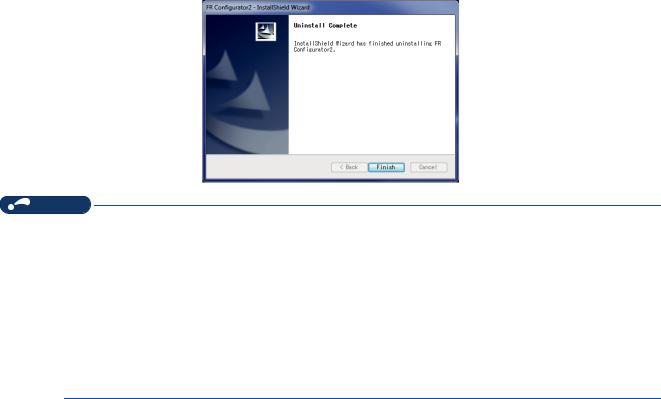
Click [Yes] to proceed the uninstallation. (Click [No] to cancel the uninstallation.) The following window is displayed when the uninstallation is completed. Click [Finish] to close the window.
NOTE
•Uninstallation is unavailable while the application is running. Perform the uninstallation after closing the application.
•For Windows® XP, uninstall the software as follows.
1.Select [Control panel] on the start menu and display the "Add or Remove Programs" window.
2.Select FR Configurator2 and click the [Delete] button.
•For Windows® 8, uninstall the software as follows.
1.Select [Control Panel] from the All Apps list and display Uninstall or change a program.
2.Select FR Configurator2 and click the [Delete] button.
•For Windows® 10, uninstall the software as follows.
1.Right click the Start button to select [Control Panel], and display Uninstall or change a program. Or click [Settings] -> [System] on the Start menu and select Apps & features.
2.Select FR Configurator2 and click the [Delete] button.
22 1. OUTLINE
1.3 Installation and uninstallation

1.4 Connection and parameter setting |
1 |
|
|
|
|
1.4.1Connection method
For FR Configurator2, communication via a USB connector, a PU connector, the RS-485 terminal block, Ethernet, a GOT, or a programmable controller is available. USB connection is initially selected.
•USB connection (Refer to page 26.)
Connect to USB connector (mini B connector) of the inverter. 1:1 connection is supported. Connection with using USB hub is not supported.
|
USB connector |
Personal computer |
USB cable |
(FR Configurator2) |
|
|
USB mini B |
|
connector |
Inverter |
|
•Serial communication (PU connector) (Refer to page 30.)
Connect to PU connector of the inverter. Serial port/RS-485 converter (cable) or USB/RS-485 converter (cable) is required.
|
Serial port |
or |
USB connector |
|
Personal computer |
Serial cable |
|
USB cable |
|
RS-232C RS-485 |
|
USB |
RS-485 |
|
(FR Configurator2) |
|
|||
converter |
|
converter |
||
|
|
|||
PU connector |
PU connector |
|
||
|
Inverter |
|
Inverter |
|
•Ethernet connection (Ethernet connector) (Refer to page 35.)
Connection to the Ethernet connector of the inverter. Up to 120 inverters can be connected using a hub.
Ethernet connector |
|
|
Personal computer |
Ethernet cable |
Up to |
|
||
(FR Configurator2) |
Hub |
120 inverters |
Ethernet |
|
|
connector |
|
|
Inverter |
|
|
1. OUTLINE 23
1.4 Connection and parameter setting

•Serial communication (RS-485 terminal) (Refer to page 41.)
Connect to RS-485 terminal of the inverter. Up to 32 inverters can be connected.
|
Serial port |
|
|
Personal computer |
Serial cable |
|
|
RS--232C RS- |
-485 |
|
|
(FR Configurator2) |
|
||
converter |
|
|
|
|
|
|
|
RS-485 terminal block |
RS-422 / 485 |
Up to |
|
|
32 inverters |
||
|
Inverter |
|
|
•Communication through GOT (USB / Serial communication) (Refer to page 43.)
Through a GOT (Human Machine Interface), connection to the RS-485 terminal block is available. For the GOT1000 series, an RS-422 communication unit is required. For the compatible version of GOT or details of the RS-422/485 connection, refer to the GOT1000/GOT2000 Series Connection Manual.
GOT2000
USB cable
USB connector
Personal computer |
RS-422/485 |
|
|
(FR Configurator2) |
|
|
|
Up to 32 inverters can be connected. |
|||
|
|||
RS-485 terminal block |
|
|
|
|
|
||
•Communication using programmable controller (Ethernet communication) (Refer to page 50.)
A programmable controller (CPU module / Ethernet module) can be used for connecting the inverter.
USB connector, |
|
Serial port, |
|
Ethernet connector |
|
Personal computer |
Programmable controller |
(CPU unit, Ethernet unit) |
|
(FR Configurator2) |
|
Ethernet cable |
|
|
Up to 64 or |
Hub |
120 inverters |
Ethernet connector
Inverter
24 1. OUTLINE
1.4 Connection and parameter setting

• Communication using programmable controller (CC-Link IE Field Network communication) (Refer to page 50.)
A programmable controller (CPU module / Ethernet module) can be used for connecting the inverter. |
1 |
|
|
|
|
USB connector, |
|
|
Serial port, |
|
|
Ethernet connector |
|
|
Personal computer |
Programmable controller |
|
(CPU unit, Ethernet unit) |
|
|
(FR Configurator2) |
|
|
CC-Link IE Field Network communication |
|
|
Ethernet |
Up to |
|
connector |
|
|
|
120 inverters |
|
Inverter
•Communication using programmable controller (CC-Link IE TSN communication) (Refer to page 51.)
A programmable controller (CPU module / Ethernet module) can be used for connecting the inverter.
USB connector, |
Serial port, |
Ethernet connector |
Personal computer
Programmable controller (CPU unit, Ethernet unit)
(FR Configurator2)
CC-Link IE TSN communication
Ethernet connector
Up to 120
inverters
Inverter
•Communication through GOT and programmable controller (Ethernet communication) (Refer to page 50.) Through a GOT (Human Machine Interface) and a programmable controller, connection to the inverter is available.
GOT2000
USB/serial cable
USB connector/ |
Serial port |
Personal computer |
|
Ethernet cable |
|
||||
(FR Configurator2) |
|
|
|||||
|
|
|
|
Programmable controller |
|||
|
|
|
|
(CPU unit, Ethernet unit) |
|||
|
|
|
|
|
|
Up to 64 or 120 |
|
|
Hub |
|
|
|
inverters |
||
|
|
|
|||||
Ethernet |
|
|
|
|
|
|
|
connector |
|
|
|
|
|
|
|
|
|
|
|
|
|
|
|
Inverter
1. OUTLINE 25
1.4 Connection and parameter setting

•Communication through GOT and programmable controller (CC-Link IE Field Network communication) (Refer to page 50.) Through a GOT (Human Machine Interface) and a programmable controller, connection to the inverter is available.
|
|
GOT2000 |
|
|
USB cable |
|
USB connector |
|
Personal computer |
|
Ethernet cable |
(FR Configurator2) |
|
|
|
|
|
Communication |
CC-Link IE Field Network communication |
|
|
||
connector |
|
|
Inverter |
|
Up to |
|
|
120 inverters |
NOTE
•Inserting or pulling out a USB cable during FR Configurator2 operation may cause the inverter to be unrecognized.
Insert and pull out the USB cable for several times, or reset the inverter with the USB cable connected to the personal computer.
•If Pr.999 Automatic parameter setting is changed to "10 or 11" using the operation panel, parameter unit, etc. during FR Configurator2 operation, the inverter communication parameters will be changed, and such setting may disable the communication with FR Configurator2. (For Pr.999, refer to the Instruction Manual (Detailed) of the inverter.)
•Only the USB connection is available for connecting a GOT2000 model to a personal computer.
•The USB driver must be installed for USB communication with the programmable controller CPU. For installing the driver, refer to the Operating Manual of GX Works with the version applicable to the programmable controller CPU.
•The available connection methods differ depending on the inverter. For the details, refer to the Instruction Manual of the inverter.
1.4.2Connection using USB connector
A personal computer and inverter can be easily connected with USB cable. 1:1 connection is supported. Connection using USB hub is not supported.
|
USB connector |
Personal computer |
USB cable |
(FR Configurator2) |
|
|
USB mini B |
|
connector |
Inverter |
|
26 1. OUTLINE
1.4 Connection and parameter setting

800 series
Connect the USB cable to the USB device (mini B connector) on the inverter. |
1 |
|
USB host
(A connector)
Communication status LED
USB device
(mini B connector)
FR-A700, FR-B (700), and FR-B3 (700)
|
|
USB cable |
USB connector |
|
|
|
|
|
|
|
|
|
|
|
|
|
|
|
|
Removal of cover
Place a flathead screwdriver, etc.
in a slot and push up the cover to open.
FR-E700 and FR-E700EX
|
|
USB cable |
USB connector |
|
|
|
|
|
|
|
|
|
|
|
|
How to open the USB connector cover
|
Pull the cover in the direction of arrow. |
Then turn it upward. |
|
|
• Applicable cable |
|
|
|
|
Interface |
|
Conforms to USB 1.1 |
|
|
Transmission speed |
12 Mbps |
|
|
|
Wiring length |
|
Maximum 5 m |
|
|
Connector |
800 series, FR-E700, and FR-E700EX |
USB mini B connector (receptacle) |
|
|
FR-A700, FR-B (700), and FR-B3 (700) |
USB B connector (B receptacle) |
|
|
|
|
|
|
||
Recommended USB cable |
MR-J3USBCBL3M (cable length 3 m) |
|
|
|
|
|
|
1. OUTLINE |
27 |
|
|
|
1.4 Connection and parameter setting |
|

Related parameters for USB connection
Set the following communication parameter when connecting the USB connector of the inverter. When performing parameter writing or run command input, set the following command source parameters, and switch the operation mode to PU operation mode.
Inverter |
Parameter setting |
Operation |
||
Communication parameter |
Command source parameter |
mode |
||
|
||||
FR-A800(-E) |
Pr.548 USB communication check time |
Pr.551 PU mode operation |
|
|
FR-B |
|
|||
command source selection = "3 or |
|
|||
FR-B3 |
interval = "9999" (initial value) |
9999" (initial value: "9999") |
|
|
FR-F800(-E) |
|
|
||
|
|
|
||
FR-A700 |
|
Pr.551 PU mode operation |
PU |
|
FR-E700(SC)(NC) |
|
command source selection = "3 or |
||
|
|
|||
FR-E700EX |
Pr.548 USB communication check time |
9999" (initial value: "9999") |
|
|
FR-B (700) |
interval ≠ "0" (initial value: "9999") |
Pr.551 PU mode operation |
|
|
|
command source selection = "3" |
|
||
FR-B3 (700) |
|
|
||
|
(initial value: "2") |
|
||
|
|
|
||
NOTE
•Set a station number of each inverter in Pr.547 USB communication station number. Perform inverter reset after setting the parameter.
Related parameter list
•800 series
Pr. |
Name |
Initial |
Setting range |
Description |
|
value |
|||||
|
|
|
|
||
547*1 |
USB communication station number |
0 |
0 to 31 |
Inverter station number specification. |
|
N040 |
|||||
|
|
|
|
||
|
|
|
|
USB communication is available, but the inverter |
|
|
|
|
0 |
output is shut off (E.USB) when the mode changes to |
|
|
|
|
|
the PU operation mode. |
|
548*1 |
USB communication check time interval |
9999 |
|
Set the communication check time interval. |
|
N041 |
0.1 to 999.8 s |
If a no-communication state persists for the |
|||
|
|
||||
|
|
|
permissible time or longer, the inverter output is shut |
||
|
|
|
|
||
|
|
|
|
off (E.USB). |
|
|
|
|
9999 |
No communication check |
|
|
|
|
1 |
RS-485 terminals are the command interface enabled |
|
|
|
|
in the PU operation mode. |
||
|
|
|
|
||
|
|
|
2 |
The PU connector is the command interface enabled |
|
|
|
|
in the PU operation mode. |
||
|
|
|
|
||
551*2*3 |
PU mode operation command source |
|
3 |
The USB connector is the command interface enabled |
|
9999 |
in the PU operation mode. |
||||
|
|||||
D013 |
selection |
|
|
||
5 |
The Ethernet connector is the command interface |
||||
|
|||||
|
|
|
enabled in the PU operation mode. |
||
|
|
|
|
||
|
|
|
|
USB automatic recognition |
|
|
|
|
9999 |
Basically, the operation panel (PU connector) is the |
|
|
|
|
command interface. When the USB connector is used, |
||
|
|
|
|
||
|
|
|
|
it is the command interface. |
|
|
*1 Changed settings are enabled at the next power-ON or inverter reset. |
|
|||
|
*2 Pr. 551 is always write-enabled. |
|
|
|
|
|
*3 The setting range depends on the inverter. For the details, refer to the Instruction Manual of the inverter. |
||||
28 1. OUTLINE
1.4 Connection and parameter setting

• 700 series
Pr. |
Name |
Initial |
Setting range |
Description |
1 |
value |
|||||
547*1 |
USB communication station number |
0 |
0 to 31 |
Inverter station number specification. |
|
|
|
|
0 |
USB communication is possible. Trips in the PU |
|
|
|
|
operation mode (E.USB) |
|
|
|
|
|
|
|
|
548*1 |
USB communication check time interval |
|
|
Set the communication check time interval. |
|
9999 |
0.1 to 999.8 s |
If a no-communication state persists for the |
|
||
|
|
|
permissible time or longer, the inverter output is shut |
|
|
|
|
|
|
|
|
|
|
|
|
off (E.USB). |
|
|
|
|
9999 |
No communication check |
|
|
|
|
1 |
The RS-485 terminals are the command interface |
|
|
|
|
enabled in the PU operation mode. |
|
|
|
|
|
|
|
|
|
|
|
2 |
The PU connector is the command interface enabled |
|
|
|
|
in the PU operation mode. |
|
|
|
|
|
|
|
|
|
PU mode operation command source |
|
3 |
The USB connector is the command interface enabled |
|
551*2*3 |
9999 |
in the PU operation mode. |
|
||
|
|
||||
selection |
|
|
|
||
4 |
The operation panel is the command interface |
|
|||
|
|
|
|||
|
|
|
enabled in the PU operation mode. |
|
|
|
|
|
|
|
|
|
|
|
|
USB automatic recognition |
|
|
|
|
9999 |
Basically, the operation panel (PU connector) is the |
|
|
|
|
command interface. When the USB connector is used, |
|
|
|
|
|
|
|
|
|
|
|
|
it is the command source. |
|
*1 Changed settings are enabled at the next power-ON or inverter reset. *2 Pr.551 can be always written regardless of the operation mode.
*3 The initial value and the setting range differ depending on the inverter. For the details, refer to the Instruction Manual of the inverter.
NOTE
•Always reset the inverter after making the setting of the parameters. After you have changed the communication-related parameters, communication cannot be established until the inverter reset.
When connecting USB for the first time
If a personal computer and inverter are connected via USB for the first time with the inverter power ON, "Found New Hardware Wizard" window is displayed.
The following additional wizard is displayed for Windows® XP.
1. Select "No, not this time", and click [Next].
2. Select "Install the software automatically (Recommended)" and click [Next].
1. OUTLINE 29
1.4 Connection and parameter setting
Loading...