


Mitsubishi SUZ-KA25VA2.TH, SUZ-KA35VA2.TH, SUZ-KA50VA2.TH, SUZ-KA60VA2.TH, SUZ-KA71VA2.TH Service Manual
SPLIT-TYPE, HEAT PUMP AIR CONDITIONERS
TECHNICAL & SERVICE MANUAL
May 2010
No.OCH472
HFC
utilized
R410A
R410A
Outdoor unit
[model names] [Service Ref.]
SUZ-KA25VA2 SUZ-KA35VA2 SUZ-KA50VA2 SUZ-KA60VA2 SUZ-KA71VA2
SUZ-KA25VA2.TH SUZ-KA35VA2.TH SUZ-KA50VA2.TH SUZ-KA60VA2.TH SUZ-KA71VA2.TH
 Indication of
model name
SUZ-KA25VA2.TH
SUZ-KA35VA2.TH
NOTE:
This service manual describes technical data of the outdoor units.
RoHS compliant products have <G> mark on the spec name plate.
For servicing of RoHS compliant products, refer to the RoHS Parts List.
CONTENTS
1. |
COMBINATION OF INDOOR AND OUTDOOR UNITS |
....... |
|||||||
|
2 |
||||||||
2. TECHNICAL CHANGES |
.................................... |
||||||||
|
|
|
|
|
3 |
||||
3. PART NAMES AND FUNCTIONS |
...................... |
||||||||
|
|
6 |
|||||||
4. |
SPECIFICATION.................................................7 |
||||||||
5. |
NOISE CRITERIA CURVES............................... 9 |
||||||||
6. OUTLINES AND DIMENSIONS |
........................ |
||||||||
|
|
|
|
10 |
|||||
7. WIRING DIAGRAM |
........................................... |
||||||||
|
|
|
|
|
|
|
13 |
||
8. |
REFRIGERANT SYSTEM DIAGRAM.............. |
17 |
|||||||
9. ACTUATOR CONTROL....................................21 |
|||||||||
10. SERVICE FUNCTIONS |
..................................... |
||||||||
|
|
|
|
|
|
22 |
|||
11. TROUBLESHOOTING...................................... |
22 |
||||||||
12. DISASSEMBLY INSTRUCTIONS |
..................... |
63 |
|||||||
|
|
|
|||||||
PARTS CATALOG (OCB472)
1 
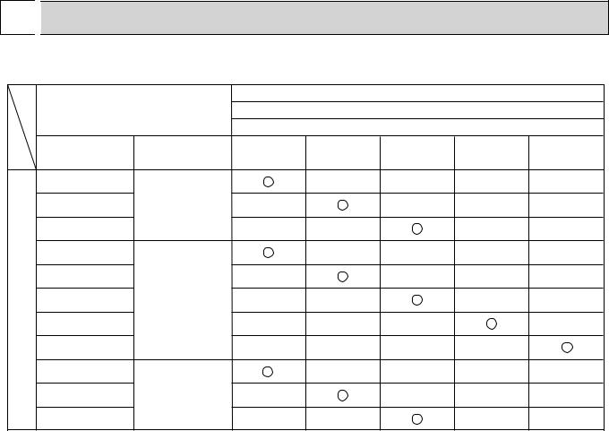
 COMBINATION OF INDOOR AND OUTDOOR UNITS
1-1. INDOOR UNIT SERVICE MANUAL
|
|
|
|
|
Outdoor unit |
|
|
|
Indoor unit |
|
Heat pump type |
|
|||
|
|
Service |
|
|
SUZ- |
|
|
|
Service Ref. |
KA25VA2.TH |
KA35VA2.TH |
KA50VA2.TH |
KA60VA2.TH |
KA71VA2.TH |
|
|
Manual No. |
||||||
|
|
|
|
|
|
|
|
|
SLZ-KA25VA(L).TH |
|
|
— |
— |
— |
— |
heater |
SLZ-KA35VA(L).TH |
OC320 |
— |
|
— |
— |
— |
SLZ-KA50VA(L).TH |
|
— |
— |
|
— |
— |
|
electric |
SEZ-KD25VA(L).TH |
|
|
— |
— |
— |
— |
SEZ-KD35VA(L).TH |
|
— |
|
— |
— |
— |
|
without |
HWE0711 |
|
|||||
SEZ-KD50VA(L).TH |
— |
— |
|
— |
— |
||
|
|
||||||
SEZ-KD60VA(L).TH |
|
— |
— |
— |
|
— |
|
pump |
|
|
|||||
SEZ-KD71VA(L).TH |
|
— |
— |
— |
— |
|
|
|
|
|
|
|
|
|
|
Heat |
MFZ-KA25VA-E4 |
|
|
— |
— |
— |
— |
MFZ-KA35VA-E4 |
OB409 |
— |
|
— |
— |
— |
|
|
|
||||||
|
MFZ-KA50VA-E4 |
|
— |
— |
|
— |
— |
(NOTE) • Please refer to the service manual of indoor unit or the technical data book for the combination data.
2

2 
 TECHNICAL CHANGES
INFORMATION FOR THE AIR CONDITIONER WITH R410A REFRIGERANT
•This room air conditioner adopts an HFC refrigerant (R410A) which never destroys the ozone layer.
•Pay particular attention to the following points, though the basic installation procedure is same as that for R22 conditioners.
1As R410A has working pressure approximate 1.6 times as high as that of R22, some special tools and piping parts/ materials are required. Refer to the table below.
2Take sufficient care not to allow water and other contaminations to enter the R410A refrigerant during storage and installation, since it is more susceptible to contaminations than R22.
3For refrigerant piping, use clean, pressure-proof parts/materials specifically designed for R410A. (Refer to 2. Refrigerant piping.)
4Composition change may occur in R410A since it is a mixed refrigerant. When charging, charge liquid refrigerant to prevent composition change.
|
|
|
|
New refrigerant |
Previous refrigerant |
|
Refrigerant |
|
|
R410A |
R22 |
|
Composition (Ratio) |
|
|
HFC-32: HFC-125 (50%:50%) |
R22 (100%) |
|
Refrigerant handling |
|
|
Pseudo-azeotropic refrigerant |
Single refrigerant |
|
Chlorine |
|
|
Not included |
Included |
|
Safety group (ASHRAE) |
|
|
A1/A1 |
A1 |
Refrigerant |
Molecular weight |
|
|
72.6 |
86.5 |
Saturated steam density [25 |
](Kg/*) |
|
64 |
44.4 |
|
|
Boiling point ( ) |
|
|
-51.4 |
-40.8 |
|
Steam pressure [25 ](Mpa) |
|
1.557 |
0.94 |
|
|
|
|
|
|
|
|
Combustibility |
|
|
Non combustible |
Non combustible |
|
ODP +1 |
|
|
0 |
0.055 |
|
GWP +2 |
|
|
1730 |
1700 |
|
Refrigerant charge method |
|
|
From liquid phase in cylinder |
Gas phase |
|
Additional charge on leakage |
|
Possible |
Possible |
|
Refrigerant oil |
Kind |
|
|
Incompatible oil |
Compatible oil |
Smell |
|
|
None |
None |
|
|
Color |
|
|
None |
Light yellow |
|
|
|
|
|
|
+1: Ozone Depletion Potential |
: based on CFC-11 |
|
|||
+2: Global Warming Potential |
: based on CO2 |
|
|
||
Compressor
|
New Specification |
Current Specification |
|||||||||||||
The incompatible refrigerant oil easily separates from |
Since refrigerant and refrigerant oil are compatible with |
||||||||||||||
refrigerant and is in the upper layer inside the suction muffler. |
each other, refrigerant oil backs to the compressor through |
||||||||||||||
Raising position of the oil back hole enables to back the |
the lower position oil back hole. |
||||||||||||||
refrigerant oil of the upper layer to flow back to the |
|
|
|
|
|
|
|
||||||||
compressor. |
|
|
|
|
|
|
Suction muffler |
|
|
|
|
|
|
Suction muffler |
|
|
|
|
|
|
|
|
|
|
|
|
|||||
|
|
|
|
|
|
|
Oil back hole |
|
|
|
|
|
|
|
|
Compressor |
|
|
|
|
|
|
Compressor |
|
|
||||||
|
|
|
|
|
|
|
|
Refrigerant oil |
|
|
|
|
|
|
Oil back hole |
|
|
|
|
|
|
|
|
|
|
|
|
|
|||
|
|
|
|
|
|
|
|
||||||||
Refrigerant oil /Refrigerant
NOTE : The unit of pressure has been changed to MPa on the international system of units (SI unit system). The conversion factor is: 1 (MPa [Gauge]) =10.2 (kgf/cm2 [Gauge])
3

Conversion chart of refrigerant temperature and pressure
(MPa [Gauge])
|
4.0 |
|
|
|
|
|
|
|
|
|
|
|
|
|
|
|
|
|
|
|
|
|
|
|
|
|
|
|
|
|
|
|
|
|
3.5 |
|
|
|
|
|
|
|
|
|
|
|
|
|
|
|
pressure |
|
|
|
|
|
|
R410A |
|
|
|
|
|
|
|||
|
|
|
|
|
|
|
|
|
|
|
|
|||||
|
|
|
|
|
|
|
|
|
|
|
|
|
||||
3.0 |
|
|
|
|
|
|
R22 |
|
|
|
|
|
|
|||
|
|
|
|
|
|
|
|
|
|
|
|
|
||||
liquid |
2.5 |
|
|
|
|
|
|
|
|
|
|
|
|
|
|
|
|
|
|
|
|
|
|
|
|
|
|
|
|
|
|
||
|
|
|
|
|
|
|
|
|
|
|
|
|
|
|
||
2.0 |
|
|
|
|
|
|
|
|
|
|
|
|
|
|
NOTE: The unit of pressure has been changed to MPa on the |
|
|
|
|
|
|
|
|
|
|
|
|
|
|
|
|||
1.5 |
|
|
|
|
|
|
|
|
|
|
|
|
|
|
||
Saturated |
|
|
|
|
|
|
|
|
|
|
|
|
|
|
||
1.0 |
|
|
|
|
|
|
|
|
|
|
|
|
|
|
international system of units (SI unit system). |
|
|
|
|
|
|
|
|
|
|
|
|
|
|
|
|
||
|
|
|
|
|
|
|
|
|
|
|
|
|
|
|
The conversion factor is: 1 (MPa [Gauge]) =10.2 (kgf/cm2 [Gauge]) |
|
|
|
|
|
|
|
|
|
|
|
|
|
|
|
|
||
|
0.5 |
|
|
|
|
|
|
|
|
|
|
|
|
|
|
|
|
|
|
|
|
|
|
|
|
|
|
|
|
|
|
|
|
|
0.0 |
|
|
|
|
|
|
|
|
|
|
|
|
|
|
|
|
|
|
|
|
|
|
|
|
|
|
|
|
|
|
|
|
|
-0.5 |
|
|
|
|
|
|
|
|
|
|
|
|
|
|
|
|
-30 |
-20 -10 0 10 20 30 40 50 60 ( ) |
||||||||||||||
1. Tools dedicated for the air conditioner with R410A refrigerant
The following tools are required for R410A refrigerant. Some R22 tools can be substituted for R410A tools.
The diameter of the service port on the stop valve in outdoor unit has been changed to prevent any other refrigerant being charged into the unit. Cap size has been changed from 7/16 UNF with 20 threads to 1/2 UNF with 20 threads.
R410A tools |
Can R22 tools be used? |
Description |
|
|
|
R410A has high pressures beyond the measurement range of existing |
|
Gauge manifold |
No |
gauges. Port diameters have been changed to prevent any other refrigerant |
|
|
|
from being charged into the unit. |
|
Charge hose |
No |
Hose material and cap size have been changed to improve the pressure |
|
resistance. |
|||
|
|
||
Gas leak detector |
No |
Dedicated for HFC refrigerant. |
|
Torque wrench |
Yes |
6.35 mm and 9.52 mm |
|
No |
12.7 mm and 15.88 mm |
||
|
|||
Flare tool |
Yes |
Clamp bar hole has been enlarged to reinforce the spring strength in the tool. |
|
Flare gauge |
New |
Provided for flaring work (to be used with R22 flare tool). |
|
Vacuum pump |
New |
Provided to prevent the back flow of oil. This adapter enables you to use |
|
adapter |
vacuum pumps. |
||
|
|||
Electronic scale for |
New |
It is difficult to measure R410A with a charging cylinder because the |
|
refrigerant charging |
refrigerant bubbles due to high pressure and high-speed vaporization |
||
|
No: Not substitutable for R410A Yes: Substitutable for R410A
4

2. Refrigerant piping
1Specifications
Use the refrigerant pipes that meet the following specifications.
Pipe |
Outside diameter |
Wall thickness |
Insulation material |
|
mm |
mm |
|||
|
|
|||
For liquid |
6.35 |
0.8 |
Heat resisting foam plastic |
|
9.52 |
0.8 |
|||
|
||||
|
9.52 |
0.8 |
Specific gravity 0.045 Thickness |
|
For gas |
12.7 |
0.8 |
8 mm |
|
|
15.88 |
1.0 |
|
•Use a copper pipe or a copper-alloy seamless pipe with a thickness of 0.8 mm. Never use any pipe with a thickness less than 0.8mm, as the pressure resistance is insufficient.
2Flaring work and flare nut
Flaring work for R410A pipe differs from that for R22 pipe.
For details of flaring work, refer to Installation manual “FLARING WORK”.
Pipe diameter (mm) |
Dimension of flare nut (mm) |
|
|
|
|
|
R410A |
R22 |
6.35 |
17 |
17 |
9.52 |
22 |
22 |
12.7 |
26 |
24 |
15.88 |
29 |
27 |
3. Refrigerant oil
Apply the special refrigerant oil (accessories: packed with indoor unit) to the flare and the union seat surfaces.
4. Air purge
 Do not discharge the refrigerant into the atmosphere.
Take care not to discharge refrigerant into the atmosphere during installation, reinstallation, or repairs to the refrigerant circuit.
 Use the vacuum pump for air purging for the purpose of environmental protection.
5. Additional charge
For additional charging, charge the refrigerant from liquid phase of the gas cylinder.
If the refrigerant is charged from the gas phase, composition change may occur in the refrigerant inside the cylinder and the outdoor unit. In this case, ability of the refrigerating cycle decreases or normal operation can be impossible. However,
charging the liquid refrigerant all at once may cause the compressor to be locked. Thus, charge the refrigerant slowly.
Indoor unit
Refrigerant gas cylinder operating valve
Union
|
Stop valve |
Liquid pipe |
|
Gas pipe |
Outdoor unit |
Service port
Gauge manifold valve (for R410A)
 Charge hose (for R410A)
Refrigerant gas cylinder for R410A with siphon
Refrigerant (liquid)
Electronic scale for refrigerant charging
5

3 
 PART NAMES AND FUNCTIONS
SUZ-KA25VA2.TH SUZ-KA35VA2.TH
Air inlet (back and side)
Piping
Drain hose
Air outlet
Drain outlet
SUZ-KA50VA2.TH SUZ-KA60VA2.TH
Air inlet (back and side)
Piping
Drain hose
Air outlet
Drain outlet
SUZ-KA71VA2.TH
Air inlet (back and side)
|
|
Piping |
|
|
|
Drain hose |
|
|
|
Air outlet |
|
|
|
Drain outlet |
|
Model |
SUZ-KA25/35VA2.TH |
SUZ-KA50/60VA2.TH |
SUZ-KA71VA2.TH |
Drain socket |
1 |
1 |
1 |
Drain cap |
- |
2 |
- |
6

4 
 SPECIFICATION
|
|
Outdoor Service Ref. |
|
SUZ-KA25VA2.TH |
SUZ-KA35VA2.TH |
SUZ-KA50VA2.TH |
SUZ-KA60VA2.TH |
SUZ-KA71VA2.TH |
||||||||||||
|
|
|
|
|
|
|
|
|
|
|
|
|
|
|
|
|
|
|||
|
|
|
|
|
|
|
|
|
|
|
|
|
|
|
||||||
|
|
Function |
|
|
Cooling Heating |
Cooling |
Heating |
Cooling |
Heating |
Cooling |
Heating |
Cooling |
Heating |
|||||||
|
|
Power supply |
|
Single phase |
Single phase |
Single phase |
Single phase |
Single phase |
||||||||||||
|
|
|
230V, 50Hz |
230V, 50Hz |
230V, 50Hz |
230V, 50Hz |
230V, 50Hz |
|||||||||||||
|
|
|
|
|
|
|||||||||||||||
Electrical data |
Starting current |
*1 |
A |
3.65 |
4.75 |
6.75 |
9.75 |
8.89 |
||||||||||||
Fan motor current |
*1 |
A |
0.31 |
0.28 |
0.33 |
|
0.33 |
0.30 |
0.30 |
0.83 |
|
0.82 |
||||||||
|
|
Compressor motor current *1 |
A |
2.74 |
3.37 |
4.22 |
|
4.42 |
6.45 |
6.05 |
8.05 |
9.45 |
8.00 |
|
8.07 |
|||||
|
|
|
|
|
|
|
|
|
|
|
|
|
|
|
|
|
|
|
|
|
Compressor |
Model |
|
|
|
KNB073FFDH(C) |
KNB092FFAH(C) |
SNB130FGBH(T) |
SNB130FGBH(T) |
SNB172FEKMT |
|||||||||||
resistance (at 20 |
|
) |
W |
V-W 1.70 |
V-W 1.91 |
V-W 0.98 |
V-W 0.98 |
V-W 1.04 |
||||||||||||
|
|
Output |
|
|
550 |
650 |
900 |
900 |
1200 |
|||||||||||
|
|
Winding |
|
|
|
U-V 1.70 |
|
U-W 1.70 |
U-V 1.91 |
|
U-W 1.91 |
U-V 0.98 |
|
U-W 0.98 |
U-V 0.98 |
|
U-W 0.98 |
U-V 1.04 |
|
U-W 1.04 |
|
|
|
|
|
|
|
|
|
|
|
|
|
|
|
|
|||||
Fan motor |
Model |
|
|
|
RC0J50-DB |
RC0J50-DB |
RC0J60-AA |
RC0J60-AA |
RC0J60-BC |
|||||||||||
Winding |
|
|
|
WHT-BLK 37.0 |
WHT-BLK 37.0 |
WHT-BLK 15.2 |
WHT-BLK 15.2 |
WHT-BLK 15.0 |
||||||||||||
|
|
BLK-RED 37.0 |
BLK-RED 37.0 |
BLK-RED 15.2 |
BLK-RED 15.2 |
BLK-RED 15.0 |
||||||||||||||
|
|
|
|
|
|
|
|
|
|
|
|
|
|
|
|
|
|
|
|
|
|
|
resistance(at 20 |
) |
|
RED-WHT 37.0 |
RED-WHT 37.0 |
RED-WHT 15.2 |
RED-WHT 15.2 |
RED-WHT 15.0 |
|||||||||||
|
|
|
|
|
|
|||||||||||||||
|
|
Air flow(High/Low+) |
*/h |
2,058 |
|
1,938 |
2,004 |
2,940/1,650+ |
2,940/2,210+ |
2,940/1,650+ |
2,940/2,210+ |
3,.425/3,006 |
|
2,892/2,892 |
||||||
|
|
|
|
|
|
|
|
|
|
|
|
|
|
|
|
|
|
/1,512+ |
|
/2,280+ |
|
|
Dimensions W H D |
mm |
800%550%285 |
800%550%285 |
840%850%330 |
840%850%330 |
840%880%330 |
||||||||||||
|
|
Weight |
|
|
kg |
|
30 |
|
33 |
|
53 |
|
53 |
53 |
||||||
|
|
Sound level *1 |
|
|
dB |
|
46 |
47 |
|
48 |
53/51+ |
|
55/53+ |
53/51+ |
|
55/53+ |
55+ |
|
55+ |
|
Special remarks |
|
Fanspeed(High+/Low+,High+/Med+/Low+) rpm |
810+/650+880+/810+/650+ |
840+/760+ |
880+/800+/630+ |
840/480+ |
800/620+ |
840/480+ |
800/620+ |
950/840/450+ |
|
810/810/650+ |
||||||||
|
Refrigerant filling |
|
|
kg |
0.80 |
1.05 |
1.60 |
1.80 |
1.80 |
|||||||||||
|
|
Fan speed regulator |
|
2 |
3 |
2 |
3 |
|
2 |
|
2 |
|
3 |
|||||||
|
|
capacity(R410A) |
|
|
|
|
|
|
|
|
|
|
|
|
|
|
|
|
|
|
|
|
Refrigerating oil (Model) |
cc |
320 (NEO22) |
320 (NEO22) |
450 (NEO22) |
450 (NEO22) |
400 (FV50S) |
||||||||||||
|
|
|
|
|
|
|
|
|
|
|
|
|
|
|
|
|
||||
NOTE : Test conditions are based on ISO 5151 |
|
|
|
|
|
|
|
|
|
|
|
|
||||||||
|
|
Cooling : Indoor |
D.B. 27: W.B. 19: |
|
|
|
|
|
|
|
|
|
|
|
|
|||||
|
|
Outdoor D.B. 35: W.B. 24: |
|
|
|
|
|
|
|
|
|
|
|
|
||||||
|
|
Heating : Indoor |
D.B. 20: W.B. 15: |
|
|
|
|
|
|
|
|
|
|
|
|
|||||
|
|
Outdoor D.B. 7: W.B. 6: |
|
|
|
|
|
|
|
|
|
|
|
|
||||||
|
|
Refrigerant piping length (one way): 5m |
|
|
|
|
|
|
|
|
|
|
|
|
||||||
|
|
*1 Measured under rated operating frequency. |
|
|
|
|
|
|
|
|
|
|
|
|
||||||
|
|
w Reference value |
|
|
|
|
|
|
|
|
|
|
|
|
|
|
|
|
||
7

Specifications and rating conditions of main electric parts
SUZ-KA25VA2.TH SUZ-KA35VA2.TH
SUZ-KA50VA2.TH SUZ-KA60VA2.TH
SUZ-KA71VA2.TH
|
Model |
SUZ-KA25VA2. |
SUZ0KA35VA2. |
SUZ-KA50VA2. |
SUZ-KA60VA2. |
SUZ-KA71VA2. |
|||
Item |
|
TH |
|
TH |
|
TH |
TH |
|
TH |
|
(CT) |
|
|
20A |
|
|
- |
|
- |
Current |
(CT1, 2) |
|
- |
|
|
ETQ19Z68AY |
|
- |
|
transformer |
(CT61) |
|
- |
|
|
ETQ19Z53AY |
|
- |
|
|
(CT761, CT781) |
|
|
15A |
|
|
- |
|
- |
Smoothing |
(C61) |
|
- |
|
620+ 420V |
- |
|
- |
|
(C62, C63) |
|
|
620+ 420V |
|
|
- |
|
- |
|
capacitor |
|
|
|
|
|
||||
(CB1, 2, 3) |
|
- |
|
|
560μF 450V |
|
560μF 350V |
||
|
|
|
|
|
|||||
Diode module |
(DB61) |
15A 600V |
|
25A 600V |
- |
|
- |
||
(DB65) |
|
|
25A 600V |
|
|
- |
|
- |
|
|
|
|
|
|
|
||||
|
(F61) |
|
|
T20A L250V |
|
|
- |
|
- |
|
(F62) |
|
- |
|
|
- |
|
T20A L250V |
|
Fuse |
(F63) |
|
- |
|
|
- |
|
- |
|
(F64) |
|
- |
|
|
250V 2A |
|
- |
||
|
|
|
|
|
|||||
|
(F701, F801, F901) |
|
|
T3.15A L250V |
|
|
- |
||
|
(F911) |
|
- |
|
|
250V 1A |
|
- |
|
Inteligent power |
(IPM) |
15A 600V |
|
20A 600V |
15A 600V |
|
20A 600V |
||
(HC930) |
|
- |
|
|
3A 450V |
|
- |
||
module |
|
|
|
|
|||||
(IC932) |
|
|
|
- |
|
|
5A 600V |
||
|
|
|
|
|
|
||||
Power factor |
(PFC) |
|
- |
|
|
PS51259-A |
|
20A 600V |
|
controller |
|
|
|
|
|||||
|
|
|
|
|
|
|
|
|
|
Expansion valve |
(LEV) |
|
|
|
|
DC12V |
|
|
|
coil |
|
|
|
|
|
|
|
||
|
|
|
|
|
|
|
|
|
|
High pressure |
(HPS) |
|
- |
|
|
ACB-DB156 |
|
- |
|
switch |
|
|
|
(for R2) |
|
||||
|
|
|
|
|
|
|
|
||
Reactor |
(L61) |
|
|
23mH |
|
|
|
- |
|
(L) |
|
- |
|
|
340μH 20A |
|
340μH |
||
|
|
|
|
|
|||||
|
(R61) |
45mΩ 5W |
|
100mΩ 5W |
|
|
- |
|
|
|
(1 element) |
|
(2 elements) |
|
|
|
|
||
|
|
|
|
|
|
|
|
||
|
(R61, R62) |
|
- |
|
180mΩ 5W |
|
- |
||
Current-detecting |
|
|
(2 elements) |
|
|||||
|
|
|
|
|
|
|
|
||
resistor |
(R64A, R64B) |
|
- |
|
|
10Ω 10W |
|
|
|
|
(R825) |
|
|
25mΩ 5W |
|
|
|
- |
|
|
(R937, R938, R939) |
430mΩ 2W |
|
|
- |
|
|
||
|
(R937A, R937B) |
|
- |
|
1.1Ω 2W |
1.1Ω 2W 2% |
|
- |
|
Resistor |
(RS1~4) |
|
- |
|
|
0.04Ω 7W |
|
- |
|
Current-Limiting |
(PTC64, PTC65) |
|
|
33Ω |
|
|
- |
|
33Ω |
PTC thermistoe |
|
|
|
|
|
||||
|
|
|
|
|
|
|
|
|
|
Terminal block |
(TB1, TB2) |
|
|
|
|
3P |
|
|
|
|
(X63) |
|
|
3A 250V |
|
|
|
- |
|
Relay |
(X64) |
|
|
20A 250V |
|
|
20A 250V |
|
20A 250V |
(X601) |
|
|
|
- |
|
|
3A 250V |
||
|
|
|
|
|
|
||||
|
(X602) |
|
|
|
- |
|
|
3A 250V |
|
Solenoid coil relay |
(SSR61) |
|
- |
|
|
TLP3506 |
|
- |
|
R.V. coil |
(21S4) |
|
|
|
|
AC220-240V |
|
|
|
IGBT |
(TR821) |
|
|
30A 600V |
|
|
- |
|
- |
8

5 
 NOISE CRITERIA CURVES
SUZ-KA25VA2.TH
|
FAN SPEED |
FUNCTION |
SPL(dB(A)) |
|
LINE |
||
|
|
|
|
|
|
|
|
|
High |
COOLING |
46 |
|
|
|
|
|
|
||||||
|
Med. |
HEATING |
46 |
|
|
|
|
|
|
|
|
|
|||
|
|
|
|
|
|
|
|
Test conditions, |
|
|
|
|
|
|
|
Cooling : Dry-bulb temperature 35 |
Wet-bulb temperature (24 ) |
||||||
Heating : Dry-bulb temperature 7 |
Wet-bulb temperature 6 |
||||||
BAR |
90 |
|
|
|
|
|
|
|
|
|
|
|
|
|
|
|
|
|
|
0.0002 MICRO |
80 |
|
|
|
|
|
|
|
|
70 |
|
|
|
|
|
|
|
NC-70 |
|
dB re |
60 |
|
|
|
|
|
|
|
|
LEVEL, |
|
|
|
|
|
|
|
|
|
|
|
|
|
|
|
|
|
NC-60 |
|
50 |
|
|
|
|
|
|
|
|
|
PRESSURE |
|
|
|
|
|
|
|
|
|
|
|
|
|
|
|
|
|
NC-50 |
|
40 |
|
|
|
|
|
|
|
|
|
|
|
|
|
|
|
|
|
NC-40 |
|
SOUND |
|
|
|
|
|
|
|
|
|
30 |
|
|
|
|
|
|
|
|
|
BAND |
|
|
|
|
|
|
|
|
NC-30 |
20 |
APPROXIMATE |
|
|
|
|
|
|
||
OCTAVE |
|
|
|
|
|
|
|||
|
THRESHOLD OF |
|
|
|
|
|
|
||
|
HEARING FOR |
|
|
|
|
|
NC-20 |
||
|
CONTINUOUS |
|
|
|
|
|
|
||
10 |
NOISE |
|
|
|
|
|
|
|
|
|
63 |
125 |
250 |
500 |
1000 |
2000 |
4000 |
8000 |
|
|
|
||||||||
BAND CENTER FREQUENCIES, Hz
SUZ-KA35VA2.TH
|
FAN SPEED |
FUNCTION |
SPL(dB(A)) |
|
LINE |
||
|
|
|
|
|
|
|
|
|
High |
COOLING |
47 |
|
|
|
|
|
|
||||||
|
Med. |
HEATING |
48 |
|
|
|
|
|
|
|
|
|
|||
|
|
|
|
|
|
|
|
Test conditions, |
|
|
|
|
|
|
|
Cooling : Dry-bulb temperature 35 |
Wet-bulb temperature (24 ) |
||||||
Heating : Dry-bulb temperature 7 |
Wet-bulb temperature 6 |
||||||
BAR |
90 |
|
|
|
|
|
|
|
|
|
|
|
|
|
|
|
|
|
|
0.0002 MICRO |
80 |
|
|
|
|
|
|
|
|
70 |
|
|
|
|
|
|
|
NC-70 |
|
dB re |
60 |
|
|
|
|
|
|
|
|
LEVEL, |
|
|
|
|
|
|
|
|
|
|
|
|
|
|
|
|
|
NC-60 |
|
50 |
|
|
|
|
|
|
|
|
|
PRESSURE |
|
|
|
|
|
|
|
|
|
|
|
|
|
|
|
|
|
NC-50 |
|
40 |
|
|
|
|
|
|
|
|
|
|
|
|
|
|
|
|
|
NC-40 |
|
SOUND |
|
|
|
|
|
|
|
|
|
30 |
|
|
|
|
|
|
|
|
|
BAND |
|
|
|
|
|
|
|
|
NC-30 |
20 |
APPROXIMATE |
|
|
|
|
|
|
||
OCTAVE |
|
|
|
|
|
|
|||
|
THRESHOLD OF |
|
|
|
|
|
|
||
|
HEARING FOR |
|
|
|
|
|
NC-20 |
||
|
CONTINUOUS |
|
|
|
|
|
|
||
10 |
NOISE |
|
|
|
|
|
|
|
|
|
63 |
125 |
250 |
500 |
1000 |
2000 |
4000 |
8000 |
|
|
|
||||||||
BAND CENTER FREQUENCIES, Hz
SUZ-KA50VA2.TH SUZ-KA60VA2.TH |
SUZ-KA71VA2.TH |
FAN SPEED FUNCTION SPL(dB(A)) |
LINE |
COOLING 53
High
HEATING 55
FAN SPEED FUNCTION SPL(dB(A)) |
LINE |
COOLING 55
High
HEATING 55
Test conditions, |
|
|
Cooling : Dry-bulb temperature 35 |
|
Wet-bulb temperature (24 ) |
Heating : Dry-bulb temperature 7 |
|
Wet-bulb temperature 6 |
BAR |
90 |
|
|
|
|
|
|
|
|
|
|
|
|
|
|
|
|
|
|
0.0002 MICRO |
80 |
|
|
|
|
|
|
|
|
70 |
|
|
|
|
|
|
|
NC-70 |
|
dB re |
60 |
|
|
|
|
|
|
|
|
LEVEL, |
|
|
|
|
|
|
|
|
|
|
|
|
|
|
|
|
|
NC-60 |
|
50 |
|
|
|
|
|
|
|
|
|
PRESSURE |
|
|
|
|
|
|
|
|
|
|
|
|
|
|
|
|
|
NC-50 |
|
40 |
|
|
|
|
|
|
|
|
|
|
|
|
|
|
|
|
|
NC-40 |
|
SOUND |
|
|
|
|
|
|
|
|
|
30 |
|
|
|
|
|
|
|
|
|
BAND |
|
|
|
|
|
|
|
|
NC-30 |
20 |
APPROXIMATE |
|
|
|
|
|
|
||
OCTAVE |
|
|
|
|
|
|
|||
|
THRESHOLD OF |
|
|
|
|
|
|
||
|
HEARING FOR |
|
|
|
|
|
NC-20 |
||
|
CONTINUOUS |
|
|
|
|
|
|
||
10 |
NOISE |
|
|
|
|
|
|
|
|
|
63 |
125 |
250 |
500 |
1000 |
2000 |
4000 |
8000 |
|
|
|
||||||||
Test conditions, |
|
|
Cooling : Dry-bulb temperature 35 |
|
Wet-bulb temperature (24 ) |
Heating : Dry-bulb temperature 7 |
|
Wet-bulb temperature 6 |
BAR |
90 |
|
|
|
|
|
|
|
|
|
|
|
|
|
|
|
|
MICRO |
80 |
|
|
|
|
|
|
|
|
|
|
|
|
|
|
|
|
0.0002 |
70 |
|
|
|
|
|
|
NC-70 |
|
|
|
|
|
|
|
||
0dB re |
|
|
|
|
|
|
|
|
60 |
|
|
|
|
|
|
|
|
LEVEL, |
|
|
|
|
|
|
|
|
|
|
|
|
|
|
|
NC-60 |
|
50 |
|
|
|
|
|
|
|
|
PRESSURE |
|
|
|
|
|
|
|
|
|
|
|
|
|
|
|
NC-50 |
|
40 |
|
|
|
|
|
|
|
|
|
|
|
|
|
|
|
NC-40 |
|
SOUND |
|
|
|
|
|
|
|
|
30 |
|
|
|
|
|
|
|
|
|
|
|
|
|
|
|
NC-30 |
|
BAND |
|
|
|
|
|
|
|
|
20 |
|
|
|
|
|
|
|
|
OCTAVE |
|
|
|
|
|
|
|
|
|
|
|
|
NC-10 |
|
NC-20 |
||
|
|
|
|
|
|
|||
10 |
|
|
|
|
|
|
|
|
|
125 |
250 |
500 |
1000 |
2000 |
4000 |
8000 |
|
|
63 |
|||||||
BAND CENTER FREQUENCIES, Hz |
|
BAND CENTER FREQUENCIES, Hz |
Test conditions |
|
OUTDOOR UNIT |
Cooling: Dry-bulb temperature 35°C |
|
|
Heating: Dry-bulb temperature |
7°C |
1 m |
Wet-bulb temperature |
6°C |
|
MICROPHONE
9

6 
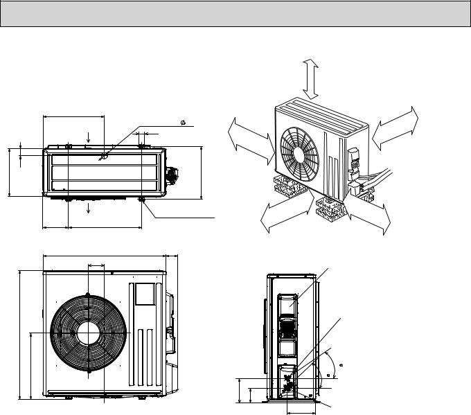
 OUTLINES AND DIMENSIONS
SUZ-KA25VA2.TH SUZ-KA35VA2.TH
REQUIRED SPACE
Unit: mm
Basically open 100mm or more without any obstruction in front and on both sides of the unit.
344.5 |
285 |
Air
44 in
400 |
Drain hole :42 |
Air in |
|
Bolt pitch for installation 304~325
100mm |
or |
|
more |
ormore 200mm
ormore 100mm
350mm |
or |
|
more |
2-Oval holes 10×21 |
40 |
17.5 |
|
||
|
|
|
22.3 |
Air out |
23 |
|
Handle
550
280 |
10 |
|
164.5 |
|
150 |
69 |
99.5 |
|
|
302.5 |
|
|
|
|
500 Bolt pitch for installation
800
Open two sides of left, right, or rear side.
Service panel
Liquid refrigerant pipe joint
Refrigerant pipe (flared) :6.35
35 |
43 |
Gas refrigerant pipe joint
Refrigerant pipe (flared) :9.52
170.5
Service port
10
SUZ-KA50VA2.TH SUZ-KA60VA2.TH
Unit: mm
REQUIRED SPACE
66
|
51 34 |
330 |
Air in |
|
4-Oval holes 10×21
850
430
Drain holes :33 |
Open as a rule |
500mm or more if |
|
515 |
the front and both |
299 |
sides are open |
40 |
|
Air in
Air out 500
840
121
|
100mm or more |
100mm or more |
200mm or more if |
there are obstacles |
|
Bolt pitch for installation 360 |
to both sides |
|
81 Open as a rule
500mm or more if the back, 350mm or more both sides and top are open
|
Service panel |
|
Liquid refrigerant |
|
pipe joint |
|
Refrigerant pipe(flared) |
|
:6.35 |
|
30 |
|
35 |
155 90 |
Gas refrigerant |
|
pipe joint |
198 |
Refrigerant pipe(flared) |
:12.7·····(SUZ-KA50VA2.TH) |
:15.88···(SUZ-KA60VA2.TH)
11
SUZ-KA71VA2.TH
417.5
Air in
50 330 Air in 
Air out
175 500
840
109
880
452
Unit: mm
REQUIRED SPACE |
Open as a rule |
|
500mm or more if |
|
the front and both |
|
sides are open |
Drain hole |
42 |
40 |
|
|
Bolt pitch for installation 360 |
2-Oval holes 10 21
21
81
100 |
mm |
|
|
|
or |
|
more |
|
350 |
mm |
|
|
|
|
|
Open as a rule |
|
or |
more |
|
|
500mm or more if the back, both sides and top are open
Service panel
Liquid refrigerant pipe joint Refrigerant pipe (flared) Ø 9.52
35
44
164.5 |
99.5 |
Gas refrigerant
195pipe joint Refrigerant pipe
(flared) Ø 15.88
100mm or more
200mm or more if there are obstacles to both sides
12

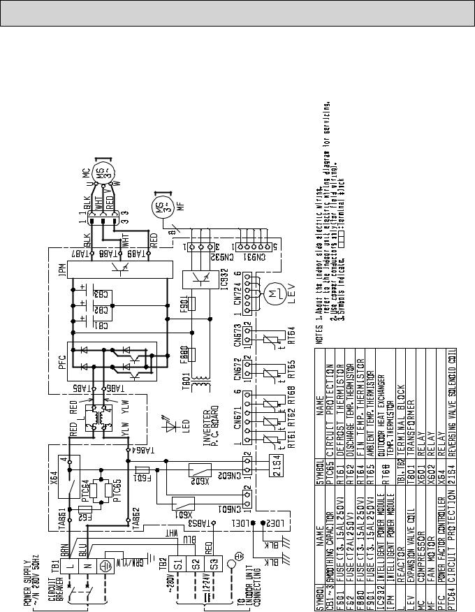
7 
 WIRING DIAGRAM
SUZ-KA25VA2.TH
SUZ-KA35VA2.TH
About the indoor side electric wiring, refer to |
the indoor unit electric wiring diagram for servicing. Use copper conductors only. (For field wiring) |
Symbols below indicate. |
: Terminal block |
NOTES:1. |
2. |
3. |
|
13

W |
RED 3 |
MS V WHT |
|
3~ |
BLK |
MC U |
1 |
14
|
|
|
|
|
|
|
|
ORN |
|
L61 |
YLW |
|
|
|
|
|
|
|
|
|
|
|
|
|
|
|
|
|
|
|
|
|
|
|
|
|
|
|
|
|
|
|
|
|
|
|
|
|
|
|
21S4 |
|
|
|
|
|
|
|
LD70 |
LD66 |
|
|
|
|
|
|
|
|
|
|
|
|
|
|
|
|
|
1 |
|
CN721 |
|
|
|
|
|
DB65 |
DB61 |
C63 |
C62 |
C61 |
|
|
|
|
|
|
|
|
|
|
|
|
|
X63 |
|
2 |
|
|
|
||
|
|
|
|
|
|
|
|
|
|
|
|
|
|
|
|
|
|
|
|
|
|
|
|||||
|
|
|
|
|
|
|
|
|
|
|
|
|
|
|
|
|
X64 |
|
|
|
|
|
|||||
|
|
|
|
|
|
IC802 |
|
|
|
|
|
|
|
|
|
|
|
|
|
|
|
||||||
|
|
|
|
|
|
|
|
|
|
|
|
|
|
|
|
|
|
|
|
|
|
|
|
||||
|
|
|
|
|
|
|
|
T801 |
|
|
|
|
|
|
|
|
|
F701 |
|
|
|
|
|
|
|
||
|
|
|
|
|
|
|
|
|
|
|
|
|
|
|
|
|
|
|
PTC64 |
|
|
|
|
||||
|
|
|
R825 |
|
|
|
F801 |
|
|
|
|
|
|
|
|
|
|
|
|
LD63 |
|
|
|
|
|||
|
|
|
|
|
|
|
|
|
|
|
|
|
|
|
|
|
|
|
|
|
|
|
LD-E1 |
|
|
|
|
3 |
RED |
TR821 |
R61 |
|
|
|
R937A |
|
R937B |
|
|
|
|
|
|
|
|
CT |
|
PTC65 |
BLK |
|
|
||||
|
|
|
|
|
|
|
|
|
|
|
|
|
|
|
|
|
|||||||||||
|
LDW |
W |
N |
|
|
|
|
|
|
|
|
|
|
|
|
|
|
|
|
|
|
|
|
|
TB1 |
|
|
|
WHT |
V |
|
|
|
F901 |
|
|
HC930 |
|
|
|
|
|
|
|
|
|
U |
|
|
|
|
GRN/YLW |
|
||
|
BLK |
LDV |
|
|
|
|
|
|
|
|
INVERTER P.C. BOARD |
|
|
|
DSA |
|
|
||||||||||
1 |
|
LDU |
U |
P |
|
|
|
|
|
|
|
|
|
L62 |
|
N |
|
||||||||||
|
|
|
|
|
|
|
|
|
|
|
|
|
|
|
|
|
|
|
|||||||||
|
|
IPM |
|
|
|
|
|
|
|
|
|
|
|
|
|
|
|
|
|
|
|
|
|
|
|||
|
|
|
|
|
|
|
|
|
|
|
|
|
|
|
|
|
|
|
|
|
|
|
|
L |
|
||
|
|
|
|
|
CN931 |
3 |
1 |
CN642 |
|
CN644 |
CN643 |
|
CN641 |
CN724 |
|
U |
|
U |
|
|
|
CIRCUIT |
|||||
|
|
|
|
|
|
|
|
|
|
LD-S |
BLU BRN |
|
BREAKER |
||||||||||||||
|
|
|
|
1 |
|
5 |
CN932 |
|
1 |
2 |
1 |
3 |
1 |
2 |
1 |
|
4 |
1 |
6 |
LD61 |
|
LD62 |
|
|
|||
|
|
|
|
|
|
|
|
|
|
|
|
||||||||||||||||
|
|
|
|
|
|
5 |
3 |
|
|
|
|
|
|
|
|
|
|
|
|
|
|
|
|
|
|
TB2 |
12-24V |
|
|
|
|
|
|
|
MS |
|
|
RT64 |
|
RT68 |
|
RT65 |
|
RT61 |
RT62 |
6 |
|
|
|
|
|
|
RED S3 |
||
|
|
|
|
|
|
|
|
|
|
|
|
M |
|
|
|
|
|
|
|
S2 |
|
||||||
|
|
|
|
|
|
|
|
|
|
|
|
|
|
|
|
|
|
|
|
|
|
|
|
|
|||
|
|
|
|
|
|
|
3~ |
|
|
|
|
|
|
|
|
|
|
|
|
|
|
|
|
BLU |
230V~ |
||
|
|
|
|
|
|
|
MF |
|
|
|
|
|
|
|
|
|
|
LEV |
|
BRN |
|
|
F61 |
|
BRN |
S1 |
|
|
|
|
|
|
|
|
|
|
|
|
|
|
|
|
|
|
|
|
|
|
|
|
|||||
TH.KA50VA2-SUZ
POWER SUPPLY |
~/N 230V 50Hz |
TO INDOOR |
UNIT CONNECTING |
SYMBOL |
NAME |
CT |
CURRENT TRANSFORMER |
C61,62,63 SMOOTHING CAPACITOR DB61,DB65 DIODE MODULE
DSA |
SURGE ABSORBER |
F61 |
FUSE (T20AL 250V) |
F701,F801,F901 |
FUSE (T3.15AL 250V) |
HC930,IPM |
INTELLIGENT POWER MODULE |
IC802 |
INTELLIGENT POWER DEVICE |
L61 |
REACTOR |
L62 |
REACTOR |
SYMBOL |
NAME |
SYMBOL |
NAME |
LEV |
EXPANSION VALVE COIL |
R61 |
CURRENT-DETECTING RESISTOR |
MC |
COMPRESSOR |
R825 |
CURRENT-DETECTING RESISTOR |
MF |
FAN MOTOR |
R937A, B CURRENT-DETECTING RESISTOR |
|
PTC64,PTC65 |
CIRCUIT PROTECTION |
TB1,TB52 TERMINAL BLOCK |
|
RT61 |
DEFROST THERMISTOR |
TR821 SWITCHING POWER TRANSISTOR |
|
RT62 |
DISCHARGE TEMP. THERMISTOR |
T801 |
TRANSFORMER |
RT64 |
FIN TEMP. THERMISTOR |
X63,X64 RELAY |
|
RT65 |
AMBIENT TEMP. THERMISTOR |
21S4 |
REVERSING VALVE COIL |
RT68 |
OUTDOOR HEAT EXCHANGER |
|
|
|
TEMP. THERMISTOR |
|
|
NOTES: 1. About the indoor side electric wiring, refer to the indoor unit electric wiring diagram for servicing.
2.Use copper conductors only (for field wiring).
3.Symbols below indicate.


 :Terminal block

TH.KA60VA2-SUZ
15
SYMBOL |
NAME |
SYMBOL |
NAME |
SYMBOL |
NAME |
NOTES: 1. About the indoor side electric wiring |
CB1~3 |
SMOOTHING CAPACITOR |
LEV |
EXPANSION VALVE |
RT65 |
AMBIENT TEMP. THERMISTOR |
refer to the indoor unit electric wiring |
CT1, 2 |
CURRENT TRANSFORMER |
MC |
COMPRESSOR |
RT68 |
OUTDOOR HEAT EXCHANGER TEMP. THERMISTOR |
diagram for servicing. |
CT61 |
CURRENT TRANSFORMER |
MF |
FAN MOTOR |
R64A,B RESISTOR |
2. Use copper conductors only (for field wiring). |
|
F64 |
FUSE (T2AL 250V) |
NF |
NOISE FILTER |
R937A, B RESISTOR |
3. Symbols below indicate. |
|
F801 |
FUSE (T3.15AL 250V) |
NR64 |
VARISTOR |
SSR61 SOLENOID COIL RELAY |
:Terminal block |
|
F911 |
FUSE (T1AL 250V) |
PFC |
POWER FACTOR CONTROLLER |
TB1 |
TERMINAL BLOCK |
|
HC930 INTELLIGENT POWER MODULE |
RS1~4 RESISTOR |
TB2 |
TERMINAL BLOCK |
|
||
HPS |
HIGH PRESSURE SWITCH |
RT61 |
DEFROST THERMISTOR |
T801 |
TRANSFORMER |
|
IPM |
INTELLIGENT POWER MODULE |
RT62 |
DISCHARGE TEMP. THERMISTOR |
X64 |
RELAY |
|
L |
REACTOR |
RT64 |
FIN TEMP. THERMISTOR |
21S4 |
REVERSING VALVE COIL |
|
SUZ-KA71VA2.TH
16

8 
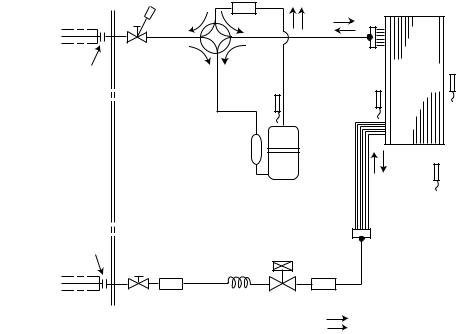
 REFRIGERANT SYSTEM DIAGRAM
SUZ-KA25VA2.TH |
Unit: mm |
Refrigerant pipe |
ø9.52 |
4-way valve |
|
|
|
|
(with heat insulator) |
|
|
|
|||
|
|
|
|
|
||
|
|
Muffler |
|
|
|
Outdoor heat |
|
|
|
|
|
|
|
|
|
Stop valve |
|
|
|
exchanger |
|
|
|
|
|
temperature |
|
|
|
(with service port) |
|
|
|
|
Flared connection |
Discharge |
Muffler |
Outdoor |
thermistor |
||
|
|
heat |
RT68 |
|||
|
|
|
temperature |
|
exchanger |
|
|
|
|
thermistor |
|
|
|
|
|
|
RT62 |
Compressor |
|
Ambient |
|
|
|
|
|
||
|
|
|
|
|
|
temperature |
|
|
|
|
|
|
thermistor |
|
|
|
|
Defrost |
|
RT65 |
|
|
|
|
|
|
|
|
|
|
|
thermistor |
|
|
|
|
|
|
RT61 |
|
|
|
|
|
|
|
Strainer |
|
Flared connection |
|
|
|
#100 |
|
|
Capillary tube |
LEV |
|
|
|
||
|
|
|
R.V. coil |
|||
|
|
ø3.0×ø2.0×240 |
|
|||
|
|
|
|
|
heating ON |
|
|
|
Stop valve |
|
|
cooling OFF |
|
|
|
|
|
|
|
|
Refrigerant pipe |
ø6.35 (with strainer) |
|
|
Refrigerant flow in cooling |
||
(with heat insulator) |
|
|
|
Refrigerant flow in heating |
||
Unit: mm
SUZ-KA35VA2.TH
Refrigerant pipe ø9.52 |
4-way valve |
|
|
|
|
(with heat insulator) |
|
|
|
||
|
|
|
|
|
|
|
Muffler |
|
|
|
Outdoor heat |
|
|
|
|
|
|
|
Stop valve |
|
|
|
exchanger |
|
|
|
|
temperature |
|
|
(with service port) |
|
|
|
|
Flared connection |
|
Muffler |
Outdoor |
thermistor |
|
Discharge |
|
heat |
RT68 |
||
|
temperature |
exchanger |
|
||
|
thermistor |
|
|
|
|
|
RT62 |
|
Compressor |
|
Ambient |
|
|
|
|
||
|
|
|
|
|
temperature |
|
|
|
|
|
thermistor |
|
|
|
Defrost |
|
RT65 |
|
|
|
|
|
|
|
|
|
thermistor |
|
|
|
|
|
RT61 |
|
|
|
|
|
Capillary tube |
|
|
|
|
|
ø3.0×ø1.8×600(×2) |
|
|
|
|
|
|
Strainer |
|
Flared connection |
|
LEV |
|
#100 |
|
Capillary tube |
|
|
|
||
|
|
R.V. coil |
|||
|
ø3.0×ø2.0×240 |
|
|
||
|
|
|
|
heating ON |
|
|
Stop valve |
|
|
cooling OFF |
|
|
|
|
|
|
|
Refrigerant pipe ø6.35 |
(with strainer) |
|
|
Refrigerant flow in cooling |
|
(with heat insulator) |
|
|
|
Refrigerant flow in heating |
|
17

SUZ-KA50VA2.TH |
|
|
|
|
|
|
|
|
Unit: mm |
|
|
Muffler |
|
|
4-way valve |
#100 |
|
|
|
Refrigerant pipe ø12.7 |
|
|
|
|
(with heat insulator) |
|
|
|
|
Stop valve |
|
|
|
|
(with service port) |
|
|
Outdoor |
|
Flared connection |
|
Discharge |
heat |
Ambient |
|
|
temperature |
exchanger |
temperature |
|
|
thermistor |
Defrost |
thermistor |
|
|
RT62 |
thermistor |
RT65 |
|
|
|
RT61 |
|
|
|
Compressor |
|
|
|
|
|
Outdoor heat |
|
|
|
|
exchanger |
|
|
|
|
temperature |
|
|
|
|
thermistor |
|
Flared connection |
|
|
RT68 |
|
|
LEV |
Strainer |
|
|
|
|
|
||
Receiver |
|
#100 |
|
|
Stop valve |
|
|
R.V. coil |
|
Capillary tube |
heating ON |
|||
(with strainer) |
ø3.6×ø2.4×50 |
cooling OFF |
||
Refrigerant pipe ø6.35 |
|
|
|
|
(with heat insulator) |
|
|
|
|
Refrigerant flow in cooling
 Refrigerant flow in heating
SUZ-KA60VA2.TH |
|
|
|
Unit: mm |
|
Refrigerant pipe :15.88 |
Muffler |
|
|
|
|
(with heat insulator) |
4-way valve #100 |
|
|
|
|
|
Stop valve |
High-pressure |
|
|
|
|
(with service port) |
Outdoor |
|
||
Flared connection |
Discharge |
switch |
|
||
heat |
Ambient |
||||
|
|||||
|
temperature |
Defrost |
exchanger |
temperature |
|
|
thermistor |
|
thermistor |
||
|
RT62 |
thermistor |
|
RT65 |
|
|
|
RT61 |
|
|
|
|
Compressor |
Outdoor heat |
|
|
|
|
|
|
|
|
|
|
exchanger |
|
|
|
|
temperature |
|
|
|
|
thermistor |
Flared connection |
|
|
|
RT68 |
Strainer |
LEV |
Strainer |
|
|
|
R.V. coil |
|||
Receiver #100 |
|
#100 |
||
|
|
|
|
heating ON |
Stop valve |
Capillary tube |
|
cooling OFF |
|
Refrigerant pipe :6.35 |
:3.6 :2.4 50 |
|
Refrigerant flow in cooling |
|
|
|
|
||
(with heat insulator) |
|
|
|
Refrigerant flow in heating |
18
|
|
SUZ-KA71VA2.TH |
Unit: mm |
Refrigerant pipe ø15.88 |
|
Muffler |
|
4-way valve |
#100 |
||
(with heat insulator) |
|||
|
|
Stop valve |
|
|
|
|
(with service port) |
|
|
Outdoor |
|
Flared connection |
Discharge |
|
heat |
Ambient |
|
temperature |
Defrost |
exchanger |
temperature |
|
thermistor |
|
thermistor |
|
|
RT62 |
thermistor |
|
RT65 |
|
|
RT61 |
|
|
|
Compressor |
Outdoor heat |
|
|
|
|
|
|
|
|
|
|
exchanger |
|
|
|
|
temperature |
|
|
|
|
thermistor |
|
Flared connection |
|
|
RT68 |
|
LEV |
Strainer |
|
|
|
Strainer |
R.V. coil |
|
||
#100 |
|
#100 |
|
|
|
|
|
heating ON |
|
Stop valve |
Capillary tube |
|
cooling OFF |
|
Refrigerant pipe ø9.52 |
ø4.0×ø2.4×100 |
Refrigerant flow in cooling |
||
|
||||
(with heat insulator) |
|
Refrigerant flow in heating |
||
19

SUZ-KA25VA2.TH SUZ-KA35VA2.TH SUZ-KA50VA2.TH
SUZ-KA60VA2.TH SUZ-KA71VA2.TH
MAX. REFRIGERANT PIPING LENGTH
Models |
Refrigerant piping: m |
Piping size O.D: mm |
|||
Max. Length A |
Max. Height difference B |
Gas |
Liquid |
||
|
|||||
SUZ-KA25VA2.TH |
20 |
12 |
9.52 |
|
|
SUZ-KA35VA2.TH |
6.35 |
||||
|
|
|
|||
SUZ-KA50VA2.TH |
30 |
30(15) |
12.7 |
||
|
|||||
SUZ-KA60VA2.TH |
15.88 |
|
|||
SUZ-KA71VA2.TH |
|
|
9.52 |
||
|
|
|
|||
( ): MFZ-KA50VA-E4
MAX. HEIGHT DIFFERENCE
Indoor |
unit |
+Max. Height difference B
Max. Length
A
Outdoor unit
+ Height difference limitations are binding regardless of which unit, indoor or outdoor, is position high.
ADDITIONAL REFRIGERANT CHARGE (R410A: g)
Models |
Outdoor unit |
|
|
|
|
|
Refrigerant piping length (one way) |
|
|
|
||||||
precharged |
5m |
|
6m |
7m |
|
8m |
|
9m |
10m |
11m |
12m |
13m |
14m |
15m |
20m |
|
|
|
|
|
|||||||||||||
SUZ-KA25VA2.TH |
800 |
0 |
|
0 |
0 |
|
90 |
|
120 |
150 |
180 |
210 |
240 |
270 |
300 |
450 |
SUZ-KA35VA2.TH |
1,050 |
0 |
|
0 |
0 |
|
90 |
|
120 |
150 |
180 |
210 |
240 |
270 |
300 |
450 |
|
|
|
|
|
|
|
|
|
Calculation: Xg=30g/mo(Refrigerant piping length(m)-5) |
|||||||
|
|
|
|
|
|
|
|
|
|
|
|
|
|
|||
Models |
Outdoor unit |
|
|
|
|
|
Refrigerant piping length (one way) |
|
|
|
||||||
precharged |
|
7m |
10m |
|
15m |
20m |
25m |
30m |
||||||||
|
|
|
||||||||||||||
SUZ-KA50VA2.TH |
1,600 |
|
0 |
60 |
|
|
160 |
260 |
360 |
460 |
||||||
SUZ-KA60VA2.TH |
1,800 |
|
0 |
60 |
|
|
160 |
260 |
360 |
460 |
||||||
|
|
|
|
|
|
|
|
Calculation : Xg=20g/m o (Refrigerant piping length(m)–7) |
||||||||
|
|
|
|
|
|
|
|
|
|
|
||||||
Models |
Outdoor unit |
|
|
|
|
|
Refrigerant piping length (one way) |
|
|
|
||||||
precharged |
|
7m |
10m |
|
15m |
20m |
25m |
30m |
||||||||
|
|
|
||||||||||||||
SUZ-KA71VA2.TH |
1,800 |
|
0 |
165 |
|
|
440 |
715 |
990 |
1,265 |
||||||
Calculation : Xg=55g/m o (Refrigerant piping length(m)-7)
20
9 
 ACTUATOR CONTROL
SUZ-KA25VA2.TH SUZ-KA35VA2.TH SUZ-KA50VA2.TH SUZ-KA60VA2.TH SUZ-KA71VA2.TH
9-1. Outdoor fan motor control
The fan motor turns ON/OFF, interlocking with the compressor.
[ON] The fan motor turns ON 5 seconds before the compressor starts up.
[OFF] The fan motor turns OFF 15 seconds after the compressor has stopped running.
5 seconds |
15 seconds |
ON
Compressor
OFF
ON
Outdoor fan
OFF
9-2. R.V. coil control
Heating . . . . . . . . . . . . . . . . . ON
Cooling . . . . . . . . . . . . . . . . . OFF Dry . . . . . . . . . . . . . . . . . . . . OFF
<COOL>
5 seconds
ON
Compressor OFF
R.V.coil ON
OFF
Outdoor fan ON motor OFF
NOTE: The 4-way valve reverses for 5 seconds right before start-up of the compressor.
<HEAT>
5 seconds
9-3. Relation between main sensor and actuator
Sensor |
Purpose |
|
|
Actuator |
|
|
Compressor |
LEV |
|
Outdoor fan |
R.V.coil |
||
|
|
|
motor |
|||
|
|
|
|
|
|
|
|
|
|
|
|
|
|
Discharge temperature |
Protection |
○ |
○ |
|
|
|
thermistor |
|
|
|
|||
|
|
|
|
|||
Indoor coil temperature |
Cooling: Coil frost prevention |
○ |
|
|
|
|
thermistor |
|
○ |
○ |
|
|
|
Heating: High pressure protection |
|
|
|
|
|
|
Defrost thermistor |
Heating: Defrosting |
○ |
○ |
|
○ |
○ |
|
|
|
|
|
||
Fin temperature thermistor |
Protection |
○ |
|
|
○ |
|
|
|
|
|
|
||
Ambient temperature |
Cooling: Low ambient temperature operation |
○ |
○ |
|
○ |
|
thermistor |
|
|
||||
Outdoor heat exchanger tem- |
Cooling: Low ambient temperature operation |
○ |
○ |
|
○ |
|
perature thermistor |
Cooling: High pressure protection |
○ |
○ |
|
○ |
|
|
|
|
|
|
||
|
|
|
|
|
|
|
21

10 
 SERVICE FUNCTIONS
SUZ-KA25VA2.TH SUZ-KA35VA2.TH
CHANGE IN DEFROST SETTING
<JS> When the JS wire of the outdoor Inverter P.C. board is cut/ soldered, the defrost finish temperature is changed. (Refer to 11-6-1)
|
Jumper wire |
Defrost finish temperature |
||
|
SUZ-KA25VA2.TH |
SUZ-KA35VA2.TH |
||
|
|
|
||
|
|
soldered |
5: |
10: |
JS |
|
(Initial setting) |
||
|
|
|
||
|
none |
8: |
13: |
|
|
|
|||
|
|
(cut) |
||
|
|
|
|
|
11 
 TROUBLESHOOTING
SUZ-KA25VA2.TH |
SUZ-KA35VA2.TH |
SUZ-KA71VA2.TH |
SUZ-KA50VA2.TH |
SUZ-KA60VA2.TH |
11-1. Cautions on troubleshooting
1.Before troubleshooting, check the following:
1)Check the power supply voltage.
2)Check the indoor/outdoor connecting wire for miswiring.
2.Take care the following during servicing.
1)Before servicing the air conditioner, be sure to turn OFF the main unit first with the remote controller, and turn off the breaker.
2)Be sure to turn OFF the power supply before removing the front panel, the cabinet, the top panel, and the electronic control P.C. board.
3)When removing the electrical parts, be careful of the residual voltage of smoothing capacitor.
4)When removing the electronic control P.C. board, hold the edge of the board with care NOT to apply stress on the components.
5)When connecting or disconnecting the connectors, hold the housing of the connector. DO NOT pull the lead wires.
|
|
|
|
|
|
|
|
|
|
|
|
|
|
|
Lead wire |
Housing point |
|||
3.Troubleshooting procedure
1)First, check if the OPERATION INDICATOR lamp is blinking on and off to indicate an abnormality. To make sure, check how many times the abnormality indication is blinking on and off before starting service work.
2)Before servicing check that the connector and terminal are connected properly.
3)If the electronic control P.C. board is supposed to be defective, check the copper foil pattern for disconnection and the components for bursting and discoloration.
4)When troubleshooting, refer to 11-2. and 11-3.
22

11-2. Failure mode recall function
As this air conditioner has a function to memorize all the failures that had happened, the latest failure detail can be recalled by following the procedures below.
Use this function when the check code is not displayed with wired remote controller or the remote controller at use is wireless type.
11-2-1. Flow chart of the indoor/outdoor unit failure mode recall function
Operational procedure (For wireless remote controller)
Setting up the failure mode recall function
Turn ON the power supply.
While pressing both OPERATION SELECT button and TOO COOL button on the remote controller at the same time, press RESET button.
First, release RESET button.
And release the other two buttons since all LCD in operation display section of the remote controller is displayed after 3 seconds.
TOO |
TOO |
COOL |
|
|
FAN |
SELECT |
|
|
|
|
|
L |
|
TIME |
AUTO COO |
VANE |
||
HEAT |
DRY |
|
|
|
|
||
|
|
|
RESET |
While pressing both OPERATION SELECT button and TOO COOL button on the
remote controller at the same time, press RESET button.
First, release RESET button.
And release the other two buttons since all LCD
in operation display section of the remote controller is displayed after 3 seconds.
1
Press OPERATE/STOP (ON/OFF) button of the remote controller (the set temperature is displayed).


 h
h
ON/OFF |
TOO |
TOO |
|
WARM |
COOL |
1. Regardless of normal or abnormal, a short beep is emitted once as the signal is received.
Does OPERATION INDICATOR lamp on the indoor unit blink at the interval of 0.5 seconds?
Blinks: Either indoor or outdoor unit is abnormal. Beep sounds are emitted at the same timing of the blinking of OPERATION INDICATOR lamp. 2
Yes Judgment of indoor/outdoor abnormality (Blinks)
No (OFF)
Indoor unit is normal.
There is a possibility that the plasma or outdoor unit is abnormal.  Confirm the failure detail on the LED display of the outdoor
controller board.(refer to 11-2-4.)
Before blinking, does POWER |
Yes |
||
lamp stay ON for 3 seconds? |
|||
|
|||
Stays ON for 3 seconds (without beep): |
|
||
The outdoor unit is abnormal. |
|
||
|
No |
|
|
|
|
||
The indoor unit is abnormal.
Check the blinking pattern, and confirm the abnormal point.
Make sure to check at least two consecutive blinking cycles. 2
The outdoor unit is abnormal.
Check the blinking pattern, and confirm the abnormal point(11-2.3.).
Make sure to check at least two consecutive blinking cycles. 3
Releasing the failure mode recall function |
|
Release the failure mode recall function by the following procedures. |
|
With the remote controller headed towards the indoor unit, press any button |
|
that is not used in this failure mode recall function (e.g. TIMER button) . |
|
OR |
|
Turn OFF the power supply and turn ON it again. |
|
Press RESET button of the remote controller. |
OPERATION INDICATOR lamp |
|
Repair the defective parts.
Note1. Make sure to release the failure mode recall function once it is set up, otherwise the unit cannot operate properly. 2. If the abnormal condition is not deleted from the memory, the last abnormal condition is kept memorized.
2. Blinking pattern when the indoor unit is abnormal:[Output pattern A]
Beeper sounds |
Beep |
|
Beep |
Beep |
Beep |
|||||||
OPERATION |
|
|
|
|
|
|
1st |
|
2nd |
|
3rd |
|
INDICATOR |
|
|
|
|
|
|
|
|
|
|
|
|
lamp blink |
|
|
|
Off |
|
|
On |
On |
On |
|||
pattern |
Self-check Approx. 2.5 sec.0.5 sec. 0.5 sec. 0.5 sec. |
|||||||||||
starts (Start signal received)
Beep |
|
|
Beep |
Beep |
||||||
|
|
|
|
|
|
|
|
|
|
|
|
n th |
|
|
|
|
|
1st |
|
2 nd · · · Repeated |
|
|
|
|
|
|
|
|
|
|||
|
On |
Off |
|
|
On |
On |
||||
0.5 sec. Approx. 2.5 sec.0.5 sec. |
0.5 sec. |
|||||||||
Number of blinks/beeps in pattern indicates the check code in the next page
3.Blinking pattern when the outdoor unit is abnormal:[Output pattern B]
Beeper sounds |
Beep |
OPERATION |
|
INDICATOR |
|
lamp blink |
Off |
pattern |
Self-check Approx. 2.5 sec. |
|
starts |
|
(Start signal |
|
received) |
|
|
|
Beep |
Beep |
Beep |
|
Beep |
|
|
|
|
|
Beep |
Beep |
||||||||||
|
|
|
|
|
|
|
|
|
|
|
|
|
|
|
|
|
|
|
|
|
|
|
|
|
|
|
|
|
1st |
|
2nd |
|
3rd |
|
|
|
nth |
|
|
|
|
|
|
|
|
1st |
|
2nd · · · Repeated |
|
|
|
|
On |
On |
On |
|
|
|
|
|
|
|
|
|
On |
On |
||||||||
On |
|
|
|
On |
Off |
|
On |
|
||||||||||||||||
Approx. 3 sec. |
0.5 sec. 0.5 sec.0.5 sec. |
|
0.5 sec. Approx. 2.5 sec. |
|
Approx. 3 sec. |
0.5 sec. |
0.5 sec. |
|||||||||||||||||
Number of blinks/beeps in pattern indicates the check |
|
|
Number of blinks/beeps in pattern indicates |
|||||||||||||||||||||
code in the next page (i.e., n=5 for “U2”) |
|
|
|
|
|
the check code in the next page |
||||||||||||||||||
23
 Loading...