


Air Conditioners
Indoor unit
Кондиционеры
ВНУТРЕННИЙ БЛОК
SLZ-M15, M25, M35, M50, M60FA
OPERATION MANUAL |
|
FOR USER |
For safe and correct use, please read this operation manual thoroughly before operating the air-conditioner unit.
BEDIENUNGSHANDBUCH |
|
FÜR BENUTZER |
Zum sicheren und einwandfreien Gebrauch der Klimaanlage dieses Bedienungshandbuch vor Inbetriebnahme gründlich durchlesen.
MANUEL D’UTILISATION |
|
POUR L’UTILISATEUR |
Pour une utilisation correcte sans risques, veuillez lire le manuel d’utilisation en entier avant de vous servir du climatiseur.
BEDIENINGSHANDLEIDING |
|
VOOR DE GEBRUIKER |
Voor een veilig en juist gebruik moet u deze bedieningshandleiding grondig doorlezen voordat u de airconditioner gebruikt.
MANUAL DE INSTRUCCIONES |
|
PARA EL USUARIO |
Lea este manual de instrucciones hasta el final antes de poner en marcha la unidad de aire acondicionado para garantizar un uso seguro y correcto.
ISTRUZIONI DI FUNZIONAMENTO |
|
PER L’UTENTE |
Leggere attentamente questi istruzioni di funzionamento prima di avviare l’unità, per un uso corretto e sicuro della stessa.
ΕΓΧΕΙΡΙΔΙΟ ΟΔΗΓΙΩΝ ΧΡΗΣΕΩΣ |
|
ΓΙΑ ΤΟΝ ΧΡΗΣΤΗ |
Για ασφάλεια και σωστή χρήση, παρακαλείστε διαβάσετε προσεχτικά αυτό το εγχειρίδιο χρήσεως πριν θέσετε σε λειτουργία τη μονάδα κλιματισμού.
MANUAL DE OPERAÇÃO |
|
PARA O UTILIZADOR |
Para segurança e utilização correctas, leia atentamente o manual de operação antes de pôr a funcionar a unidade de ar condicionado.
DRIFTSMANUAL |
|
TIL BRUGER |
Læs venligst denne driftsmanual grundigt før airconditionanlægget betjenes af hensyn til sikker og korrekt brug.
DRIFTSMANUAL |
|
FÖR ANVÄNDAREN |
Läs denna driftsmanual noga för säkert och korrekt bruk innan luftkonditioneringen används.
IŞLETME ELKITABI |
|
KULLANICI İÇİN |
Emniyetli ve doğru biçimde nasıl kullanılacağını öğrenmek için lütfen klima cihazını işletmeden önce bu elkitabını dikkatle okuyunuz.
РУКОВОДСТВО ПО ЭКСПЛУАТАЦИИ ДЛЯ ПОЛЬЗОВАТЕЛЯ
Для обеспечения правильного и безопасного использования следует ознакомиться с инструкциями, указанными в данном руководстве по эксплуатации, тщательным образом до того, как приступать к использованию кондиционера.
BRUKSANVISNING |
|
FOR BRUKER |
Vennligst les nøye gjennom denne bruksanvisningen, for sikkert og riktig bruk av klimaanlegget.
INSTRUKCJA OBSŁUGI |
|
INFORMACJA DLA UŻYTKOWNIKA |
Aby zapewnić bezpieczne i prawidłowe korzystanie z urządzenia, należy wcześniej uważnie przeczytać niniejszą instrukcję obsługi.
English
Deutsch
Français
Nederlands
Español
Italiano
ελληνικά
Português
Dansk
Svenska
Türkçe
Русский
Norsk
Polski
Contents
1. |
Safety Precautions |
.............................................................................. 2 |
6. |
Emergency Operation for Wireless Remote-controller...................... |
15 |
2. |
Parts Names....................................................................................... |
3 |
7. Trouble Shooting............................................................................... |
15 |
|
3. |
Operation ........................................................................................... |
6 |
8. |
Installation, relocation and inspection............................................... |
16 |
4. Timer................................................................................................. |
13 |
9. |
Specifications.................................................................................... |
17 |
|
5. |
Care and Cleaning............................................................................ |
14 |
|
|
|
Note
Fig. 1
This symbol mark is for EU countries only.
This symbol mark is according to the directive 2012/19/EU Article 14 Information for users and Annex IX, and/or to the directive 2006/66/EC Article 20 Information for end-users and Annex II.
Your MITSUBISHI ELECTRIC product is designed and manufactured with high quality materials and components which can be recycled and/or reused. This symbol means that electrical and electronic equipment, batteries and accumulators, at their end-of-life, should be disposed of separately from your household waste. If a chemical symbol is printed beneath the symbol (Fig. 1), this chemical symbol means that the battery or accumulator contains a heavy metal at a certain concentration.
This will be indicated as follows: Hg: mercury (0.0005%), Cd: cadmium (0.002%), Pb: lead (0.004%)
In the European Union there are separate collection systems for used electrical and electronic products, batteries and accumulators. Please, dispose of this equipment, batteries and accumulators correctly at your local community waste collection/recycling centre. Please, help us to conserve the environment we live in!
Note:
The phrase “Wired remote controller” in this operation manual refers only to the PAR-33MAA. If you need any information for the other remote controller, please refer to the instruction book included in this box.
1. Safety Precautions
►Before installing the unit, make sure you read all the “Safety Precautions”.
►The “Safety Precautions” provide very important points regarding safety. Make sure you follow them.
►Please report to or take consent by the supply authority before connection to the system.
Symbols used in the text
 Warning:
Describes precautions that should be observed to prevent danger of injury or death to the user.
 Caution:
Describes precautions that should be observed to prevent damage to the unit.
Symbols used in the illustrations
 : Indicates a part which must be grounded.
MEANINGS OF SYMBOLS DISPLAYED ON THE UNIT
|
|
WARNING |
This mark is for R32 refrigerant only. Refrigerant type is written on nameplate of outdoor unit. |
|
|
In case that refrigerant type is R32, this unit uses a flammable refrigerant. |
|
|
|
(Risk of fire) |
If refrigerant leaks and comes in contact with fire or heating part, it will create harmful gas and there is risk of fire. |
|
|
|
|
|
|
|
|
Read the OPERATION MANUAL carefully before operation.
Service personnel are required to carefully read the OPERATION MANUAL and INSTALLATION MANUAL before operation.
Further information is available in the OPERATION MANUAL, INSTALLATION MANUAL, and the like.
 Warning:
•There appliances are not accessible to the general public.
•The unit must not be installed by the user. Ask the dealer or an authorized company to install the unit. If the unit is installed improperly, water leakage, electric shock or fire may result.
•Do not stand on, or place any items on the unit.
•Do not splash water over the unit and do not touch the unit with wet hands.
An electric shock may result.
•Do not spray combustible gas close to the unit. Fire may result.
•Do not place a gas heater or any other open-flame appliance where it will be exposed to the air discharged from the unit. Incomplete combustion may result.
•Do not remove the front panel or the fan guard from the outdoor unit when it is running.
•When you notice exceptionally abnormal noise or vibration, stop operation, turn off the power switch, and contact your dealer.
•Never insert fingers, sticks etc. into the intakes or outlets.
•If you detect odd smells, stop using the unit, turn off the power switch and consult your dealer. Otherwise, a breakdown, electric shock or fire may result.
•This air conditioner is NOT intended for use by children or infirm persons without supervision.
•Young children must be supervised to ensure that they do not play with the air conditioner.
•If the refrigeration gas blows out or leaks, stop the operation of the air conditioner, thoroughly ventilate the room, and contact your dealer.
•This appliance is intended to be used by expert or trained users in shops, in light industry and on farms, or for commercial use by lay persons.
•This appliance can be used by children aged from 8 years and above and persons with reduced physical, sensory or mental capabilities or lack of experience and knowledge if they have been given supervision or instruction concerning use of the appliance in a safe way and understand the hazards involved. Children shall not play with the appliance. Cleaning and user maintenance shall not be made by children without supervision.
•This appliance is not intended for use by persons (including children) with reduced physical, sensory or mental capabilities, or lack of experience and knowledge, unless they have been given supervision or instruction concerning use of the appliance by a person responsible for their safety.
•Children should be supervised to ensure that they do not play with the appliances.
•When installing or relocating, or servicing the air conditioner, use only the specified refrigerant written on outdoor unit to charge the refrigerant lines.
Do not mix it with any other refrigerant and do not allow air to remain in the lines.
If air is mixed with the refrigerant, then it can be the cause of abnormal high pressure in the refrigerant line, and may result in an explosion and other hazards.
The use of any refrigerant other than that specified for the system will cause mechanical failure or system malfunction or unit breakdown. In the worst case, this could lead to a serious impediment to securing product safety.
•This unit should be installed in rooms which exceed the floor space specified in outdoor unit installation manual.
Refer to outdoor unit installation manual.
•Do not use means to accelerate the defrosting process or to clean, other than those recommended by the manufacturer.
•The appliance shall be stored in a room without continuously operating ignition sources (for example: open flames, an operating gas appliance or an operating electric heater).
•Do not pierce or burn.
•Be aware that refrigerants may not contain an odour.
2
1. Safety Precautions
 Caution:
•Do not use any sharp object to push the buttons, as this may damage the remote controller.
•Never block or cover the indoor or outdoor unit’s intakes or outlets.
Disposing of the unit
When you need to dispose of the unit, consult your dealer.
2. Parts Names
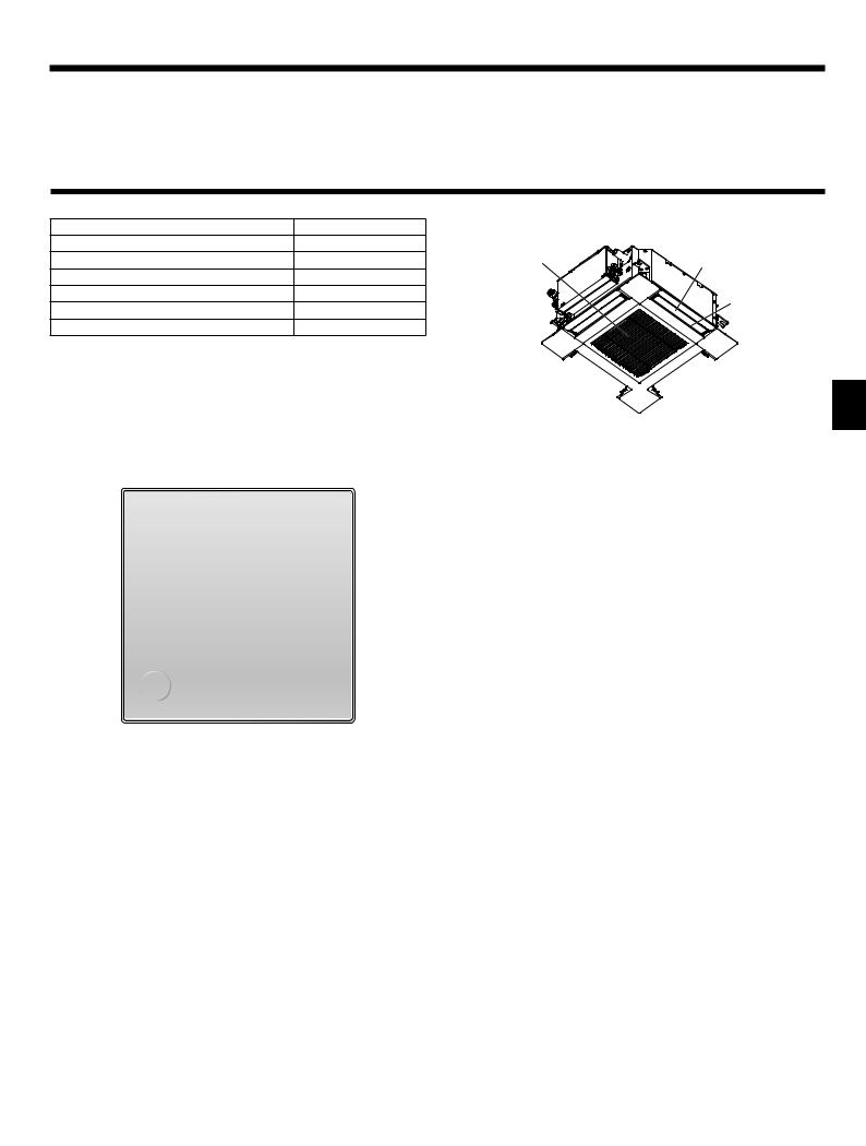
■ Indoor Unit |
|
■ SLZ-M·FA |
|
|
SLZ-M·FA |
4-way Ceiling Cassette |
|
|
|
|
|
Fan steps |
3 steps |
|
|
Vane |
Auto with swing |
Filter |
Vane |
Louver |
– |
|
|
|
|
||
Filter |
Long-life |
|
Air outlet |
Filter cleaning indication |
2,500 hr |
|
|
|
|
||
Wireless remote controller model No. setting |
002 |
|
|
Air intake 


■ Wired Remote Controller
Controller interface
The functions of the function buttons change depending on the screen.
Refer to the button function guide that appears at the bottom of the LCD for the functions they serve on a given screen.
When the system is centrally controlled, the button function guide
5that corresponds to the locked button will not appear.
Main display |
Main menu |
Fri |
Main Main menu |
|
|
|
|
|
|
|
Vane·Louver·Vent. (Lossnay) |
|||
|
|
|
|
Room |
|
|
High power |
|
|
|
|
|
|
|
|
|
Timer |
|
|
|
|
|
|
|
Cool |
Set temp. |
|
Weekly timer |
|
|
||
|
|
|
6 |
|
|
|
OU silent mode |
|
|
|
|
|
|
|
|
|
Main display: |
|
|
||
|
|
|
|
|
|
|
|
|
||
|
|
|
Mode |
Temp. |
Fan |
Cursor |
Page |
|
||
|
|
|
7 |
8 |
9 |
0 |
7 |
8 |
9 |
0 |
|
|
|
|
|
|
Function guide |
|
|
|
|
4 |
3 |
2 |
1 |
|
|
|
|
|
|
|
Function buttons |
|
|
|
|
|
|
|
|
|
|
7 |
8 |
9 |
0 |
|
|
|
|
|
|
|
▌1 [ON/OFF] button
Press to turn ON/OFF the indoor unit.
▌2 [SELECT] button
Press to save the setting.
▌3 [RETURN] button
Press to return to the previous screen.
▌4 [MENU] button
Press to bring up the Main menu.
▌5 Backlit LCD
Operation settings will appear.
When the backlight is off, pressing any button turns the backlight on and it will stay lit for a certain period of time depending on the screen.
When the backlight is off, pressing any button turns the backlight on and does not perform its function. (except for the [ON/OFF] button)
▌6 ON/OFF lamp
This lamp lights up in green while the unit is in operation. It blinks while the remote controller is starting up or when there is an error.
▌7 Function button [F1]
Main display: Press to change the operation mode.
Main menu: Press to move the cursor down.
▌8 Function button [F2]
Main display: Press to decrease temperature.
Main menu: Press to move the cursor up.
▌9 Function button [F3]
Main display: Press to increase temperature.
Main menu: Press to go to the previous page.
▌0 Function button [F4]
Main display: Press to change the fan speed.
Main menu: Press to go to the next page.
3
2. Parts Names
Display
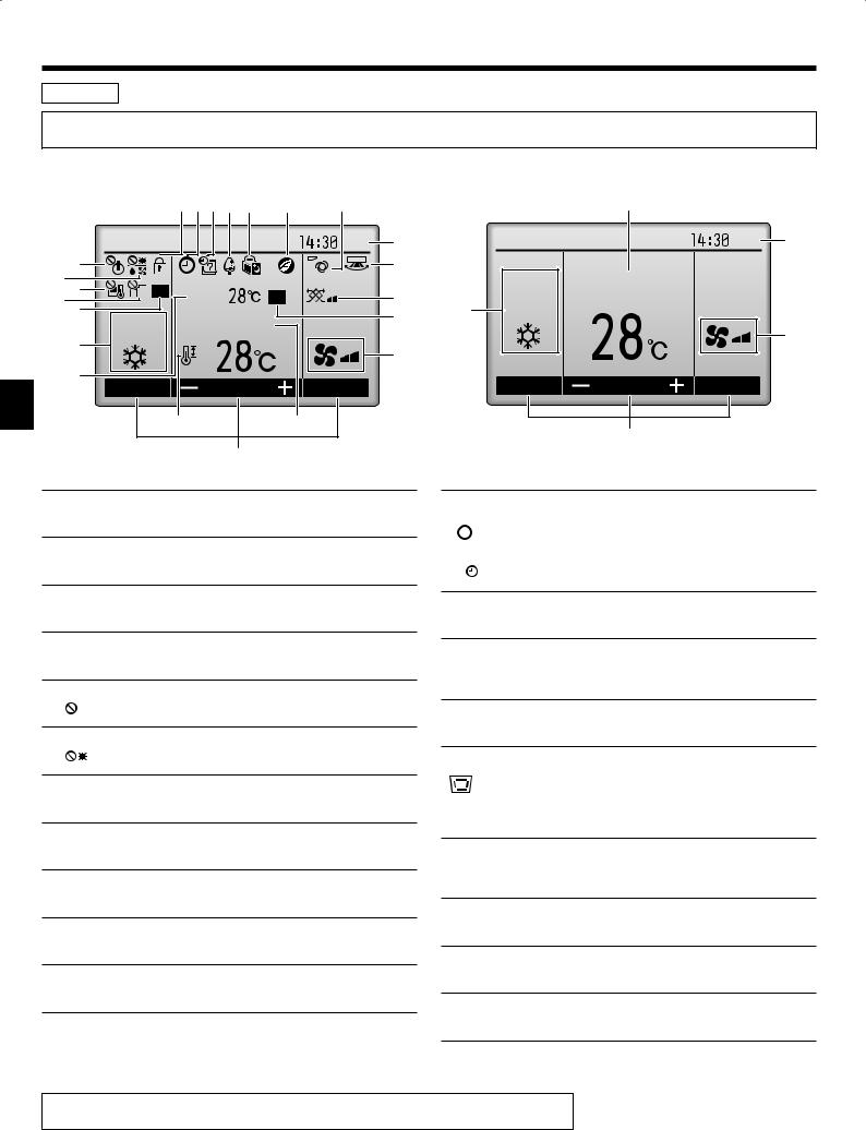
The main display can be displayed in two different modes: “Full” and “Basic”. The factory setting is “Full”. To switch to the “Basic” mode, change the setting on the Main display setting. (Refer to operation manual included with remote controller.)
<Full mode> |
|
|
|
|
* All icons are displayed for explanation. |
|
|
|
|
2 3 4 5 6 |
8 |
9 |
|
|
|
|
|
Fri |
3 |
6 |
|
|
|
) |
7 |
|
|
|
|
8 |
Room |
|
|
! |
9 0 |
|
|
||
Cool |
Set temp. |
|
|
7 |
|
|
|
||
1 |
|
|
|
|
|
|
|
|
4 |
1 |
Temp. |
|
Fan |
|
Mode |
|
|
||
@ |
|
2 |
|
|
5
▌1 Operation mode
Indoor unit operation mode appears here.
▌2 Preset temperature
Preset temperature appears here.
▌3 Clock (See the Installation Manual.)
Current time appears here.
▌4 Fan speed
Fan speed setting appears here.
▌5 Button function guide
Functions of the corresponding buttons appear here.
▌6 
Appears when the ON/OFF operation is centrally controlled.
▌7 
Appears when the operation mode is centrally controlled.
▌8 
Appears when the preset temperature is centrally controlled.
▌9 
Appears when the filter reset function is centrally controlled.
▌0
Indicates when filter needs maintenance.
▌1 Room temperature (See the Installation Manual.)
Current room temperature appears here.
▌2
Appears when the buttons are locked.
<Basic mode>
2
Fri |
3 |
Cool |
Set temp. |
1
4
Mode |
Temp. |
Fan |
5
▌3
Appears when the On/Off timer, Night setback, or Auto-off timer function is enabled.
 appears when the timer is disabled by the centralized control system.
▌4 
Appears when the Weekly timer is enabled.
▌5
Appears while the units are operated in the energy-save mode. (Will not appear on some models of indoor units)
▌6
Appears while the outdoor units are operated in the silent mode.
▌7
Appears when the built-in thermistor on the remote controller is activated to monitor the room temperature (1).
appears when the thermistor on the indoor unit is activated to monitor the room temperature.
▌8
Appears when the units are operated in the energy-save mode with 3D i-see Sensor.
▌9
Indicates the vane setting.
▌)
Indicates the louver setting.
▌!
Indicates the ventilation setting.
▌@
Appears when the preset temperature range is restricted.
Most settings (except ON/OFF, mode, fan speed, temperature) can be made from the Menu screen. (Refer to operation manual included with remote controller.)
4

2. Parts Names
■Wireless Remote-Controller
Transmission area
Not available
Remote controller display
Battery replacement indicator
Set Temperature buttons |
|
|
OFF/ON button |
Mode button (Changes operation mode) |
Fan Speed button (Changes fan speed) |
|
|
Airfl ow button (Changes up/down airfl ow direction) |
i-see button |
|
|
Timer ON button |
Menu button |
|
|
Timer OFF button |
SET/SEND button |
|
|
Weekly timer ON/OFF button |
CANCEL button |
|
|
|
Up/Down buttons |
Set Time button (Sets the time) |
Reset button |
Operation mode |
|
Not available |
|
Cool |
Dry |
Appears when a non-supported func- |
|
Fan |
Auto |
tion is selected. |
|
|
|||
(single set point) |
|
||
|
|
||
Heat |
Auto* |
|
|
(dual set point) |
Battery replacement indicator |
||
|
|||
|
|
||
* The initial setting is necessary. |
Appears when the remaining battery |
||
Refer to Installation manual. |
power is low. |
||
Temperature setting
The units of temperature can be changed. For details, refer to the Installation Manual.
Vane setting
Step 1 Step 2 Step 3 Step 4 Step 5 Swing Auto
Fan speed setting
3D i-see sensor (Air distribution)
Default |
Direct |
Indirect When Direct or Indirect |
|
|
is selected, the vane |
|
|
setting is set to “Auto”. |
5

2. Parts Names
Notes (Only for wireless remote controller):
■When using the wireless remote controller, point it towards the receiver on the indoor unit.
■If the remote controller is operated within approximately 2 minutes after power is supplied to the indoor unit, the indoor unit may beep twice as the unit is performing the initial automatic check.
■The indoor unit beeps to confirm that the signal transmitted from the remote controller has been received. Signals can be received up to approximately 7 meters in a direct line from the indoor unit in an area 45° to the left and right of the unit. However, illumination such as fluorescent lights and strong light can affect the ability of the indoor unit to receive signals.
■If the operation lamp near the receiver on the indoor unit is blinking, the unit needs to be inspected.
Consult your dealer for service.
■Handle the remote controller carefully! Do not drop the remote controller or subject it to strong shocks. In addition, do not get the remote controller wet or leave it in a location with high humidity.
■To avoid misplacing the remote controller, install the holder included with the remote controller on a wall and be sure to always place the remote controller in the holder after use.
■If the indoor unit beeps 4 times when you are using the wireless remote controller, switch the auto mode setting to the AUTO (single set point) mode or AUTO (dual set point) mode.
For details, refer to the included Notice (A5 sheet) or the Installation Manual.
■Outdoor unit
Power
Ref. Pipes
Indoor-Outdoor
 Connection wire
Earth
Battery installation/replacement
1.Remove the top cover, insert two LR6 AA batteries, and then install the top cover.
1


 2
2
Top cover |
3 |
|
Two LR6 AA batteries
Insert the negative (–) end of each battery first. Install the batteries in the correct directions (+, –)!
2. Press the Reset button.
Press the Reset button with an object that has a narrow end.
3. Operation
■About the operation method, refer to the operation manual that comes with each remote controller.
3.1. Turning ON/OFF |
|
[ON] |
[OFF] |
Press the [ON/OFF] button.
The ON/OFF lamp will light up in green, and the operation will start.
Press the [ON/OFF] button again. The ON/OFF lamp will come off, and the operation will stop.
Note:
Even if you press the ON/OFF button immediately after shutting down the operation is progress, the air conditioner will not start for about 3 minutes.
This is to prevent the internal components from being damaged.
6
3. Operation
■Operation status memory
|
Remote controller setting |
|
|
|
|
Operation mode |
Operation mode before the power was turned off |
|
|
|
|
Preset temperature |
Preset temperature before the power was turned off |
|
|
|
|
Fan speed |
Fan speed before the power was turned off |
|
|
|
|
■ Settable preset temperature range |
||
|
|
|
Operation mode |
Preset temperature range |
|
|
|
|
Cool/Dry |
19 – 30 ºC |
|
|
|
|
Heat |
17 – 28 ºC |
|
|
|
|
Auto |
19 – 28 ºC |
|
|
|
|
Fan/Ventilation |
Not settable |
|
|
|
|
3.2. Mode Selection
|
|
|
|
Fri |
|
|
Room |
|
|
Cool |
|
Set temp. |
|
|
Mode |
|
Temp. |
|
Fan |
|
|
F1 F2 F3 F4
Press the [F1] button to go through the operation modes in the order of “Cool”, “Dry”, “Fan”, “Auto”, and “Heat”. Select the
desired operation mode.
Cool |
|
Dry |
|
Fan |
Auto |
|
Heat |
|
|
|
|
|
||
|
|
|
||
|
|
|
|
|
•Operation modes that are not available to the connected indoor unit models will not appear on the display.
What the blinking mode icon means
The mode icon will blink when other indoor units in the same refrigerant system (connected to the same outdoor unit) are already operated in a different mode. In this case, the rest of the unit in the same group can only be operated in the same mode.
Information for multi system air conditioner (Outdoor unit: MXZ series)
►Multi system air conditioner (Outdoor unit: MXZ series) can connect two or more indoor units with one outdoor unit. According to the capacity, 2 or more units can operate simultaneously.
•When you try to operate 2 or more indoor units with 1 outdoor unit simultaneously, one for the cooling and the other for heating, the operation mode of the indoor unit that operates earlier is selected. The other indoor units that will start the operation later cannot operate, indicating an operation state in blinking.
In this case, please set all the indoor units to the same operation mode.
•There might be a case that the indoor unit, which is operating in “Auto” mode. Cannot change over to the operating mode “Cool”/“Heat” and becomes a state of standby.
•When indoor unit starts the operation while the defrosting of outdoor unit is being done, it takes a few minutes (max. about 15 minutes) to blow out the warm air.
•In the heating operation, though indoor unit that does not operate may get warm or the sound of refrigerant flowing may be heard, they are not malfunction. The reason is that the refrigerant continuously flows into it.
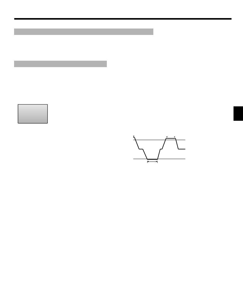
Automatic operation
■According to a set temperature, cooling operation starts if the room temperature is too hot and heating operation starts if the room temperature is too cold.
■During automatic operation, if the room temperature changes and remains 2 °C or more above the set temperature for 15 minutes, the air conditioner switches to cooling mode. In the same way, if the room temperature remains 2 °C or more below the set temperature for 15 minutes, the air conditioner switches to heating mode.
Cooling mode |
15 minutes (switches from |
||||||||
|
|
|
heating to cooling) |
||||||
|
|
|
|||||||
|
|
|
|
|
|
|
|
|
Set temperature +2 °C |
|
|
|
|
|
|
|
|
|
|
|
|
|
|
|
|
|
|
|
Set temperature |
|
|
|
|
|
|
|
|
|
|
Set temperature -2 °C
15 minutes (switches from cooling to heating)
3.3. Temperature setting
<Cool, Dry, Heat, and Auto>
|
|
|
|
Fri |
|
|
|
|
|
Fri |
|
|
|
Room |
|
|
|
|
|
Room28.5 |
|
|
|
Cool |
|
Set temp. |
|
|
Cool |
|
Set temp. |
|
|
|
|
Mode |
|
Temp. |
|
Fan |
|
|
|
28.5 |
|
|
|
|
|
|
Mode |
|
Temp. |
|
Fan |
||||
|
|
|
|
|
|
|
Example display |
|
|
||
F1 |
|
F2 |
F3 |
F4 |
(Centigrade in 0.5-degree increments) |
||||||
|
|
|
|
|
|
|
|
||||
Press the [F2] button to decrease the preset temperature, and press the [F3] button to increase.
•Refer to the table on page 7 for the settable temperature range for different operation modes.
•Preset temperature range cannot be set for Fan/Ventilation operation.
•Preset temperature will be displayed either in Centigrade in 0.5- or
1-degree increments, or in Fahrenheit, depending on the indoor unit model and the display mode setting on the remote controller.
7
3. Operation
3.4. Fan speed setting
|
|
|
|
Fri |
|
|
Room |
|
|
Cool |
|
Set temp. |
|
|
Mode |
|
Temp. |
|
Fan |
|
|
F1 F2 F3 F4
Press the [F4] button to go through the fan speeds in the following order.
Auto
•The available fan speeds depend on the models of connected indoor units.
Notes:
●The number of available fan speeds depends on the type of unit connected.
●In the following cases, the actual fan speed generated by the unit will differ from the speed shown the remote controller display. 1.While the display is in “STAND BY” or “DEFROST” states. 2.When the temperature of the heat exchanger is low in the heat-
ing mode.
(e.g. immediately after heating operation starts)
3.In HEAT mode, when room temperature is higher than the temperature setting.
4.When the unit is in DRY mode.
3.5. Airflow direction setting
3.5.1 Navigating through the Main menu
<Accessing the Main menu>
Main |
Main menu |
|
Press the [MENU] button. |
Vane·Louver·Vent. (Lossnay) |
The Main menu will appear. |
||
High power |
|
|
|
Timer |
|
|
|
Weekly timer |
|
|
|
OU silent mode |
|
|
|
Main display: |
|
|
|
|
Cursor |
Page |
|
F1 F2 F3 F4
<Item selection>
Main |
Main menu |
Vane·Louver·Vent. (Lossnay)
High power
Cursor  Timer
Timer
Weekly timer
OU silent mode
Main display:
Cursor |
Page |
Press [F1] to move the cursor down. Press [F2] to move the cursor up.
F1 F2 F3 F4
<Navigating through the pages>
|
|
|
Main |
|
Main menu |
|
|
|
page |
||
|
|
|
|
|
|
||||||
|
|
|
|
Vane·Louver·Vent. (Lossnay) |
|
|
|||||
|
|
|
|
High power |
|
|
|
|
|
||
|
|
|
|
Timer |
|
|
|
|
Press [F3] to go to the previous page. |
||
|
|
|
|
Weekly timer |
|
|
|
|
|||
|
|
|
|
OU silent mode |
|
|
|
Press [F4] to go to the next page. |
|||
|
|
|
Main display: |
|
|
|
|
|
|||
|
|
|
|
|
Cursor |
Page |
|
|
|
|
|
|
|
|
F1 |
|
F2 |
F3 |
F4 |
|
|
||
|
|
|
|
|
|
|
|
|
|||
|
|
|
|
|
|
|
|
|
|||
|
|
|
|
|
|
|
|
|
|
|
|
|
|
|
|
|
|
|
|
|
|||
<Saving the settings> |
|
|
|
|
|||||||
|
|
|
|
|
|
OU silent mode |
|
|
|
Select the desired item, and press |
|
|
|
|
|
Mon |
Tue Wed Thu Fri Sat Sun |
|
the [SELECT] button. |
||||
|
|
|
|
|
Start |
Stop Silent |
|
|
|||
|
|
|
|
|
- |
|
|
|
|
The screen to set the selected item |
|
|
|
|
|
|
|
|
|
|
|
|
|
|
|
|
|
|
|
|
|
|
|
will appear. |
|
|
|
|
Setting display: |
|
|
|
|
||||
|
|
|
|
|
|
day |
|
|
|
|
|
|
|
|
F1 |
|
F2 |
F3 |
F4 |
|
|
||
|
|
|
|
|
|
|
|
|
|
|
|
|
|
|
|
|
|
|
|
|
|
|
|
|
|
|
|
|
|
|
|
|
|
|
|
|
|
|
|
|
|
|
|
|
|
|
|
<Exiting the Main menu screen>

 Fri Press the [RETURN] button to exit the Main menu and return to the
|
Room |
|
Main display. |
Cool |
Set temp. |
|
|
Mode |
Temp. |
|
Fan |
F1 |
F2 |
F3 |
F4 |
If no buttons are touched for 10 minutes, the screen will automatically return to the Main display. Any settings that have not been saved will be lost.
<Display of unsupported functions>
|
|
Title |
|
The message at left will appear |
|
|
|
|
if the user selects a function not |
|
Not available |
|
supported by the corresponding |
|
|
Unsupported function |
|
indoor unit model. |
|
|
|
|
|
|
|
|
|
|
|
Return: |
|
|
|
|
F1 |
F2 |
F3 |
F4 |
|
8

3. Operation
3.5.2 Vane·Vent.
<Accessing the menu>
Main |
Main menu |
 Vane·Louver·Vent. (Lossnay)
High power
Timer
Weekly timer
OU silent mode
Main display:
Cursor |
Page |
F1 F2 F3 F4
<Vane setting>

 Fri
Fri
Swing Off
Vane |
Vent. Louver |
F1 F2 F3 F4
Select "Vane·Louver·Vent. (Lossnay)" from the Main menu (refer to page 8), and press the [SELECT] button.
Press the [F1] or [F2] button to go through the vane setting options: "Step 1", "Step 2", "Step 3", "Step 4", "Step 5", "Swing" and "Auto".
Select the desired setting.


 Step 1

 Step 2

 Step 3
Step 4 |
|
Step 5 |
Swing |
Swing |
|
|
|
|
|
Auto Auto
<Returning to the Main menu>
Main |
Main menu |
 Vane·Louver·Vent. (Lossnay)
High power
Timer
Weekly timer
OU silent mode
Main display:
Cursor |
Page |
Select "Swing" to move the vanes up and down automatically.
When set to "Step 1" through "Step 5", the vane will be fixed at the selected angle.
Press the [RETURN] button to go back to the Main menu.
F1 F2 F3 F4
Notes:
●During swing operation, the directional indication on the screen does not change in sync with the directional vanes on the unit.
●Available directions depend on the type of unit connected.
●In the following cases, the actual air direction will differ from the direction indicated on the remote controller display.
1.While the display is in “STAND BY” or “DEFROST” states.
2.Immediately after starting heat mode (while the system is waiting for the mode change to take effect).
3.In heat mode, when room temperature is higher than the temperature setting.
< How to set the fixed up/down air direction >
Notes:
●This function cannot be set depending on the outdoor unit to be connected.
• For SLZ-M·FA series, only the particular outlet can be fixed to certain
direction with the procedures below. Once fixed, only the set outlet is fixed every time air conditioner is turned on. (Other outlets follow UP/
DOWN air direction setting of remote controller.)
■Explanation of word
•“Refrigerant address No.” and “Unit No.” are the numbers given to each air conditioner.
•“Outlet No.” is the number given to each outlet of air conditioner. (Refer to the illustration below.)
•“Up/Down air direction” is the direction (angle) to fix.
Reset |
1 |
2 |
3 |
4 |
5 |
horizontal |
|
|
|
|
|
Horizontal airflow |
|
|
|
|
|
|
|
|
Downward |
|
|
Remote controller setting |
Fixed |
|
|
||
The airflow direction of this outlet |
The airflow direction of this outlet is fixed |
||||
is controlled by the airflow direc- |
|
in particular direction. |
|||
tion setting of remote controller. |
|
* When it is cold because of direct |
|||
|
|
|
airflow, the airflow direction can be |
||
|
|
|
fixed horizontally to avoid direct airflow. |
||
|
Electric Component box |
|
|
||
Outlet No.4 |
|
|
|
|
Outlet No.1 |
|
|
|
|
|
|
Outlet No.3 |
Outlet No.2 |
Note:
The outlet No. is indicated by the number of grooves on both ends of each air outlet. Set the air direction while checking the information shown on the remote controller display.
Air outlet identification marks
9

3. Operation
■ Manual vane angle (Wired remote controller)
Main |
Main menu |
|
1 Select “Maintenance” from the |
Maintenance |
|
Main menu (refer to page 8), and |
|
Initial setting |
|
press the [SELECT] button. |
|
Service |
|
|
|
|
|
|
|
Main display: |
|
|
|
Cursor |
Page |
||
F1 |
F2 |
F3 |
F4 |
Maintenance menu
Auto descending panel Manual vane angle 3D i-See sensor
Main menu: 
 Cursor
2Select “Manual vane angle” with the [F1] or [F2] button, and press the [SELECT] button.
|
|
|
F1 |
F2 |
F3 |
F4 |
|
|
|
|
|
|
|
|
|
|
|
|
|
|
|
|
|
|
|
|
|
|
|
|
|
|
|
|
Manual vane angle
 Ref. address
Unit No.
Identify unit Check button Input display:
 Cur. Address
 Check
Check
F1 |
F2 |
F3 |
F4 |
3Move the cursor to “Ref. address” or “Unit No.” with the [F1] button to
select.
Select the refrigerant address and the unit number for the units to whose vanes are to be fi xed, with the [F2] or [F3] button, and press the [SELECT] button.
•Ref. address: Refrigerant address
•Unit No.: 1, 2, 3, 4
Pressthe[F4]buttontoconfi rmthe unit.
The vane of only the target indoor unit is pointing downward.
Manual vane angle
Select:
Outlet Angle
F1 F2 F3 F4
Manual vane angle
Setting
4The current vane setting will appear.
Select the desired outlets from 1 through 4 with the [F1] or [F2] button.
•Outlet: “1”, “2”, “3”, “4” and “1, 2, 3,
4, (all outlets)”
Press the [F3] or [F4] button to go through the option in the order of “No setting (reset)”, “Step 1”, “Step 2”, “Step 3”, “Step 4”, “Step 5” and “Draft reduction*”.
Select the desired setting.
*Draft reduction
The airfl ow directionfor this setting is more horizontal than the airfl ow direction for the “Step 1” setting in order to reduce a drafty feeling. The draft reduction can be set for only 1 vane.
Note:
Do not set the draft reduction in an environment with high humidity. Otherwise, condensation may form and drip.
■ Vane setting
No setting |
|
Step 1 |
|
Step 2 |
|
|
Step 4 |
|
Step 5 |
Step 3 |
|
|
||
|
|
|||
Draft |
|
All outlets |
|
|
|
|
|
||
|
|
|
||
reduction* |
|
|
|
|
|
|
|
|
|
|
|
|
|
|
Press the [SELECT] button to save the settings.
A screen will appear that indicates the setting information is being transmitted.
The setting changes will be made to the selected outlet.
The screen will automatically return to the one shown above (step 5) when the transmission is completed.
Make the settings for other outlets, following the same procedures.
If all outlets are selected,  will be displayed the next time the unit goes into operation.
Navigating through the screens
•To go back to the Main menu................ [MENU] button
•To return to the previous screen .......... [RETURN] button
■Manual vane angle (Wireless remote controller)
1 Going to the Manual vane setting mode
|
|
|
Press the |
button. |
|
|
|
|
(Start this operation from the status |
||
|
|
|
of remote controller display turned |
||
|
|
|
off.) |
|
|
|
|
|
“FUNCTION” is lighted and “1” |
||
|
|
|
blinks. (Fig. 1) |
|
|
Fig. 1 |
|
|
Press the |
button to select “2”, |
|
|
|
and then press the |
button. |
||
|
|
|
|||
|
|
|
2 Selecting the vane number (Fig. 2) |
||
|
|
|
Press the |
buttons to select the |
|
|
|
|
vane number A, and then press |
||
|
|
A |
the |
button. |
|
|
|
|
|
|
|
Fig. 2
3 Setting the vane angle (Fig. 3)
Press the  buttons to select the vane angle B.
B Point the wireless remote controller toward the receiver on the indoor unit, and then press the  button.
Fig. 3
Display |
|
|
|
|
|
|
|
|
|
Setting |
Step 1 |
Step 2 |
Step 3 |
Step 4 |
Display |
|
|
No display |
|
|
|
|
|
|
Setting |
Step 5 |
No setting |
Draft reduction* |
|
*The draft reduction can be set for only 1 vane.
The setting is enabled only for the last vane that was set.
10
3. Operation
■ Confirmation procedure
Manual vane angle
 Ref. address
Unit No.
Identify unit Check button Input display:
 Cur. Address
 Check
Check
F1 F2 F3 F4
Manual vane angle
Ref. address
Unit No.
Function setting for unit with vane fully open.
Return: 
F1 |
F2 |
F3 |
F4 |
Manual vane angle
No communication
Check Unit state.
Return: 
F1 |
F2 |
F3 |
F4 |
1First, confirm by setting “Ref. address” to 0 and “Unit No.” to 1.
•Move the cursor to “Ref. address” or “Unit No.” with the [F1] button to select.
•Select the refrigerant address and the unit number for the units to whose vanes are to be fixed, with the [F2] or [F3] button, and press the [SELECT] button.
•Ref. address: Refrigerant address
•Unit No.: 1, 2, 3, 4
Pressthe[F4]buttontoconfirmthe unit.
2Change the “Unit No.” in order and check each unit.
•Pressthe[F1]buttontoselect“Unit
No.”.
Press the [F2] or [F3] button to change the “Unit No.” to the unit that you want to check, and then press the [F4] button.
•After pressing the [F4] button, wait approximately 15 seconds, and then check the current state of the air conditioner.
→The vane is pointing downward.
→This air conditioner is displayed on the remote controller.
→All outlets are closed. → Press the [RETURN] button and continue the operation from the beginning.
→The messages shown to the left aredisplayed.→Thetargetdevice does not exist at this refrigerant address.
•Press the [RETURN] button to return to the initial screen.
3Change the “Ref. address” to the next number.
•Refertostep1to change the “Ref. address” and continue with the confirmation.
3.6. 3D i-See sensor setting
3.6.1 3D i-See sensor setting
Main |
Main menu |
|
1 Select “Maintenance” from the |
Maintenance |
|
||
Initial setting |
|
Main menu (refer to page 8), and |
|
Service |
|
|
press the [SELECT] button. |
|
|
|
|
|
|
|
|
Main display: |
|
|
|
Cursor |
Page |
||
F1 F2 F3 F4
Maintenance menu
Auto descending panel Manual vane angle 3D i-See sensor
Main menu: 
 Cursor
2Select “3D i-See sensor” with the [F1] or [F2] button, and press the [SELECT] button.
F1 F2 F3 F4
3D i-See sensor
Air distribution
Energy saving option
Seasonal airflow
Setting display:
 Cursor
F1 |
F2 |
F3 |
F4 |
3.6.2 Air distribution
Air distribution
 Ref. address
Unit No.
Identify unit Check button Input display:
 Cur. Address
 Check
Check
F1 |
F2 |
F3 |
F4 |
Air distribution
Ref. address |
All |
||||
Unit No. |
|
|
|
||
|
|||||
Auto vane |
|
|
|
|
|
|
Direct/Indirect |
|
|
||
Direct/Indirect setting |
|
||||
Select: |
|
||||
Cur. |
|
||||
F1 F2 F3 F4
3Select the desired menu with the [F1] or [F2] button, and press the [SELECT] button.
•Air distribution
Select the airflow direction control method when the airflow direction is set to “Auto”.
•Energy saving option
Operates the energy-save mode according to whether persons are detected in the room by the 3D i-See sensor.
•Seasonal airflow
When the thermostat turns off, the fan and the vanes operate according to the control settings.
1Move the cursor to “Ref. address” or “Unit No.” with the [F1] button to select.
Select the refrigerant address and the unit number for the units to whose vanes are to be fixed, with the [F2] or [F3] button, and press the [SELECT] button.
•Ref. address: Refrigerant address
•Unit No.: 1, 2, 3, 4
Pressthe[F4]buttontoconfirmthe unit.
The vane of only the target indoor unit is pointing downward.
2Select the menu with the [F4] button.
Default → Area → Direct/Indirect → Default…
Default: The vanes move the same as during normal operation. During cooling mode, all of the vanes move to the horizontal airflow direction.
During heating mode, all of the vanes move to the down airflow direction.
Area: The vanes move to the down airflow direction toward areas with a high floor temperature during cooling mode and toward areas with a low floor temperature during heating mode. Otherwise, the vanes move to the horizontal airflow direction.
Direct/Indirect: The vanes automatically move relative to the areas where persons are detected.
The vanes operate as indicated in the following table.
|
Vane setting |
|
|
|
|
|
Direct |
Indirect |
Cooling |
horizontal → swing |
keep horizontal |
|
|
|
Heating |
keep downward |
downward → horizontal |
|
|
|
11
3. Operation
Direct/Indirect setting
|
|
|
: Direct |
|
|
|
|
|
|
|
: Indirect |
|
|
|
: Indirect |
|
|
|
: Direct |
Select: |
Angle |
||
Outlet |
|||
F1 F2 F3 F4
3When Direct/Indirect is selected, set each air outlet.
Select the air outlet with the [F1] or [F2] button, and change the setting with the [F4] button.
After changing the settings for all of the air outlets, press the [SELECT] button to save the settings.
*In order to enable this function, the airflow direction must be set to “Auto”.
■ i-See button (Wireless remote controller)
1Each time 
 is pressed during operation, the setting changes in the following order: OFF → Direct → Indirect.
Display
Setting |
OFF |
Direct |
Indirect |
When the setting is changed from OFF to Direct or Indirect, the vane setting changes to "Auto". This setting is applied collectively to all of the vanes.
3.6.3 Energy saving option
Energy saving option
No occupancy energy save
Room occupancy energy save
No occupancy Auto-OFF
Setting display:
 Cursor
F1 F2 F3 F4
1Select the desired menu with the [F1] or [F2] button.
No occupancy energy save
If there are no persons in the room for 60 minutes or more, energysaving operation equal to 2 °C is performed.
Room occupancy energy save
If the occupancy rate decreases to approximately 30% of the maximum occupancy rate, energysaving operation equal to 1 °C is performed.
No occupancy Auto-OFF
If there are no persons in the room for the set amount of time (60–180 minutes), the operation is automatically stopped.
Energy saving option
No occupancy energy save
Cooling/Heating
Select: 
F1 |
F2 |
F3 |
F4 |
Energy saving option
Room occupancy energy save
Cooling/Heating
Select: 
F1 |
F2 |
F3 |
F4 |
Energy saving option
No occupancy Auto-OFF
120 min.
Select:
Time
F1 |
F2 |
F3 |
F4 |
18:47 Thu
Shut down by
No Occupancy Auto-OFF 31/Dec AM12:59
F1 |
F2 |
F3 |
F4 |
2When No occupancy energy save or Room occupancy energy save is selected
Select the setting with the [F4] button.
OFF → Cooling only → Heating only → Cooling/Heating → OFF…
After changing the setting, press the [SELECT] button to save the setting.
OFF: The function is disabled. Cooling only: The function is enabled only during cooling mode. Heating only: The function is enabled only during heating mode. Cooling/Heating: The function is enabled during both cooling mode and heating mode.
3When No occupancy Auto-OFF is selected
Set the time with the [F3] or [F4] button.
---: The setting is disabled (the operation will not stop automatically). 60–180: The time can be set in 10-minute increments.
4The message at left will appear if the operation was stopped automatically by the No occupancy Auto-OFF setting.
12
 Loading...