


SPLIT-TYPE, HEAT PUMP AIR CONDITIONERS
No. OC302
TECHNICAL & SERVICE MANUAL
|
Ceiling Cassettes |
R410A |
|
Series SLZ |
|
||
Indoor unit |
|
|
|
[Model names] |
[Service Ref.] |
||
SLZ-A09AR |
SLZ-A09AR.TH |
||
SLZ-A12AR |
SLZ-A12AR.TH |
||
SLZ-A18AR |
SLZ-A18AR.TH |
||
•This manual does not cover outdoor units. When servicing them, please refer to the service manual No.OC304 and this manual in a set.
CONTENTS
|
1. PART NAMES AND FUNCTIONS ······ |
|
|
2. SPECIFICATIONS ············· |
|
|
3. OUTLINES AND DIMENSIONS ······· |
|
|
4. WIRING DIAGRAM ············ |
|
|
5. REFRIGERANT SYSTEM DIAGRAM······ |
|
INDOOR UNIT |
6. TROUBLESHOOTING ··········· |
|
7. 4-WAY AIR FLOW SYSTEM ········ |
||
|
||
|
8. DISASSEMBLY PROCEDURE ······· |
|
h |
9. PARTS LIST ··············· |
|
|
||
ON/OFF TOO TOO |
|
|
WARM COOL |
|
FAN SELECT
AUTO COOL
HEAT DRY VANE TIME
MODE
 RESET
RESET
REMOTE CONTROLLER

1 
 PART NAMES AND FUNCTIONS
Indoor Unit
SLZ-A09AR.TH
SLZ-A12AR.TH
SLZ-A18AR.TH
Horizontal Air Outlet
Sets airflow horizontal automatically during cooling or dehumidifying.
Filter
Remove dust and pollutants from inhaled air
Grille
Auto Air Swing Vane Disperses airflow up and down and adjusts the angle of airflow direction.
Air Intake
Inhales air from room.
Remote controller
ON / OFF button
Pushing button starts operation. Pushing again stops operation.
MODE SELECT button
This button is used to change between auto, cooling, heating and drying operation modes. (SLZ)
h |
ON/OFF TOO  TOO WARM
  COOL
COOL
FAN SELECT
AUTO COOL
HEAT DRY VANE TIME
MODE
RESET
Attention :
SET TEMPERATURE button
SET TEMPERATURE button sets and any desired room temperature.
TIMER SELECT button
Used for selecting timed starting or stopping.
 FAN SPEED button
This button is used to set fan speed to low, medium or high.
VANE CONTROL button
Used to change the airflow direction.
● Avoid operation of buttons with fingernails or other sharp objects. Sharp objects may scratch remote controller.
2
2 
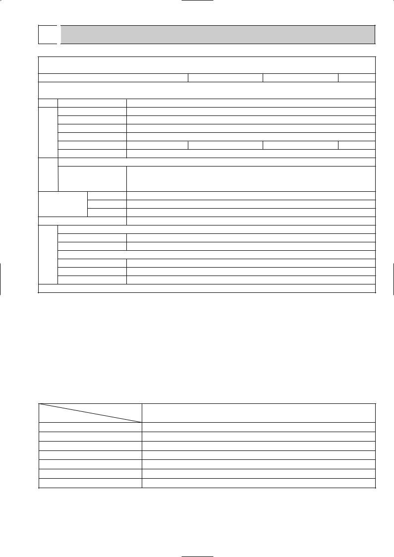
 SPECIFICATIONS
Indoor model
Function
Power supply
Capacity Air flow (High/Med./Low)
|
|
Power outlet |
||
Electrical |
data |
Running current 1 |
||
Power input |
Rated frequency |
|||
|
|
|||
|
|
Dew prevention heater |
||
|
|
Power factor 1 |
||
|
|
Fan motor current 1 |
||
Fan |
motor |
Model |
|
|
Winding |
|
|||
|
|
|
||
|
|
resistance (at20:) |
||
|
|
|
Width |
|
Dimensions |
Height |
|||
|
|
|
Depth |
|
|
|
Weight |
|
|
|
|
Air direction |
||
|
|
Sound level(High/Med./Low) |
||
Special |
remarks |
Fan speed(High/Med./Low) |
||
Thermistor RT11(at25:) |
||||
|
|
Fan speed |
regulator |
|
Thermistor RT12(at25:)
Thermistor RT13(at25:) Remote controller model
|
SLZ-A09AR.TH |
|
SLZ-A12AR.TH |
SLZ-A18AR.TH |
|||
|
Cooling |
Heating |
|
Cooling |
Heating |
Cooling |
Heating |
|
Single phase |
|
Single phase |
Single phase |
|||
|
230V, 50Hz |
|
230V, 50Hz |
230V, 50Hz |
|||
K /h |
600/540/480 |
|
660/600/540 |
660/600/540 |
|||
A |
10 |
|
|
10 |
|
20 |
|
A |
0.18 |
|
0.23 |
|
0.24 |
||
W |
40 |
|
|
52 |
|
53 |
|
(kW) |
0.014 |
|
0.014 |
|
0.014 |
||
% |
91 |
92 |
|
94 |
95 |
97 |
97 |
A |
0.18 |
|
0.23 |
|
0.24 |
||
|
PK6V15-LA |
|
PK6V20-LE |
PK6V20-LF |
|||
|
WHT-BLK : 407 |
BLK-BLU : 55 |
WHT-BLK : 384 |
BLK-BLU : 111 |
WHT-BLK : 317 BLK-BLU : 88 |
||
" |
BLU-YLW : 31 |
YLW-BRN : 30 |
BLU-YLW : 49 |
YLW-BRN : 46 |
BLU-YLW : 52 YLW-BRN : 45 |
||
|
BRN-RED : 165 |
|
BRN-RED : 311 |
BRN-RED : 301 |
|||
mm(in) |
|
UNIT : 570(22-7/16) |
PANEL : 650(25-9/16) |
|
|||
mm(in) |
|
UNIT : 208(8-3/16) |
PANEL : 20(13/16) |
|
|||
mm(in) |
|
UNIT : 570(22-7/16) |
PANEL : 650(25-9/16) |
|
|||
kg |
|
UNIT : 16.5 |
|
PANEL : 3 |
|
|
|
|
4 |
|
|
|
4 |
|
4 |
dB(A) |
38/35/32 |
|
39/37/34 |
40/38/35 |
|||
rpm |
650/580/530 |
|
690/630/570 |
710/650/590 |
|||
|
3 |
|
|
|
3 |
|
3 |
k" |
10 |
|
|
10 |
|
10 |
|
k" |
10 |
|
|
10 |
|
10 |
|
k" |
10 |
|
|
10 |
|
10 |
|
|
MPPC |
|
MPPC |
|
MPPC |
||
|
|
|
|
|
|
|
|
NOTE : Test conditions are based on ISO 5151
Cooling : Indoor |
D.B. 27: W.B. 19: |
Outdoor D.B. 35: W.B. 24: |
|
Heating : Indoor |
D.B. 20: W.B. 15: |
Outdoor D.B. 7: W.B. 6: Refrigerant piping length (one way): 5m
1 Measured under rated operating frequency.
Specifications and rating conditions of main electric parts
INDOOR UNIT
Item |
Model |
|
|
Indoor fan capacitor |
(C1) |
Fuse |
(F11) |
Vane motor |
(MV) |
Terminal block |
(TB) |
Contactor |
(52C) |
Indoor fan motor thermal fuse |
|
Cord Heater |
(H2) |
SLZ-A09AR.TH SLZ-A12AR.TH SLZ-A18AR.TH
1.5+ 440V
250V 3.15A MSBPC20 12V 250"
POWER SUPPLY : 3P TO OUTDOOR UNIT : 4P
G4A-1A-E-PS 12V DC 145:i2:
240V AC 15W
3

NOISE CRITERION CURVES
SLZ-A09AR.TH |
|
|
|
|
|
<50Hz> |
|||
|
|
NOTCH |
SPL(dB) |
LINE |
|||||
|
|
|
|
|
|
|
Hi |
38 |
|
|
|
|
|
|
|
|
Me |
35 |
|
|
|
|
|
|
|
|
Lo |
32 |
|
|
90 |
|
|
|
|
|
|
|
|
bar) |
80 |
|
|
|
|
|
|
|
|
= 0.0002 |
70 |
|
|
|
|
|
|
|
|
dB (0 dB |
|
|
|
|
|
|
|
NC-70 |
|
|
|
|
|
|
|
|
|
||
60 |
|
|
|
|
|
|
|
|
|
LEVEL, |
|
|
|
|
|
|
|
|
|
|
|
|
|
|
|
|
|
NC-60 |
|
|
|
|
|
|
|
|
|
|
|
PRESSURE |
50 |
|
|
|
|
|
|
|
|
|
|
|
|
|
|
|
|
NC-50 |
|
40 |
|
|
|
|
|
|
|
|
|
SOUND |
|
|
|
|
|
|
|
|
|
|
|
|
|
|
|
|
|
NC-40 |
|
|
|
|
|
|
|
|
|
|
|
BAND |
30 |
|
|
|
|
|
|
|
|
|
|
|
|
|
|
|
|
NC-30 |
|
|
|
|
|
|
|
|
|
|
|
OCTAVE |
20 |
APPROXIMATE |
|
|
|
|
|
|
|
|
TERESHOLD OF |
|
|
|
|
|
|
||
|
HEARING FOR |
|
|
|
|
|
NC-20 |
||
|
|
CONTINUOUS |
|
|
|
|
|
||
|
|
|
|
|
|
|
|
||
|
|
NOISE |
|
|
|
|
|
|
|
|
10 |
63 |
125 |
250 |
500 |
1000 |
2000 |
4000 |
8000 |
|
|
||||||||
BAND CENTER FREQUENCIES, Hz
SLZ-A18AR.TH |
|
|
|
|
|
<50Hz> |
|||
|
|
NOTCH |
SPL(dB) |
LINE |
|||||
|
|
|
|
|
|
|
Hi |
40 |
|
|
|
|
|
|
|
|
Me |
38 |
|
|
|
|
|
|
|
|
Lo |
35 |
|
|
90 |
|
|
|
|
|
|
|
|
bar) |
80 |
|
|
|
|
|
|
|
|
= 0.0002 |
70 |
|
|
|
|
|
|
|
|
dB (0 dB |
|
|
|
|
|
|
|
NC-70 |
|
|
|
|
|
|
|
|
|
||
60 |
|
|
|
|
|
|
|
|
|
LEVEL, |
|
|
|
|
|
|
|
|
|
|
|
|
|
|
|
|
|
NC-60 |
|
|
|
|
|
|
|
|
|
|
|
PRESSURE |
50 |
|
|
|
|
|
|
|
|
|
|
|
|
|
|
|
|
NC-50 |
|
40 |
|
|
|
|
|
|
|
|
|
SOUND |
|
|
|
|
|
|
|
|
|
|
|
|
|
|
|
|
|
NC-40 |
|
|
|
|
|
|
|
|
|
|
|
BAND |
30 |
|
|
|
|
|
|
|
|
|
|
|
|
|
|
|
|
NC-30 |
|
|
|
|
|
|
|
|
|
|
|
OCTAVE |
20 |
APPROXIMATE |
|
|
|
|
|
|
|
|
TERESHOLD OF |
|
|
|
|
|
|
||
|
HEARING FOR |
|
|
|
|
|
NC-20 |
||
|
|
CONTINUOUS |
|
|
|
|
|
||
|
|
|
|
|
|
|
|
||
|
|
NOISE |
|
|
|
|
|
|
|
|
10 |
63 |
125 |
250 |
500 |
1000 |
2000 |
4000 |
8000 |
|
|
||||||||
BAND CENTER FREQUENCIES, Hz
SLZ-A12AR.TH |
|
|
|
|
|
<50Hz> |
|||
|
|
NOTCH |
SPL(dB) |
LINE |
|||||
|
|
|
|
|
|
|
Hi |
39 |
|
|
|
|
|
|
|
|
Me |
37 |
|
|
|
|
|
|
|
|
Lo |
34 |
|
|
90 |
|
|
|
|
|
|
|
|
bar) |
80 |
|
|
|
|
|
|
|
|
= 0.0002 |
70 |
|
|
|
|
|
|
|
|
dB (0 dB |
|
|
|
|
|
|
|
NC-70 |
|
|
|
|
|
|
|
|
|
||
60 |
|
|
|
|
|
|
|
|
|
LEVEL, |
|
|
|
|
|
|
|
|
|
|
|
|
|
|
|
|
|
NC-60 |
|
|
|
|
|
|
|
|
|
|
|
PRESSURE |
50 |
|
|
|
|
|
|
|
|
|
|
|
|
|
|
|
|
NC-50 |
|
40 |
|
|
|
|
|
|
|
|
|
SOUND |
|
|
|
|
|
|
|
|
|
|
|
|
|
|
|
|
|
NC-40 |
|
|
|
|
|
|
|
|
|
|
|
BAND |
30 |
|
|
|
|
|
|
|
|
|
|
|
|
|
|
|
|
NC-30 |
|
|
|
|
|
|
|
|
|
|
|
OCTAVE |
20 |
APPROXIMATE |
|
|
|
|
|
|
|
|
TERESHOLD OF |
|
|
|
|
|
|
||
|
HEARING FOR |
|
|
|
|
|
NC-20 |
||
|
|
CONTINUOUS |
|
|
|
|
|
||
|
|
|
|
|
|
|
|
||
|
|
NOISE |
|
|
|
|
|
|
|
|
10 |
63 |
125 |
250 |
500 |
1000 |
2000 |
4000 |
8000 |
|
|
||||||||
BAND CENTER FREQUENCIES, Hz
UNIT
CEILING
1.5m
MICROPHONE
NOTE: The sound level is measured in an anechoic room where echoes are few, when compressor stops. The sound may be bigger than displayed level under actual installation condition by surrounding echoes. The sound level can be higher by about 2 dB than the displayed level during cooling and heating operation.
4
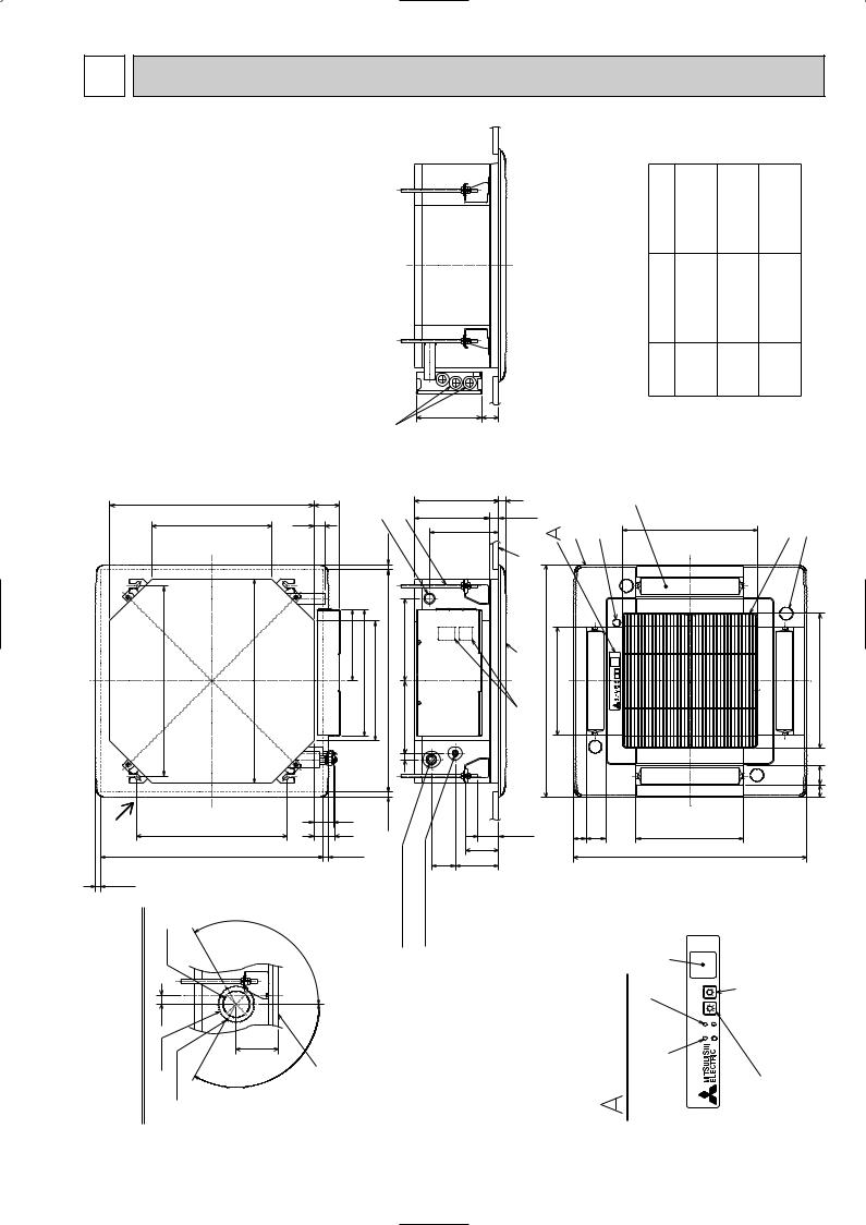
3 OUTLINES AND DIMENSIONS
SLZ-A09AR.TH
SLZ-A12AR.TH
SLZ-A18AR.TH
|
|
|
Wiring entry |
570 |
72 |
Drainpipe |
VP-25 connection (O.D.[32) Suspension bolt M10 or 3/8 (procure locally) |
|
|
||
335 |
31 |
|
15~37 |
|
|
|
|
530 |
Suspension bolt pitch |
570 |
199 352 335 576~620 Ceiling hole |
202 230 |
|
|
|
|
|
|
|
|
17 |
|
Freshair intake |
|
Suspensionboltpitch |
56 |
15~37 |
(gas) |
(liquid) |
|
|
|
|
|
|
|
||
|
|
420 |
|
57 |
|
|
|
|
576~620Ceilinghole |
|
15~37 |
|
|
|
|
15~37 |
|
|
|
|
|
pipe |
pipe |
[73.4 outCuthole |
|
|
|
Refrigerent |
Refrigerent |
||
intake |
|
° |
|
||||
|
|
|
|
120 |
|
|
|
of fresh air |
25 |
[-32.8 hole Burringhole |
|
Ceilingsurface |
|
|
|
Detaildrawing |
[100 |
118 |
|
|
|
||
|
|
|
|
° |
|
|
|
|
|
|
|
120 |
|
|
|
Unit : mm
|
|
|
|
|
|
Refrigerent pipe |
(gas) |
[9.52mm flared connection |
3/8F |
[9.52mm flared connection |
3/8F |
[12.7mm flared connection |
1/2F |
|
|
|
|
|
|
|
Refrigerent pipe |
(liquid) |
[6.35mm flared connection |
1/4F |
[6.35mm flared connection |
1/4F |
[6.35mm flared connection |
1/4F |
|
|
|
|
|
|
|
Models |
|
SLZ-A09AR |
|
SLZ-A12AR |
|
SLZ-A18AR |
|
|
182 |
48 |
|
|
|
|
|
|
|
|
|
|
|
|
|
235 |
20 |
|
Grille |
holeDrain |
Auto vane |
|
|
|
|
|
|
|
intakeAir grille |
Vanemotor |
|
|
|
|
|
|
|
|
|
|
|
|
|
||
208 |
0 |
27 |
|
|
|
|
Airintakehole |
|
|
|
|
|||
|
+5 |
|
|
|
|
|
377 |
|
|
|
|
|
|
|
193 |
|
|
|
|
|
|
|
|
|
|
|
|
||
|
|
|
|
|
|
|
|
|
|
|
|
|
||
|
|
|
|
|
|
|
|
|
|
|
|
|
|
|
|
Ceiling surface |
|
|
V/M |
|
|
|
|
|
|
|
V/M |
|
|
|
Grille |
|
650 301 Air outlet hole |
|
|
|
|
|
|
|
|
|
|
377 Air intake hole |
|
Terminal block |
|
|
|
|
|
|
|
|
|
|
|||
|
|
|
|
V/M |
|
|
|
|
|
|
|
|
|
|
|
Suspension bolt lower edge |
|
|
|
|
|
Airoutlethole |
V/M |
|
|
35 55 |
|||
|
|
|
|
|
|
|
|
|
|
|
|
|||
|
38~58 |
35 |
55 |
|
|
|
301 |
|
|
|
|
|
|
|
|
|
|
|
|
|
|
|
|
|
|
|
|||
|
93 |
|
|
|
|
|
|
650 |
|
|
|
|
|
|
66 |
121 |
|
|
|
|
|
|
|
|
|
|
|
|
|
|
|
PANEL)(WIRELESS |
|
lampBYDEFROST/STAND |
|
|
Emergencyoperation |
|
switch(heating)operationEmergency |
|
|
|||
|
|
|
|
lampOperation |
|
|
switch(cooling) |
|
|
|||||
|
|
|
|
|
|
Receiver |
|
|
|
|
|
|
|
|
5
Unit : mm
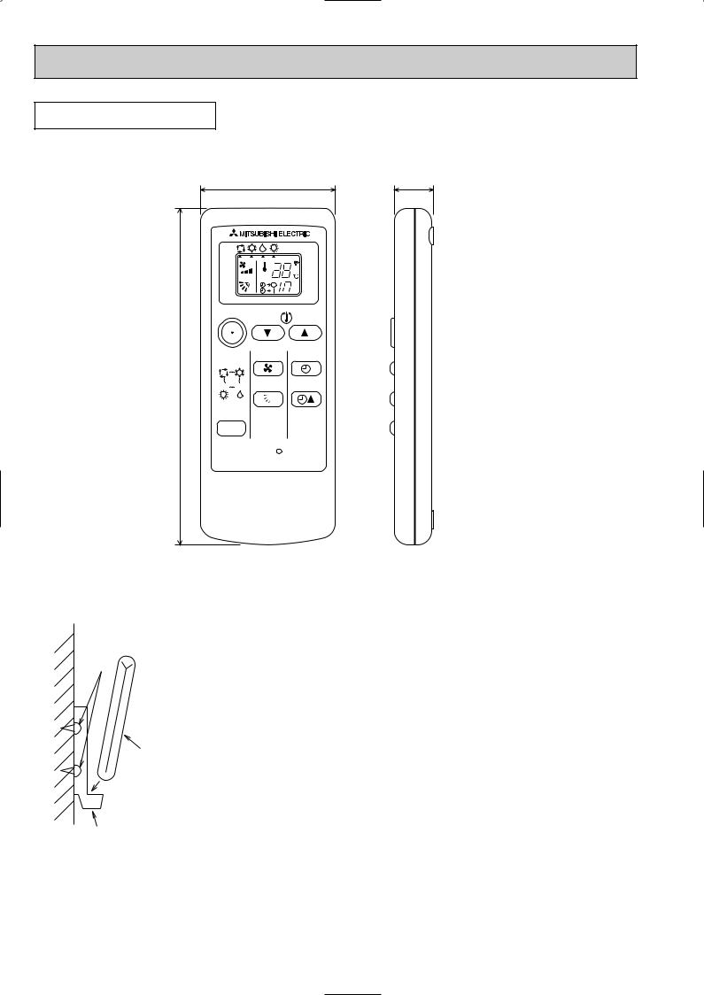
REMOTE CONTROLLER
57 |
17.5 |
|
|
|
h |
|
|
ON/OFF |
TOO |
TOO |
|
|
|
WARM |
COOL |
|
|
AUTO COOL |
FAN |
SELECT |
|
140 |
|
|
||
HEAT DRY |
VANE |
TIME |
||
|
||||
|
MODE |
|
|
|
|
|
|
RESET |
D
B
A
C
Installation area
•Area in which the remote controller is not exposed direct sunshine.
•Area in which there is no nearby heating source.
•Area in which the remote controller is not exposed to cold (or hot) winds.
•Area in which the remote controller can be operated easily
•Area in which the remote controller is beyond the reach of children.
Installation method
1 Attach the remote controller holder to the desired location using two tapping screws. 2 Place the lower end of the controller into the holder.
A Wireless remote controller (Accessory) B Wall
C Remote controller holder (Accessory) D Fixing screw (Accessory)
•The signal can travel up to approximately 7 meters (in a straight line) within 45 degrees to both right and left of the center line of the receiver.
In addition, the signal may not be received if there is interference of light of fluorescent lights or strong sunlight.
6
4 
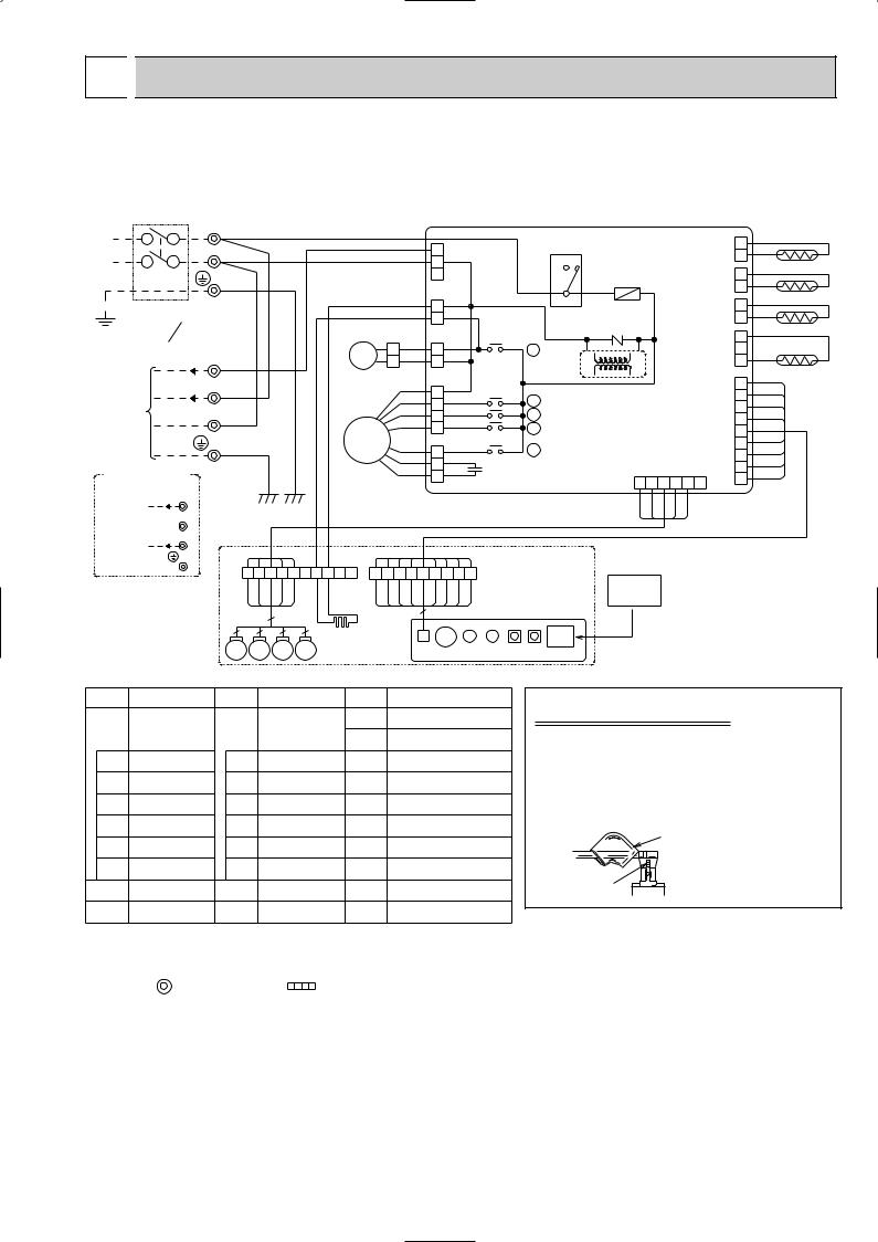
 WIRING DIAGRAM
SLZ-A09AR.TH
SLZ-A12AR.TH
SLZ-A18AR.TH
CIRCUIT BREAKER |
TB |
|
|
|
|
|
|
||
|
|
L |
w WHT |
|
|
|
|
|
|
|
|
N |
w BLU |
|
|
|
|
|
|
|
|
|
GRN/YLW |
|
|
|
|
|
|
POWER SUPPLY |
|
|
|
|
|
|
|
||
~/N |
|
|
|
|
|
|
|
|
|
220-240V 220V |
|
|
|
|
|
|
|
||
50Hz |
60Hz |
TB |
|
|
|
|
|
|
|
|
|
|
|
|
|
DP |
|||
12VDC 3 |
w RED |
|
|
|
|||||
FOR A09/12 |
|
|
|
|
|
|
|
|
|
(1:1 SYSTEM) 220-240V~ 2 |
w WHT |
|
|
|
|
|
|||
TO OUTDOOR |
|
N |
|
|
|
|
|
|
|
UNIT |
|
w BLU |
|
|
|
|
|
||
CONNECTING |
|
|
|
|
|
|
|
MF |
|
|
|
|
GRN/YLW |
|
|
||||
|
|
|
|
|
|
|
|||
FOR A18 (1:1 SYSTEM) |
|
|
|
|
|
|
|
|
|
OR MULTI SYSTEM |
|
|
|
|
|
|
|
|
|
12VDC 3 |
|
|
|
|
|
|
|
|
|
TO OUTDOOR |
2 |
|
|
|
|
|
|
|
|
UNIT |
|
|
|
|
|
|
|
|
|
CONNECTING |
N |
|
GRILLE |
|
|
|
|
|
|
|
|
|
|
|
|
|
|||
|
|
|
1 2 |
3 6 |
7 4 5 10 8 9 |
1 |
|||
|
|
|
BLU |
WHT YLW ORN |
RED |
YLW YLW |
BRN |
RED |
|
|
|
|
|
|
5 |
|
|
|
|
|
|
|
5 |
|
5 |
5 |
5 |
H2 |
|
|
|
|
MV |
MV MV MV |
|
|
|||
[LEGEND]
|
|
|
|
|
|
|
|
|
|
|
|
|
|
|
|
|
|
I.B |
|
|
|
|
|
|
|
|
CND(POWER) |
|
52C |
|
|
|
|
|
CN29 |
2 |
|
||||
|
|
|
|
|
5 |
|
|
|
|
|
(2 PHASE) |
|
||||||||
|
|
|
|
|
3 |
RED |
|
|
|
|
4 |
|
|
|
|
|
BLK |
1 |
RT13 |
|
|
|
|
|
|
|
|
|
|
|
|
|
|
|
|
|
|
||||
|
|
|
|
|
|
|
|
|
|
|
|
|
|
|
|
|
CN21 |
|
||
|
|
|
|
|
1 |
CNC |
|
|
|
|
w |
FUSE |
|
|
|
2 |
|
|||
|
|
|
|
|
|
|
|
|
|
|
|
(LIQUID) |
1 |
|
||||||
|
YLW |
(HEATER) |
|
|
|
3 |
|
|
|
|
|
WHT |
RT12 |
|||||||
|
|
3 RED |
|
|
|
|
|
|
|
|
|
CN20 |
2 |
|
||||||
|
YLW |
|
1 |
|
|
|
|
|
|
|
|
|
|
|
|
(INTAKE) |
1 |
|
||
|
|
|
|
|
|
|
|
|
|
|
|
|
ZNR1 |
|
|
|
|
RED |
|
RT11 |
|
|
|
|
CNP(PUMP) |
|
X1 |
|
|
|
|
|
|
CN31 |
3 |
||||||
|
YLW |
|
|
|
|
|
|
|
|
|
||||||||||
|
|
3 BLU |
|
|
|
|
|
|
|
|
|
|
||||||||
3 |
|
|
|
|
X1 |
|
|
|
|
|
|
(DRAIN) |
2 |
|
||||||
1 |
YLW |
|
1 |
|
|
|
|
|
TRANS |
|
|
|
|
|
WHT 1 |
DS |
||||
|
|
|
|
|
|
|
|
|
|
|
DC13.1V |
|
|
|
|
|
|
|
||
|
WHT |
FAN1(FAN) |
|
|
|
|
|
|
|
|
|
|
9 |
SKY BLU |
||||||
|
|
7 |
WHT |
|
|
X2 |
|
|
|
|
|
|
|
|
8 |
PINK |
||||
|
BLK |
|
|
|
|
|
X2 |
|
|
|
|
|
|
|
GRY |
|||||
|
|
5 |
|
|
|
|
|
|
|
|
|
|
|
7 |
||||||
|
BLU |
|
|
|
|
|
X3 |
X3 |
|
|
|
|
|
|
CN90 |
VLT |
||||
|
|
3 |
|
|
|
|
|
|
|
|
|
|
6 |
|||||||
|
YLW |
|
1 |
|
|
|
|
X4 |
X4 |
|
|
|
|
(WIRELESS) |
BLU |
|||||
|
|
|
|
|
FAN2(FAN) |
|
|
|
|
|
|
|
WHT |
5 |
YLW |
|||||
|
|
|
|
|
|
X5 |
|
|
|
|
|
|
|
|
4 |
|||||
|
BRN |
|
5 WHT |
|
|
X5 |
|
|
|
CN6V |
|
ORN |
||||||||
|
|
|
|
|
|
|
|
3 |
||||||||||||
|
RED |
|
3 |
|
|
|
C1 |
|
|
|
|
(VANE) |
|
2 |
RED |
|||||
|
ORN |
|
|
|
|
|
|
|
|
|
GRN |
|
BRN |
|||||||
|
|
1 |
|
|
|
|
|
|
|
1 |
2 |
6 |
1 |
|||||||
|
|
|
|
|
|
|
|
|
|
|
|
|
3 |
4 |
5 |
|
|
|||
|
|
|
|
|
|
|
|
|
|
|
|
|
BLU |
WHT |
YLW |
ORN |
RED |
|
|
|
2 |
3 |
4 |
5 |
6 |
7 |
8 |
9 |
|
|
|
|
W.R |
|
|
|
|
|
|
|
|
|
|
|
W.B |
|
|
|
|
|
|
|
|
|||||||||
ORN |
YLW |
9BLUVLT |
GRY PINK |
|
BLUSKY |
|
|
|
REMOTE |
|
|
|
|
|
|
|||||
|
|
|
|
|
|
|
|
|
|
|
|
|
CONTROLLER |
|
|
|
|
|
||
|
|
|
|
|
|
BZ |
|
|
|
|
|
|
|
|
|
|
|
|
|
|
|
|
CNB |
|
|
LED2 |
LED1 SW1 |
SW2 |
RU |
|
|
|
|
|
|
|
|
||||
|
|
|
|
|
|
|
|
|
|
|
|
|
|
|
|
|
|
|
|
|
SYMBOL |
NAME |
SYMBOL |
NAME |
SYMBOL |
NAME |
|
I.B |
INDOOR |
|
WIRELESS REMOTE |
DP |
DRAIN-UP |
|
W.B |
MACHINE |
|||||
|
CONTROLLER |
CONTROLLER |
|
|||
|
|
DS |
DRAIN SENSOR |
|||
|
BOARD |
|
BOARD |
|||
C1 |
FAN MOTOR |
BZ |
BUZZER |
H2 |
DEW PREVENTION |
|
CAPACITOR |
HEATER |
|||||
|
|
|
|
|||
FUSE FUSE(3.15A) |
LED1 |
LED |
MF |
FAN MOTOR |
||
(RUN INDICATOR) |
||||||
X1 |
RELAY(D.PUMP |
LED2 |
LED |
MV |
VANE MOTOR |
|
/D.HEATER) |
(HOT ADJUST) |
|||||
X2-X5 |
RELAY |
SW1 |
SWITCH |
RT11 |
ROOM TEMPERATURE |
|
(FAN MOTOR) |
(HEATING ON/OFF) |
THERMISTOR |
||||
ZNR1 |
VARISTOR |
SW2 |
SWITCH |
RT12 |
PIPE TEMPERATURE |
|
(COOLING ON/OFF) |
THERMISTOR / LIQUID |
|||||
|
||||||
52C |
COMPRESSOR |
RU |
RECEVING UNIT |
RT13 |
CONDENSER/EVAPORATOR |
|
CONTACTOR |
TEMPERATURE THERMISTOR |
|||||
|
|
|
|
|||
|
|
|
|
TB |
TERMINAL BLOCK |
|
|
|
|
|
|
WIRELESS REMOTE |
|
W.R CONTROLLER
How to remove the terminals shown at " w " mark.
" w " shows the terminals with a lock mechanism, so they cannot be removed when you pull the lead wire. Be sure to pull the wire by pushing the locking lever (projected part) of the terminal with a finger.
sleeve 1 Slide the sleeve. 2 Pull the wire
while pushing the locking lever.
locking lever
NOTES: 1.About the outdoor side electric wiring refer to the outdoor unit electlic wiring diagram for servicing.
2.Use copper conductors only. (For field wiring) 3.Symbols below indicate.
: Terminal block
The 12V DC is NOT always against the ground. Terminal 3 has 12V DC against terminal N.
However, between 3 and 2, these terminals are NOT electrically insulated by the transformer or other device.
7
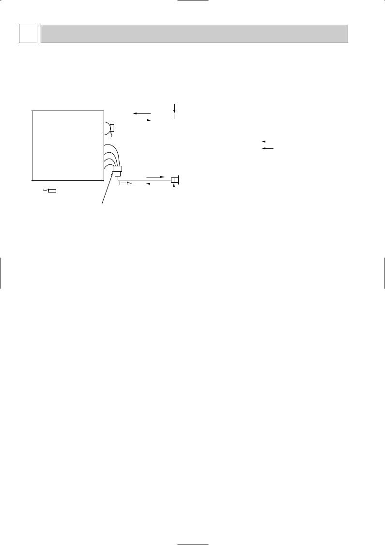
5 REFRIGERANT SYSTEM DIAGRAM
SLZ-A09AR.TH
SLZ-A12AR.TH
SLZ-A18AR.TH
Strainer #50
Heat exchanger
|
|
|
|
|
|
|
|
|
|
|
|
|
|
|
|
|
|
|
|
|
Refrigerant GAS pipe connection |
|||
|
|
|
|
|
|
|
|
|
|
|
|
|
|
|
|
|
|
|
|
|
(Flare) |
|||
|
|
|
|
|
|
|
|
|
|
|
|
|
|
|
|
|
|
|
|
|
||||
|
|
|
|
|
|
|
|
|
|
|
|
|
|
|
||||||||||
|
|
|
|
|
|
|
|
|
|
|
|
|
Condenser/evaporator |
|||||||||||
|
|
|
|
|
|
|
|
|
|
|
|
|
||||||||||||
|
|
|
|
|
|
|
|
|
|
|
|
|
temperature thermistor |
|||||||||||
|
|
|
|
|
|
|
|
|
|
|
|
|
||||||||||||
|
|
|
|
|
|
|
|
|
|
|
|
|
(RT13) |
|
||||||||||
|
|
|
|
|
|
|
|
|
|
|
|
|
|
|
|
|||||||||
|
|
|
|
|
|
|
|
|
|
|
|
|
|
|
|
|
|
|
|
|
|
|
|
Refrigerant flow in cooling |
|
|
|
|
|
|
|
|
|
|
|
|
|
|
|
|
|
|
|
|
|
|
|
|
|
|
|
|
|
|
|
|
|
|
|
|
|
|
|
|
|
|
|
|
|
|
|
|
|
Refrigerant flow in heating |
|
|
|
|
|
|
|
|
|
|
|
|
|
|
|
|
|
|
|
|
|
|
|
||
|
|
|
|
|
|
|
|
|
|
|
|
|
|
|
|
|
|
|
|
|
Refrigerant LIQUID pipe connection |
|||
|
|
|
|
|
|
|
|
|
|
|
|
|
|
|
|
|
|
|
|
|
||||
|
|
|
|
|
|
|
|
|
|
|
|
|
|
|
|
|
|
|
|
|
||||
|
|
|
|
|
|
|
|
|
|
|
|
|
|
|
|
|
|
|
|
|
||||
|
|
|
|
|
|
|
|
|
|
|
|
|
|
|
|
|
|
|
|
|
||||
|
|
|
|
|
|
|
|
|
|
|
|
|
|
|
||||||||||
|
|
|
|
|
|
|
|
|
|
|
|
|
|
|
|
|
|
|
|
|
(Flare) |
|||
|
|
|
|
|
|
|
|
|
|
|
|
|
Pipe temperature |
|
|
|||||||||
|
|
|
|
|
|
|
|
|
|
|
|
|
|
|||||||||||
Room temperature |
|
|
|
|
|
|
|
thermistor/liquid |
|
|
||||||||||||||
thermistor (RT11) |
|
|
|
|
|
|
|
(RT12) |
|
|
||||||||||||||
|
|
|
|
|
|
|
|
|||||||||||||||||
|
|
|
|
|
|
Distributor |
|
|
|
|
Strainer |
|||||||||||||
|
|
|
|
|
|
#50 |
|
|
|
|
||||||||||||||
|
|
|
|
|
|
with strainer |
|
|
|
|
||||||||||||||
|
|
|
|
|
|
|
|
|
|
|
|
|
|
|
|
|
|
|||||||
|
|
|
|
|
|
#50 |
|
|
|
|
|
|
|
|
|
|
|
|
|
|
|
|
||
8
 Loading...