

Page 1

DC-N2/DC-N2T/DC-N2S
Diagnostic Ultrasound System
Operator’s Manual
[Advanced Volume]
Page 2

Page 3

Content
Content ....................................................................................................................................i
Intellectual Property Statement .......................................................................................................... I
Preface .............................................................................................................................................. II
Product Differences ........................................................................................................................... II
Safety Precautions ........................................................................................................................... III
1 Overview ...................................................................................................................... 1-1
1.1 Basic Operations and Buttons .............................................................................................. 1-1
1.2 Measurement Menu ............................................................................................................. 1-2
1.2.1 Menu Title ..................................................................................................................... 1-2
1.2.2 Location Tags ................................................................................................................ 1-3
1.2.3 Measurement Tools ...................................................................................................... 1-3
1.2.4 Other ............................................................................................................................. 1-4
1.3 Measurement, Calculation and Study .................................................................................. 1-4
1.4 Measure Caliper ................................................................................................................... 1-5
1.5 Result Window ..................................................................................................................... 1-5
1.5.1 Result Display ............................................................................................................... 1-5
1.5.2 Moving Result Window ................................................................................................. 1-5
1.5.3 Result Assignment ........................................................................................................ 1-6
1.6 Cross-window Measurement ................................................................................................ 1-7
1.7 Exam Report ........................................................................................................................ 1-7
1.7.1 Viewing Report ............................................................................................................. 1-7
1.7.2 Editing Report ............................................................................................................... 1-8
1.7.3 Viewing History Report ............................................................................................... 1-10
1.7.4 Printing Report ............................................................................................................ 1-10
1.7.5 Exporting Report ......................................................................................................... 1-11
1.7.6 Fetal Growth Curve ..................................................................................................... 1-11
2 Preset ........................................................................................................................... 2-1
2.1 Basic Preset Procedures ...................................................................................................... 2-1
2.2 Measurement Parameters .................................................................................................... 2-1
2.3 Obstetric Preset .................................................................................................................... 2-2
2.3.1 Obstetric Formulae ....................................................................................................... 2-3
2.3.2 Obstetric Preset Operations ......................................................................................... 2-7
2.4 Measure Preset .................................................................................................................... 2-9
2.4.1 Preset of General Measurement .................................................................................. 2-9
2.4.2 Application Measurement Preset ................................................................................ 2-11
2.5 Fast OB Measurement ....................................................................................................... 2-15
3 General Measurement ................................................................................................ 3-1
3.1 Basic Procedures of General Measurement ........................................................................ 3-1
3.2 2D General Measurements .................................................................................................. 3-1
3.2.1 Depth ............................................................................................................................ 3-1
3.2.2 Distance ........................................................................................................................ 3-1
3.2.3 Angle ............................................................................................................................. 3-2
3.2.4 Area&Circ ..................................................................................................................... 3-2
3.2.5 Volume .......................................................................................................................... 3-3
3.2.6 Double Dist ................................................................................................................... 3-4
i
Page 4

3.2.7 Parallel .......................................................................................................................... 3-5
3.2.8 Trace Length ................................................................................................................. 3-5
3.2.9 Ratio (D) ....................................................................................................................... 3-5
3.2.10 Ratio (A) ........................................................................................................................ 3-6
3.2.11 B-Profile ........................................................................................................................ 3-6
3.2.12 B-Hist ............................................................................................................................ 3-6
3.2.13 Color Vel ....................................................................................................................... 3-7
3.2.14 Volume Flow ................................................................................................................. 3-7
3.2.15 IMT ................................................................................................................................ 3-7
3.3 M General Measurements .................................................................................................... 3-7
3.3.1 Distance ........................................................................................................................ 3-7
3.3.2 Time .............................................................................................................................. 3-8
3.3.3 Slope ............................................................................................................................. 3-8
3.3.4 Velocity ......................................................................................................................... 3-8
3.3.5 HR ................................................................................................................................. 3-9
3.4 Doppler General Measurements .......................................................................................... 3-9
3.4.1 Time .............................................................................................................................. 3-9
3.4.2 HR ................................................................................................................................. 3-9
3.4.3 D Vel ............................................................................................................................. 3-9
3.4.4 Acceleration .................................................................................................................. 3-9
3.4.5 D Trace ....................................................................................................................... 3-10
3.4.6 PS/ED ......................................................................................................................... 3-13
3.4.7 Volume Flow ............................................................................................................... 3-13
3.5 References ......................................................................................................................... 3-14
4 Abdomen ..................................................................................................................... 4-1
4.1 Abdomen Exam Preparations .............................................................................................. 4-1
4.2 Basic Abdomen Measurement Procedures .......................................................................... 4-1
4.3 Abdomen Measurement Tools ............................................................................................. 4-1
4.4 Abdomen Measurement Operations .................................................................................... 4-4
4.5 Abdomen Exam Report ........................................................................................................ 4-4
5 Obstetrics .................................................................................................................... 5-1
5.1 Obstetric Exam Preparations ............................................................................................... 5-1
5.2 Basic Measurement Procedures .......................................................................................... 5-1
5.3 GA ........................................................................................................................................ 5-1
5.3.1 Clinical GA .................................................................................................................... 5-1
5.3.2 Ultrasound GA .............................................................................................................. 5-2
5.4 Obstetric Measurement Tools .............................................................................................. 5-4
5.5 Obstetric Measurement Operations ..................................................................................... 5-8
5.5.1 Measurement Tool Operations ..................................................................................... 5-8
5.5.2 Calculation Tool Operations .......................................................................................... 5-9
5.5.3 Study Tool Operations................................................................................................... 5-9
5.6 Multi-fetus Exam ................................................................................................................... 5-9
5.7 Obstetric Exam Report ....................................................................................................... 5-10
5.7.1 Fetal Biophysical Profile ............................................................................................. 5-10
5.7.2 Z-Score ....................................................................................................................... 5-11
5.7.3 Fetal Growth Curve ..................................................................................................... 5-11
5.8 References ......................................................................................................................... 5-12
6 Cardiology ................................................................................................................... 6-1
6.1 Cardiac Exam Preparations ................................................................................................. 6-1
6.2 Basic Cardiac Measurement Procedures ............................................................................ 6-1
ii
Page 5

6.3 Cardiac Measurement Tools ................................................................................................ 6-1
6.3.1 2D Cardiac Measurements ........................................................................................... 6-2
6.3.2 M Cardiac Measurements ............................................................................................ 6-4
6.3.3 Doppler Cardiac Measurements ................................................................................... 6-6
6.3.4 TDI Cardiac Measurements ........................................................................................ 6-10
6.4 Cardiac Measurement Operations ..................................................................................... 6-10
6.4.1 Measurement Tool Operations ................................................................................... 6-10
6.4.2 Calculation Tool Operations ........................................................................................ 6-10
6.4.3 Study Tool Operations................................................................................................. 6-11
6.5 Cardiac Exam Report ......................................................................................................... 6-34
6.6 References ......................................................................................................................... 6-34
7 Vascular ....................................................................................................................... 7-1
7.1 Vascular Exam Preparations ................................................................................................ 7-1
7.2 Basic Vascular Measurement Procedures ........................................................................... 7-1
7.3 Vascular Measurement Tools ............................................................................................... 7-1
7.4 Vascular Measurement Operations ...................................................................................... 7-4
7.4.1 Measurement Tool Operations ..................................................................................... 7-4
7.4.2 Calculation Tool Operations .......................................................................................... 7-4
7.4.3 Study Tool Operations................................................................................................... 7-4
7.5 Vascular Exam Report .......................................................................................................... 7-6
7.6 References ........................................................................................................................... 7-6
8 Gynecology ................................................................................................................. 8-1
8.1 Gynecology Exam Preparations ........................................................................................... 8-1
8.2 Basic Gynecology Measurement Procedures ...................................................................... 8-1
8.3 Gynecology Measurement Tools .......................................................................................... 8-1
8.4 Gynecology Measurement Operations................................................................................. 8-2
8.4.1 Measurement Tool Operations ..................................................................................... 8-2
8.4.2 Calculation Tool Operations .......................................................................................... 8-3
8.4.3 Study Tool Operations................................................................................................... 8-3
8.5 Gynecology Exam Report .................................................................................................... 8-4
8.6 References ........................................................................................................................... 8-4
9 Urology ........................................................................................................................ 9-1
9.1 Urology Exam Preparations ................................................................................................. 9-1
9.2 Basic Urology Measurement Procedures ............................................................................ 9-1
9.3 Urology Measurement Tools ................................................................................................ 9-1
9.4 Urology Measurement Operations ....................................................................................... 9-3
9.4.1 Measurement Tool Operations ..................................................................................... 9-3
9.4.2 Calculation Tool Operations .......................................................................................... 9-3
9.4.3 Study Tool Operations................................................................................................... 9-4
9.5 Urology Exam Report ........................................................................................................... 9-6
9.6 References ........................................................................................................................... 9-6
10 Small Parts ................................................................................................................ 10-1
10.1 Small Parts Exam Preparations ......................................................................................... 10-1
10.2 Basic Small Parts Measurement Procedures .................................................................... 10-1
10.3 Small Parts Measurement Tools......................................................................................... 10-1
10.4 Small Parts Measurement Operations ............................................................................... 10-2
10.4.1 Measurement Tool Operations ................................................................................... 10-2
10.4.2 Calculation Tool Operations ........................................................................................ 10-3
10.4.3 Study Tool Operations................................................................................................. 10-3
iii
Page 6

10.5 Small Parts Exam Report ................................................................................................... 10-3
10.6 References ......................................................................................................................... 10-4
11 Orthopedics ................................................................................................................11-1
11.1 Orthopedics Exam Preparations ........................................................................................ 11-1
11.2 Basic Orthopedics Measurement Procedures ................................................................... 11-1
11.3 Orthopedics Measurement Tools ....................................................................................... 11-1
11.4 HIP Measurement Operations ............................................................................................ 11-3
11.5 Orthopedics Exam Report .................................................................................................. 11-3
11.6 References ......................................................................................................................... 11-3
12 Emergency ................................................................................................................ 12-1
12.1 Basic Measurement Procedures ........................................................................................ 12-1
12.2 EM Measurement Tools ...................................................................................................... 12-1
12.3 EM Exam Report ................................................................................................................ 12-2
13 Nerve .......................................................................................................................... 13-1
13.1 Basic Measurement Procedures ........................................................................................ 13-1
13.2 Nerve Measurement Tools ................................................................................................. 13-1
13.3 Nerve Exam Report ............................................................................................................ 13-1
iv
Page 7

©2013-2014 Shenzhen Mindray Bio-medical Electronics Co., Ltd. All Rights Reserved.
For this Operator’s Manual, the issue date is 2014-04.
Intellectual Property Statement
SHENZHEN MINDRAY BIO-MEDICAL ELECTRONICS CO., LTD. (hereinafter called Mindray)
owns the intellectual property rights to this Mindray product and this manual. This manual may refer
to information protected by copyright or patents and does not convey any license under the patent
rights or copyright of Mindray, or of others.
Mindray intends to maintain the contents of this manual as confidential information. Disclosure of
the information in this manual in any manner whatsoever without the written permission of Mindray
is strictly forbidden.
Release, amendment, reproduction, distribution, rental, adaptation, translation or any other
derivative work of this manual in any manner whatsoever without the written permission of Mindray
is strictly forbidden.
IMPORTANT!
1.
No part of this manual may be copied or reprinted, in whole or in part, without written
permission.
2.
The contents of this manual are subject to change without prior notice and without our
legal obligation.
I
Page 8

Preface
This manual details the procedures for operating the DC-N2/DC-N2T/DC-N2S Diagnostic
Ultrasound System. Carefully read and understand the manual before using the system to ensure
its safe and correct operation.
NOTE: When you operate the system, you can refer to the following manuals:
Operator’s Manual (Basic Volume)
Acoustic output data
Depending on the software version, the preset settings, and optional configuration, the actual
interfaces may appear different from those shown in this manual.
NOTE: The functions described in this manual are not provided for all systems sold in all regions.
Functions that are available dependents on the specific system you purchased.
All the menus and screens in this manual take the system in full configuration as an example.
Product Differences
Models Functions
B-Hist B-Profile
DC-N2
DC-N2T
DC-N2S
√ √
√
×
×
√
II
Page 9

Safety Precautions
1. Meanings of Signal Words
In this manual, the signal words Danger, WARNING, CAUTION and NOTE are
used regarding safety and other important instructions. The signal words and their meanings are
defined as follows. Please understand their meanings clearly before reading this manual.
Signal word Meaning
Danger
Indicates an imminently hazardous situation that, if not avoided, will
result in death or serious injury.
WARNING
CAUTION
NOTE
2. Meaning of Safety Symbols
Symbol Description
3. Safety Precautions
Please observe the following precautions to ensure patient and operator’s safety when using this
system.
CAUTION:
Indicates a potentially hazardous situation that, if not avoided, could
result in death or serious injury.
Indicates a potentially hazardous situation that, if not avoided, may
result in minor or moderate injury.
Indicates a potentially hazardous situation that, if not avoided, may result in
property damage.
General warning, caution, risk of danger.
1.
Select the proper patient image and measurement tools.
Only the professionals can decide the appropriate
measurements and results.
2.
Confine measurement calipers to the actual Region of
Interest (ROI). Measurements that extend beyond the ROI
will be incorrect.
3.
Before examining a new patient, it is necessary to press the
< End Exam> key to end the current scan and delete the
patient information and data. Otherwise, new patient data
will be combined with the previous patient.
4.
When the system is turned OFF or the < End Exam> key is
pressed, all the data that have not been saved are lost.
5.
Changing modes during a measurement will delete the
General Measurement data.
6.
Pressing the < Freeze> key to unfreeze the image during a
measurement will clear the General Measurement data.
7.
Pressing the < Measure> key during a measurement will
clear the General Measurement data.
III
Page 10

8.
Pressing the < Clear> key will clear the measurement
caliper, all data in the result window, comments and body
mark.
9.
In dual-B imaging mode, the measurement results of the
merged image can be inaccurate. Therefore, the results are
provided for reference only, not for confirming a diagnosis.
10.
Quality of the extended image constructed in iScape
(panoramic imaging) dependents on the skill of operator.
Extra attention should be paid during the iScape
measurement since the results could be inaccurate.
11.
Ensure that measurement data correctly corresponds to the
fetus during the Obstetric Measurement.
12.
Fully understand the functionality of this system by
referring to the Operator’s Manual - Basic Volume.
13.
The auto measurement might not be accurate when the
result doesn’t match the image exactly, please make the
measurement manually.
IV
Page 11

1 Overview
1.1 Basic Operations and Buttons
Tips: The following descriptions for buttons and keys are used in this manual:
< >: Denotes key/ button on the control panel or keyboard. E.g. <Set>.
[ ]: Denotes button/item on the screen menu. E.g. [OK].
Click/Select [item/button]: to move the cursor over the item/button and press <Set>.
Basic Measurement Procedures
1. Press <End Exam> to start a new exam.
2. Press <Patient> and input the patient information.
It includes patient ID, name, height, weight etc. Type in manually for a new patient, or load an
existing patient from iStation or Worklist.
The patient information entered is used for measurement data storage, analysis and exam
report. For more details, refer to "Exam Preparation -> Patient Information" in the Operator's
Manual [Basic Volume].
3. Press <Probe> and select a proper exam mode.
For more details, refer to "Exam Preparation" in the Operator's Manual [Basic Volume].
4. Measure preset.
To preset measurement parameters, obstetric formula, general/ application measurement
packages etc. For details, refer to “2 Preset”.
5. Press <Measure> to start measurement.
6. Select an item in the measure menu.
For general and application measurement items (tools), see "3 General Measurement " and the
chapter of specified application measurements for details.
7. Press <Report> to view the exam report.
For report editing and browsing, see “1.7 Exam Report”.
Button Functions
Key Basic operations
Caliper
Measure
Update
Enters/exits general measurement.
Press <Esc> to exit measurement status.
To enter/exit the application measurement.
Press <Esc> to exit measurement status.
Press <Update> to switch between the fixed end and active end of the
caliper during a measurement.
1-1 Overview
Page 12

Key Basic operations
Set
Back
Clear
Report To enter/ exit the report page.
Cursor To show the cursor.
Palm Switch To move the cursor.
Multifunction knob
(Nav.)
For details on key functions, see “System Overview” in the Operator's Manual [Basic Volume].
To select an item on the measurement menu and press <Set> to activate it.
Press <Set> confirm and end the current operation during measurement.
To return to the previous measurement step, or delete the caliper
backwards.
To clear all measurement calipers on the screen and data in the result
window.
To enable the commonly used measure function or used for selecting
measurement item by rotating.
1.2 Measurement Menu
Menus of General and Application measurement are different. measurement menu, refer to "3
General Measurement" and the specified application measurement chapter. Measurement menu
items are as follows:
Menu title
Location Tags
Tools
Other
1.2.1 Menu Title
It displays the name of the measure menu, i.e. name of the measurement package.
Overview 1-2
Page 13

To switch to other measurement menus
1. Move cursor to the menu title and the submenu pops up displaying other measure
packages available.
2. Move the cursor to an item and press <Set>.
1.2.2 Location Tags
The location widgets are used to select locations of the measurement.
z Side (Left/Right): Used to the item (e.g. kidney) that contains measurement of left/ right
side parameters respectively.
z Location (Prox/Mid/Dist): Used to items (e.g. vascular) contains measurement of Proximal,
Middle or Distal parameters.
To Select the Measurement Location:
1. Move the cursor to the location widgets (e.g. Side).
2. Press <Set> to select the Measurement location.
Tips: The location widgets are applicable only in application measurement.
1.2.3 Measurement Tools
There are two kinds of measurement tools.
General tool: Basic measure tool in General Measurement, such as the "distance" and "Area".
Application tools: The measurement tools in Application Measurement. These items are
classified and combined in clinical application package such as Abdomen, Obstetric, etc. E.g.
HC (head circumference) in the Obstetric measurement is one of the application tools.
Tips: 1. Actually, most application tools use the general measurement method while
measuring, e.g. an "Area" tool is used when measuring the HC. Only the application
measurement results are recorded in the report.
2. For definition of the measurement, calculation and study, refer to "1.3 Measurement,
Calculation and Study".
Supported application measurement categories:
z Abdomen
z Obstetric
z Cardiology
z Gynecology
z Vascular
z Urology
z Small Parts
z Orthopedics (ORTH)
z Emergency (EM)
z Nerve
1-3 Overview
Page 14

Note: Wherein the Nerve is intended to observe nerve structures during anesthesia. It includes
no specific tools, however, you can preset the tools included in nerve package. See
"2.4.2.2 Measurement Package Preset" for package preset.
To Active the Measurement Tools
The procedures are as follows:
1. Move the cursor to the item and press <Set>.
2. Click on item and enter the submenu.
3. Click [Return] to return to the upper menu after measurement.
Other Features
Feature Description
Current measurement
tool/item
Measured item
Page up/down
Item unavailable
Highlighted.
Performed application item/tool are marked with a "√". (If
one or some items in a submenu (extended menu) of a
study are already performed, this study will be marked as
measured.)
A scroll bar displays if the items can not be displayed in one
page.
Greyed out.
Need switch to the proper imaging mode to enable it.
1.2.4 Other
During application measurement in multiple modes, the [Other] item appears at the bottom of the
menu in multiple imaging modes is used to switch to other available measure menu.
1.3 Measurement, Calculation and Study
There are three kinds of measurement items.
Measurement
Results of measurements are directly obtained via the measurement tools, which are indicated by
“ ”.E.g. "Distance" in the 2D general measurement, or "HC" in the OB measurement.
Calculation
Results of calculations are automatically derived by the system, using other measured or calculated
values as parameters, they are indicated by “ ”. E.g. EFW (Estimated Fetal Weight) in the OB
measurement.
If all measurement tools related to a calculation tool are completed, the system will automatically
complete the calculation result. If some measurement tools are performed again, the system will
automatically update the calculation result using the latest measurement results.
Overview 1-4
Page 15

Study
A group of measurements and / or calculations for a specific clinical application. E.g. AFI in the OB
measurement.
Fold/ unfold the study to hide/show the measurement or calculation items included.
1.4 Measure Caliper
A measurement caliper is a graphics consists of several points and straight line or curve drawn on
the ultrasound image.
Fixed/ Active End
The ends of calipers can be active or fixed. The active end is called a Cursor.
Caliper Color
An active caliper appears in green, and a fixed caliper appears in white.
Symbols of the Caliper Ends
8 symbols are used as the caliper ends circularly, as shown in figure below.
These symbols display in calipers as well as in the result window to indentify different
measurements.
NOTE: You can preset the cursor type in [System Preset] -> [Application], see "2.2 Measurement
Parameters" for more information.
1.5 Result Window
Two types of result windows are used to display results numerically or graphically.
1.5.1 Result Display
Set [Result] to "ON" and the latest results display in the result window.
When viewing the results:
If the result window is full, the oldest value will be replaced according to the "first in, first out"
rule.
A maximum of 8 results display in the result window, and a maximum of 2 graphical result
windows can appear in the screen.
To indentify the measurement results, symbols or numbers are used in the numerical result
window while "No:1" or "No:2" is used in the graphical result window.
The results can display in the following type:
No result displays when a measurement item/tool is activated but without the start point fixed.
The result displays as numbers when the value obtained is within the clinical range.
The result displays as "?" when it is out of the ultrasonic range.
1.5.2 Moving Result Window
To move the result window,
1-5 Overview
Page 16

1. Place the cursor to the result window title and press <Set>.
2. Rotate the trackball to place the result window in a desired position.
3. Press the <Set> key to fix the result window.
1.5.3 Result Assignment
A general measurement result can be assigned to an application measurement item in the result
window.
System-defined Application Item Assignment
The procedures are as follows:
1. Move the cursor to a general measurement result in the result window, press <Set> when the
item highlighted in green, the matching list pops up as shown below.
Matching application items that meet the following requirements are displayed:
a) Preset in current application package.
b) Use the same general measurement tool with the result.
Application items in the Abdomen measurement that use the "Distance" method are listed
as shown above.
2. Select an application item in the list, press <Set>.
3. The assigned value displays in the result window and is saved in the exam report.
Tips: You can perform an assignment directly to the latest general measurement result by:
1. Enter an application measure menu (e.g. Abdomen), when a general measurement
(e.g. "Distance") is completed.
2. Click the desired application item in the menu. The selected application item also
has to meet the matching rules in step 1.
3. If the application item(s) is/are preset in the current report, the assignment results
will be saved in the report.
Assigning a New Application Item
When no (desired) item displays in the matching list, you can create a new application item. The
procedures are as follows:
1. Select [new] at the bottom of the matching list.
2. The following dialog box pops up.
Overview 1-6
Page 17

a) Type in the new name.
b) Select the application region.
3. Click [OK] to assign the general result to the new item.
NOTE: Re-assignment for the assigned general result is not available.
Exiting Result Assignment
Press <Esc> in the keyboard, or select [Cancel] in the matching list to exit.
Auto Spectrum Calculation Assignment
Like a general measurement result, you can assignment the auto spectrum calculation results to an
application item, with the same steps described above.
For details about auto spectrum calculation, please refer to “3.4.5 D Trace”.
NOTE: The application item to assign should be an item using D trace in current application
package.
1.6 Cross-window Measurement
For linear probe, cross-window measurement is available in dual-B mode and the left and right
windows are imaging with the same probe, depth and invert mode.
1.7 Exam Report
The report records measurement results, which automatically saved by system after each
measurement.
Press <Report> to enter the report dialog box.
The default report of the current exam appears.
After viewing, press <Report> or <Esc> key, or select [OK] or [Cancel] to exit the report page.
1.7.1 Viewing Report
Contains in the report page are described as follows (taking Obstetric report as an example):
1-7 Overview
Page 18

Each measurement contains three latest values and a final value.
The report only displays results of the tools in the report template and completed.
Select [Previous] or [Next] to display the previous or next page if the report is more than one
page. Click [Previous] or [Next] to display the previous or next page.
1.7.2 Editing Report
Available operations of report editing are as follows:
Editing Measurement Data
Entering Ultrasound Remarks
Adding/ Removing Images
Analyzing Report Data
Editing Measurement Data
CAUTION:
Overview 1-8
Input appropriate data when editing the measurement values, otherwise
misdiagnose may occur.
Page 19

The 3 measurement values in text boxes are editable, move the cursor to the text box and
press <Set>.
Modified values are underlined.
The final value display in the [Value] column. Select an option ([Last], [Avg], [Max] or [Min]) from
[Method] to determine the method in which the final value is calculated.
For result values used to calculate GA (Gestational Age) and SD (Standard Deviation), the
formula used in this calculation can be selected from [Formula]. GA and SD value updates with
the formula change. GA and EDD value updates with the formula change.
NOTE: 1. Only measurement values are editable while calculation values are not.
2. After a measurement value is modified, the average value of the tool and the
corresponding calculation value will be updated automatically.
Clearing Data
To clear all data except the patient information in the report dialog box, select [Clear All].
Entering Ultrasound Remarks
You can input corresponding information in the [Comments] box on the report page.
Also you can save or load the comments.
Adding/ Removing Images
Image(s) saved in current exam can be added to the report.
1. Select [Image Select] to pop up the following dialog box.
Left Column: Image(s) saved in current exam.
Right Column: Images selected to add into the report.
2. Select the image.
(1) Adding/ Removing the image by pressing:
1-9 Overview
Page 20

[>] To add the selected image in the left column into the right column.
[>>] Add all images in the left column into the right column.
[<] To remove selected image in the right column.
[<<] To remove all images in the right column.
(2) Adjust the image arrangement.
Select an image in the right column and click [Up] or [Down] to adjust the image sequence,
in which the images are arranged in the report.
3. Click [OK] to confirm.
Analyzing Report Data
You can edit OB anatomy information in the report.
1. Click [Analyze].
Ultrasound anatomy (OB or vascular) items are listed in the page pop up.
2. Select or type in anatomy descriptions.
Tips: Descriptions of [Fetus Score] can only be selected from the drop-down list.
3. You can input corresponding information in the [Comments] dialog box.
4. Click [OK] to confirm. Analysis information displays following the measurement values in the
report.
CAUTION:
Input appropriate data when editing the measurement values, otherwise
misdiagnose may occur.
1.7.3 Viewing History Report
If more than one exam is performed to a patient, a drop-down list of [Exam] appears in the report.
1. Select history exams from the [Exam] drop-down list.
2. According to the exam mode, select a proper template from the [Report Type].
Make sure the template matches the exam mode, otherwise the measurement result will not
display correctly.
3. Viewing the history report.
NOTE: 1. History reports can be viewed, but cannot be edited.
2. Also, you can view the patient information in iStation, see "Patient Data
Management" in the Operator's Manual [Basic Volume] for details.
1.7.4 Printing Report
Click [Print] in the report page to print the report.
Or, click [Print View] in the report page to preview. In preview page, you can:
Print Report Click [Print].
Page up/down: Select [Prev Page] or [Next Page] to view the previous or next
page.
Overview 1-10
Page 21

Zoom in/out: Select a zoom ratio from the drop-down list.
Exit the
preview:
Click [Close].
1.7.5 Exporting Report
The reports can be exported in PDF or RTF documents, which can be viewed and edited on a PC.
1. In the report dialog box, select [Export].
2. Select the drive, directory and file name in the dialogbox popped up.
3. Select a file type.
4. Click [OK].
1.7.6 Fetal Growth Curve
You can view the fetal growth curve by clicking the [Growth] button in the report page. See “5.7.3
Fetal Growth Curve” for details.
1-11 Overview
Page 22

Page 23

2 Preset
Before measuring, preset the following parameters:
z Measurement Parameters Preset
z Obstetric Preset
z General Measurement Preset
z Application Measurement Preset
2.1 Basic Preset Procedures
The basic measure preset procedures are as follows:
1. Enter the Setup menu by pressing <Setup> on the keyboard.
2. Preset the measurement parameters.
Enter [Setup] -> [System Preset] -> [Application] to preset the Measure ruler etc. See "2.2
Measurement Parameters" for details.
3. Preset the Obstetric formula.
Enter the [Setup] -> [System Preset] -> [OB] page.
Preset the GA (Fetal Gestational Age), FG (Fetal Growth) and the Fetal Weight. See "2.3
Obstetric Preset" for details.
4. Measure preset.
Enter [Setup] -> [Measure Preset] -> [Caliper] and [Measure] to preset the measurement menu,
and items. See "2.4 Measure Preset" for details.
5. Return from the setup to make the settings taking effect.
Select [Save] on the [Setup] menu to return from the setup.
2.2 Measurement Parameters
Basic operation steps:
1. Press <Setup> to show the setup menu.
2. Select [Setup] -> [System Preset] -> [Application] to preset the following parameters:
z Measure Ruler
z Left ventricular study
z Follicle
z Comment
3. Click [Save] to confirm.
The following are function descriptions of the parameters.
2-1 Preset
Page 24

Measure Caliper
You can preset:
Item Description
Cursor Type
Cursor Size The size of the cursor. Value options: Large, Medium, Small
Heart Beat
Types of cursor displays on the measurement caliper and result
window. Value options:
Number: the cursor always displays as "+" while different
measurements are marked with numbers.
Symbols: the cursor displays sequentially in 8 symbols to indentify
different measurements.
The number of cardiac cycles in the heart rate calculation. (In the
heart rate measurement, the cardiac cycles set should be the same as
the preset.)
Left Ventricle function study tool setting
Set the tools used in Cube/Teichholz/Gibson study.
Follicle
Set the method to calculate the follicle. Value options:
Follicle 3 distances/ 2 distances/ 1 distance
Comment
Set if clear the comment or bodymark when unfreezing the image or switching probe or exam
mode.
2.3 Obstetric Preset
Basic procedures:
1. Press <Setup> to show the setup menu.
2. Select [System Preset] -> [OB].
You can preset Fetal Gestational Age (GA), Fetal Growth (FG) and Fetal Weight (EFW)
formula.
See "2.3.2 Obstetric Preset Operations" for details.
3. Continue other presets; or click [Save] on the [Setup] menu to make the settings take effect.
Preset 2-2
Page 25

2.3.1 Obstetric Formulae
The obstetric formulae are used in GA, EFW calculations and Fetal Growth Curve.
GA and FG Formulae
GA will be automatically calculated after the corresponding measurements are completed. The
system will recalculate the GA after new measurements are completed.
Tips: 1. For preset of the default formula, See "2.3.2 Obstetric Preset Operations".
2. For more information about GA and Fetal Growth Curve, see "5 Obstetrics".
GA and FG formulae are shown in table below:
Note: “/” means no formula provided for the item.
Measurement
Tools
EFW
EFW2
GS
CRL
Tok yo
Hadlock
Tok yo
Hadlock
Hansmann
China
Tok yo
Rempen
Tok yo
Jeanty
Hadlock
Nelson
Robinson
Rempen
Hansmann
China
ASUM
RobinsonBMUS
GA FG
Hadlock
Tok yo
Hansmann
Brenner
Willian
Hadlock
Tok yo
Hansmann
Brenner
Willian
Hansmann
Hellman
Tok yo
Rempen
Hadlock
ASUM
Robinson
Tok yo
Rempen
Hansmann
2-3 Preset
Page 26

Measurement
Tools
GA FG
BPD
HC
Tok yo
Hadlock
Jeanty
Hansmann
Merz
Rempen
ChittyOI
Osaka
China
Nicolaides
ASUM
Kurtz
Hadlock
Jeanty
Hansmann
ChittyDer
ChittyPL
Nicolaides
ASUM
Tok yo
Hadlock
Kurtz
Jeanty
Sabbagha
Hansmann
Merz
Rempen
ChittyOI
Osaka
Nicolaides
ASUM
Hadlock
Merz
Hansmann
ChittyPL
ChittyDer
Nicolaides
ASUM
AC
FL
Hadlock
Jeanty
Merz
ChittyPL
Nicolaides
ASUM
CFEF
Hansmann
Tok yo
Hadlock
Jeanty
Hohler
Merz
Hansmann
Warda
Chitty
Osaka
China
Nicolaides
ASUM
Hadlock
Jeanty
Merz
ChittyPL
ChittyDer
Nicolaides
ASUM
CFEF
Hansman
Tok yo
Hadlock
Merz
Hansmann
O'Brien
Warda
Chitty
Osaka
Nicolaides
ASUM
Preset 2-4
Page 27

Measurement
Tools
Hansmann
OFD
APAD / Merz
TAD / Mer z
FTA Osaka Osaka
THD Hansmann Hansmann
HUM
Ulna / Merz
Tibia / Merz
RAD /
FIB /
Nicolaides
ASUM
ASUM
Jeanty
GA FG
Hansmann
Merz
Nicolaides
ASUM
ASUM
Merz
Merz
Jeanty
Merz
Jeanty
CLAV Yarko ni Yark oni
TCD
OOD Jeanty /
Cist Magna / Nicolaides
Mean Sac Diam Daya /
AFI / Moore
Umb A RI / JSUM
Umb A PI / JSUM
MCA RI / JSUM
MCA PI / JSUM
Hill
Nicolaides
Goldstein
Hill
Nicolaides
Fetal Weight Formula
EFW is a calculation item. If all tools required for EFW formula have been performed, EFW will be
obtained automatically. The system will recalculate the EFW after new measurements are
completed.
2-5 Preset
Page 28

Tips: Formulae of EFW and EAF2 of GA/ FG are different from those in the [Fetal Weight]
page.
EFW formulae of GA/ FG are used to perform the GA calculation or the Fetal Growth
Curve based on EFW.
EFW formulae in the [Fetal Growth] page are used in EFW calculation based on
some OB measure results (e.g. AC).
The Fetal Weight formulae are shown in the following table:
Unit
Formula Description
EFW
Measu
remen
t Tools
Hadlock
(AC, FL)
Hadlock
(AC, FL,
BPD)
Hadlock
(AC, FL,
HC)
Hadlock
(AC, FL,
HC, BPD)
Shepard
EFW= 10^(1.304+ (0.05281*AC)+ (0.1938*FL)- (0.004*AC*FL)) g cm
SD=0.154*EFW SD Type=±2SD g g
EFW= 10^(1.335 -(0.0034*AC*FL) + (0.0316*BPD) + (0.0457*AC)
+ (0.1623*FL))
g cm
SD=0.146*EFW SD Type=±2SD g g
EFW= 10^(1.326-(0.00326*AC*FL)+ (0.0107*HC)+ (0.0438*AC)+
(0.158*FL))
g cm
SD=0.148*EFW SD Type=±2SD g g
EFW= 10^(1.3596- (0.00386*AC*FL)+ (0.0064*HC)+
(0.00061*BPD*AC)+ (0.0424*AC)+ (0.174*FL))
g cm
SD=0.146*EFW SD Type=±2SD g g
EFW (Kg) = 10^(-1.7492+ (0.166*BPD)+ (0.046*AC)(2.646*AC*BPD/1000))
kg cm
SD=0.202*EFW SD Type=±2SD g g
Merz1 EFW=-3200.40479+(157.07186*AC)+(15.90391*(BPD^2)) g cm
Merz2 EFW=0.1*(AC^3) g cm
Hansmann
EFW = (-1.05775*BPD)+ (0.0930707*(BPD^2)+ (0.649145*THD)(0.020562*(THD^2)+ 0.515263
kg cm
Tokyo EFW=(1.07*(BPD^3))+(3.42*APTD*TTD*FL) g cm
Osaka EFW=(1.25674*(BPD^3))+(3.50665*FTA*FL)+6.3 g cm
Campbell EFW (Kg) = EXP (-4.564+(0.282*AC)-(0.00331* (AC^2))) kg cm
Weight Percentile for Age
The Clinical Percentile (CP) and Ultrasound Percentile (UP) will be calculated and displayed in the
report in the following format according to the formula selected for EFW calculation.
z CP(Calc Method)(Formula) ××%: Where Calc Method may be LMP, PRV, IVF, BBT, and
EDD;
z UP(Calc Method)(Formula) ××%: Where Calc Method may be AUA, CUA.
Wherein the Formula can be preset in [Setup]-> [System Preset]-> [OB]-> [Fetal Weight]->
[EFW-GP].
E.g. CP (LMP)(Hadlock) 73.4%.
Preset 2-6
Page 29

Clinical Percentile (CP)
Find the average value and the threshold in the formula (to calculate EFW) in the FG table
according to the clinical GA (obtained in patient information such as LMP, IVF).
If the actual EFW value is in the following range, keep calculating; otherwise, the CP will not be
displayed.
Average EFW x1.25 > EFW > Average EFW x0.75
E.g. EFW-GP(LMP) is EFW Clinical Percentile calculated from the LMP obtained from the
patient information.
Ultrasound Percentile (UP)
It has the same calculation method with CP except to use the ultrasound GA instead of clinical
GA.
Eg. EFW-GP(AUA) and EFW-GP(CUA) is EFW Clinical Percentile calculated from the AUA and
CUA respectively.
2.3.2 Obstetric Preset Operations
2.3.2.1 Basic Procedures
Basic procedures:
1. Enter the [Setup] -> [System Preset] -> [OB] page.
2. Set the default formula.
(1) In the [Fetal Gestational Age], [Fetal Growth] or [Fetal Weight] page, select an OB Items in
the left column.
(2) Select a formula in the right column.
(3) Click [Default], the default formulae is marked with a √.
In [Fetal Gestational Age] page, you can select whether to display EDD in the obstetric
result.
In the [Fetal Growth] page, you can select the number and layout of the growth curves
display in the report.
3. Set the fetal weight display.
a) Enter the [Fetal Weight] page.
b) Select the Fetal Weight Unit:
Select Metric, English or English & Metric from the drop-down list.
c) Preset whether to display the EFW in the result window and exam report.
Select/ Deselect the [Display] item before it.
d) Select the formula to calculate the weight percentile.
Select the formula from the drop-down list of [EFW-GP].
4. Click [Save] to confirm.
2.3.2.2 Importing/ Exporting Formulae
1. Click [Import] or [Export][ in [Fetal Gestational Age] or [Fetal Growth] tab in OB preset
page.
2. The dialog box appears, select the drive and file path the data located.
3. Select the data file to import.
4. Click [OK].
2-7 Preset
Page 30

NOTE: exporting is supported by by the user-defined formula only.
The imported user-defined table of FG and GA has to be *.csv file. The format of the *.csv file is
described as follows:
FG table
Table Type Author Name SD Type Meas Value Unit SD Unit
FG The author
name
Value of standard
deviation
Unit of the
measurement
value
Unit of the
standard
deviation
Row Num Row number
(N) of the
table
No. GA Min Meas Value Max
1 GA value Minimum value Measurement
Maximum value
value
2
… … … …
… … … … …
N
… … … …
NOTE:
z You should fill in the table according to actual clinical value except those cells with words in
bold.
z Value of standard deviation:
Select from one of the following:
h None
h ±1SD
h ±2SD
h 3%~97%
h 5%~95%
h 10%~90%
z Unit of the measurement value: according to the table to import, select from mm, cm, g, kg,
cm2 or mm2.
z Row number (N) of the table: the maximum row number N in the column of “No.”.
z The third row is empty.
z GA value, Minimum value, Measurement value, Maximum value: input the number of days
without the unit.
GA table
Table Type Author Name SD Type Meas Value
Unit
GA
The author
name
Value of
standard
deviation
Unit of the
standard
deviation
Row Num
Row number
(N) of the
table
Preset 2-8
Page 31

No. Meas Value SD(-) GA SD(+)
1
2
… … … … …
Measurement
value
… … … …
Standard
deviation (-)
GA value Standard
deviation (+)
N
NOTE:
z You should fill in the table according to actual clinical value except for those cells with
words in bold.
z Value of standard deviation:
Select from one of the following:
h None
h ±1SD
h ±2SD
h 3%~97%
h 5%~95%
h 10%~90%
z Unit of the measurement value: according to the table to import, select from mm, cm, g, kg,
cm2 or mm2.
z Row number (N) of the table: the maximum row number N in the column of “No.”.
z The third row is empty.
z Measurement value, Standard deviation (-), GA value, Standard deviation (+): input the
number of days without the unit.
… … … …
2.3.2.3 Deleting Formula
Deleting is not supported by system-configured formulae.
1. In the [OB] page, select the OB item from the left column.
2. Select a formula from Author column.
3. Select [Delete] to delete the formula.
2.4 Measure Preset
Basic Procedures:
1. Press <Setup> to show the setup menu.
2. Select [Measure Preset] in the [Setup] menu.
3. Preset the general and application measurement parameters.
For details, refer to "2.4.1 Preset of General Measurement" and "2.4.2 Application
Measurement Preset".
4. Continue other presets; or click [Save] on the [Setup] menu to make the settings take effect.
2.4.1 Preset of General Measurement
You can preset the General Measurement packages for 2D and M Mode respectively.
1. Select the [Caliper] in the [Measure Preset] page. As shown in figure below.
2-9 Preset
Page 32

NOTE: The exam mode here are the default value of [Setup]-> [Exam Preset].
2. Select the [2D], [M] or [Doppler] tab sheet to go to the corresponding preset.
[Available Items]: available general measurement tools configured by the system in the current
scanning mode, but they are not assigned yet.
[Selected Items]: displays the tools to be added to the menu.
3. Add/ Remove the item.
Add/ Remove the general measurement item by the following buttons:
[>] To add the tool selected from the [Available Items] into the [Selected Items].
[>>]
To add all tools (need not selected) in the [Available Items] into the [Selected
Items].
[<] To remove the tool selected from the [Selected Items] to the [Available Items].
[<<]
To remove all tools in the [Selected Items] to the [Available Items]. You need
not select any item before removing.
4. Set the default item.
Select an item in the [Selected Items], click [Default]. The item is marked with a √.
The default item is activated automatically while entering this general measurement menu.
5. Adjust the item position.
Select an item in the right column and click [Move Up]/ [Move Down] to adjust the sequence in
which the items are arranged in the corresponding general measurement menu.
6. Select the measure sequence.
h [Repeat]: after the current measurement is completed, the system automatically
activates the current tool again.
Preset 2-10
Page 33

h [Next]: after the current measurement is completed, the system automatically activates
the next tool in the menu.
h [None]: after the current measurement is completed, the cursor can be moved on the
whole screen. And the cursor will automatically return to the menu of the
corresponding measurement.
7. Click [Save] to confirm.
2.4.2 Application Measurement Preset
2.4.2.1 Basic Procedures
1. Select the [Measure] in the [Measure Preset] page. As shown in figure below.
2. Select the 2D, M or Doppler scanning mode.
3. Choose or edit the Measurement Package.
Generally, the corresponding package appears in the [Measure Package] when the [Exam
Mode] is selected.
z If no package appears, a default measurement package for the current exam mode needs
to be added. You can input the package name directly in the [Measure Package] text box
then add items into it; or click [Advanced] to enter the dialog box to add a new package.
z If the package appears is not the one desired, click [Advanced] and select a new default
package for current exam mode.
For details about creating, deleting and setting default package, see “2.4.2.2 Measurement
Package Preset”.
4. Select an application region from the drop-down list under [Available Items].
2-11 Preset
Page 34

5. Select [Measurement], [Calculate], [Study] or [All] from the drop-down list under [Available
Items], the corresponding items appear in the list.
For details about measurement, calculation and study, refer to "1.3 Measurement, Calculation
and Study".
6. Preset the measurement menu.
For details on adding, creating and setting default item, see “2.4.2.3 Measurement Menu
Preset”.
7. Select the measure sequence.
z [Repeat]: after the current measurement is completed, the system automatically activates
the current tool again.
z [Next]: after the current measurement is completed, the system automatically activates the
next tool in the menu.
z [None]: after the current measurement is completed, the cursor can be moved on the whole
screen. And the cursor will automatically return to the menu of the corresponding
measurement.
8. Click [Save] to confirm.
2.4.2.2 Measurement Package Preset
During measurement, the preset package displays in menu. Items in package are presettable and
may belong to different application region.
1. Click [Advanced] in the [Measure Preset] page to enter the following page.
Where,
Preset 2-12
Page 35

[Available Items]: shows application packages configured in the system but not assigned to the
current mode yet.
[Selected Items]: shows application packages assigned to the current exam mode. If more than
one package is assigned to the current exam mode, you can switch measurement package via
the menu title in the measuring status. See section “1.2.1 Menu Title”.
The package editing includes Creating Package, Add/ Remove the item, Deleting Measurement
Package, Setting Default Package, Adjusting Package Position.
Creating Package
1. Click [New].
2. Input name for the new package in the dialog box pop up.
3. Click [OK] to confirm.
New package displays in the [Available Items] list as shown in the following figure.
Adding/ Removing Package
Adding/ removing the package by pressing:
[>]
[>>]
[<]
[<<]
To add the package selected from the [Available Items] into the [Selected
Items].
To add all packages (need not be selected) in the [Available Items] into the
[Selected Items].
To remove the package selected from the [Selected Items] to the [Available
Items].
To remove all packages (need not be selected) in the [Selected Items] to the
[Available Items].
Deleting Package
1. Select a package in the [Available Items] list.
2. Click [Delete].
Tips: To delete an item in [Selected Items], you need to remove it to the [Available Items] first.
Setting Default Package
1. Select a package in the [Selected Items] list, click [Default].
2. The default package is marked with a √.
Tips: 1. The default package displays when entering the [Measure Preset] page.
2. The measurement menu of the default package (corresponding to the exam mode)
displays when entering the measuring status.
Adjusting Package Position
Select a package in the [Selected Items] and click [Move Up]/ [Move Down] to adjust the sequence
of the package in which the menu are arranged.
2-13 Preset
Page 36

2.4.2.3 Measurement Menu Preset
In the [Measure Preset] -> [Selected Items] field, you can:
Adding/ Removing Item
Setting Default Item
Adjusting Item Position
Adding/ Removing Item
Adding Item
You can add measurements, calculations or study items in the [Available Items] to the [Selected
Items] column or the study item in the [Selected Items] column (added items display as sub-item in
the study). The selected items displays in the menu.
Add/ Remove the general measurement item by the following buttons:
[>] To add the tool selected from the [Available Items] into the [Selected Items].
[>>]
[<]
[<<]
To add all tools (need not selected) in the [Available Items] into the
[Selected Items].
To remove the tool selected from the [Selected Items] to the [Available
Items].
To remove all tools in the [Selected Items] to the [Available Items]. You
need not select any item before removing.
Setting Default Item
You can set a measurement, calculation or study in the [Selected Items] as the default item. The
default item will be activated automatically while entering the measurement menu containing it.
1. Select an item in the [Selected Items].
2. Click [Default], and the defaulted item is marked with a √ .
To deselect the default tool, select it and click [Default] or set another item as default.
Tips: If a certain study is set to the default item, it displays the submenu of the study
automatically when entering this measurement menu.
Adjusting Item Position
You can adjust the position of the measurement, calculation or study in the [Selected Items] list.
1. Select an item in the [Selected Items].
2. Click [Move Up]/ [Move Down].
The order in the list is also the item position in the menu.
Preset 2-14
Page 37

2.5 Fast OB Measurement
Enter [Preset]-[System Preset]-[Key Config] page, and assign functions to the keys for functions in
the “Measurement” list on the right side. For details, please refer to operator’s manual [Basic
Volume].
2-15 Preset
Page 38

Page 39

3 General Measurement
General Measurement Tools:
2D (B/Color/Power/DirPower) mode
M General Measurements
Doppler (PW/CW) mode
3.1 Basic Procedures of General
Measurement
1. Preset the general measurement parameters and start the exam.
2. Select the imaging mode (B/M/Doppler), then scan and freeze the image.
3. Press <Caliper> to enter the general measurement menu.
4. Select an item from the general measurement menu to start the measurement.
Tips: 1. The following operations are performed on frozen image by default.
2. The order of the measurement items is presettable, see "2.4.1 Preset of General
Measurement" for details.
3.2 2D General Measurements
3.2.1 Depth
Function:
z Sectorial surface probe: The depth is the distance from the center of sector to the cursor.
z Convex array or linear array probe: The depth is the distance from the transducer surface
to the measuring cursor in the direction of ultrasonic wave.
1. Click [Depth] in the measurement menu, and the cursor appears on the screen.
2. Use the trackball to move the cursor to the desired point.
3. Press <Set> to set the measurement point and the result displays in the result window.
3.2.2 Distance
Function: Measures the distance between two points on the image.
1. Click [Distance] in the measurement menu, and the cursor appears on the screen.
2. Move the cursor to the starting point with the trackball.
3. Press <Set> to set the starting point.
4. Move the cursor to the end point with the trackball. Here,
Press <Clear> to cancel setting the starting point. Or,
3-1 General Measurement
Page 40

Press <Update> to switch between the fixed end and the active end of the caliper.
5. Press <Set> to set the end point.
3.2.3 Angle
Function: Measures the angle of two crossing planes on the image and the range is: 0°- 180°.
1. Click [Angle] in the measurement menu, and the cursor appears on the screen.
2. Set two line segments as described in "3.2.2 Distance".
The angle appears in the result window after setting the line segments.
3.2.4 Area&Circ
Function: measures the area and circumference of a closed region on the image. Four
measurement methods are available:
Ellipse: Fix an ellipse region by two equal-cut perpendicular axes.
Trace: Fix a closed region by free tracing.
Spline: Fix a spline curve by a series of points (12 points at most).
Cross: Fix a closed region with two axes perpendicular to each other. The starting point and the
end point of the axes can both be fixed freely.
Tips: These four methods are also applicable to other measurement items, and will not be
repeated when mentioned below. The operations are as follows.
Ellipse
1. Select [Ellipse] in the measurement menu. The cursor appears on the screen.
2. Move the cursor to an area of interest.
3. Press <Set> to set the starting point of the first axis of the ellipse.
4. Move the cursor to position the end point of the first axis of the ellipse. Here,
Press <Update> to switch between the fixed end and the active end of the first axis. Or,
Press <Clear> to cancel the start point of the first axis.
5. Press <Set> to set the end point of the first axis of the ellipse. The second axis appears on the
screen.
6. Move the trackball will increase or decrease the ellipse from the fixed axis. Move the trackball
to trace the area of interest as closely as possible.
Or, press the <Update> or <Back> key to return to the step before setting the first axis.
7. Press <Set> to anchor the ellipse region, and the measure result will be displayed in the results
window.
Trace
1. Select [Trace] from the measurement menu. The cursor appears on the screen.
2. Move the cursor to an area of interest.
3. Press <Set> to fix the starting point.
4. Move the cursor along the target to trace the outline of the target.
To modify the trace line, please rotate the <Multi-Functional knob>:
Anticlockwise: to cancel a series of points.
Clockwise: to resume a series of points.
5. Press <Set> and the trace line will be closed with a straight line connecting the starting and end
points. The trace will also be closed when the cursor is very near to the starting point.
General Measurement 3-2
Page 41

π
π
Spline
1. Select [Spline] from the measurement menu. The cursor appears on the screen.
2. Move the cursor to an area of interest.
3. Press <Set> to set the first reference point of the spline.
4. Move the cursor along the area of interest and press <Set> to anchor the second reference
point.
5. Roll the trackball and a spline defined by three points of the first, second reference points and
the active cursor appears on the screen.
6. Move the cursor along the edge of the target and set more reference points (12 at most) to
make the spline approach the target region as close as possible.
To correct a previous point, press <Back>.
7. Press <Set> twice to anchor the last reference point. The spline is fixed and the results display
in the result window.
Cross
1. Select [Cross] from the measurement menu. The cursor appears on the screen.
2. Move the cursor to an area of interest.
3. Press <Set> to fix the starting point of the first axis.
4. Use the trackball to position the end point of the first axis and then press <Set>. Here,
Press <Update> to switch between the starting point and the end point of the first axis. Or,
Press <Clear> to cancel setting the starting point of the first axis.
5. Press <Set> to set the end point of the first axis. The second axis (perpendicular to the first axis)
of cross appears on the screen.
6. Move the trackball and press <Set> to fix the starting point of the second axis.
7. Move the cursor to the end point of the second axis. Here,
Press <Update> to switch between the starting point and the end point of the first axis. Or,
Press <Clear> to cancel setting the starting point of the first axis.
8. Press <Set> to set the end point of the second axis and fix the region. The results appear in the
result window.
3.2.5 Volume
Function: Measures the volume of the target object.
Method:
3Dist
To calculate the object's volume with 3 axes of two images scanned in the plane perpendicular
to each other in B mode. Calculation formulae are as follow:
3
=)(V
6
Where, D1, D2, D3 are the length of three axes of the target object.
Ellipse
To calculate the object's volume by its horizontal section area. Calculation formula is as follow:
=)(V
6
23
cmbcmacmolume ××
Where, a is the length of the major axis of the ellipse while b the minor.
)(3)(2)(1
cmDcmDcmDcmolume ×××
)()(
3-3 General Measurement
Page 42

EDist
π
To calculate the object's volume by its horizontal and vertical section area. Calculation formula
is as follow:
3
=)(V
6
Here, a, b and m indicate the length of the major, minor and the third axis of the ellipse
respectively.
Operations:
)()()(
cmmcmbcmacmolume ×××
3Dist
1. Select [Volume (3Dist)] from the measurement menu. The cursor appears on the screen.
2. Measure D1, D2, D3, which are length of three axes of the target object.
See "3.2.2 Distance" for detailed procedures.
Generally, D1, D2, D3 should belong to different scanning plane.
Ellipse
1. Select [Volume(Ellipse)] from the measurement menu. The cursor appears on the screen.
2. The procedures are similar to that of Ellipse in the volume measurement, see "3.2.4 Area" for
details.
EDist
1. Select [Volume(Ellispe Dist.)] from the measurement menu. The cursor appears on the screen.
2. Use the Ellipse method to measure the vertical section area.
The procedures are similar to that of Ellipse in the Area measurement, see "3.2.4 Area" for
details.
3. Unfreeze the image. Rescan the area of interest perpendicular to the previous image.
4. Measure the length of the third axis with the Distance measurement method, see "3.2.2
Distance" for detailed procedures.
3.2.6 Double Dist
Function: measures the lengths of line segments A and B perpendicular to each other.
1. Click [Double Dist] in the measurement menu, and the cursor appears on the screen.
2. Move the cursor to the measure starting point.
3. Press <Set> to set the starting point of the first line segment.
4. Use the trackball to position the end point of the first axis and then press <Set>. Here,
Press <Update> to switch between the starting point and the end point of the first axis. Or,
Press <Clear> to cancel setting the starting point of the first axis.
5. Press <Set> to set the starting point of the first line segment. The second line segment
perpendicular to the fixed line segment appears on the screen.
6. Move the cursor to the starting point of the second line segment.
7. Press <Set> to set the starting point of the second line segment. Or, press the <Back> to return
to the last step.
8. Move the cursor to the end point of the second line segment. Here,
Press <Update> to switch between the starting point and the end point of the second axis.
Or,
General Measurement 3-4
Page 43

Press <Back> to cancel setting the starting point of the second axis.
9. Press <Set> to confirm the end point of the second line segment.
3.2.7 Parallel
Function: Measures the distance between every two line segments of five parallel line segments,
namely, four distances in total.
1. Select [Parallel] in the measurement menu, and then two lines perpendicular to each other
appear on the screen. The intersection is the starting point of the line segment.
2. Rotate the Multifunctional Knob to change the angle of the lines and press <Set> to confirm.
3. Move the cursor to the starting point of the line segment.
4. Press <Set> to confirm the starting point and the first line.
5. Move the cursor, press <Set> to confirm the other four parallel lines, when the last parallel line
is set, also the end point of the line that is perpendicular to the five parallel lines is confirmed.
During the measurement, press <Set> twice to set the last parallel line and complete the
measurement.
3.2.8 Trace Length
Function: Measures the length of a curve on the image. Measurement methods available include
Trace and Spline.
Trace
1. Select [Trace Len (Trace)] from the measurement menu. The cursor appears on the screen.
2. Move the cursor to an area of interest.
3. Press <Set> to fix the starting point.
4. Move the cursor along the target to trace the outline of the target.
To modify the trace line, please rotate the <Multi-Functional knob>:
Anticlockwise: to cancel a series of points.
Clockwise: to resume a series of points.
5. Press <Set> to anchor the end point of the trace line.
Spline
1. Select [Trace Len (Spline)] from the measurement menu. The cursor appears on the screen.
2. Move the cursor to an area of interest.
3. Press <Set> to fix the starting point.
4. Move the trackball along the target and press <Set> to anchor the second, third, fourth …
points. A maximum of 12 points can be anchored.
To correct a previous point, press <Back>.
5. Press <Set> twice to set the end point of the spline.
3.2.9 Ratio (D)
Function: Measures the lengths of two line segments and then calculates their ratio.
1. Click [Ratio (D)] in the measurement menu, and the cursor appears on the screen.
2. Measure the length of the two line segments, see "3.2.2 Distance" for detailed procedures.
The result displays in the result window after the measurement of the second line is completed.
3-5 General Measurement
Page 44

3.2.10 Ratio (A)
Function: Measures the area of two closed regions and then calculates their ratio. The methods are
Ellipse, Trace, Cross, Spline.
1. Select method from the drop-down list on the right of [Ratio (A)] in the menu. The cursor
appears on the screen.
2. Measure the area of the two closed regions, see "3.2.4 Area" for detailed procedures.
3.2.11 B-Profile
Function: measures the gray distribution of ultrasonic echo signals on a line.
1. Click [B-Profile] in the measurement menu, and the cursor appears on the screen.
2. Set a line segment, see "3.2.2 Distance" for detailed procedures.
The result is shown in figure below:
Where,
No: The number of the graph. Value: 1 or 2.
The last two results will be displayed on the screen.
Gmax: The maximum gray.
Gmin: The minimum gray.
Gmean: The average gray.
Gsd: The variance of gray.
3.2.12 B-Hist
Function: Measures and counts the gray distribution of ultrasonic echo signals within a closed
region. The methods to set a closed region are Ellipse, Trace, Spline and Rect (Rectangle).
B-Hist (Rectangle)
Rect sets a rectangle with two points on the cross. The operations are:
1. Click [B-Hist] in the measurement menu, and the cursor appears on the screen.
2. Move the cursor to the first vertex of the rectangle, press <Set>.
3. Move the cursor to the second vertex of the rectangle, press <Set>. The result is shown in the
following figure:
Where,
Horizontal axis: The gray of the image
The vertical axis: The gray distribution percentage.
No: The number of the graph. The last two results will be displayed
on the screen.
General Measurement 3-6
Page 45

N: The total pixel number in the area to be measured.
M:
M =∑Di / N;
MAX: MAX = the pixel number in the maximum gray/ N×100%
SD:
Standard deviation. SD=(∑Di
Di: The gray at each pixel point;
∑Di: The total grays of all pixels.
B-Hist (Ellipse)
See "Ellipse" in the "3.2.4 Area" for detailed procedures.
B-Hist (Trace)
See "Trace" in the "3.2.4 Area" for detailed procedures.
B-Hist (Spline)
See "Spline" in the "3.2.4 Area" for detailed procedures.
2
/N-(∑Di/N)2)
1/2
3.2.13 Color Vel
Tips: This measurement item is meant for a general estimation, not for accurate measurement.
Function: measures the velocity of blood flow on the Color Mode image.
1. Click [Color Vel] in the measurement menu, and the cursor appears on the screen.
2. Move the cursor to the point to be measured for blood flow velocity.
3. Press <Set> to fix the point, a floating line is displayed in the direction parallel to the ultrasonic
wave beam at that point.
The compensation angle is 0°at the moment; you can change the angle (0°-80°) by rotating the
<Angle> Knob to align the floating line in the direction same to that of blood flow at the point to
be measured.
4. Press <Set> to set the direction of the blood flow, and the result displays in the result window.
3.2.14 Volume Flow
Function: measures blood flow through some vascular cross section per unit time.
For details, please refer to “3.4.7 Volume Flow”.
3.2.15 IMT
IMT (Intima-Media Thickness) measures the distance between LI (Lumen-Intima) and MA
(Media-Adventia). For details, please refer to “7.4.3 IMT”
3.3 M General Measurements
3.3.1 Distance
Function: Measures the distance between two points on the M Mode image.
3-7 General Measurement
Page 46

1. Click [Distance] in the measurement menu, and two dotted lines perpendicular to each other
appear on the screen.
2. Move the crossing point of the dotted lines to the measurement starting point and press <Set>.
3. Move the crossing point to the end point, and then the crossing point can only be moved in
vertical direction. Here,
Press <Update> to switch between the fixed end and active end of the caliper. Or,
Press <Clear> to cancel setting the starting point.
4. Press <Set> to set the end point.
3.3.2 Time
Function: Measures the time interval between two points on the M Mode image.
1. Click [Time] in the measurement menu, and two dotted lines perpendicular to each other
appear on the screen.
2. Move the crossing point of the dotted lines to the measurement starting point and press <Set>.
3. Move the crossing point to the measurement end point. The crossing point can only be moved
in the horizontal direction. Here,
Press <Update> to switch between the fixed end and active end of the caliper. Or,
Press <Clear> to cancel setting the starting point.
4. Press <Set> to set the end point.
3.3.3 Slope
Function: Measures the distance and time between two points on the M Mode image and calculates
the slope between the two points.
1. Click [Slope] in the measurement menu, and two dotted lines perpendicular to each other
appear on the screen.
2. Move the crossing point of the dotted lines to the measurement starting point and press <Set>.
3. Move the crossing point to the measurement end point. The cross point is connected to the
starting point by a dashed line. Here,
Press <Update> to switch between the fixed end and active end of the caliper. Or,
Press <Clear> to cancel setting the starting point.
4. Press <Set> to set the end point.
3.3.4 Velocity
Function: Measures the distance and time between two points on the M Mode image and then
calculates the average velocity between the two points.
1. Click [Velocity] in the measurement menu, and two dotted lines perpendicular to each other
appear on the screen.
2. Move the crossing point of the dotted lines to the measurement starting point and press <Set>.
3. Move the crossing point to the end point, and then the crossing point can only be moved in
vertical direction.
Here, Press <Update> to switch between the fixed end and active end of the caliper. Or,
Press <Clear> to cancel setting the starting point.
4. Press <Set> to set the end point.
General Measurement 3-8
Page 47

3.3.5 HR
Function: Measures the time of n (n≤8) cardiac cycles on the M Mode image and calculates the
heart rate.
The number of cardiac cycles “n” can be preset in the [System Preset] -> [Application] preset
dialog box, see "2.2 Measurement Parameters" for details.
CAUTION:
1. Click [HR] in the measurement menu, and two dotted lines perpendicular to each other appear
on the screen.
2. Select n cardiac cycles.
The HR result in the result window, as shown in the figure below, displays the measured heart
rate value and the preset number of cardiac cycles. As shown in figure below.
During the measurement, the number of cardiac cycles between the
measurement starting and end points must be exactly the same as
preset. Otherwise, misdiagnosis may occur.
3.4 Doppler General Measurements
3.4.1 Time
Function: Measures the time interval between two points on the Doppler image.
The operations are similar to the Time measurement in M Mode. See "3.3.2 Time" for details.
3.4.2 HR
Function: measures the time interval between n (n≤8) cardiac cycles on the M Mode image and
calculates the number of heart beats per minute (BPM).
The operations are similar to the Heart Rate measurement in M Mode. See "3.3.5 HR" for details.
3.4.3 D Vel
Function: measures the velocity, pressure gradient and correction angle of a certain point on the
Doppler spectrum.
Tips: The real-time velocity displays in the result window only before the <Set> key is pressed
to fix the starting point. History value of the velocity is not displayed in the result window.
1. Click [D Vel] in the measurement menu, and the cursor appears on the screen.
2. Move the cursor to the point to be measured for velocity.
3. Press <Set> and the result displays in the result window.
3.4.4 Acceleration
Function: Measures the velocities of two points and their time interval on the Doppler image, and
calculates the acceleration, pressure gradient, velocity difference and correction angle.
1. Click [Acceleration] in the measurement menu, and the cursor appears on the screen.
3-9 General Measurement
Page 48

2. Move the cursor to the first point to be measured for velocity.
3. Press <Set> to fix the first point.
4. Move the cursor to the second point to be measured for velocity.
5. Press <Set> to fix the second point. The results displays in the result window.
3.4.5 D Trace
Function: measures clinical indices through tracing Doppler spectrum. Measurement methods
available are Trace, Auto, Vel (Velocity) and 2 PT (Two Points).
The sketch map of Doppler spectrum is shown as below:
NOTE: The heartbeat of the traced spectrum should equal to that is preset, otherwise the
obtained HR (Heart Rate) is incorrect. See "2.2 Measurement Parameters" for relevant
preset.
Operations:
1. Click [D Trace] in the measurement menu, and the cursor appears on the screen.
2. Move the cursor to the starting point to be measured and press the [Set] key to fix the point.
3. Move the cursor around the object.
Move the cursor right: draw a trace line overlapping the spectrum as much as possible.
Move the cursor left (or rotate the <Angle> anticlockwise to correct the trace line already drawn.
4. Trace the end point to be measured and press <Set> to fix the point.
Result parameters
Results obtained from D trace are:
Parameters Descriptions
PS Peak Systolic Velocity
ED End-Diastolic Velocity
MD Min-Diastolic Velocity Minimum absolute Velocity in diastolic cycle.
Vel / Flow velocity
The highest velocity of the red blood cells crossing the
sample volume.
Measures the blood velocity at the end of the cardiac
cycle.
General Measurement 3-10
Page 49

Parameters Descriptions
The average flow velocity in the whole traced Doppler
spectrum.
TAMAX (Time Averaged Maximum Velocity):
Tb
∫
Average
velocity
/
Where V(t) is the maximum velocity
Ta
TAMEAN (Time Averaged Mean Velocity): Obtained by
auto spectrum calculation.
Tb
∫
Ta
Where V(t) is the mean velocity.
()
)(=)/TAMAX(
)(=)/TAMEAN(
TTdttVscm −
ab
()
TTdttVscm −
ab
PPG Peak Pressure Gradient
It is the corresponding pressure gradient of the peak
systolic velocity. PPG (mmHg) = 4 × PS (m/s)
Average pressure gradient in the whole traced Doppler
spectrum.
MPG: Maximum Pressure Gradient.
Average
Pressure
Gradient
/
Where V(t) is the peak systolic velocity.
MMPG: Mean velocity Mean Pressure Gradient.
(Obtained during auto-spectrum calculation.)
Where V(t) is the mean systolic velocity.
Velocity-time Integral. It is the integral of the product of
Doppler instantaneous velocity and the total time interval.
VTI Velocity-Time Integral
It is the time of the blood velocity accelerating from the
end of diastole to the systolic peak. Generally, it's the time
AT Acceleration Time
interval between the end of the first cardiac cycle and the
peak of the next cardiac cycle. Choose the first peak
when two peaks existing the systolic cycle.
2
Tb
4)(MPG
∫
Ta
∫
Ta
T
b
()
dttVmVTI =)(
∫
T
a
2
()() ( )
Tb
4)(MMPG
2
()() ( )
TTdttVmmHg −=
ab
TTdttVmmHg −=
ab
DT Deceleration Time Deceleration Time.
HR Heart Rate
Calculates the heart rate per minute by measuring the
time interval of one cardiac cycle.
PS/ED.
S/D /
S/D (No unit) = PS (m/s) / ED (m/s)
ED/PS.
D/S /
D/S (No unit) = ED (m/s) / PS (m/s)
Pulsatile Index.
PI Pulsative Index
RI Resistive Index
PI (No unit) = |(PS (m/s) – ED (m/s)) / TAMAX (m/s)|
Resistance index. RI (No unit) = |(PS (m/s) – ED (m/s)) /
PS (m/s)|
3-11 General Measurement
Page 50

Parameters Descriptions
Correction angle is the spectrum angle during
θ /
PV Peak Velocity
NOTE:
In the formulae above, T means time, the unit is s; V means the velocity at each point during T, the
unit is cm/s; a is the traced starting point, while b is the traced end point.
The above parameters are all the information obtained in D trace, while in application, the system
only displays part of them according to operation and preset.
measurement, which is a result obtained from a non D
trace measurement tool and usually is displayed together
with the spectral measurement results.
The peak velocity in systolic or diastolic cycle (with no
difference), which is the highest velocity of the red blood
cell(s) that cross the sample volume, and it can be used to
examine the venous vessel.
Measurement Method
The measurement method varies by the result selected, where,
Velocity
Function: measures the velocity, pressure gradient and correction angle of a certain point on
the Doppler spectrum.
The operations are similar to the Time measurement in M Mode. See "3.4.3 D Vel" for details.
2 PT
1. Select [2 PT] on the measurement menu, the cursor displays as a big “+”.
2. Move the cursor to the starting point to be measured and press <Set> to fix the point.
3. Move the cursor to the end point to be measured and press <Set> to fix the point.
Manual
1. Select [Manual] from the drop-down list on the right of [D Trace] in the measurement menu.
2. Move the cursor to the starting point to be measured and press <Set> to fix the point.
3. Move the cursor around the object.
Move the cursor right: draw a trace line overlapping the spectrum as much as possible.
Move the cursor left (or rotate the <Multifunctional Knob> anticlockwise to correct the trace
line already drawn.
4. Trace the end point to be measured and press <Set> to fix the point.
Spline
1. Select [Spline] from the drop-down list on the right of [D Trace] in the measurement menu.
2. Move the cursor to the starting point to be measured and press <Set> to fix the point.
3. Move the cursor along the edge of the desired region. Continue to fix the second, third …
point (50 points at most) of spectrum.
4. Press <Set> twice to anchor the last reference point. Or,
The measurement ends automatically when there are 50 reference points.
Auto
1. Select [Auto] from the drop-down list on the right of [D Trace] in the measurement menu,
the measure cursor appears on the screen.
2. Move the cursor to the starting point to be measured and press <Set> to fix the point.
General Measurement 3-12
Page 51

3. Press <Set> to anchor the end point of the trace line. The spectrum between the start point
and the end point is traced.
Auto Spectrum Calculation
You can also acquire above results by auto calculation, which calculates the recently cardiac
cycles.
z Click [Auto Calc] on the PW image menu, the system traces automatically and displays the
results on the upper right part of the screen.
z Click [Auto Calc Param] on the PW image menu, you can select the parameters to be
calculated.
z Click [Auto Cardiac Cycle] on the PW image menu, you can select the cycle number to be
calculated.
3.4.6 PS/ED
Function: measures the Peak Systolic (PS) velocity and End Diastolic (ED) velocity on the Doppler
spectrum, and calculates their resistance index (RI), S/D and correction angle.
1. Click [PS/ED] in the measurement menu, and the cursor appears on the screen.
2. Move the cursor to the Systolic Peak and press <Set> to fix the point.
3. Move the cursor to the Diastolic End and press <Set> to fix the point.
3.4.7 Volume Flow
Function: measures blood flow through some vascular cross section per unit time.
1. Click [Volume Flow] in the measure menu.
2. Select the measurement method of the [Vas Area] and select [PW Scope]
3. Measure the vascular area.
4. Click [TAMEAN] or [TAMAX] to calculation the volume flow.
Item Description Method or formula
Acquire the area by
Dist
Vas Area
Trace
diameter.
Acquire the area by trace
method.
TAMEAN Vol Flow(Area)-TAMEAN
TAMAX Vol Flow(Area)-TAMAX
measuring the vascular
Vas Area=π × Vas Diam (cm)
Area in 2D General Measurements
Vol Flow(A) (ml/min) = |Vas TAMEAN
(cm/s)| × Vas Area (cm
2
) × 60 (s)
Vas TAMEAN - Time Averaged Mean
Velocity, obtained from Vas Trace
measurement.
Vol Flow(A) (ml/min) = |Vas TAMAX (cm/s)|
× Vas Area (cm
2
) × 60 (s)
Vas TAMAX - Time Averaged Maximum
Velocity, obtained from Vas Trace
measurement.
2
/ 4
3-13 General Measurement
Page 52

3.5 References
3Dist Volume:
HR (M general
measurement):
PG:
Acceleration:
PPG:
MPG:
Emamian, S.A., et al., "Kidney Dimensions at Sonography: Correlation
With Age, Sex, and Habitus in 665 Adult Volunteers," American Journal of
Radiology, January, 1993, 160:83-86.
Dorland’s Illustrated Medical Dictionary, ed. 27, W. B. Sanders Co.,
Philadelphia,1988, p. 1425.
Powis, R., Schwartz, R. Practical Doppler Ultrasound for the Clinician.
Williams & Wilkins, Baltimore, Maryland, 1991, p. 162.
Starvos, A.T., et.al. “Segmental Stenosis of the Renal Artery Pattern
Recognition of Tardus and Parvus Abnormalities with Duplex
Sonography.” Radiology, 184:487-492, 1992.
Taylor,K.W.,Strandness,D.E.Duplex Doppler
Ultrasound.Churchill-Livingstone, New York,1990.
Yoganathan, Ajit P., et al., "Review of Hydrodynamic Principles for the
Cardiologist:Applications to the Study of Blood Flow and Jets by Imaging
Techniques," Journal of the American College of Cardiology, 1988, Vol.
12, pp. 1344-1353
Yoganathan, Ajit P., et al., "Review of Hydrodynamic Principles for the
Cardiologist:Applications to the Study of Blood Flow and Jets by Imaging
Techniques," Journal of the American College of Cardiology, 1988, Vol.
12, pp. 1344-1353
VTI:
RI:
PI:
S/D:
D/S:
Volu me
Flow(Diam)-TAMAX
Volu me
Flow(Area)-TAMAX
Degroff, C. G. Doppler Echocardiography. Third Edition. Lippincott-Raven,
Philadelphia, 1999, p. 102-103
Burns, P.N., "The Physical Principles of Doppler and Spectral Analysis,"
Journal of Clinical Ultrasound, November/December 1987, Vol. 15, No. 9,
p. 586
Burns, Peter N., "The Physical Principles of Doppler and Spectral
Analysis," Journal of Clinical Ultrasound, November/December 1987, Vol.
15, No. 9, p. 585
Ameriso S, et al., “Pulseless Transcranial Doppler Finding in Takayasu’s
Arteritis,” J Clin Ultrasound, September 1990; 18:592-6
Ameriso S, et al., “Pulseless Transcranial Doppler Finding in Takayasu’s
Arteritis,” J Clin Ultrasound, September 1990; 18:592-6
Burns, P.N., "The Physical Principles of Doppler and Spectral Analysis,"
Journal of Clinical Ultrasound, November/December 1987, 15(9):587.
Burns, P.N., "The Physical Principles of Doppler and Spectral Analysis,"
Journal of Clinical Ultrasound, November/December 1987, 15(9):587.
General Measurement 3-14
Page 53

4 Abdomen
4.1 Abdomen Exam Preparations
Make the following preparations before measurement:
1. Confirm that the current probe is appropriate.
2. Check if the current date of the system is correct.
3. Press <Patient>, register the patient information in [Patient Info] -> [ABD] dialog box.
For more details, refer to "Exam Preparation -> Patient Information" in the Operator's Manual
[Basic Volume].
4. Switch to the correct exam mode.
4.2 Basic Abdomen Measurement Procedures
1. Press <Patient>, register the patient information in [Patient Info] -> [ABD] dialog box.
2. Press <Measure> to enter the Application Measurements.
3. Select measurement tool in the menu to start the measurement.
See section "4.3 Abdomen Measurement Tools" and steps in "3 General Measurement" for
measurement methods.
4. Press <Report> to view the exam report, see "4.5 Abdomen Exam Report" for details.
4.3 Abdomen Measurement Tools
NOTE: Measurement tools mentioned below are configured in the system. The application
measurement packages provided in this system are generally different combinations of
measurement tools. For more information about package preset, see "2.4.2.2
Measurement Package Preset".
Measurement, calculation and study measurement items are listed below:
2D Abdomen Measurements
Types Tools Descriptions Methods or Formulae
Liver /
Renal L Renal Length
Measurement
Renal H Renal Height
Renal W Renal Width
Cortex
Renal Cortical
Thickness
Distance in 2D General Measurements
4-1 Abdomen
Page 54

Types Tools Descriptions Methods or Formulae
Adrenal L Adrenal Length
Adrenal H Adrenal Height
Adrenal W Adrenal Width
CBD
Portal V Diam
CHD
GB L
GB H
GB wall th
Panc duct Pancreatic duct
Panc head Pancreatic head
Panc body Pancreatic body
Panc tail Pancreatic tail
Spleen /
Aorta Diam Aorta Diameter
Common bile
duct
Portal Vein
Diameter
Common hepatic
duct
Gallbladder
Length
Gallbladder
Height
Gallbladder wall
thickness
Calculation
Aorta Bif /
Iliac Diam Iliac Diameter
Pre-BL L
Pre-BL H Pre-void Bladder
Pre-BL W Pre-void Bladder
Post-BL L
Post-BL H
Post-BL W
Ureter /
Renal Vol Renal Volume See “Renal Vol” (9 Urology)
Pre-BL Vol
Post-BL Vol
Pre-void Bladder
Length
Height
Width
Post-void
Bladder Length
Post-void
Bladder Height
Post-void
Bladder Width
Pre-void Bladder
Volume
Post-void
Bladder Volume
Distance in 2D General Measurements
See “Pre-BL Vol” (9 Urology)
See “Post-BL Vol” (9 Urology)
Abdomen 4-2
Page 55

Types Tools Descriptions Methods or Formulae
Micturated
Volume
See “Mictur.Vol” (9 Urology)
Study
Mictur.Vol
Kidney / See “Kidney” (9 Urology)
Adrenal / See “Adrenal” (9 Urology)
Bladder / See “Bladder” (9 Urology)
Doppler Abdomen Measurements
Typ es Tools Descriptions Methods or formulae
Ren A Org Renal Artery Origin
Arcuate A Arcuate Artery
Segment A Segmental Artery
Interlobar A Interlobar Artery
Renal A Renal Artery
M Renal A Main Renal Artery
Renal V Renal Vein
Aorta /
Celiac Axis /
SMA
C Hepatic A Common Hepatic Artery
Measurement
Hepatic A Hepatic Artery
Splenic A Splenic Artery
IVC Inferior Vena Cava
Portal V Portal Vein
M Portal V Main Portal Vein
Hepatic V Hepatic Vein
Lt Hepatic V Left Hepatic Vein
Rt Hepatic V Right Hepatic Vein
M Hepatic V Middle Hepatic Vein
Splenic V Splenic Vein
SMV
Calculation / /
Study / /
Superior Mesenteric
Artery
D trace in General D
measurements
Superior Mesenteric
Vein
4-3 Abdomen
Page 56

4.4 Abdomen Measurement Operations
Tips: 1. See the table above for measurement tools and methods.
2. For the definitions of measurement, calculation and study, refer to "1.3
Measurement, Calculation and Study".
3. The order of the measurement items is presettable, see "2.4.2 Application
Measurement Preset" for details.
1. Select the item/tool in the measurement menu.
2. Perform the measurement referring to the methods in table above.
4.5 Abdomen Exam Report
During or after a measurement, press <Report> on the Control Panel to browse the report.
For details about report browsing, printing and exporting etc, see "1.7 Exam Report".
Abdomen 4-4
Page 57

5 Obstetrics
Obstetric measurements are used to estimate the GA and EDD, to calculate the growth indices,
including the EFW. The growth estimation is determined by growth curve and fetal biophysical
profile.
5.1 Obstetric Exam Preparations
1. Make the following preparations before measurement:
2. Check if the current date of the system is correct.
3. Press <Patient>, register the patient information in [Patient Info] -> [OB] dialog box.
For more details, refer to "Exam Preparation -> Patient Information" in the Operator's Manual
[Basic Volume].
4. Switch to the correct exam mode.
CAUTION:
Ensure the date of the system is correct, otherwise, GA and EDD
calculated will be wrong.
5.2 Basic Measurement Procedures
1. Press <Patient>, register the patient information in [Patient Info] -> [OB] dialog box.
The clinical GA is calculated when the corresponding data input in this page, see "5.3.1 Clinical
GA" for details.
2. Press <Measure> to enter the Application Measurements.
3. Select measurement tool in the menu to start the measurement.
See the table in "5.4 Obstetric Measurement Tools" below for measurement tools.
See section "5.5 Obstetric Measurement Operations" and steps in "3 General Measurement"
for measurement methods.
4. Press <Report> to view the exam report, see "5.7 Obstetric Exam Report" for details.
5.3 GA
5.3.1 Clinical GA
The GA (Gestational Age) and EDD (Estimated Delivery Date) are calculated according to clinical
parameter(s).
1. Press <Patient>, register the patient information in [Patient Info] -> [OB] dialog box.
The system automatically calculates the GA and EDD after enter the relative information.
The calculating methods are listed as follows:
5-1 Obstetrics
Page 58

z LMP: input the LMP, the system will calculate the GA and EDD.
z IVF: After you enter IVF, the system will calculate GA and EDD.
z PRV: input the date and GA of the last exam, the system will calculate a new GA and EDD.
z BBT: After you enter BBT, the system will calculate GA and EDD.
z EDD: input the EDD, the system will calculate GA and LMP.
2. The clinical GA is shown at the head of the obstetric report.
Tips: The latest EDD and GA calculation is considered as the final value if more than one EDD
and GA calculations are valid.
5.3.2 Ultrasound GA
Ultrasound GA and ultrasound EDD are calculated according to the parameters obtained in
measurements.
GA in OB Items
AUA (Average Ultrasound Age)
CUA (Composite Ultrasound Age)
GA in OB Items
1. The GA in the OB items is calculated by the related GA tables/ formulae, it is independent from
the clinical GA.
2. You can preset the GA formulae and whether to display SD and EDD or not in [System Preset]
-> [OB], see “2.3 Obstetric Preset” for details.
3. The GA and other measurement values display in the result window after a measurement.
If the Diagnostic GA exceeds the threshold, an OOR (out of range) displays in the result
window and this result is not recorded in the report.
4. The GA of an OB item displays in the right side of the item measurements.
5. For result values used to calculate GA (Gestational Age) and EDD (Estimated Date of Delivery),
the formula used in this calculation can be selected from [Formula].
Tips: SD is also calculated through GA table/ formulae, it displays in the result window and
report only when the system has clinical GA.
AUA
AUA is the average of valid GAs that are calculated according to biparietal diameter (BPD), head
circumference (HC), abdomen circumference (AC), femur length (FL), Gestational Sac (GS), crown
rump length (CRL) etc.
1. All valid values of all above items will be involved in AUA calculation in the system default
method.
2. Clicking the check boxes at the right side of related items to select whether to involve the item
in AUA calculation or not. The AUA value varies by the selection.
Obstetrics 5-2
Page 59

CUA
CUA is calculated according to formulae based on some measurement items (the involved items
are among biparietal diameter (BPD), head circumference (HC), abdomen circumference (AC), and
femur length (FL)). To calculate CUA, all the GA formulae of the parameters involved must be
Hadlock, the unit of the parameters is cm, and unit of CUA is week. The formulae are listed as
follows:
2
1. CUA(BPD) = 9.54+1.482*BPD+0.1676*BPD
2. CUA(HC) = 8.96+0.540*HC+0.0003*HC
3. CUA(AC) = 8.14+0.753*AC+0.0036*AC
4. CUA(FL) = 10.35+2.460*FL+0.170*FL
5. CUA(BPD, HC) = 10.32+0.009*HC
2
2
+1.3200*BPD+0.00012*HC3
6. CUA(BPD, AC) = 9.57+0.524*AC+0.1220*BPD
3
2
2
7. CUA(BPD, FL) = 10.50+0.197*BPD*FL+0.9500*FL+0.7300*BPD
8. CUA(HC, AC) = 10.31+0.012*HC
2
+0.3850*AC
9. CUA(HC, FL) = 11.19+0.070*HC*FL+0.2630*HC
10. CUA(AC, FL) =10.47+0.442*AC+0.3140*FL
11. CUA(BPD, HC, AC) = 10.58+0.005*HC
2
- 0.0121*FL3
2
+0.3635*AC+ 0.02864*BPD*AC
12. CUA(BPD, HC, FL) = 11.38+0.070*HC*FL+0.9800*BPD
13. CUA(BPD, AC, FL) = 10.61+0.175*BPD*FL+0.2970*AC+0.7100*FL
14. CUA(HC, AC, FL) = 10.33+0.031*HC*FL+0.3610*HC+0.0298*AC*FL
15. CUA(BPD, HC, AC, FL)=10.85+0.060*HC*FL+0.6700*BPD+0.1680*AC
The default method to calculate CUA is to use the formula that involves more measurement items.
Also, you can select the parameters by clicking the check boxes at the right side of the related
items.
OB Growth Percentile
The obstetric growth percentile is used to estimate the fetal growth. It calculates the difference
between ultrasound measurement results and the measurement results corresponding to the
clinical GA in the FG table. The percentile will not be calculated when there is no clinical GA, or no
FG table, or the SD Type of the FG table is set to “None”.
Premise: data in the FG table are (approximately) normal distributed, and support “lower-limit <
average value < upper-limit”.
The system does not calculate the OB growth percentile if:
A FG table is not normal distributed.
There is no upper/ lower deviation set in the FG table.
The FG table has the upper/ lower deviation set, but certain clinical GA value has no upper/
lower deviation or the deviation value is not plus. The fetal growth curve is not affected. E.g.
Jeanty FG table of RAD.
The OB growth percentile is displayed in the result window, measurement report, exported report
and the OB structured report, and it supports print viewing and printing.
5-3 Obstetrics
Page 60

5.4 Obstetric Measurement Tools
The system supports the following obstetric measurements.
NOTE: 1. Measurement tools mentioned below are configured in the system. The application
measurement packages provided in this system are generally different combinations
of measurement tools. For more information about package preset, see "2.4.2
Application Measurement Preset".
2. If the calculation results of CI, FL/BPD, FL/AC, HC/AC and FL/HC exceed the
clinical range, the result is displayed as “value*”.
2D Obstetric Measurements
Types Tools Descriptions Methods or formulae
GS Gestational Sac Diameter
YS Yolk Sac
CRL Crown Rump Length
NT Nuchal Translucency
BPD Biparietal Diameter
OFD Occipital Frontal Diameter
Measurement
Measurement
HC1 Head Circumference
AC Abdominal Circumference
FL Femur Length
TAD
APAD
Abdominal Transversal
Diameter
Anteroposterior Abdominal
Diameter
Distance in 2D General
Measurements
TCD Cerebellum Diameter
Cist Magna Cist Magna
LVW Lateral Ventricle Width
HW Hemisphere Width
OOD Outer Orbital Diameter
IOD Inter Orbital Diameter
HUM Humerus Length
Ulna Ulna Length
RAD Radius Length
Tibia Tibia Length
FIB Fibula Length
1
Head Circumference: in HC measurement, if the measure cursor of BPD appears on the screen, then the
measurement starting point will be automatically posited at the measure cursor starting point of the last BPD; if you
use “Ellipse” to measure the HC, the measure cursor of the last BPD will be the first axis of the ellipse in the default
status.
Obstetrics 5-4
Page 61

Types Tools Descriptions Methods or formulae
CLAV Clavicle Length
Vertebrae Length of Vertebrae
MP Middle Phalanx Length
Foot Foot Length
Ear Ear Length
APTD
TTD Transverse trunk diameter
FTA
THD Thoracic Diameter
HrtC Heart Circumference
TC Thoracic circumference
Umb VD Umbilical Vein Diameter
F-kidney Fetal kidney Length
Mat Kidney Matrix Kidney Length
Cervix L Cervical Length
AF Amniotic Fluid
NF Nuchal Fold
Orbit Orbit
PL Thickness Placental Thickness
Anteroposterior trunk
diameter
Fetal Trunk Cross-sectional
Area
Area in 2D General
Measurements
Distance in 2D General
Measurements
Area in 2D General
Measurements
Sac Diam1 Gestational Sac Diameter 1
Sac Diam2 Gestational Sac Diameter 2
Sac Diam3 Gestational Sac Diameter 3
AF1 Amniotic Fluid 1
AF2 Amniotic Fluid 2
AF3 Amniotic Fluid 3
AF4 Amniotic Fluid 4
LVID d
LVID s
LV Diam Left Ventricular Diameter
LA Diam Left Atrium Diameter
RVIDd
Measurement RVIDs
Distance in 2D General
Measurements
Left Ventricular Internal
Diameter at End-diastole
Left Ventricular Internal
Diameter at End-systole
Right Ventricular Internal
Diameter at End-diastole
Right Ventricular Internal
Diameter at End-systole
5-5 Obstetrics
Page 62

Types Tools Descriptions Methods or formulae
RV Diam Right Ventricular Diameter
RA Diam Right Atrium Diameter
IVSd
IVSs
IVS
Ao Diam Aorta Diameter
MPA Diam
LVOT Diam
RVOT Diam
LV Area Left Ventricular Area
LA Area Left Atrium Area
RV Area Right Ventricular Area
RA Area Right Atrium Area
HrtA Heart area
Interventricular Septal
Thickness at End-diastole
Interventricular Septal
Thickness at End-systole
Interventricular Septal
Thickness
Main Pulmonary Artery
Diameter
Right Ventricular Outflow
Tract Diameter
Right Ventricular Outflow
Tract Diameter
Distance in 2D General
Measurements
Area in 2D General
Measurements
Calculation
Facial Angle /
MV Diam Mitral Valve diameter
PV Diam Pulmonary valve Diameter
Ao Asc Diam Ascending Aorta Diameter
Ao Desc Diam Descending Aorta Diameter
Duct Art Diam Ductus Arteriosus Diameter
TV Diam Tricuspid valve Diameter
LPA Diam Left pulmonary Artery
Diameter
RPA Diam Right pulmonary Artery
Diameter
IVC Diam Inferior vena cava Diameter
AV Diam Aorta Valve Diameter
Mean Sac
Diam
Mean Gestational Sac
Diameter
Angle of the two lines: one from
fetus nasal base to forehead, and
the other one from nasal base to
ear base.
Distance in 2D General
Measurements
The average value of three sac
diameters
Obstetrics 5-6
Page 63

Types Tools Descriptions Methods or formulae
Measure the maximum AFs of the
AFI /
four amniotic fluid pockets of
pregnant woman.
AFI = AF1+AF2+AF3+AF4
EFW Estimated Fetal Weight EFW is calculated by the default
EFW formulae, based on multiple
measured parameters, See “2.3.1
EFW2 Estimated Fetal Weight 2
Obstetric Formulae”. The
formulae can be reselected in the
OB report.
HC/AC / HC/AC
FL/AC / FL/AC×100
FL/BPD / FL / BPD ×100%
AXT / APTD × TTD
CI / BPD / OFD ×100%
FL/HC / FL/AC×100
HC(c) / HC(c) = 2.325×(BPD2 + OFD2)
HrtC/TC / HrtC / TC
TCD/AC / TCD / AC
LVW/HW / LVW / HW × 100%
LVD/RVD / LV Diam/RV Diam
LAD/RAD / LA Diam/RA Diam
AoD/MPAD / Ao Diam/MPA Diam
LAD/AoD / LA Diam/Ao Diam
Study AFI /
Measures AF1, AF2, AF3, AF4,
calculates AFI
M Obstetric Measurements
Types Tools Descriptions Methods or formulae
FHR Fetal Heart Rate
LVID d
Left ventricular short-axis
diameter at end diastole
Heart Rate in M General
Measurements
1/2
Measurement
LVID s
RVIDd
RVIDs
IVSd
Left ventricular short-axis
diameter at end systole
Right ventricular short-axis
diameter at end diastole
Right ventricular short-axis
diameter at end systole
interventricular septal
thickness at en diastole
Distance in 2D General
Measurements
5-7 Obstetrics
Page 64
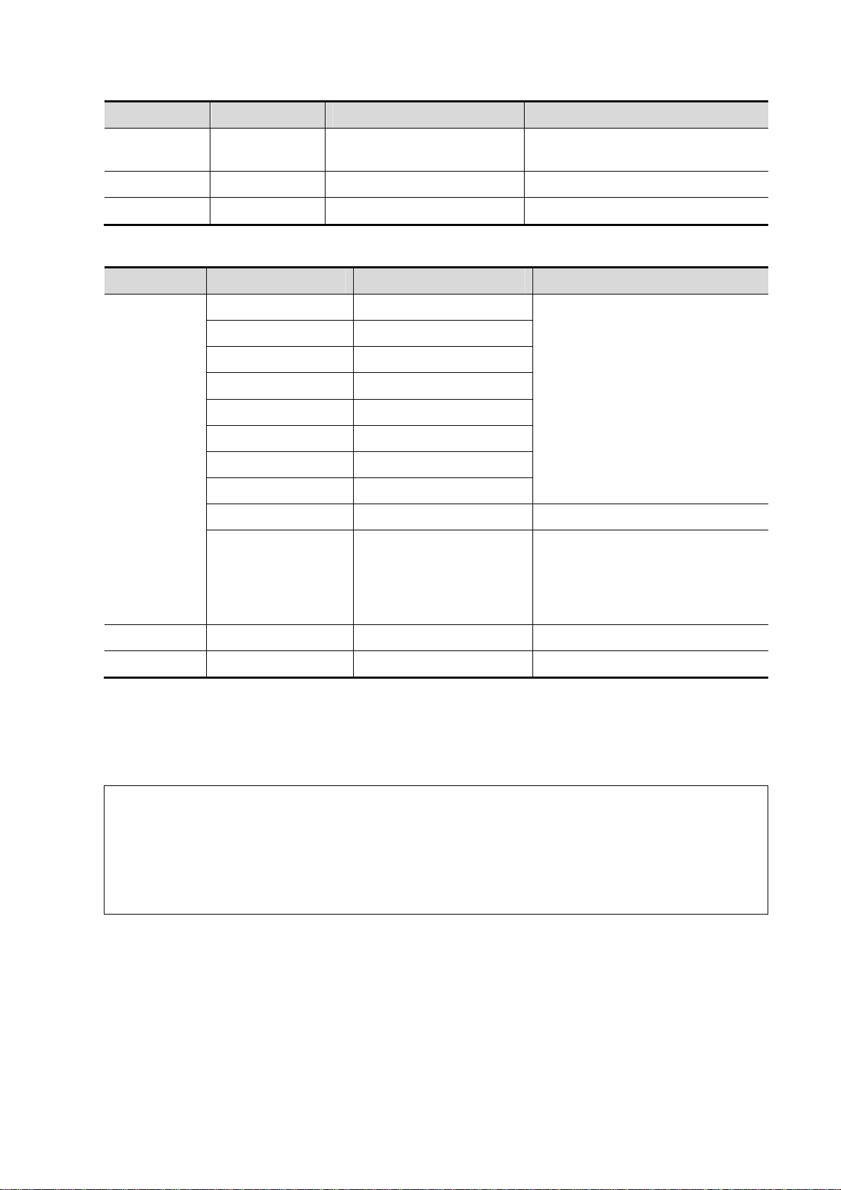
Types Tools Descriptions Methods or formulae
IVSs
Calculation / /
Study / /
interventricular septal
thickness at en systole
Doppler Obstetric Measurements
Types Tools Descriptions Methods or formulae
Umb A Umbilical Artery
Placenta A Placenta Artery
Measurement
MCA Middle Cerebral Artery
Fetal Ao Fetal Aorta
Desc Aorta Descending Aorta
Ut A Uterine Artery
Ovarian A Ovarian Artery
FHR Fetal Heart Rate HR in General D measurements
Duct Veno Ductus Veno
D trace in General D
measurements
Use 3-PT method to measure peak
value of ventricular systole (S),
peak value of early diastole (D) and
minimum value of atrial contraction
(a) to acquire Duct Veno D result.
Calculation / /
Study / /
5.5 Obstetric Measurement Operations
Operations of measurement, calculation and study are described by examples.
Tips: 1. See the table in "5.4 Obstetric Measurement Tools" above for measurement tools
and methods.
2. For the definitions of measurement, calculation and study, refer to "1.3
Measurement, Calculation and Study".
3. The order of the measurement items is presettable, see "2.4.2 Application
Measurement Preset" for details.
5.5.1 Measurement Tool Operations
Take the HC measurement as an example.
1. Select the [HC] item/tool in the measurement menu.
Select measure method from the drop-down list on the right side.
2. Measure area according to the Area method in 2D General Measurements.
Measurement results, GA calculation and OB growth percentile display in the result window.
Obstetrics 5-8
Page 65

You can preset whether to display SD and EDD or not in [System Preset] -> [OB] -> [Fetal
Gestational Age].
For more details about GA, see “5.3 GA”.
5.5.2 Calculation Tool Operations
Take the HC/AC measurement as an example.
1. Select the [HC/AC] item/tool in the measurement menu.
2. Measure the HC and AC according to the Area method in 2D General Measurements.
The second measurement is activated automatically when the first one is completed. The
results display in the result window after measurement.
5.5.3 Study Tool Operations
The operation of AFI measurement is as follows.
1. Select [AFI] in the measurement menu. Enter the submenu.
2. Measure the maximum AFs of the four amniotic fluid pockets of pregnant woman, and AFI is
calculated automatically.
5.6 Multi-fetus Exam
The system allows multi-fetus (4 at most) examination.
NOTE: Ensure that the Fetus displayed in the multi-fetus measurement menu is the one on
which you are intended to perform the measurements.
Similar to the OB measurement,
1. Set the number of fetuses in [Gestations] via [Patient Info] -> [OB].
If the [Gestations] is set to a value more than 1, the [Fetus] widget displays in the OB
measurement menu, as shown in the figure below.
You can switch among [Fetus A], [Fetus B], [Fetus C]... via the widget.
2. Perform measurement to the fetus respectively.
The measurement results in the result window are marked with fetus label A, B, C...
3. In the Obstetric report, select [Fetus A], [Fetus B], [Fetus C]... to switch among results of
different fetuses.
4. In the [Obstetric Growth Curve] dialog box, select [A], [B]... on the lower part to display the
growth curves of different fetuses.
z Data of Fetus A/ Fetus B/ Fetus C...: Different symbols are used on the growth curves to
indentify measurement data of different fetuses.
z History/ current data: Symbol size is used to distinguish them, with the history data
appeared in smaller symbol.
5-9 Obstetrics
Page 66

5.7 Obstetric Exam Report
During or after a measurement, press <Report> on the Control Panel to browse the report.
See "5.6 Multi-fetus Exam" for multi-fetus exam report.
For details about report browsing, printing and exporting etc, see "1.7 Exam Report".
5.7.1 Fetal Biophysical Profile
Fetal Biophysical Profile means to first obtain a few indexes related to fetal growth through
experiment or measurement and then evaluate the hazardous situation that the fetus is facing by
grading these indexes respectively.
1. Click [Analyze] in the OB report page, the fetus Score is listed after the fetal analysis.
The scoring criteria the system provides are based on Vintzileos formula, as shown in table
below.
Fetal growth
index
FHR
FM
FBM
FT
AF
0 score 2 score
<2, or Reactive FHR
≤15bpm
≥2 fetal movements
No FBM or
duration≤30s
Limbs stretch, no
bend, fingers loose
No AF, or AF volume
<2×2cm
Reactive FHR
≥15bpm,
duration≥15s, ≥2
times
FM ≥3 times
(Continuous
movement is
deemed to 1 time)
FBM≥1 times;
duration≥30s
Limbs and spine
stretch-bend ≥1
times
One or more AF
volume > 2×2cm
Observation
time
30 minutes
30 minutes
30 minutes
/
/
Remarks
The score(s)
can be
manually
input into the
system.
Fetal scoring results criteria:
Total scores Growth condition
8-10 scores Normal, chronic asphyxia risk low
Obstetrics 5-10
Page 67

Total scores Growth condition
4-6 scores Chronic asphyxia risk suspicious
0-2 scores Chronic asphyxia risk high
2. Scores of each index as well as the total score will be appended to the report.
5.7.2 Z-Score
As FL, BPD and GA is most relevant to fetus cardiac structure, and Z-Score regression equation is
related to natural logarithm value of FL, BPD and GA variables, Z-Score of cardiac structures can
be obtained by looking in the Z-Score table, which is important in fetus cardiac growth evaluation
and intrauterine interventional therapy.
In (predicted cardiac dimension)=m*In(FL, GA or BPD)+c
Z-Score=(In(actual)-In(predicted cardiac dimension))/root MSE
Where, the unit of FL and BPD is cm, GA is week, m is multiplier, c is intercept and root MSE is
root-mean-square error, which can be obtained from the table.
1. Enter patient basic information and obstetric information in the [Patient Info] -> [OB] dialog box.
2. Measure BPD and FL.
3. Measure fetus cardiac parameters (e.g. Ao Diam).
4. Open the report to check the Z-Score result.
Tips: Z-Score study is effective for fetus of 15~40 weeks.
5.7.3 Fetal Growth Curve
Fetus growth curve means to compare the measured data of the fetus with the normal growth curve
to judge whether the fetus is in normal growth state. Data of growth curve is all sourced from Fetal
Growth Table.
1. Enter patient information and obstetric information in [Patient Info] -> [OB] dialog box.
2. Perform one or more tools of fetal growth parameters.
3. Click [Growth] in the report page. The dialog box displays the growth curve and the position of
measurement value.
5-11 Obstetrics
Page 68

Two drop-down lists above the curve display the measurement item/tool and formula of the
curve, which can be changed.
Different symbols are used on the growth curves to indentify measurement data of different
fetuses.
Current and history data of one fetus are displayed in the same symbol with the history data
appeared in smaller size.
Click the [Print] check box to determine whether to include the growth curve in the printed
report or not.
The green dotted line indicates the clinical GA on the X-axis.
Select the number and layout of the curves from [Display Mode].
1*1: one curve displays in the screen.
2*1: two curves (up/ down) display in the screen.
2*2: four curves display in the screen.
Click [Prev Page]/ [Next] to turn the growth curve pages.
4. Click [OK] to confirm the setting and exit the page.
Tips: If the patient ID is blank, clinical GA is not calculated, or the measurement value is
not valid, measurement values will not be displayed on the curve.
5.8 References
GS Rempen A., 1991
Arztliche Fragen. Biometrie in der Fruhgraviditat (i.Trimenon): 425-430.
Obstetrics 5-12
Page 69

Hansmann M, Hackelöer BJ, Staudach A
Ultraschalldiagnostik in Geburtshilfe und Gynäkologie 1985
Hellman LM, Kobayashi M, Fillisti L, et al. Growth and development of the human
fetus prior to the 20th week of gestation. Am J Obstet Gynecol 1969; 103:784-800.
Studies on Fetal Growth and Functional Developments, Takashi Okai, Department of
Obstetrics and Gynecology, Faculty of Medicine, University of Tokyo
China
Written by Zhou Yiongchang & Guo Wanxue
in Chapter 38 of "Ultrasound Medicine" (3rd edition) Science & Technology Literature
Press, 1997
Daya S, Wood S, Ward S, et al. Early pregnancy assessment with transvaginal
ultrasound scanning Can Med Assoc J, 1991;144(4);441-446
CRL Rempen A., 1991
Arztliche Fragen. Biometrie in der Fruhgraviditat (i.Trimenon): 425-430.
Hansmann M, Hackelöer BJ, Staudach A
Ultraschalldiagnostik in Geburtshilfe und Gynäkologie 1985
Hadlock FP, et al. Fetal Crown-Rump Length: Reevaluation of Relation to Menstrual
Age (5-18 weeks) with High-Resolution Real-time US. Radiology 182:501-505.
Jeanty P, Romero R. "Obstetrical Sonography", p. 56. New York, McGraw-Hill, 1984.
Nelson L. Comparison of methods for determining crown-rump measurement by
realtime ultrasound. J Clin Ultrasound February 1981; 9:67-70.
Robinson HP, Fleming JE. A critical evaluation of sonar crown rump length
measurements. Br J Obstetric and Gynaecologic September 1975; 82:702-710.
Fetal Growth Chart Using the Ultrasonotomographic Technique
Keiichi Kurachi, Mineo Aoki
Department of Obstetrics and Gynecology, Osaka University Medical School
Revision 3 (September 1983)
Studies on Fetal Growth and Functional Developments
Takashi Okai Department of Obstetrics and Gynecology, Faculty of Medicine,
University of Tokyo
Pam Loughna1, Lyn Chitty, Tony Evans, Trish Chudleigh. Fetal size and dating:Fetal
size and dating: charts recommended for clinical obstetric practice. British Medical
Ultrasound Society. ULTRASOUND August 2009 Volume 17 Number 3
China
5-13 Obstetrics
Page 70

Written by Zhou Yiongchang & Guo Wanxue
in Chapter 38 of "Ultrasound Medicine" (3rd edition) Science & Technology Literature
Press, 1997
Ultrasonic fetal Measurement Standards for an Australian Population compiled by
Susan Campbell Westerway - Faculty of Health Sciences University of Sydney
http://www.asum.com.au/open.home.htm Date: December 2003
BPD Merz E., Werner G. & Ilan E. T. “Ultrasound in Gynecology and Obstetrics” Textbook
and Atlas 312, 326-336. 1991 Georg Thieme Verlag, pp.326~327
Rempen A., 1991 Arztliche Fragen. Biometrie in der Fruhgraviditat (i.Trimenon):
425-430.
Hansmann M, Hackelöer BJ, Staudach A Ultraschalldiagnostik in Geburtshilfe und
Gynäkologie 1985
Jeanty P, Romero R. "Obstetrical Ultrasound." McGraw-Hill Book Company, 1984,
pp. 57-61.
Sabbagha RE, Hughey M. Standardization of sonar cephalometry and gestational
age. Obstetrics and Gynecology October 1978; 52:402-406.
Kurtz AB, Wapner RJ, Kurtz RJ, et al. Analysis of bipariental diameter as an accurate
indicator of gestational age. J Clin Ultrasound 1980;8:319-326.
Fetal Growth Chart Using the Ultrasonotomographic Technique, Keiichi Kurachi,
Mineo Aoki, Department of Obstetrics and Gynecology, Osaka University Medical
School Revision 3 (September 1983)
Studies on Fetal Growth and Functional Developments, Takashi Okai, Department of
Obstetrics and Gynecology, Faculty of Medicine, University of Tokyo
Chitty LS, Altman DG British Journal of Obstetrics and Gynaecology January 1994,
Vol.101 P29-135.
China
Written by Zhou Yiongchang & Guo Wanxue
in Chapter 38 of "Ultrasound Medicine" (3rd edition) Science & Technology Literature
Press, 1997
Altmann D.G.; Chitty L.S. New charts for ultrasound dating of pregnancy Obstetrics
and Gynecology Vol. 10: 174-191, 1997
Hadlock FP, et al. Estimating Fetal Age: Computer-Assisted Analysis of Multiple Fetal
Growth Parameters. Radiology 1984:152: 497-501
Hansmann, Hackeloer, Staudach, Wittmann. Ultrasound Diagnosis in Obstetrics and
Gynecology. Springer-Verlag, New York, 1985
Obstetrics 5-14
Page 71

Jeanty P., Cousaert E., Hobbins J.C., Tack B., Bracken M., Cantraine F. A longitudinal
Study of fetal head biometry. American Journal of Perinatology; Volume1; Number 2;
January 1984; pages 118-128
R. J. M. Snijders and K. H. Niicolaides. Fetal biometry at 14-40 weeks’gestation.
Ultrasound Obstet. Gynecol. 4 (1994) 34-48
Norio Shinozuka, Takashi Okai, Masahiko Mizuno. Issued by Shindan & Tiryo Sya
Tokyo University, School of Medicine, OB/GYN dept. How to interpret OB/GYN
ultrasound measurement data. 80. Fetal Measurement Obstetrics & Gynecology
Chapter 56 Separate volume; 1989, Oct. 27th Publication
OFD Merz E., Werner G. & Ilan E. T., 1991
Ultrasound in Gynecology and Obstetrics Textbook and Atlas 312, 326-336.
Hansmann M, Hackelöer BJ, Staudach A
Ultraschalldiagnostik in Geburtshilfe und Gynäkologie 1985
Ultrasonic fetal Measurement Standards for an Australian Population. compiled by
Susan Campbell Westerway - Faculty of Health Sciences University of Sydney
http://www.asum.com.au/open.home.htm Date: December 2003
Hansmann, Hackelöer, Staudach, (Wittmann). Ultrasound Diagnosis in Obstetrics
and Gynecology. Springer- Verlag, New York, 1986,p.433
R. J. M. Snijders and K. H. Niicolaides. Fetal biometry at 14-40 weeks’gestation.
Ultrasound Obstet. Gynecol. 4 (1994) 34-48
HC Merz E., Werner G. & Ilan E. T., 1991
Ultrasound in Gynecology and Obstetrics Textbook and Atlas 312, 326-336.
Jeanty P, Romero R. "Obstetrical Ultrasound." McGraw-Hill Book Company, 1984.
Hansmann M, Hackelöer BJ, Staudach A
Ultraschalldiagnostik in Geburtshilfe und Gynäkologie 1985
Chitty LS, Altman DG
British Journal of Obstetrics and Gynaecology January 1994, Vol.101
P29-135.
Ultrasonic fetal Measurement Standards for an Australian Population. compiled by
Susan Campbell Westerway - Faculty of Health Sciences University of Sydney
http://www.asum.com.au/open.home.htm Date: December 2003
R. J. M. Snijders and K. H. Niicolaides. Fetal biometry at 14-40 weeks’ gestation.
Ultrasound Obstet. Gynecol. 4 (1994) 34-48
AC Merz E., Werner G. & Ilan E. T., 1991
Ultrasound in Gynecology and Obstetrics Textbook and Atlas 312, Georg Thieme
5-15 Obstetrics
Page 72

Verlag,326-336.
Jeanty P, Romero R. A longitudinal study of fetal abdominal growth, "Obstetrical
Ultrasound." MacGraw-Hill Book Company, 1984.
Chitty LS, Altman DG
British Journal of Obstetrics and Gynaecology January 1994, Vol.101
P29-135.
Ultrasonic fetal Measurement Standards for an Australian Population. compiled by
Susan Campbell Westerway - Faculty of Health Sciences University of Sydney
http://www.asum.com.au/open.home.htm Date: December 2003"
Crequat,J., Duyme,M., Brodaty,G. Biometry 2000. Fetal growth charts by the French
College of fetal ultrasonography and the Inserm U 155. Gynecol.Obstet Fertil., Vol.
28 No. 2, 2000, pages 435-455
Chitty L.S. Altman D.G. Hendesson A. Campell S. Charts of fetal size: 3. Abdominal
measurements. Br J Obstetric Gynaecology 1994, Vol 101, pages 35-43.
Chitty ,L.S., Altman,D.G., Henderson,A., Campbell,S. Charts of fetal size: 3.
Abdominal measurements Br.J.Obstet.Gynaecol. Vol. 101 No. 2, 1994, pages
125-131
Hansmann, Hackeloer, Staudach, Wittmann. Ultrasound Diagnosis in Obstetrics and
Gynecology Springer- Verlag, New York, 1986, p.431.
Jeanty P., Cousaert E., Cantraine F. Normal Growth of the Abdominal Perimeter.
American Journal of Perinatology; Volume 1 Number 2; January 1984; pages
129-135
R. J. M. Snijders and K. H. Niicolaides. Fetal biometry at 14-40 weeks’ gestation.
Ultrasound Obstet. Gynecol. 4 (1994) 34-48
FL Merz E., Werner G. & Ilan E. T., 1991
Ultrasound in Gynaecology and Obstetrics Textbook and Atlas 312, 326-336.
Hadlock FP, et al. Estimating Fetal Age: Computer-Assisted Analysis of Multiple Fetal
Growth Parameters. Radiology 1984; 152 (No. 2):499.
Hansmann M, Hackelöer BJ, Staudach A
Ultraschalldiagnostik in Geburtshilfe und Gynäkologie 1995
Warda A. H., Deter R. L. & Rossavik, I. K., 1985.
Fetal femur length: a critical re-evaluation of the relationship to menstrual age.
Obstetrics and Gynaecology, 66,69-75.
O'Brien GD, Queenan JT (1981)
Growth of the ultrasound femur length during normal pregnancy,
American Journal of Obstetrics and Gynecology 141:833-837.
Jeanty P, Rodesch F, Delbeke D, Dumont J. Estimation of gestational age from
measurements of fetal long bones. Journal of Ultrasound Medicine
Obstetrics 5-16
Page 73

February 1984; 3:75-79.
Hohler C., Quetel T. Fetal femur length: equations for computer calculation of
gestational age from ultrasound measurements. American Journal of Obstetrics and
Gynecology June 15, 1982; 143 (No. 4):479-481.
Keiichi Kurachi, Mineo Aoki
Department of Obstetrics and Gynecology, Osaka University Medical School
Revision 3 (September 1983)
Studies on Fetal Growth and Functional Developments
Takashi Okai Department of Obstetrics and Gynecology, Faculty of Medicine,
University of Tokyo
Chitty LS, Altman DG
British Journal of Obstetrics and Gynaecology January 1994, Vol.101
P29-135.
Jeanty P., Rodesch F., Delbeke D., Dumont J. “Estimation of Gestational Age from
Measurements of Fetal Long Bones” Journal of Ultrasound Medicine, 3: 75-79, February,
1984
China
Written by Zhou Yiongchang & Guo Wanxue in Chapter 38 of "Ultrasound Medicine"
(3rd edition) Science & Technology Literature Press, 1997
ASUM
Ultrasonic fetal Measurement Standards for an Australian Populati on, com piled by Su sa n
Campbell Westerway - Faculty of Health Sciences University of Sydney.
http://www.asum.com.au/open/home.htm Date: December 2003
R. J. M. Snijders and K. H. Niicolaides; Fetal biometry at 14-40 weeks’ gestation
Ultrasound Obstet. Gynecol. 4 (1994) 34-48
TAD Merz E., Werner G. & Ilan E. T., 1991
Ultrasound in Gynaecology and Obstetrics Textbook and Atlas 312, 326-336.
APAD Merz E., Werner G. & Ilan E. T., 1991
Ultrasound in Gynecology and Obstetrics Textbook and Atlas 312, 326-336.
THD Hansmann M, Hackelöer BJ, Staudach A
Ultraschalldiagnostik in Geburtshilfe und Gynäkologie 1985
FTA Fetal Growth Chart Using the Ultrasonotomographic Technique
Keiichi Kurachi, Mineo Aoki
Department of Obstetrics and Gynecology, Osaka University Medical School
Revision 3 (September 1983)
5-17 Obstetrics
Page 74

HUM Merz E., Werner G. & Ilan E. T., 1991
Ultrasound in Gynaecology and Obstetrics Textbook and Atlas 312, 326-336.
Jeanty P, Rodesch F, Delbeke D, Dumont J. Estimation of gestational age from
measurements of fetal long bones. Journal of Ultrasound Medicine February 1984;
3:75-79.
Ultrasonic fetal Measurement Standards for an Australian Populati on, com piled by Su sa n
Campbell Westerway - Faculty of Health Sciences University of Sydney.
http://www.asum.com.au/open/home.htm Date: December 2003
CLAV “Clavicular Measurement: A New Biometric Parameter for
Fetal Evaluation.” Journal of Ultrasound in Medicine 4:467-470, September 1985.
TCD Goldstein I, et al. Cerebellar measurements with ultrasonography in the evaluation of
fetal growth and development. Am J Obstet Gynecol 1987; 156:1065-1069.
Hill LM, et al. Transverse cerebellar diameter in estimating gestational age in the
large for gestational age fetus, Obstet Gynecol 1990; 75:981-985.
R. J. M. Snijders and K. H. Niicolaides; Fetal biometry at 14-40 weeks’ gestation
Ultrasound Obstet. Gynecol. 4 (1994) 34-48
Ulna Merz E., Werner G. & Ilan E. T., 1991
Ultrasound in Gynaecology and Obstetrics Textbook and Atlas 312, 326-336.
Tibia Merz E., Werner G. & Ilan E. T., 1991
Ultrasound in Gynaecology and Obstetrics Textbook and Atlas 312, 326-336.
RAD Merz E., Werner G. & Ilan E. T., 1991
Ultrasound in Gynecology and Obstetrics Textbook and Atlas 312, 326-336.
Fetal Limb Bimetry (Letter), Radiology 147:602, 1983
FIB Merz E., Werner G. & Ilan E. T., 1991
Ultrasound in Gynaecology and Obstetrics Textbook and Atlas 312, 326-336.
Fetal Limb Bimetry (Letter), Radiology 147:602, 1983
OOD
Jeanty P, Cantraine R
,
Cousaert E,et al. The Binocular Distance:A New Way to
Estimate Fetal Age. J Ultrasound Med 1984; 3: 241-243.
Ultrasou
Hadlock,Radiology,1984 152:497-501
nd GA
Hadlock
(BPD,
Hadlock FP, et al. Estimating Fetal Age: Computer-Assisted Analysis of Multiple Fetal
Growth Parameters. Radiology 1984:152: 497-501.
HC, AC
and FL)
Obstetrics 5-18
Page 75

Cist
Magna
R. J. M. Snijders and K. H. Niicolaides. Fetal biometry at 14-40 weeks’ gestation.
Ultrasound Obstet. Gynecol. 4 (1994) 34-48
Estimated Fetal Weight (EFW)
Merz E., Werner G. & Ilan E. T., Ultrasound in Gynaecology and Obstetrics. Textbook and Atlas
1991 Georg Thieme Verlag, 308-338
Hansmann M, Hackelöer BJ, Staudach A Ultraschalldiagnostik in Geburtshilfe und Gynäkologie
1995
Campbell S, Wilkin D. "Ultrasonic Measurement of Fetal Abdomen Circumference in the Estimation
of Fetal Weight." Br J Obstetrics and Gynaecology September 1975; 82 (No. 9):689-697.
Hadlock F, Harrist R, et al. Estimation of fetal weight with the use of head, body, and femur
measurements - a prospective study. American Journal of Obstetrics and Gynecology February 1,
1985; 151 (No. 3):333-337.
Shepard M, Richards V, Berkowitz R, Warsof S, Hobbins J. An Evaluation of Two Equations for
Predicting Fetal Weight by Ultrasound. American Journal of Obstetrics and Gynecology January
1982; 142 (No. 1): 47-54.
Fetal Growth Chart Using the Ultrasonotomographic Technique Keiichi Kurachi, Mineo Aoki
Department of Obstetrics and Gynecology, Osaka University Medical School Revision 3
(September 1983)
Studies on Fetal Growth and Functional Developments Takashi Okai Department of Obstetrics and
Gynecology, Faculty of Medicine, University of Tokyo
Brenner W.E., Edelman D.A., Hendricks C.H. A standard of fetal growth for the United States of
America. VOL. 91, NO. 6, JUNE 1998
,
Hadlock FP
Radiology 1991;181:129-133
Ronald Williams, Robert Creasy, George Cunningham, Warren Hawes, Rank Norris, Michiko
Tashiro. Fetal Growth and Perinatal Viability in California. Obstetric & Gynecology Vol. 59, NO. 5,
May 1982
Hansmann, Hackeloer, Staudach, Wittmann. Ultrasound Diagnosis in Obstetrics and Gynecology.
Springer-Verlag, New York, 1986
Shinozuka N., Okai T., Kohzuma S., Mukubo M., Shih C.T., Maeda T., et al. Formulas for Fetal
Weight Estimation by Ultrasound Measurements based on Neonatal Specific Gravities and
Volumes. American Journal of Obstetrics and Gynecology 157: 1140-1145; 1987
Harrist R, Martinez-Poyer J. In utero analysis of fetal growth: A sonographic standard.
Fetal Biophysical Profile
Manning FA. Dynamic ultrasound-based fetal assessment: the fetal biophysical profile score.
Women's Hospital, Department of Obstetrics and Gynecology, Winnipeg, Manitoba, Canada.
5-19 Obstetrics
Page 76

Dyanamic ultrasound-based fetal Assessment: The Fetal Biophysical Profile Score,Clinical obstetrics
and gynecology,Manning FA,38:26-44,1995a.
Weight Percentile for Age
Hadlock FP,Harrist R, Martinez-Poyer J. In utero analysis of fetal growth: A sonographic standard.
Radiology 1991;181:129-133.
AFI
Thomas R,Moore MD, Jonathan E, Cayle MD. The amniotic fluid index in normal human pregnancy.
American journal of Obstetrics and Gynecology May 1990; 162: 1168-1173.
Z-Score
Schneider C. et. al., “Development of Z-scores for fetal cardiac dimensions from
echocardio-graphy”, Ultrasound Obstet Gynecol. Vol. 26, 2005: 599-605.
CI
Hadlock, F., Deter, R., Carpenter, R., Park, D. Estimating Fetal Age: effect of Head Shape on BPD.
American Journal of Roentgenology, 137: 83-85, July 1981
FL/AC
Hadlock F., Deter R., Harrist R., Roecker E., Park S. A Date-Independent Predictor of Intrauerine
Growth Retardation: Femur Length/Abdominal Circumference Ratio American Journal of
Roentgenology, 141:979-984, November 1983
FL/HC(Hadlock)
Hadlock,F.P.,Harrist,R.B.,Shah,Y.,Park,S.K. The femur length/head circumference relation in
obstetric sonography. J Ultrasound Med 1984, 3: 439-442 (Fetal Growth)
HC/AC(Campbell)
Campbell S. Ultrasound Measurement of Fetal Head and Abdomen Circumference Ratio in the
Assessment of Growth Retardation. Obstetrics and Gynaecology, Vol 84, 165- 174, March 1977
FL/BPD
Hohler C.W., Quetel, T:A: Comparison of Ultrasound Femur Length and Biparietal Diameter in Late
pregnancy. American Journal of Obstetrics and Gynecology, volume 14, No. 7: 759-762,
1-Dec.-1981
Ut A RI/MCA RI
Kurmanavicius J, Florio I, Wisser J, Hebisch G, Zimmermann R, Muller R et al. Reference
resistance indices of the umbilical, fetal middle cerebral and uterine arteries at 24-42 weeks of
gestation. Ultrasound Obstet. Gynecol. 1997;10:112-20.
Obstetrics 5-20
Page 77

Duct Veno
A. A. BASCHAT. Relationship between placental blood flow resistance and precordial venous
Doppler indices. Ultrasound Obstet Gynecol 2003; 22: 561–566
5-21 Obstetrics
Page 78

Page 79

6 Cardiology
6.1 Cardiac Exam Preparations
Make the following preparations before measurement:
1. Confirm that the current probe is appropriate.
2. Check if the current date of the system is correct.
3. Press <Patient>, input patient information in [Patient Info] -> [CARD] page.
For more details, refer to "Exam Preparation -> Patient Information" in the Operator's Manual
[Basic Volume].
4. Switch to the correct exam mode.
6.2 Basic Cardiac Measurement Procedures
1. Press <Patient>, input patient information in [Patient Info] -> [CARD] page.
2. Press <Measure> to enter the Application Measurement.
3. Select measurement tool in the menu to start the measurement.
See the table in "6.3 Cardiac Measurement Tools" for measurement tools.
See section "6.4 Cardiac Measurement Operations" and steps in "3 General Measurement" for
measurement methods.
4. Press <Report> to view the exam report, see "6.5 Cardiac Exam Report" for details.
6.3 Cardiac Measurement Tools
The system supports the following cardiac measurements:
NOTE: 1. Measurement tools mentioned below are configured in the system. The application
measurement packages provided in this system are generally different
combinations of measurement tools. For more information about package preset,
see "2.4.2 Application Measurement Preset".
2. The heartbeat of the traced spectrum in HR measurement should equal to that is
preset, otherwise the obtained HR (Heart Rate) is incorrect. See "2.2 Measurement
Parameters" for relevant preset.
3. Some application items in the measurement preset library (and matching list in
result assignment) are displayed different from that in the measurement menu and
result window.
In preset library (and matching list in result assignment), the item is followed with
the word indicating the mode or location. Such as LA Diam (2D) means that the item
is measured during 2D mode; LA Diam(LA Vol A-L) means that the item is contained
in a study named LV Vol(A-L).
6-1 Cardiology
Page 80

6.3.1 2D Cardiac Measurements
Types Tools Descriptions Methods or formulae
LA Diam Left Atrium Diameter
LA Major Left Atrium major Diameter
LA Minor Left Atrium minor Diameter
RA Major Right Atrium major Diameter
Measurement
RA Minor Right Atrium minor Diameter
LV Major Left Ventricular major Diameter
LV Minor Left Ventricular minor Diameter
RV Major
RV Minor
LA Area Left Atrium area
RA Area Right Atrium area
LV Area(d)
LV Area(s)
RV Area(d)
RV Area(s)
LVID d
Right Ventricular major
Diameter
Right Ventricular minor
Diameter
Left Ventricular area at
end-diastole
Left Ventricular area at
end-systole
Right Ventricular area at
end-diastole
Right Ventricular area at
end-systole
Left Ventricular Internal
Diameter at end-diastole
Distance in 2D General
Measurements
Area in 2D General
Measurements
LVID s
RVDd
RVDs
LVPWd
LVPWs
RVAWd
RVAWs
IVSd
Left Ventricular Internal
Diameter at end-systole
Right Ventricular Diameter at
end-diastole
Right Ventricular Diameter at
end-systole
Left Ventricular Posterior wall
thickness at end-diastole
Left Ventricular Posterior wall
thickness at end-systole
Right Ventricular Anterior wall
thickness at end-diastole
Right Ventricular Anterior wall
thickness at end-systole
Interventricular Septal
thickness at end-diastole
Distance in 2D General
Measurements
Cardiology 6-2
Page 81

Types Tools Descriptions Methods or formulae
IVSs
Ao Diam Aorta Diameter
Ao Arch Diam Aorta arch Diameter
Ao Asc Diam Ascending Aorta Diameter
Ao Desc Diam Descending Aorta Diameter
Ao Isthmus Aorta Isthmus Diameter
Ao st junct Aorta ST junct Diameter
Ao Sinus Diam Aorta Sinus Diameter
Duct Art Diam Ductus Arteriosus Diameter
Pre Ductal Previous ductal Diameter
Post Ductal Posterior ductal Diameter
ACS Aortic Valve Cusp Separation
LVOT Diam
AV Diam Aorta Valve Diameter
AVA Ao rtic Valv e Area
Interventricular Septal
thickness at end-systole
Left Ventricular Outflow Tract
Diameter
Distance in 2D General
Measurements
Area in 2D General
Measurements
Measurement
PV Diam Pulmonary valve Diameter
LPA Diam Left pulmonary Artery Diameter
RPA Diam
MPA Diam
RVOT Diam
MV Diam Mitral Valve diameter
MVA Mitral Valve area
MCS Mitral Valve Cusp Separation
EPSS
TV Diam Tricuspid valve Diameter
TVA Tricuspid Valve Area
IVC Diam(Insp)
IVC Diam(Expir)
Right pulmonary Artery
Diameter
Main pulmonary Artery
Diameter
Right Ventricular Outflow Tract
Diameter
Distance between point E and
Interventricular Septum when
mitral valve is fully open
Inferior vena cava inspiration
Diameter
Inferior vena cava expiration
Diameter
Distance in 2D General
Measurements
Area in 2D General
Measurements
Distance in 2D General
Measurements
Area in 2D General
Measurements
Distance in 2D General
Measurements
6-3 Cardiology
Page 82

Types Tools Descriptions Methods or formulae
Measurement
SVC Diam(Insp)
SVC
Diam(Expir)
LCA Left Coronary Artery
RCA Right Coronary Artery
VSD Diam
ASD Diam Atrial Septal defect Diameter
PDA Diam
PFO Diam Patent Oval Foramen Diameter
PEd Pericardial Effusion at diastole
PEs Pericardial Effusion at systole
HR Heart Rate
Diastole
Systole
Superior vena cava inspiration
Diameter
Superior vena cava expiration
Diameter
Ventricular Septal defect
Diameter
Patent ductus Arteriosus
Diameter
End-diastolic Left Ventricular
Measurement
End-systolic Left Ventricular
Measurement
Distance in 2D General
Measurements
Heart Rate in M General
Measurements
FoldLine in 2D mode
LA/Ao
Calculation
Ao/LA
Study See below
Left Atrium Diameter/Aorta
Diameter
Aorta Diameter/Left Atrium
Diameter
LA Diam (cm) / Ao Diam
(cm)
Ao Diam (cm) / LA Diam
(cm)
6.3.2 M Cardiac Measurements
Typ es Tools Descriptions Methods or formulae
LA Diam Left Atrium Diameter
LVIDd
LVIDs
Measurement
RVDd
RVDs
Left Ventricular Internal
Diameter at end-diastole
Left Ventricular Internal
Diameter at end-systole
Right Ventricular Diameter at
end-diastole
Right Ventricular Diameter at
end-systole
Distance in M General
Measurements
Cardiology 6-4
LVPWd
Left Ventricular Posterior wall
thickness at end-diastole
Page 83

Typ es Tools Descriptions Methods or formulae
LVPWs
RVAWd
RVAWs
IVSd
IVSs
Ao Diam Aorta Diameter
Ao Arch Diam Aorta arch Diameter
Ao Asc Diam Ascending Aorta Diameter
Ao Desc Diam Descending Aorta Diameter
Ao Isthmus Aorta Isthmus Diameter
Ao st junct Aorta ST junct Diameter
Ao Sinus Diam Aorta Sinus Diameter
LVOT Diam
Left Ventricular Posterior wall
thickness at end-systole
Right Ventricular Anterior wall
thickness at end-diastole
Right Ventricular Anterior wall
thickness at end-systole
Interventricular Septal
thickness at end-diastole
Interventricular Septal
thickness at end-systole
Left Ventricular outflow tract
Diameter
ACS Aortic valve Cusp Separation
LPA Diam Left pulmonary Artery Diameter
RPA Diam
MPA Diam
RVOT Diam
MV E Amp
MV A Amp
MV E-F Slope Mitral Valve E-F slope
MV D-E Slope Mitral Valve D-E slope
MV DE
MCS Mitral Valve Cusp Separation
EPSS
Right pulmonary Artery
Diameter
Main pulmonary Artery
Diameter
Right Ventricular outflow tract
Diameter
Amplitude of the Mitral Valve E
wave
Amplitude of the Mitral Valve A
wave
Amplitude of the Mitral Valve
DE wave
Distance between point E and
the interventricular septum
Slope in M General
Measurements
Distance in M General
Measurements
PEd Pericardial effusion at diastole
PEs Pericardial effusion at systole
6-5 Cardiology
Page 84

Typ es Tools Descriptions Methods or formulae
LVPEP
LVET Left Ventricular ejection time
RVPEP
RVET Right Ventricular ejection time
HR Heart Rate
Diastole
Systole
LA/Ao
Calculation
Ao/LA
Study See below
Left Ventricular pre-ejection
period
Right Ventricular pre-ejection
period
End-diastolic Left Ventricular
Measurement
End-systolic Left Ventricular
Measurement
Left Atrium diameter/Aorta
diameter
Aorta Diameter/Left Atrium
Diameter
6.3.3 Doppler Cardiac Measurements
Time in 2D General
Measurements
Heart Rate in M General
Measurements
FoldLine in 2D mode
LA Diam (cm) / Ao Diam
(cm)
Ao Diam (cm) / LA Diam
(cm)
Types Tools Descriptions Methods or formulae
Mitral Valve Maximum
Velocity
Mitral Valve E-wave
Velocity-Time Integral
Mitral Valve A-wave
Velocity-Time Integral
Mitral Valve Velocity-Time
Integral
Mitral Valve Acceleration
Time
Mitral Valve Deceleration
Time
Isovelocity Compression
Time
D Vel in Doppler General
Measurements
D Trace in Doppler General
Measurements
Acceleration in Doppler
General Measurements
Time in Doppler General
Measurements
Measurement
MV Vmax
MV E Vel Mitral Valve E-wave Velocity
MV A Vel Mitral Valve A-wave Velocity
MV E VTI
MV A VTI
MV VTI
MV AccT
MV DecT
IVRT Isovelocity Relaxation Time
IVCT
MV E Dur Mitral Valve E-wave Duration
Cardiology 6-6
MV A Dur Mitral Valve A-wave Duration
LVOT Vmax
Left Ventricular Outflow Tract
Velocity
D Vel in Doppler General
Measurements
Page 85

Types Tools Descriptions Methods or formulae
LVOT VTI
LVOT AccT
AAo Vmax
DAo Vmax
AV Vm ax
AV VT I
LVPEP
LVET Left Ventricular Ejection Time
AV Ac cT
AV De cT
Left Ventricular Outflow Tract
Velocity-Time Integral
Left Ventricular Outflow Tract
Acceleration Time
Ascending Aorta Maximum
Velocity
Descending Aorta Maximum
Velocity
Aorta Valve Maximum
Velocity
Aorta Valve Velocity-Time
Integral
Left Ventricular Pre-ejection
Period
Aorta Valve Acceleration
Time
Aorta Valve Deceleration
Time
D trace in Doppler General
measurements
Time in Doppler General
Measurements
D Vel in Doppler General
Measurements
D trace in Doppler General
measurements
Time in Doppler General
Measurements
Measurement
RVET
RVPEP
TV Vmax
TV E Vel
TV A Vel
TV VTI
TV AccT
TV DecT
TV A Dur
RVOT Vmax
Right Ventricular Ejection
Time
Right Ventricular Pre-ejection
Period
Tricuspid Valve Maximum
Velocity
Tricuspid Valve E-wave Flow
Velocity
Tricuspid Valve A-wave Flow
Velocity
Tricuspid Valve Velocity-Time
Integral
Tricuspid Valve Acceleration
Time
Tricuspid Valve Deceleration
Time
Tricuspid Valve A-wave
Duration
Right Ventricular Outflow
Tract Maximum Velocity
D Vel in Doppler General
Measurements
D trace in Doppler General
measurements
Acceleration in Doppler
General Measurements
Time in Doppler General
Measurements
D Vel in Doppler General
Measurements
RVOT VTI
PV Vmax
Right Ventricular Outflow
Tract Velocity-Time Integral
Pulmonary Valve Maximum
Velocity
D trace in Doppler General
measurements
D Vel in Doppler General
Measurements
6-7 Cardiology
Page 86

Types Tools Descriptions Methods or formulae
PV VTI
PV AccT
MPA Vmax
RPA Vmax
LPA Vmax
PVein S Vel
PVein D Vel
PVein A Vel
PVein A Dur
PVein S VTI
PVein D VTI
Pulmonary Valve
Velocity-Time Integral
Pulmonary Valve
Acceleration Time
Main Pulmonary Artery
Maximum Velocity
Right Pulmonary Artery
Maximum Velocity
Left Pulmonary Artery
Maximum Velocity
Pulmonary Vein S-wave Flow
Velocity
Pulmonary Vein D-wave Flow
Velocity
Pulmonary Vein A-wave Flow
Velocity
Pulmonary Vein A-wave
Duration
Pulmonary Vein S-wave
Velocity-time Integral
Pulmonary Vein D-wave
Velocity-time Integral
D trace in Doppler General
measurements
Acceleration in Doppler
General Measurements
D Vel in Doppler General
Measurements
Time in Doppler General
Measurements
D trace in Doppler General
measurements
PVein DecT
IVC Vel (Insp)
IVC Vel (Expir)
SVC Vel (Insp)
SVC Vel (Expir)
MR Vmax
MR VTI
MS Vmax
dP/dt Rate of Pressure change dP/dt Measurement
AR Vmax
Pulmonary Vein Deceleration
Time
Inferior Vena Cava
Inspiration Maximum Velocity
Inferior Vena Cava Expiration
Maximum Velocity
Superior Vena Cava
Inspiration Maximum Velocity
Superior Vena Cava
Expiration Maximum Velocity
Mitral Valve Regurgitation
Maximum Velocity
Mitral Valve Regurgitation
Velocity-Time Integral
Mitral Valve Stenosis
Maximum Velocity
Aortic Valve Regurgitation
Maximum Velocity
Time in Doppler General
measurements
D Vel in Doppler General
Measurements
D trace in Doppler General
measurements
D Vel in Doppler General
Measurements
D Vel in Doppler General
Measurements
Cardiology 6-8
AR VTI
Aortic Valve Regurgitation
Velocity-Time Integral
D trace in Doppler General
measurements
Page 87

Types Tools Descriptions Methods or formulae
AR DecT
AR PHT
AR Ved
TR Vmax
TR VTI
PR Vmax
PR VTI
PR PHT
PR Ved
Aortic Valve Regurgitation
Deceleration Time
Aortic Valve Regurgitation
Pressure Half Time
Aortic Valve Regurgitation
Velocity at end-Diastole
Tricuspid Valve Regurgitation
Maximum Velocity
Tricuspid Valve Regurgitation
Velocity-Time Integral
Pulmonary Valve
Regurgitation Maximum
Velocity
Pulmonary Valve
Regurgitation Velocity-Time
Integral
Pulmonary Valve
Regurgitation Pressure Half
Time
Pulmonary Valve
Regurgitation Velocity at
end-Diastole
Acceleration in Doppler
General Measurements
Doppler measurement
D Vel in Doppler General
Measurements
D trace in Doppler General
measurements
D Vel in Doppler General
Measurements
D trace in Doppler General
measurements
Doppler Measurement
Calculation
VSD Vmax
ASD Vmax
PDA Vel(d)
PDA Vel(s)
Ventricular Septal Defect
Maximum Velocity
Atrial Septal Defect
Maximum Velocity
Patent Ductus Arteriosus
Velocity at End-diastole
Patent Ductus Arteriosus
Velocity at End-systole
D Vel in Doppler General
Measurements
Coarc Pre-Duct Coarctation of Pre-Ductus
Coarc Post-Duct Coarctation of Post-Ductus
HR Heart Rate
Select from the pop-up
RAP Right Atrium Pressure
dialog box or input a value
manually. See RAP
measurement in “RVSP”
MV E/A Mitral Valve E-Vel/A-Vel
MVA(PHT)
Mitral Valve Orifice Area
(PHT)
MV E Vel (cm/s) / MV A Vel
(cm/s)
2
MVA(PHT) (cm
) = 220 / MV
PHT (ms)
TV E/A Tricuspid Valve E-Vel/A-Vel
TVA(PHT)
Tricuspid Valve Orifice Area
(PHT)
6-9 Cardiology
Page 88

Types Tools Descriptions Methods or formulae
Study See below
6.3.4 TDI Cardiac Measurements
The following measurement items are performed in TDI mode.
Types Tools Descriptions Methods or formulae
Ea(medial) Mitral Valve medial Early diastolic motion
Aa(medial) Mitral Valve medial Late diastolic motion
Sa(medial) Mitral Valve medial Systolic motion
ARa(medial) Mitral Valve medial Acceleration Rate
D Vel in Doppler
General
Measurements
Measurement
Calculation / /
Study See below
DRa(medial) Mitral Valve medial Deceleration Rate
Ea(lateral) Mitral Valve lateral Early diastolic motion
Aa(lateral) Mitral Valve lateral Late diastolic motion
Sa(lateral) Mitral Valve lateral Systolic motion
ARa(lateral) Mitral Valve lateral Acceleration Rate
DRa(lateral) Mitral Valve lateral Deceleration Rate
D Vel in Doppler
General
Measurements
6.4 Cardiac Measurement Operations
Tips: 1. See the table in "6.3 Cardiac Measurement Tools" above for measurement tools and
methods.
2. For the definitions of measurement, calculation and study, refer to "1.3 Measurement,
Calculation and Study".
3. The order of the measurement items is presettable, see "2.4.2 Application
Measurement Preset" for details.
4. Measurements of some tools described in this Chapter are to be performed in several
imaging modes, please select appropriate imaging modes in measurement.
6.4.1 Measurement Tool Operations
1. Select the item/tool in the measurement menu.
2. Perform the measurement referring to methods in table above.
6.4.2 Calculation Tool Operations
1. Select the item/tool in the measurement menu.
2. The system calculates and displays the results after relating measurement items have been
completed.
Cardiology 6-10
Page 89

6.4.3 Study Tool Operations
6.4.3.1 Left Ventricular Function
This group of studies is to estimates the Left Ventricular (LV) diastolic and systolic capabilities by a
series of clinical indices measured on B or M image. Except for calculating left ventricular volume
and end diastole and end systole, they may calculate the following indices (not all indices are
calculated in every study, see Study Results table in each study for reference).
Result Descriptions Formulae
SV Stroke Volume SV(ml) = EDV(ml)-ESV(ml)
CO Cardiac Output CO(l/min) = SV(ml)×HR(bpm)/ 1000
EF Ejection Fraction EF(No unit) = SV(ml)/ EDV(ml)
SI SV Index SI(No unit) = SV(ml)/ Body Surface Area (m2)
CI Cardiac output CI(No unit) = CO(l/min)/Body Surface Area (m2)
FS
MVCF
NOTE: The HR value inputted manually should be within the range of 1~999.
Fractional
Shortening
Mean Velocity of
Circumferential
Fiber Shortening
FS (No unit) = (LVIDd (cm) – LVIDs [cm]) / LVIDd (cm)
MVCF = (LVIDd(cm) – LVIDs(cm)) / (LVIDd (cm) × ET (s) )
S-P Ellipse
Study Items
Tools Descriptions Operations
LVLd apical
LVAd apical
LVLs apical
LVAs apical
Left Ventricular Long-axis Length at
End-diastole in apical view
Left Ventricular Long-axis Area at
End-diastole in apical view
Left Ventricular Long-axis Length at
End-systole in apical view
Left Ventricular Long-axis Area at
end-systole in apical view
Distance in 2D General
Measurements
Area in 2D General
Measurements
Distance in 2D General
Measurements
Area in 2D General
Measurements
HR Heart Rate Type in
Study Results
Tools Descriptions Formulae
EDV(SP Ellipse)
ESV(SP Ellipse)
End-diastolic Left
Ventricular Volume
End-systolic Left
Ventricular Volume
8
=)(Ellipse) EDV(SP
ml ×
3
π
8
=)(Ellipse) ESV(SP
ml ×
3
π
22
)(apical LVAd
cm
)(apical LVLd
cm
22
)(apical LVAs
cm
)(apical LVLs
cm
6-11 Cardiology
Page 90

Tools Descriptions Formulae
SV(SP Ellipse) Stroke Volume
CO(SP Ellipse) Cardiac Output
EF(SP Ellipse) Ejection Fraction
SI(SP Ellipse) SV Index
CI(SP Ellipse) CO Index
Operating Procedures
1. Select [S-P Ellipse] in the measurement menu.
2. In apical long-axis view at end-diastole, measure the following parameters:
LVLd apical
LVAd apical
EDV value is then calculated.
3. In apical long-axis view at end-systole, measure the following parameters:
LVLs apical
LVAs apical
ESV value is then calculated.
The system calculates SV and EF;
If height and weight have been input already, SI is calculated.
4. Type in HR (heart rate).
The CO and CI are calculated automatically.
See table in “6.4.3.1 Left Ventricular Function”
B-P Ellipse
Study Items
Tools Descriptions Operations
LVID d
LVIDs Left Ventricular Internal Diameter at End-systole
LVAd s ax MV
LVAs s ax MV
LVAd apical
LVAs apical
HR Heart Rate Type in
Study Results
Tools Descriptions Formulae
EDV(BP Ellipse)
Left Ventricular Internal Diameter at
End-diastole
Left Ventricular Area at Mitral Valve level at
End-diastole in Short-axis view
Left Ventricular Area at Mitral Valve level at
End-systole in Short-axis view
Left Ventricular Long-axis Area at End-diastole
in apical view
Left Ventricular Long-axis Area at end-systole in
apical view
End-diastolic Left
Ventricular Volume
*1
Distance in 2D General
Measurements
Area in 2D General
Measurements
Cardiology 6-12
Page 91

Tools Descriptions Formulae
ESV(BP Ellipse)
SV(BP Ellipse) Stroke Volume
CO(BP Ellipse) Cardiac Output
EF(BP Ellipse) Ejection Fraction
SI(BP Ellipse) SV Index
CI(BP Ellipse) CO Index
*1 means:
*2 means:
Operating Procedures
1. Select [B-P Ellipse] in the menu.
2. In left ventricular short-axis view, measure the following parameters:
At end diastole: LVIDd
At end systole: LVIDs
3. In short-axis view at mitral valve level, measure the following parameters:
At end diastole: LVAd sax MV
At end systole: LVAs sax MV
4. In apical long-axis view, measure the following parameters:
LVAd apical, the EDV is calculated
LVAs apical, the ESV is calculated
The system calculates SV and EF after LVAs apical has been measured;
If height and weight have been input already, SI is calculated.
5. Type in HR (heart rate).
The CO and CI are calculated automatically.
End-systolic Left
Ventricular Volume
8
)( Ellipse)EDV(BP
=
3
π
8
)( Ellipse)ESV(BP
=
3
π
*2
See table in “6.4.3.1 Left Ventricular
Function”
22
22
)()(sax MV LVAd)(apical LVAd
cmLVIDdcmcmml ××
)()(sax MV LVAs)(apical LVAs
cmLVIDscmcmml ××
Bullet
Study Items
Tools Descriptions Operations
LVLd apical
LVLs apical
LVAd s ax MV
LVAs s ax MV
Left Ventricular Long-axis Length at
End-diastole in apical view
Left Ventricular Long-axis Length at
End-systole in apical view
Left Ventricular Area at Mitral Valve level at
End-diastole in Short-axis view
Left Ventricular Area at Mitral Valve level at
End-systole in Short-axis view
Distance in 2D General
Measurements
Area in 2D General
Measurements
6-13 Cardiology
Page 92

Tools Descriptions Operations
HR Heart Rate Type in
Study Results
Tools Descriptions Formulae
EDV(Bullet)
ESV(Bullet)
End-diastolic Left
Ventricular Volume
End-systolic Left
Ventricular Volume
EDV(ml)= 5/6×LVLd apical(cm)×LVAd sa x MV(c m
ESV(ml)= 5/6×LVLs apical(cm)×LVAs s a x MV(c m
SV(Bullet) Stroke Volume
CO(Bullet) Cardiac Output
EF(Bullet) Ejection Fraction
See table in "6.4.3.1 Left Ventricular Function"
SI(Bullet) SV Index
CI(Bullet) CO Index
Operating Procedures
1. Select [Bullet] in the measurement menu.
2. In apical long-axis view, measure the following parameters:
At end diastole: LVLd apical
At end systole: LVLs apical.
3. In short-axis view at mitral valve level, measure the following parameters:
At end diastole: LVAd sax MV, the EDV is calculated
At end systole: LVAs sax MV, the ESV is calculated
The system calculates SV and EF; If height and weight have been input already, SI is
calculated.
4. Type in HR (heart rate).
The CO and CI are calculated automatically.
2
)
2
)
Mod.Simpson
Study Items
Tools Descriptions Operations
LVLd apical
LVLs apical
LVAd s ax MV
LVAs s ax MV
LVAd s ax PM
Left Ventricular Long-axis Length at End-diastole in
apical view
Left Ventricular Long-axis Length at End-systole in
apical view
Left Ventricular Area at Mitral Valve level at
End-diastole in Short-axis view
Left Ventricular Area at Mitral Valve level at
End-systole in Short-axis view
Left Ventricular Area at Papillary Muscle level at
end-diastole in short axis view
Distance in 2D General
Measurements
Area in 2D General
Measurements
Cardiology 6-14
Page 93

Tools Descriptions Operations
LVAs sax PM
Left Ventricular Area at Papillary Muscle level at
end-systole in short axis view
HR Heart Rate Type in
Study Results
Tools Descriptions Formulae
EDV(Mod.Simpson) End-diastolic Left Ventricular Volume *1
ESV(Mod.Simpson) End-systolic Left Ventricular Volume *2
SV(Mod.Simpson) Stroke Volume
CO(Mod.Simpson) Cardiac Output
EF(Mod.Simpson) Ejection Fraction
See table in "6.4.3.1 Left
Ventricular Function”
SI(Mod.Simpson) SV Index
CI(Mod.Simpson) CO Index
*1 means:
⎛
cm
][apical LVLd
⎜
mLEDV
][
9
×=
⎜
⎝
cm
2
×+×
LVAd2][ MV saxLVAd4
×+
222
cmcmcm
*2 means:
⎛
cm
][apical LVLs
mLESV
][
9
⎜
×=
⎜
⎝
cm
2
×+×
LVAs2][ MV saxLVAs4
×+
cmcmcm
Operating Procedures
1. Select [Mod.Simpson] in the measurement menu.
2. In apical long-axis view, measure the following parameters:
At end diastole: LVLd apical
At end systole: LVLs apical
3. In short-axis view at mitral valve level, measure the following parameters:
At end diastole: LVAd sax MV
At end systole: LVAs sax MV
4. In short-axis view at papillary muscle level, measure the following parameters:
At end diastole: LVAd sax PM, the EDV is calculated
At end systole: LVAs sax PM, the ESV is calculated
The system calculates SV and EF;
If height and weight have been input already, SI is calculated.
5. Type in HR (heart rate).
The CO and CI are calculated automatically.
⎞
⎟
⎟
][PM saxLVAd][ MV saxLVAd][ PM sax
⎠
⎞
⎟
222
⎟
][PM saxLVAs][ MV saxLVAs][ PM sax
⎠
Simpson SP
This method includes two studies: Simp SP(A4C) and Simp SP(A2C).
6-15 Cardiology
Page 94

Study Items
Tools Descriptions Operations
EDV(A2C/A4C)
ESV(A2C/A4C)
HR Heart Rate Type in
Study Results
Tools Descriptions Formulae
EDV(Simp SP)
ESV(Simp SP)
End-diastolic Left Ventricular Volume
(apical 2-chamber/ 4-chamber)
End-systolic Left Ventricular Volume
(apical 2-chamber/ 4-chamber)
=)(EDV
ml
End-diastolic Left
Ventricular Volume
LVLd apical: Left Ventricular Long-axis Length at
End-diastole in apical view, i.e. the long-axis length
obtained in measurement.
r
i
: Radiuses obtained from diastolic measurement
ml
=)(ESV
End-systolic Left
Ventricular Volume
LVLs apical: Left Ventricular Long-axis Length at
End-systole in apical view, i.e. the long-axis length
obtained in measurement.
Simpson measurement (Trace/
Spline/ Auto)
20
)(apical LVLd
cm
cm
××
∑
i
i
=
1
20
)(apical LVLs
2
××
∑
i
1
i
=
π
20
π
20
2
)(
cmr
)(
cmr
r
i
: Radiuses obtained from systolic measurement
SV Stroke Volume
CO Cardiac Output
EF Ejection Fraction
See table in “6.4.3.1 Left Ventricular Function“
SI SV Index
CI CO Index
Operating Procedures
1. Select [Simp SP] in the measurement menu.
2. Measure the endocardium.
Measure the left ventricular endocardium at end-diastolic, and set the long axis, the EDV is
obtained;
Measure the left ventricular endocardium at end-systolic, and set the long axis, the ESV is
obtained;
The system calculates SV and EF;
If height and weight have been input already, SI is calculated.
3. Type in HR (heart rate).
The CO and CI are calculated automatically.
Measurement Methods
The endocardium can be measured using the following methods.
z Trace
Cardiology 6-16
Page 95

Trace the endocardium along the edge of the target area using the method similar to the
“Trace“ method in 2D Area measurements; and then set the long axis.
z Spline
Set reference points (up to 12) along the edge of the endocardium using the method similar to
the “Spline” method in 2D Area measurements; and then set the long axis.
z Auto
(1) Set point A and B using the trackball and <Set> key, where in,
h A: Left ventricular interventricular septal and mitral valve junction;
h B: Left ventricular wall and mitral valve junction;
(2) After setting A and B, the cursor positions automatically at point D where is considered as
the apical part by system detecting, also the long axis (line segment CD) and the line that
traces the endocardium are displayed at the same time. Where in,
h C: Midpoint of A and B.
h D: Apical part of left ventricle.
You can:
z Adjust the long axis
a) Rotate the trackball to position the cursor on the long axis (which turns yellow), and
then press <Set>;
b) Rotate the trackball, adjust the point D (with point C unchanged) after the cursor
changes to .
z Adjust the trace line
a) Rotate the trackball to position the cursor on the trace line (which turns yellow), and
then press <Set>;
b) Rotate the trackball, move the cursor along the endocardium edge to adjust the line
after the cursor changes to (with ABD points unchanged).
D
A
C
B
Press <Set> outside the line to confirm the adjustment.
Simpson BP
Study Items
Tools Descriptions Operations
EDV(A2C)
End-diastolic Left Ventricular
Volume (apical 2-chamber)
Simpson measurement (Trace/ Spline)
ESV(A2C)
End-systolic Left Ventricular
Volume (apical 2-chamber)
See “Simpson SP” for endocardium
measurement
EDV(A4C)
End-diastolic Left Ventricular
Volume (apical 4-chamber)
6-17 Cardiology
Page 96

Tools Descriptions Operations
ESV(A4C)
End-systolic Left Ventricular
Volume (apical 4-chamber)
HR Heart Rate Type in
Study Results
Tools Descriptions Formulae
EDV(Simpson BP) End-diastolic Left Ventricular Volume
ESV(Simpson BP) End-systolic Left Ventricular Volume
SV(Simpson BP) Stroke Volume
CO(Simpson BP) Cardiac Output
EF(Simpson BP) Ejection Fraction
SI(Simpson BP) SV Index
CI(Simpson BP) CO Index
*1 means:
ml
)(EDV
=
π
{}
cmLVLdcmLVLdMAX
42
ii
*2 means:
ml
)(ESV
=
π
{}
cmLVLscmLVLsMAX
ii
42
Calculate the LV volume on the apical 2-chamber view image:
)(
cmLVLd
2
ml
)(2ESV
mlπ=
=)(2EDV
π
i
20
)(
cmLVLs
i
2
20
Calculate the LV volume on the apical 4-chamber view image:
)(
cmLVLd
i
)(4EDV
mlπ=
)(4ESV
mlπ=
4
20
)(
cmLVLs
i
4
20
Where,
LVLd
– Left ventricular long-axis length at end diastole at apical two-chamber view, which is
i
2
the long-axis length obtained by EDV(A2C) measurement
LVLd
– Left ventricular long-axis length at end diastole at apical four-chamber view, which is
i
4
the long-axis length obtained by EDV(A4C) measurement
LVLs
– Left ventricular long-axis length at end systole at apical two-chamber view, which is
i
2
the long-axis length obtained by ESV(A2C) measurement
LVLs
– Left ventricular long-axis length at end systole at apical four-chamber view, which is
i
4
the long-axis length obtained by ESV(A4C) measurement
*1
*2
See table in “6.4.3.1 Left
Ventricular Function”
20
20
∑
∑
i
∑
∑
20
∑
1
=
i
20
∑
=
i
1
20
2
cmr
2
i
1
=
i
20
2
cmr
i
2
1
=
20
2
cmr
i
4
=
i
1
20
2
cmr
i
4
=
i
1
×××
×××
42
)(
)(
)(
)(
))()((
cmrcmr
42
ii
))()((
cmrcmr
ii
)(),(
)(),(
××
××
××
××
Cardiology 6-18
Page 97

– Radiuses obtained by EDV(A2C) or ESV(A2C) at apical two-chamber view
ir2
– Radiuses obtained by EDV(A4C) or ESV(A4C) at apical four-chamber view
ir4
CAUTION:
When using Simpson BP to measure LV function, be sure to keep
the apical four-chamber view and apical two-chamber view
perpendicular. Otherwise the measurement result will be incorrect.
Operating Procedures
1. Select [Simpson BP] in the measurement menu.
2. In apical two-chamber view, measure the following parameters:
Left ventricular endocardium at end-diastolic, and set the long axis, the EDV(A2C) is obtained;
Left ventricular endocardium at end-systolic, and set the long axis, the ESV(A2C) is obtained;
3. In apical four-chamber view, measure the following parameters:
Left ventricular endocardium at end-diastolic, and set the long axis, the EDV(A4C) is obtained;
Left ventricular endocardium at end-systolic, and set the long axis, the ESV(A4C) is obtained;
If height and weight have been input already, SV, EF and SI are calculated.
4. Type in HR (heart rate).
The CO and CI are calculated automatically.
Cube
Study Items
Tools Descriptions Operations
Diastole
Systole
LVID d
LVID s
End-diastolic Left Ventricular
Measurement
End-systolic Left Ventricular
Measurement
Left Ventricular Internal Diameter at
End-diastole
Left Ventricular Internal Diameter at
End-systole
FoldLine in 2D mode
Parallel method in M mode
Distance in 2D/M General
Measurements
HR Heart Rate Type in, or measured manully
Study Results
Tools Descriptions Formulae
IVSd
LVID d
LVPWd
Interventricular Septal Thickness at
End-diastole
Left Ventricular Internal Diameter at
End-diastole
Left Ventricular Posterior Wall Thickness at
End-diastole
Distance in 2D/M General
Measurements
IVSs
Interventricular Septal Thickness at
End-systole
6-19 Cardiology
Page 98

Tools Descriptions Formulae
LVID s
LVPWs
EDV(Cube) End-diastolic Left Ventricular Volume EDV(ml)= LVIDd(cm)3
ESV(Cube) End-systolic Left Ventricular Volume ESV(ml)= LVIDs(cm)3
SV(Cube) Stroke Volume
CO(Cube) Cardiac Output
EF(Cube) Ejection Fraction
FS(Cube) Fractional Shortening
MVCF(Cube)
SI(Cube) SV Index
CI(Cube) CO Index
Operating Procedures
1. Select [Cube] in the measurement menu.
2. Measure Diastole in 2D or M mode.
The IVSd, LVIDd. LVPWd and EDV are obtained.
3. Measure Systole in 2D or M mode.
IVSs, LVSs, LVIDs, LVPWs and ESV are obtained.
The system calculates SV, EF and FS;
4. Type in HR (heart rate) or measure HR value in M mode.
If height and weight have been input already, SI, CO and CI are calculated.
MVCF is calculated if LVET is measured.
In [Preset]-> [System Preset]-> [Application] screen, you can set the method for
Cube/Teichholz/Gibson study.
Left Ventricular Internal Diameter at
End-systole
Left Ventricular Posterior Wall Thickness at
End-systole
Mean Velocity of Circumferential Fiber
Shortening
See table in “6.4.3.1 Left
Ventricular Function”
Teichholz
Study Items
Tools Descriptions Operations
Diastole
Systole
LVID d
LVID s
HR Heart Rate Type in, or measured manually
Cardiology 6-20
End-diastolic Left Ventricular
Measurement
End-systolic Left Ventricular
Measurement
Left Ventricular Internal Diameter
at End-diastole
Left Ventricular Internal Diameter
at End-systole
FoldLine in 2D mode
Parallel method in M mode
Distance in 2D/M General Measurements
Page 99

Study Results
Tools Descriptions Formulae
IVSd
LVID d
LVPWd
IVSs
LVID s
LVPWs
EDV(Teichholz)
ESV(Teichholz)
Interventricular Septal Thickness
at End-diastole
Left Ventricular Internal Diameter
at End-diastole
Left Ventricular Posterior Wall
Thickness at End-diastole
Interventricular Septal Thickness
at End-systole
Left Ventricular Internal Diameter
at End-systole
Left Ventricular Posterior Wall
Thickness at End-systole
End-diastolic Left Ventricular
Volume
End-systolic Left Ventricular
Volume
SV(Teichholz) Stroke Volume
CO(Teichholz) Cardiac Output
EF(Teichholz) Ejection Fraction
Distance in 2D/M General
Measurements
EDV(ml)=(7×(LVIDd(cm))
(cm))
ESV(ml)=(7×(LVIDs(cm))
cm))
3
)/(2.4+LVIDd
3
)/(2.4+LVIDs(
FS(Teichholz) Fractional Shortening
MVCF(Teichholz)
Mean Velocity of Circumferential
Fiber Shortening
See table in “6.4.3.1 Left Ventricular
Function”
SI(Teichholz) SV Index
CI(Teichholz) CO Index
Operating Procedures
See table above for methods and formulae of the measurement items.
See section "Cube" for measurement procedures.
In [Preset]-> [System Preset]-> [Application] screen, you can set the method for
Cube/Teichholz/Gibson study.
Gibson
Study Items
Tools Descriptions Operations
Diastole
Systole
End-diastolic Left Ventricular
Measurement
End-systolic Left Ventricular
Measurement
FoldLine in 2D mode
Parallel method in M mode
LVID d
Left Ventricular Internal Diameter
at End-diastole
Distance in 2D/M General Measurements
6-21 Cardiology
Page 100

Tools Descriptions Operations
π
π
LVID s
Left Ventricular Internal Diameter
at End-systole
HR Heart Rate Type in, or measured manually
Study Results
Tools Descriptions Formulae
IVSd
LVID d
LVPWd
Interventricular Septal
Thickness at End-diastole
Left Ventricular Internal
Diameter at End-diastole
Left Ventricular Posterior Wall
Thickness at End-diastole
Distance in 2D/M General Measurements
IVSs
LVID s
LVPWs
EDV(Gibson)
Interventricular Septal
Thickness at End-systole
Left Ventricular Internal
Diameter at End-systole
Left Ventricular Posterior Wall
Thickness at End-systole
End-diastolic Left Ventricular
Volume
)(EDV cmLVIDdcmLVIDdml ×+××
=
6
2
)()90.5)(98.0(
ESV(Gibson)
End-systolic Left Ventricular
Volume
)(ESV cmLVIDscmLVIDsml ×+××
=
6
SV(Gibson) Stroke Volume
CO(Gibson) Cardiac Output
EF(Gibson) Ejection Fraction
SI(Gibson) SV Index
CI(Gibson) CO Index
See table in “6.4.3.1 Left Ventricular
Function”
Mean Velocity of
MVCF(Gibson)
Circumferential Fiber
Shortening
FS(Gibson) Fractional Shortening
Operating Procedures
See table above for methods and formulae of the measurement items.
See section "Cube " for measurement procedures.
6.4.3.2 Left Ventricular Mass (LV Mass)
2
)()18.4)(14.1(
Estimates the Index of Left Ventricular Mass (LV Mass-I) by calculating the LV Mass.
LV MASS-I (No unit) = LV Mass (g) / Body Surface Area (m
2
)
Cardiology 6-22
 Loading...