

Page 1

DC-8/DC-8 PRO/DC-8 CV/DC-8 EXP/DC-8S
Diagnostic Ultrasound System
Service Manual
Revision 19.0
Page 2

Page 3

Table of Content
Table of Content................................................................................................................... i
Revision History ................................................................ ................................ .................. I
Intellectual Property Statement ........................................................................................ III
Applicable for..................................................................................................................... III
Statement ........................................................................................................................... III
Responsibility on the Manufacturer Party ....................................................................... IV
Customer Service Department .......................................................................................... IV
1 Safety Precautions.................................................................................................... 1-1
1.1 Meaning of Signal Words ................................................................................................. 1-1
1.2 Symbols .......................................................................................................................... 1-1
1.2.1 Meaning of Safety Symbols ...................................................................................... 1-1
1.2.2 Warning Labels ........................................................................................................ 1-2
1.2.3 General Symbols ..................................................................................................... 1-2
1.3 Safety Precautions .......................................................................................................... 1-3
1.3.1 Electric safety .......................................................................................................... 1-4
1.3.2 Mechanical safety .................................................................................................... 1-4
1.3.3 Personnel Safety ...................................................................................................... 1-5
1.3.4 Other ....................................................................................................................... 1-5
2 Specifications ........................................................................................................... 2-1
2.1 Overview ......................................................................................................................... 2-1
2.1.1 Intended Use ........................................................................................................... 2-1
2.1.2 Introduction of Each Unit .......................................................................................... 2-1
2.1.3 Peripherals Supported ........................................................................................... 2-13
2.2 Specifications ................................................................................................................ 2-13
2.2.1 Dimensions & Weight ............................................................................................. 2-13
2.2.2 Electrical Specifications .......................................................................................... 2-13
2.2.3 Environmental Conditions....................................................................................... 2-14
2.2.4 Monitor Specification .............................................................................................. 2-14
3 System Installation ................................................................................................... 3-1
3.1 Preparations for Installation ............................................................................................. 3-1
3.1.1 Electrical Requirements ........................................................................................... 3-1
3.1.2 Installation Conditions ................................................................................................ 3-2
3.1.3 Confirmation before Installation ................................................................................ 3-3
3.2 Unpacking ....................................................................................................................... 3-3
3.2.1 Unpacking ................................................................................................................ 3-3
3.2.2 Notice of Packing ..................................................................................................... 3-5
3.2.3 Checking.................................................................................................................. 3-6
3.3 Installation of Main Unit ................................................................................................... 3-6
3.3.1 Open up the Monitor ................................ ................................................................ 3-6
3.3.2 Connecting the Power Cord ..................................................................................... 3-6
3.3.3 Connecting ECG ...................................................................................................... 3-7
3.3.4 Install Endocavity probe bracket ............................................................................... 3-7
3.3.5 Connecting the Transducer ...................................................................................... 3-8
3.4 Installing Peripherals ................................ ................................................................ ....... 3-8
i
Page 4

3.4.1 Connecting the Footswitch ....................................................................................... 3-8
3.4.2 Installing a Graph / Laser Printer .............................................................................. 3-9
3.4.3 Installing Video Printer ............................................................................................. 3-9
3.4.4 Installing Barcode Scanner ...................................................................................... 3-11
3.5 System Configuration .................................................................................................... 3-13
3.5.1 Running the System ............................................................................................... 3-13
3.5.2 Enter into DOPPLER ................................................................ .............................. 3-13
3.5.3 System Preset ....................................................................................................... 3-13
3.5.4 Print Preset ............................................................................................................ 3-14
3.5.5 Network Preset ...................................................................................................... 3-16
3.5.6 DICOM Preset......................................................................................................... 3-17
3.5.7 Check System Information ..................................................................................... 3-19
4 Product Principle ...................................................................................................... 4-1
4.1 General Structure of Hardware System ............................................................................ 4-1
4.2 Ultrasound Front-end Unit ............................................................................................... 4-2
4.2.1 Probe Board............................................................................................................. 4-3
4.2.2 CW Board ................................ ................................................................ ................ 4-4
4.2.3 Transmission Board ................................................................................................. 4-4
4.2.4 Receiving Board....................................................................................................... 4-5
4.2.5 Signal Processing Board .......................................................................................... 4-5
4.2.6 Front-end Analog Mother Board ............................................................................... 4-7
4.2.7 Communication Mother Board .................................................................................. 4-8
4.3 Ultrasound Back-end Unit ................................................................................................ 4-9
4.3.1 Digital Board ............................................................................................................ 4-9
4.3.2 DVR Board ............................................................................................................. 4-11
4.3.3 IO BOX Board ........................................................................................................ 4-12
4.3.4 4D or 4D&TEE board ............................................................................................. 4-13
4.3.5 Back-end Motherboard Connection ........................................................................ 4-13
4.3.6 Ultrasound System Monitoring................................................................................ 4-14
4.3.7 Indicators on the Ultrasound System ................................ ...................................... 4-15
4.4 Control Panel Unit ......................................................................................................... 4-15
4.5 ECG&PCG Unit ............................................................................................................. 4-16
4.6 Main Monitor Unit .......................................................................................................... 4-16
4.7 Touch Screen Unit ......................................................................................................... 4-18
4.8 Power Supply Unit ......................................................................................................... 4-18
4.8.1 Connecting Board .................................................................................................. 4-19
4.8.2 AC-DC Power Board .............................................................................................. 4-20
4.8.3 Back-end Power Board .......................................................................................... 4-21
4.8.4 Front-end Power Board .......................................................................................... 4-21
4.8.5 Power and the Supported Functions Distribution .................................................... 4-23
4.8.6 System power on control ........................................................................................ 4-25
5 Function and Performance Checking Method ........................................................ 5-1
5.1 Note ................................................................................................................................ 5-1
5.2 System Running Status ................................................................................................... 5-1
5.2.1 Running Status......................................................................................................... 5-1
5.2.2 Working Condition .................................................................................................... 5-1
5.3 General exam.................................................................................................................. 5-2
5.3.1 Check Flow .............................................................................................................. 5-2
5.3.2 Checking Content .................................................................................................... 5-2
5.4 Function Checking ............................................................................................................ 5-4
ii
Page 5

5.4.1 Checking Flow ......................................................................................................... 5-5
5.4.2 Content .................................................................................................................... 5-5
5.5 Performance Test .......................................................................................................... 5-10
5.5.1 Test Process .......................................................................................................... 5-10
5.5.2 Test Content........................................................................................................... 5-10
6 Software Installation &Maintenance ........................................................................ 6-1
6.1 Enter into Maintenance .................................................................................................... 6-1
6.2 Software Installation/Restoration ..................................................................................... 6-2
6.3 Enter into Windows ......................................................................................................... 6-2
6.4 Software maintenance ..................................................................................................... 6-3
6.4.1 Product Configuration .............................................................................................. 6-3
6.4.2 Log Maintenance ..................................................................................................... 6-3
6.4.3 Remote Desktop ...................................................................................................... 6-4
6.5 Data Backup and Storage ................................................................................................ 6-5
6.5.1 Manage Settings ...................................................................................................... 6-5
6.5.2 Patient Data Backup and Restore............................................................................. 6-6
6.6 HDD Partition .................................................................................................................. 6-6
7 Adjustments .............................................................................................................. 7-1
7.1 Monitor Adjustment .......................................................................................................... 7-1
7.1.1 Position Adjustment.................................................................................................. 7-1
7.1.2 Brightness and Contrast Adjustment ......................................................................... 7-2
7.1.3 Monitor Test ............................................................................................................. 7-3
7.1.4 Monitor Parameter Setting........................................................................................ 7-4
7.2 Touch Screen Adjustment ................................................................................................ 7-5
7.2.1 Touch Screen Brightness and Contrast Adjustment .................................................. 7-5
7.2.2 Touch Screen Calibration ......................................................................................... 7-5
7.2.3 Touch Screen Test.................................................................................................... 7-6
7.2.4 Touch Screen Setting ............................................................................................... 7-6
7.3 Control Panel Adjustment ................................................................................................ 7-6
7.4 Caster Adjustment ........................................................................................................... 7-7
8 Field Replaceable Unit .............................................................................................. 8-1
9 Structure and Assembly/Disassembly .................................................................... 9-1
9.1 Structure of the Whole System ........................................................................................ 9-1
9.2 Preparation ..................................................................................................................... 9-1
9.2.1 Tools Required ................................ ................................................................ ......... 9-1
9.2.2 Requirement for Engineers....................................................................................... 9-1
9.2.3 Assembly/Disassembly Requirements ...................................................................... 9-1
9.3 Assembly and Disassembly ............................................................................................. 9-1
9.3.1 Connecting Board .................................................................................................... 9-2
9.3.2 Remove Probe Board Assembly ............................................................................... 9-3
9.3.3 Hard Disk Assembly ................................................................................................. 9-5
9.3.4 IO BOX Board and WIFI PCBA ................................................................................ 9-7
9.3.5 CW Board, Transmission Board, Receiving Board, Signal Processing Board and 4D or
4D&TEE board ..................................................................................................................... 9-9
9.3.6 PC Module Assembly .............................................................................................. 9-11
9.3.7 DC-DC Power Module ............................................................................................ 9-15
9.3.8 AC-DC Power Board .............................................................................................. 9-16
9.3.9 Control Panel Assembly ......................................................................................... 9-17
9.3.10 Monitor Assembly ................................................................ ................................... 9-24
iii
Page 6

9.3.11 Minor Panel Assembly ................................................................ ............................ 9-26
9.3.12 Others .................................................................................................................... 9-31
10 Optional Installation/Assembly .............................................................................. 10-1
10.1 Installing Optional Software ........................................................................................... 10-1
10.2 Installing Optional Hardware .......................................................................................... 10-3
10.2.1 Front Board USB&ECG and Pencil Probe Port Assembly ....................................... 10-4
10.2.2 4D Module ........................................................................................................... 10-12
10.2.3 Elastography ........................................................................................................ 10-14
10.2.4 CW Board ............................................................................................................ 10-15
10.2.5 DVR Board .......................................................................................................... 10-15
10.2.6 Battery Assembly ................................................................................................. 10-17
10.2.7 Gel Warmer ......................................................................................................... 10-18
10.2.8 WIFI Module Update ............................................................................................ 10-18
11 System Diagnosis and Support ............................................................................. 11-1
11.1 General Status Indicator ................................................................ ................................. 11-1
11.1.1 The Status Indicators of the Control Panel ............................................................... 11-1
11.1.2 The Status Indicator of the Power on the IO Rear Board .......................................... 11-2
11.1.3 Monitor Status Indicator ........................................................................................... 11-2
11.1.4 The Status of Whole Machine .................................................................................. 11-2
11.1.5 Status Indicator of Gel Warmer ................................................................................ 11-3
11.2 Start-up Process of the Whole System ............................................................................ 11-4
11.2.1 Complete System AC Power on process ................................................................. 11-4
11.2.2 BIOS Start-up Process ............................................................................................ 11-5
11.2.3 Windows Start-up Process ...................................................................................... 11-5
11.2.4 Doppler Start-up Process ................................ ........................................................ 11-5
11.3 Warning and Abnormal Information ................................................................................. 11-7
11.3.1 Battery Alarm .......................................................................................................... 11-8
11.3.2 The Voltage of System Power Alarm........................................................................ 11-8
11.3.3 Temperature Alarm .................................................................................................. 11-8
11.3.4 Fan Alarm ............................................................................................................... 11-9
11.3.5 PHV Alarm ............................................................................................................ 11-10
11.3.6 Gel Warmer Abnormality ....................................................................................... 11-10
11.3.7 Other Alarms ......................................................................................................... 11-11
11.4 Self-test ........................................................................................................................ 11-12
11.4.1 Introduction ................................................................ ........................................... 11-12
11.4.2 Maintenance Self-test ........................................................................................... 11-12
11.4.3 User Self-test ........................................................................................................ 11-17
11.4.4 Test Report ................................ ........................................................................... 11-18
12 Care & Maintenance ................................................................................................ 12-1
12.1 Overview ....................................................................................................................... 12-1
12.1.1 Tools, Measurement Devices and Consumables..................................................... 12-1
12.1.2 Care and Maintenance Items ................................................................................. 12-1
12.2 Cleaning ........................................................................................................................ 12-3
12.2.1 Clean the System ................................................................................................... 12-3
12.2.2 Clean the Peripherals ............................................................................................. 12-6
12.3 Checking ....................................................................................................................... 12-7
12.3.1 General check ................................................................................................ ........ 12-7
12.3.2 System Function Check ......................................................................................... 12-8
12.3.3 Peripherals and Options Check .............................................................................. 12-9
iv
Page 7

12.3.4 Mechanical Safety Inspection ................................................................................. 12-9
12.3.5 Electrical Safety Inspection ................................................................................... 12-11
13 Troubleshooting of Regular Malfunctions............................................................. 13-1
13.1 Troubleshooting When System Can’t Be Powered on .................................................... 13-1
13.1.1 Module or Board Related ....................................................................................... 13-1
13.1.2 Key Points Supporting Troubleshooting .................................................................. 13-1
13.1.3 Troubleshooting When System Can’t Be Powered on ............................................. 13-1
13.2 Troubleshooting When System cannot be started up ..................................................... 13-2
13.2.1 Module or Board Related ....................................................................................... 13-2
13.2.2 Key Points Supporting Troubleshooting .................................................................. 13-2
13.2.3 Troubleshooting When System cannot be Started................................................... 13-3
13.3 Troubleshooting for Image Displaying ............................................................................ 13-3
13.3.1 Module or Board Related ....................................................................................... 13-3
13.3.2 Key Points Supporting Troubleshooting .................................................................. 13-3
13.3.3 Troubleshooting for Image Displaying ..................................................................... 13-4
13.4 Probe Socket System Related Malfunction Troubleshooting ........................................... 13-5
13.4.1 Module or Board Related ....................................................................................... 13-5
13.4.2 Key Points Supporting Troubleshooting .................................................................. 13-5
13.4.3 Probe Socket System Related Malfunction Troubleshooting ................................... 13-5
13.5 IO System Related Malfunction Troubleshooting ............................................................ 13-6
13.5.1 Module or Board Related ....................................................................................... 13-6
13.5.2 Key Points Supporting Troubleshooting .................................................................. 13-6
13.5.3 IO System Related Malfunction Troubleshooting..................................................... 13-6
13.6 Control Panel Malfunction Troubleshooting .................................................................... 13-7
13.6.1 Module or Board Related ....................................................................................... 13-7
13.6.2 Key Points Supporting Troubleshooting .................................................................. 13-8
13.6.3 Control Panel Malfunction Troubleshooting ............................................................. 13-8
13.7 LCD and Display Malfunction Troubleshooting ............................................................... 13-9
13.7.1 Module or Board Related ....................................................................................... 13-9
13.7.2 Key Points Supporting Troubleshooting .................................................................. 13-9
13.7.3 Display Related Troubleshooting ............................................................................ 13-9
13.8 ECG Module Related Troubleshooting ......................................................................... 13-10
13.8.1 Module or Board Related ..................................................................................... 13-10
13.8.2 Key Points Supporting Troubleshooting ................................................................ 13-10
13.8.3 ECG module Related Troubleshooting.................................................................. 13-10
Appendix A Electrical Safety Inspection .................................................................A-1
Appendix B Phantom Usage Illustration..................................................................B-1
Appendix C Description of Self-diagnosis Test Items ................................ ............C-1
v
Page 8

Page 9

Revision History
Revision
Date
Reason for Change
1.0
2011.11.25
Initial release
2.0
2012.2.27
1. Modify the content of “12 Preventive Maintenance” and let it more
practical.
2. Increase detailed picture and description of “6.2.1.2 Operation System
and Doppler restoration”.
3. In chapter “8 Field replaceable Unit”, replace the picture of hard disk and
change the name of “Control Panel Assembly” into “Top Cover of Keyboard
Assembly”.
4. Delete the “Reserved” description of audio and video in “1.2.3 General
Symbols”.
5. Modify several clerical errors in the initial release.
3.0
2012.4.11
1. Modify the requirement of maintenance operator in“5.1”and“12.3.5”.
2. Increase the up/down dragline adjustment method in “7.5”.
3. Increase the disassembling and assembling method of gas spring
assembly in 9.3.12.4.
4.0
2012.11.30
1. Increase the note “Calibrate the touch screen after the system software is
upgraded or recovered” in 7.2.2.
2. Increase 9.3.12.5 the disassembling and assembling method of monitor
support arm.
3. Increase C.1.21~C.1.46 self test items in Appendix C.
5.0
2013.03.12
Monitor replacement
1. Modify “4.6 Fig 4-21 Main Monitor Unit” schematic diagram.
2. Modify procedure description in 7.1.2
3. Modify monitor assembly procedure 9.3.10
6.0
2013.04.11
1. Modify installing notification for 4D mode in chapter 10.2.2(4D option
does not require DSP board since 02.00.00 version);
2. Add 2.1.3 printer model(MITSUBISHI P95DW-N, Canon selphy CP800);
3. Modify 2.1.3 footswitch model description
4. Add Appendix C.1.1 item;
5. Add Restore package checking tool 6.2.3
6. Add pencil probe cable installing method 10.2.1
7. Change HDD FRU part number (old number is to be used for SFDA
region only, add CE/FDA region number)
7.0
2013.08.20
1. Self-diagnosis test description modification
2. Chapter 10.2, 9.3.2 ECG module photo update
3. Change 11.2 windows startup picture.
8.0
2014.1.15
Add the order number and disassembly of monitor’s front cover.
9.0
2014.9.12
1. Add DC-8 EXP control panel figure in 2.1.2.4;
2. Add FRU of PC module assembly, digital board assembly, COM
module, keyboard and top cover assembly, control panel top cover
Mindray may revise this publication from time to time without written notice.
I
Page 10

and digital board assembly in 8 chapter.
3. In 9.3.6, add digital board assembly and COME module assembly
procedure for DC-8 EXP
4. 9.3.9.7 chapter add digital keyboard assembly procedure for DC-8
EXP.
5. Update appendix C self-diagnosis chapter.
6. 10.2.7 chapter updates gel warmer cable connection description.
7. 10.1 chapter adds Promote function description.
10.0
2015.3.26
1. 2.1.3 add video printer UP-X898MD and UP-D898MD, and mark the
printers that is supported only on XP operating system.
2. 3.4.3.3 Wireless printer is not supported by the DC8 series products
later than V4.0.
3. 3.5.5 update the descriptions and screen shots for wireless network
settings.
4. 3.5.7 Update the picture for Setup-About page。
5. Chapter 8: add to PC FRUs, and delete the old PC FRU used for DC8
EXP which is no longer served as FRU.
6. Add digital board FRU used on non-EXP in Win7.
7. Add Hard disk used in OS Win7 for DC-8 non-EXP and EXP in the
region of CE/FDA/India/Russia & CIS.
8. 10.1 Add picture of the screen for Promote function. Update screen
picture for uninstalling the options.
9. In section 9.3.6.2, 9.3.9.7 and 10.2.1, change the steps for DC-8 EXP
only or for non DC-8 EXP only to “for win7” and “for XP”.
11.0
2015.5
1. Section 10.2, change part number and picture of the gel warmer.
Section 10.2.7 change pictures in step of installing the gel warmer.
2. Section 11.1.5, add the status indicator of the gel warmer.
3. Section 11.3.6, add the abnormality of the gel warmer.
12.0
2016.1.4
Change the WIFI disassembly.
13.0
2016.5
Add 10.2.8 for WIFI module update; add new WIFI package part number in
10.2
14.0
2016.5
Update FRU
15.0
2016.8
Update the labels in 1.2.2
16.0
2016.11
FRU chapter
Update part number of Probe Board Assembly (spare part)
Add part number of gas spring assembly
17.0
2016.11
18.0
2017.8
Update FRU chapter.
19.0
2018.4
1. Section 2.2.4.1, change the size of main monitor
2. Section 6.6, change the HDD partition
3. FRU chapter, add 23.8 inch monitor and update part number of DSP
board.
© 2011-2018 Shenzhen Mindray Bio-medical Electronics Co., Ltd. All Rights Reserved.
II
Page 11
Intellectual Property Statement
SHENZHEN MINDRAY BIO-MEDICAL ELECTRONICS CO., LTD. (hereinafter called Mindray)
owns the intellectual property rights to this Mindray product and this manual. This manual may
referring to information protected by copyright or patents and does not convey any license under
the patent rights or copyright of Mindray, or of others.
Mindray intends to maintain the contents of this manual as confidential information. Disclosure of
the information in this manual in any manner whatsoever without the written permission of Mindray
is strictly forbidden.
Release, amendment, reproduction, distribution, rental, adaptation, translation or any other
derivative work of this manual in any manner whatsoever without the written permission of Mindray
is strictly forbidden.
, , , , , BeneView, WATO,
BeneHeart, are the trademarks, registered or otherwise, of Mindray in China and other
countries. All other trademarks that appear in this manual are used only for informational or
editorial purposes. They are the property of their respective owners.
Applicable for
This service manual is applicable for the service engineers, authorized service personnel and
service representatives of this ultrasound system.
Statement
This service manual describes the product according to the most complete configuration; some of
the content may not apply to the product you are responsible for. If you have any questions, please
contact Mindray Customer Service Department.
Do not attempt to service this equipment unless this service manual has been consulted and is
understood. Failure to do so may result in personnel injury or product damage.
III
Page 12
Responsibility on the Manufacturer
WARNING:
It is important for the hospital or organization that employs this
equipment to carry out a reasonable service/maintenance plan.
Neglect of this may result in machine breakdown or injury of human
health.
Manufacturer:
Shenzhen Mindray Bio-Medical Electronics Co., Ltd.
Address:
Mindray Building, Keji 12th Road South, High-tech industrial
park, Nanshan, Shenzhen 518057,P.R.China
Website:
www.mindray.com
E-mail Address:
service@mindray.com
Tel:
+86 755 81888998
Fax:
+86 755 26582680
Party
Mindray is responsible for the effects on safety, reliability and performance of this product, only if:
All installation operations, expansions, changes, modifications and repairs of this product are
conducted by Mindray authorized personnel;
The electrical installation of the relevant room complies with the applicable national and local
requirements;
The product is used in accordance with the instructions for use.
Mindray's obligation or liability under this warranty does not include any transportation or other
charges or liability for direct, indirect or consequential damages or delay resulting from the improper
use or application of the product or the use of parts or accessories not approved by Mindray or
repairs by people other than Mindray authorized personnel.
This warranty shall not extend to:
Any Mindray product which has been subjected to misuse, negligence or accident;
Any Mindray product from which Mindray's original serial number tag or product identification
markings have been altered or removed;
Any products of any other manufacturers.
Customer Service Department
IV
Page 13
Signal word
Meaning
DANGER
Indicates an imminently hazardous situation that, if not avoided, will
result in death or serious injury.
WARNING
Indicates a potentially hazardous situation that, if not avoided,
could result in death or serious injury.
CAUTION
Indicates a potentially hazardous situation that, if not avoided, may
result in minor or moderate injury.
NOTE
Indicates a potentially hazardous situation that, if not avoided, may result
in property damage.
Symbol
Meaning
Position
Type-BF applied part
The ultrasound transducers connected to this system are
type-BF applied parts.
The ECG module connected to this system is Type-BF
applied part.
On the right side
of I/O Panel
1 Safety Precautions
This chapter describes important issues related to safety precautions, as well as the labels and
icons on the ultrasound machine.
1.1 Meaning of Signal Words
In this operator’s manual, the signal words DANGER, WARNING, CAUTION and
NOTE are used regarding safety and other important instructions. The signal words and their
meanings are defined as follows. Please understand their meanings clearly before reading this
manual.
1.2 Symbols
The following tables provide location and information of the safety symbols and warning labels,
please read carefully.
1.2.1 Meaning of Safety Symbols
Safety Precautions 1-1
Page 14
Caution.
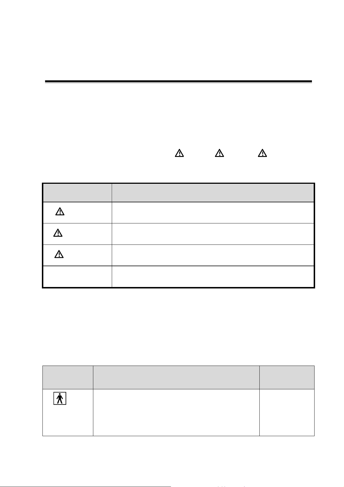
No.
Warning Labels
Meaning
1.
a. Do not place the device on a sloped surface. Otherwise
the device may slide, resulting in personal injury or the
device malfunction. Two persons are required to move the
device over a sloped surface.
b. Do not sit on the device.
c. DO NOT push the device. When the casters are locked.
d. Caution! please carefully read this manual before use
system
2.
Beware of excessive stress exerted to the device.
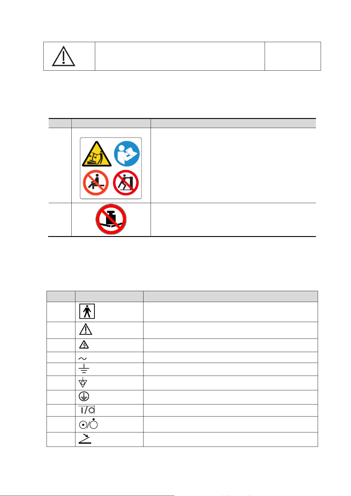
No.
Symbol
Description
1
Type-BF applied part
2
Caution
3
Dangerous voltage
4
AC (Alternating current)
5
Functional grounding
6
Equipotentiality
7
protective earth
8
Circuit breaker ON/OFF
9
Power button
10
Footswitch
a
b c d
1.2.2 Warning Labels
1.2.3 General Symbols
This system uses the symbols listed in the following table, and their meanings are explained as
well.
1-2 Safety Precautions
Page 15
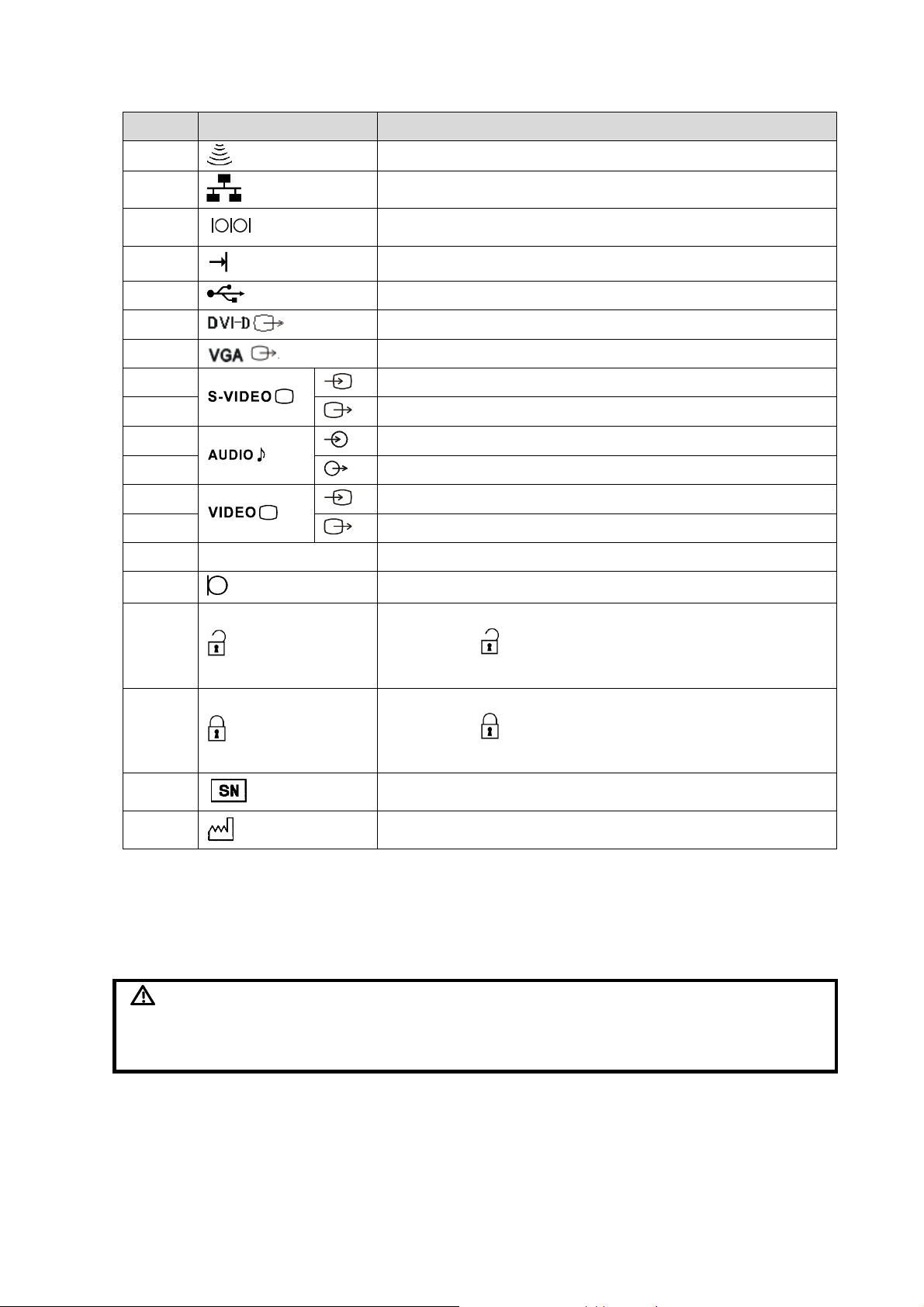
No.
Symbol
Description
11
Transducer sockets
12
Network port
14
Serial port
16
Connects the control port of the video printer
17
USB port
18
Used for DVI-D signal output.
19
Used for VGA output.
22
Reserved, used for separate video input
23
Reserved, used for separate video output
24
Reserved, used for stereo audio input.
25
Reserved, used for stereo audio output.
26
Reserved, used for composite video input
27
Reserved, used for composite video output
28
HDMI
High definition multimedia interface.
30
Microphone input jack
31
When the lever located at the bottom of the monitor support
arm points to , you can move the monitor to the right and
left.
32
When the lever located at the bottom of the monitor support
arm points to , the supporting arm is fixed at the middle
position.
33
Product serial number
34
Manufacture date
DANGER
Do not operate this system in an atmosphere containing flammable
or explosive gases such as anesthetic gases, oxygen, and
hydrogen or explosive fluid such as ethanol because an explosion
may occur.
1.3 Safety Precautions
Please read the following precautions carefully to ensure the safety of the patient and the
operator when using the probes.
Safety Precautions 1-3
Page 16

1.3.1 Electric safety
WARNING:
1.
Connect the power plug of this system and power plugs of the
peripherals to wall receptacles that meet the ratings indicated
on the rating nameplate. Using a multifunctional receptacle
may affect the system grounding performance, and cause the
leakage current to exceed safety requirements. Use the power
cord accompanied with the system provided by Mindray.
2.
Disconnect the AC power before you clean or uninstall the
ultrasound machine, otherwise, electric shock may result.
3.
In maintenance or assembly/disassembly, make sure other
cables are connected well before the battery connecting cable
is connected, otherwise the system may be damaged due to
hot-plug.
4.
Do not use this system simultaneously with equipment such
as an electrosurgical unit, high-frequency therapy equipment,
or a defibrillator, etc.; otherwise electric shock may result.
5.
This system is not water-proof. If any water is sprayed on or
into the system, electric shock may result.
CAUTION:
1.
DO NOT connect or disconnect the system’s power cord or its
accessories (e.g., a printer or a recorder) without turning OFF
the power first. This may damage the system and its
accessories or cause electric shock.
2.
Avoid electromagnetic radiation when perform performance
test on the ultrasound system.
3.
In an electrostatic sensitive environment, don’t touch the
device directly. Please wear electrostatic protecting gloves if
necessary.
4.
You should use the ECG leads provided with the ECG module.
Otherwise it may result in electric shock.
WARNING:
1.
Before moving the system, please hold the handle. If other parts
of the system are held, it may cause damage due to the
abnormal force. Do not push the system from the left/right side;
otherwise, it may be toppled over.
2.
Do not subject the transducers to knocks or drops. Use of a
defective probe may cause electric shock to the patient.
CAUTION:
1.
Fasten and fully secure any peripheral device before moving
the system, gently and carefully move the system to avoid
falling over.
1.3.2 Mechanical safety
1-4 Safety Precautions
Page 17

2.
Do not expose the system to excessive vibration (during the
transportation) to avoid device dropping, collision, or
mechanical damage.
3.
Please install the system on a flat plane with the four casters
locked. Otherwise, damage may be resulted by accidental
moving.
4.
Pay extra attention when moving the system on a sloping
ground, do not move it on a more than 10°-sloped plane to avoid
system toppling.
5.
Move the system ONLY WHEN the system is shut down or in
standby status, otherwise the system hardware disk may be
damaged.
1.3.3 Personnel Safety
NOTE:
1.
The user is not allowed to open the covers and panel of the system, neither
device disassemble is allowed.
2.
To ensure the system performance and safety, only Mindray engineers or
engineers authorized by Mindray can perform maintenance.
3.
Only technical professionals from Mindray or engineers authorized by Mindray
after training can perform maintenance.
NOTE:
For detailed operation and other information about the ultrasound system, please
refer to the operator’s manual.
1.3.4 Other
Safety Precautions 1-5
Page 18

Page 19
2 Specifications
2.1 Overview
2.1.1 Intended Use
The DC-8/DC-8 PRO/DC-8 CV/DC-8 EXP/DC-8S diagnostic ultrasound system is intended for use
in clinical ultrasonic diagnosis.
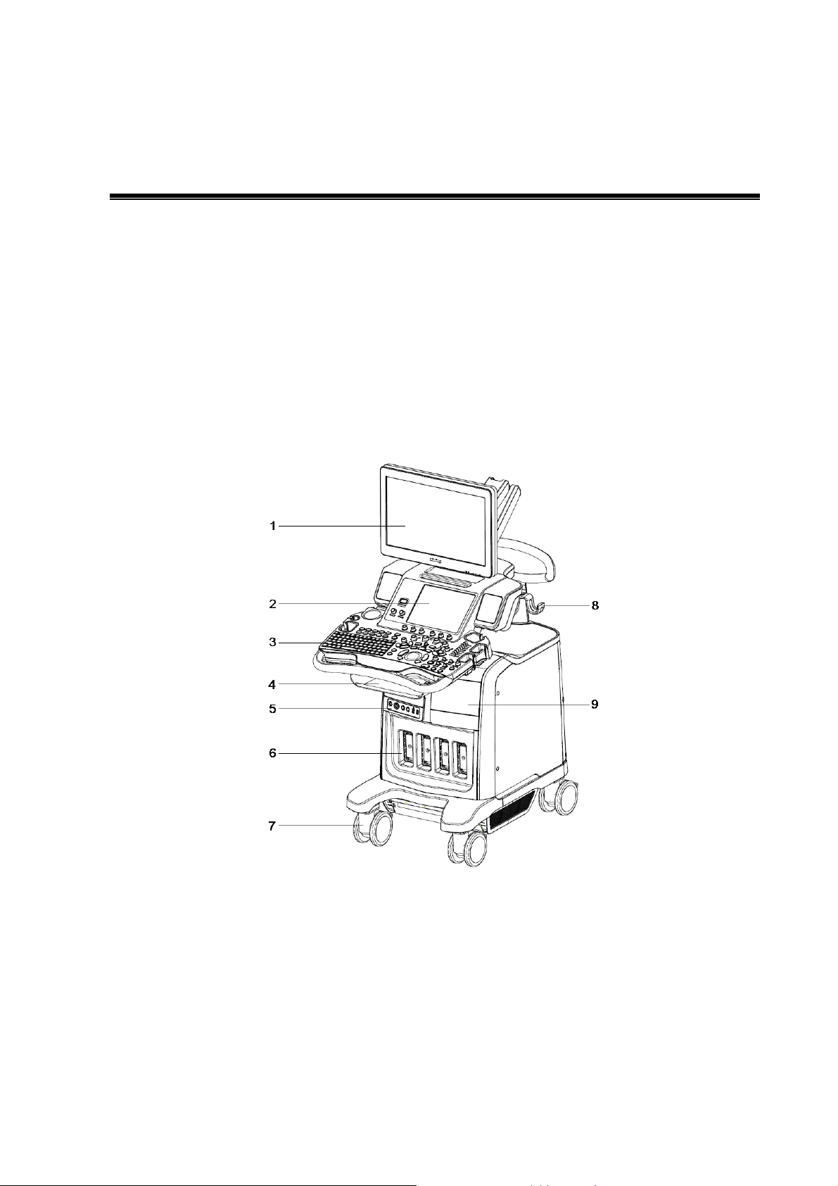
2.1.2 Introduction of Each Unit
Specifications 2-1
Page 20

No.
Name
Function
1.
Monitor
Displays the images and parameters during scanning.
2.
Touch screen panel
Operator-system interface or control.
3.
Main control panel
Operator-system interface or control.
4.
Storage compartment
Used for placing small objects.
5.
Physio panel
Used for connecting the ECG leads, PCG transducer, footswitch,
external ECG device and PCG signal etc.
6.
Probe port
Sockets connecting transducers and the main unit.
7.
Caster
Used for securing or moving the system
8.
Probe cable hook
Used for fixing the probe cable.
9.
Compartment
Used for placing B/W video printer.
10.
Monitor support arm
Supports the monitor, for adjusting the height and position of the
monitor.
11.
Rear handle
Used for pushing and moving the system.
12.
Color video printer
placing table
Used for placing the color video printer
13.
Hanger
/
14.
I/O Panel
Interface panel used for inputting and outputting signals.
15.
Power supply panel
Electrical port panel.
2-2 Specifications
Page 21
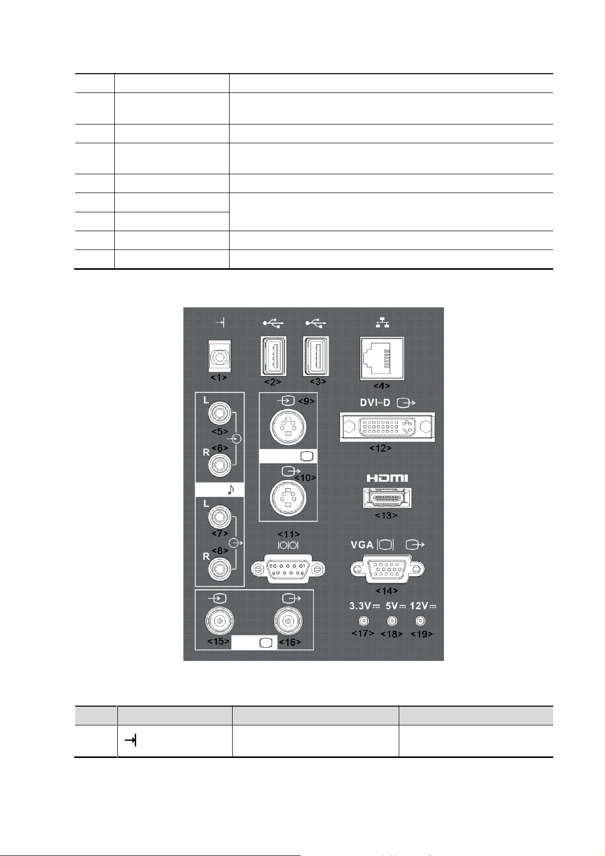
2.1.2.1 I/O panel
16.
USB_MIC port
USB port and MIC port.
17.
Endocavity probe
holder
Used for fixing the endocavity probe.
18.
DVD-RW
DVD-RW drive.
19.
Ultrasound gel holder/
gel heater
Used for placing the ultrasound gel or installing the gel heater.
20.
Pencil probe holder
Reserved.
21.
Probe holder
Used for placing general probe, endocavity probe or 4D volume
probe.
22.
Probe holder
23.
Probe holder
Used for placing general probe.
24.
Probe holder
Used for placing general probe.
No.
Symbol
Function
Property
1.
Connects the control port of the
video printer
/
Specifications 2-3
Page 22
2-4 Specifications
2.
USB ports
Support USB2.0
3.
4.
Network port
Support 10/100/1000Mbit
Ethernet
5.
Audio signal input port, left
channel.
Reserved
6.
Audio signal input port, right
channel.
Reserved
7.
Audio signal output port, left
channel.
/
8.
Audio signal output port, right
channel.
/
9.
Used for separate video input
Reserved, suppoty PAL and
NTSC.
Using standard S-Video
socket
10.
Used for separate video output.
11.
Serial port, connects the serial
port devices.
Standard serial port
12.
Used for DVI-D signal output.
DVI output resolution and
content is the same as of the
main monitor.
13.
HDMI
High definition multimedia
interface.
Standard HDMI Type A port
14.
VGA signal output.
VGA output resolution and
content is the same as of the
main monitor.
15.
Used for composite video input.
Reserved, support PAL and
NTSC。
Using standard BNC
connector.
16.
Used for composite video output.
17.
/
3.3V power indicator.
/
18.
/
5V power indicator.
/
19.
/
12V power indicator.
/
Page 23
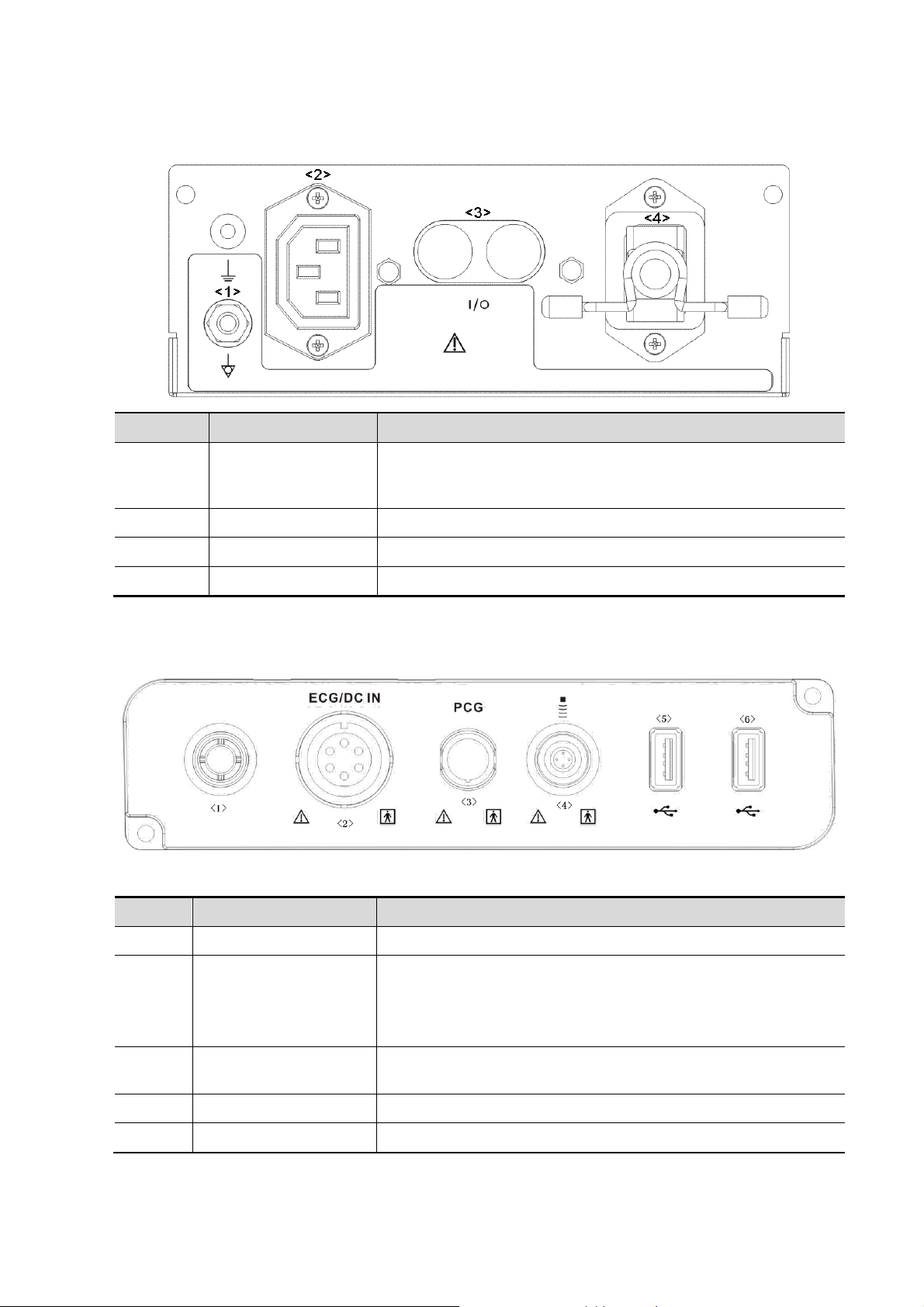
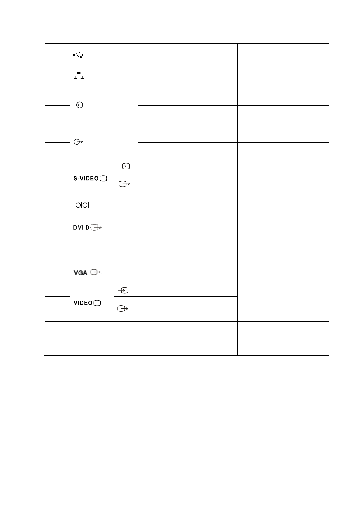
2.1.2.2 Power Supply panel
No.
Name
Function
1
Equipotential
terminal
Used for equipotential connection, that balances the protective
earth potentials between the system and other electrical
equipment.
2
Power outlet
Supply power for optional peripheral devices.
3
Circuit breaker
Used for switching off/ on the power supply.
4
Power inlet
AC power inlet.
No.
Name
Function
<1>
Reserved port
Port for reserved function.
<2>
ECG lead signal input
port / external ECG
signal input port
Connects to ECG leads, to directly obtain the ECG signals of
the patient.
Connects the signal output port of external ECG monitoring
device.
<3>
PCG signal input port
Connects to PCG transducer, to directly obtain the PCG
signals of the patient.
<4>
Pencil probe port
Used for connecting a pencil probe.
<5>/<6>
USB ports
Connects USB devices.
2.1.2.3 Physio Panel (ECG & PCG)
Specifications 2-5
Page 24
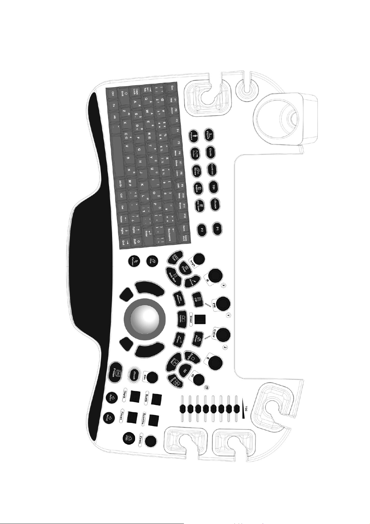
2.1.2.4 Control Panel
DC-8/DC-8 PRO/DC-8 CV/DC-8S
2-6 Specifications
Page 25
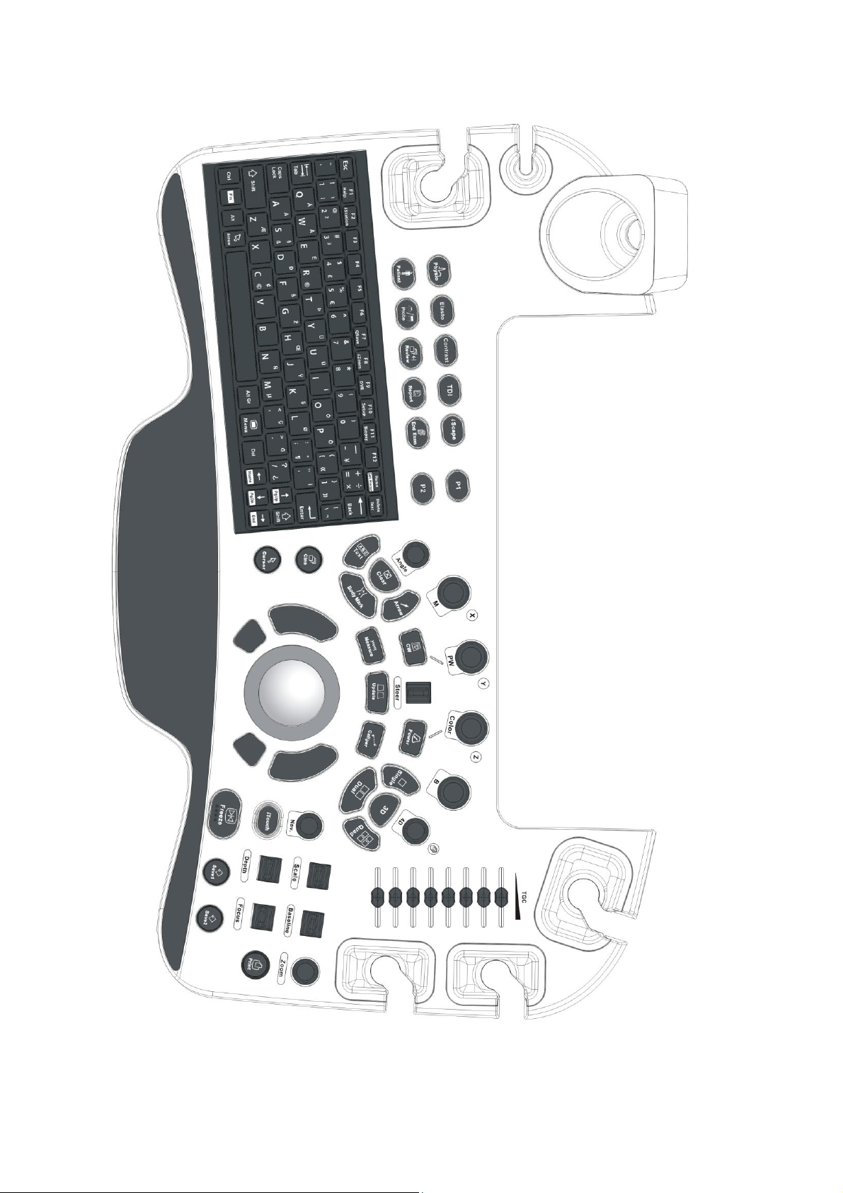
DC-8 EXP
Specifications 2-7
Page 26
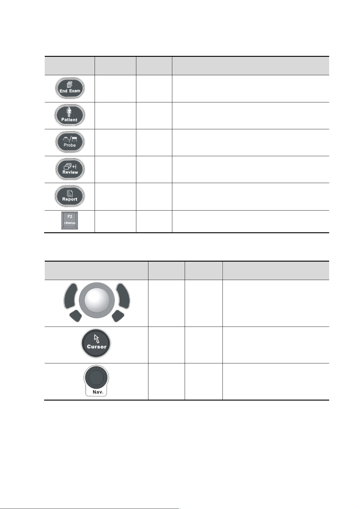
Exam Operation
Symbol
Name
Control
Type
Function
End Exam
Functional
button
End the current exam.
Patient
Information
Functional
button
Enter/ exit Patient Info screen.
Probe/Exam
switch
Functional
button
Switch probe and exam mode.
Review
Functional
button
Enter/ exit the Review screen.
Report
Functional
button
Open/ close the exam report.
/
Functional
button
Enter/ exit the Patient Info system.
Symbol
Name
Control
Type
Function
/
Trackball
Confirm
key
Move the trackball to change the
cursor position.
Select functions. The left/right
kidney shaped key is the <Set>
key.
Cursor
Functional
button
Show/ hide the cursor.
Navigation
Pressable
knobs
Multifunctional knob
Cursor Operation
2-8 Specifications
Page 27
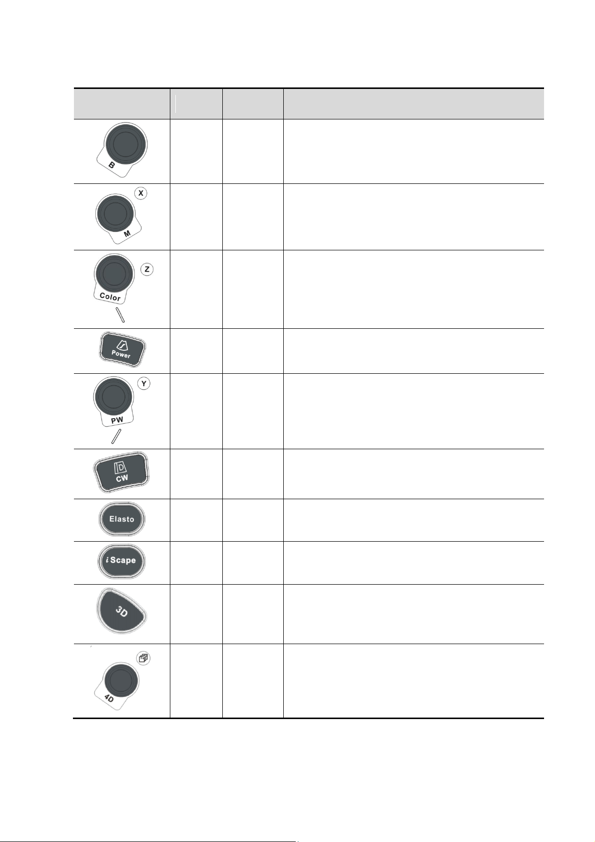
Image operations
Symbol
Name
Control
Type
Function
/
Pressable
knobs
Press to enter B mode; Rotate to adjust B mode gain.
/
Pressable
knobs
Press to enter M mode, and rotate to adjust M gain;
while in 3D/4D mode, rotate the knob to make the 3D
image to rotates around X axis.
/
Pressable
knobs
Press to enter Color mode, and rotate to adjust Color
or Power gain; while in 3D/4D mode, rotate the knob
to make the 3D image to rotate around Z axis.
/
Key
Enter Power mode.
/
Pressable
knobs
Press to enter PW mode, and rotate to adjust PW or
CW gain; while in 3D/4D mode, rotate the knob to
make the 3D image to rotate around Y axis.
/
Key
Enter CW mode.
/
Key
Enter elastography.
/
Key
Enter iScape.
/
Key
Enter 3D imaging function: Smart 3D or Static 3D.
/
Pressable
knobs
Press to enter 4D function; rotate to make the 3D
image rotation.
Specifications 2-9
Page 28
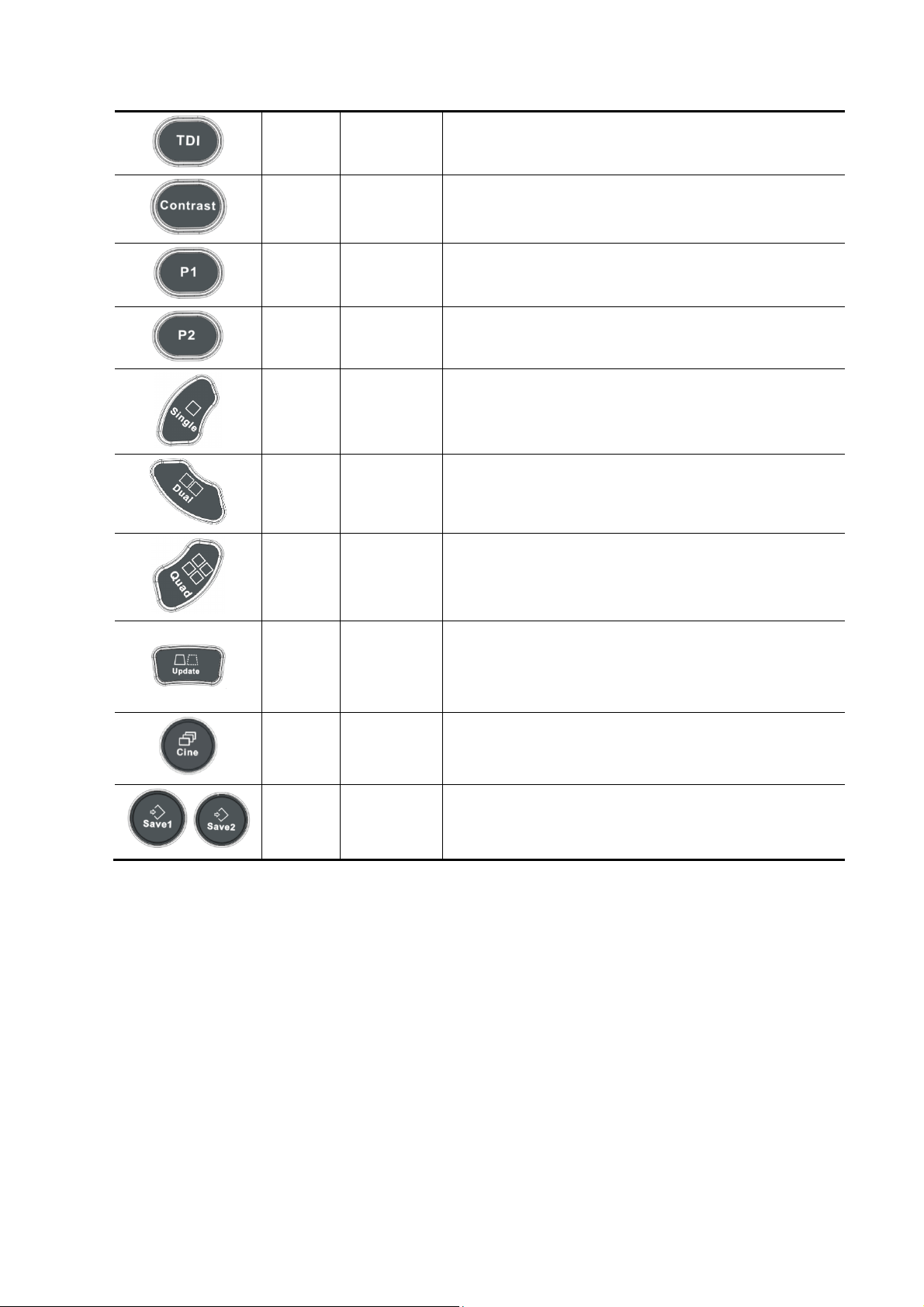
2-10 Specifications
/
Key
Enter TDI imaging.
/
Key
Enter contrast imaging.
/
Undefined
Button
Undefined Button, set by the user in preset.
/
Undefined
Button
Undefined Button, set by the user in preset.
/
Functional
button
Enter single window in multiple window mode.
/
Functional
button
Enter Dual mode in Non-Dual mode;
Switch between the two display windows in Dual
mode.
/
Functional
button
Enter Quad mode in Non-Quad mode;
Press to switch among the display windows in Quad
mode.
/
Functional
button
Switching key: Press to change the currently active
window.
Start/ stop image acquisition in iScape or 3D/4D
mode.
Cine
Review
Functional
button
Enter/ exit the Cine Review status.
/
Save 1/
Save 2
Functional
button
Save images in a way as preset.
Page 29
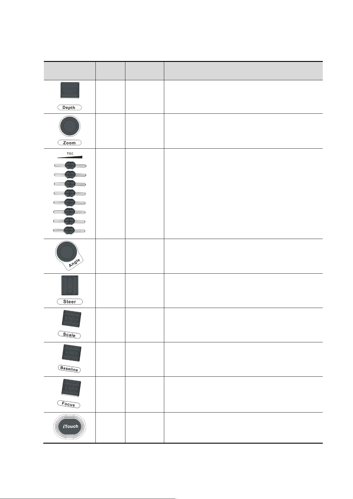
Parameter Adjustment
Symbol
Name
Control
Type
Function
Depth
Deflector
rod
Adjust depth in real-time imaging.
Zoom
Pressable
knobs
Rotate to enter the pan zoom mode, and press to enter
the spot zoom mode.
/
Slide bar
Adjust the depth gain.
Angle
Functional
button
Adjust angle.
/
Deflector
rod
Activate the steer function for linear probe.
/
Deflector
rod
Adjust scale parameter.
/
Deflector
rod
Adjust baseline parameter.
/
Deflector
rod
Change the focus position.
/
Functional
button
Optimize the image.
Specifications 2-11
Page 30
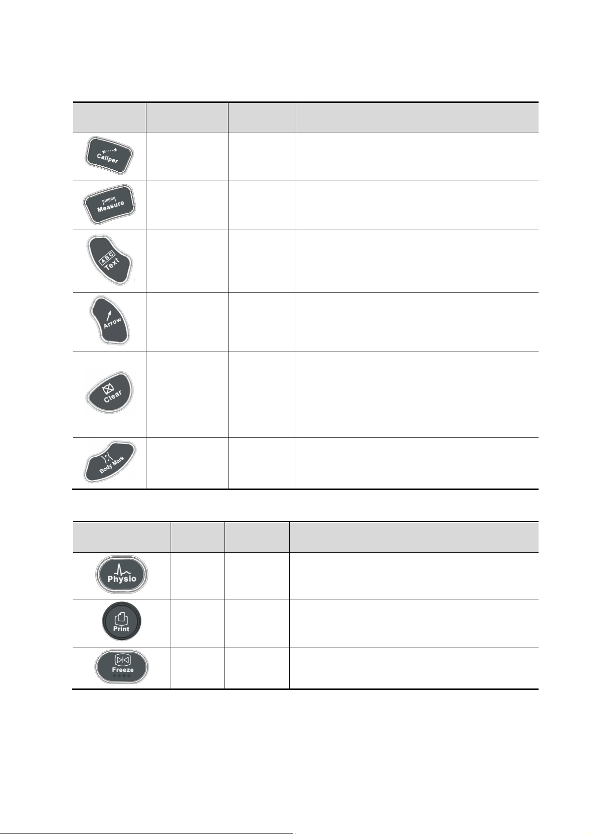
Measurement, Comment, and Body Mark Operations
Symbol
Name
Control
Type
Function
Measurement
Functional
button
Enter or exit the general measurement mode.
Caliper
Functional
button
Enter/ exit the application measurement mode.
Comment
Functional
button
Enter/ exit the textual comment status.
Arrow
Functional
button
Enter/ exit the arrow comment status.
Delete
Functional
button
Clear the measurement caliper, comments and
body mark.
Press <Clear> to clear the selected item, return to
the previous operation or to delete the last project.
Long press <Clear> to delete the mode related
elements or all elements on the screen.
Body Mark
Functional
button
Enter/ exit Body Mark.
Symbol
Name
Control
Type
Function
/
Functional
button
Enter/ exit ECG, PCG control screen.
Print
Functional
button
Print.
Freeze
Functional
button
Freeze/ unfreeze the image.
Other Operations
For user-defined keys, please refer to the user manual.
2-12 Specifications
Page 31

Voltage
220-240~,100-127V~
Frequency
50/60Hz
Power consumption
800VA
2.1.3 Peripherals Supported
Peripherals supported by this system please refer to the Operator’s Manual [Basic Volume]
attached.
2.2 Specifications
2.2.1 Dimensions & Weight
Dimension: 1355~1800mm (H)×930mm (D)×585mm (W)Net weight: about 110Kg
2.2.2 Electrical Specifications
2.2.2.1 AC Input
Specifications 2-13
Page 32

2.2.2.2 Battery
Voltage
11.1V
Capacity
4800mAh
Operating conditions
Storage and transportation
conditions
Ambient temperature
0℃~40℃
-20℃~55℃
Relative humidity
30%~85% (no condensation)
30%~95% (no condensation)
Atmospheric pressure
700hPa~1060hPa
700hPa~1060hPa
Warning :
Do not use this system in the conditions other than those
specified
Voltage
12V
Dimension
21.5 inch or 23.8 inch
Resolution
1920×1080
Visible angle
≥170
Voltage
12V
Dimension
10.4inch
Resolution
1024×768
Visible angle
≥170
2.2.3 Environmental Conditions
2.2.4 Monitor Specification
2.2.4.1 Main Monitor
2.2.4.2 Touch Screen
2-14 Specifications
Page 33

NOTE:
Do not install the machine in the following locations:
Locations near heat generators;
Locations of high humidity;
Locations with flammable gases.
WARNING:
DO NOT connect this system to outlets with the same circuit
breakers and fuses that control the current of devices such as
life-support systems. If this system malfunctions and
generates an over current, or when there is an instantaneous
current at power ON, the circuit breakers and fuses of the
building’s supply circuit may be tripped.
3 System Installation
3.1 Preparations for Installation
3.1.1 Electrical Requirements
3.1.1.1 Requirement of Regulated Power Supply
Power specification is showing in 2.2.2.Due to the difference of the power supply stability of
different districts, please advise the user to adopt a regulator of good quality and performance such
as an on-line UPS.
3.1.1.2 Grounding Requirements
The power cable of the system is a three-wire cable, the protective grounding terminal of which
is connected with the grounding phase of the power supply. Please ensure that the grounding
protection of the power supply works normally.
3.1.1.3 EMI Limitation
Ultrasound machines are susceptible to Electromagnetic Interference (EMI) by radio frequencies,
magnetic fields, and transient in the air wiring. They also generate a weak electromagnetic radiation.
Possible EMI sources should be identified before the unit is installed. Electrical and electronic
equipment may produce EMI unintentionally as the result of defect.
These sources include: medical lasers, scanners, monitors, cauterizing guns and so on. Besides,
other devices that may result in high frequency electromagnetic interference such as mobile phone,
radio transceiver and wireless remote control toys are not allowed to be presented or used in the
room. Turn off those devices to make sure the ultrasound system can work in a normal way.
System Installation 3-1
Page 34

3.1.2 Installation Conditions
3.1.2.1 Space Requirements
Place the system with necessary peripherals in a position that is convenient for operation:
1. Place the system in a room with good ventilation or an air conditioner.
2. The door is at least 0.8m wide. The ultrasound machines can move into the room easily.
3. Leave at least 20cm clearance around the system to ensure effective cooling.
4. A adjustable lighting system in the room (dim/bright) is recommended.
5. Except the receptacle dedicated for the ultrasound system, at least 3-4 spare receptacles on
the wall are available for the other medical devices and peripheral devices.
6. Power outlet and place for any external peripheral are within 2 m of each other with peripheral
within 1 m of the unit to connect cables.
3.1.2.2 Networking Pre-installation Requirements
Both wireless and wired LAN are supported by this ultrasound system.
Data transmission is allowed between different departments or areas without network cable.
Network can be automatically connected after disconnection in case that the device is required to
be moved, wireless transmission task can be recovered after the network resumed to normal
condition. Confirm the network devices and network conditions before the installation.
1. General information: default gateway IP address, and the other routers related information.
2. DICOM application information: DICOM server name, DICOM port, channels, and IP address.
3-2 System Installation
Page 35

3.1.3 Confirmation before Installation
Perform the following confirmation before installing the system:
1. The video format used in the region or country where the system is installed.
2. The language used in the region or country where the system is installed.
3. The power voltage used in the region or country where the system is installed.
4. Obstetric formulae and other measurement formulae used in the region or country where the
system is installed.
5. Other settings to be used in the region or country where the system is installed but different
from the factory settings.
6. The doctor’s habits of using the system.
Perform the confirmation above before installing the system. And set up the system to make it
according with the usage of the region or country where the system is installed.
3.2 Unpacking
Tool: scissors
Installation duration: 2 person, 0.5 hour.
3.2.1 Unpacking
1. Cut the eight bands rounding the box, see the figure below:
2. Remove the top wooden cover, take away the paper box upward, lay down the slopping
wood board, and stick the wood board with pallet together using velcro, see the figure
below:
System Installation 3-3
Page 36

3. Take away the probe carrying case, accessories case and the protecting foams, then cut
the bands rounding the machine, see the figure below:
4. Take out the frontal baffle-board.
5. Take the control panel handle to lift the machine slightly, remove the frontal baffle-board
(two person ), see the figure below:
3-4 System Installation
Page 37

6. Unlock the casters, hold the hand holder and lift up the machine (make the posterior casters
landing on the ground), and then push down the machine carefully.
3.2.2 Notice of Packing
Please operate as follows when packing the machine again: As shown in the figure, dial the
white fixing perch between two supporting arms, meanwhile, press the supporting arm down to the
lowest position (about 45 degree from horizontal position) then do the related operation.
System Installation 3-5
Page 38

3.2.3 Checking
NOTE:
When install the machine, the customer Service engineer should check rising and
lowering of machine. If the function is abnormal, follow the operations as shown in
7.5.
NOTE:
To prevent the machine from damage, when you perform the following operations,
please lock the casters if the machine doesn’t to be moved
NOTE:
Take care of your hands when adjust the monitor up and down.
1. After unpacking, check the objects in the container with the package list to see if anything is in
short supply or is wrong.
2. Inspect and make sure there is no damage to the machine, no indentation, no cracks.
3.3 Installation of Main Unit
3.3.1 Open up the Monitor
Adjust the monitor to the position as shown in the figure below.
3.3.2 Connecting the Power Cord
1. Push the retaining clamp upward, and insert the power plug into the receptacle, as shown in the
figure (a) below.
3-6 System Installation
Page 39

NOTE:
Make sure to allow sufficient slack in the cable so that the plug is not pulled out of the
wall if the system is moved slightly.
2. Push the retaining clamp downward, and lock the power cord, as shown in the figure (b) above.
3. Plug the other end power plug into an appropriate outlet. The grounding terminal should be
connected with a power grounding cable to ensure that protective grounding works normally.
3.3.3 Connecting ECG
Connect the ECG cable to the corresponding interface on the physio panel.
3.3.4 Install Endocavity probe bracket
Fix the endocavity probe bracket with two M4X12 screws as follow:
System Installation 3-7
Page 40

3.3.5 Connecting the Transducer
NOTE:
Before inserting the connector into the probe port, inspect the connector pins. If any pin
is bent, do not use the probe until it has been inspected / repaired / replaced.
Four sockets (A, B, C, D) are configured on the system; Every socket can be connected with all
types of supported transducers.
1. Keep the cable end of the transducer to the right side of the system, and insert the connector
into the socket of the system, and then press in fully. (Shown as the left figure)
2. Turn the lock handle 90° clockwise to lock it securely. (Shown as the right figure)
3. Place the probe properly to avoid being treaded or wrapping with other devices. DO NOT allow
the probe head to hang free.
4. Turn the lock handle 90°anticlockwise to unlock it, and then pull out the connector.
3.3.5.1 Using the Probe Dust-proof Cover
If a probe port is not used for a long period of time, please use the dustproof cover to protect the
probe port from dust; otherwise bad contact may result.
3.4 Installing Peripherals
For the models of the supported peripherals, please refer to “2.1.3 Supported Peripherals”.
3.4.1 Connecting the Footswitch
1. Directly insert the USB plug of the footswitch to the system applicable USB ports.
3-8 System Installation
Page 41

2. Function setting: for details, please refer to “3.5.3 System Preset”.
3.4.2 Installing a Graph / Laser Printer
The graph / laser printer is connected to the system via the USB port on system. As shown in the
figure below, a graph / laser printer has a power cord and a data cable.
1. Connect the data cable with the USB port on the system.
2. Connect the power cord to an appropriate power supply.
3. Printers listed in this manual (referring to 2.1.3) have drivers installed already.
3.4.3 Installing Video Printer
The system support both black/white video printers (analog and digital) and color video printers
(analog and digital).
CAUTION: The auxiliary power outlet in the system is used to supply power for
approved peripheral devices. Do not connect other/unapproved devices to this
outlet; otherwise the rated output power may be exceeded and the system
failure may result. Maximum output power of the outlet is 240VA.
3.4.3.1 Analog Video Printer
B/W Analog Video Printer
System Installation 3-9
Page 42

Take UP-897MD for example.
1. Plug the AC power cord hidden in the compartment under the control panel of the system to the
AC LINE port of the printer.
2. Connect the video signal cable in the compartment to the VIDEO IN port on the printer, and
connect the Remote control cable to the Remote port on the printer.
3. Place the printer inside the compartment. Place another printer, if available, on the platform
behind the control panel.
Note: Analog video printers do not need to install drivers. Other analog video printer’s installation
procedures are the same as those of UP-897MD.
Installing a B/W Video Printer
Color Analog Video Printer
Connect the power cable to an appropriate power supply. Other cables are as follows:
3-10 System Installation
Page 43

Installing a color video printer
3.4.3.2 Digital Video Printer
The installation method of B/W digital Video Printer is similar to color digital Video Printer. Take
MITSUBISHI P93DC for example.
1. Place the printer inside the compartment. Place another printer, if available, on the platform
behind the control panel.
2. Plug the AC power cord hidden in the compartment under the control panel of the system to the
AC LINE port of the printer.
3. Connect the USB video cable in the compartment to the port on the printer.
4. Printers listed in this manual (referring to 2.1.3) have drivers installed already.
3.4.3.3 Wireless Printer
HP e-All-IN-ONE B210a is a wireless printer used for report printing (not supported by Doppler
system V4.0 and later version).
1. Plug the printer power cord to an appropriate outlet.
2. Power on the system and the printer.
3. Make sure the ultrasound machine and the printer are connected to a same LAN, and turned
on the W-LAN function of the printer.
4. Open the [Preset]→[Printer Preset] page, select “Report Print” in the printer list, and then select
the printer to be HP e-All-IN-ONE B210a, and set properties.
5. Click [OK] to exit the preset and make the settings effective.
3.4.4 Installing Barcode Scanner
The system supports barcode reader to read the patient information (ID).
1. For structure of the scanner, see the figure below. The important parts are: LED indicator,
scanning surface, and the switch.
System Installation 3-11
Page 44

2. Connect the cable to the port on the scanner.
3. Connect the other end of the cable to the USB port on the ultrasound system.
4. When the ultrasound system is working, information scanning can be performed by pressing
the switch on the scanner. For detailed operations, please refer to the operator’s manual of the
scanner.
5. Fix the scanner on the bracket (see the figure below) to avoid accidental falling.
2D scanner 1D scanner
3-12 System Installation
Page 45

3.5 System Configuration
3.5.1 Running the System
Connect the AC power; make sure the ultrasound system and other optional devices are correctly
connected.
The circuit breaker should be in the [Up] position for the system to be operational. When the AC
power indicator on the control panel is light on (indicator is in green), press the power button
on the minor control panel to turn on the system.
3.5.2 Enter into DOPPLER
After system is turned on and wait for about 1 minute (for system initialization), it will enter into
Doppler interface, see the figure below:
3.5.3 System Preset
1. Press <F10> on the keyboard to open the Setup menu.
System Installation 3-13
Page 46

No.
Item
1.
Region: preset the hospital name, date and time, and select the language.
2.
Key Config: preset the function of user defined keys (F3~F6, F12, P1, P2) and the
footswitch, key lightness, key volume and trackball speed can be adjusted.
3.
General: preset the time in standby mode, set the brightness/contrast of the display.
2. Click [System Preset] to open the System Preset screen.
The following settings can be performed on the System Preset screen.
3.5.4 Print Preset
1. Press <F10> and click [Print Preset] to set video printer, graph/laser printer parameters (do the
setting according to the printer, and select the printer services correspondingly).
3-14 System Installation
Page 47

NOTE:
1.
Before adding the local printer, make sure the printer is powered on, and the
printer has been correctly connected with the ultrasound system(sound
feedback will be heard during the connection)
2. The printer related information will be displayed automatically, if additional printer is needed, click
[Add Printer] to do the setting. Click [Next] on the Add Printer Wizard screen to open the following
screen.
Add Local printer
a) Select “Local printer attached to this computer”, then click [Next], the system will detect the
printer connected with the ultrasound machine.
b) If no printer has been detected, then manual installation should be performed.
Note: in the printer driver installation procedure, use the right <Set> key to operate.
When you install the printer’s driver, you must specify the specific path for installation; otherwise,
vague path may result in longer time for searching.
System Installation 3-15
Page 48

2.
In case of installation failure in Doppler, try to install the printer in Windows
(click [Enter Windows] on the Maintenance menu). If the installation can’t be
performed neither in Doppler nor Windows, then the printer can’t be supported
by the ultrasound system.
3.
Use the original drive disk to perform the drive installation.
Add network printer
NOTE:
1.
Before connect the network printer, make sure the ultrasound system and the
printer are in the same network domain, and the network is working normally.
2.
When add a network shared printer, if the server has set accessing limitation,
the system will prompt a dialogue box to identify the user. Enter the correct
user name and password, click [Auto Connect], and then click [OK].
3.
Make sure to enter a valid printer name, e.g., \\server\printer, otherwise the
connection may be fail.
Select “A network printer, or a printer attached to another computer “; click [next] to add the
network printer.
3. After successful connection, the printer name will be listed out on the Printer list.
3.5.5 Network Preset
In Doppler version earlier than 04.00.00, open “[Setup]→[Network Preset]→[Local TCP/IP Setting]”
to enter the following screen.
In Doppler 04.00.00 and later version, click the network icon on the system tool bar at the right
lower coner, to enter the following screen.
3-16 System Installation
Page 49

NOTE:
IP address of the system should be at the same network segment as that of the
server.
NOTE:
Only if DICOM basic option is configured, [DICOM Preset] is available.
a) Click [IP Config] to enter the following dialog box:
b) Select “DHCP”, and then click [Apply].
c) Or, select "Static", input the IP address, subnet mask and gateway, then click [Apply].
3.5.6 DICOM Preset
1. Click [DICOM Preset] to open the DICOM Preset screen. Enter the AE Title of the ultrasound
system, port and PDU according to the actual situation.
2. DICOM Server Setting
1) Enter the device name and the IP address.
2) You can ping other machines to verify connection after entering the correct IP address by
System Installation 3-17
Page 50

clicking [Ping].
NOTE:
1.
AE Title should be the same with the SCU AE Title preset in the server
(PACS/RIS/HIS).
2.
DICOM communication port should be the same with the one in the server.
3.
If the currently entered name has already existed, the system will pop up:
“The server name exists!” Click [OK] to enter another name.
3) Click [Add] to add the server to the list if the connection works normally.
The following is an example:
3. Click [DICOM Service].
When the system is configured with DICOM basic function module, and installed DICOM
Worklist, MPPS, DICOM Structured Reporting and Query/ Retrieve modules, the corresponding
preset settings can be found in DICOM Service screen.
3-18 System Installation
Page 51

NOTE:
Only if DICOM basic option is configured, Worklist page is available.
NOTE:
1.
Be sure to confirm the system information before and after the software
maintenance.
2.
If necessary, please ask the user to save the current system information.
The DICOM Service Setting is used to set properties of DICOM services as Storage, Print,
Worklist, MPPS, Storage Commitment and Query/ Retrieve. The detailed information please refer to
“DICOM” of user manual.
3.5.7 Check System Information
In System Information screen, it displays the product configuration, the optional installation status,
software version, hardware & boards, and driver related information. You can check the product
information here.
1. Press <Setup>, and then click [System Info] to open the following screen.
2. On About Detail page, system hardware & board related information can be seen.
3. Confirm the system information is correct, and then export the system information in a file
of .txt format.
System Installation 3-19
Page 52

Page 53

Communication
&control
Power supply
Ultrasonic signal
Clock signal
Back -end mother board
ECG/PCG
board and
USB
extending
board
Control
panel
Display&
touch
screen
DVD-R/W
Back- end
power board
Battery
AC Input
Charge/
discharge
DC power
Signal port
Power supply unit
USB
Fan
Auxiliary output control
Isolation
transformer
Power
supply
connecting
board
AC-DC
power
board
Probe
board
Front-
end
analog
mother
board
CW board
Transmission
board A
Transmission
board B
Receiving
board
Signal
processing
board
Commu
nication
mother
board
Front- end power
board
(main/auxiliary)
Digital
board
4D or
4D&TEE
board
Front- end unit
Back-end unit
cable
conne
ction
Ultrasound
Gel Heater
IO BOX
board
Back-
end
board
4 Product Principle
4.1 General Structure of Hardware System
Symbols illustration
Figure 4-1 Schematic Diagram of System Hardware
As described in the figure above, the hardware consists of the following units:
Front-end unit (probe board, CW board, transmission board A, transmission board B,
receiving board, Signal processing (DSP) board, front-end analog motherboard,
communication motherboard)
Back end unit (digital board, 4D or 4D&TEE board, IOBOX board, back end motherboard);
Control panel unit;
Main display unit;
Touch screen unit;
ECG/PCG board;
Product Principle 4-1
Page 54

Power supply unit (front-end power board, back -end power board, AC/DC power board).
Front-end analog motherboard
Transmission
board B
High
voltage
isolation
TGC
CW board
Beamformer
FPGA 1
DSP
FPGA
PCIE
Receiving board
ADC VGA LNA
Clock
circuit
Probe board
64-channel transmissionCommunication control bus
Communication
control bus
Communication
motherboard
128-channel analog
Analog transmission&receiving
Digital echo
Clock 3
Clock 1
Clock 4
Clock 6
Control signal
Transmission
board A
64-channel transmission
Communication control bus
Clock 2
Beamformer
FPGA 2
Beamformer data
Signal processing board
Communication
control bus
Clock 5
High
voltage
isolation
ADC VGA LNA
Clock 7
4.2 Ultrasound Front-end Unit
Fig 4-2 Schematic diagram of ultrasound front-end unit
Front-end unit mainly consists of:
Probe board
CW board;
Transmission board A and transmission board B;
Receiving board
DSP board (Signal processing board for short ,supporting 4D and elastography);
To separate the analog area from the digital area properly, front-end analog motherboard (mainly
contains front-end analog signal channel) and communication motherboard (mainly contains digital
signal and power channel) are added to the system. Front-end receiving unit carries out
128-channel transmitting and receiving. The ultrasound image signal will be sent to the CPU
module on the digital board for post processing after amplification, A/D conversion, beam forming
and signal processing.
For details of the boards, see the following chapters:
4-2 Product Principle
Page 55

4.2.1 Probe Board
Front-
end
analog
mother
board
Probe socket D
Probe socket C
Probe socket B
Probe socket A
Signal switch
( relay unit )
…
CPLD
Probe related control
signal
Pencil probe socket
245 drive
4D&
TEE
signal
socket
CW transmitting & receiving signal
CW_POUT
4D&TEE signal
Transmitting & receiving signal
Probe control
circuit
…
Probe control signal
A+12V/A+5V7/A+100
V/A-100V
Pencil probe/probe present signal
Signal switch
( relay unit )
Transmitting& receiving
signal POUT
Pencil
probe
signal
socket
Pencil probe
socket
Probe board
Fig 4-3 Schematic diagram of probe board
Hardware structure of the probe board is shown as the figure above:
Functions of the probe board are:
Supports 256/192/128elements probes, 4D probes, 128/96/64-elements phased array probes
and TEE probes;
Probe board only supports 128 channels; for 192/256elements probe, elements switching is
performed in the probe to match 128 channels on board. Including four 260-pin probe sockets.
Supports 4 probe ports switching and ID recognition of probes on every port. The circuits for
ID recognition and probe switching are independent.
Supports echo signal channel switching, outputting CW signal independently which can
improve CW signal-noise ratio.
Product Principle 4-3
Page 56

4.2.2 CW Board
Front-end
analog
motherboard
Probe board
Low
pass
filter
ADC
Q channel
I channel
Low-
pass
filter
ADC
LNA
Demodulati
on circuit
LNA
Signal processing board
Pencil probe
CW pulse
transmitting
circuit
Board-to-board connect socket
Board-to-board
connect socket
Board-to-board
connect socket
Digital echo
Control signal
A+12V/A-12V/A+19V/A+5V7/A5V7/A+4V/A+3V3/A+2V5/A+1V8
Clock
CW board
Demodulati
on circuit
Adder
(multiplex
composition )
Adder
(multiplex
composition )
AD collection after
demodulation
AD collection after
demodulation
Front end
power board
Receiving
board
FPGA
Communication motherboard
Board-to-board connecting socket
Communi
cation
mother-
board
High-
voltage
pulse
output
circuit
Drive
circuit
Transmitting
control
FPGA
Transmission board
64-channel
transmitting
Communication
control bus
Scanner time
sequence
Clock
4-channel
PHV
A+12V/A-12V
/A+4V2/A+3V3
/A+1V8
Board-to-board
connect socket
Front
-end
analog
mother
board
Board-to-board
connect socket
Fig 4-4 Schematic Diagram of CW Board
Function (Only phased array probe and pencil probe are supported):
Realizing transmitting, receiving and beam forming of CW signal;
Parameter control and mode switching in CW mode;
Data output by beam former are output to DSP board, and then
upload to CPU module for CW image processing via the upload logic chip.
The system can communicate with the CW board via the communication control bus.
4.2.3 Transmission Board
Fig 4-5 Schematic Diagram of Transmission Board
Hardware structure of the transmission board is shown as the figure above. Realize 128-channel
transmission pulse. For 192/256-elemented probe, the high voltage switching is realized in the
housing of the probe. There are two transmission boards: board A and board B, each board takes
charge of 64-channel transmission pulse. Board A and board B are the same, so both of them are
named transmission board. Only difference is the position.
Function:
4-4 Product Principle
Generate 64-channel transmission waveform according to the scanning sequence and
control parameter.
The 64-channel transmission waveforms are drove into 64-channel high-voltage
transmission pulses by the drive circuit.
Page 57

Front-end analog motherboard
ATGC
High-voltage
isolation
AFE chip
Board-to-board connect socket
Board-to-board
connect socket
cable connection
Digital echo
Control signal
A+12V/A+19V/A+5V7/A5V7/A+4V2/A+3V3/A+2V5/A+1V8
Clock
Receiving board
AFE chip
Beamformer
FPGA 1
Communication motherboard
High-voltage
isolation
Beamformer
FPGA 2
Clock
circuit
DDR2
The system can communicate with the transmission board via the communication control
bus.
4.2.4 Receiving Board
The main structure of the receiving board is shown as the figure below, which consists of
high-voltage isolation, ultrasonic receiving, beam former, etc.
Function:
High-voltage isolation;
LNA, VCA/PGA, LPF, ADC, which are performed by the integrated front-end chip;
ATGC module, voltage gain control module;
Beam former, performed by FPGA;
Clock module, the clock source of the whole front-end unit is on the receiving board, clock
buffer is sent to the corresponding board via communication mother board.
Power module, receiving the power from the communication mother board and transferring it
into power required by receiving board
Configuration module, configure the FPGA on the board.
Fig 4-6 Schematic Diagram of Receiving Board
4.2.5 Signal Processing Board
The signal processing board can be divided into two kinds: one kind can support 4D and
elastography, while the other one doesn’t support 4D and elastography. When 4D/TEE board is
selected, the corresponding signal process board should be used.
The hardware structures of the two boards are shown as follows:
Product Principle 4-5
Page 58

Communication motherboard
Signal
processing
FPGA
PCIe
Communic
ation bus
EDC+12V
Memory
Power
DSP
FPGA
SRIO
clock
Memory
Memory
Clock
Clock
Board-t-board connect socket
Data bus
Signal processing board
Communication motherboard
Signal
processing
FPGA
PCIe
Communi
cation bus
EDC+12V
Memory
Power
Clock
Board-to-board connect socket
Data bus
Signal processing board
Fig 4-7 Schematic Diagram of Signal process board (support 4D and elastography)
Fig 4-8 Schematic Diagram of Signal process board (not support 4D and elastography)
Function description:
Digital signal process in B, C, D imaging modes.
The imaging data will be packed and then uploaded to digital board CPU module for post
processing.
DSP chip is designed for elastography data processing, optional function.
A FPGA is designed for New Color etc. Signal processing, reserved function.
4-6 Product Principle
Page 59

PEN_RX/TX
CW_POUT[128:1]
Probe board
communication
and control
signal
Probe board
power supply
Probe board
Front-end
analog
motherboard
CW
board
Transmission
board A
Probe board power supply
TX1
TX64
4D drive and others
BTB
PEN_ID
Probe board communication
and control signal
BTB
BTB
POUT [96:33]
POUT [32:1]
POUT [128:97]
POUT[128:1]
PEN_ID
PEN_RX/TX
4D drive and
others
WTB
CW_POUT[128:1]
POUT[128:1]
Transmission
board B
TX1
TX64
Receiving
board
To 4D or
4D&TEE
board
4.2.6 Front-end Analog Mother Board
Fig 4-9 Schematic Diagram of Front-end Analog Mother Board
Function description:
Signal transmission between probe board and other front-end boards.
Analog signal transmission of front-end boards.
Product Principle 4-7
Page 60

4.2.7 Communication Mother Board
CW
board
Receiving
board
Transmission
board A
Communication
motherboard
Transmission board
power supply
Clock
Clock
Clock
Receiving board
power supply
CW board
power supply
RF data and control
communication
Rf data and front-
end bus
Transmission A
control
communication
CW control
communication
CW upload
BTB
BTB
CW
communication
Transmission
board B
Transmission board
power supply
Clock
Transmission B
control
communication
Transmission A control
communication
Transmission B control
communication
BTB
BTB
BTB
BTB
Digital
board
Signal processing
board power supply
HV_EN
Acoustic power test signal
Rate signal
RATE_DSP
RATE_TXA
RATE_TXB
Front-end
power board
(main/auxiliary)
Signal
processing
board
4D&TEE
board
Front-end
power supply
Control and detect
the signal
PCIE *4
IOBOX
board
Ultrasound machine
internal port
Ultrasound machine
internal port
4D SPI control
signal
ECG serial port
ECG serial port
JTAG signal
JTAG signal
Fig 4-10 Schematic Diagram of Communication Mother Board
Main functions of the communication motherboard are:
Digital signal transmission of the front-end boards;
Control parameters transmission of the front-end boards;
Power supply signal transmission of the front-end boards.
4-8 Product Principle
Page 61

Multi-
function
FPGA
Digital board
COM-E
CPU module
PCIE
To signal
processing board
Back-end
motherboard
IO BOX board
HDMI
DVI ……..
Video-out Video-in SVideo-in
SVideo-outUSBUSB
Communication
motherboard
4D or 4D&TEE
board
Video
transfer
Multifunction
FPGA
COM-E
CPU
module
DVI
VGA
HDMI
S-Video
CVBS
Serial port
remote_Print_C
VGA
1Gbit Ethernet
USB port
Audio out
Audio
output
Dual speaker
PCIE
Control bus LPC
CVBS Video in
S-Video in
Audio in
MIC in
DVI
IO
BOX
CVBS
Main
display
LCD
PCIE X1 for WLAN
B/W
video
print
Touch
screen
USB
UART X2
Back-end
power
board
SMBUS for WLAN
To
Front-end
unit
boards
Data bus LVDS
Digital board
remote_Print
Temperature monitor and
clock enable signal
ECG control signal etc.
Sound
card
4.3 Ultrasound Back-end Unit
The back-end unit mainly consists of: digital board, back-end motherboard, IOBOX board, 4D, etc.
See the figure below:
Fig 4-11 Schematic Diagram of Back-end Unit
4.3.1 Digital Board
The block diagram of the digital board is shown as below:
Fig 4-12 Schematic diagram of the digital board
Product Principle 4-9
Page 62

Main functions of the digital board are:
Standard COM-E socket;
Back-end video processing, realize CPU module video output extending.
a) DVI, 2 channels, used for main monitor and IOBOX board external display port, the
resolution should support 1680×1050@60Hz
b) VGA, 2 channels, one channel is used for external VGA port display extending,
resolution 1680×1050@60Hz. The other channel is used for touch screen display, the
resolution should support 1024×768@60Hz.
c) Composite Video, 1 input, 2 outputs, used for external video output and internal B/W
video printer, support PAL/NTSC switching.
d) S-Video, 1 input, 1 outputs, support PAL/NTSC switching.
e) HDMI port, 1 channel, not support audio, the resolution are the same as that of the
main monitor.
Audio processing
a) Audio 1 input, 1 output, left and right stereo
b) Power amplify output, the maximum single channel power is 12W, left and right stereo
c) Support external MIC input.
Port support
a) G-bit Ethernet port, 1
b) WiFi port
c) Support footswitch, USB port
d) Video print control port, 2, for both B/W and color
e) SATA port, 2, DVD and HDD
f) USB port, 10 channels, of which, 6 for external (2 at the front side, 2 at the lateral side and
2 at the backside), 4 for internal (connect the touch screen, keyboard, audio/video
collection, digital video compress)
Communication bus
a) PCIE×4, 1channel, front-end data and control communication port.
b) PCIE×1, 1 channel, WiFi module support
c) UART, 4 channel, 2 power modules, 1 external serial port, 1 DVR control port (reserved),
the external serial port is transferred by USB, other serial ports will be transferred by LPC
bus through multifunction.
d) SMBUS, 1 channel, reserved for WiFi module
e) LPC, used for multifunctional communication control and transfer extending for part of the
serial ports.
Besides, there is a multifunctional FPGA on the digital board for multifunction controlling, the
FPGA takes charge of video format conversion, back-end control, port extending, etc. It mainly
includes:
Display extending:
4-10 Product Principle
Page 63

Digital
board
SODIM
M-144
Socket
Golden
finger
DM368
USB port
Audio in
5V/3V3/1V8
DDR2
memorizer
Power
supply
Control signal
Video in
DVR board
SD Card
Convert LVDS signal to all other video formats required by video output port chips, time sequence
conversion, vide cutting and filling.
Digital video port.
Supports digital video compress and storage, and the related control.
Back-end communication and control
Extend serial port, used for battery management, high-voltage controlled SCM communication, etc.
The functions are realized by the multifunctional FPGA using LPC bus.
Video print control, support video printer connecting.
Support I2C port, used for monitor status obtaining, parameter writing, etc.
4.3.2 DVR Board
Fig 4-13 Schematic Diagram of DVR Board
Function description:
Support video compress and storage.
Only supports digital video, the resolution is 1680×1050@60Hz.
The analog video compressing and storage function is reserved.
Support audio compress and storage
Video files can be output to the USB port and DVD-R/W.
Product Principle 4-11
Page 64

4.3.3 IO BOX Board
Communication motherboard
Digital
board
VGA
HDMI
S-Video
CVBS
Serial port
Remote_Print_C
Ethernet
USB port
Audio out
CVBS Video In
S-Video In
Audio In
DVI
WLAN
IOBOX
board
JTAG and acoustic
power port
DVR
board
WIFI
module
HDD
Function description:
IOBOX board is used for output and input for the peripherals, the main ports including:
DVI port
VGA port
HDMI port
Video input
Video output
S-Video input
S-Video output
Audio input
Audio output
USB port, 2
Ethernet port
Note: if not specified, the number of the above ports is 1.
For the convenience of system test and debugging, the following ports are designed on the IOBOX
board:
JTAG port of the FPGA
JTAG port of the DSP
Acoustic power test port
4-12 Product Principle
Fig 4-14 Schematic Diagram of I/O Box Board
Page 65

Low-pass
filter
ADC
Signal
amplification
DAC
Temp/angle
signal
detection and
amplification
Communication motherboard
Board-to-board connect
socket
Commu
nication
control
signal
Power
amplification
Voltage
control
Motor
drive
signal
Hall feedback signal for 4D probe
TEE
probe
support
signal
D+12V/D-12V/D+3V3
Back-end motherboard
cable connection
Board-to-board connect
socket
Front-end analog motherboard
Probe board
4D
probe
TEE
probe
Board-to-board connect
socket
J32
J7
J9
J10
J3Battery
B/W
printer
DVD-
R/W
SATA
Drive power
Air outlet
fan
J13
Power
Control
panel
J12
USB and status
J18
Front Cover
USB
connecting
board
USB
ECG
Power supply,
serial port
J11
Main
monitor
Power
J26
DVI
J16 J17 MIC
Speaker
J53 J52 J51
AC/DC
Power
board
Touch
screen
J14
J27
J15
RGB
Power
I2C
J21 J22
J23
Digital
board
J4 J3
Back-end
power board
Front-end
power board
J1
J6
4D or
4D&TEE
board
Analog
mother
board
J24
AC
input
J25
J30
Power
connecting
board
Air inlet
fan
Back-end
motherboard
4.3.4 4D or 4D&TEE board
Fig 4-15 Principle Block Diagram of 4D or 4D&TEE board
Function description:
Power amplification for 4D drive signal; output required signal to drive the probe to the
designated position
Provide 4D Hall signal returning channel.
Amplify and collect the TEE probe temperature and angle signal.
4.3.5 Back-end Motherboard Connection
Product Principle 4-13
Page 66

CPU module
ADT7462(A)
SMBUS1
ADT7462(B)
Multifunction FPGA
LPC
ADT7462(C)
SMBUS2
Temperatures in
the front end power
Voltages in the
front end power
Back end
power
Temperatures in
the main unit box
Fans in the main
unit box
Digital board
Front end power board
Fig 4-16 Back-end Motherboard Connection
The figure above shows the cable and socket connection on the back-end motherboard, and the
connection with the other boards and modules.
4.3.6 Ultrasound System Monitoring
Fig 4-17 Block Diagram of Ultrasound system monitoring
Function description:
Use ADT7462 chip to monitor system voltage, temperature and fans, Circuit structure is
shown in the figure above.
The communication between CPU and ADT7462 is realized by the SMBUS supported by
FPGA.
Two pieces of ADT7462 on the digital board are used for main unit box fan, back-end
power monitor and main unit box temperature monitoring.
1 piece of ADT7462 on the front-end power board is used for front-end power monitor and
temperature monitoring.
4-14 Product Principle
Page 67

Control panel
Back-end power board
Power-on status
indicator
Power
managem
ent
Drive
Battery
manage
ment
Drive
Back-end
motherboard
Digital board
CPU
module
Drive
5VSTB
5VSTB
3.3V
Standby status
indicator
Battery status indicator
HDD indicator
AC power status
indicator
Front-end
motherboard
IO BOX board
Power status indicators
12V
5V
3.3V
4.3.7 Indicators on the Ultrasound System
Fig 4-18 Block Diagram of Indicators on the Ultrasound System
4.4 Control Panel Unit
The control panel unit mainly consists of keyboard module.
The keyboard module consists of on/off key, retractable keyboard, trackball, TGC slider, and
encoder, including key volume and key light. The key, trackball, TGC and encoder are used for
signal input, key volume and key light for output.
USB HUB is adopted for USB extending on the keyboard. See the figure below, the following
function circuits are designed on the control panel.
On/off key circuit;
TGC adjust circuit;
Trackball circuit;
LED drive control circuit;
Key volume circuit;
FPGA control circuit;
Encoder circuit;
USB HUB circuit.
Product Principle 4-15
Page 68

5 status
indicators
TGC board
Digital key
board
Function
key
Encoder
board
Key
scan
LED constantcurrent source
drive ciruit
Key backlight
LED
USB
port
chip
ADC
circuit
Buzzer
Buzzer drive
circuit
Main controller
TGC
scan
PWM generating
circuit
FPGA
Keyboard
Back-end motherboard
USB1
+12V,+5V
USB
HUB
interface
Trackball
key board
USB
connecting
board
trackball
Touch
screen key
board
USB2
Comm
unicati
on
mother
board
Back-
end
mother
board
ECG leads
DC IN
PCG
transducer
Amplify
Filter
Sampling
R-
wave
detecti
on
CPU
module
ECG&PCG board
Digital board
Back-end
power board
+12V
USB extending
board
DSP
board
Serial
port
PCIE
Amplify
Filter
Sampling
Fig 4-19 Schematic diagram of control panel
4.5 ECG&PCG Unit
ECG&PCG unit, which mainly consists of ECG&PCG board, takes charge of ECG signal detection,
PCG signal monitor. After amplification, filtering, sampling and R-wave detection, the ECG/PCG
signal will be sent to DSP board. The detected ECG triggering signal will be sent to the uploading
logic on the DSP board through serial port, and then the signals will be sent to CPU module with
other image data.
The system can be connected with ECG leads and PCG transducer; the ECG leads are compatible
with the port on the patient monitor device of Mindray. Besides, USB extend board is adopted in the
ECG&PCG unit. USB signal from the digital board will be sent to USB extending board through
cables. For the user’s convenient, two USB ports are designed on the USB extending board.
Structure of ECG&PCG unit is described as below:
Fig 4-20 Schematic diagram of ECG&PCG unit
4.6 Main Monitor Unit
4-16 Product Principle
Page 69

Control board
Key
board
Parameter
board
LCD Screen
Back-end motherboard
+12V
+12V
Control
signal
Key
signal
+5V DVI I2C
LVDS 3.3V 3.3V
Parameter
communication &
brightness
feedback
Display
Status
indicator
Fig 4-21 Schematic diagram of the display
The display unit mainly consists of control board, LCD screen, parameter board, key board, etc.
Function:
The control board, as the main part of the monitor, transfers DVI input into LVDS signal then
output to the LCD screen, monitors other board or signal; meanwhile, it can communicate with
the main system through I2C port. So it is convenient for the main system gathering/controlling
information from the monitor.
Parameter board saves data of color temperature and gamma correction, and it is used with
LCD screen, so that the corresponding display effect shall be consistent. Meanwhile, it
monitors the backlight brightness of LCD. The control board will adjust the LCD backlight
brightness according to the current, transferring efficient of backlight or temperature changed,
the brightness of LCD screen can keep stable.
User can adjust part of the monitor parameters through key and menu.
Product Principle 4-17
Page 70

4.7 Touch Screen Unit
Main control board
Touch
screen
control
board
Parameter boardDisplay
Back-end motherboard
+12V
+5V VGA I2C
LVDS
+12V
3.3V
Parameter
communication
brightness feedback
Touch
screen unit
USB +5V
Control panel
Touch
screen
Backlight
control
Fig 4-22 Schematic diagram of touch screen
Touch screen unit mainly consists of main control board, parameter board, LCD, touch screen,
touch screen control board, etc.
Function:
Touch screen: 10.4 inches, 5-line resistor
The touch screen control board controls the touch screen, responds to the touch screen
operation, and communicates with the main system through USB port.
The main control board transfers the VGA input into LVDS signal output to the LCD screen, and
monitors other boards or signal.
The parameter board communicates with the main control board, controls the parameters and
brightness feedback.
4.8 Power Supply Unit
Power supply unit provides power to the system (front-end, back-end, peripherals, etc.). The power
supply unit consists of power connecting board/isolation transformer, AC-DC power board,
front-end power board, back-end power board, and battery module, etc. Of which, the front-end
power board consists of front-end power main board and front-end auxiliary board.
4-18 Product Principle
Page 71

Connecting
board
Isolation
transformer
AC-DC
power board
Back-end
power
board
Front-end
power board
Battery
EDC_+12V
D+12VSTB
Front end power
output
AC auxiliary output
AC input
EDC_+12V_EN_N
EDC_+12V_OK_N
Back-end control signal
Front end control
signal
Communication
motherboard
Back-end
motherboard
Back-end power output
Battery
Battery status signal
SMBUS
EDC_+12V
Surge
inhibit
circuit
Connecting board
EMI
inhibit
circuit
Relay
AC auxiliary
output
Mains power input
Auxiliary
output control
Isolation
transformer
Back-end
motherboard
Fig 4-23 Schematic Diagram of Power System
The mains power goes to the connecting board through the circuit breaker, it will provide power to
AC-DC power board after transferring, besides, it provides AC auxiliary output for peripherals
(printer, e.g.) after isolation transforming. Once the AC-DC power board is powered by the mains
power, it will provides D+12VSTB, which will power the Standby circuit on the back-end power
board. When received the system startup command EDC_+12V_EN_N, EDC_+12V will be output
to power the front-end power board, back-end power board and other +12V required. Other DC
power in the front-end and back-end will be generated from DC-DC conversion through front-end
power board and back-end power board.
Back-end control signal mainly consists of: system start-up/shut down logic, system status
indicating, temperature gathering, battery management, etc. Front-end control signal mainly
consists of power monitoring, temperature gathering and voltage programmable control, etc.
For details about the boards of power supply unit, please refer to the following chapters.
4.8.1 Connecting Board
Fig 4-24 Schematic diagram of connecting board
As the connection and current distributing part for mains power input, this part consists of
connecting board and isolation transformer.
Function:
Isolation transformer: realize AC auxiliary output power and mains power electrical
isolation.
Connecting board: provide connections ports for mains power input, isolation transformer,
mains power output, AC auxiliary output or signal connection ports, meanwhile, it controls
the On/Off of AC auxiliary output.
Product Principle 4-19
Page 72

4.8.2 AC-DC Power Board
APFC
circuit
EMI
filter
Shift full bridge
circuit
AC-DC power board
Back-end
mother
board
Mains power input
EDC_+12V
D+12VSTB
EDC_+12V_EN_N
EDC_+12V_OK_N
TM_ACDC_D*
Control circuit
Inverse circuit
Fig 4-25 Schematic Diagram of AC-DC Power Board
Function description:
The mains power is input to AC-DC power board after pass through the back-end
motherboard, pass through the EMI filter circuit, been rectified and filtered, then activate
the inverse circuit working, then output D+12VSTB to the back-end motherboard to
provide power to the back-end power board, and then the APFC circuit will work normally.
When system is turned on, it outputs EDC_+12V to power the front-end power board and
back-end power board.
The main power of AC-DC power board is EDC_+12V; maximum rated current is 55A,
realized by shift full bridge circuit and synchronous rectification. EDC_+12V output is
controlled, when the system is turned on, the enable signal EDC_+12V_EN_N is low,
power output is normal, otherwise there is no EDC_+12V output.
Output the board temperature and status signal of main power.
4-20 Product Principle
Page 73

4.8.3 Back-end Power Board
STANDBY
DC-DC
D+5V&D+
3.3V
DC-DC
D-12V
DC-DC
D-5V
DC-DC
FPGA
Power status
Power control
MCU
BATTERY
CHARGE
Charge enable
3V3STB_FPGA
3V3STB_MCU
D+12VSTB
EDC_+12V
Auxiliary output control
Temperature collection
BATT+
Battery temperature
Battery status and
communication
System On/off
status indicating
signal
D+5V
D+3.3V
D-12V
D-5V
D+5VSTB
Back-end power board
Power
management
Battery management
Power module
Back-end motherboard
D+12VSTB
Battery
assembly
Select
circuit
Fig 4-26 Schematic Diagram of the Back-end Power Board
Function description:
Back-end power board mainly consists of power management, battery management and
DC-DC power module. When the D+12VSTB of pre-level AC-DC power starts working, the
corresponding power management and batter management part begin to work, the system
enters into Standby mode, and the battery charge (supplied by D+12VSTB) circuit begins
to work.
The back-end power board, according to the CPU module status information and the
FPGA and battery current information. After the system is turned on, the powers except
Standby will output normally, to power the back-end boards. When system is in boot-trap
status, the power charge circuit still works normally.
When the machine is configured with battery, the machine can enter into standby mode
when it is powered on by mains power. And when the mains power is cut off, the battery
will power the system to make the system maintain in standby mode, until the battery is of
low capacity or the mains power is connected again. The battery only supports Standby
mode. And in this mode, the mains power is prior to the battery.
4.8.4 Front-end Power Board
The front-end power board consists of front-end power main board and front-end power auxiliary board.
See the figure below, the external ports of the front-end power board are realized by the front-end power
main board, the front-end power auxiliary board is connected with the front-end power main board, but
not connected with the other boards. The EDC_+12V is connected to the front-end power main board
through the back-end motherboard, meanwhile it is connected to the front-end power auxiliary
board to power the two boards. They are introduced respectively as follows:
Product Principle 4-21
Page 74

Front-end power
main board
FLYBACK
converter *4
PHV *4
A±95V
+19VCC
BOOST converter
Control & protect
EDC_+12V
A+5V7
A+4V2
A+3V3
A+1V8
A-5V7
A-12V
FLYBACK
converter
PHV feedback
Current-limit
circuit
A+2V5
Front-end power
auxiliary board
I/O
Back-
end
mother
board
Communic
ation
mother
board
BUCK converter
*5
BUCK-BOOST *2
Fig 4-27 Schematic Diagram of the Front-end Power Board
4.8.4.1 Front-end Power Main Board
Function description:
The front-end power main board mainly generates the ultrasound transmission power,
including 4 channels adjustable voltages PHV, 2 channel fixed voltages A±95V, 1 channel
+19VCC output ,and transfers all the powers generated by the power auxiliary board.
PHV control and feedback circuit mainly include three parts: ARM, ADC sampling and
operation & amplification. Main system CPU module can directly determine PHV voltage
and read the output voltages of each power (including the outputs from front-end power
auxiliary board).
Power sequence:
After each circuit module on the board is started, PHV and ±HV are still kept closed, PHV
and ±HV will be started only if the IC received the commands from CPU module, PHV
output voltage is determined by the commend of CPU module.
4.8.4.2 Front-end Power Auxiliary Board
Function description:
Front-end power auxiliary board transfers +12V into +5.7V, +4.2V, +3.3V, +2.5V, +1.8V,
-5.7V, -12V, etc., which will power the front-end circuit. Current from +5.7V, +4.2V, +1.8V
are great, so bi-channel intervening parallel BUCK convertor is adopted, +3.3V, +2.5V
current output is small, they use one IC together. -5.7V, -12V use BUCK-BOOST
topological circuit.
The power auxiliary board is directly inserted on the power main board, but there is no
electrical control. Only the output and input of the power auxiliary board are transferred
through the power main board, meanwhile, the power main board will sample all the
voltages and then report them to the main system.
Power sequence:
Each circuit unit is independently controlled, they are started when the power is input, no
confirmed order.
4-22 Product Principle
Page 75

Back-end
power
board
Front-end
power
auxiliary &
main
board
Back-end motherboard
Front-end
analog motherboard
OVP/OCP/OTP
AC/DC
Communication motherboard
Digital board
CPU
module
Power
module
D+12V
D+5V
D+3.3V
D-5V
D+5VSTB
OCP
Power
amplificat
ion
D12V
DVD-
R/W
HDD
Fan
Control
panel
Touch
screen monitor
Gel
heater
ECG4D&TEE
Temperature fuse
D+5V
D-5V
D+3.3V
D-12V
D+5VSTB
D+12V
D+5V
A+12V
FED+12V
A+12V
A+5V7
A+4V
A+3V3
A+2V5
A+1V8
A-12V
A-5V7
A+19V
A-+HV
A-+PHV
Transmission board
A+12V
A+4V
A+3V3
A+1V8
A-12V
A-+PHV
Receiving board
A+12V
A+5V7
A-+HV
A+4V
A+3V3
A+2V5
A+1V8
A-5V7
Probe board
CW board
A+12V
A+5V7
A+4
V
A+3V3
A+2V5
A+1V8
A-12V
A-5V7
A+19V
DSP
board
FED+12V
A+12V
A+12V
A+5V7
A+4V
A+3V3
A+2V5
A+1V8
A-12V
A-5V7
A+19V
A-+HV
A-+PHV
FED+12V
A+12V
A-+HV
A+5V7
D+12V TO
communication
motherboard
D+5V TO
communication
motherboard
D+12V
D+5V
Represent the fuse
OVP Represent over-voltage protect
OCP Represent over-current protect
OTP Represent over-temperature protect
External AC input
Connecting
board
IOBOX board
IO+5V
IO+3V3
To communication motherboard
To communication motherboard
D+12V
IO+5V
IO+3V3
D-12V
D+3.3V
D+12V
4.8.5 Power and the Supported Functions Distribution
Fig 4-28 Schematic Diagram System Power Distribution
Product Principle 4-23
Page 76

No.
Power
description
Supported circuit module or
function
Notes
1
A+12V
Transmission board, receiving board,
CW board
Provide by front-end power auxiliary
board
2
FED+12V
DSP board
Provide by front-end power auxiliary
board
3
A+5V7
Receiving board, CW board, probe
board
Provide by front-end power auxiliary
board
4
A+4V2
Transmission board, receiving board,
CW board
Provide by front-end power auxiliary
board
5
A+3V3
Transmission board, receiving board,
CW board
Provide by front-end power auxiliary
board
6
A+2V5
Receiving board, CW board
Provide by front-end power auxiliary
board
7
A+1V8
Transmission board, receiving board,
CW board
Provide by front-end power auxiliary
board
8
A-12V
Transmission board, CW board
Provide by front-end power auxiliary
board
9
A-5V7
Receiving board, CW board
Provide by front-end power auxiliary
board
10
A+100V
Probe board
Provide by front-end power main
board
11
A-100V
Probe board
Provide by front-end power main
board
12
A+19V
CW board
Provide by front-end power main
board
13
PHV1P/N
Transmission board
Provide by front-end power main
board
14
PHV2P/N
Transmission board
Provide by front-end power main
board
15
D+12V
CPU module, speaker and
power-amplifier, HDD, DVD-R/W,
control panel, touch screen, monitor,
gel heater, ECG/PCG,4D or 4D&TEE
board
Provide by back-end power board
16
D+5V
Digital board, HDD, DVD, USB port,
control board
Provide by back-end power board
17
D+3V3
Digital board, 4D or 4D&TEE board
Provide by back-end power board
18
D-5V
Digital board
Provide by back-end power board
19
D-12V
4D or 4D&TEE board
Provide by back-end power board
20
5V_STB
CPU module
Provide by back-end power board
21
3V_STB
Back-end power board
Provide by back-end power board
4-24 Product Principle
Page 77

Digital board
12VSTB
EDC_+12V_EN_N
EDC_+12V_OK_N
12VSTB
EDC_+12V_EN_N
EDC_+12V_OK_N
EDC_12V EDC_12V
PWR_BTN_N
S3#
S4#
PWRBTN#
Battery port Battery port
EDC_12V
PWR_OK
5VSTB
DC-DC power module
Control panel
power button
AC-DC
power
board
Battery
unit
CPU module
5VSTB
S4#
S3#
PWRBTN#
PWR_OK
D12V
S3#
S4#
PWRBTN#
5VSTB
PWR_OK
Back-end
mother
board
No.
Control signal
Explanation
Remarks
1
PWR_BTN_N,
PWR_BTN#
The pulse signal, which is generated by the control panel
power button, is transferred to the CPU module through
power management FPGA, for system being turned on.
2
S3#
CPU module output, effective means CPU system is in
standby mode (S4# is high), the power management
FPGA controls 5VSTB, in system standby mode, it is
powered.
3
S4#
CPU module output, effective means CPU system is in
hibernation mode.
5
EDC_+12V_EN_N
Power management FPGA output to AC-DC power
board, controls the power of power module except
5VSTB_CPU and 3V3STB, low level is effective.
6
EDC_+12V_OK_N
12V power finished signal from AC-DC power board
7
PWR_OK#
From power management FPGA to CPU module, means
12V power is finished.
8
12VSTB
From AC-DC power board to DC-DC module, for
generating 3.3VSTB and 5VSTB, if there is AC input, the
power will keep effective.
4.8.6 System power on control
Fig 4-29 System power on control
The related control signals:
The main system is completely AC powered, the battery only to be used for standby mode, the
battery provides 12VSTB if there is no AC input, the system can’t be turned on.
Only if there is AC input, 12VSTB power will generate 5VSTB and 3.3VSTB.
Product Principle 4-25
Page 78

When system is shut down, disconnect the AC power, when the battery is in use, the battery
Input AC
Press the power button
(Control panel)
Receive PWR_BTN_N
(Power management
FPGA)
Power management output
PWRBTN# enable
S3#和S4# disenabled
(CPU module output)
EDC_+12V_EN_N enable
(Power management
output)
AC-DC transmit 12V
power
EDC_+12V_OK_N enable
(AC-DC output)
PWR_OK enable
(Power management
output)
CPU start up
(CPU module)
DC-DC module
output other
powers
management will shut down the 5VSTB and 3.3VSTB output, that is to say, the power
management itself will be powered off until AC powered on.
On standby mode, disconnect the AC power, when the battery is in use, the battery provides
12VSTB power, and transfers into 5VSBT and 3.3VSTB for system use in standby mode.
The power on process is shown as below:
Fig 4-30 System power on Process
4-26 Product Principle
Page 79

5 Function and Performance
Checking Method
5.1 Note
The chapter supplies the detailed method for product main function and performance checking.
This is used for referring or studying by engineer but not required.
5.2 System Running Status
5.2.1 Running Status
1. Power on/off normal (duration time is normal), no abnormal sounds or phenomena occur during
normal operation.
2. After ultrasound system is turned on, the fan starts working and no abnormal sound when the
fan is working.
3. Check if configuration, software version are normal through the [About] in preset menu.
4. Check if contrast and brightness of the monitor are normal.
5. Check if time and date are valid and correct.
6. Check if all status indicators are normal.
7. Check all log records with user, to confirm if there is any abnormality.
5.2.2 Working Condition
Check the ambient temperature and humidity. The measurements related to safety features are
particularly sensitive to humidity. If the insulation feature of the system deteriorates due to the
increase of system service time or system malfunctions, the fluctuation range of measurement
results are likely to increase with the increase of humidity.
Function and Performance Checking Method 5-1
Page 80

5.3 General exam
Check the control
panel
Check the monitor
Check the touch
panel
Check DVD-R/W
Check peripherals
Check I/O ports
Check ECG module
Procedure
Checking standard
check all buttons, keys and knobs
Follow the direction: left to right, and up to down.
All keys and knobs are effective.
Function checking of the trackball:
Press the <Freeze> key to enter the Freeze status.
Press <Measure> to enter into measure status, do
vertical and horizontal measurement, or do other
trackball operations.
The trackball can be rotated easily; the
cursor responds sensitively, the rotation
direction is the same as the direction of
the cursor.
5.3.1 Check Flow
5.3.2 Checking Content
5.3.2.1 Check Control Panel
5.3.2.2 Check the Monitor
5-2 Function and Performance Checking Method
Page 81

Procedure
Standard
Adjust LCD brightness
Adjust LCD contrast
Enter [Preset]->[General], click
[Contrast/Brightness Load
Factory]
Monitor maintenance
Log on as Service, click
[Maintenance]->[Test Main Monitor]
to check the monitor functions
Press “+”, the brightness increases; and press “-”, the
brightness decreases.
Press “+”, the contrast increases; and press “-”, the
contrast decreases.
Brightness/Contrast load factory values
Click each functional button, the LCD responds
correctly, the standard is as follows:
1. Light-spot: 0; flash point: 0.
2. The adjoining dark spots are no more than 3 pairs, and
there is no adjoining dark spot in image area.
3. There is no adjoining dark spot of 3 or more than 3.
4. The dark spots are no more than 7 and those in the
image area are no more than 2
5. The distance between bad spots is no less than 5mm.
Note: image area refers to rectangle when the background is
black/right.
Procedure
Standard
Check if keys on the touch screen of B
or M exam mode can respond normally.
Enter [Maintenance]->[Touch Screen
Preset] to enter the touch screen
contrast/brightness menu.
All keys function are effective.
Press on the touch screen to adjust the values,
real-time values will be displayed on the
adjusting bar.
Procedure
Standard
Press [Eject]
Use the optical disk drive to read and burning.
Disk can be normally ejected.
Normal, no abnormal sounds.
Procedure
Standard
Footswitch:
Connect the footswitch; check the
functions of footswitch according to the
functions listed in Key Config. (e.g. right
key- image frozen, middle key- color print,
left key- B/W print)
Press the freeze key (the right key), image is
frozen, the freeze menu is displayed; press the
key again, image is unfrozen.
Press the print key (middle key), color printing
starts.
Press the print key (left key), B/W printing starts.
Video printer:
Check if the video printer and ultrasound
system are correctly connected. Then
check the function of each key.
Press <Print> key, the printer begins to work, no
image print deficiency or degradation.
Switch video output port; repeat the step.
5.3.2.3 Check Touch Panel
5.3.2.4 Check DVD-R/W
5.3.2.5 Check Peripherals
Function and Performance Checking Method 5-3
Page 82

Text/graph printer:
Check if the printer and ultrasound system
are correctly connected.
Then check the function of each key.
Press <Print> key, the printer begins to work, no print
deficiency or degradation.
Code bar scanner:
Perform code bar scanning when the
ultrasound system is running normally.
The bar code is correctly displayed on the screen.
5.3.2.6 Check ECG Module
Procedure
Standard
Confirm if the ECG module is
configured, then:
Set [ECG] as “On”.
ECG trace is displayed; the heart icon is displayed
at the upper right corner of the screen.
The parameters [Speed], [ECG Gain] can be
adjusted.
ECG signal can be reviewed correctly.
Procedure
Standard
Checking the main I/O ports:
Besides the video/audio ports, USB ports, the
other ports required to be checked including:
VGA/DVI port;
Connect external VGA/LCD monitor (with
resolution supporting 1680*1050)
Network port;
Other USB ports.
The contents displayed on the VGA/LCD
are the same as those displayed on the
ultrasound system displayer, no character
and image loss, no color difference, no
fluttering and flicking.
Smooth communication.
USB port data storage/accessing are
normal.
NOTE:
A complete function inspection is described here, do the checking according to the actual
system configuration.
5.3.2.7 Check I/O Ports
5.4 Function Checking
5-4 Function and Performance Checking Method
Page 83

5.4.1 Checking Flow
Check each imaging mode
Check the measurements
Check in cine mode
Check the probe application
Image & video management
Record and save the exam
Parameter
F
D G FR
DR
iClear
iBeam
iTouch
Zoom
Meaning
Frequency
Depth
Gain
Frame Rate
Dynamic Range
Display when the function is turned on.
Adjustment
method
Procedure
Standard
Control
Panel
Depth
Changes image display depth----<Depth> deflector rod.
TGC
Manually adjust time gain compensation---- TGC slider.
Gain
Changes the B mode gain---- <B> knob.
iTouch
Image auto-optimization----press <iTouch>.
Focus Position
Changes the focus position----<Focus> deflector rod.
Steer
Changes B steer angle of linear probe----<Steer> deflector rod.
5.4.2 Content
5.4.2.1 Imaging Modes
1. B mode
In B Mode scanning, the image parameter area in the upper left corner of the screen will
display the real-time parameter values as follows:
Parameters that can be adjusted to optimize the B Mode image are indicated in the following.
Function and Performance Checking Method 5-5
Page 84

Touch
Screen
Image Quality
Changes the current probe frequency.
Tint Map
Turns on/off the colorize function; Selects among available
colorize maps.
Invert
Inverts the image vertically or horizontally.
Rotation
Rotates an image at an angle of 90° each time.
FOV
Adjusts the scan area.
ExFOV
Turns on/ off ExFOV function of probe to extend image range.
Image Merge
Merges images of two windows in Dual mode.
Dynamic Range
Adjusts contrast resolution of an image, compresses or expands
gray display range.
Gray Map
Selects among post processing map curves to optimize
grayscale images.
Line Density
The function determines the quality and information of the
image.
Focus Number
Changes the number of focuses.
iClear
Increases image profile, so as to distinguish the image
boundary.
TSI
Optimizes the image by selecting acoustic speed according to
tissue characteristics.
Persistence
Removes image noise to make details to be clearer.
iBeam
Superimposes and averages images of different steer angles to
obtain image optimization.
HScale
Display or hide the width scale (horizontal scale).
Dual live
Display different image effects of one probe.
LGC
Adjust gain of scan lines to increase the image lateral resolution.
Touch Panel
A. power
Selects the acoustic power value.
Parameter
F D G V DR
Meaning
Frequency
Depth
M Gain
M speed
M Dynamic Range
Control Panel
Gain, Depth,TGC,Focus Location
Touch Screen
Speed, Display Format, Gray Map, Dynamic Range, Tint Map, M Soften, Edge
Enhance
Parameter
F G PRF
WF
Meaning
Frequency
Color Gain
Pulse Repetition Frequency (PRF)
Color Wall Filter
2. M mode
In M mode scanning, the image parameter area in the upper left corner of the screen displays
the real-time parameter values as follows:
Parameters that can be adjusted to optimize the M Mode image are indicated in the following.
3. Color mode
In Color mode scanning, the image parameter area in the upper left corner of the screen
displays the real-time parameter values as follows:
5-6 Function and Performance Checking Method
Page 85

Control
Panel
Gain, Depth, iTouch, Steer, Scale
Touch
Screen
Invert, Baseline, B/C Wide, Dual Live, Image quality, Flow State, Priority, Packet Size,
Map, Wall Filter, Line Density, Smooth, Persistence, Velocity Tag
Display
F
G
WF
PRF
Parameter
Frequency
Power
Gain
Power Wall
Filter
Pulse
Repetition
Frequency
Display
F G PRF
WF
SVD
SV
Angle
Parameters
Frequency
Gain
Pulse
Repetition
Frequency
WF
(Wall
Filter)
SV
Position
SV Size
(only CW )
Angle
Control Panel
Gain, iTouch, Baseline, PW Steer, Scale, Angle
Menu
Display Format, Invert, Duplex/ Triplex, Quick Angle, Wall Filter, Image Quality,
Tint Map, Dynamic Range, Trace Area, Speed, SV,
Gray Map, T/F Res, Auto Calc, Auto Calc Para, HPRF, Auto Calc cycle,
Touch Panel
Volume, A. power
Procedure
Standard
In B image mode:
Press <Measure>:
Press <Caliper> key
The system enters application measurements
The system enters general measurement mode.
Perform any 1-2 measurements (e.g., length, area), the
results will display at the lower part of the image.
Press the same key again or press
<Esc>.
Exits measurement.
Parameters that can be adjusted to optimize the Color Mode image are indicated in the
following.
4. Power mode
In Power mode scanning, the image parameter area in the upper left corner of the screen
displays the real-time parameter values as follows:
5. PW/CW mode
The parameters will be displayed in the image parameter area on the left part of the screen as
follows:
Parameters that can be adjusted to optimize the PW/CW Mode image are indicated in the
following.
5.4.2.2 Basic Measurements
Function and Performance Checking Method 5-7
Page 86

Procedure
Standard
Do the same operation in other image
modes.
Application measurements are classified into different
application packages, do the application measurements
selectively.
Procedure
Standard
Press [Freeze] key to freeze an image, and the
[Cine] key indicator lights on. The system
automatically enters the manual cine status.(It has
been set that when system enters into freeze mode,
the default status is cine review.)
Press <iStation> key, then click [Review]; or press
<Review> key to open a cine file.
The system enters into cine review status
The system enters into auto cine review
status.
Roll the trackball
Manual cine review
Click [Auto Play] on the menu or soft menu.
Auto play function is turned on, adjust the
soft menu button.
The greater the value is, the quicker the
speed is.
When the value is 0, the system exits auto
play mode.
Move the cursor onto the desired start point of the
cine loop, click [Set First Frame] in the menu or soft
menu to set the start point.
Set the start point of cine loop.
Move the cursor onto the desired end point of the
cine loop, click [Set Last Frame] in the menu or soft
menu to set the start point.
Set the end point of cine loop.
Click [Auto Play] again
Review region is confined to the set start
point and end point.
Then press the [Cine] key again.
Cine review stops.
Press the <Freeze> key to unfreeze the image.
Press <Cine> or <Esc> key.
Freeze indicator light is off; the system will
return to image scanning and exit cine
review.
The images are still frozen but the system
exits cine review.
5.4.2.3 Cine Review
5-8 Function and Performance Checking Method
Page 87

5.4.2.4 Probe Switching
Procedure
Standard
Press <Freeze> key→ connect the probe to the
system→ press <Freeze> key→ press <Probe>
key to select the probe.
Connect a convex probe to probe socket A, and
then connect a linear probe to probe socket B,
the operator can select probe A or probe B as the
active probe.
Press <Freeze> key→ disconnect the probe→
connect another probe to the port
The system can recognize the newly connected
probe in no time.
Procedure
Standard
Press <Save 1> or <Save 2> (the function
already set) during image scanning
Image will be saved to the patient database, and
a thumbnail will be displayed at the right part of
the screen.
Open [Setup] →[System Preset]→”General”,
then check “Send/Print Image after End Exam”
in the Patient Management area.
Press <End Exam> during image scanning
The system automatically sends the images of
the exam to the default DICOM storage server or
print server.
Press <Review> key.
Click [Exit] on the Review screen; or, press
<Review> again, or, press <Esc> key
The system enters into image review mode.
The system exits image review mode.
Click [iVision] on the other menu; or press
user-defined iVision key.
Select the contents to be demonstrated,
and select the demo mode in the iVision
screen. Then select an item already added
to the list and click [Start]
When the demonstration is finished, click
[Exit] or press <Esc>.
Open iVision screen:
Demonstration begins.
Image files are played according to file
names one by one (including the image of
system-relevant and PC-compatible format).
The system exits the demonstration.
Press <iStation> key to enter patient information
management (iStation page)
The saved patient information (images) can be
found, and the patient information can be:
Backed up/ Restored
Sent (To DICOM.U disk .etc )
5.4.2.5 Patient Information Management
Function and Performance Checking Method 5-9
Page 88

5.5 Performance Test
Resolution
Detection depth
Geometric Position
Accuracy
Blackout area test
Record the exam
images
NOTE:
The image used here is only for reference, stick to the image effect in the real
situation.
5.5.1 Test Process
5.5.2 Test Content
Requirements:
1. Display: set the contrast and brightness at the clinical application value (or the default status)
2. Operation environment: dark room, simulating the clinical application environment.
3. Scanning techniques: contact the probe with the acoustic window of the phantom, no spacing
Tips:
5.5.2.1 Resolution
transverse resolution
Test Step:
1. Cover the scan surface of the phantom with water or couple gel, gently contact the probe with
nor pressing.
For the testing phantoms, please refer to Appendix B.
KS107BD is low frequency phantom and used when Probe focus frequency is less than 4MHZ;
KS107BG is high frequency phantom and used when Probe focus frequency is more than
5MHZ;
the scan surface, making the transverse resolution testing targets to be displayed around the
midline of the image.
5-10 Function and Performance Checking Method
Page 89

2. Adjust the focus point focuses at the position where the transverse resolution testing targets
are displayed.
3. Adjust parameters like gain, dynamic range, TGC, making the background tissue unseen, just
displaying the target image clearly.
4. In condition that the transverse resolution testing targets are horizontally displayed, record the
minimal distance of two targets that can be clearly recognized.
5. Repeat the operation above for the transverse resolution testing targets at other depths.
As shown in figure below.
Axial resolution
Test Step:
1. Cover the scan surface of the phantom with water or couple gel, gently contact the probe with
the scan surface, making the longitudinal resolution testing targets to be displayed around the
midline of the image.
2. Adjust the focus point focuses at the position where the longitudinal resolution testing targets
are displayed.
3. Adjust parameters like gain, dynamic range, TGC, making the background tissue unseen, just
displaying the target image clearly.
4. Record the minimal distance of two longitudinal resolution testing targets that can be clearly
recognized.
5. Repeat the operation above for the longitudinal resolution testing targets at other depths.
Function and Performance Checking Method 5-11
Page 90

NOTE:
1.
When using the convex probe, keep the transverse resolution testing targets to
be displayed near the midline.
2.
When using a linear probe with steer function, do not turn on the steer function
when perform the transverse resolution test.
3.
Zoom in the region where the targets located if necessary.
4.
The diameter of the target point at a certain depth is equal to the transverse
resolution at the depth.
NOTE:
1.
Increasing the gain will also increase the noise, and echo may be covered.
2.
When using a linear probe, please completely contact the probe with the scan
surface, no side clearance is allowed.
3.
When using a convex or phased-array probe, make the axis targets to be
displayed at the middle of the scanning image.
4.
When system is not frozen, the fast field target information may be similar to that
of the noise, do not use this target.
5.5.2.2 Maximum Depth
Test Step:
1. Cover the scan surface of the phantom with water or couple gel, gently contact the probe with
the scan surface
2. Set the system display depth according to the expected maximum available depth of the probe
in use.
3. Adjust the focus point to the deepest, and AP at the maximum value.
4. Set gain, contrast, TGC at a greater value, but no halation nor defocus is allowed.
5. Record the depth of the furthest target (the target can be seen clearly).
As shown in figure below.
5-12 Function and Performance Checking Method
Page 91

Function and Performance Checking Method 5-13
Page 92

5.5.2.3 Geometric positioning accuracy
NOTE:
1.
The measurement caliper should be positioned at the upper edge of the
target, not the middle nor the lower edge.
2.
The scanning plane should be vertical to the target line, that means the
scanning plane is parallel with the cross-section of the phantom
Longitudinal geometric positioning accuracy
Test Step:
1. Do adjustments as the way in testing the maximum depth.
2. Record the distance by 20mm each segment on the longitudinal targets line using the
measurement caliper;
3. Select the value with the greatest error (to 20mm), calculate the accuracy using the formula
below
As shown in figure below.
Transverse geometric positioning accuracy
Test Step:
1. Cover the scan surface of the phantom with water or couple gel, gently contact the probe with
the scan surface
2. Adjust the depth, making the transverse targets to be displayed in the image.
3. Adjust the focus point to be posited beside the transverse targets (the standard is not clear)
4. Adjust parameters like gain, TGC, making each transverse targets to be clearly displayed.
5-14 Function and Performance Checking Method
Page 93

NOTE:
1.
When using a linear probe, record the transverse distance by segment.
2.
When using a convex probe, all transverse targets should be displayed
integrally in an image.
3.
The measure caliper should be posited at the upper side or lower side of
the target center.
5. Record the distance by 20mm each segment on the transverse targets line by using the
measurement caliper
6. Select the value with the greatest error (to 20mm), calculate the accuracy by using the formula
below
As shown in figure below.
Function and Performance Checking Method 5-15
Page 94

5.5.2.4 Blackout Area
NOTE:
1.
When using a linear probe, please completely contact the probe with the
scan surface, no side clearance is allowed.
2.
For convex probe, the targets in the blackout area should be positioned on
the midline of the scanning plane.
Test Step:
1. Cover the scan surface of the phantom with water or couple gel, gently contact the probe with
the scan surface
2. Adjust the depth at a lower value, and set the focus at the nearest place to the scan surface.
3. Decrease the value of parameters like AP, Gain until the background noise just can be seen.
4. Record the smallest depth of the target that can be seen clearly, that value is the blackout area
value.
As shown in figure below.
5-16 Function and Performance Checking Method
Page 95

NOTE:
Before maintenance operation, the engineer should log in the system as Service.
6 Software Installation
&Maintenance
6.1 Enter into Maintenance
Procedure:
1. When Access Control is disabled: press “ctrl”+“/” to pop up the Log in dialogue box, select
Service as the user name.
2. When Access Control is enabled, press “ctrl”+“/” on the login dialogue box to show the inner
users, select Service to login.
3. Press <F10> key to open the Setup menu, click [Maintenance] and then select the target items
to perform the maintenance respectively.
Software Installation &Maintenance 6-1
Page 96

WARNING:
1.
Back up the patient data and preset data before restoring the
system.
2.
Do not cut off power, shut down or restart the system during
system restoring.
6.2 Software Installation/Restoration
Please refer to the system recovery guide for details.
6.3 Enter into Windows
1. Open the webpage: <http://apollo.mindray.com/ukmo/ >, click [Make Pwd] to open the following
page after logging in.
2. Input the MAC address and Serial NO. (Please refer to the System Information), click [Make
Pwd] to obtain the password for entering Windows.
3. Click [Enter Windows] on the Maintenance menu, then input the password just obtained to
enter into Windows.
6-2 Software Installation &Maintenance
Page 97

NOTE:
[Config] is available on the Maintenance menu only if the operator logged on the
system as Service.
NOTE:
1.
System general configuration is already configured during the resume
package restoration. No manual configuration is required if no special
requirement.
2.
Don’t change the model of the machine; otherwise the key files may be lost.
NOTE:
This operation can be performed by both internal and external users.
6.4 Software maintenance
6.4.1 Product Configuration
1. Make PCF file according to the product (made in the factory, for special models, the PCF file is
already archived), then copy it to the USB disk. Insert the USB disk into the USB port; click
[Config] on the maintenance menu to open the following dialogue box.
2. Select correct PCF files, and click [OK]. After the operation is completed, the successful prompt
appears. Restart the system and the configuration takes effect.
Special configurations including:
Dedicated product LOGO, hospital LOGO, dormant/screen saver logo, image active/inactive
symbols in dual B mode, system information, system start-up/shut down screen, etc.
6.4.2 Log Maintenance
6.4.2.1 Export the Log
Software Installation &Maintenance 6-3
Page 98

1. Insert the USB disk to the system;
NOTE:
The log can be exported to the external USB storage device only, make sure there is
enough space for storage before exporting.
NOTE:
This operation can be performed by both internal and external users.
NOTE:
1.
Before uploading the log, make sure the ultrasound system has been
connected to network; otherwise, the system may warn “could not connect to
server”.
2.
The server (Smtp.163.com) is already specified by the system, the user
doesn’t have to select it.
NOTE:
This operation can be performed by both internal and external users.
2. Click [Export Log] on the [other] page of Maintenance menu to pop up the exporting page.
3. Select the path in the Browse page to save the log, and click [OK].
4. After the log is exported, the system prompts “Export succeed!”, click [OK] to return to the
Maintenance menu.
6.4.2.2 Upload Log
1. Click [Upload Log] on the Maintenance menu.
2. Click [OK], the system performs log uploading automatically. After the uploading is finished, the
system will prompt “Upload succeed!”
6.4.3 Remote Desktop
1. Click [Maintenance] on the Setup menu, then click [Remote Desktop] on the [other] page.
2. Set the password, select whether to “Enable remote control”, click [Run Service] to run the
remote desktop service.
3. To access the ultrasound system: run the software vncviewer, input the IP address of the
ultrasound system, and click [Connect].
6-4 Software Installation &Maintenance
Page 99

NOTE:
During remote desktop, the ultrasound system should be connected to network, and
is authorized to use public IP.
4. After a successful connection, input the password to enter into Doppler system, now the
remote user can operate the Doppler system.
6.5 Data Backup and Storage
6.5.1 Manage Settings
Press <Setup> to open the Setup menu, click [Other] to open the Manage Setting interface. System
preset can be performed here. Image parameters can be exported, imported or restored to factory.
Software Installation &Maintenance 6-5
Page 100

6.5.1.1 Back up the Preset Data
Notes
Blocks(G)
Notes
C:
30G
NTFS
D:
890G
NTFS
E:
10G
NTFS
1. On Manage Settings page, select the preset data to be backed up: “All Preset” or “Image
Preset”.
2. Click [Export] to open the [Export Data] dialogue box.
3. Select the path to save data.
4. Click [OK], a progress bar will appear and the preset data of the selected items will be exported
to the specified path.
6.5.1.2 Restore the Preset Data
1. On Manage Settings page, select the preset data to be backed up: “All Preset” or “Image
Preset”.
2. Click [Import] to open the Import Data dialogue box.
3. Select the path of the preset data.
4. Click [OK], a progress bar will appear and the preset data will be imported to the specified path.
Note: If selecting [Load factory],it will restore the system to the factory setting, but the
[Region],[Admin] and [DICOM Preset] cannot be restored.
6.5.2 Patient Data Backup and Restore
6.5.2.1 Patient Data Backup
1. Press [iStation] on the control panel to open the iStation dialogue box.
2. Click [Select All] to select all the data or select the target data one by one.
3. Select the data, click [Backup] to pop up the Backup patient Record dialogue box, select the
target storage device (recorder or USB disk), click [Backup], the data will be backed up.
6.5.2.2 Restore Patient Data
1. Press [iStation] on the control panel to open the iStation dialogue box;
2. Select the drive which contains the patient data, click [Select All] to select all the data or select
the target data one by one, click [Restore] to restore the patient data from the current drive to
the patient database.
6.6 HDD Partition
The whole capacity is 1TB, the details are shown as follows:
Data distribution in each drive is shown as follows:
6-6 Software Installation &Maintenance
 Loading...