

Page 1

BeneVision N22/N19
Patient Monitor
Operator’s Manual
Page 2

Page 3

© Copyright 2015 Shenzhen Mindray Bio-Medical Electronics Co., Ltd. All rights reserved.
Release time: December 2015
Revision: 3.0
BeneVision N22/N19 Patient Monitor Operator’s Manual I
Page 4

Intellectual Property Statement
WARNING
SHENZHEN MINDRAY BIO-MEDICAL ELECTRONICS CO., LTD. (hereinafter called Mindray) owns the intellectual
property rights to this Mindray product and this manual. This manual may refer to information protected by
copyrights or patents and does not convey any license under the patent rights of Mindray, nor the rights of
others.
Mindray intends to maintain the contents of this manual as confidential information. Disclosure of the
information in this manual in any manner whatsoever without the written permission of Mindray is strictly
forbidden.
Release, amendment, reproduction, distribution, rental, adaption and translation of this manual in any manner
whatsoever without the written permission of Mindray is strictly forbidden.
is the registered trademarks or trademarks owned by Mindray in China and other countries. All
other trademarks that appear in this manual are used only for editorial purposes without the intention of
improperly using them. They are the property of their respective owners.
Responsibility on the Manufacturer Party
Contents of this manual are subject to changes without prior notice.
All information contained in this manual is believed to be correct. Mindray shall not be liable for errors contained
herein nor for incidental or consequential damages in connection with the furnishing, performance, or use of
this manual.
Mindray is responsible for the effects on safety, reliability and performance of this product, only if:
■ all installation operations, expansions, changes, modifications and repairs of this product are conducted by
Mindray authorized personnel;
■ the electrical installation of the relevant room complies with the applicable national and local
requirements;
■ the product is used in accordance with the instructions for use.
• This equipment must be operated by skilled/trained clinical professionals.
• It is important for the hospital or organization that employs this equipment to carry out a
reasonable service/maintenance plan. Neglect of this may result in machine breakdown or personal
injury.
II BeneVision N22/N19 Patient Monitor Operator’s Manual
Page 5

Warranty
THIS WARRANTY IS EXCLUSIVE AND IS IN LIEU OF ALL OTHER WARRANTIES, EXPRESSED OR IMPLIED, INCLUDING
WARRANTIES OF MERCHANTABILITY OR FITNESS FOR ANY PARTICULAR PURPOSE.
Exemptions
Mindray's obligation or liability under this warranty does not include any transportation or other charges or
liability for direct, indirect or consequential damages or delay resulting from the improper use or application of
the product or the use of parts or accessories not approved by Mindray or repairs by people other than Mindray
authorized personnel.
This warranty shall not extend to
■ Malfunction or damage caused by improper use or man-made failure.
■ Malfunction or damage caused by unstable or out-of-range power input.
■ Malfunction or damage caused by force majeure such as fire and earthquake.
■ Malfunction or damage caused by improper operation or repair by unqualified or unauthorized service
people.
■ Malfunction of the instrument or part whose serial number is not legible enough.
■ Others not caused by instrument or part itself.
Company Contact
Manufacturer: Shenzhen Mindray Bio-Medical Electronics Co., Ltd.
Address Mindray Building,Keji 12th Road South,Hi-tech industrial park,Nanshan,Shenzhen
518057,P.R.China
Website www.mindray.com
E-mail Address: service@mindray.com.cn
Tel: +86 755 81888998
Fax: +86 755 26582680
EC-Representative: Shanghai International Holding Corp. GmbH (Europe)
Address: Eiffestraβe 80, 20537 Hamburg, Germany
Tel: 0049-40-2513175
Fax: 0049-40-255726
BeneVision N22/N19 Patient Monitor Operator’s Manual III
Page 6

Preface
Manual Purpose
This manual contains the instructions necessary to operate the product safely and in accordance with its
function and intended use. Observance of this manual is a prerequisite for proper product performance and
correct operation and ensures patient and operator safety.
This manual is based on the maximum configuration and therefore some contents may not apply to your
product. If you have any question, please contact us.
This manual is an integral part of the product. It should always be kept close to the equipment so that it can be
obtained conveniently when needed.
Intended Audience
This manual is geared for clinical professionals who are expected to have a working knowledge of medical
procedures, practices and terminology as required for monitoring of critically ill patients.
Illustrations
All illustrations in this manual serve as examples only. They may not necessarily reflect the setup or data
displayed on your patient monitor.
Conventions
■ Italic text is used in this manual to quote the referenced manuals, chapters, sections and formulas.
■ Bold text is used to indicate the screen texts and names of hard keys.
■ → is used to indicate operational procedures.
IV BeneVision N22/N19 Patient Monitor Operator’s Manual
Page 7

Contents
1 Safety ..................................................................................................................................................................................1 - 1
1.1 Safety Information ..........................................................................................................................................................................................1 - 2
1.1.1 Warnings ..............................................................................................................................................................................................1 - 2
1.1.2 Cautions ................................................................................................................................................................................................1 - 3
1.1.3 Notes ......................................................................................................................................................................................................1 - 3
1.2 Equipment Symbols .......................................................................................................................................................................................1 - 3
2 Equipment Introduction ...................................................................................................................................................2 - 1
2.1 Intended Use .....................................................................................................................................................................................................2 - 2
2.2 Applied Parts .....................................................................................................................................................................................................2 - 2
2.3 System Components ......................................................................................................................................................................................2 - 3
2.3.1 Main Unit ..............................................................................................................................................................................................2 - 3
2.3.2 Displays .................................................................................................................................................................................................2 - 5
2.3.3 Satellite Module Rack (SMR) ..........................................................................................................................................................2 - 8
2.3.4 External Modules ...............................................................................................................................................................................2 - 8
2.3.5 Cable Management Kit ................................................................................................................................................................. 2 - 10
2.3.6 Input Devices ...................................................................................................................................................................................2 - 11
2.3.7 Printing Devices ..............................................................................................................................................................................2 - 12
3 Getting Started ..................................................................................................................................................................3 - 1
3.1 Equipment Preparation Safety Information ..........................................................................................................................................3 - 2
3.2 Monitor Installation ........................................................................................................................................................................................3 - 2
3.3 Setting Up the Equipment ...........................................................................................................................................................................3 - 3
3.3.1 Connecting the AC Mains ...............................................................................................................................................................3 - 3
3.3.2 Connecting the Input Devices ......................................................................................................................................................3 - 3
3.3.3 Connecting the SMR ........................................................................................................................................................................3 - 3
3.3.4 Connecting Modules to the SMR .................................................................................................................................................3 - 3
3.3.5 Removing Modules from the SMR ..............................................................................................................................................3 - 4
3.4 Turning on the Monitor .................................................................................................................................................................................3 - 4
3.5 Operation and Navigation ...........................................................................................................................................................................3 - 4
3.5.1 Using the Touchscreen ....................................................................................................................................................................3 - 4
3.5.2 Using the Mouse ................................................................................................................................................................................3 - 4
3.5.3 Using the On-Screen Keyboard ....................................................................................................................................................3 - 5
3.5.4 Using the Navigation Knob ............................................................................................................................................................3 - 5
3.6 Screen Display ..................................................................................................................................................................................................3 - 5
3.6.1 On-screen Symbols ...........................................................................................................................................................................3 - 6
3.6.2 Menus ....................................................................................................................................................................................................3 - 7
3.6.3 Quick Keys ............................................................................................................................................................................................3 - 7
3.7 Operating Modes .............................................................................................................................................................................................3 - 9
3.7.1 Monitoring Mode ..............................................................................................................................................................................3 - 9
3.7.2 Privacy Mode .......................................................................................................................................................................................3 - 9
3.7.3 Night Mode ....................................................................................................................................................................................... 3 - 10
3.7.4 Standby Mode .................................................................................................................................................................................3 - 11
3.8 Configuring Your Monitor .........................................................................................................................................................................3 - 12
3.8.1 Selecting the Language ............................................................................................................................................................... 3 - 12
3.8.2 Setting the Screen Orientation .................................................................................................................................................. 3 - 12
3.8.3 Setting the Date and Time ..........................................................................................................................................................3 - 12
3.8.4 Enabling Auto Daylight Saving Time ......................................................................................................................................3 - 13
3.8.5 Adjusting the Screen Brightness ..............................................................................................................................................3 - 13
3.8.6 Adjusting the Volume ................................................................................................................................................................... 3 - 13
3.9 Starting Monitoring a Patient ..................................................................................................................................................................3 - 13
3.10 Stop a Parameter Measurement ........................................................................................................................................................... 3 - 13
3.11 General Operation ..................................................................................................................................................................................... 3 - 13
3.11.1 Switching On or Off a Parameter ...........................................................................................................................................3 - 13
BeneVision N22/N19 Patient Monitor Operator’s Manual 1
Page 8

3.11.2 Displaying Parameter Numerics and Waveforms ............................................................................................................ 3 - 14
3.11.3 Accessing Parameter Setup Menus ...................................................................................................................................... 3 - 14
3.11.4 Choosing a Screen ...................................................................................................................................................................... 3 - 14
3.11.5 Selecting the Big Numerics Screen ....................................................................................................................................... 3 - 14
3.11.6 Changing Measurement Colors ............................................................................................................................................. 3 - 15
3.12 Using the On-Screen Timers .................................................................................................................................................................. 3 - 15
3.12.1 Displaying Timers ........................................................................................................................................................................ 3 - 15
3.12.2 Setting a Timer .............................................................................................................................................................................3 - 15
3.12.3 Controlling a Timer ..................................................................................................................................................................... 3 - 15
3.13 Using the Secondary Display ................................................................................................................................................................. 3 - 16
3.13.1 Connecting the Secondary Display Power Supply .......................................................................................................... 3 - 16
3.13.2 Changing Secondary Display Settings ................................................................................................................................. 3 - 16
3.14 Using the iView System ........................................................................................................................................................................... 3 - 17
3.15 Turning Off the Monitor .......................................................................................................................................................................... 3 - 18
4 Managing Patients ............................................................................................................................................................4 - 1
4.1 Discharging a Patient ....................................................................................................................................................................................4 - 2
4.1.1 Auto Discharging a Patient after Monitor Power Off ...........................................................................................................4 - 2
4.1.2 Manually Discharging a Patient ...................................................................................................................................................4 - 2
4.2 Admitting a Patient ........................................................................................................................................................................................4 - 2
4.3 Managing Patient Information ...................................................................................................................................................................4 - 3
4.3.1 Entering the Patient Management Menu ................................................................................................................................4 - 3
4.3.2 Editing Patient Information ...........................................................................................................................................................4 - 3
4.3.3 Loading Patient Information from the ADT Server ...............................................................................................................4 - 3
4.3.4 Changing Patient Management Settings .................................................................................................................................4 - 4
4.3.5 Setting the Monitor Location .......................................................................................................................................................4 - 4
4.4 Transferring Patient Data .............................................................................................................................................................................4 - 5
4.4.1 Data Storage Introduction ............................................................................................................................................................. 4 - 5
4.4.2 Setting the Data Transfer Strategy .............................................................................................................................................4 - 5
4.4.3 Transferring Patient Data via T1 ..................................................................................................................................................4 - 6
4.4.4 Setting the Length of Data Transferred by T1 ........................................................................................................................4 - 6
4.4.5 Transferring the T1 Settings ..........................................................................................................................................................4 - 7
4.4.6 Transferring Patient Data via MPM ............................................................................................................................................. 4 - 7
5 Managing Configurations .................................................................................................................................................5 - 1
5.1 Configuration Introduction ......................................................................................................................................................................... 5 - 2
5.2 Changing the Department ..........................................................................................................................................................................5 - 2
5.3 Setting Default Configuration ....................................................................................................................................................................5 - 2
5.4 Saving Current Settings ................................................................................................................................................................................5 - 3
5.5 Deleting a Configuration .............................................................................................................................................................................. 5 - 3
5.6 Transferring a Configuration .......................................................................................................................................................................5 - 3
5.6.1 Exporting a Configuration .............................................................................................................................................................5 - 3
5.6.2 Importing a Configuration .............................................................................................................................................................5 - 4
5.6.3 Loading a Configuration ................................................................................................................................................................5 - 4
5.7 Modifying Configuration Password .........................................................................................................................................................5 - 4
6 Networked Monitoring .....................................................................................................................................................6 - 1
6.1 Network Introduction ....................................................................................................................................................................................6 - 2
6.2 Network Safety Information ........................................................................................................................................................................ 6 - 2
6.3 Connecting the CMS ......................................................................................................................................................................................6 - 2
6.4 Connecting the eGateway ...........................................................................................................................................................................6 - 2
6.5 Using the ADT Gateway ................................................................................................................................................................................6 - 3
6.6 Viewing Other Patients .................................................................................................................................................................................6 - 3
6.6.1 Remote View .............................................................................................................
6.6.2 Alarm Watch .......................................................................................................................................................................................6 - 5
6.7 Configuring the Network .............................................................................................................................................................................6 - 6
6.7.1 Selecting a Network Type ..............................................................................................................................................................6 - 6
..........................................................................6 - 3
2 BeneVision N22/N19 Patient Monitor Operator’s Manual
Page 9

6.7.2 Setting the Wired Network ............................................................................................................................................................6 - 7
6.7.3 Setting the Wireless Network .......................................................................................................................................................6 - 7
6.7.4 Selecting WLAN Band and Channels ..........................................................................................................................................6 - 7
6.7.5 Managing Certifications ..................................................................................................................................................................6 - 7
6.7.6 Setting Multicast Parameters ........................................................................................................................................................6 - 8
6.7.7 Setting the CMS IP Address ...........................................................................................................................................................6 - 8
6.7.8 Setting the Network Service Quality Level ...............................................................................................................................6 - 8
7 Using with the TM80 Telemetry Monitor and BP10 NIBP Module .................................................................................7 - 1
7.1 Pairing Introduction .......................................................................................................................................................................................7 - 2
7.2 Pairing and Unpairing Symbols ..................................................................................................................................................................7 - 2
7.3 Pairing a TM80 with the Monitor ...............................................................................................................................................................7 - 3
7.3.1 Pairing Procedure ..............................................................................................................................................................................7 - 3
7.3.2 System Responses after Pairing a TM80 with the Monitor .................................................................................................7 - 4
7.4 Unpairing the TM80 and the Monitor ......................................................................................................................................................7 - 5
7.4.1 Unpairing via the Monitor ..............................................................................................................................................................7 - 5
7.4.2 Unpairing via the TM80 ...................................................................................................................................................................7 - 5
7.4.3 System Responses after Unpairing the TM80 and the Monitor ........................................................................................7 - 6
7.5 Pairing a BP10 with the Monitor ................................................................................................................................................................7 - 6
7.5.1 Pairing Procedure ..............................................................................................................................................................................7 - 6
7.5.2 System Responses after Pairing the BP10 with the Monitor .............................................................................................7 - 7
7.6 Unpairing the BP10 and the Monitor .......................................................................................................................................................7 - 7
7.6.1 Unpairing via the Monitor ..............................................................................................................................................................7 - 7
7.6.2 Unpairing via the BP10 ....................................................................................................................................................................7 - 7
7.6.3 System Responses after Unpairing the BP10 and the Monitor .........................................................................................7 - 7
7.7 NIBP Measurement in Sequence or ABPM Mode .................................................................................................................................7 - 8
7.7.1 Performing NIBP Measurement in Sequence Mode .............................................................................................................7 - 8
7.7.2 Performing NIBP Measurement in ABPM Mode .....................................................................................................................7 - 8
7.8 Troubleshooting ..............................................................................................................................................................................................7 - 9
8 Interfacing with External Devices .................................................................................................................................... 8 - 1
8.1 BeneLink Introduction ...................................................................................................................................................................................8 - 2
8.2 BeneLink Safety Information .......................................................................................................................................................................8 - 2
8.3 Supported Devices ..........................................................................................................................................................................................8 - 3
8.4 Differences in Displayed Values .................................................................................................................................................................8 - 3
8.5 Connecting an External Device ..................................................................................................................................................................8 - 4
8.5.1 Configuring the ID Adapter ...........................................................................................................................................................8 - 5
8.5.2 ID Adapter IDs .....................................................................................................................................................................................8 - 5
8.6 Devices Integrated Window ........................................................................................................................................................................8 - 6
8.7 Monitor System Functions ...........................................................................................................................................................................8 - 7
8.7.1 Alarms ....................................................................................................................................................................................................8 - 7
8.7.2 Data Storage .......................................................................................................................................................................................8 - 7
8.7.3 Recording and Printing ...................................................................................................................................................................8 - 7
9 Alarms ................................................................................................................................................................................9 - 1
9.1 Alarm Introduction .........................................................................................................................................................................................9 - 2
9.2 Alarm Safety Information .............................................................................................................................................................................9 - 2
9.3 Understanding the Alarms ...........................................................................................................................................................................9 - 2
9.3.1 Alarm Categories ...............................................................................................................................................................................9 - 2
9.3.2 Alarm Priorities ...................................................................................................................................................................................9 - 3
9.3.3 Alarm Indicators .................................................................................................................................................................................9 - 3
9.3.4 Alarm Status Symbols ......................................................................................................................................................................9 - 4
9.4 Accessing Help when Occur ................................................................................................
9.5 Checking Physiological Alarm List ............................................................................................................................................................9 - 4
9.6 Changing Alarm Settings ..............................................................................................................................................................................9 - 4
9.6.1 Setting Parameter Alarm Properties ...........................................................................................................................................9 - 4
9.6.2 Setting Alarm Tone Properties .....................................................................................................................................................9 - 5
.......................................................................9 - 4
BeneVision N22/N19 Patient Monitor Operator’s Manual 3
Page 10

9.6.3 Initiating Auto Alarm Limits ..........................................................................................................................................................9 - 7
9.6.4 Setting the Alarm Delay Time .................................................................................................................................................... 9 - 10
9.6.5 Adjusting the Alarm Light Brightness .................................................................................................................................... 9 - 10
9.6.6 Restoring the Default Alarm Settings ..................................................................................................................................... 9 - 10
9.7 Pausing Alarms/Pausing Alarm Tones .................................................................................................................................................. 9 - 11
9.7.1 Defining the Pause Function ..................................................................................................................................................... 9 - 11
9.7.2 Pausing Alarms ............................................................................................................................................................................... 9 - 11
9.7.3 Pausing Alarm Sound ................................................................................................................................................................... 9 - 12
9.8 Resetting Alarms .......................................................................................................................................................................................... 9 - 13
9.8.1 Resetting Physiological Alarms ................................................................................................................................................ 9 - 13
9.8.2 Resetting Technical Alarms ........................................................................................................................................................ 9 - 13
9.8.3 Setting Alarm Light Status on Alarm Reset .......................................................................................................................... 9 - 13
9.9 Latching Alarms ............................................................................................................................................................................................ 9 - 14
9.10 Nurse Call ...................................................................................................................................................................................................... 9 - 14
9.10.1 Changing Nurse Call Settings ................................................................................................................................................. 9 - 14
9.11 CPB Mode ..................................................................................................................................................................................................... 9 - 15
9.11.1 Entering the CPB Mode .............................................................................................................................................................9 - 15
9.11.2 Exiting the CPB Mode ................................................................................................................................................................ 9 - 15
9.12 Intubation Mode ........................................................................................................................................................................................ 9 - 15
9.12.1 Entering the Intubation Mode ................................................................................................................................................ 9 - 15
9.12.2 Setting the Intubation Time .................................................................................................................................................... 9 - 16
9.12.3 Exiting the Intubation Mode ................................................................................................................................................... 9 - 16
9.13 Managing Alarms from Remote Devices .......................................................................................................................................... 9 - 16
9.13.1 Setting the Tone Pattern for Alarms from Remote Devices ......................................................................................... 9 - 16
9.13.2 Selecting the Alarm Reminder for Remote Devices ........................................................................................................ 9 - 16
9.13.3 Presenting Alarm Sound for Remote Devices as per Alarm Priority ......................................................................... 9 - 17
9.13.4 Resetting Alarms for Remote Devices .................................................................................................................................. 9 - 17
9.13.5 Authorizing the Alarm Reset to Other Devices ................................................................................................................. 9 - 17
9.13.6 Switching Off the Remote Device Disconnection Alarm .............................................................................................. 9 - 17
9.14 Testing Alarms ............................................................................................................................................................................................ 9 - 18
9.15 Actions When an Alarm Occurs ............................................................................................................................................................ 9 - 18
10 Monitoring ECG, Arrhythmia, ST and QT .....................................................................................................................10 - 1
10.1 ECG Introduction ....................................................................................................................................................................................... 10 - 2
10.2 ECG Safety Information ........................................................................................................................................................................... 10 - 2
10.3 ECG Display .................................................................................................................................................................................................. 10 - 3
10.4 Preparing for ECG Monitoring .............................................................................................................................................................. 10 - 4
10.4.1 Preparing the Patient Skin ....................................................................................................................................................... 10 - 4
10.4.2 Applying Electrodes ................................................................................................................................................................... 10 - 4
10.4.3 Lead Wire Color Code ................................................................................................................................................................ 10 - 4
10.4.4 ECG Electrode Placements ....................................................................................................................................................... 10 - 5
10.4.5 Selecting the ECG Standard ..................................................................................................................................................... 10 - 6
10.4.6 Choosing the ECG Lead Type .................................................................................................................................................. 10 - 7
10.4.7 Checking Paced Status ..............................................................................................................................................................10 - 7
10.5 Changing ECG Settings ........................................................................................................................................................................... 10 - 8
10.5.1 Choosing an ECG Screen .......................................................................................................................................................... 10 - 8
10.5.2 Setting ECG Alarm Properties ................................................................................................................................................. 10 - 8
10.5.3 Changing ECG Wave Settings ................................................................................................................................................. 10 - 8
10.5.4 Disabling the Smart Lead Off Function .............................................................................................................................10 - 10
10.5.5 Setting the Priority of the ECG Lead Off Alarm .........................................................................
10.5.6 Adjusting the QRS Volume .....................................................................................................................................................10 - 10
10.5.7 Adjusting the QRS Threshold ................................................................................................................................................10 - 11
10.6 Monitoring Arrhythmia .........................................................................................................................................................................10 - 11
10.6.1 Arrhythmia Safety Information .............................................................................................................................................10 - 11
10.6.2 Arrhythmia Events .....................................................................................................................................................................10 - 12
10.6.3 Displaying Arrhythmia Information .................................................................................................................................... 10 - 13
10.6.4 Changing Arrhythmia Settings .............................................................................................................................................10 - 13
10.6.5 Arrhythmia Alarms Timeout .................................................................................................................................................. 10 - 15
10.7 ST Monitoring ...........................................................................................................................................................................................10 - 17
......................................10 - 10
4 BeneVision N22/N19 Patient Monitor Operator’s Manual
Page 11

10.7.1 ST Safety Information ...............................................................................................................................................................10 - 17
10.7.2 Enabling ST Monitoring ...........................................................................................................................................................10 - 17
10.7.3 Displaying ST Numerics and Segments .............................................................................................................................10 - 17
10.7.4 Entering the ST View .................................................................................................................................................................10 - 18
10.7.5 Saving the Current ST as Baseline ........................................................................................................................................10 - 19
10.7.6 Displaying ST Segments in the Waveform Area .............................................................................................................10 - 19
10.7.7 Entering the ST Graphic Window .........................................................................................................................................10 - 19
10.7.8 Displaying ST Graphics in the Waveform Area ................................................................................................................10 - 20
10.7.9 Changing ST Settings ...............................................................................................................................................................10 - 20
10.7.10 Adjusting ST Measurement Points ....................................................................................................................................10 - 21
10.8 QT/QTc Interval Monitoring .................................................................................................................................................................10 - 22
10.8.1 QT/QTc Monitoring Limitations ............................................................................................................................................10 - 22
10.8.2 Enabling QT/QTc Monitoring ................................................................................................................................................10 - 22
10.8.3 Displaying QT Numerics and Segments ............................................................................................................................10 - 23
10.8.4 QT View ..........................................................................................................................................................................................10 - 23
10.8.5 Saving the Current QTc as Baseline .....................................................................................................................................10 - 24
10.8.6 Changing QT Settings ..............................................................................................................................................................10 - 24
10.9 ECG Relearning .........................................................................................................................................................................................10 - 25
10.9.1 Auto ECG Relearning ................................................................................................................................................................10 - 25
10.9.2 Initiating an ECG Relearning Manually ..............................................................................................................................10 - 25
10.10 Calibrating ECG ......................................................................................................................................................................................10 - 26
10.11 Defibrillation Synchronization Pulse Output ..............................................................................................................................10 - 26
10.12 ECG Troubleshooting ...........................................................................................................................................................................10 - 26
11 Resting 12-Lead ECG Analysis ......................................................................................................................................11 - 1
11.1 Resting 12-Lead ECG Analysis Introduction .....................................................................................................................................11 - 2
11.1.1 Entering the 12-Lead Screen ...................................................................................................................................................11 - 2
11.2 Initiating Resting 12-Lead ECG Analysis ............................................................................................................................................ 11 - 2
11.3 Changing 12-Lead ECG Analysis Settings ......................................................................................................................................... 11 - 2
11.3.1 Changing the Filter Mode for 12-Lead ECG Analysis ...................................................................................................... 11 - 2
11.3.2 Setting the Baseline Drift Removal ........................................................................................................................................ 11 - 2
11.3.3 Setting the 12-Lead Waveform Layout ................................................................................................................................11 - 3
11.4 Glasgow Resting 12-lead ECG Analysis Algorithm Settings .......................................................................................................11 - 3
11.4.1 Editing Patient Information (For Glasgow Algorithms Only) .......................................................................................11 - 3
11.4.2 Setting Tachycardia and Bradycardia Thresholds (For Glasgow Algorithms Only) .............................................11 - 3
11.4.3 Setting the 12-Lead Interpretation Report (For Glasgow Algorithms Only) .........................................................11 - 4
11.5 Exiting the ECG 12-Lead Screen ...........................................................................................................................................................11 - 4
12 Monitoring Respiration (Resp) .....................................................................................................................................12 - 1
12.1 Resp Introduction ......................................................................................................................................................................................12 - 2
12.2 Resp Safety Information .......................................................................................................................................................................... 12 - 2
12.3 Resp Display ................................................................................................................................................................................................. 12 - 2
12.4 Preparing for Resp Monitoring .............................................................................................................................................................12 - 3
12.4.1 Preparing the Patient .................................................................................................................................................................12 - 3
12.4.2 Placing the Electrodes ................................................................................................................................................................12 - 3
12.5 Changing Resp Settings ..........................................................................................................................................................................12 - 4
12.5.1 Setting the Resp Alarm Properties ........................................................................................................................................12 - 4
12.5.2 Setting the RR Source .................................................................................................
...............................................................12 - 4
12.5.3 Choosing the Respiration Lead ...............................................................................................................................................12 - 4
12.5.4 Setting the Resp Waveform Size ............................................................................................................................................12 - 5
12.5.5 Setting the Resp Waveform Speed ........................................................................................................................................12 - 5
12.5.6 Setting the Auto Detection Switch ........................................................................................................................................12 - 5
12.5.7 Adjusting the Resp Waveform Detection Threshold ...................................................................................................... 12 - 5
12.6 Resp Troubleshooting ..............................................................................................................................................................................12 - 5
13 Monitoring Pulse Oxygen Saturation (SpO2) ..............................................................................................................13 - 1
13.1 SpO
13.2 SpO
Introduction ...................................................................................................................................................................................... 13 - 2
2
Safety Information .........................................................................................................................................................................13 - 3
2
BeneVision N22/N19 Patient Monitor Operator’s Manual 5
Page 12

13.3 SpO2 Measurement Limitations ........................................................................................................................................................... 13 - 3
13.4 SpO2 Display ................................................................................................................................................................................................ 13 - 4
13.5 Preparinging for SpO
13.6 Changing the SpO
Monitoring ...................................................................................................................................................... 13 - 4
2
Settings .................................................................................................................................................................. 13 - 5
2
13.6.1 Changing the SpO2 Alarm Settings ...................................................................................................................................... 13 - 5
13.6.2 Nellcor Sat-Seconds Alarm Management ........................................................................................................................... 13 - 5
13.6.3 Setting the Nellcor SpO2 Sat-Seconds ................................................................................................................................. 13 - 6
13.6.4 Changing Averaging Time ....................................................................................................................................................... 13 - 6
13.6.5 Monitoring SpO
and NIBP Simultaneously ......................................................................................................................13 - 6
2
13.6.6 Changing the Sweep Speed of the Pleth Wave ................................................................................................................ 13 - 7
13.6.7 Setting the Alarm Priority for SpO
Sensor Off Alarm .................................................................................................... 13 - 7
2
13.6.8 Setting the SpO2 Tone Mode .................................................................................................................................................. 13 - 7
13.7 Changing the PR Settings ....................................................................................................................................................................... 13 - 7
13.7.1 Changing the PR Alarm Settings ............................................................................................................................................ 13 - 7
13.7.2 Changing the QRS Volume ...................................................................................................................................................... 13 - 7
13.7.3 Setting the PR Source ................................................................................................................................................................ 13 - 8
13.8 SpO
Troubleshooting ............................................................................................................................................................................. 13 - 8
2
13.9 Nellcor Information .................................................................................................................................................................................. 13 - 9
14 Monitoring Temperature (Temp) ..................................................................................................................................14 - 1
14.1 Temperature Introduction ..................................................................................................................................................................... 14 - 2
14.2 Temperature Display ................................................................................................................................................................................ 14 - 2
14.3 Preparing for Temperature Monitoring ............................................................................................................................................. 14 - 3
14.4 Changing Temperature Settings .......................................................................................................................................................... 14 - 3
14.4.1 Setting the Temperature Alarm Properties ........................................................................................................................ 14 - 3
14.4.2 Setting the Temperature Unit ................................................................................................................................................. 14 - 3
14.5 Temperature Troubleshooting ............................................................................................................................................................. 14 - 3
15 Monitoring Noninvasive Blood Pressure (NIBP) .........................................................................................................15 - 1
15.1 NIBP Introduction ...................................................................................................................................................................................... 15 - 2
15.2 NIBP Safety Information .......................................................................................................................................................................... 15 - 2
15.3 NIBP Measurement Limitations ............................................................................................................................................................ 15 - 3
15.4 Measurement Modes ............................................................................................................................................................................... 15 - 3
15.5 NIBP Display ................................................................................................................................................................................................. 15 - 4
15.6 Preparing for NIBP Measurements ...................................................................................................................................................... 15 - 4
15.6.1 Preparing the Patient for NIBP Measurements ................................................................................................................. 15 - 4
15.6.2 Placing the NIBP Cuff ................................................................................................................................................................. 15 - 5
15.7 Starting and Stopping NIBP Measurements .................................................................................................................................... 15 - 5
15.8 Changing NIBP Settings .......................................................................................................................................................................... 15 - 6
15.8.1 Setting the NIBP Alarm Properties ........................................................................................................................................ 15 - 6
15.8.2 Setting the Initial Cuff Inflation Pressure ............................................................................................................................ 15 - 6
15.8.3 Setting the NIBP Interval ........................................................................................................................................................... 15 - 6
15.8.4 Selecting NIBP Start Mode ....................................................................................................................................................... 15 - 6
15.8.5 Enabling the NIBP End Tone .................................................................................................................................................... 15 - 7
15.8.6 Setting NIBP Measurement Timeout .................................................................................................................................... 15 - 7
15.8.7 Displaying the NIBP List ............................................................................................................................................................ 15 - 7
15.8.8 Correcting the NIBP Measurements ..................................................................................................................................... 15 - 7
15.9 Assisting Venous Puncture ..................................................................................................................................................................... 15 - 7
15.10 NIBP Maintenance ................................................................................................................................................................................... 15 - 8
15.10.1 NIBP Leakage Test ..................................................................................................................................................................... 15 - 8
15.10.2 NIBP Accuracy Test ................................................................................................................................................................... 15 - 8
15.11 NIBP Troubleshooting ........................................................................................................................................................................... 15 - 8
16 Monitoring Invasive Blood Pressure (IBP) ...................................................................................................................16 - 1
16.1 IBP Introduction ......................................................................................................................................................................................... 16 - 2
16.2 IBP Safety Information ............................................................................................................................................................................. 16 - 2
6 BeneVision N22/N19 Patient Monitor Operator’s Manual
Page 13

16.3 Preparing for IBP Monitoring ................................................................................................................................................................. 16 - 3
16.3.1 IBP Equipment to Patient Connection .................................................................................................................................16 - 3
16.3.2 Measuring an Invasive Blood Pressure .................................................................................................................................16 - 3
16.3.3 Zeroing the IBP transducer .......................................................................................................................................................16 - 4
16.4 IBP Display .................................................................................................................................................................................................... 16 - 4
16.5 Changing IBP Settings .............................................................................................................................................................................. 16 - 5
16.5.1 Changing the IBP Alarm Settings ........................................................................................................................................... 16 - 5
16.5.2 Changing the Pressure Label ................................................................................................................................................... 16 - 5
16.5.3 Setting the Pressure Type for Display ..................................................................................................................................16 - 5
16.5.4 Changing the Sensitivity ........................................................................................................................................................... 16 - 6
16.5.5 Setting the IBP Waveform .........................................................................................................................................................16 - 6
16.5.6 Enabling PPV Measurement .....................................................................................................................................................16 - 6
16.5.7 Changing the Pressure Unit .....................................................................................................................................................16 - 7
16.5.8 Overlapping IBP Waveforms ....................................................................................................................................................16 - 7
16.6 Measuring PAWP ........................................................................................................................................................................................ 16 - 8
16.6.1 PAWP Equipment to Patient Connection ...........................................................................................................................16 - 8
16.6.2 Preparing to Measure PAWP .................................................................................................................................................... 16 - 9
16.6.3 Measuring PAWP .......................................................................................................................................................................... 16 - 9
16.6.4 Setting the Waveforms of the PAWP Screen ...................................................................................................................16 - 10
16.6.5 Performing Hemodynamic Calculation .............................................................................................................................16 - 10
16.7 Connecting a Camino Device ..............................................................................................................................................................16 - 10
16.8 IBP Troubleshooting ...............................................................................................................................................................................16 - 11
17 Monitoring Cardiac Output (C.O.) ................................................................................................................................17 - 1
17.1 C.O. Introduction ........................................................................................................................................................................................ 17 - 2
17.2 C.O. Safety Information ............................................................................................................................................................................ 17 - 2
17.3 C.O. Measurement Limitations .............................................................................................................................................................. 17 - 2
17.4 C.O. Display ..................................................................................................................................................................................................17 - 3
17.5 C.O. Equipment to Patient Connection ..............................................................................................................................................17 - 3
17.6 Performing C.O. Measurement .............................................................................................................................................................17 - 4
17.6.1 Preparing for C.O. Measurement ............................................................................................................................................ 17 - 4
17.6.2 Setting C.O. Measurement .......................................................................................................................................................17 - 4
17.6.3 Performing C.O. Measurement ...............................................................................................................................................17 - 5
17.7 Changing C.O. Settings ............................................................................................................................................................................17 - 6
17.7.1 Setting C.O. Alarm Properties .................................................................................................................................................. 17 - 6
17.7.2 Setting the Temperature Unit ................................................................................................................................................. 17 - 6
17.7.3 Setting C.O. Measurement Timeout ......................................................................................................................................17 - 6
17.8 C.O. Troubleshooting ...............................................................................................................................................................................17 - 7
18 Monitoring Central Venous Oxygen Saturation (ScvO
18.1 ScvO
18.2 ScvO
18.3 ScvO
18.4 Accessing the On-screen ScvO
18.5 ScvO
18.6 Measuring ScvO
Introduction ....................................................................................................................................................................................18 - 2
2
Safety Information ........................................................................................................................................................................ 18 - 2
2
Display ..............................................................................................................................................................................................18 - 2
2
Guide ...............................................................................................................................................18 - 3
2
Equipment to Patient Connection ..........................................................................................................................................18 - 3
2
2 ..........................................................................................................................................................................................................................................18 - 3
) ............................................................................................18 - 1
2
18.7 ScvO2 Calibration ....................................................................................................................................................................................... 18 - 4
18.8 Accessing the Hemodynamics Menu .................................................................................................................................................18 - 4
18.9 Changing ScvO
18.9.1 Changing ScvO
Settings ........................................................................................................................................................................18 - 4
2
Alarm Settings ............................................................................................................................................. 18 - 4
2
18.9.2 Setting Hb/Hct .............................................................................................................................................................................. 18 - 5
18.9.3 Inputting the SaO
Value .........................................................................................................................................................18 - 5
2
18.9.4 Changing the Hb Unit ................................................................................................................................................................18 - 5
19 Monitoring CCO/SvO
2 ............................................................................................................................................................................................................................................19 - 1
19.1 CCO/SvO2 Introduction ............................................................................................................................................................................19 - 2
BeneVision N22/N19 Patient Monitor Operator’s Manual 7
Page 14

19.2 CCO/SvO2 Safety Information ............................................................................................................................................................... 19 - 2
19.3 CCO Display .................................................................................................................................................................................................19 - 3
19.3.1 When Connected to the Vigilance II Monitor .................................................................................................................... 19 - 3
19.3.2 When connected to the Vigileo monitor ............................................................................................................................ 19 - 3
19.4 SvO
/ScvO2 Display ..................................................................................................................................................................................19 - 4
2
19.5 Connecting the Device ............................................................................................................................................................................ 19 - 4
19.5.1 Connecting to the Vigilance II Monitor ............................................................................................................................... 19 - 4
19.5.2 Connecting to the Vigileo Monitor ....................................................................................................................................... 19 - 6
19.6 Accessing the Hemodynamics Menu ................................................................................................................................................. 19 - 7
19.7 Changing CCO Settings ........................................................................................................................................................................... 19 - 7
19.7.1 Changing the CCO Alarm Settings ........................................................................................................................................ 19 - 7
19.7.2 Changing the SVR Unit .............................................................................................................................................................. 19 - 7
19.7.3 Setting Parameters for Display ............................................................................................................................................... 19 - 8
19.7.4 Setting the CCO Analog Output Signal ............................................................................................................................... 19 - 8
19.8 Changing SvO
19.8.1 Changing the SvO
19.8.2 Setting the SvO
19.9 CCO/SvO
/ScvO2 Settings ............................................................................................................................................................ 19 - 9
2
/ScvO2 Alarm Settings ......................................................................................................................... 19 - 9
2
/ScvO2 Analog Output Signal ................................................................................................................ 19 - 9
2
Troubleshooting .................................................................................................................................................................19 - 10
2
20 Monitoring Impedance Cardiography (ICG) ................................................................................................................20 - 1
20.1 ICG Introduction ........................................................................................................................................................................................ 20 - 2
20.2 ICG Safety Information ............................................................................................................................................................................ 20 - 2
20.3 ICG Measurement Limitations .............................................................................................................................................................. 20 - 2
20.4 ICG Parameters ........................................................................................................................................................................................... 20 - 3
20.5 ICG Display ................................................................................................................................................................................................... 20 - 4
20.6 Accessing the On-screen ICG Guide ................................................................................................................................................... 20 - 4
20.7 Preparing for ICG Monitoring ................................................................................................................................................................ 20 - 4
20.7.1 Preparing the Skin ....................................................................................................................................................................... 20 - 5
20.7.2 Placing the ICG Sensors ............................................................................................................................................................. 20 - 5
20.7.3 Connecting the ICG Patient Cable ......................................................................................................................................... 20 - 6
20.8 Changing ICG Settings ............................................................................................................................................................................. 20 - 6
20.8.1 Changing ICG Alarm Settings ................................................................................................................................................. 20 - 6
20.8.2 Changing Patient Information ................................................................................................................................................ 20 - 7
20.8.3 Changing the ICG Wave Sweep Speed ................................................................................................................................ 20 - 7
20.8.4 Selecting ICG Parameters ......................................................................................................................................................... 20 - 7
20.9 ICG Troubleshooting ................................................................................................................................................................................20 - 7
21 Monitoring Continuous Cardiac Output (CCO) ............................................................................................................21 - 1
21.1 CCO Introduction ....................................................................................................................................................................................... 21 - 2
21.2 CCO Safety Information ........................................................................................................................................................................... 21 - 2
21.3 Zeroing the IBP transducer .................................................................................................................................................................... 21 - 3
21.4 PiCCO Display ............................................................................................................................................................................................. 21 - 3
21.4.1 CCO Display ................................................................................................................................................................................... 21 - 3
21.4.2 pArt Display ................................................................................................................................................................................... 21 - 4
21.4.3 pCVP Display ................................................................................................................................................................................. 21 - 4
21.5 Accessing the On-screen CCO Guide ................................................................................................................................................. 21 - 4
21.6 CCO Equipment to Patient Connection ............................................................................................................................................ 21 - 5
21.6.1 Preparing to Monitor C.O. ........................................................................................................................................................ 21 - 5
21.6.2 Performing the CCO Settings .................................................................................................................................................. 21 - 6
21.6.3 Performing C.O. Measurement ............................................................................................................................................... 21 - 7
21.7 Accessing the Hemodynamics Menu ................................................................................................................................................. 21 - 9
21.8 Changing CCO Settings ........................................................................................................................................................................... 21 - 9
21.8.1 Changing CCO and CCI Alarm Settings ............................................................................................................................... 21 - 9
21.8.2 Setting C.O. Measurement Timeout ..................................................................................................................................... 21 - 9
21.8.3 Setting Parameters for Display ............................................................................................................................................... 21 - 9
21.9 PiCCO Troubleshooting .........................................................................................................................................................................21 - 10
8 BeneVision N22/N19 Patient Monitor Operator’s Manual
Page 15

22 Monitoring Carbon Dioxide (CO2) ................................................................................................................................22 - 1
22.1 CO
Introduction ........................................................................................................................................................................................ 22 - 2
2
22.2 CO2 Safety Information ............................................................................................................................................................................ 22 - 3
22.3 CO
22.4 CO
Measurement Limitations .............................................................................................................................................................. 22 - 3
2
Display ..................................................................................................................................................................................................22 - 3
2
22.5 Measuring CO2 Using Sidestream/Microstream CO2 Module ................................................................................................... 22 - 4
22.5.1 Preparing to Measure CO
Using Sidestream CO2 Module ..........................................................................................22 - 4
2
22.5.2 Preparing to Measure CO2 Using Microstream CO2 Module .......................................................................................22 - 6
22.5.3 Zeroing the Sidestream/Microstream CO
22.6 Measuring CO
22.6.1 Preparing to Measure CO
Using Mainstream CO2 Module ............................................................................................................................. 22 - 7
2
Using Mainstream CO2 Module .........................................................................................22 - 7
2
22.6.2 Zeroing the Mainstream CO
22.7 Changing Settings for All CO
22.7.1 Changing CO
Alarm Settings ................................................................................................................................................. 22 - 8
2
22.7.2 Changing the CO
22.7.3 Setting the CO
Modules ............................................................................................................................................. 22 - 8
2
Unit ..............................................................................................................................................................22 - 8
2
Waveform .......................................................................................................................................................22 - 9
2
sensor ....................................................................................................................................22 - 8
2
Module ........................................................................................................22 - 6
2
22.7.4 Setting the RR Source ................................................................................................................................................................. 22 - 9
22.7.5 Entering the Standby Mode ..................................................................................................................................................... 22 - 9
22.7.6 Entering the Intubation Mode ................................................................................................................................................ 22 - 9
22.8 Changing Settings for Sidestream and Microstream CO
Module) ......................................................................................... 22 - 9
2
22.8.1 Setting the Auto Standby ......................................................................................................................................................... 22 - 9
22.8.2 Setting Humidity Compensation .........................................................................................................................................22 - 10
22.9 Changing O
Settings (For Sidestream CO2 Module Only) .......................................................................................................22 - 10
2
22.9.1 Changing O2 Alarm Settings ..................................................................................................................................................22 - 10
22.9.2 Changing the O2 Unit ...............................................................................................................................................................22 - 10
22.9.3 Setting the O2 Waveform .......................................................................................................................................................22 - 10
22.10 Setting the Gas Compensation ........................................................................................................................................................22 - 11
22.11 Choosing a Time Interval for Peak-Picking ...................................................................................................................................22 - 11
22.12 Changing Barometric Pressure .........................................................................................................................................................22 - 12
22.13 Performing the Leakage Test ............................................................................................................................................................22 - 12
22.14 Replacing the Galvanic Oxygen Sensor .........................................................................................................................................22 - 12
22.15 Calibrating the Galvanic Oxygen Sensor ......................................................................................................................................22 - 13
22.16 CO
22.17 CO
Calibration .......................................................................................................................................................................................22 - 13
2
Troubleshooting ...........................................................................................................................................................................22 - 13
2
22.17.1 Troubleshooting the Sidestream/Microstream CO2 Module ..................................................................................22 - 13
22.17.2 Troubleshooting the Mainstream CO
Module ............................................................................................................22 - 14
2
22.18 Oridion Information ..............................................................................................................................................................................22 - 14
23 Monitoring Anesthetic ..................................................................................................................................................23 - 1
23.1 AG Introduction ..........................................................................................................................................................................................23 - 2
23.2 AG Measurement Limitations ................................................................................................................................................................ 23 - 3
23.3 AG Display ....................................................................................................................................................................................................23 - 3
23.4 AG Equipment to Patient Connection ................................................................................................................................................ 23 - 4
23.5 Preparing for AG Monitoring .................................................................................................................................................................23 - 4
23.6 MAC Values ..................................................................................................................................................................................................23 - 5
23.7 Changing AG Settings ..............................................................................................................................................................................23 - 6
23.7.1 Changing AG Alarm Settings ...................................................................................................................................................23 - 6
23.7.2 Setting the O
Compensation .................................................................................................................................................23 - 6
2
23.7.3 Entering the Standby Mode ..................................................................................................................................................... 23 - 6
23.7.4 Setting Auto Standby .................................................................................................................................................................23 - 7
23.7.5 Setting the AG Waveform .........................................................................................................................................................23 - 7
23.7.6 Setting the RR Source ................................................................................................................................................................. 23 - 7
23.7.7 Entering the Intubation Mode ................................................................................................................................................23 - 7
23.7.8 Changing the Gas Unit ...............................................................................................................................................................23 - 7
23.8 Changing the Anesthetic Agent ........................................................................................................................................................... 23 - 8
23.9 AG Troubleshooting ..................................................................................................................................................................................23 - 8
BeneVision N22/N19 Patient Monitor Operator’s Manual 9
Page 16

24 Monitoring Respiratory Mechanics (RM) .....................................................................................................................24 - 1
24.1 RM Introduction .........................................................................................................................................................................................24 - 2
24.2 RM Safety Information ............................................................................................................................................................................. 24 - 2
24.3 RM Parameters ............................................................................................................................................................................................ 24 - 2
24.4 RM Display .................................................................................................................................................................................................... 24 - 3
24.5 RM Equipment to Patient Connection ............................................................................................................................................... 24 - 4
24.6 Preparing for RM Monitoring ................................................................................................................................................................ 24 - 4
24.7 Respiratory Loops ...................................................................................................................................................................................... 24 - 5
24.7.1 Changing the Loop Type .......................................................................................................................................................... 24 - 5
24.7.2 Saving the Loop as Reference ................................................................................................................................................. 24 - 5
24.7.3 Displaying the Reference Loop .............................................................................................................................................. 24 - 6
24.7.4 Adjusting the Loop Scale .......................................................................................................................................................... 24 - 6
24.7.5 Selecting the Parameters for Display ................................................................................................................................... 24 - 6
24.8 Changing RM Settings ............................................................................................................................................................................. 24 - 6
24.8.1 Changing RM Alarm Settings .................................................................................................................................................. 24 - 6
24.8.2 Setting the Apnea Alarm Delay .............................................................................................................................................. 24 - 6
24.8.3 Setting RR Source ........................................................................................................................................................................ 24 - 7
24.8.4 Changing the Wave Sweep Speed ........................................................................................................................................ 24 - 7
24.8.5 Changing the Wave Scale ......................................................................................................................................................... 24 - 7
24.8.6 Setting the Ambient Humidity ............................................................................................................................................... 24 - 7
24.8.7 Setting the Ambient Temperature ........................................................................................................................................ 24 - 7
24.8.8 Setting Parameters for Display ............................................................................................................................................... 24 - 7
24.8.9 Entering the Intubation Mode ................................................................................................................................................ 24 - 8
24.8.10 Setting the Barometric Pressure .......................................................................................................................................... 24 - 8
24.9 RM Troubleshooting ................................................................................................................................................................................. 24 - 8
25 Monitoring Transcutaneous Blood Gas (tcGas) ..........................................................................................................25 - 1
25.1 tcGas Introduction .................................................................................................................................................................................... 25 - 2
25.2 tcGas Safety Information ........................................................................................................................................................................ 25 - 2
25.3 Connecting a TCM Monitor .................................................................................................................................................................... 25 - 2
25.4 tcGas Parameters ....................................................................................................................................................................................... 25 - 3
25.5 tcGas Display ............................................................................................................................................................................................... 25 - 3
25.6 Changing tcGas Settings ......................................................................................................................................................................... 25 - 4
25.6.1 Activating the tcGas Alarm Sound ........................................................................................................................................ 25 - 4
25.6.2 Changing the tcpCO2/tcpO2 Unit ......................................................................................................................................... 25 - 4
26 Monitoring Electroencephalogram (EEG) ...................................................................................................................26 - 1
26.1 EEG Introduction ........................................................................................................................................................................................ 26 - 2
26.2 EEG Safety Information ............................................................................................................................................................................ 26 - 2
26.3 EEG Parameters .......................................................................................................................................................................................... 26 - 3
26.4 EEG Display .................................................................................................................................................................................................. 26 - 3
26.5 Accessing the On-screen EEG Guide .................................................................................................................................................. 26 - 4
26.6 Prepare for EEG Monitoring ................................................................................................................................................................... 26 - 4
26.6.1 EEG Equipment to Patient Connection ...............................................................................................................................26 - 4
26.6.2 Choosing an EEG Electrode Montage .................................................................................................................................. 26 - 5
26.6.3 Attaching EEG Electrodes ......................................................................................................................................................... 26 - 7
26.7 Performing EEG Sensor Check .............................................................................................................................................................. 26 - 7
26.7.1 Setting the Interval of Auto Sensor Check ......................................................................................................................... 26 - 7
26.7.2 Displaying/Hiding Impedance Value ...................................................................................................................................26 - 8
26.7.3 Manually Starting a Sensor Check ......................................................................................................................................... 26 - 8
26.7.4 Stopping Sensor Check ............................................................................................................................................................. 26 - 9
26.8 Changing EEG Settings ............................................................................................................................................................................ 26 - 9
26.8.1 Changing the EEG Scale ............................................................................................................................................................ 26 - 9
26.8.2 Changing the EEG Sweep Speed ........................................................................................................................................... 26 - 9
26.8.3 Changing the High/Low Filter ................................................................................................................................................ 26 - 9
26.8.4 Switching Off the Notch Filter ................................................................................................................................................ 26 - 9
26.8.5 Changing Displayed EEG Parameters .................................................................................................................................. 26 - 9
10 BeneVision N22/N19 Patient Monitor Operator’s Manual
Page 17

26.9 Displaying the EEG Expand View .......................................................................................................................................................26 - 10
26.9.1 CSA View .......................................................................................................................................................................................26 - 10
26.9.2 DSA View .......................................................................................................................................................................................26 - 11
26.10 EEG Troubleshooting ...........................................................................................................................................................................26 - 12
27 Monitoring Bispectral Index (BIS) ................................................................................................................................27 - 1
27.1 BIS Introduction .......................................................................................................................................................................................... 27 - 2
27.2 BIS Safety Information .............................................................................................................................................................................. 27 - 2
27.3 BIS Parameters ............................................................................................................................................................................................27 - 3
27.4 BIS Display ....................................................................................................................................................................................................27 - 4
27.5 Accessing the On-screen BIS Guide .....................................................................................................................................................27 - 5
27.6 Preparing for BIS Monitoring .................................................................................................................................................................27 - 5
27.7 Changing BIS Settings ..............................................................................................................................................................................27 - 6
27.7.1 Setting BIS Alarm Properties .................................................................................................................................................... 27 - 6
27.7.2 Choosing the BIS Smoothing Rate ........................................................................................................................................27 - 6
27.7.3 Setting the Display of BIS Waveform Area ..........................................................................................................................27 - 6
27.7.4 Switching Off the Filter ..............................................................................................................................................................27 - 7
27.7.5 Setting the Displayed BIS Parameters ..................................................................................................................................27 - 7
27.8 Sensor Check ...............................................................................................................................................................................................27 - 7
27.8.1 Automatic Sensor Check ........................................................................................................................................................... 27 - 7
27.8.2 Manual Sensor Check ................................................................................................................................................................. 27 - 8
27.9 Monitoring Bilateral BIS ........................................................................................................................................................................... 27 - 9
27.9.1 Entering the BIS Expand View ................................................................................................................................................. 27 - 9
27.9.2 Selecting BIS Expand View Display ........................................................................................................................................27 - 9
27.10 Stopping BIS Monitoring ....................................................................................................................................................................27 - 10
27.11 BIS Troubleshooting .............................................................................................................................................................................27 - 10
28 Monitoring Neuromuscular Transmission (NMT) .......................................................................................................28 - 1
28.1 NMT Introduction ......................................................................................................................................................................................28 - 2
28.2 NMT Safety Information ..........................................................................................................................................................................28 - 2
28.3 Stimulation Modes ....................................................................................................................................................................................28 - 3
28.3.1 Train-Of-Four (TOF) .....................................................................................................................................................................28 - 3
28.3.2 Single Twitch (ST) ......................................................................................................................................................................... 28 - 3
28.3.3 Post-Tetanic Count (PTC) .......................................................................................................................................................... 28 - 3
28.3.4 Double Burst Stimulation (DBS) ..............................................................................................................................................28 - 4
28.4 NMT Parameters .........................................................................................................................................................................................28 - 4
28.5 NMT Display ................................................................................................................................................................................................. 28 - 4
28.6 Accessing the On-screen NMT Guide ................................................................................................................................................. 28 - 5
28.7 Preparing for NMT Monitoring ..............................................................................................................................................................28 - 5
28.7.1 NMT Equipment to Patient Connection .............................................................................................................................. 28 - 5
28.7.2 Preparing the Skin .......................................................................................................................................................................28 - 6
28.7.3 Placing the Electrodes and Sensor ........................................................................................................................................ 28 - 6
28.8 Calibrating the NMT Measurement .....................................................................................................................................................28 - 7
28.8.1 Changing the Stimulation Current ........................................................................................................................................ 28 - 7
28.8.2 Starting NMT Calibration ..........................................................................................................................................................28 - 7
28.9 Starting NMT Measurements .................................................................................................................................................................28 - 8
28.10 Stopping NMT Measurements ............................................................................................................................................................ 28 - 8
28.11 Changing NMT Measurement Settings ........................................................................................................................................... 28 - 8
28.11.1 Selecting the NMT Measurement Mode ........................................................................................................................... 28 - 8
28.11.2 Changing the Stimulation Current ......................................................................................................................................28 - 8
28.11.3 Changing the Pulse Width ..................................................................................................................................................... 28 - 8
28.11.4 Enabling Block Recovery Note .............................................................................................................................................. 28 - 9
28.11.5 Adjusting NMT Stimulation Tone Volume .................................................................................
28.12 Recalling Calibration Information .....................................................................................................................................................28 - 9
28.13 NMT Troubleshooting ............................................................................................................................................................................ 28 - 9
......................................28 - 9
BeneVision N22/N19 Patient Monitor Operator’s Manual 11
Page 18

29 Monitoring NMT from TOF-Watch SX Monitor ............................................................................................................29 - 1
29.1 NMT Introduction ......................................................................................................................................................................................29 - 2
29.2 NMT Safety Information .......................................................................................................................................................................... 29 - 2
29.3 Connecting a TOF-Watch SX monitor ................................................................................................................................................ 29 - 2
29.4 NMT Parameters ......................................................................................................................................................................................... 29 - 3
29.5 NMT Display ................................................................................................................................................................................................. 29 - 3
29.6 Changing NMT Settings .......................................................................................................................................................................... 29 - 4
29.6.1 Activating the NMT Alarm Sound .......................................................................................................................................... 29 - 4
29.6.2 Viewing the Measurement Setup .......................................................................................................................................... 29 - 4
30 Monitoring Regional Oxygen Saturation (rSO
) .........................................................................................................30 - 1
2
30.1 rSO2 Introduction ...................................................................................................................................................................................... 30 - 2
30.2 rSO2 Safety Information .......................................................................................................................................................................... 30 - 3
30.3 rSO
30.4 rSO
Measurement Limitations ............................................................................................................................................................ 30 - 3
2
Display ................................................................................................................................................................................................. 30 - 3
2
30.5 Accessing the On-screen rSO2 Guide ................................................................................................................................................. 30 - 4
30.6 Preparing for rSO
30.6.1 rSO
Monitoring ............................................................................................................................................................. 30 - 4
2
Sensor Site Selection ........................................................................................................................................................ 30 - 4
2
30.6.2 Preparing the Skin ....................................................................................................................................................................... 30 - 5
30.6.3 Applying the rSO
Sensor ......................................................................................................................................................... 30 - 5
2
30.6.4 Connecting the rSO2 Parts ....................................................................................................................................................... 30 - 6
30.7 Changing rSO2 Settings .......................................................................................................................................................................... 30 - 6
30.7.1 Changing rSO
Alarm Settings ............................................................................................................................................... 30 - 6
2
30.7.2 Setting the rSO2 Auto Low Limit ............................................................................................................................................ 30 - 6
30.7.3 Setting the rSO
Label ............................................................................................................................................................... 30 - 7
2
30.7.4 Setting the AUC Mode ............................................................................................................................................................... 30 - 7
30.7.5 Setting the Baseline .................................................................................................................................................................... 30 - 7
30.7.6 Selecting rSO
Parameters for Display ................................................................................................................................. 30 - 7
2
31 Reviewing Trends ..........................................................................................................................................................31 - 1
31.1 Overview ....................................................................................................................................................................................................... 31 - 2
31.2 Review Window .......................................................................................................................................................................................... 31 - 2
31.2.1 Entering the Review Window .................................................................................................................................................. 31 - 2
31.2.2 Sample Review Page .................................................................................................................................................................. 31 - 2
31.2.3 Tabular Trends Review Page ................................................................................................................................................... 31 - 3
31.2.4 Graphics Trends Review Page ................................................................................................................................................. 31 - 5
31.2.5 Events Review Page .................................................................................................................................................................... 31 - 6
31.2.6 Full Disclosure Review Page .................................................................................................................................................... 31 - 7
31.2.7 OxyCRG Review Page ................................................................................................................................................................. 31 - 8
31.2.8 12-Lead ECG Review Page ........................................................................................................................................................ 31 - 9
31.2.9 ST Review Page ..........................................................................................................................................................................31 - 10
31.2.10 Common Operations .............................................................................................................................................................31 - 11
31.3 Minitrends Window ................................................................................................................................................................................31 - 12
31.3.1 Entering the Minitrends Window ........................................................................................................................................31 - 12
31.3.2 Setting Parameters ...................................................................................................................................................................31 - 12
31.3.3 Setting the Minitrend Length ...............................................................................................................................................31 - 12
31.3.4 Exiting the Minitrends Window ............................................................................................................................................31 - 12
31.4 OxyCRG Window ...................................................................................................................................................................................... 31 - 13
31.4.1 Entering the OxyCRG Window ..............................................................................................................................................31 - 13
31.4.2 Setting Parameters ...................................................................................................................................................................31 - 13
31.4.3 Setting Scales ..............................................................................................................................................................................31 - 13
31.4.4 Setting the Resolution of Trend Curves and Compressed Waveform ....................................................................31 - 13
31.4.5 Entering the OxyCRG Review Page ..................................................................................................................................... 31 - 13
32 Hemodynamics ..............................................................................................................................................................32 - 1
32.1 Hemodynamics Introduction ................................................................................................................................................................ 32 - 2
32.2 Hemodynamic Parameters ..................................................................................................................................................................... 32 - 2
12 BeneVision N22/N19 Patient Monitor Operator’s Manual
Page 19

32.2.1 Hemodynamic Parameters from PiCCO module and ScvO2 module ....................................................................... 32 - 2
32.2.2 Hemodynamic Parameters from CCO/SvO
module ...................................................................................................... 32 - 3
2
32.3 Viewing Hemodynamic Parameters ....................................................................................................................................................32 - 4
32.4 Following Up the Patient Hemodynamic Status ............................................................................................................................ 32 - 4
32.5 Evaluating the Hemodynamic Parameters ....................................................................................................................................... 32 - 5
32.5.1 Spider Vision Diagram ................................................................................................................................................................32 - 5
32.5.2 Viewing Hemodynamic Events ............................................................................................................................................... 32 - 6
32.5.3 Selecting the Spider Vision Pattern ....................................................................................................................................... 32 - 6
32.5.4 Saving Reference Values ...........................................................................................................................................................32 - 6
32.6 Changing Hemodynamic Parameter Settings .................................................................................................................................32 - 7
32.6.1 Setting Hemodynamic Parameter Ranges .........................................................................................................................32 - 7
32.6.2 Restoring Default Values ........................................................................................................................................................... 32 - 7
32.6.3 Setting the Spider Vision Pattern ........................................................................................................................................... 32 - 7
33 Calculation .....................................................................................................................................................................33 - 1
33.1 Calculation Overview ................................................................................................................................................................................33 - 2
33.2 Calculation Safety Information .............................................................................................................................................................33 - 2
33.3 Drug Calculations .......................................................................................................................................................................................33 - 2
33.3.1 Performing Drug Calculations .................................................................................................................................................33 - 2
33.3.2 Checking the Titration Table ...................................................................................................................................................33 - 3
33.3.3 Calculation Formula .................................................................................................................................................................... 33 - 3
33.4 Hemodynamic Calculations ................................................................................................................................................................... 33 - 4
33.4.1 Performing Hemodynamic Calculations ............................................................................................................................. 33 - 4
33.4.2 Input Parameters for Hemodynamic Calculations ........................................................................................................... 33 - 4
33.4.3 Calculated Parameters and Formulas for Hemodynamic Calculations .................................................................... 33 - 5
33.5 Oxygenation Calculations ....................................................................................................................................................................... 33 - 6
33.5.1 Performing Oxygenation Calculations ................................................................................................................................. 33 - 6
33.5.2 Input Parameters for Oxygenation Calculations ..............................................................................................................33 - 6
33.5.3 Calculated Parameters and Formulas for Oxygenation Calculations .......................................................................33 - 7
33.6 Ventilation Calculations ........................................................................................................................................................................... 33 - 7
33.6.1 Performing Ventilation Calculations ..................................................................................................................................... 33 - 7
33.6.2 Input Parameters for Ventilation Calculations .................................................................................................................. 33 - 8
33.6.3 Calculated Parameters and Formulas for Ventilation Calculations ...........................................................................33 - 8
33.7 Renal Calculations ......................................................................................................................................................................................33 - 9
33.7.1 Performing Renal Calculations ................................................................................................................................................33 - 9
33.7.2 Calculated Parameters and Formulas for Renal Calculations ...................................................................................... 33 - 9
33.7.3 Calculated Parameters and Formulas for Renal Calculations ....................................................................................33 - 10
34 Recording .......................................................................................................................................................................34 - 1
34.1 Recorder ........................................................................................................................................................................................................ 34 - 2
34.2 Starting Recordings ................................................................................................................................................................................... 34 - 2
34.2.1 Starting Recordings Manually ................................................................................................................................................. 34 - 2
34.2.2 Starting Recordings Automatically .......................................................................................................................................34 - 2
34.3 Stopping Recordings ................................................................................................................................................................................ 34 - 3
34.3.1 Stopping Recordings Manually ..............................................................................................................................................34 - 3
34.3.2 Stopping Recordings Automatically .....................................................................................................................................34 - 3
34.4 Recording Flags .......................................................................................................................................................................................... 34 - 3
34.5 Setting the Recorder ................................................................................................................................................................................. 34 - 3
34.6 Clearing Recording Tasks ........................................................................................................................................................................34 - 3
34.7 Loading Paper ............................................................................................................................................................................................. 34 - 4
34.8 Removing Paper Jam ................................................................................................................................................................................34 - 4
35 Printing ..........................................................................................................................................................................35 - 1
35.1 Printer ............................................................................................................................................................................................................. 35 - 2
35.2 Setting a Printer .......................................................................................................................................................................................... 35 - 2
35.3 Setting Patient Information on a Printout ........................................................................................................................................35 - 2
BeneVision N22/N19 Patient Monitor Operator’s Manual 13
Page 20

35.3.1 Setting Patient Information on ECG Report Printouts ................................................................................................... 35 - 2
35.3.2 Setting Patient Information on Other Report Printouts ................................................................................................ 35 - 3
35.4 Starting Report Printouts ........................................................................................................................................................................ 35 - 3
35.4.1 Starting Report Printouts Manually ...................................................................................................................................... 35 - 3
35.4.2 Starting Report Printouts Automatically ............................................................................................................................. 35 - 3
35.5 Stopping Report Printouts ..................................................................................................................................................................... 35 - 3
35.6 Setting Reports ........................................................................................................................................................................................... 35 - 3
35.6.1 Setting ECG Reports ................................................................................................................................................................... 35 - 3
35.6.2 Setting Graphic Trends Reports ............................................................................................................................................. 35 - 4
35.6.3 Setting Tabular Trends Reports .............................................................................................................................................. 35 - 5
35.6.4 Setting Realtime Reports .......................................................................................................................................................... 35 - 6
35.7 Setting End Case Reports ........................................................................................................................................................................ 35 - 6
35.8 Viewing Printer Statuses .........................................................................................................................................................................35 - 6
35.9 Printer Out of Paper .................................................................................................................................................................................. 35 - 6
36 Battery ............................................................................................................................................................................36 - 1
36.1 Battery Introduction ................................................................................................................................................................................. 36 - 2
36.2 Battery Safety Information ..................................................................................................................................................................... 36 - 2
36.3 Installing the Battery ................................................................................................................................................................................ 36 - 2
36.4 Battery Indications .................................................................................................................................................................................... 36 - 3
36.4.1 Battery LED .................................................................................................................................................................................... 36 - 3
36.4.2 Battery Power Indicators ........................................................................................................................................................... 36 - 3
36.4.3 Battery-related Alarms ............................................................................................................................................................... 36 - 3
36.4.4 Checking the Battery Information ......................................................................................................................................... 36 - 3
36.5 Charging the Battery ................................................................................................................................................................................ 36 - 4
36.6 Maintaining the Battery .......................................................................................................................................................................... 36 - 4
36.6.1 Conditioning the Battery .......................................................................................................................................................... 36 - 4
36.6.2 Checking Battery Performance ............................................................................................................................................... 36 - 4
36.7 Storing Batteries ......................................................................................................................................................................................... 36 - 5
36.8 Recycling Batteries .................................................................................................................................................................................... 36 - 5
37 Care and Cleaning .........................................................................................................................................................37 - 1
37.1 Care and Cleaning Introduction ........................................................................................................................................................... 37 - 2
37.2 Care and Cleaning Safety Information ............................................................................................................................................... 37 - 2
37.3 Recommended Cleaning Agents ......................................................................................................................................................... 37 - 2
37.4 General Cleaning Methods .................................................................................................................................................................... 37 - 3
37.5 Disinfection .................................................................................................................................................................................................. 37 - 3
37.6 Sterilization .................................................................................................................................................................................................. 37 - 3
37.7 Cleaning the Thermal Print Head ........................................................................................................................................................ 37 - 4
37.8 Cleaning, Disinfecting and Sterilizing Monitoring Accessories ................................................................................................ 37 - 4
37.9 Impact of Improper Cleaning ................................................................................................................................................................ 37 - 4
38 Maintenance ..................................................................................................................................................................38 - 1
38.1 Maintenance Introduction ..................................................................................................................................................................... 38 - 2
38.2 Maintenance Safety Information ......................................................................................................................................................... 38 - 2
38.3 Maintenance and Testing Schedule ................................................................................................................................................... 38 - 2
38.4 Checking Version Information .............................................................................................................................................................. 38 - 3
38.5 Testing Methods and Procedures ........................................................................................................................................................ 38 - 3
38.5.1 Performing Visual Inspection .................................................................................................................................................. 38 - 4
38.5.2 Performing Power-on Test ....................................................................................................................................................... 38 - 4
38.5.3 Checking the NMT Sensor ........................................................................................................................................................ 38 - 4
38.5.4 Calibrating the Touchscreen ................................................................................................................................................... 38 - 4
38.5.5 Testing the Recorder ...................................................................................................
38.5.6 Testing the Network Printer ................................................................................................................................................... 38 - 5
38.5.7 Checking the Battery .................................................................................................................................................................. 38 - 5
38.6 Disposing of the Monitor ........................................................................................................................................................................ 38 - 5
............................................................... 38 - 4
14 BeneVision N22/N19 Patient Monitor Operator’s Manual
Page 21

39 Accessories .....................................................................................................................................................................39 - 1
39.1 ECG Accessories .......................................................................................................................................................................................... 39 - 2
39.1.1 ECG Electrodes ............................................................................................................................................................................. 39 - 2
39.1.2 12-Pin Trunk Cables ....................................................................................................................................................................39 - 2
39.1.3 3-lead ECG Leadwires .................................................................................................................................................................39 - 3
39.1.4 5-lead ECG Leadwires .................................................................................................................................................................39 - 3
39.1.5 6-lead ECG Leadwires .................................................................................................................................................................39 - 4
39.1.6 12-lead ECG Leadwires ..............................................................................................................................................................39 - 4
39.2 SpO
Accessories ........................................................................................................................................................................................ 39 - 5
2
39.2.1 Extension Cables .......................................................................................................................................................................... 39 - 5
39.2.2 Mindray SpO2 Sensors ...............................................................................................................................................................39 - 5
39.2.3 Nellcor SpO2 Sensors ..................................................................................................................................................................39 - 6
39.3 Temp Accessories .....................................................................................................................................................................................39 - 6
39.3.1 Temp Cable .................................................................................................................................................................................... 39 - 6
39.3.2 Temp Probes .................................................................................................................................................................................. 39 - 6
39.4 NIBP Accessories ........................................................................................................................................................................................39 - 7
39.4.1 NIBP Hoses .................................................................................................................................................................................... 39 - 7
39.4.2 Cuffs ..................................................................................................................................................................................................39 - 7
39.5 IBP Accessories ............................................................................................................................................................................................39 - 8
39.6 C.O. Accessories ..........................................................................................................................................................................................39 - 9
39.7 ScvO
Accessories ......................................................................................................................................................................................39 - 9
2
39.8 PiCCO Accessories .....................................................................................................................................................................................39 - 9
39.9 ICG Accessories ...........................................................................................................................................................................................39 - 9
39.10 CO
Accessories .....................................................................................................................................................................................39 - 10
2
39.10.1 Sidestream CO2 Accessories ................................................................................................................................................39 - 10
39.10.2 Microstream CO2 Accessories .............................................................................................................................................39 - 10
39.10.3 Mainstream CO2 Accessories ...............................................................................................................................................39 - 11
39.11 AG Accessories .......................................................................................................................................................................................39 - 11
39.12 RM Accessories .......................................................................................................................................................................................39 - 11
39.13 EEG Accessories ......................................................................................................................................................................................39 - 12
39.14 BIS Accessories .......................................................................................................................................................................................39 - 12
39.15 NMT Accessories (For Mindray NMT Module) .............................................................................................................................39 - 12
39.16 rSO
Accessories ....................................................................................................................................................................................39 - 12
2
39.17 BeneLink Accessories ...........................................................................................................................................................................39 - 13
39.18 Mount and Mounting Accessories ..................................................................................................................................................39 - 13
39.19 Miscellaneous Accessories .................................................................................................................................................................39 - 13
A Product Specifications ......................................................................................................................................................A - 1
A.1 Monitor Safety Specifications .................................................................................................................................................................... A - 2
A.2 Physical Specifications .................................................................................................................................................................................A - 2
A.3 Environmental Specifications .................................................................................................................................................................... A - 3
A.4 Power Supply Specifications ...................................................................................................................................................................... A - 5
A.4.1 External Power Supply Specifications ...................................................................................................................................... A - 5
A.4.2 Battery Specifications .....................................................................................................................................................................A - 5
A.5 Display Specifications ...................................................................................................................................................................................A - 5
A.6 Recorder Specifications ...............................................................................................................................................................................A - 5
A.7 LEDs ....................................................................................................................................................................................................................A - 6
A.8 Audio Indicator ............................................................................................................................................................................................... A - 6
A.9 Monitor Interface Specifications ..............................................................................................................................................................A - 6
A.9.1 Interface Specifications of the Main Unit ................................................................................................................................A - 6
A.9.2 Interface Specifications of the Separate Primary Display .................................................................................................. A - 6
A.9.3 Interface Specifications of the Combined Primary Display ..............................................................................................A - 6
A.9.4 Interface Specifications of the Secondary Display ............................................................................................................... A - 6
A.10 Signal Outputs Specifications ................................................................................................................................................................. A - 7
A.11 Data Storage .................................................................................................................................................................................................. A - 7
BeneVision N22/N19 Patient Monitor Operator’s Manual 15
Page 22

A.12 Wi-Fi Specifications .................................................................................................................................................................................... A - 8
A.12.1 Wi-Fi Technical Specifications .................................................................................................................................................. A - 8
A.12.2 Wi-Fi Performance Specifications ........................................................................................................................................... A - 8
A.13 MPAN Specifications .................................................................................................................................................................................. A - 9
A.13.1 MPAN Technical Specifications ................................................................................................................................................ A - 9
A.13.2 MPAN Performance Specifications .......................................................................................................................................A - 10
A.14 Measurement Specifications .................................................................................................................................................................A - 10
A.14.1 ECG Specifications ...................................................................................................................................................................... A - 10
A.14.2 Resp Specifications ..................................................................................................................................................................... A - 13
A.14.3 SpO
Specifications ....................................................................................................................................................................A - 14
2
A.14.4 PR Specifications ......................................................................................................................................................................... A - 15
A.14.5 Temp Specifications ................................................................................................................................................................... A - 16
A.14.6 NIBP Specifications ..................................................................................................................................................................... A - 16
A.14.7 IBP Specifications ........................................................................................................................................................................A - 18
A.14.8 C.O. Specifications ......................................................................................................................................................................A - 18
A.14.9 ScvO
/SvO2 Specifications .......................................................................................................................................................A - 19
2
A.14.10 CCO Specifications ...................................................................................................................................................................A - 20
A.14.11 CCO Specifications (From PiCCO Module) ......................................................................................................................A - 22
A.14.12 ScvO
Specifications ................................................................................................................................................................ A - 22
2
A.14.13 ICG Specifications .....................................................................................................................................................................A - 23
A.14.14 CO
Specifications .................................................................................................................................................................... A - 23
2
A.14.15 tcGas Specifications .................................................................................................................................................................A - 26
A.14.16 AG Specifications ......................................................................................................................................................................A - 26
A.14.17 RM Specifications .....................................................................................................................................................................A - 30
A.14.18 EEG Specifications .................................................................................................................................................................... A - 32
A.14.19 BIS Specifications ...................................................................................................................................................................... A - 32
A.14.20 NMT Specifications (NMT from Mindray NMT module) .............................................................................................. A - 33
A.14.21 NMT Specifications (From TOF-Watch SX Monitor) ..................................................................................................... A - 33
A.14.22 rSO
Specifications ...................................................................................................................................................................A - 34
2
B EMC and Radio Regulatory Compliance ..........................................................................................................................B - 1
B.1 EMC ......................................................................................................................................................................................................................B - 2
B.2 Radio Regulatory Compliance ....................................................................................................................................................................B - 5
C Default Settings .................................................................................................................................................................C - 1
C.1 ECG, Arrhythmia, ST and QT Default Settings ......................................................................................................................................C - 2
C.1.1 ECG Default Settings .......................................................................................................................................................................C - 2
C.1.2 Arrhythmia Default Settings .........................................................................................................................................................C - 3
C.1.3 ST Default Settings ...........................................................................................................................................................................C - 4
C.1.4 QT Default Settings ..........................................................................................................................................................................C - 5
C.1.5 Glasgow 12-lead ECG Algorithm Default Settings ...............................................................................................................C - 5
C.2 Respiration Default Settings .......................................................................................................................................................................C - 5
C.3 SpO
/SpO2b Default Settings ....................................................................................................................................................................C - 6
2
C.4 Temperature Default Settings ....................................................................................................................................................................C - 7
C.5 NIBP Default Settings ....................................................................................................................................................................................C - 7
C.6 IBP Default Settings .......................................................................................................................................................................................C - 9
C.7 C.O. Default Settings ................................................................................................................................................................................... C - 11
C.8 ScvO
Default Settings ............................................................................................................................................................................... C - 11
2
C.9 CCO Default Settings (PiCCO) .................................................................................................................................................................C - 12
C.10 ICG Default Setting ................................................................................................................................................................................... C - 12
C.11 CCO Default Settings(Vigilance/Vigileo) ........................................................................................................................................... C - 13
C.12 ScvO
C.13 CO
/SvO2 Default Settings(Vigilance/Vigileo) ............................................................................................................................ C - 13
2
Default Settings ................................................................................................................................................................................C - 13
2
C.13.1 General Settings ..........................................................................................................................................................................C - 13
C.13.2 Sidestream CO2 Default Settings .......................................................................................................................................... C - 14
C.13.3 Microstream CO2 Default Settings ....................................................................................................................................... C - 14
C.13.4 Mainstream CO2 Default Settings .........................................................................................................................................C - 14
C.14 Gas Default Settings .................................................................................................................................................................................C - 15
C.15 RM Default Settings ..................................................................................................................................................................................C - 17
16 BeneVision N22/N19 Patient Monitor Operator’s Manual
Page 23

C.16 EEG Default Settings .................................................................................................................................................................................C - 18
C.17 BIS Default Settings ...................................................................................................................................................................................C - 18
C.18 NMT Default Settings ...............................................................................................................................................................................C - 19
C.19 rSO
Default Settings ...............................................................................................................................................................................C - 19
2
C.20 Alarm Default Settings .............................................................................................................................................................................C - 20
D Alarm Messages ............................................................................................................................................................... D - 1
D.1 Physiological Alarm Messages ..................................................................................................................................................................D - 2
D.1.1 General Physiological Alarm Messages ...................................................................................................................................D - 2
D.1.2 Arrhythmia Alarm Messages .......................................................................................................................................................D - 2
D.1.3 Resp Physiological Alarm Messages .........................................................................................................................................D - 3
D.1.4 SpO
Physiological Alarm Messages .........................................................................................................................................D - 3
2
D.1.5 CO2 Physiological Alarm Messages ...........................................................................................................................................D - 3
D.1.6 AG Physiological Alarm Messages .............................................................................................................................................D - 3
D.2 Technical Alarm Messages .........................................................................................................................................................................D - 3
D.2.1 General Technical Alarm Messages ..........................................................................................................................................D - 4
D.2.2 ECG Technical Alarm Messages ..................................................................................................................................................D - 4
D.2.3 Resp Technical Alarm Messages ................................................................................................................................................D - 4
D.2.4 SpO2 Technical Alarm Messages ................................................................................................................................................D - 4
D.2.5 Temp Technical Alarm Messages ...............................................................................................................................................D - 5
D.2.6 NIBP Technical Alarm Messages .................................................................................................................................................D - 5
D.2.7 IBP Technical Alarm Messages ....................................................................................................................................................D - 6
D.2.8 C.O. Technical Alarm Messages ..................................................................................................................................................D - 6
D.2.9 ScvO
Technical Alarm Messages ..............................................................................................................................................D - 7
2
D.2.10 ICG Technical Alarm Messages .................................................................................................................................................D - 7
D.2.11 CCO
Technical Alarm Messages (From PiCCO Module) ..................................................................................................D - 7
D.2.12 CO2 Technical Alarm Messages ................................................................................................................................................D - 8
D.2.13 AG Technical Alarm Messages ..................................................................................................................................................D - 9
D.2.14 RM Technical Alarm Messages .............................................................................................................................................. D - 10
D.2.15 BIS Technical Alarm Messages ............................................................................................................................................... D - 10
D.2.16 EEG Technical Alarm Messages ............................................................................................................................................. D - 11
D.2.17 NMT Technical Alarm Messages ........................................................................................................................................... D - 11
D.2.18 rSO
Technical Alarm Messages ............................................................................................................................................ D - 11
2
D.2.19 Battery Technical Alarm Messages ...................................................................................................................................... D - 12
D.2.20 Recorder Technical Alarm Messages ................................................................................................................................... D - 12
D.2.21 Printer Technical Alarm Messages ....................................................................................................................................... D - 13
D.2.22 Technical Alarm Messages Related to External Device ................................................................................................ D - 13
D.2.23 Technical Alarm Messages Related to Networked Monitoring ................................................................................. D - 14
D.2.24 Technical Alarm Messages Related to Telemetry Monitors and BP10 Modules .................................................D - 14
D.2.25 Other System Technical Alarm Messages .........................................................................................................................D - 15
E Electrical Safety Inspection ..............................................................................................................................................E - 1
E.1 Power Cord Plug ..............................................................................................................................................................................................E - 2
E.2 Device Enclosure and Accessories .............................................................................................................................................................E - 2
E.2.1 Visual Inspection ................................................................................................................................................................................E - 2
E.2.2 Contextual Inspection .....................................................................................................................................................................E - 2
E.3 Device Labeling ................................................................................................................................................................................................E - 3
E.4 Protective Earth Resistance ..........................................................................................................................................................................E - 3
E.5 Earth Leakage Test ..........................................................................................................................................................................................E - 3
E.6 Patient Leakage Current ...............................................................................................................................................................................E - 3
E.7 Mains on Applied Part Leakage ..................................................................................................................................................................E - 4
E.8 Patient Auxiliary Current ...............................................................................................................................................................................E - 4
F Units, Symbols and Abbreviations ...................................................................................................................................F - 1
F.1 Units .....................................................................................................................................................................................................................F - 2
F.2 Symbols ...............................................................................................................................................................................................................F - 3
F.3 Abbreviations ....................................................................................................................................................................................................F - 3
BeneVision N22/N19 Patient Monitor Operator’s Manual 17
Page 24

This page intentionally left blank.
18 BeneVision N22/N19 Patient Monitor Operator’s Manual
Page 25

1Safety
Safety Information . . . . . . . . . . . . . . . . . . . . . . . . . . . . . . . . . . . . . . . . . . . . . . . . . . . . . . . . . . . . . . . . . . . . . . . . . . . . . . . . . . 1-2
Equipment Symbols. . . . . . . . . . . . . . . . . . . . . . . . . . . . . . . . . . . . . . . . . . . . . . . . . . . . . . . . . . . . . . . . . . . . . . . . . . . . . . . . . 1-3
BeneVision N22/N19 Patient Monitor Operator’s Manual 1 - 1
Page 26

1.1 Safety Information
WARNING
CAUTION
NOTE
WARNING
• Indicates a potential hazard or unsafe practice that, if not avoided, could result in death or serious
injury.
• Indicates a potential hazard or unsafe practice that, if not avoided, could result in minor personal
injury or product/property damage.
• Provides application tips or other useful information to ensure that you get the most from your
product.
1.1.1 Warnings
• This equipment is used for single patient at a time.
• To avoid explosion hazard, do not use the equipment in the presence of oxygen-rich atmospheres,
flammable anesthetics, or other flammable agents.
• Before connecting the equipment to the power line, check that the voltage and frequency ratings of
the power line are the same as those indicated on the equipment’s label or in this manual.
• Before putting the system into operation, the operator must verify that the equipment, connecting
cables and accessories are in correct working order and operating condition.
• To avoid risk of electric shock, the equipment must only be connected to mains power with
protective earth. If a protective earth conductor is not provided, operate it on battery power, if
possible.
• Do not come into contact with the patient during defibrillation. Otherwise serious injury or death
could result.
• Do not open the equipment housings. All servicing and future upgrades must be carried out by
trained and authorized personnel.
• Do not rely exclusively on the audible alarm system for patient monitoring. Turning the alarm
volume to a low level or off may result in a hazard to the patient. Remember that alarm settings
should be customized according to patient situations. Always keep the patient under close
surveillance.
• The physiological data and alarm messages displayed on the equipment are for reference only and
cannot be directly used for diagnostic interpretation.
• Route, wrap and secure the cables to avoid inadvertent disconnection, stumbling and
entanglement.
• The software equipment copyright is solely owned by Mindray. No organization or individual shall
resort to modifying, copying, or exchanging it or to any other infringement on it in any form or by
any means without due permission.
1 - 2 BeneVision N22/N19 Patient Monitor Operator’s Manual
Page 27
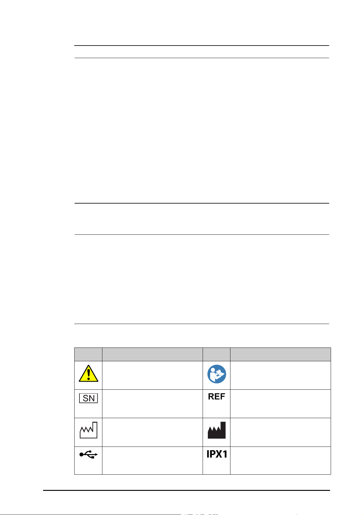
1.1.2 Cautions
CAUTION
NOTE
• Use only parts and accessories specified in this manual.
• Ensure that the equipment is supplied with continuous electric power during work. Sudden power
failure may cause data loss.
• Magnetic and electrical fields are capable of interfering with the proper performance of the
equipment. For this reason make sure that all external devices operated in the vicinity of the
equipment comply with the relevant EMC requirements. Mobile phone, X-ray equipment or MRI
devices are a possible source of interference as they may emit higher levels of electromagnetic
radiation.
• Always install or carry the equipment properly to avoid damage caused by drop, impact, strong
vibration or other mechanical force.
• Dry the equipment immediately in case of rain or water spray.
• Dispose of the package material as per the applicable waste control regulations. Keep it out of
children’s reach.
• At the end of its service life, the equipment, as well as its accessories, must be disposed of in
compliance with the guidelines regulating the disposal of such products. If you have any questions
concerning disposal of the equipment, please contact us.
1.1.3 Notes
• Put the equipment in a location where you can easily view and operate the equipment.
• The equipment use a mains plug as isolation means to the mains power. Do not locate the
equipment in a place difficult to operate the mains plug.
• The typical operator's position is in front of the monitor.
• The software was developed in compliance with IEC60601-1-4. The possibility of hazards arising
from software errors is minimized.
• This manual describes all features and options. Your equipment may not have all of them.
• Keep this manual in the vicinity of the equipment so that it can be obtained conveniently when
needed.
1.2 Equipment Symbols
Symbol Description Symbol Description
General warning sign Refer to instruction manual/booklet
Serial number Catalogue number
Date of manufacture Manufacturer
USB connector Protected against vertically falling water
drops per IEC 60529
BeneVision N22/N19 Patient Monitor Operator’s Manual 1 - 3
Page 28
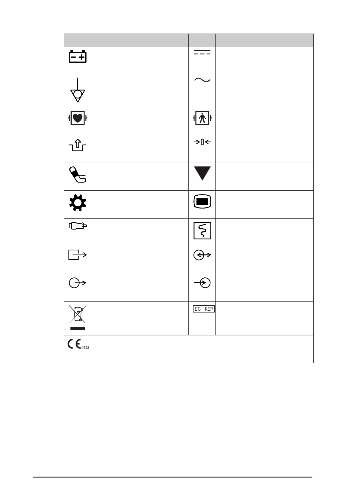
Symbol Description Symbol Description
Battery indicator Direct current
Equipotentiality Alternating current
DEFIBRILLATION-PROOF TYPE CF APPLIED
PAR T
Stop USB Zero key
NIBP start/stop key Calibrate key
Setup menu key Main menu key
Check sensor Graphical record
Gas outlet Input/output
Output Input
DEFIBRILLATION-PROOF TYPE BF APPLIED
PA RT
Dispose of in accordance to your country’s
requirements
The product bears CE mark indicating its conformity with the provisions of the Council Directive 93/42/EEC
concerning medical devices and fulfils the essential requirements of Annex I of this directive.
Note: The product complies with the Council Directive 2011/65/EU.
Authorised representative in the European
Community
1 - 4 BeneVision N22/N19 Patient Monitor Operator’s Manual
Page 29

2 Equipment Introduction
Intended Use. . . . . . . . . . . . . . . . . . . . . . . . . . . . . . . . . . . . . . . . . . . . . . . . . . . . . . . . . . . . . . . . . . . . . . . . . . . . . . . . . . . . . . . . 2-2
Applied Parts . . . . . . . . . . . . . . . . . . . . . . . . . . . . . . . . . . . . . . . . . . . . . . . . . . . . . . . . . . . . . . . . . . . . . . . . . . . . . . . . . . . . . . . 2-2
System Components . . . . . . . . . . . . . . . . . . . . . . . . . . . . . . . . . . . . . . . . . . . . . . . . . . . . . . . . . . . . . . . . . . . . . . . . . . . . . . . . 2-3
BeneVision N22/N19 Patient Monitor Operator’s Manual 2 - 1
Page 30

2.1 Intended Use
WARNING
The BeneVision N22 and N19 patient monitors (N22, N19, or the monitor) are intended to be used for
monitoring, displaying, reviewing, storing, alarming and transferring of multiple physiological parameters
including ECG (3-lead, 5-lead, 6-lead, and 12-lead selectable, arrhythmia detection, ST segment analysis, QT/QTc
monitoring, and heart rate (HR)), respiration (Resp), temperature (Temp), pulse oxygen saturation (SpO2), pulse
rate (PR), non-invasive blood pressure (NIBP), invasive blood pressure (IBP), cardiac output (C.O.), carbon dioxide
(CO
), oxygen (O2), anesthetic gas (AG), impedance cardiograph (ICG), bispectral index (BIS), respiration
2
mechanics (RM), continuous cardiac output (CCO), central venous oxygen saturation (ScvO
electroencephalograph (EEG), neuromuscular transmission (NMT), and regional oxygen saturation (rSO
monitor also provides an interpretation of resting 12-lead ECG.
All the parameters can be monitored on single adult, pediatric, and neonatal patients with the exception of the
following:
■ The ST segment analysis, BIS, RM, CCO, ScvO2 and NMT monitoring are intended for adult and pediatric
patients only.
■ C.O.monitoring is only intended for adult patients.
■ ICG monitoring is only intended for use on patients who meet the following requirements: height 122 to
229cm, weight 30 to 155kg.
This monitor is to be used in healthcare facilities by clinical professionals or under their guidance. It is not
intended for helicopter transport, hospital ambulance, or home use.
),
2
). The
2
• This monitor is intended for use only by clinical professionals or under their guidance. It must only
be used by persons who have received adequate training in its use. Anyone unauthorized or
untrained must not perform any operation on it.
2.2 Applied Parts
The applied parts of the monitor are:
■ ECG electrode and leadwire
■ SpO
■ Tem p probe
■ NIBP cuff
■ IBP transducer
■ C.O. sensor
■ CCO sensor
■ ScvO
■ PiCCO sensor
■ ICG sensor
■ CO
■ AG sampling line, water trap, airway adapter, and mask
sensor
2
sensor
2
sampling line/nasal sampling cannula, water trap, and mask
2
■ RM sensor
■ EEG electrode
■ BIS sensor
■ NMT sensor and electrode
■ rSO
sensor
2
2 - 2 BeneVision N22/N19 Patient Monitor Operator’s Manual
Page 31

2.3 System Components
NOTE
(1) (2)
(3)
(4)
(5) (6) (7) (8) (9)
(10)
(11)
The monitor consists of the main unit, primary display, secondary displays, external modules, satellite module
rack (SMR), input devices, and output devices.
• Your monitor may not include all these components. Contact your local service personnel for the
available components.
2.3.1 Main Unit
The main unit processes data from modules.
2.3.1.1 Main Unit for Combined Installation
If the main unit and the primary display are combinedly installed. It provides the following connectors:
Bottom View:
BeneVision N22/N19 Patient Monitor Operator’s Manual 2 - 3
Page 32

Left View:
(12)
(1) Cable retainer
(2) AC Power input
(3) Nurse call connector (NC)
It is a BNC connector. It connects the monitor to the hospital’s nurse call system through the nurse call cable (PN:
8000-21-10361). Alarms from the monitor are sent to the nurse station through the nurse call system, if
configured to do so.
(4) Satellite module rack connector (SMR1, 2, 3): connects the SMR and T1 docking station.
(5) Equipotential Grounding Terminal
When using the monitor together with other devices, connect their equipotential grounding terminals together
to eliminate the potential difference between them.
(6) Video output connector (VP1): connects the secondary display.
(7) Network Connector (LAN1)
It is a standard RJ45 connector which connects the monitor to the central monitoring system (CMS) or other
network devices.
(8) Network Connector (LAN 2)
Reserved for future use.
(9) Serial bus connectors (MSB1, 2, 3): connect USB devices, for example the keyboard, mouse, and barcode reader. If
independent secondary display is connected, the MSB1 connector is connected to the SBH connector at the rear
of the secondary display to activate the MSB connector connecting the keyboard and mouse for the
independent secondary display.
(10) Network Connector (LAN3)
It is a standard RJ45 connector which connects the iView system to the external network.
(11) Video output connector (VP2): connects the iView display.
2 - 4 BeneVision N22/N19 Patient Monitor Operator’s Manual
Page 33

(12) USB connectors: available only when iView module is configured. They connects USB devices for the iView, for
(1) (2) (3)
example keyboard and mouse.
2.3.1.2 Main Unit for Separate Installation
If the main unit and the primary display are separately installed, besides the connectors described in
2.3.1.1 Main Unit for Combined Installation, the main unit also provides connectors at the rear.
(1) Video output connector (VP3): connects the VP connector on the separated primary display.
(2) Serial bus connector (MSB4): connects the serial bus hub connector (SBH) on the separated
primary display.
(3) Signal input connector (SIG): connects the SIG1 connector on the separated primary display.
2.3.2 Displays
The displays are used to display system information, alarm messages, parameter numerics, waveforms, and so
on. The displays integrate audible and visual alarms and provide USB connectivity. There are two display sizes
available: the 22-inch display and the 19-inch display. The monitor supports a primary display, a secondary
display, and a iView display.
2.3.2.1 Combined Primary Display
The primary display can be installed with or separately from the main unit, either horizontally or vertically.
The following picture shows the indicators and connectors on the primary display when it is installed with the
main unit.
BeneVision N22/N19 Patient Monitor Operator’s Manual 2 - 5
Page 34

(2)(3)
(1)
(5)
(4)
(5)
(4)
(6)
(3)
(2)
(1)
(5)
(5)
(1) Alarm lamp:
When a physiological alarm or technical alarm occurs, this lamp lights and flashes corresponding with the alarm
priority:
◆ High priority alarms: the lamp quickly flashes red.
◆ Medium priority alarms: the lamp slowly flashes yellow.
◆ Low priority alarms: the lamp lights in cyan without flashing.
2 - 6 BeneVision N22/N19 Patient Monitor Operator’s Manual
Page 35

(2) Battery indicator:
VP
MSB 2MSB 1 SBHSIG 1
12V 4.5A
SIG 1 12V 4.5A
VP
(1) (2) (3) (4) (5)
◆ Yellow: the battery is being charged.
◆ Green: the battery is fully charged.
◆ Flashing green: the monitor operates on battery power.
◆ Off: no battery is installed, or the battery is malfunctioning, or the monitor is powered off and no AC power
is connected.
(3) AC power indicator
◆ On: when AC power is connected.
◆ Off: when AC power is not connected.
(4) Power switch
◆ Pressing this switch turns on the monitor.
◆ When the monitor is on, pressing and holding this switch turns off the monitor.
(5) Serial bus connectors (MSB): connect USB devices, for example keyboard, mouse, and barcode reader.
2.3.2.2 Separated Primary Display/Secondary Display
Besides the indicators and connectors, which are the same as those of the combined primary display, the
separated primary display and the secondary display have connectors at the rear.
(1) Serial bus connector (MSB1, MSB2): connect USB devices, for example keyboard, mouse, and barcode reader.
(2) Signal input connector (SIG1): for the separate primary display, it connects the SIG connector at the rear of the
main unit; for the secondary display, it is reserved for future use.
(3) Serial bus hub connector (SBH): connects the MSB1 connector at the bottom of the main unit to activate MSB
connectors for the independent secondary display.
(4) DC-in connector: connects the DC adaptor to run the secondary display.
(5) Video output connector (VP): connects the VP1 connector at the bottom of the main unit.
BeneVision N22/N19 Patient Monitor Operator’s Manual 2 - 7
Page 36

2.3.3 Satellite Module Rack (SMR)
(1)
(2) (3)
The SMR provides interface between the monitor and external modules. The SMR has eight module slots. It is
connected to the main unit through the SMR connector. You can connect up to three SMRs to the monitor.
The following pictures show the indicator and connectors on the SMR.
(1) SMR status indicator: illuminates when the SMR is powered on.
(2) Monitor connector: connects the BeneView monitor.
(3) Monitor connector: connects the BeneVision monitor.
2.3.4 External Modules
The external modules are used to monitor the patient’s physiological parameters, record patient information
and data, and connect external devices. The monitor provides the following modules:
■ Parameter modules: acquires and processes the patient’s data and sends the data to the main unit.
■ Recorder module: prints patient information, parameter measurements and waveforms.
■ BeneLink module: connects external devices. The monitor outputs data from external devices through the
BeneLink module.
2 - 8 BeneVision N22/N19 Patient Monitor Operator’s Manual
Page 37

2.3.4.1 Available Modules
The following table lists available modules.
Module label Part Number Comments
MPM 115-024423-00 MPM-1, integrated ECG, Resp, Mindray SpO
MPM 115-024425-00 MPM-3, integrated ECG, Resp, Nellcor SpO
MPM 115-033829-00 MPM-13, integrated ECG, Resp, Mindray SpO
MPM 115-033830-00 MPM-14, integrated ECG, Resp, Nellcor SpO
SpO
SpO
2
2
115-015008-00 Mindray SpO
115-033641-00 Nellcor SpO
2
2
C.O. 115-013335-00 /
IBP 6800-30-50485 /
BIS 6800-30-50486 /
ICG 115-031389-00 Medis ICG
CCO/SvO
2
115-003480-00 /
PiCCO 115-007270-00 /
ScvO
2
115-007273-00 /
EEG 115-018152-00 /
NMT 115-018518-00 /
rSO
CO
CO
CO
CO
2
2
2
2
2
115-031388-00 /
6800-30-50487 Mainstream CO2, Capnostat
6800-30-50490 Microstream CO2, Oridion
115-027544-00 Sidestream CO2+O2 (paramagnetic), Mindray
115-027545-00 Sidestream CO2+O2 (oxygen sensor), Mindray
RM 115-022808-00 /
, Temp, NIBP
2
, Temp, NIBP
2
, Temp, NIBP, IBP
2
, Temp, NIBP, IBP
2
AG 115-023945-00 AG+O
AG 115-023943-00 AG+O
2
2
+BIS
AG 115-023946-00 AG+BIS
AG 115-023944-00 AG only
BeneLink 115-007276-00 /
/ 115-031386-00 Recorder
You can simultaneously use maximum three IBP modules (besides the IBP of the MPM module) and two
rSO2modules. The other modules can only be used one at a time. Otherwise, the monitor will issue a module
conflict prompt.
For example, if a CO
module is already loaded and then another CO2 module is inserted, the monitor will then
2
prompt module conflict. To solve the problem of module conflict, just remove a module.
BeneVision N22/N19 Patient Monitor Operator’s Manual 2 - 9
Page 38

2.3.4.2 Example Module
(1) (2) (3)
(4)
(5)
(1)
(2)
The parameter modules have similar structure:
■ The parameter label is marked at the upper left corner.
■ Hard keys are located on the upper part.
■ Patient cable connectors are located at the lower part.
We take the MPM module as an example.
(1) Setup hard key: enters or exits the MPM setup menu.
(2) Zero hard key: enters the Zero IBP menu.
(3) Analog out connector: outputs defibrillation synchronization pulse, ECG, and IBP analog
signal.
(4) Module status indicator
◆ On: the module works properly.
◆ Flashing: the module is initializing.
◆ Off: the module is not connected or the module fails.
(5) Patient cable connectors: the MPM module incorporates multiple measurement modules,
including ECG, Resp, SpO
2.3.5 Cable Management Kit
The cable management kit is installed at the bottom of the SMR.
, NIBP, Temp, and IBP.
2
2 - 10 BeneVision N22/N19 Patient Monitor Operator’s Manual
Page 39

2.3.6 Input Devices
The monitor allows data entry through touchscreen, keyboard, mouse, navigation knob, and barcode reader.
The input devices are connected to the monitor, primary and secondary displays through the MSB connector
and connected to the iView module through the USB connectors. You can use separate input devices for the
primary display and secondary display.
2.3.6.1 Touchscreen
Both the primary display and the secondary display are configured with touchscreen.
2.3.6.2 Mouse
You can use Mindray specified mice, wired or wireless, to operate the monitor.
■ The primary display and the secondary display can have independant mouses.
■ When the secondary display is used as an extend dipslay, you can use one mouse to control both the
primary display and the secondary display.
2.3.6.3 Keyboard
You can use Mindray specified keyboards, wired or wireless, to operate the monitor.
(1) Handle: you can place the NIBP cuff on the handle.
(2) Cable hooks: you can put the cables and leadwires on the hooks.
■ The primary display and the secondary display can have independant keyboards.
■ When the secondary display is used as an extend dipslay, you can use one keyboard to control both the
primary display and the secondary display.
2.3.6.4 Navigation Knob
You can use the navigation knob to operate the monitor. The navigation knob is installed at the bottom of the
display.
■ The primary display and the secondary display can have independant navigation knob.
■ When the secondary display is used as an extend dipslay, you can use one navigation knob to control both
the primary display and the secondary display.
There are four keys on the navigation knob:
■ Alarm Reset hard key: acknowledges the on-going alarm.
■ Alarm Pause hard key: pauses the current alarms.
■ Main Menu hard key: enters the main menu.
■ NIBP Start/Stop hard key: starts an NIBP measurement or stops the current NIBP measurement.
BeneVision N22/N19 Patient Monitor Operator’s Manual 2 - 11
Page 40

2.3.6.5 Barcode Reader
You can use Mindray specified barcode reader to enter the patient’s medical record number (MRN).
2.3.7 Printing Devices
You can use the printer and/or recorder to output patient information and data.
2.3.7.1 Recorder
The monitor can be equipped with an external recorder module to output patient data, waveforms, and reports.
To use the recorder, insert the recorder module into the SMR.
2.3.7.2 Printer
The printer can be connected to the monitor through the network to output patient reports.
2 - 12 BeneVision N22/N19 Patient Monitor Operator’s Manual
Page 41

3 Getting Started
Equipment Preparation Safety Information. . . . . . . . . . . . . . . . . . . . . . . . . . . . . . . . . . . . . . . . . . . . . . . . . . . . . . . . . . . 3-2
Monitor Installation . . . . . . . . . . . . . . . . . . . . . . . . . . . . . . . . . . . . . . . . . . . . . . . . . . . . . . . . . . . . . . . . . . . . . . . . . . . . . . . . . 3-2
Setting Up the Equipment. . . . . . . . . . . . . . . . . . . . . . . . . . . . . . . . . . . . . . . . . . . . . . . . . . . . . . . . . . . . . . . . . . . . . . . . . . . 3-3
Turning on the Monitor. . . . . . . . . . . . . . . . . . . . . . . . . . . . . . . . . . . . . . . . . . . . . . . . . . . . . . . . . . . . . . . . . . . . . . . . . . . . . . 3-4
Operation and Navigation . . . . . . . . . . . . . . . . . . . . . . . . . . . . . . . . . . . . . . . . . . . . . . . . . . . . . . . . . . . . . . . . . . . . . . . . . . . 3-4
Screen Display . . . . . . . . . . . . . . . . . . . . . . . . . . . . . . . . . . . . . . . . . . . . . . . . . . . . . . . . . . . . . . . . . . . . . . . . . . . . . . . . . . . . . . 3-5
Operating Modes . . . . . . . . . . . . . . . . . . . . . . . . . . . . . . . . . . . . . . . . . . . . . . . . . . . . . . . . . . . . . . . . . . . . . . . . . . . . . . . . . . . 3-9
Configuring Your Monitor . . . . . . . . . . . . . . . . . . . . . . . . . . . . . . . . . . . . . . . . . . . . . . . . . . . . . . . . . . . . . . . . . . . . . . . . . . 3-12
Starting Monitoring a Patient . . . . . . . . . . . . . . . . . . . . . . . . . . . . . . . . . . . . . . . . . . . . . . . . . . . . . . . . . . . . . . . . . . . . . . . 3-13
Stop a Parameter Measurement . . . . . . . . . . . . . . . . . . . . . . . . . . . . . . . . . . . . . . . . . . . . . . . . . . . . . . . . . . . . . . . . . . . . 3-13
Using the On-Screen Timers . . . . . . . . . . . . . . . . . . . . . . . . . . . . . . . . . . . . . . . . . . . . . . . . . . . . . . . . . . . . . . . . . . . . . . . . 3-15
Using the Secondary Display . . . . . . . . . . . . . . . . . . . . . . . . . . . . . . . . . . . . . . . . . . . . . . . . . . . . . . . . . . . . . . . . . . . . . . . 3-16
Setting Secondary Display Brightness. . . . . . . . . . . . . . . . . . . . . . . . . . . . . . . . . . . . . . . . . . . . . . . . . . . . . . . . . . . . . . . 3-17
Turning Off the Monitor . . . . . . . . . . . . . . . . . . . . . . . . . . . . . . . . . . . . . . . . . . . . . . . . . . . . . . . . . . . . . . . . . . . . . . . . . . . . 3-18
BeneVision N22/N19 Patient Monitor Operator’s Manual 3 - 1
Page 42

3.1 Equipment Preparation Safety Information
WARNING
CAUTION
NOTE
• Use only installation accessories specified by Mindray.
• The equipment software copyright is solely owned by Mindray. No organization or individual shall
resort to modifying, copying, or exchanging it or to any other infringement on it in any form or by
any means without due permission.
• Connect only approved devices to this equipment. Devices connected to the equipment must meet
the requirements of the applicable IEC standards (e.g. IEC 60950 safety standards for information
technology equipment and IEC 60601-1 safety standards for medical electrical equipment). The
system configuration must meet the requirements of the IEC 60601-1 medical electrical systems
standard. Any personnel who connect devices to the equipment’s signal input/output port are
responsible for providing evidence that the safety certification of the devices has been performed in
accordance to the IEC 60601-1. If you have any questions, please contact Mindray.
• If it is not evident from the equipment specifications whether a particular combination with other
devices is hazardous, for example, due to summation of leakage currents, please consult the
manufacturer or an expert in the field. A determination must be made that the proposed
combination will not negatively affect the devices themselves or the patient's safety.
• If the accuracy of any value displayed on the monitor, central station, or printed on a graph strip or
report is questionable, determine the patient’s vital signs by alternative means. Verify that all
equipment is working correctly.
• The equipment should be installed by authorized Mindray personnel.
• When disposing of the packaging material, be sure to observe the applicable waste control
regulations and keep it out of children’s reach.
• Before use, verify whether the packages are intact, especially the packages of single use accessories.
In case of any damage, do not apply it to patients.
• Make sure that the equipment operating environment meets the specific requirements. Otherwise
unexpected consequences, e.g. damage to the equipment, could result.
• Observance of this manual is a prerequisite for proper product performance and correct operation
and ensures patient and operator safety.
• Put the equipment in a location where you can easily view and operate the equipment.
• Keep this manual in the vicinity of the equipment so that it can be conveniently referenced when
needed.
• Save the packing case and packaging material as they can be used if the equipment must be
reshipped.
3.2 Monitor Installation
The monitor can be installed in various ways as required.
■ Wall mount through GCX channel
■ Installed on the medical supply unit
■ Installed on the anesthesia machine
3 - 2 BeneVision N22/N19 Patient Monitor Operator’s Manual
Page 43

3.3 Setting Up the Equipment
WARNING
Observance of this manual is a prerequisite for proper product performance and correct operation. It ensures
patient and operator safety.
3.3.1 Connecting the AC Mains
The monitor is powered by AC power supply. Before connecting the equipment to the AC mains, check that the
voltage and frequency ratings of the power line are the same as those indicated besides the AC power input.
To use the AC power source, follow this procedure:
1. Connect the female end of the power cord with the AC power input.
2. Connect the male end of the power cord with a wall AC outlet.
3. Check that the AC indicator is on.
The AC indicator is off if the AC mains is not connected. When AC mains is connected, the AC indicator is
illuminated in green.
• Always use the accompanying power cord delivered with the monitor.
• Before connecting the equipment to the AC mains, check that the voltage and frequency ratings of
the power line are the same as those indicated besides the AC power input.
• Use the cable retainer to secure the power cord to prevent it from falling off.
• Use the battery if the integrity of the protective earth conductor or the protective earthing system in
the installation is in doubt.
3.3.2 Connecting the Input Devices
Connect the mouse, keyboard, navigation knob, and barcode scanner if necessary.
3.3.3 Connecting the SMR
To connect the SMR, use the SMR cable (PN: 009-005121-00 or 009-005122-00) to connect the monitor
connector on the rear of SMR to the SMR connector on the main unit.
3.3.4 Connecting Modules to the SMR
To connect a module to the SMR, follow this procedure:
1. With the module properly oriented, align the module insertion guide slot with the SMR insertion guide.
Push the module into the SMR until you hear a click.
2. Push the lock at the bottom of the module inwards to lock the module.
BeneVision N22/N19 Patient Monitor Operator’s Manual 3 - 3
Page 44

3.3.5 Removing Modules from the SMR
CAUTION
CAUTION
To remove a module from the SMR, follow this procedure:
1. Pull outwards the lock at the bottom of the module to release the module.
2. Lift the latches at the bottom of the module and slide the module out of the SMR. Hold on the module to
make sure it does not drop when it comes out.
• When removing modules, be careful not to drop them. Always support with one hand while pulling
out with the other.
3.4 Turning on the Monitor
Before turn on the monitor, perform the following inspections:
1. Check the monitor, SMR and modules for any mechanical damage. Make sure that all external cables, plugins and accessories are properly connected.
2. Connect the power cord to the AC power source.
To turn on the monitor, press the power switch. If you are using the secondary display, turn it on too.
3.5 Operation and Navigation
Everything you need to operate the monitor is on its screen. Almost every element on the screen is interactive.
Screen elements include parameter values, waveforms, quick keys, information fields, alarms fields and menus.
Often you can access the same element in different ways. For example, you can access a parameter menu by
selecting corresponding numeric area or waveform area, through the Menu hard key on the parameter
module, or through the Parameter Setup quick key.
3.5.1 Using the Touchscreen
You can use the touchscreen to select a screen element by pressing directly on the monitor’s screen.
To avoid misuse, you can temporarily disable the touchscreen. To do so, hold and press the Main Menu quick
key for five seconds. A padlock symbol displays above the main menu quick key if the touchscreen is
disabled.
The touchscreen lock period is configurable. To do so, follow this procedure:
1. Access Display in either of the following ways:
◆ Select the Screen Setup quick key → select the Display tab.
◆ Select the Main Menu quick key → from the Display column select Display
2. Set Screen Lock Duration.
The touchscreen is enabled when the preset time is reached. If you need to manually enable the touchsceen,
hold and press the Main Menu quick key again.
• If the touchscreen is loose, immediately stop using the monitor and contact the service personnel.
3.5.2 Using the Mouse
You can use the mouse to select a screen element by moving the cursor on the element and then click on it.
Only the left mouse-button can be used. The right mouse-button is disabled.
3 - 4 BeneVision N22/N19 Patient Monitor Operator’s Manual
Page 45

3.5.3 Using the On-Screen Keyboard
(1) (2) (3) (4) (5)
(9)
(6)
(7)
(8)
The on-screen keyboard enables you to enter information:
■ Enter the information by selecting one character after another.
■ Select the Backspace key to delete single characters or select to delete the entire entry.
■ Select the Caps Lock key to access uppercase letters.
■ Select the Enter key to confirm the entry and close the on-screen keyboard.
If a conventional keyboard is connected to the monitor, you can use it instead of or in combination with the onscreen keyboard.
3.5.4 Using the Navigation Knob
You can use the navigation knob to select a menu element by rotating the knob to highlight the element, and
then press down the knob.
3.6 Screen Display
The following figure shows the normal screen:
(1)
Patient information area: displays patient information, including patient category, gender, department, room
number, bed number, and so on. The displayed patient information is configurable. Selecting this area enters the
Patient Management menu. For more information, see 4.3 Managing Patient Information.
(2) The current configuration
(3) Technical alarm information area: displays prompt messages on the above; displays technical alarm messages at
the bottom.
(4) Physiological alarm information area: displays high priority physiological alarms on the above; displays medium
and low priority physiological alarms at the bottom.
(5) System status information area: displays battery status, network status, storage device status, and system time.
For more information, see 3.6.1 On-screen Symbols.
(6) Parameter waveform area: displays parameter waveforms. Select a waveform enters corresponding parameter
menu. For more information, see • ECG is always switched on. You cannot switched it off..
BeneVision N22/N19 Patient Monitor Operator’s Manual 3 - 5
Page 46

(7) Parameter numerics area: displays parameter values, alarm limits, and alarm status. Selecting a parameter
numeric block enters corresponding parameter menu. For more information, see • ECG is always switched on.
You cannot switched it off..
(8) Parameter numerics/waveform area: displays parameter values and waveforms.
(9) Quick key area: displays quick keys.
3.6.1 On-screen Symbols
The following table lists the on-screen symbols displayed on the system status information area:
Symbol Description Symbol Description
Adult, male Adult, female
Pediatric, male Pediatric, female
Neonate, male Neonate, female
Wireless network is connected. The solid part
indicates network signal strength.
Wired network is connected. Wired network is not connected.
All the alarms are paused. Individual physiological alarms are turned off
Audible alarm tones are paused. Audible alarm tones are turned off
Alarms are acknowledged and the alarm
system is reset.
The battery has low power and needs to be
charged.
The battery is being charged. No battery is installed.
Wireless network is not connected.
or the monitor is in the alarm off status.
The battery works correctly. The green
portion represents the remaining charge.
The battery has critically low charge and
needs to be charged immediately. Otherwise,
the monitor will soon automatically shut
down.
3 - 6 BeneVision N22/N19 Patient Monitor Operator’s Manual
Page 47

3.6.2 Menus
(1)
(2)
(2)
(3)
(4)
(5)
(6)
All menus have similar style and structure, see the figure below:
(1) Menu heading
3.6.3 Quick Keys
The monitor provides quick keys for you to quickly access some functions. The quick key area is located at the
bottom of the screen. Normally the quick key area displays 14 quick keys. The Main Menu key is permanently
located the right bottom, and the More key is permanently located at the left bottom. Selecting the More quick
key shows more quick keys. The quick keys displayed on the screen are configurable.
3.6.3.1 Available Quick Keys
The following table shows available quick keys.
Symbol Label Function Symbol Label Func tion
Main Menu Enters the main menu. More Shows more quick keys.
(2) Submenu tabs
(3) Operation buttons
(4) Exit button: closes the current menu page.
(5) Main body area: includes menu items and options.
(6) Switch:
◆ Green: the switch is on.
◆ Gray: the switch is off.
Alarm Enters the Alarm menu. Alarm Reset Acknowledges the
ongoing alarms.
BeneVision N22/N19 Patient Monitor Operator’s Manual 3 - 7
Page 48

Symbol Label Func tion Symbol Label Func tion
Audio Pause Pauses alarm tone. Alarm Pause Pauses the current alarms.
Review Enters the Review menu. Standby Enters the Standby mode.
Patient
Demographics
NIBP Start/
Stop
NIBP STAT Starts a five-minutes
Zero IBP Starts IBP zero calibration. C.O. Measure
PAWP En ters the PAWP screen. Loops Enters the Loops window.
Venipuncture Enters the Venipuncture
Parameters
Setup
Enters the Patient
Management menu.
Starts an NIBP
measurement or stops the
current NIBP
measurement.
continuous NIBP
measurement.
window.
Enters the Parameters
Setup menu.
Screen Setup Enters the Screen Setup
menu.
Stop All Stops all NIBP
measurements.
NIBP Measure Enters the NIBP Measure
menu.
Enters the C.O.
window.
Start TOF Starts/stops TOF
measurement.
Remote View Enters the Remote View
window.
Measure
Manual Event Manually triggers and
saves an event.
OxyCRG Enters the OxyCRG
window.
Privacy Mode Enters the privacy mode. Night Mode Enters the night mode.
CPB Mode Enters the CPB mode. Intubation
Volume Enters the Volu me menu. Freeze Freezes waveforms.
Calculations Enters the Calculations
menu.
Minitrends Enters the Minitrends
screen.
ECG FullScreen
Mode
Load
Configuration
Enters the 12-lead ECG full
screen.
Enters the intubation
mode.
Enters the Load Config
menu.
3 - 8 BeneVision N22/N19 Patient Monitor Operator’s Manual
Page 49

Symbol Label Function Symbol Label Func tion
Print Starts printing a real-time
report.
Unit Enters the Unit menu. Rotate Screen Changes the setting of
ECG Lead/Gain Enters the ECG Lead/Gain
menu to select ECG leads
and waveform size.
3.6.3.2 Configuring the Displayed Quick Keys
To select the quick keys you want to display, follow this procedure:
1. Access Quick Key in either of the following ways:
◆ Select the Screen Setup quick key → the Select Quick Keys tab.
◆ Select the Main Menu quick key → from the Display column select Quick Keys.
2. Select the Current tab to configure the quick keys you want to display on the screen: From the top of this
page, select a block where you want to show a certain quick key, and then select the quick key from the
quick key list. For example, if you want to show the Screen Setup quick key at the first block, select the first
block, and then select Screen Setup from the list.
Record Starts/Stops a recording.
screen orientation.
3. Select the More tab to configure the quick keys you want to display when the More quick key is selected.
3.7 Operating Modes
The monitor provides different operating modes. This section describes the monitoring mode and the standby
mode.
3.7.1 Monitoring Mode
The monitoring mode is the most frequently used clinical mode for patient monitoring. When the monitor is
turned on, it automatically enters the monitoring mode.
3.7.2 Privacy Mode
The privacy mode is a special clinical mode. In the privacy mode, the monitor does not display patient
information and monitoring data. This provides controlled access to patient data and ensures confidentiality.
The privacy mode is only available when the patient admitted by the monitor is also monitored by the CMS. The
monitor continues monitoring the patient, but patient data is only visible at the CMS.
3.7.2.1 Entering the Privacy Mode
To enter the privacy mode, choose either of the following ways:
■ Select the Privacy Mode quick key → select Ok.
■ Select the Main Menu quick key → from the Display column select Privacy Mode → select Ok.
The monitor has the following features after entering the privacy mode:
■ The screen turns blank.
■ Except for the low battery alarm, the monitor inactivate alarm tone and alarm light of all other alarms.
■ The monitor suppresses all system sounds, including heart beat tone, pulse tone, and prompt tone.
BeneVision N22/N19 Patient Monitor Operator’s Manual 3 - 9
Page 50

WARNING
.
NOTE
CAUTION
• In Privacy mode, all audible alarms are suppressed and the alarm light is deactivated at the monitor.
Alarms are presented only at the CMS. Pay attention to potential risk.
• The privacy mode is not available if the Department is set to OR.
• You cannot enter the privacy mode if a low battery alarm occurs.
3.7.2.2 Exiting the Privacy Mode
The monitor automatically exit the privacy mode in any of the following situations:
■ The monitor disconnects from the CMS.
■ The low battery alarm occurs.
You can also operate the touchscreen, mouse, or keyboard to manually exit the privacy mode.
3.7.3 Night Mode
The night mode is a special clinical mode. To avoid disturbing the patient, you can use the night mode.
3.7.3.1 Entering the Night Mode
To enter the night mode, follow this procedure:
1. Select the Night Mode quick key, or select the Main Menu quick key → from the Display column select
Night Mode.
2. Change the night mode settings if necessary.
3. Select Enter Night Mode.
The night mode settings are as follows by default:
■ Brightness: 1
■ Alarm Volume: 2
■ QRS Volume: 1
■ Key Volume: 0
■ NIBP End Tone: Off
■ Stop NIBP: Off
• Verify the night mode settings before entering the night mode. Pay attention to the potential risk if
the setting value is low.
3 - 10 BeneVision N22/N19 Patient Monitor Operator’s Manual
Page 51

3.7.3.2 Exiting the Night Mode
NOTE
WARNING
To cancel the night mode, follow this procedure:
1. Select the Night Mode quick key, or select the Main Menu quick key → from the Display column select
Exit Night Mode.
2. Select Ok.
• If you monitor is connected to the CMS, it automatically exits the night mode when being
disconnected from the CMS.
• The monitor resume the previous settings after exiting the night mode.
3.7.4 Standby Mode
You can temperately stops patient monitoring without switching off the monitor by entering the standby mode.
3.7.4.1 Entering the Standby Mode
1. Select the Standby quick key, or select the Main Menu quick key → from the Patient Management
column select Standby.
2. Set Location to define where the patient is when the monitor enters the standby mode.
3. Select Ok.
The monitor behaves as follows after entering the standby mode:
■ Stops all parameter measurements.
■ Disables all the alarms and prompt messages, except for the battery low alarm.
■ Turns screen brightness to the dimmest after entering the standby mode for 30 seconds.
• Pay attention to the potential risk of placing the monitor to standby. In the standby mode, the
monitor stops all parameter measurements and disable all the alarm indications, except for the
battery low alarm.
3.7.4.2 Changing the Patient Location at Standby
If you need to change the patient’s location, select Location from the Standby screen.
3.7.4.3 Exiting the Standby Mode
To exit the standby mode, choose any of the following ways:
■ Select Resume Monitor to exit the standby mode and resume monitoring the current patient.
■ Select Discharge Patient to discharge the current patient.
■ Select New Patient to exit the standby mode and admit a new patient.
If the monitor automatically enters the standby mode after a patient is discharged, choose any of the following
ways to exit the standby mode:
■ Select New Patient to exit the standby mode and admit a new patient.
■ Select Pre-admit to enter the patient information for preparing to admit a new patient.
BeneVision N22/N19 Patient Monitor Operator’s Manual 3 - 11
Page 52

3.8 Configuring Your Monitor
CAUTION
Configure your monitor before putting it in use.
3.8.1 Selecting the Language
To set the user interface (UI) language, follow this procedure:
1. Select the Main Menu quick key → turn to the third page → from the System column select Maintenance
→ input the required password → select Ok.
2. Select the Other tab.
3. Set Language.
3.8.2 Setting the Screen Orientation
Both the primary display and the secondary display can be installed vertically or horizontally. Set the screen
orientation accordingly. To do so, follow this procedure:
1. Access Display in either of the following ways:
◆ Select the Screen Setup quick key → select the Display tab.
◆ Select the Main Menu quick key → from the Display column select Display.
2. From the Primary Screen block select Screen Orientation to set the screen orientation of the primary
display.
3. If you are using the secondary display, from the Secondary Screen block, select Screen Orientation to set
the screen orientation of the secondary display.
◆ Portrait: if your display is vertically installed, set Screen Orientation to Portrait.
◆ Landscape: if your display is horizontally installed, set Screen Orientation to Landscape.
You can select the Rotate Screen quick key to quickly switch the screen orientation.
3.8.3 Setting the Date and Time
To set the system time, follow this procedure:
1. Select the Main Menu quick key → turn to the third page → from the System column select Time.
2. Set Date and Time.
3. Set Date Format.
4. If you want to use the 12-hour mode, switch off 24 Hour Time.
5. If you want to use daylight saving time, switch on Daylight Saving Time. You can manually switch on or off
the daylight saving time only when the auto daylight saving time function is disabled. For more
information, see 3.8.4 Enabling Auto Daylight Saving Time for details.
If your monitor is connected to a central monitoring system (CMS) or hospital clinical system (HIS), the date and
time are automatically taken from the CMS. In this case, you cannot change the date and time from your monitor.
• Changing the date and time affects the storage of trends and events and may result in loss of data.
3 - 12 BeneVision N22/N19 Patient Monitor Operator’s Manual
Page 53

3.8.4 Enabling Auto Daylight Saving Time
NOTE
By default, you need to manually enable the daylight saving time. To auto start the daylight saving time, follow
this procedure:
1. Select the Main Menu quick key → turn to the third page → from the System column select Maintenance
→ input the required password → select Ok.
2. Select the Time tab.
3. Switch on Auto Daylight Saving Time.
4. Adjust daylight saving time settings as necessary.
• If you enable Auto Daylight Saving Time you cannot manually switch it on or off from the System
Time menu. For more information, see 3.8.3 Setting the Date and Time.
3.8.5 Adjusting the Screen Brightness
The brightness of the primary screen and secondary screen can be adjusted separately. To adjust the screen
brightness, follow this procedure:
1. Access Display in either of the following ways:
◆ Select the Screen Setup quick key → select the Display tab.
◆ Select the Main Menu quick key → from the Display column select Display.
2. From the Primary Screen block, set Brightness for the primary display.
3. From the Secondary Screen block, set Brightness for the secondary display if configured.
3.8.6 Adjusting the Volume
Select the Volum e quick key to set Alarm Volume, QRS Volume, and Key Volume.
3.9 Starting Monitoring a Patient
After turning on your monitor, follow this procedure to monitor a patient:
1. Admit the patient.
2. Check patient settings. Make sure that alarm limits, patient category and paced status, and so on, are
appropriate for your patient. Change them if necessary.
3. Perform desired measurements. For more information, see corresponding measurement chapters.
3.10 Stop a Parameter Measurement
To stop monitoring a parameter, follow this procedure:
1. Remove corresponding sensor from the patient.
2. Disconnect the sensor from the patient cable.
3. Disconnect the patient cable from the parameter module.
4. If you are using the disposable sensor, discard it.
3.11 General Operation
This section describes the operations that are generally used when monitoring a patient.
3.11.1 Switching On or Off a Parameter
A parameter automatically switches on when you insert its module in the SMR. The parameter is automatically
switched off when you remove its module from the SMR. You can also manually switch on or off a parameter
when its module is connected. To do so, follow this procedure:
BeneVision N22/N19 Patient Monitor Operator’s Manual 3 - 13
Page 54

1. Access Parameters On/Off by any of the following ways:
NOTE
NOTE
◆ Select the Screen Setup quick key → select the Parameters On/Off tab.
◆ Select the Main Menu quick key → turn to the second page → from the Parameters column select
Parameters On/Off.
2. Switch on or off desired parameters.
When a parameter is switched off, the monitor stops data acquisition and alarming for this measurement.
• ECG is always switched on. You cannot switched it off.
3.11.2 Displaying Parameter Numerics and Waveforms
You can configure the parameter numerics, waveforms, and their sequence displayed on the normal screen. To
do so, follow this procedure:
1. Access Tile Layout in either of the following ways:
◆ Select the Screen Setup quick key → select the Tile Layout tab.
◆ Select the Main Menu quick key → from the Display column select Tile Layout.
2. Select a parameter numeric area or waveform area, and then from the popup list select an element you
want to display in this area. The parameters and waveforms you did not select will not displayed.
3.11.3 Accessing Parameter Setup Menus
Each parameter has a setup menu in which you can adjust the alarm and parameter settings. You can enter a
parameter setup menu by using any of the following methods:
■ Select the parameter numeric area or waveform area.
■ Press the setup hard key on the module front.
■ Select the Parameter Setup quick key, and then select the desired parameter.
■ Select the Main Menu quick key → turn to the second page → from the Parameters column select Setup
→ select the desired parameter
.
• In this manual, we always use the first method to enter the setup menu. But you can use any method
you prefer.
3.11.4 Choosing a Screen
The monitor enters the normal screen after it is powered on. The normal screen is most frequently used for
patient monitoring. You can also select other screens. To do so, follow this procedure:
1. Access Choose screen in either of the following ways:
◆ Select the Screen Setup quick key.
◆ Select the Main Menu quick key → from the Display column select Choose screen.
2. Select the desired screen.
3.11.5 Selecting the Big Numerics Screen
The big numerics screen displays parameter numerics in big font size. The big numerics screen displays
measurement values and waveforms of up to six parameters. You can configure the parameters and their layout
on the big numeric screen. To do so, follow this procedure:
1. Access Choose screen in either of the following ways:
3 - 14 BeneVision N22/N19 Patient Monitor Operator’s Manual
Page 55

◆ Select the Screen Setup quick key.
NOTE
◆ Select the Main Menu quick key → from the Display column select Choose screen.
2. Select Big Numerics.
3. Select a parameter numeric area or waveform area, and then from the popup list select an element you
want to display in this area.
If you are using the secondary display which displays independantly, you can select parameters for the big
numeric screen of the secondray display.
3.11.6 Changing Measurement Colors
You can set the color of measurement values and waveforms for each parameter. To do so, follow this procedure:
1. Select Main Menu quick key → from the Display column select Param Color.
2. Select the Current tab and set the colors of the currently monitoring measurement values and waveforms.
3. Select the All tab and set the colors of measurement values and waveforms for all parameters.
3.12 Using the On-Screen Timers
The monitor has a Timer function to notify you when a preset time period is expired. You can simultaneously
display up to four timers. You can set each timer independently.
3.12.1 Displaying Timers
To display a timers, follow this procedure:
1. Access Tile Layout in either of the following ways:
◆ Select the Screen Setup quick key → select the Tile Layout tab.
◆ Select the Main Menu quick key → from the Display column select Tile Layout.
2. Click the parameter area where you want to display the timer, and then select a timer from the popup list.
3.12.2 Setting a Timer
From the timer area, select Setup to enter the Timer Setup menu, and then select Direction to define the timer
type.
There are three types of timer:
■ Down: the timer counts down.
■ Up: the timer counts up.
■ System time: the timer displays the system time.
The default type of timer is countdown. For this type of timer, you can set Run Time and Reminder Volume.
For the countdown timer, a progress bar is shown with the run time. When the remaining time is 10 seconds, the
monitor issues a reminder tone and the timer flashes in red, prompting you that the run time is to expire.
• You cannot change timer settings when a timer is running.
3.12.3 Controlling a Timer
The timer provides the following controls:
■ Start/Stop: starts or stops the timer.
■ Clear: clears the timer and end this timer episode.
BeneVision N22/N19 Patient Monitor Operator’s Manual 3 - 15
Page 56

WARNING
• Do not use the timers to schedule critical patient-related tasks.
CAUTION
CAUTION
3.13 Using the Secondary Display
You can connect a secondary display to the monitor. The secondary display has the following features:
■ Runs on independent AC mains through a DC adaptor.
■ Be able to connect independent input devices.
■ Displays parameters readings and waveforms.
■ Provides visual and audible alarm indications.
To use the secondary display, turn it on before turning on the monitor. The secondary display does not support
hot plug. If the secondary display is disconnected from the main unit, the primary display will present an alarm.
• If the secondary display is accidentally power-off, you need to restart the monitor.
3.13.1 Connecting the Secondary Display Power Supply
You need a power adaptor to convert the AC mains to DC so as to power the secondary display. Before
connecting the power adaptor, check that the power adaptor meets the specification.
To connect the power supply, follow this procedure:
1. Connect one end of the power adaptor to the DC-IN connector on the secondary display.
2. Connect the other end of the power adaptor to the AC mains.
3. Check that the AC indicator on the secondary display is on.
• Use only Mindray specified power adaptor.
3.13.2 Changing Secondary Display Settings
You can separately set the orientation, brightness, alarm indications, and the display contents of the secondray
display.
3.13.2.1 Configuring Secondary Display Screen Contents
The contents of the secondary display is configurable. To do so, follow this procedure:
1. Select the Main Menu quick key → turn to the third page → from the System column select Maintenance
→ input the required password → select Ok.
2. Select the Display tab.
3. Set Screen Contents.
◆ Mirrored: The contents of the secondary display is exactly the same with the primary display. The
orientation of the secondary display is also the same with the primary display.
◆ Independent: You can separately configure the contents and layout of the primary display and
secondary display. The independent secondary display cannot share the mouse and keyboard with
the primary display. Separate mouse and keyboard connected to the display‘s MSB connectors is
required.
3 - 16 BeneVision N22/N19 Patient Monitor Operator’s Manual
Page 57

◆ Extended: You can separately configure the contents and layout of the primary display and secondary
NOTE
WARNING
display. The extended secondary display shares the mouse and keyboard with the primary display. You
cannot use separate mouse and keyboard to operate the extend secondary display.
4. If the Screen Contents is set to Extended, set Secondary Screen Location.
3.13.2.2 Enabling Secondary Display Alarm Indications
The secondary display can provide visual and audible indications. This function is disabled by default. To enable
the secondary display to present alarm light and alarm sound, follow this procedure:
1. Select the Main Menu quick key → turn to the third page → from the System column select Maintenance
→ input the required password → select Ok.
2. Select the Display tab.
3. Set Alarm Sound/Light to On.
3.13.2.3 Setting Secondary Display Alarm Light Brightness
The brightness of the secondary display can be set independently. To do so, follow this procedure:
1. Select the Main Menu quick key → turn to the third page → from the System column select Maintenance
→ input the required password → select Ok.
2. Select the Alarm tab→ Others tab.
3. From the Alarm Light Brightness block, set Secondary Display.
3.13.2.4 Setting Secondary Display Orientation
If the secondary display is an independent display or and extend display, you can set its orientation if necessary.
See 3.8.2 Setting the Screen Orientation for details.
• If the secondary display is a mirror display, its orientation is the same with the primary display and
cannot be set separately.
3.13.2.5 Setting Secondary Display Brightness.
See 3.8.5 Adjusting the Screen Brightness for details.
3.14 Using the iView System
The iView system provides a means of running clinical applications on a monitor for obtaining other patient data.
The application data from the iView can show on the monitor’s display or on the iView display.
The iView is pre-installed with the Windows 7 operating system.
For more information on iView, see iView System Operator’s Manual (PN: 046-008469-00).
• Some clinical applications may show data from another patient. Be aware that some of the data on
your patient monitor display may not always be from your patient.
• Applications running on the iView cannot act as a primary alarming device and cannot be relied upon
for alarm notification. There may be no audible or visible indications apart from what is shown on the
screen, and any data shown may be delayed.
BeneVision N22/N19 Patient Monitor Operator’s Manual 3 - 17
Page 58

CAUTION
• Always use AC mains to run the monitor if iView is in use.
CAUTION
NOTE
• Ensure that any software you installed on the iView complies with all relevant local regulations.
3.15 Turning Off the Monitor
Before turn off the monitor, perform the following check:
1. Ensure that the monitoring of the patient has been completed.
2. Disconnect the cables and sensors from the patient.
3. Make sure to save or clear the patient monitoring data as required.
To turn off the monitor, press and hold the power switch for 3 seconds.
To completely disconnect the power supply, unplug the power cord.
• Press and hold the power switch for 15 seconds to forcibly shut down the monitor if it could not be
shut down normally. This may cause loss of patient data.
• The monitor that was switched on prior to a power loss automatically switched on when the power is
restored.
• In case of a temporary power failure, if the power is restored within 30 minutes, monitoring will
resume with all active settings unchanged; if the monitor is without power for more than 30 minutes,
the monitor behaves the same as it is normally turned off.
3 - 18 BeneVision N22/N19 Patient Monitor Operator’s Manual
Page 59

4 Managing Patients
Discharging a Patient. . . . . . . . . . . . . . . . . . . . . . . . . . . . . . . . . . . . . . . . . . . . . . . . . . . . . . . . . . . . . . . . . . . . . . . . . . . . . . . . 4-2
Admitting a Patient . . . . . . . . . . . . . . . . . . . . . . . . . . . . . . . . . . . . . . . . . . . . . . . . . . . . . . . . . . . . . . . . . . . . . . . . . . . . . . . . . 4-2
Managing Patient Information. . . . . . . . . . . . . . . . . . . . . . . . . . . . . . . . . . . . . . . . . . . . . . . . . . . . . . . . . . . . . . . . . . . . . . . 4-3
Transferring Patient Data . . . . . . . . . . . . . . . . . . . . . . . . . . . . . . . . . . . . . . . . . . . . . . . . . . . . . . . . . . . . . . . . . . . . . . . . . . . . 4-5
BeneVision N22/N19 Patient Monitor Operator’s Manual 4 - 1
Page 60

4.1 Discharging a Patient
WARNING
NOTE
Before monitoring a new patient, discharge the previous patient. After the patient is discharged, all patient data,
including patient information, trend data, and physiological alarm information is be deleted from the monitor.
The technical alarms is reset, and monitor settings returns to their defaults. For more information, see 5.3
Setting Default Configuration.
After a patient is discharged, the monitor automatically admit a new patient.
• Always discharge the previous patient before starting monitoring a new patient. Failure to do so can
lead to data being attributed to the wrong patient.
• Discharging a patient deletes all history data from the monitor.
4.1.1 Auto Discharging a Patient after Monitor Power Off
You can let the monitor automatically discharge after the monitor has been switched off for a period of time.
To set the time period of discharging a patient, follow this procedure:
1. Select the Main Menu quick key → turn to the third page → from the System column select Maintenance
→ input the required password → select Ok.
2. Select the Patient Management tab→ select the Discharge tab.
3. Select a time for Auto Discharge When Power Off. The monitor will automatically discharge the patient
when it is turned off for the designated period of time. The default is Never. That is to say the monitor will
not discharge a patient no matter for how long the monitor has been switched off.
4.1.2 Manually Discharging a Patient
Manually discharge a patient using either of the following methods:
■ Select the Patient Demographics quick key → Discharge Patient.
■ Select the Main Menu quick key → from the Patient Management column select Discharge.
Select an item from the Discharge Patient menu:
■ Selecting Ok: discharges the patient and returns to the normal monitoring screen.
■ Selecting Standby, and then selecting Ok: discharges the patient and goes to the standby screen.
■ Selecting Print End Case Report, and then selecting Ok: discharges the patient and prints the end case
report.
4.2 Admitting a Patient
The monitor admits a new patient in the following situations:
■ After a patient is manually discharged, the monitor automatically admit a new patient.
■ After being switched off for the selected time period, the monitor automatically discharge the previous
patient and admit a new patient at startup.
■ If the monitor has not detected certain patient vital signs (ECG, SpO2, PR, RR, NIBP) for 30 minutes, you will
be prompted whether to start monitoring a new patient if any of the above vital signs are detected again.
■ From the standby screen, select New patient.
Always inputs patient information as soon as the patient is admitted. For more information, see 4.3.2 Editing
Patient Information for details.
4 - 2 BeneVision N22/N19 Patient Monitor Operator’s Manual
Page 61

WARNING
• The settings of patient category and paced status always contain a default value, regardless of
NOTE
whether the patient is admitted or not. Check if the setting is correct for your patient.
• For paced patients, you must set Paced to Yes. If it is incorrectly set to No, the monitor could mistake
a pace pulse for a QRS and fail to alarm when the ECG signal is too weak.
• For non-paced patients, you must set Paced to No.
4.3 Managing Patient Information
4.3.1 Entering the Patient Management Menu
Use any of the following methods to enter the Patient Management menu:
■ Select the patient information area at the top left corner of the screen.
■ Select the Patient Demographics quick key.
■ Select the Main Menu quick key → from the Patient Management column select Demographics.
4.3.2 Editing Patient Information
Edit patient information after a patient has been admitted, or when patient information is incomplete, or when
you want to change patient information:
To edit patient information, follow this procedure:
1. Enter the Patient Management menu. For more information, see 4.3.1 Entering the Patient Management
Menu.
2. Edit patient information as required.
If you connect a barcode reader with your monitor, you can scan the patient’s barcode to enter the patient’s
medical record number (MRN).
• The monitor will reload the configuration if you changed the patient category.
4.3.3 Loading Patient Information from the ADT Server
If the monitor is connected with the Admit-Discharge-Transfer (ADT) server through the eGateway. You can load
patient information from ADT server to the monitor.
To load patient information from the ADT server, follow this procedure:
1. Enter the Find Patient menuin either of the following ways:
◆ Select the Main Menu quick key → from the Patient Management column select Find Patient.
◆ Select Find Patient from the Patient Management menu.
2. Input query criteria.
3. Select Query. Then a list pops up, including all the patients that meet the query criteria.
4. Select a patient from the patient list, and then select Import. Corresponding patient information in the
monitor will be updated.
BeneVision N22/N19 Patient Monitor Operator’s Manual 4 - 3
Page 62

NOTE
• You can load patient information from the ADT server only when ADT Query is enabled.
NOTE
NOTE
• Loading patient information from the ADT server updates only patient information in the monitor.
The patient’s monitoring data is not changed and the patient is not discharged.
4.3.4 Changing Patient Management Settings
You can define which items can be displayed and edited from the Patient Management menu. To do so, follow
this procedure:
1. Select the Main Menu quick key → turn to the third page → from the System column select Maintenance
→ input the required password → select Ok.
2. Select the Patient Management tab.
3. Select the fields you want to display in the Patient Management menu.
4. If necessary, select the customized fields and input names for these fields.
If a patient has been admitted, a message Are you sure to discharge the current patient and admit a new
patient? pops up. Then select Ok to clear any previous patient data. If you do not erase data from the previous
patient, the new patient’s data will be saved into the data of the previous patient. The monitor makes no
distinction between the old and the new patient data.
• If the monitor is connected with the CMS, the patient information items and customized fields are
loaded from the CMS.
4.3.5 Setting the Monitor Location
To set the monitor location, follow this procedure:
1. Select the Main Menu quick key → turn to the third page → from the System column select Maintenance
→ input the required password → select Ok.
2. Select the Device Location tab.
3. Set monitor location to Fixed or Unfixed.
4. Input Bed No. and Room No.
◆ If Fixed is selected, the Patient Management menu only displays Bed No. and Room No., but you
cannot change them.
◆ If Unfixed is selected, you can change Bed No. and Room No. from the Patient Management menu.
• If Monitor Location is set to Unfixed, Bed No. and Room No. are cleared each time you discharge a
patient.
4 - 4 BeneVision N22/N19 Patient Monitor Operator’s Manual
Page 63

4.4 Transferring Patient Data
WARNING
NOTE
You can transfer a patient with a BeneView T1 (hereafter referred to T1 ) to another monitor without re-entering
the patient demographic information or changing the settings. Transferring of patient data enables you to
understand the patient’s history condition. The patient data that can be transferred includes: patient
demographics, trend data, alarm events and parameters alarm limits. You can also transfer patient demographic
information, such as patient ID, height, weight, etc. with the MPM.
• Do not discharge a patient before the patient is successfully transferred.
• After a patient is successfully transferred, check if the patient settings (especially patient category,
paced status, alarm limits settings, and etc) on the monitor are appropriate for this patient.
• The system automatically switches on the HR alarm and lethal arrhythmia alarm after transferring
the patient data.
4.4.1 Data Storage Introduction
Familiarizing yourself with the data respectively stored in the patient monitor, T1 or MPM helps you understand
the effects incurred by transferring patients with an MPM or T1.
Type of storage
Data Patient demographics
(Name, Bed No., Gender, etc.)
Trend data Yes No Yes
Calculation data
(Dose calculations,
oxygenation calculations,
etc.)
Event data
(Marked events, alarm
events, etc.)
Settings Monitor settings
(Alarm pause, alarm volume,
etc.)
Parameter settings
(Alarm limits, measurement
setting, etc.)
Can be stored in the
monitor?
Yes Ye s Yes
Yes N o N o
Yes N o Ye s
Yes N o N o
Yes N o Ye s
4.4.2 Setting the Data Transfer Strategy
When T1or MPMis connected to the the monitor, T1 or MPM automatically uploads the data to the monitor if the
patient demographic information in the monitor are consistent with those of in T1 or MPM. However, the
monitor needs a data transfer strategy if the patient demographic information in the monitor are not consistent
with those of in the T1/MPM. To set the data transfer strategy, follow this procedure:
Can be transferred
via MPM?
Can be transferred
via T1?
1. Select the Main Menu quick key → turn to the third page → from the System column select Maintenance
→ input the required password → select Ok.
2. Select the Patient Management tab → select the Transfer tab.
3. Select Data Transfer Strategy.
BeneVision N22/N19 Patient Monitor Operator’s Manual 4 - 5
Page 64

◆ Always Ask: always prompts a dialog box to ask for strategy.
NOTE
◆ Continue Patient in Module: continue to use the patient data in T1/MPM. The monitor discharges
the patient, and automatically admits a new patient and copies all data from T1/MPM.
◆ Continue Patient in Monitor: continue to use the patient data in the monitor. The monitor deletes all
patient data in the T1/MPM and copies all data in the monitor to the T1/MPM.
4.4.3 Transferring Patient Data via T1
To transfer the patient data via T1, insert the T1 into the SMR.
■ If the patient demographics in the monitor are consistent with those of in the T1, the T1 automatically
uploads the data to the monitor.
■ If the patient demographics in the monitor are not consistent with those of in the T1, and Data Transfer
Strategy is set to Always Ask (for more information, see 4.4.2 Setting the Data Transfer Strategy), the
monitor prompts the Select Patient menu automatically. In this case, you need to select an operation (see
the following table) according to the actual situation.
Operations Operation Description Examples of applications
Continue Patient in Monitor Continue to use the patient data in the
monitor. This deletes all patient data in the
T1 and copies all data in the monitor to the
T1.
Continue Patient in Module Continue to use the patient data in T1. The
monitor discharges the patient, and
automatically admits a new patient and
copies all data from T1.
New Patient Select this option if you will not use either
the information in the monitor or that in
the T1. This deletes all data in the monitor
and T1 and lets you admit a new patient on
the monitor. In this case, you need to reenter the patient demographics. The
monitor will restore the settings according
to the patient category.
Same Patient Select this option if the patient information
in the monitor and T1 are different but you
are sure that it is the same patient. This
merges the patient’s trend data in the
monitor and T1 and copies the settings in
T1 to the monitor as well.
1. Replace T1 during patient monitoring.
2. After the patient is admitted, connect the
T1.
You are monitoring a patient using T1, and
you need to transfer the patient, e.g. from a
ward (original monitor) to the operating
room (destination monitor).
Connect the T1 before admitting a new
patient. However, the monitor and/or T1
have stored the previous patient’s data and
settings.
A patient monitored with the T1 is moved
to another department and again moved
back.
However, the patient information stored in
the T1 was altered before connected to the
original monitor.
• If you select Apply Module Settings, the T1 settings can be transferred to the monitor along with the
patient data. For more information, see 4.4.5 Transferring the T1 Settings.
4.4.4 Setting the Length of Data Transferred by T1
When using T1 to transfer the patient data, you can set the data transfer length. To do so, follow this procedure:
1. Select the Main Menu quick key → turn to the third page → from the System column select Maintenance
→ input the required password → select Ok.
2. Select the Patient Management tab → select the Tra nsf er tab.
3. Set Data Transfer Length.
4 - 6 BeneVision N22/N19 Patient Monitor Operator’s Manual
Page 65

4.4.5 Transferring the T1 Settings
When transferring the T1 data, the T1 settings can also be transferred. To to transfer T1 settings, follow this
procedure:
1. Select the Main Menu quick key → turn to the third page → from the System column select Maintenance
→ input the required password → select Ok.
2. Select the Patient Management tab → select the Transfer tab.
3. Select Apply Module Settings.
4.4.6 Transferring Patient Data via MPM
To transfer the patient data via MPM, insert the MPM into the SMR.
■ If the patient demographics in the monitor are consistent with those in the MPM, the MPM automatically
uploads the data to the monitor.
■ If the patient demographics in the monitor are not consistent with those in the MPM, and Data Transfer
Strategy is set to Always Ask (for more information, see 4.4.2 Setting the Data Transfer Strategy, the
monitor prompts the Select Patient menu. In this case, you need to select an operation (see the following
table) according to the actual situation.
Operations Operation Description Examples of applications
Continue Patient in Monitor Continue with the patient data in the
monitor. This deletes all patient
demographics in the MPM and copies the
patient demographics in the monitor to the
MPM.
Continue Patient in Module Continue with the patient data in MPM. The
monitor discharges the patient, and
automatically admits a patient and copies
patient demographics from MPM.
New Patient Select this button if none of the
information is correct. This deletes all data
in the monitor and MPM and lets you admit
a new patient on the monitor. In this case,
you need to re-enter the patient
demographics. The monitor will restore the
settings according to the patient category.
1. Replace MPM during patient monitoring.
2. After the patient is admitted, connect the
MPM.
A patient is monitored using MPM. You
need to transfer the patient, e.g. from a
ward (original monitor) to the operating
room (destination monitor).
Connect the MPM before admitting a new
patient. However, the monitor and/or MPM
store the previous patient’s data and
settings.
BeneVision N22/N19 Patient Monitor Operator’s Manual 4 - 7
Page 66

This page intentionally left blank.
4 - 8 BeneVision N22/N19 Patient Monitor Operator’s Manual
Page 67

5 Managing Configurations
Configuration Introduction . . . . . . . . . . . . . . . . . . . . . . . . . . . . . . . . . . . . . . . . . . . . . . . . . . . . . . . . . . . . . . . . . . . . . . . . . . 5-2
Changing the Department. . . . . . . . . . . . . . . . . . . . . . . . . . . . . . . . . . . . . . . . . . . . . . . . . . . . . . . . . . . . . . . . . . . . . . . . . . . 5-2
Setting Default Configuration . . . . . . . . . . . . . . . . . . . . . . . . . . . . . . . . . . . . . . . . . . . . . . . . . . . . . . . . . . . . . . . . . . . . . . . 5-2
Saving Current Settings . . . . . . . . . . . . . . . . . . . . . . . . . . . . . . . . . . . . . . . . . . . . . . . . . . . . . . . . . . . . . . . . . . . . . . . . . . . . . 5-3
Deleting a Configuration . . . . . . . . . . . . . . . . . . . . . . . . . . . . . . . . . . . . . . . . . . . . . . . . . . . . . . . . . . . . . . . . . . . . . . . . . . . . 5-3
Transferring a Configuration . . . . . . . . . . . . . . . . . . . . . . . . . . . . . . . . . . . . . . . . . . . . . . . . . . . . . . . . . . . . . . . . . . . . . . . . . 5-3
Modifying Configuration Password . . . . . . . . . . . . . . . . . . . . . . . . . . . . . . . . . . . . . . . . . . . . . . . . . . . . . . . . . . . . . . . . . . 5-4
BeneVision N22/N19 Patient Monitor Operator’s Manual 5 - 1
Page 68

5.1 Configuration Introduction
WARNING
CAUTION
When performing continuous monitoring on a patient, the clinical professional often needs to adjust the
monitor’s settings according to the patient’s condition. The collection of all these settings is called a
configuration. The system configuration items can be classified as: parameter configuration items, conventional
configuration items, and user maintenance items. Allowing you to configure the monitor more efficiently, the
monitor provides different sets of configurations to accommodate the varying patient categories and
departments. You can change some settings from a certain set of configuration and then save the changed
configuration as a user configuration.
The default configurations provided for your monitor are department-oriented. You can choose either from:
■ General
■ OR
■ ICU
■ NICU
■ CCU
Each department has three different sets of configurations tailored for adult, pediatric and neonatal patients.
• The configuration management function is password protected. The configuration management
tasks must be performed by clinical professionals.
5.2 Changing the Department
If the current department configuration is not the one you want to view, you can change the department by
following this procedure:
1. Select the Main Menu quick key → turn to the second page → from the Configuration column select
Manage → input the required password → Select Ok.
2. Select Change Department.
3. Select a department.
4. Select Ok.
• Changing the department will delete all current user configurations.
5.3 Setting Default Configuration
The monitor will load the pre-set default configuration in the following cases:
■ A patient is admitted.
■ A patient is discharged.
■ Patient data is cleared.
■ Patient category is changed.
To set the default configuration, follow this procedure:
1. Select the Main Menu quick key → turn to the second page → from the Configuration column select
Manage → input the required password → Select Ok.
2. Select Select Default Config.
5 - 2 BeneVision N22/N19 Patient Monitor Operator’s Manual
Page 69

3. Select Load the Latest Config or Load Specified Config.
NOTE
◆ When you select Load Specified Config, the restored configuration is subject to the patient category
(adult, pediatric or neonate). This configuration can be either factory configuration or a saved user
configuration. As an example, select Default Adult Config and then select Factory Default or user
configuration(s).
◆ When you select Load the Latest Config, the latest configuration is loaded when the monitor is
started or a patient is admitted.
• To identify which configuration is restored when the monitor starts, enter the main screen to check
the prompt information at the lower part of the screen.
5.4 Saving Current Settings
Current settings can be saved as a user configuration. Up to 10 user configurations can be saved.
To save current settings, follow this procedure:
1. Select the Main Menu quick key → turn to the second page → from the Configuration column select
Manage → input the required password → Select Ok.
2. Select Save Current Settings.
3. Input the configuration name.
4. Select Ok to save current settings as a user configuration.
5.5 Deleting a Configuration
To delete a configuration, follow this procedure:
1. Select the Main Menu quick key → turn to the second page → from the Configuration column select
Manage → input the required password → Select Ok.
2. Select Delete Configuration.
3. Select the configuration you want to delete:
◆ In the Delete Configuration menu, selecting Local tab shows the existing user configurations on the
monitor.
◆ In the Delete Configuration menu, selecting USB Drive tab shows the existing user configurations
on the USB drive.
4. Select Delete.
5. Select Ok.
5.6 Transferring a Configuration
When installing several monitors with identical user configurations, it is not necessary to set each unit
separately. Use a USB drive to transfer the configuration from monitor to monitor.
5.6.1 Exporting a Configuration
To export the current monitor’s configuration, follow this procedure:
1. Connect the USB drive to the monitor’s USB port.
2. Select the Main Menu quick key → turn to the second page → from the Configuration column select
Manage → input the required password → Select Ok.
3. Select Export Configuration.
4. Select the configurations and User Maintenance Settings to export.
BeneVision N22/N19 Patient Monitor Operator’s Manual 5 - 3
Page 70

5. Select Export.
NOTE
5.6.2 Importing a Configuration
To import the configuration from the USB drive to the monitor, follow this procedure:
1. Connect the USB drive to the monitor’s USB port.
2. Select the Main Menu quick key → turn to the second page → from the Configuration column select
Manage → input the required password → Select Ok.
3. Select Import Configuration.
4. Select the configurations and User Maintenance Settings to import.
5. Select Import.
5.6.3 Loading a Configuration
You may make changes to some settings during operation. However, these changes or the pre-selected
configuration may not be appropriate for the newly admitted patient. Therefore, the monitor allows you to load
a desired configuration to ensure that all the settings are appropriate for your patient.
To load a configuration, follow this procedure:
1. Select the Main Menu quick key → turn to the second page → from the Configuration column select
Load.
2. Select the desired configuration.
◆ Select the configuration on this monitor in the Local page.
◆ Select the configuration on the USB drive in the USB Drive page.
3. Select Load.
• The monitor may configure some settings by default when you load a configuration of different
software version with the current configuration.
5.7 Modifying Configuration Password
To modify the configuration password, follow this procedure:
1. Select the Main Menu quick key → turn to the second page → from the Configuration column select
Manage → input the required password → Select Ok.
2. Select Modify Password.
3. Input a new password.
4. Select Ok.
5 - 4 BeneVision N22/N19 Patient Monitor Operator’s Manual
Page 71

6 Networked Monitoring
Network Introduction . . . . . . . . . . . . . . . . . . . . . . . . . . . . . . . . . . . . . . . . . . . . . . . . . . . . . . . . . . . . . . . . . . . . . . . . . . . . . . . 6-2
Network Safety Information . . . . . . . . . . . . . . . . . . . . . . . . . . . . . . . . . . . . . . . . . . . . . . . . . . . . . . . . . . . . . . . . . . . . . . . . . 6-2
Connecting the CMS . . . . . . . . . . . . . . . . . . . . . . . . . . . . . . . . . . . . . . . . . . . . . . . . . . . . . . . . . . . . . . . . . . . . . . . . . . . . . . . . 6-2
Connecting the eGateway . . . . . . . . . . . . . . . . . . . . . . . . . . . . . . . . . . . . . . . . . . . . . . . . . . . . . . . . . . . . . . . . . . . . . . . . . . . 6-2
Using the ADT Gateway . . . . . . . . . . . . . . . . . . . . . . . . . . . . . . . . . . . . . . . . . . . . . . . . . . . . . . . . . . . . . . . . . . . . . . . . . . . . . 6-3
Viewing Other Patients . . . . . . . . . . . . . . . . . . . . . . . . . . . . . . . . . . . . . . . . . . . . . . . . . . . . . . . . . . . . . . . . . . . . . . . . . . . . . . 6-3
Configuring the Network . . . . . . . . . . . . . . . . . . . . . . . . . . . . . . . . . . . . . . . . . . . . . . . . . . . . . . . . . . . . . . . . . . . . . . . . . . . . 6-6
BeneVision N22/N19 Patient Monitor Operator’s Manual 6 - 1
Page 72

6.1 Network Introduction
CAUTION
You can connect the monitor to the central monitoring system (CMS), eGateway, and other monitors through
wired LAN or wireless LAN.
6.2 Network Safety Information
• Wireless network designing, deploying, debugging, and maintenance should be executed by
Mindray service personnel or authorized technicians.
• Always set the wireless network according to local wireless regulations.
• Keep network authentication information, for example password, safe, protecting the network from
being accessed by unauthorized users.
• Do not connect non-medical devices to the monitor network.
• If wireless network signal is poor, there may be a risk of CMS data loss.
• RF interference may result in wireless network disconnection.
• Disconnecting from the network may result in CMS data loss and function failure. Check the patient
in case of network disconnection and solve the network problem as soon as possible.
• Ensure that the monitor IP address setting is correct. Changing the network settings may result in
network disconnection. Contact your service personnel if you have any problems on setting the IP
address.
6.3 Connecting the CMS
You can connect the monitor to the BeneVision CMS through wired LAN or wireless LAN. When connected to the
CMS, the system provides the following function.
■ The monitor can transmits parameter values, waveforms, alarm settings, and events to the CMS. From the
CMS, you can check the patient’s monitoring data and alarms.
■ The monitor can transmit parameter values and alarm settings getting from the connected external
devices to the CMS. From the CMS you can check the patient’s monitoring data and alarms obtaining from
the connected external devices.
■ Patient information, alarm settings, and alarm status can be synchronized between the monitor and the
CMS.
■ You can start or stop NIBP measurements from the CMS.
■ In case of network disconnection, the monitor can transmit the offline data to the CMS when network is
reconnected.
For more information on the CMS, see BeneVision Central Monitoring System Operator's Manual (PN: 046-
007687-00).
6.4 Connecting the eGateway
You can connect the monitor to the eGateway through wired LAN or wireless LAN to implement interaction
between the monitor and external devices. When connected to the eGateway, the system provides the following
functions:
■ The monitor can transmit parameter values, waveforms, alarm settings, and events to the eGateway.
■ The monitor can transmit parameter values and alarm settings, getting from the connected external
devices to the eGateway.
■ Clock can be synchronized between the monitor and the eGateway.
6 - 2 BeneVision N22/N19 Patient Monitor Operator’s Manual
Page 73

6.5 Using the ADT Gateway
NOTE
The ADT (admit-discharge-transfer) gateway is normally deployed in the eGateway. You can obtain patient
information from the hospital ADT server through the ADT gateway.
To configure the ADT gateway, follow this procedure:
1. Select the Main Menu quick key → turn to the third page → from the System column select Maintenance
→ input the required password → select Ok.
2. Select the Network Setup tab → ADT tab.
3. Set IP Address and Port for the ADT gateway.
ADT Query is switched on by default. You can load patient information to the monitor from the ADT server
only when this function is enabled.
6.6 Viewing Other Patients
On your monitor, you can observe alarm conditions and view real time physiological data from patients on other
networked monitoring devices.
A device from a remote site is called a remote device or bed, for example, a bedside monitor or a telemetry. You
can simultaneously watch up to 18 remote devices and view full size screen of one device on your monitor.
• You can also view this monitor from remote devices. This monitor can be viewed by at most four
remote devices at the same time.
You can watch the remote devices in the Remote View window, or the alarm watch tiles on the main screen.
6.6.1 Remote View
In the Remote View window, you can view real time parameters and waveforms from one specific device, and
watch the alarms of other monitored devices at the same time.
6.6.1.1 Entering the Remote View Window
To enter the Remote View window, choose one of the following ways:
■ Select the Remote View quick key.
■ Select the bed at the alarm watch tile on the main screen. For more information, see 6.6.2.2 Displaying the
Alarm Watch Tile on the Main Screen for configuring to display the tile on the main screen.
■ Select the Screen Setup quick key → select the Primary Display tab or Secondary Display tab (depends
on which is desirable)→ select the Choose Screen tab → select Remote View.
BeneVision N22/N19 Patient Monitor Operator’s Manual 6 - 3
Page 74

6.6.1.2 About the Remote View
(2)
(3)
(1)
The following figure shows the Remote View window..
(1) Alarm watch area
■ Display all the monitored remote beds.
■ Be able to accommodate up to 18 beds.
■ Each bed displays the room number, bed number, connection status and alarm status. The
background color indicates the alarm status on the corresponding bed.
Background Color Description
Green No alarm is occurring to the bed.
Red The remote device is disconnected or a high priority alarm is occurring. The high
priority alarm currently is the highest alarm level on the bed. If the remote
device is disconnected, the icon is displayed.
Yellow The medium priority alarm is occurring. The medium priority alarm currently is
the highest alarm level on the bed.
Cyan The low priority alarm is occurring. The low priority alarm currently is the highest
alarm level on the bed.
Grey The bed is in the standby mode.
(2) Main body
Display the patient’s information, alarm status and messages, waveforms, measurements, etc. of the
selected bed. This bed is called main bed.
(3)
Up/down arrow
Scroll one step up or down the window to see more measurements that are not in the current view.
6 - 4 BeneVision N22/N19 Patient Monitor Operator’s Manual
Page 75

6.6.1.3 Adding a Bed
NOTE
You need to add the desired remote devices, and then the alarms from these devices can be watched on your
monitor. To add a remote device, follow this procedure:
1. Enter the Select Bed window. To do so, choose either of the following ways:
◆ In the Remote View window, select Select Bed. For more information, see 6.6.1.1 Entering the
Remote View Window for entering the Remote View window.
◆ Select the icon at the alarm watch tile if the tile is configured to display on the main screen.
2. In the Select Bed window, select a desired department. All the beds under this department will be listed.
3. Select a desired tile at the A-W1, A-W2 or A-W3 areas and then select a bed from the bed list. The selected
bed will appear in the tile.
• The added bed is indicated by a √ check mark at the right of the bed list.
6.6.1.4 Removing a Bed
If you do not want to monitor a remote device any longer, you can remove it. To remove a remote device, follow
this procedure:
1. Enter the Select Bed window. Choose either of the following ways:
◆ In the Remote View window, select Select Bed. For more information, see 6.6.1.1 Entering the
Remote View Window for entering the Remote View window.
◆ Select the icon in the alarm watch tile if the tile is configured to display on the main screen.
2. In the Select Bed window, select a bed at the A-W1, A-W2 or A-W3 areas, and then select Clear Bed. If you
want remove all beds, select Clear All Beds.
6.6.1.5 Displaying the Main Bed
In the Remote View window, you can select a bed at the alarm watch area, then the main body of the Remote
View window will display the real time monitoring screen of the device.
6.6.1.6 Saving a Manual Event
You can initiate a manual event by selecting Manual Event in the Remote View window.
The manual event stores in the event review of the corresponding remote device.
6.6.1.7 Resetting Alarms for Remote Devices
You can reset the alarms on the remote devices by selecting Alarm Reset in the Remote View window. This
function needs to be enabled. For more information, see 9.13.4 Resetting Alarms for Remote Devices.
6.6.2 Alarm Watch
The alarm watch function provides the alarm notification by color and sound.
■ The monitor sounds the highest priority alarm tone from all the monitored remote devices.
■ The moitor displays the highest priority alarm in corresponding background color for each bed at following
areas:
◆ At the top of the Remote View. For more information, see 6.6.1.2 About the Remote View for details.
◆ On the main screen. For more information, see 6.6.2.1 About Alarm Watch Tile for details.
BeneVision N22/N19 Patient Monitor Operator’s Manual 6 - 5
Page 76

6.6.2.1 About Alarm Watch Tile
(1)
(5)
(4)
(3)
(2)
The main screen can display up to three alarm watch tiles, namely A-W1, A-W2 and A-W3. Each tile can
accommodate up to six beds.
The following figure shows the alarm watch tiles.
(1) Alarm watch tile label
(2)
Disconnection icon: when the remote device is disconnected, this icon displays at the tile, and the tile
background color is red.
(3)
Select bed icon: select it to enter the Select Bed window.
(4)
More than one bed tile: when more than one bed is assigned to a tile, the tile displays the alarm status,
connection status, etc.
(5)
One bed tile: when only one bed is assigned to a tile, the tile displays the parameter value and alarm
message from this bed, etc.
The alarm watch tile is similar to alarm watch area in the Remote View. For more information, see 6.6.1.2 About
the Remote View.
6.6.2.2 Displaying the Alarm Watch Tile on the Main Screen
To configure the alarm watch tile to be displayed on the monitor’s main screen, follow this procedure:
1. Select the Main Menu quick key → from the Display column select Choose Screen to enter the Screen
Setup menu.
2. Select the Tile Layout tab.
3. Select the numeric area where you want to display the alarm watch tile, and then in the drop-down list,
select Alarm Watch → A-W1, A-W2, or A-W3.
6.7 Configuring the Network
6.7.1 Selecting a Network Type
To select network type, follow this procedure:
1. Select the Main Menu quick key → turn to the third page → from the System column select Maintenance
→ input the required password → select Ok.
2. Select the Network Type tab.
3. Set Monitor to Auto, LAN1, or WLAN according to your network type. The default is Auto, which means
the monitor can automatically identify your network type.
6 - 6 BeneVision N22/N19 Patient Monitor Operator’s Manual
Page 77

6.7.2 Setting the Wired Network
To set the wired network, follow this procedure:
1. Select the Main Menu quick key → turn to the third page → from the System column select Maintenance
→ input the required password → select Ok.
2. Select the Network tab→LAN1 tab.
3. Select how to get the IP address.
◆ Obtain IP Address Automatically: the monitor automatically gets the IP address.
◆ Use the following Address: you need to input the IP address, Subnet mask, and Gateway.
6.7.3 Setting the Wireless Network
To set the wireless network, follow this procedure:
1. Select the Main Menu quick key → turn to the third page → from the System column select Maintenance
→ input the required password → select Ok.
2. Select the Network Setup tab→WLAN.
3. Input SSID, Security, and Password.
4. Select the More WLAN to select how to get the IP address.
◆ Auto Get IP Address: the monitor automatically gets the IP address.
◆ Use the following Address: you need to input the IP address, Subnet mask, and Gateway.
The monitor supports the following security methods: WEP OFF, WEP ON, WPA PSK, WPA TKIP, WPA2 PSK, WPA2
AES, CCKM TKIP, CCKM AES, WPA PSK AES, WPA AES.
Selecting the security method as desired. You may need to set more parameters for some security methods.
6.7.4 Selecting WLAN Band and Channels
The monitor supports 2.4 G and 5 G WLAN. To select WLAN band rate and channels, follow this procedure:
1. Select the Main Menu quick key → turn to the third page → from the System column select Maintenance
→ input the required password → select Ok.
2. Select the Network Setup tab→WLAN tab.
3. Select WLAN Setup from the bottom left corner of the menu.
4. Set Monitor to Auto, 5G, or 2.4G according to the band you are using. The default is Auto, which means
the monitor can automatically identify the WLAN band.
5. Select Auth Server Type to set the type of authentication server.
6. Select BG Channel to set the type of B and G channels.
7. Select A Channel to set the type of A channel.
6.7.5 Managing Certifications
You can delete certifications from the monitor, or import certifications from the USB memory. To do so, follow
this procedure:
1. Select the Main Menu quick key → turn to the third page → from the System column select Maintenance
→ input the required password → select Ok.
2. Select the Network Setup tab→WLAN tab.
3. Select Certification Management from the bottom left corner of the menu.
◆ From the Local tab, select certifications you want to delete from the monitor, and then select Delete.
BeneVision N22/N19 Patient Monitor Operator’s Manual 6 - 7
Page 78

◆ From the USB Drive tab, select certifications you want to import from the USB memory, and then
select Import.
6.7.6 Setting Multicast Parameters
Multicast helps device discovery between monitors and between monitors and CMS. Devices in the same
multicast group can be mutually discovered.
To set multicast parameters, follow this procedure:
1. Select the Main Menu quick key → turn to the third page → from the System column select Maintenance
→ input the required password → select Ok.
2. Select the Network Setup tab→Device Discover tab.
3. Set Multicast TTL.
4. Set Multicast Address.
6.7.7 Setting the CMS IP Address
To set CMS IP address, follow this procedure:
1. Select the Main Menu quick key → turn to the third page → from the System column select Maintenance
→ input the required password → select Ok.
2. Select the Network Setup tab→Device Discover tab.
3. Set Center Station Address.
◆ The Center Station Address is 0.0.0.0 by default. That is to say that the monitor can be admitted by
any CMS.
◆ If Center Station Address is not 0.0.0.0, the monitor can only be admitted by the specified CMS. The
monitor will send unicast presence message to that CMS. If the CMS cannot discover the monitor via
multicast, it can discover the monitor via unicast.
6.7.8 Setting the Network Service Quality Level
To set the quality of service (QoS), follow this procedure:
1. Select the Main Menu quick key → turn to the third page → from the System column select Maintenance
→ input the required password → select Ok.
2. Select the Network Setup tab→QoS tab.
3. Select QoS Level For Realtime Monitoring to set the service quality of network connection for realtime
monitoring, for example parameter measurements and waveforms, alarms, and so on.
4. Select QoS Level For Others to set the service quality of network connection for non-realtime monitoring,
for example history data, printing, and as on.
6 - 8 BeneVision N22/N19 Patient Monitor Operator’s Manual
Page 79

7 Using with the TM80 Telemetry Monitor and
BP10 NIBP Module
Pairing Introduction. . . . . . . . . . . . . . . . . . . . . . . . . . . . . . . . . . . . . . . . . . . . . . . . . . . . . . . . . . . . . . . . . . . . . . . . . . . . . . . . . 7-2
Pairing and Unpairing Symbols . . . . . . . . . . . . . . . . . . . . . . . . . . . . . . . . . . . . . . . . . . . . . . . . . . . . . . . . . . . . . . . . . . . . . . 7-2
Pairing a TM80 with the Monitor . . . . . . . . . . . . . . . . . . . . . . . . . . . . . . . . . . . . . . . . . . . . . . . . . . . . . . . . . . . . . . . . . . . . . 7-3
Unpairing the TM80 and the Monitor . . . . . . . . . . . . . . . . . . . . . . . . . . . . . . . . . . . . . . . . . . . . . . . . . . . . . . . . . . . . . . . . 7-5
Pairing a BP10 with the Monitor . . . . . . . . . . . . . . . . . . . . . . . . . . . . . . . . . . . . . . . . . . . . . . . . . . . . . . . . . . . . . . . . . . . . . 7-6
Unpairing the BP10 and the Monitor . . . . . . . . . . . . . . . . . . . . . . . . . . . . . . . . . . . . . . . . . . . . . . . . . . . . . . . . . . . . . . . . . 7-7
NIBP Measurement in Sequence or ABPM Mode. . . . . . . . . . . . . . . . . . . . . . . . . . . . . . . . . . . . . . . . . . . . . . . . . . . . . . 7-8
Troubleshooting . . . . . . . . . . . . . . . . . . . . . . . . . . . . . . . . . . . . . . . . . . . . . . . . . . . . . . . . . . . . . . . . . . . . . . . . . . . . . . . . . . . . 7-9
BeneVision N22/N19 Patient Monitor Operator’s Manual 7 - 1
Page 80

7.1 Pairing Introduction
You can connect a BeneVision TM80 telemetry monitor (hereinafter called TM80) and a BP10 NIBP module
(hereinafter called BP10) with the monitor to measure ECG, SpO
patients.
The TM80 can be connected with the monitor either via Mindray Patient Area Network (MPAN) or Wi-Fi. The BP10
can be connected with the monitor via MPAN. The process of establishing connection between the TM80 or
BP10 and the monitor is called "pairing”. When the TM80 and BP10 are paired with the monitor, you can view the
measurement data from these devices on the monitor screen.
You can also pair the TM80 with the monitor at the Central Monitoring System (CMS). For details, see BeneVision
Central Monitoring System Operator’s Manual (PN: 046-007687-00). This chapter only describes how to pair a
TM80 with the monitor at the monitor side.
For MPAN specifications, see A.13 MPAN Specifications. For detailed information on TM80, see BeneVision
TM80 Telemetry Monitor Operator’s Manual (PN: 046-007479-00). For detailed information on BP10, see BP10
NIBP Module Operator’s Manual (PN: 046-008269-00).
7.2 Pairing and Unpairing Symbols
The following symbols may appear during and after pairing and unpairing.
Symbol Location Description
, and NIBP of ambulating adult and pediatric
2
■ Monitor’s Wireless Module Menu
■ ECG and SpO
the monitor screen
Monitor’s Wireless Module Menu Indicates that a TM80 or BP10 is paired with the monitor.
■ Monitor’s Wireless Module Menu
■ ECG and SpO
the monitor screen
■ Prompt message area of the TM80
ECG and SpO
monitor screen
Prompt message area of the TM80 Indicates that the TM80 is not connected to the Wi-Fi access
Prompt message area of the TM80 or
BP10
Prompt message area of the TM80 or
BP10
parameter areas on
2
parameter areas on
2
parameter areas on the
2
Indicates that a TM80 or BP10 is found via MPAN or is paired
with the monitor via MPAN.
Indicates that a TM80 is found via Wi-Fi or is paired with the
monitor via Wi-Fi.
Indicates that the Wi-Fi connection between a TM80 and the
monitor is interrupted.
point.
Indicates that the TM80 or BP10 is paired with the monitor via
MPAN.
Indicates that the TM80 or BP10 is not paired with the monitor
via MPAN. Or the TM80 or BP10 is not connected with the
monitor after paring.
7 - 2 BeneVision N22/N19 Patient Monitor Operator’s Manual
Page 81

7.3 Pairing a TM80 with the Monitor
WARNING
NOTE
A TM80 can be paired with the monitor via MPAN or via Wi-Fi. For pairing via MPAN, all data from the TM80 arrive
with a minimal delay on the monitor screen. For pairing via Wi-Fi, all data from the TM80 arrive with a delay of
several seconds on the monitor screen. The system automatically switches MPAN and Wi-Fi to pair the TM80 with
the monitor as below:
■ When a BP10 is not paired with the monitor, the TM80 will be paired with the monitor via MPAN
preferentially.
■ When a BP10 is paired with the monitor, the TM80 can be paired with the monitor via Wi-Fi only.
■ When the TM80 is paired with the monitor via MPAN, if the monitor is paired with a BP10, the TM80 will be
paired with the monitor via Wi-Fi automatically.
7.3.1 Pairing Procedure
Before pairing, configure the wireless network at the TM80 and at the monitor. Ensure that the TM80 and the
monitor are in the same Wi-Fi network.
To pair the TM80 with the monitor, follow this procedure:
1. Select the Main Menu quick key → turn to the second page → from the Parameters column select
Wireless Module. The message Updating... appears, indicating that the wireless module list is being
updated.
2. Select the desired TM80 under the Device Name column of the Wireless Module menu. If the desired
TM80 is not displayed, select Update List.
3. Select Add on the right of the desired TM80.
4. Select Continue Patient in Monitor or Continue Patient in Telemetry.
◆ Continue Patient in Monitor: uses the patient information and parameters settings in the monitor.
These pieces of information and settings will be synchronized to the TM80.
◆ Continue Patient in Telemetry: uses the patient information and parameters settings at the TM80
and CMS. These pieces of information and settings will be synchronized to the monitor.
Upon completion of pairing, the message Connection Completed appears.
• Make sure that the desired TM80 is paired with the monitor.
• When Patient Category is set to Neo, the Wireless Module option is not available in the Parameters
column.
• When a TM80 is paired with a BP10, the TM80 will automatically disconnect with the BP10 once it is
paired with the monitor.
• If you need to change the name of TM80, see BeneVision TM80 Telemetry Monitor Operator’s Manual
(PN: 046-007479-00).
BeneVision N22/N19 Patient Monitor Operator’s Manual 7 - 3
Page 82

7.3.2 System Responses after Pairing a TM80 with the Monitor
CAUTION
NOTE
This section describes system responses at the monitor and at the TM80 after pairing.
7.3.2.1 System Responses at the Monitor after Pairing a TM80 with the Monitor
Once a TM80 is paired successfully with the monitor, the monitor responds as below:
■ In the Wireless Module menu, the Add button on the right of the paired TM80 changes to Remove. The
symbol displays on the left of Remove.
■ If the monitor is configured with a multi-parameter module like MPM and T1 and the ECG and SpO
are valid, ECG and SpO
and SpO
■ The system will automatically switch between MPAN or Wi-Fi to make the TM80 stay connected with the
monitor.
labels are suffixed with “-T”, indicating that measurement values come from the TM80. The or
2
symbol appears above measurement values as shown below.
values from the TM80 are displayed on the monitor screen preferentially. The ECG
2
values
2
• When Wi-Fi signals are weak, the monitor may have the risk of data loss. In this case, the HR value
calculated by the ECG algorithm at the monitor may have deviations.
• If the HR values displayed on the TM80 screen and on the monitor screen are inconsistent, both HR
values are reliable. HR trend, alarms, and arrhythmia are based on the HR value calculated at the
monitor.
7.3.2.2 System Responses at the TM80 after Pairing a TM80 with the Monitor
Once a TM80 is paired successfully with the monitor, the TM80 responds as below:
■ If the TM80 has communicated with the CMS before pairing, it will not communicate with the CMS after
pairing. But the data measured by the TM80 will be sent to the CMS via the paired monitor. The
measurement data from the TM80 will be displayed in the monitor’s patient window at the CMS.
■ If the TM80 is paired with the monitor via MPAN, the symbol will be changed to in the prompt
message area.
■ The TM80 allows you to turn on or off the screen backlight, trigger a nurse call, enter the screen lock
window or the unpair menu. But it does not allow you to change any settings.
7 - 4 BeneVision N22/N19 Patient Monitor Operator’s Manual
Page 83

7.4 Unpairing the TM80 and the Monitor
NOTE
If the patient will no longer be monitored with the TM80, or only with the TM80 and no longer with the monitor,
you need to end the device pairing. You can unpair the TM80 and the monitor either via the monitor or via the
TM80. After unpairing, the CMS will receive data either from the monitor or from the TM80.
7.4.1 Unpairing via the Monitor
To unpair the TM80 and the monitor, follow this procedure:
1. Select the Main Menu quick key → turn to the second page → from the Parameters column select Wire-
less Module.
2. Select the desired TM80 under the Device Name column of the Wireless Module menu.
3. Select Remove.
4. Select Continue Patient in Monitor or Continue Patient in Telemetry.
◆ Continue Patient in Monitor: the monitor disconnects with the TM80 and continues patient
monitoring. The monitor is connected to the CMS to continue patient monitoring. The TM80
discharges the patient. Discharged is displayed on the TM80 screen and Disconnection Completed
is displayed on the monitor screen.
◆ Continue Patient in Telemetry: the monitor disconnects with the TM80 and discharges the patient.
The TM80 is connected to the CMS to continue patient monitoring. Discharged is displayed on the
monitor screen, indicating completion of unpairing.
• When a TM80 is paired with the monitor, discharging a patient from the monitor automatically
unpairs the TM80 with the monitor.
After you select Continue Patient in Monitor, if a multi-parameter module like MPM and T1 is removed from the
monitor, the message Warning: Multi-parameter Module removed. Are you sure you want to enter standby
mode? appears. You need to select whether to put the monitor in standby mode.
◆ Select a patient location and then select Ok. The monitor enters standby mode.
◆ Select No. The monitor does not enter standby mode and continues patient monitoring.
7.4.2 Unpairing via the TM80
To unpair the TM80 and the monitor, follow this procedure:
1. Press the main menu button on the front panel of the TM80.
2. Input the password for the screen lock window. When Screen Lock is set to Off, skip this step.
3. Select Ye s or No in the Unpair window.
◆ Ye s : the TM80 disconnects with the monitor but does not discharge the patient. The monitor
discharges the patient. The TM80 is connected to the CMS to continue patient monitoring.
◆ No: the TM80 disconnects with the monitor and discharges the patient. The monitor does not
discharge the patient and continues patient monitoring. The monitor is connected to the CMS to
continue patient monitoring.
BeneVision N22/N19 Patient Monitor Operator’s Manual 7 - 5
Page 84

7.4.3 System Responses after Unpairing the TM80 and the Monitor
WARNING
NOTE
This section describes system responses at the monitor and at the TM80 after unpairing.
7.4.3.1 System Responses at the Monitor after Unpairing the TM80 and the Monitor
Once the TM80 is unpaired successfully with the monitor, the monitor responds as below:
■ In the Wireless Module menu, the Remove button on the right of the unpaired TM80 changes to Add.
The symbol disappears.
■ The ECG and SpO
measurement values disappears.
labels on the monitor screen are without the“-T”suffix. The or symbol above
2
7.4.3.2 System Responses at the TM80 after Unpairing the TM80 and the Monitor
Once the TM80 is unpaired successfully with the monitor, the TM80 responds as below:
■ If the TM80 is paired with the monitor via MPAN, the symbol will be changed to in the prompt
message area.
■ The TM80 allows all operations.
7.5 Pairing a BP10 with the Monitor
A BP10 can be paired with the monitor only via MPAN.
7.5.1 Pairing Procedure
To pair a BP10 with the monitor, follow this procedure:
1. Press the MPAN button on the right panel of the BP10. The Pairing... message displays in the message area
of the BP10.
2. Select the Main Menu quick key → turn to the second page → select Wireless Module from the Parame-
ters column at the monitor.
3. Select the desired BP10 under the Device Name column of the Wireless Module menu. If the desired BP10
is not displayed, select Update List.
4. Select Add on the right of the desired BP10.
Upon completion of pairing, the message Connection Completed appears.
5. Select the NIBP Start/Stop quick key on the monitor screen to start one NIBP measurement. Verify that the
NIBP measurement values displayed on the monitor screen and on the BP10 screen are consistent and for
the same patient.
• Make sure that the desired BP10 is paired with the monitor.
• When a BP10 is paired with a TM80, the BP10 will automatically disconnect with the TM80 once it is
paired with the monitor.
• If you need to change the name of BP10, see BP10 NIBP Module Operator’s Manual (PN: 046-008269-
00).
• When a BP10 is paired with the monitor, if the BP10 is out of the MPAN coverage area, it will be
disconnected from the monitor automatically. But when it is within the MPAN coverage area again, it
will be reconnected with the monitor automatically.
7 - 6 BeneVision N22/N19 Patient Monitor Operator’s Manual
Page 85

7.5.2 System Responses after Pairing the BP10 with the Monitor
This section describes system responses at the monitor and at the BP10 after pairing.
7.5.2.1 System Responses at the Monitor after Pairing the BP10 with the Monitor
Once a BP10 is paired successfully with the monitor, the monitor responds as below:
■ In the Wireless Module menu, the Add button on the right of the paired BP10 changes to Remove. The
symbol displays on the left of Remove.
■ The NIBP label on the monitor screen is suffixed with “-T”, indicating that measurement values come from
the BP10 device, as shown below.
■ The Sequence and ABPM tabs are added to the NIBP menu. You can perform NIBP measurement in
sequence or ABPM (Ambulatory Blood Pressure Monitoring) mode.
7.5.2.2 System Responses at the BP10 after Pairing the BP10 and the Monitor
Once a BP10 is paired successfully with the monitor, the BP10 responds as below:
■ The symbol is changed to in the prompt message area.
■ The BP10 allows you to start or stop NIBP measurement by pressing the start or stop NIBP button on the
front panel of the BP10. But it does not allow you to change any settings.
7.6 Unpairing the BP10 and the Monitor
You can unpair the BP10 and the monitor either via the monitor or via the BP10.
7.6.1 Unpairing via the Monitor
To unpair the BP10 and the monitor, follow this procedure:
1. Select the Main Menu quick key → turn to the second page → select Wireless Module from the Parame-
ters column.
2. Select the desired BP10.
3. Select Remove.
Upon completion of unpairing, the message Disconnection Completed appears on the monitor screen.
7.6.2 Unpairing via the BP10
To unpair the BP10 and the monitor, press the MPAN button on the right panel of the BP10.
7.6.3 System Responses after Unpairing the BP10 and the Monitor
This section describes system responses at the monitor and at the BP10 after unpairing.
7.6.3.1 System Responses at the Monitor after Unpairing the BP10 and the Monitor
Once a BP10 is unpaired successfully with the monitor, the monitor responds as below:
■ In the Wireless Module menu, the Remove button on the right of the unpaired BP10 changes to Add. The
symbol disappears.
BeneVision N22/N19 Patient Monitor Operator’s Manual 7 - 7
Page 86

■ The NIBP label on the monitor screen is without the“-T”suffix.
■ The Sequence and ABPM tabs are removed from the NIBP menu.
7.6.3.2 System Responses at the BP10 after Unpairing the BP10 and the Monitor
Once a BP10 is unpaired successfully with the monitor, the BP10 responds as below:
■ The symbol is changed to in the prompt message area.
■ The BP10 allows all operations.
7.7 NIBP Measurement in Sequence or ABPM Mode
When a BP10 is paired with the monitor, you can perform NIBP measurements in sequence or ABPM mode. For
detailed information about NIBP measurement, see BP10 NIBP Module Operator’s Manual (PN:046-008269-00).
7.7.1 Performing NIBP Measurement in Sequence Mode
To perform NIBP measurement in sequence mode, follow this procedure:
1. Select the NIBP parameter area on the monitor screen to enter the NIBP menu.
2. Select the Sequence tab.
3. Set Interval and Duration for the desired measurement phases.
4. Select Start NIBP.
Once NIBP measurement is completed, the sequence mode, current measurement phase, interval, and
duration will be displayed on the monitor screen.
7.7.2 Performing NIBP Measurement in ABPM Mode
In ABPM mode, the NIBP measurements are automatically taken according to the configured intervals for the day
and the night.
To perform NIBP measurement in ABPM mode, follow this procedure:
1. Select the NIBP parameter area on the monitor screen to enter the NIBP menu.
2. Select the ABPM tab.
3. Set Start Time and Interval for the day and night.
4. Select Start NIBP.
Once NIBP measurement is completed, the ABPM mode and measurement values will be displayed on the
monitor screen.
7 - 8 BeneVision N22/N19 Patient Monitor Operator’s Manual
Page 87

7.8 Troubleshooting
Problem Possible Cause Corrective Action
Telemetry Disconnected The TM80 is out of the MPAN coverage
area.
The TM80 is out of the Wi-Fi coverage
area.
The TM80 has been powered off. Power on the TM80.
A satellite module rack is not connected
to the monitor properly.
The monitor is not connected to Wi-Fi
network or its wireless network settings
are incorrect.
The TM80 is not connected to Wi-Fi
network or its wireless network settings
are incorrect.
The exchanger network connected by
the TM80 and the monitor does not
support multicast data transfer.
Tel eme try N IBP
Disconnected
The BP10 is out of the MPAN coverage
area.
The BP10 has been powered off. Power on the BP10.
A satellite module rack is not connected
to the monitor properly.
Put the TM80 in the MPAN coverage area.
Put the TM80 in the Wi-Fi coverage area.
Replug the satellite module rack.
Verify that the monitor’s wireless network
settings are correct and the monitor has been
connected to Wi-Fi network.
Verify that the TM80’s wireless network
settings are correct and the TM80 has been
connected to Wi-Fi network.
Contact your service personnel.
Put the BP10 in the MPAN coverage area.
Replug the satellite module rack.
After a TM80 is paired with
the monitor, ECG waves and
Pleth waveform come from
the TM80 are abnormal on
the monitor screen.
The desired BP10 is not
displayed under the
Device Name column of
the Wireless Module
menu.
Wireless signal interference exists.
Wireless signals are weak.
Insufficient network bandwidth or
greater network delay leads to data
transfer delay.
The BP10 is not found. For the BP10, follow Steps 1 to 3 in
■ Put the TM80 in the MPAN or Wi-Fi
coverage area.
■ Check the interference source and
reduce or eliminate interference.
■ Put the TM80 in the MPAN or Wi-Fi
coverage area with strong signals
strength.
■ Remove any metallic obstructs that
stand between the TM80 and the
monitor.
Contact your service personnel.
7.5.1 Pairing Procedure.
BeneVision N22/N19 Patient Monitor Operator’s Manual 7 - 9
Page 88

Problem Possible Cause Corrective Action
The TM80 is prone to offline
occasionally.
The BP10 is prone to offline
occasionally.
Telemetry Low Battery,
Telemetry Battery Depleted
Wireless signal interference exists. ■ Put the TM80 in the MPAN or Wi-Fi
coverage area.
■ Check the interference source and
reduce or eliminate interference.
Wireless signals are weak.
■ Put the TM80 in the MPAN or Wi-Fi
coverage area with strong signals
strength.
■ Remove any metallic obstructs that
stand between the TM80 and the
monitor.
Insufficient network bandwidth or
Contact your service personnel.
greater network delay leads to data
transfer delay.
MPAN signal interference exists.
■ Put the BP10 in the MPAN coverage
area.
■ Check the interference source and
reduce or eliminate interference.
MPAN signals are weak.
■ Put the BP10 in the MPAN coverage
area with strong signals strength.
■ Remove any metallic obstructs that
stand between the BP10 and the
monitor.
The battery charge is low. Replace with a known good battery for the
TM80.
Telemetry NIBP Low Battery,
The battery charge is low. Replace with a known good battery for the
Telemetry NIBP Battery
Depleted
When the TM80 is out of the
MPAN coverage area, it
cannot be connected to the
monitor by automatically
switching to Wi-Fi
connection.
The TM80 is not connected to Wi-Fi
network or its wireless network settings
are incorrect.
The monitor is not connected to Wi-Fi
network or its wireless network settings
are incorrect.
Device Not Found A satellite module rack is not connected
to the monitor properly.
The monitor is not connected to Wi-Fi
network or its wireless network settings
are incorrect.
The wireless network does not support
multicast data transfer.
BP10.
Verify that the TM80’s wireless network
settings are correct and the TM80 has been
connected to Wi-Fi network.
Verify that the monitor’s wireless network
settings are correct and the monitor has been
connected to Wi-Fi network.
Replug the satellite module rack.
Verify that the monitor’s wireless network
settings are correct and the monitor has been
connected to Wi-Fi network.
The wireless network where the monitor and
the TM80 are connected needs to support
multicast data transfer.
7 - 10 BeneVision N22/N19 Patient Monitor Operator’s Manual
Page 89

8 Interfacing with External Devices
BeneLink Introduction. . . . . . . . . . . . . . . . . . . . . . . . . . . . . . . . . . . . . . . . . . . . . . . . . . . . . . . . . . . . . . . . . . . . . . . . . . . . . . . 8-2
BeneLink Safety Information. . . . . . . . . . . . . . . . . . . . . . . . . . . . . . . . . . . . . . . . . . . . . . . . . . . . . . . . . . . . . . . . . . . . . . . . . 8-2
Supported Devices . . . . . . . . . . . . . . . . . . . . . . . . . . . . . . . . . . . . . . . . . . . . . . . . . . . . . . . . . . . . . . . . . . . . . . . . . . . . . . . . . . 8-3
Differences in Displayed Values . . . . . . . . . . . . . . . . . . . . . . . . . . . . . . . . . . . . . . . . . . . . . . . . . . . . . . . . . . . . . . . . . . . . . . 8-3
Connecting an External Device . . . . . . . . . . . . . . . . . . . . . . . . . . . . . . . . . . . . . . . . . . . . . . . . . . . . . . . . . . . . . . . . . . . . . . 8-4
Devices Integrated Window . . . . . . . . . . . . . . . . . . . . . . . . . . . . . . . . . . . . . . . . . . . . . . . . . . . . . . . . . . . . . . . . . . . . . . . . . 8-6
Monitor System Functions. . . . . . . . . . . . . . . . . . . . . . . . . . . . . . . . . . . . . . . . . . . . . . . . . . . . . . . . . . . . . . . . . . . . . . . . . . . 8-7
BeneVision N22/N19 Patient Monitor Operator’s Manual 8 - 1
Page 90

8.1 BeneLink Introduction
WARNING
NOTE
BeneLink module is intended for connecting external devices, such as ventilators and anesthesia machines, to
the monitor. It allows information (patient data, alarms, etc.) from external devices to be displayed, saved,
recorded, printed, or calculated through the monitor. If the monitor is connected with the CMS or eGateway,
information from external devices can also be transmitted to the CMS or eGateway.
8.2 BeneLink Safety Information
• Devices of the same category can not be connected to the BeneLink module simultaneously.
• A patient monitor supports one BeneLink module only.
• The signal labels used on the patient monitor may be different from those given on the external
device.
• The alarms from external devices may be advanced or delayed before transmission to the patient
monitor.
• There can be differences between the alarm priorities displayed on your monitors and the priorities
displayed on external devices interfaced through BeneLink. Please see the list of Output Signals
corresponding with each external device for the alarm priorities used by your patient monitor.
• The alarm messages from external devices are derived from the open protocol of corresponding
external device. For more information about these alarms, please see the operator’s manual of
corresponding devices.
8 - 2 BeneVision N22/N19 Patient Monitor Operator’s Manual
Page 91

8.3 Supported Devices
NOTE
Device Category Model
Anesthesia machine Draeger Fabius GS/Fabius Tiro/Fabius Plus/Primus
Ventilator Carefusion Vela
GE Aestiva 7900/Aestiva 7100/Avance Carestation/Aisys
Mindray A3/A5/A7
Mindray Wato 20/25/30/35/50/55/60/65
Draeger Evita 2
Draeger Evita 4/ Evita2 dura/Evita XL
GE Engström Carestation (Neo), GE Engström Carestation (Pro)
Hamilton G5/C1/C2 /C3/Galileo
Maquet Servo-i/Servo-s
Mindray Syno Vent E3/E5/300
Mindray SV300
Newport E360
Philips Respironics V60
• BeneLink module may support more devices than those listed in the above table. Contact your
service personnel for the most recent information on the supported devices.
8.4 Differences in Displayed Values
In certain cases, there may be differences between the numerics displayed on the monitor and those on external
devices. The table below lists some situations and possible reasons.
Situation Possible Reasons
Some parameter values are displayed as invalid
values on the monitor.
The monitor and external device display parameter
values with different numbers of places of decimals.
Puritan Bennett 840
The patient monitor and the external device may have different
parameter configuration or displaying range of values. If the
patient monitor displays a parameter not configured in the
external device, or a parameter value from the external device
exceeds the displaying range of the monitor, corresponding
parameter value is displayed on the monitor as an invalid value.
The monitor displays parameter values from the external device
based on the monitor displaying rules. Same parameter value is
displayed differently when the monitor and the external device
adopts different numbers of places of decimals.
Non-continuously measured values and
continuously measured values have the same
displaying mode in the patient monitor.
Parameter values displayed on the patient monitor
and those displayed in the external device are
slightly different.
For non-continuously measured values, the monitor displays the
latest measured values until a new measurement is taken by the
external device.
Some parameter values are converted to different units when
transmitted to the monitor for calculations. Sometimes, values
from the external device may be advanced or delayed before
transmission to the patient monitor.
BeneVision N22/N19 Patient Monitor Operator’s Manual 8 - 3
Page 92

NOTE
• When the pressure units are converted among cmH
(5)
(6)
(4)
(3)
(2)
(1)
unchanged, for example, 1cmH2O=1hPa=1mbar, which may differ from some external devices.
8.5 Connecting an External Device
An external device is connected to the BeneLink module through an ID adapter. The ID adapter supports only its
matching device.
O, hPa and mbar, the parameter values remain
2
(1) BeneLink Module (2) Label
(3) RJ45 connecting cable (4) ID Adapter
(5) External device (6) Serial port adapting cable (optional)
To connect an external device, follow this procedure:
1. Insert the BeneLink module into the SMR.
2. Connect the ID adapter that matches the external device to the BeneLink module with an RJ45 connecting
cable.
3. Plug the ID adapter into the RS232 port on the external device. Some external devices may have ports
incompatible with the ID adapter. In this case, a serial port adapting cable is required.
4. Stick a device name label to the RJ45 connecting cable at the end close to the BeneLink module. When the
BeneLink module is connected to several external devices, you can tell devices easily with these labels.
5. Switch on the external device.
After the external device is connected to the monitor, the indicators on both the ID adapter and the BeneLink
module illuminate to show that the monitor successfully communicates with the external device.
8 - 4 BeneVision N22/N19 Patient Monitor Operator’s Manual
Page 93

CAUTION
• First installation and debugging should be executed by Mindray service personnel or authorized
technician.
• Please check the compatibility of the external device and the ID adapter before connection.
Otherwise, unpredictable system failure may be resulted.
• Ports on the BeneLink module are not conventional network connectors. They are intended for
connecting with the serial port of designated devices only. Do not connect them to public network
interfaces.
8.5.1 Configuring the ID Adapter
The ID adapter has already been correctly configured before leaving the factory. If you want to re-configure the
ID adapter, follow this procedure.
1. Select the Main Menu quick key → turn to the third page → from the System column select Maintenance
→ input the required password → select Ok.
2. Select Upgrade ID module.
3. Select Benelink Module Port to define which port the RJ45 connecting cable is connected to. You must
connect the RJ45 connecting cable to the selected port when re-configuring the ID adapter. Otherwise, ID
adapter re-configuration will fail.
4. Select ID to configure a new ID to the ID adapter.
8.5.2 ID Adapter IDs
External Device ID for ID adapter Type of serial port adapting cable
Anesthesia machine
Draeger Fabius GS/Plus/Tiro 4446BBBA Fabius GS: No need to use the adapting
cable.The ID adapter can be plugged into the
serial port of the external device directly.
Fabius Plus: Type C
Fabius Tiro: Type C
GE Avance Carestation /Aisys 4F41B0BF Type D
GE Aestiva 7100/7900 4F37B0C9 Type D
Mindray Wato20/25/30/35/50/55/
60/65
Mindray A3/A5/A7
Vent ilat or
Carefusion Vela 564ca9b4 Type E
Draeger Evita 2 / Evita 2 dura /
Evita 4/ Evita XL
Draeger Primus 4450BBB0 Type C
GE Engström Carestation (Neo), GE
Engström Carestation (Pro)
4D52B2AE No need to use the adapting cable: the ID
adapter can be plugged into the serial port of
the external device directly.
4434BBCC Type B
4F45B0BB Type B
Hamilton C2 3270CD90 Type B
Hamilton G5 (protocol Block) 3542CABE Type B
Hamilton G5 (protocol Polling) 3550CAB0 Type B
Hamilton Galileo 4750B8B0 Type B
BeneVision N22/N19 Patient Monitor Operator’s Manual 8 - 5
Page 94

External Device ID for ID adapter Type of serial port adapting cable
Maquet Flow-i 4D46B2BA Type B
Maquet Servo-i/Servo-s 4D53B2AD Type B
Mindray E3/E5 4D56B2AA No need to use the adapting cable: the ID
Mindray SV300
Newport E360 4E50B1B0 Type B
adapter can be plugged into the serial port of
the external device directly.
Philips Respironics V60 VPRT: 5637A9C9
SDNA:5636A9CA
Puritan Bennett 840 SNDF: 5042AFBE(recommended)
SNDA: 5031AFCF(support less
parameters than protocol SNDF)
TOF-Watch® SX 5457ABA9 Type C
TCM CombiM/TCM TOSCA 5443ABBD Type C
Serial port adapting cable PN Remark
Type A 009-001767-00 Male to female
Type B 009-001768-00 Male to male
Type C 009-001769-00 Male to male
Type D 009-002943-00 9-pin to 15-pin
Type E 009-004613-00 9-pin to RJ45 connector
8.6 Devices Integrated Window
You can view the information of external devices from the Integrated Devices window. The Integrated Devices
window provides information of both individual device and multi devices. In the individual device menu, you can
select Select Parameter, Unit and Alarm to set the parameters to be displayed, parameter units and view the
alarm list.
Type B
No need to use the adapting cable: the ID
adapter can be plugged into the serial port of
the external device directly.
The parameters in the Integrated Devices window are displayed in the order of priorities. If the window cannot
display all the selected parameters, only parameters with higher priorities are displayed. Please see the following
sections for parameter priorities.
■ For the parameters measured by the external device, the measurements display directly after the parameter
labels.
8 - 6 BeneVision N22/N19 Patient Monitor Operator’s Manual
Page 95

■ For the parameters controlled by the external device, the settings are enclosed in parenthesis after
NOTE
parameter labels.
■ For the parameters measured and controlled by the external device, measurements and settings are
displayed after parameter labels, and settings are also enclosed in parenthesis. For example, PEEP 18 (20), in
which PEEP is parameter label, 18 is the measurement, and (20) is the setting.
8.7 Monitor System Functions
This section describes the monitor system function when external devices are connected.
8.7.1 Alarms
The monitor does not display realtime alarms from external devices. However, you can view the current alarm list
of corresponding device by selecting Alarm from the individual device window. The alarm priority is defined by
“*” before each alarm message. An alarm list can display up to 100 alarm messages.
8.7.2 Data Storage
The monitor saves parameters trends and alarm events from external devices. You can review these data in the
Graphic Trends menu and Events menu, parameters from external devices are displayed in white.
• Parameters from external devices are saved and displayed according to the time of the monitor.
8.7.3 Recording and Printing
You can record and print Information from external devices both in realtime and in graphic and tabular trends
from the monitor. Besides, the monitor can also record the frozen parameters of the external device.
BeneVision N22/N19 Patient Monitor Operator’s Manual 8 - 7
Page 96

This page intentionally left blank.
8 - 8 BeneVision N22/N19 Patient Monitor Operator’s Manual
Page 97

9Alarms
Alarm Introduction . . . . . . . . . . . . . . . . . . . . . . . . . . . . . . . . . . . . . . . . . . . . . . . . . . . . . . . . . . . . . . . . . . . . . . . . . . . . . . . . . . 9-2
Alarm Safety Information . . . . . . . . . . . . . . . . . . . . . . . . . . . . . . . . . . . . . . . . . . . . . . . . . . . . . . . . . . . . . . . . . . . . . . . . . . . . 9-2
Understanding the Alarms. . . . . . . . . . . . . . . . . . . . . . . . . . . . . . . . . . . . . . . . . . . . . . . . . . . . . . . . . . . . . . . . . . . . . . . . . . . 9-2
Accessing Help when Occur . . . . . . . . . . . . . . . . . . . . . . . . . . . . . . . . . . . . . . . . . . . . . . . . . . . . . . . . . . . . . . . . . . . . . . . . . 9-4
Checking Physiological Alarm List. . . . . . . . . . . . . . . . . . . . . . . . . . . . . . . . . . . . . . . . . . . . . . . . . . . . . . . . . . . . . . . . . . . . 9-4
Changing Alarm Settings . . . . . . . . . . . . . . . . . . . . . . . . . . . . . . . . . . . . . . . . . . . . . . . . . . . . . . . . . . . . . . . . . . . . . . . . . . . . 9-4
Pausing Alarms/Pausing Alarm Tones . . . . . . . . . . . . . . . . . . . . . . . . . . . . . . . . . . . . . . . . . . . . . . . . . . . . . . . . . . . . . . . 9-11
Resetting Alarms . . . . . . . . . . . . . . . . . . . . . . . . . . . . . . . . . . . . . . . . . . . . . . . . . . . . . . . . . . . . . . . . . . . . . . . . . . . . . . . . . . . 9-13
Latching Alarms. . . . . . . . . . . . . . . . . . . . . . . . . . . . . . . . . . . . . . . . . . . . . . . . . . . . . . . . . . . . . . . . . . . . . . . . . . . . . . . . . . . . 9-14
Nurse Call. . . . . . . . . . . . . . . . . . . . . . . . . . . . . . . . . . . . . . . . . . . . . . . . . . . . . . . . . . . . . . . . . . . . . . . . . . . . . . . . . . . . . . . . . . 9-14
CPB Mode. . . . . . . . . . . . . . . . . . . . . . . . . . . . . . . . . . . . . . . . . . . . . . . . . . . . . . . . . . . . . . . . . . . . . . . . . . . . . . . . . . . . . . . . . . 9-15
Intubation Mode . . . . . . . . . . . . . . . . . . . . . . . . . . . . . . . . . . . . . . . . . . . . . . . . . . . . . . . . . . . . . . . . . . . . . . . . . . . . . . . . . . . 9-15
Managing Alarms from Remote Devices. . . . . . . . . . . . . . . . . . . . . . . . . . . . . . . . . . . . . . . . . . . . . . . . . . . . . . . . . . . . . 9-16
Testing Alarms . . . . . . . . . . . . . . . . . . . . . . . . . . . . . . . . . . . . . . . . . . . . . . . . . . . . . . . . . . . . . . . . . . . . . . . . . . . . . . . . . . . . . 9-18
Actions When an Alarm Occurs . . . . . . . . . . . . . . . . . . . . . . . . . . . . . . . . . . . . . . . . . . . . . . . . . . . . . . . . . . . . . . . . . . . . . 9-18
BeneVision N22/N19 Patient Monitor Operator’s Manual 9 - 1
Page 98

9.1 Alarm Introduction
WARNING
This chapter descirbes alarm functions and alarm settings.
9.2 Alarm Safety Information
• A potential hazard can exist if different alarm presets and default configuration settings are used for
the same or similar equipment in the same care area, for example an intensive care unit or cardiac
operating room.
• If your monitor is connected to the central monitoring system (CMS) or other monitors, alarms can
be presented and controlled remotely. Remote suspension, inhibition, or reset of monitor alarms via
the CMS or other monitors may cause a potential hazard. For more information, see the operator’s
manuals of the CMS and the other monitors.
• The monitors in your care area may each have different alarm settings to suit different patients.
Always check that the alarm settings are appropriate for your patient before start monitoring.
Always make sure that necessary alarm limits are active and set according to the patient's clinical
condition.
• Make sure that the alarm limit settings are appropriate for your patient before monitoring a patient.
• Setting alarm limits to extreme values may cause the alarm system to become ineffective. For
example, high oxygen levels may predispose a premature infant to retrolental fibroplasia. If this is a
consideration do not set the SpO
alarm off.
high alarm limit to 100%, which is equivalent to switching the
2
• When the alarm sound is switched off, the monitor gives no alarm tones even if a new alarm occurs.
Be careful about whether to switch off the alarm sound or not. When the alarms are off or while
alarm audio is paused either temporarily or indefinitely, observe the patient frequently.
• When monitoring patients that are not continuously attended by a clinical operator, properly
configure the alarm system and adjust alarm settings as per the patient's condition.
• Do not rely exclusively on the audible alarm system for monitoring. Adjustment of alarm volume to a
low level may result in a hazard to the patient. Always make sure that the audio alarm volume level is
adequate in your care environment. Always keep the patient under close surveillance.
9.3 Understanding the Alarms
9.3.1 Alarm Categories
The monitor has two different types of alarms: physiological alarms and technical alarms.
■ Physiological alarms are triggered by patient measurement exceeding the parameter limits, or by an
abnormal patient conditions.
■ Technical alarms are triggered by an electrical, mechanical, or other monitor failure, or by failure of a
sensors or components. Technical alarm conditions may also be caused when an algorithm cannot classify
or interpret the available data.
Apart from the physiological and technical alarms, the monitor can also prompt some messages telling the
system status or patient status.
9 - 2 BeneVision N22/N19 Patient Monitor Operator’s Manual
Page 99

9.3.2 Alarm Priorities
NOTE
By severity, the alarms are classified into the following priority levels:
■ High priority alarms: indicates a life threatening situation or a severe device malfunction. High priority
alarms require an immediate response.
■ Medium priority alarms: indicates abnormal vital signs or a device malfunction. Medium priority alarms
require a prompt response.
■ Low priority alarms: indicate a discomfort condition, a device malfunction, or an improper operation. Low
priority alarms require you to be aware of this condition.
■ Messages: provides additional information on the patient or the equipment.
9.3.3 Alarm Indicators
When an alarm occurs, the monitor indicates it to you through visual or audible alarm indications. For more
information, see the following table.
Alarm Indicator High Priority
Alarm
Alarm lamp Red Yellow Cyan None None
Audibl
e tone
pattern
Alarm message Black text inside
Alarm priority
indicator
ISO Repeat pattern
of 2 × 5 beep
tones
Mode 1 Repeat pattern
of high-pitched
3-beep tones
Mode 2 Repeat pattern
of high-pitched
3-beep tones
a red box
*** ** * None The indicator shows in
Medium
Priority Alarm
Repeat pattern
of 3-beep tones
Repeat pattern
of 2-beep tones
Repeat pattern
of 2-beep tones
Black text inside
a yellow box
Low Priority
Alarm
1-beep tone None None
Low-pitched 1beep tone
Low-pitched 1beep tone
Black text inside
a cyan box
Message Comments
None
None
White
text
Alarm messages are
displayed in the alarm
information area at the
top of the screen. You
can select the alarm
messages to show the
alarm list.
front of corresponding
alarm message.
Parameter value Black text inside
a flashing red
box
Black text inside
a flashing
yellow box
Black text
inside a flashing
cyan box
None None
• When multiple alarms of different priority levels occur simultaneously, the monitor select the alarm
of the highest priority to light the alarm lamp andissue the alarm tone.
• When multiple alarms of different priority levels occur simultaneously and should be displayed in
the same area, the monitor only displays the messages of the highest priority alarm.
• When multiple alarms of the same priority levels occur simultaneously and should be displayed in
the same area, all the alarm messages are displayed circularly.
BeneVision N22/N19 Patient Monitor Operator’s Manual 9 - 3
Page 100

9.3.4 Alarm Status Symbols
NOTE
Apart from the alarm indicators as described in 9.3.3 Alarm Indicators, the monitor uses the following symbols
to indicate the alarm status:
Alarm pause: indicates that all the alarms are paused.
Alarm off: indicates that individual measurement alarms are turned off or the system is in the
alarm off status.
Audio pause: indicates that audible alarm tones are paused.
Audio off: indicates that audible alarm tones are turned off.
Alarm reset: indicates that alarms are acknowledged and the alarm system is reset.
9.4 Accessing Help when Occur
In the technical alarm list, alarm messages followed by Detail include help messages or pictures to help you
identify the problem. To access the help, follow this procedure:
1. Select the technical alarm information area to enter the Alarms window.
2. Select the Technical Alarms tab.
3. From the alarm list select the desired alarm.
• You can find help for the alarms whose alarm messages are followed by “Detail”.
9.5 Checking Physiological Alarm List
To check the physiological alarm list, follow this procedure:
1. Select the physiological alarm information area to enter the Alarms window.
2. Select the Physiological Alarms tab.
9.6 Changing Alarm Settings
9.6.1 Setting Parameter Alarm Properties
To set parameter alarm properties, follow this procedure:
1. Access the Limits page in either of the following WAYS:
◆ Select the Alarm quick key.
◆ Select the Main Menu quick key → from the Alarm column select Limits.
2. Select a parameter tab and perform the following settings:
◆ Switch on or off measurement alarms.
◆ Set the upper and lower alarm limits.
◆ Set the alarm priority.
◆ Enable or disable alarm recordings.
You can also change the alarm properties of individual parameter from corresponding parameter menu.
9 - 4 BeneVision N22/N19 Patient Monitor Operator’s Manual
 Loading...