

Page 1

BeneView T8
Patient Monitor
Service Manual
Page 2

Page 3

Intellectual Property Statement
SHENZHEN MINDRAY BIO-MEDICAL ELECTRONICS CO., LTD. (hereinafter called
Mindray) owns the intellectual property rights to this product and this manual. This manual
may refer to information protected by copyrights or patents and does not convey any license
under the patent rights of Mindray, nor the rights of others. Mindray does not assume any
liability arising out of any infringements of patents or other rights of third parties.
Mindray intends to maintain the contents of this manual as confidential information.
Disclosure of the information in this manual in any manner whatsoever without the written
permission of Mindray is strictly forbidden. Release, amendment, reproduction, distribution,
rent, adaption and translation of this manual in any manner whatsoever without the written
permission of Mindray is strictly forbidden.
, , and are the registered trademarks or
trademarks owned by Mindray in China and other countries. All other trademarks that appear
in this manual are used only for editorial purposes without the intention of improperly using
them. They are the property of their respective owners.
Contents of this manual are subject to changes without prior notice.
Revision History
This manual has a revision number. This revision number changes whenever the manual is
updated due to software or technical specification change. Contents of this manual are subject
to change without prior notice.
Revision number: 9.0
Release time: February 2012
© 2006-2012 Shenzhen Mindray Bio-Medical Electronics Co., Ltd. All rights reserved.
I
Page 4

FOR YOUR NOTES
II
Page 5

Preface
Manual Purpose
This manual provides detailed information about the assembling, dissembling, testing and
troubleshooting of the equipment to support effective troubleshooting and repair. It is not
intended to be a comprehensive, in-depth explanation of the product architecture or technical
implementation. Observance of the manual is a prerequisite for proper equipment
maintenance and prevents equipment damage and personnel injury.
This manual is based on the maximum configuration; Therefore, some contents may not
apply to your monitor. If you have any question, please contact our Customer Service
Department.
Intended Audience
This manual is for biomedical engineers, authorized technicians or service representatives
responsible for troubleshooting, repairing and maintaining the patient monitors.
III
Page 6

Abbreviations
Abbreviations used in this manual are:
MPM multi-parameter module
SMR satellite module rack
CMS central monitoring system
PCB printed circuit board
Passwords
A password may be required to access different modes within the monitor. The passwords are
listed below:
User maintenance: 888888 (User adjustable)
Factory maintenance: 332888
Demo mode: 2088
Configuration mode: 315666 (User adjustable)
IV
Page 7

Contents
1 Safety................................................................................................................................. 1-1
1.1 Safety Information ..........................................................................................................1-1
1.1.1 DANGER ........................................................................................................... 1-2
1.1.2 Warnings............................................................................................................. 1-2
1.1.3 Cautions ............................................................................................................. 1-2
1.1.4 Notes .................................................................................................................. 1-3
1.2 Equipment Symbols ........................................................................................................ 1-3
2 Theory of Operation ........................................................................................................ 2-1
2.1 Introduction..................................................................................................................... 2-1
2.2 System Connections........................................................................................................ 2-2
2.2.1 Mounting the Patient Monitor............................................................................ 2-2
2.2.2 Connectors for Peripheral Devices..................................................................... 2-3
2.3 Main Unit ........................................................................................................................ 2-4
2.3.1 Input System ...................................................................................................... 2-5
2.3.2 Output System.................................................................................................... 2-6
2.3.3 Processing and Communications System........................................................... 2-7
2.3.4 Power Management System............................................................................... 2-9
2.3.5 Equipment Interface System ............................................................................ 2-12
2.4 Parameter Module ......................................................................................................... 2-14
2.4.1 Module Infrared Communication Board .......................................................... 2-14
2.4.2 Module Power Board ....................................................................................... 2-14
2.4.3 Parameter Board............................................................................................... 2-14
2.5 Satellite Module Rack................................................................................................... 2-15
2.6 BeneLink Module.......................................................................................................... 2-16
3 Testing and Maintenance................................................................................................. 3-1
3.1 Introduction..................................................................................................................... 3-1
3.1.1 Test Equipment................................................................................................... 3-1
3.1.2 Test Report ......................................................................................................... 3-2
3.1.3 Preventative Maintenance .................................................................................. 3-2
3.1.4 Recommended Frequency.................................................................................. 3-2
3.2 Preventative Maintenance Procedures ............................................................................ 3-4
3.2.1 Visual Inspection ................................................................................................ 3-4
3.2.2 NIBP Tests.......................................................................................................... 3-5
3.2.3 Sidestream and Microstream CO
3.2.4 AG Tests........................................................................................................... 3-10
3.2.5 Preventative maintenance test report................................................................ 3-13
Module Tests................................................ 3-8
2
1
Page 8

3.3 Power On Test ............................................................................................................... 3-14
3.4 Module Performance Tests ............................................................................................ 3-15
3.4.1 ECG Tests......................................................................................................... 3-15
3.4.2 Resp Performance Test ..................................................................................... 3-16
3.4.3 SpO
Test.......................................................................................................... 3-16
2
3.4.4 NIBP Tests........................................................................................................ 3-17
3.4.5 Temp Test......................................................................................................... 3-17
3.4.6 IBP Tests........................................................................................................... 3-17
3.4.7 C.O. Test........................................................................................................... 3-19
3.4.8 Mainstream CO
3.4.9 Sidestream and Microstream CO
Tests...................................................................................... 3-20
2
Module Tests.............................................. 3-21
2
3.4.10 AG Tests......................................................................................................... 3-21
3.4.11 ICG Test ......................................................................................................... 3-22
3.4.12 BIS Test.......................................................................................................... 3-23
3.4.13 RM Test.......................................................................................................... 3-24
3.4.14 CCO/SvO
Tests ............................................................................................. 3-25
2
3.4.15 PiCCO Tests ................................................................................................... 3-26
3.4.16 ScvO
Tests .................................................................................................... 3-27
2
3.5 Nurse Call Relay Performance Test .............................................................................. 3-28
3.6 Analog Output Performance Test .................................................................................. 3-28
3.7 Electrical Safety Test..................................................................................................... 3-29
3.8 Touchscreen Calibration................................................................................................ 3-29
3.9 Recorder Check............................................................................................................. 3-29
3.10 Network Print Test ...................................................................................................... 3-30
3.10.1 Equipment Connection and Setup .................................................................. 3-30
3.10.2 Print Function Test ......................................................................................... 3-30
3.11 BeneLink Module Check............................................................................................. 3-31
3.11.1 Device Connection and Setup ........................................................................ 3-31
3.11.2 Device Integration Function Test ................................................................... 3-33
3.11.3 Installation and Test Report............................................................................ 3-35
3.12 Battery Check.............................................................................................................. 3-36
3.13 Imbedded PC System Maintenance............................................................................. 3-37
3.13.1 Making USB Startup Disk.............................................................................. 3-37
3.13.2 Restoring the System...................................................................................... 3-39
3.14 Factory Maintenance................................................................................................... 3-42
3.14.1 Accessing Factory Maintenance Menu........................................................... 3-42
3.14.2 Drawing Waves .............................................................................................. 3-42
3.14.3 Recorder ......................................................................................................... 3-42
3.14.4 Software Version ............................................................................................ 3-43
3.14.5 Monitor Information....................................................................................... 3-44
3.14.6 Calibrate NIBP............................................................................................... 3-44
4 Troubleshooting................................................................................................................ 4-1
4.1 Introduction..................................................................................................................... 4-1
2
Page 9

4.2 Part Replacement ............................................................................................................4-1
4.3 Patient Monitor Status Check.......................................................................................... 4-1
4.4 Software Version Check .................................................................................................. 4-2
4.5 Technical Alarm Check ................................................................................................... 4-2
4.6 Troubleshooting Guide.................................................................................................... 4-2
4.6.1 Power On/Off Failures ....................................................................................... 4-2
4.6.2 Display Failures ................................................................................................. 4-3
4.6.3 Module Rack Failures ........................................................................................ 4-4
4.6.4 Alarm Problems.................................................................................................. 4-6
4.6.5 Button and Knob Failures .................................................................................. 4-7
4.6.6 Recorder Failures ............................................................................................... 4-7
4.6.7 Interface Failures................................................................................................ 4-8
4.6.8 CF Card Problems.............................................................................................. 4-9
4.6.9 Power Supply Failures ....................................................................................... 4-9
4.6.10 Network Related Problems..............................................................................4-11
4.6.11 Software Upgrade Problems........................................................................... 4-12
4.6.12 Technical Alarm Messages............................................................................. 4-12
4.6.13 M51A Self Test Information........................................................................... 4-12
4.6.14 Device Integration Failures ............................................................................ 4-13
5 Repair and Disassembly ..................................................................................................5-1
5.1 Tools................................................................................................................................ 5-1
5.2 Preparations for Disassembly.......................................................................................... 5-1
5.3 Basic Disassembly .......................................................................................................... 5-2
5.3.1 Disconnecting the Base ...................................................................................... 5-2
5.3.2 Separating the Front and Rear Half of the Monitor............................................ 5-4
5.4 Further Disassembly........................................................................................................ 5-6
5.4.1 Removing the Power Switch & LED Board ...................................................... 5-6
5.4.2 Disconnecting the Encoder Assembly................................................................ 5-7
5.4.3 Removing the Button Board............................................................................... 5-7
5.4.4 Removing the Touchscreen Control Board ........................................................ 5-8
5.4.5 Removing the Inverter........................................................................................ 5-9
5.4.6 Removing the LCD Screen .............................................................................. 5-10
5.4.7 Removing the Alarm Lamp Board ................................................................... 5-12
5.4.8 Removing the Wireless AP............................................................................... 5-13
5.4.9 Removing the CF Assembly............................................................................. 5-15
5.4.10 Removing the Main Board............................................................................. 5-16
5.4.11 Removing the Fan .......................................................................................... 5-18
5.4.12 Removing the Speaker ................................................................................... 5-18
5.4.13 Removing the Interface Board Assembly....................................................... 5-19
5.4.14 Removing the CIS Assembly ......................................................................... 5-20
5.4.15 Removing the Power Supply Assembly ......................................................... 5-23
5.4.16 Removing the Integral Module Rack ............................................................. 5-26
5.4.17 Removing the Recorder.................................................................................. 5-30
3
Page 10

5.5 Removing the SMR Assembly ...................................................................................... 5-35
5.6 Disassembling Modules ................................................................................................ 5-39
5.6.1 Disassembling the ICG Module ....................................................................... 5-39
5.6.2 Disassembling CO
Module ............................................................................. 5-42
2
5.6.3 Disassembling the BeneLink Module .............................................................. 5-48
5.6.4 Disassembling the New MPM Module ............................................................ 5-51
6 Parts .................................................................................................................................. 6-1
6.1 Introduction..................................................................................................................... 6-1
6.2 Main Unit ........................................................................................................................ 6-2
6.3 Base Assembly ................................................................................................................ 6-3
6.4 Front housing Assembly.................................................................................................. 6-4
6.4.1 17” LCD with Anti-glare Screen........................................................................ 6-4
6.4.2 17” LCD Touchscreen........................................................................................ 6-6
6.5 Rear Housing Assembly.................................................................................................. 6-8
6.5.1 Rear Housing Assembly ..................................................................................... 6-8
6.5.2 Power module................................................................................................... 6-10
6.5.3 Integral Module Rack....................................................................................... 6-12
6.5.4 Interface Board Assembly ................................................................................ 6-13
6.5.5 Main Support Assembly................................................................................... 6-15
6.5.6 Main Control Board Assembly......................................................................... 6-17
6.5.7 6800 Internal Wireless AP Assembly ............................................................... 6-18
6.5.8 Others............................................................................................................... 6-18
6.6 SMR Assembly ............................................................................................................. 6-20
6.6.1 SMR Assembly................................................................................................. 6-20
6.6.2 SMR Inside Assembly...................................................................................... 6-21
6.7 Parameter Modules........................................................................................................ 6-22
6.7.1 MPM Module................................................................................................... 6-22
6.7.2 New MPM Module .......................................................................................... 6-23
6.7.3 C.O. Module..................................................................................................... 6-25
6.7.4 RM Module ...................................................................................................... 6-27
6.7.5 ICG Module ..................................................................................................... 6-28
6.7.6 AG Module....................................................................................................... 6-30
6.7.7 BIS Module ...................................................................................................... 6-32
6.7.8 IBP Module ...................................................................................................... 6-34
6.7.9 Mindray CO
6.7.10 Oridion CO
Module....................................................................................... 6-35
2
Module ...................................................................................... 6-37
2
6.7.11 CCO Module .................................................................................................. 6-38
6.7.12 PiCCO Module............................................................................................... 6-40
6.7.13 ScvO
Module ................................................................................................ 6-41
2
6.7.14 BeneLink Module........................................................................................... 6-43
6.8 Remote Display Box ..................................................................................................... 6-45
6.9 Wireless AP................................................................................................................... 6-46
6.10 Replaceable Parts ........................................................................................................ 6-47
4
Page 11

6.10.1 Main Unit ....................................................................................................... 6-47
6.10.2 SMR ............................................................................................................... 6-49
6.10.3 Parameter Modules......................................................................................... 6-49
6.10.4 Cables............................................................................................................. 6-50
7 Upgrade............................................................................................................................. 7-1
7.1 Introduction..................................................................................................................... 7-1
7.2 Upgrading Parameter Modules........................................................................................ 7-2
7.3 Upgrading Functional Assemblies .................................................................................. 7-4
7.3.1 Upgrading SMR ................................................................................................. 7-4
7.3.2 Upgrading Wireless Network Function.............................................................. 7-4
7.3.3 Upgrading Recorder ........................................................................................... 7-5
7.3.4 Upgrading Analog Output.................................................................................. 7-5
7.3.5 Upgrading CIS ................................................................................................... 7-5
7.4 Upgrading Software ........................................................................................................ 7-6
7.4.1 How to Upgrade Software.................................................................................. 7-8
A Electrical Safety Inspection........................................................................................... A-1
A.1 Power Cord Plug ........................................................................................................... A-2
A.2 Device Enclosure and Accessories................................................................................ A-2
A.3 Device Labeling ............................................................................................................ A-3
A.4 Protective Earth Resistance........................................................................................... A-3
A.5 Earth Leakage Test ........................................................................................................ A-5
A.6 Patient Leakage Current................................................................................................ A-6
A.7 Mains on Applied Part Leakage .................................................................................... A-8
A.8 Patient Auxiliary Current .............................................................................................A-11
A.9 Functional test ............................................................................................................. A-12
5
Page 12

FOR YOUR NOTES
6
Page 13

1 Safety
1.1 Safety Information
DANGER
z Indicates an imminent hazard that, if not avoided, will result in death or serious
injury.
WARNING
z Indicates a potential hazard or unsafe practice that, if not avoided, could result in
death or serious injury.
CAUTION
z Indicates a potential hazard or unsafe practice that, if not avoided, could result in
minor personal injury or product/property damage.
NOTE
z Provides application tips or other useful information to ensure that you get the
most from your product.
1-1
Page 14

1.1.1 DANGER
There are no dangers that refer to the product in general. Specific “Danger” statements may
be given in the respective sections of this manual.
1.1.2 Warnings
WARNING
z All installation operations, expansions, changes, modifications and repairs of this
product are conducted by Mindray authorized personnel.
z There is high voltage inside the equipment. Never disassemble the equipment
before it is disconnected from the AC power source.
z When you disassemble/reassemble a parameter module, a patient leakage cu rrent
test must be performed before it is used again for monitoring.
z The equipment must be connected to a properly installed power outlet with
protective earth contacts only. If the installation does not provide for a protective
earth conductor, disconnect it from the power line and operate it on battery power,
if possible.
z Dispose of the package material, observing the applicable waste control regulations
and keeping it out of children’s reach.
1.1.3 Cautions
CAUTION
z Make sure that no electromagnetic radiation interferes with the performance of the
equipment when preparing to carry out performance tests. Mobile phone, X-ray
equipment or MRI devices are a possible source of interference as they may emit
higher levels of electromagnetic radiation.
z Before connecting the equipment to the power line, check that the voltage and
frequency ratings of the power line are the same as those indicated on the
equipment’s label or in this manual.
z Protect the equipment from damage caused by drop, impact, strong vibration or
other mechanical force during servicing.
1-2
Page 15
1.1.4 Notes
NOTE
z Refer to Operation Manual for detailed operation and other information.
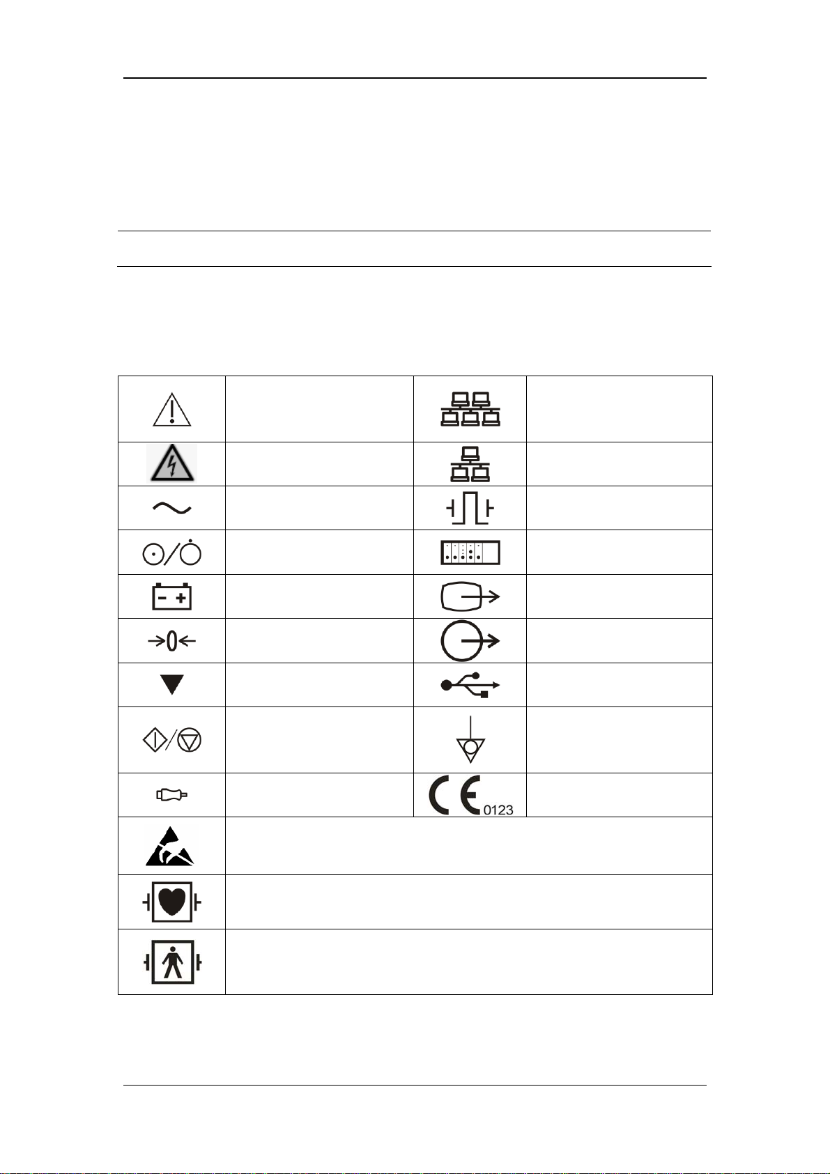
1.2 Equipment Symbols
Attention: Consult
accompanying documents
(this manual).
CIS connector
Danger: High-voltage
Alternating current(AC)
Power ON/OFF
Battery indication
Zero key
Calibrate key
Measure/Standby
Check sensor
ESD warning symbol for Electrostatic sensitive devices.
Network connector
Defibrillator connector
Connector for satellite
module rack
Video output
Auxiliary output connector
USB connector
Equipotential terminal
CE marking
Type CF applied part. Defibrillator-proof protection against electric shock.
Type BF applied part. Defibrillator-proof protection against electric shock.
1-3
Page 16

FOR YOUR NOTES
1-4
Page 17

2 Theory of Operation
2.1 Introduction
This patient monitor is designed to monitor a fixed set of physiological parameters including
ECG, heart rate (HR), respiration (Resp), temperature (Temp), SpO
non-invasive blood pressure (NIBP), invasive blood pressure (IBP), cardiac output (C.O.),
carbon dioxide (CO
bispectral index (BIS), respiration mechanics (RM), continuous cardiac output (PiCCO), and
central venous oxygen saturation (ScvO
), oxygen (O2), anesthetic gas (AG), impedance cardiograph (ICG),
2
).
2
, pulse rate (PR),
2
The patient monitor also:
Provides audible and visual alarm indications in case of patient or equipment problems.
Enables displaying, reviewing, storing and transferring of real-time data.
Incorporates multiple input devices such as buttons, knob, touchscreen, keyboard and
mouse.
Interfaces a clinical information system or central monitoring system.
Enables program upgrade over the network.
Integrates the information of other devices, which include but are not restricted to
anesthesia machine and ventilator.
2-1
Page 18

2.2 System Connections
2.2.1 Mounting the Patient Monitor
The patient monitor can be mounted on a wall bracket or on a trolley support. The wall
bracket or trolley support can be ordered optionally. Each type of mounting bracket is
delivered with a complete set of mounting hardware and instructions. Refer to the
documentation delivered with the mounting hardware for instructions on assembling mounts.
CAUTION
z Use mounting brackets we supply or approve. If other compatible mounting
bracket is used, be sure it can be safely used on the patient monitor.
z The mounting bracket should be installed by our qualified service personnel, or
engineers who have adequate knowledge on it.
z If other mounting solution is used, the installation personnel and the customer
should verify if it can be safely used on the patient monitor, and the customer
assume the responsibility for any risk resulting from that.
2-2
Page 19
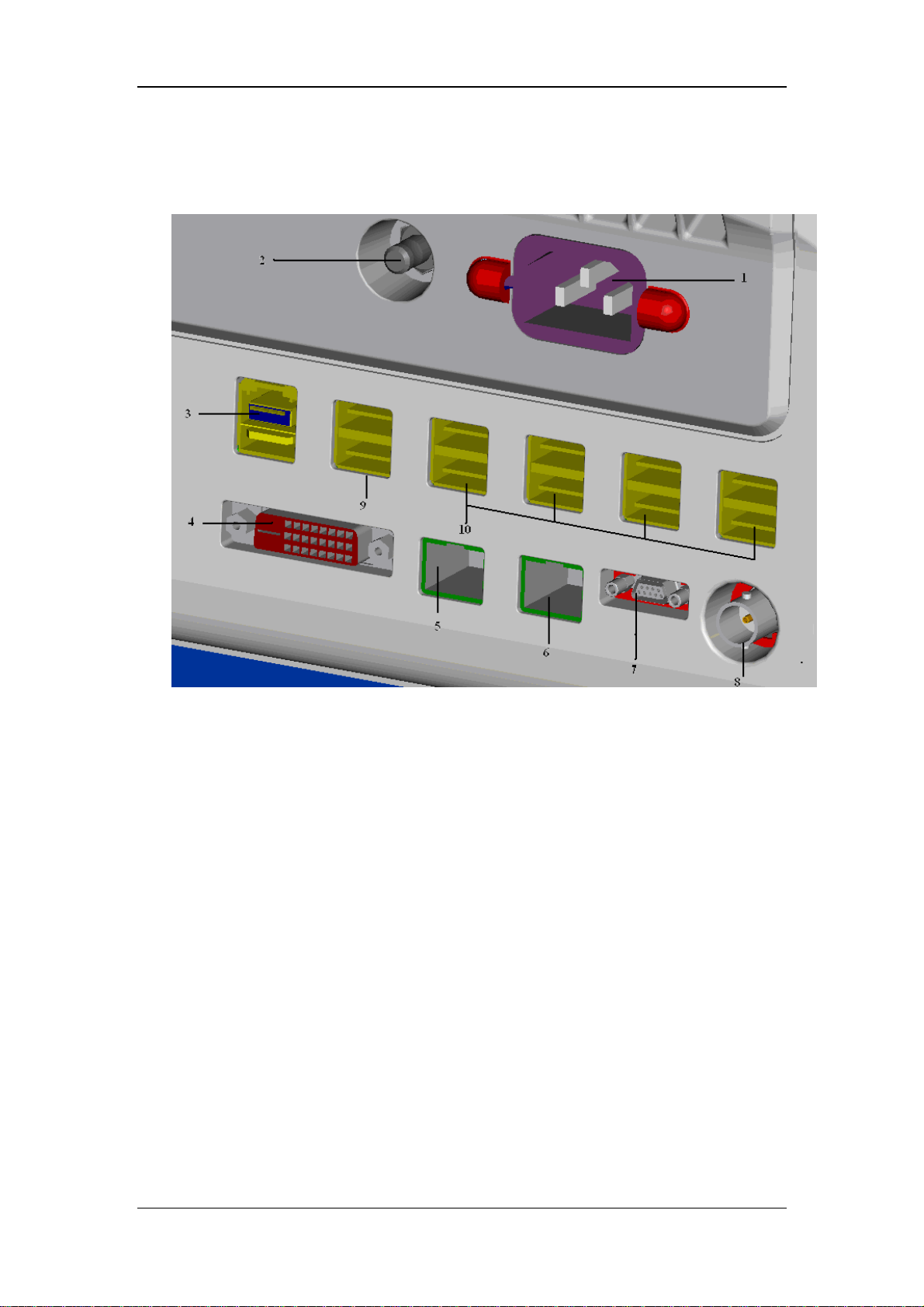
2.2.2 Connectors for Peripheral Devices
On the back of the patient monitor you will find all connectors for peripheral devices.
1. AC Power Connector: used to connect an AC power source (100 to 240 VAC, 50/60Hz).
2. Equipotential Terminal: used to connect the equipotential terminal of other equipment,
eliminating potential difference between different pieces of equipment.
3. SMR Connector: It outputs a 12V DC, used to connect the SMR.
4. Video Output: It is a DVI-D connector used to connect a secondary display.
5. CIS Connector: It is a RJ45 connector used to connect a CIS.
6. Network Connector: It is a RJ45 connector used to connect an ethernet network or a PC.
7. Analog Output and Defibrillator Connector: It is a Micro-D connector used to output
analog signals and defibrillator synchronization signals.
8. Auxi Output Connector: It is a BNC connector used to output nurse call signals.
9. Secondary USB Connector: used to connect the mouse and keyboard of the secondary
display.
10. General USB Connector: used to connect any USB-compatible peripheral device.
2-3
Page 20
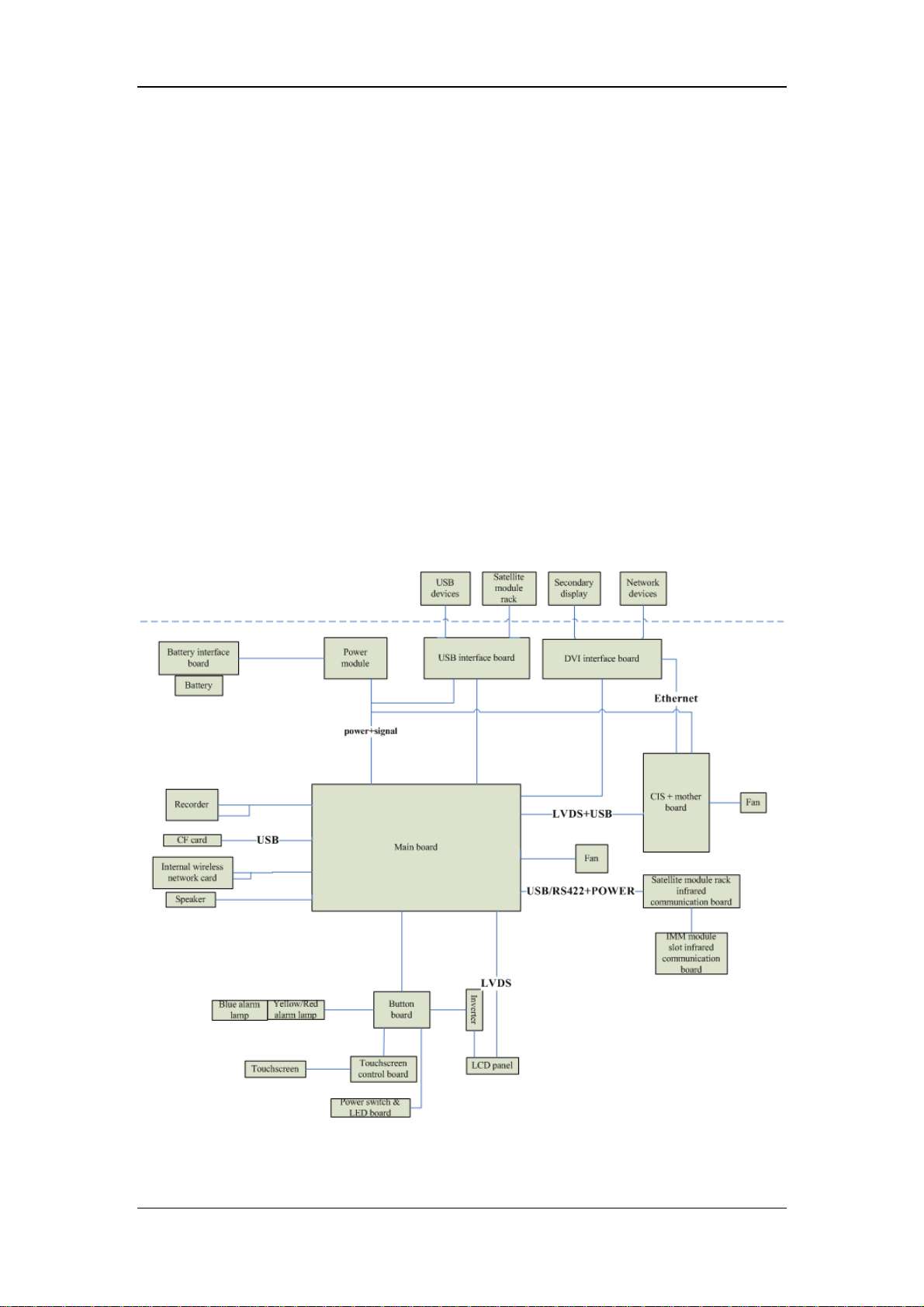
2.3 Main Unit
The patient monitor consists of:
Input system: button board, knob, touchscreen, power switch and LED board
Output system: LCD panel, alarm LED board, recorder, speaker
Processing and communications system: main board, CIS assembly, integral module
rack
Power management system: battery, battery interface board, power module
Equipment interface system: USB interface board, DVI interface board, CF card
assembly and internal wireless network card.
Additionally, the patient monitor can also connect satellite module rack (SMR), parameter
modules, BeneLink module, mouse, keyboard, etc.
The following diagram illustrates the structure of the patient monitor.
2-4
Page 21
2.3.1 Input System
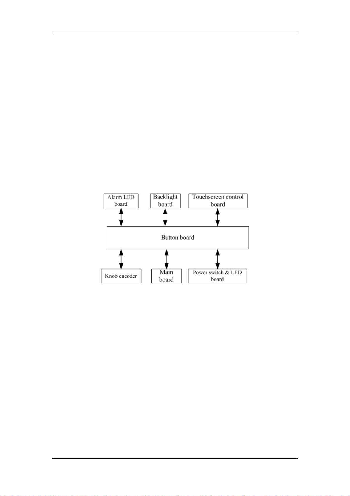
Button board
The button board, located at the lower part of the monitor’s front panel, contains 6 keys and
provides connections for the following components to the main board:
Knob
Power switch & LED board
Touchscreen control board
Backlight board
Alarm LED board
The following diagram shows the button board connections.
Knob
The knob can be pressed, or rotated both clockwise and counter-clockwise. It is connected
with the button board.
Touchscreen
The touchscreen enables touch operations and can be calibrated. It is connected with the
touchscreen control board and main board.
Power switch & LED Board
The power switch & LED board controls the power supply for the main unit. It has three
LEDs, which respectively indicate the AC power status, battery status and monitor power
on/off status. It is connected with the button board.
2-5
Page 22
2.3.2 Output System
LCD
The patient monitor adopts a high-resolution LCD. The LCD is connected with the main
board. Signals and power supply of the backlight board are transferred by the button board.
Alarm Lamp
The patient monitor has two alarm lamps: alarm lamp and technical alarm lamp. Alarm lamp
lights either red or yellow whereas technical alarm lamp lights blue only. The signals from
the alarm lamps are transferred by the button board and are controlled directly by the main
board.
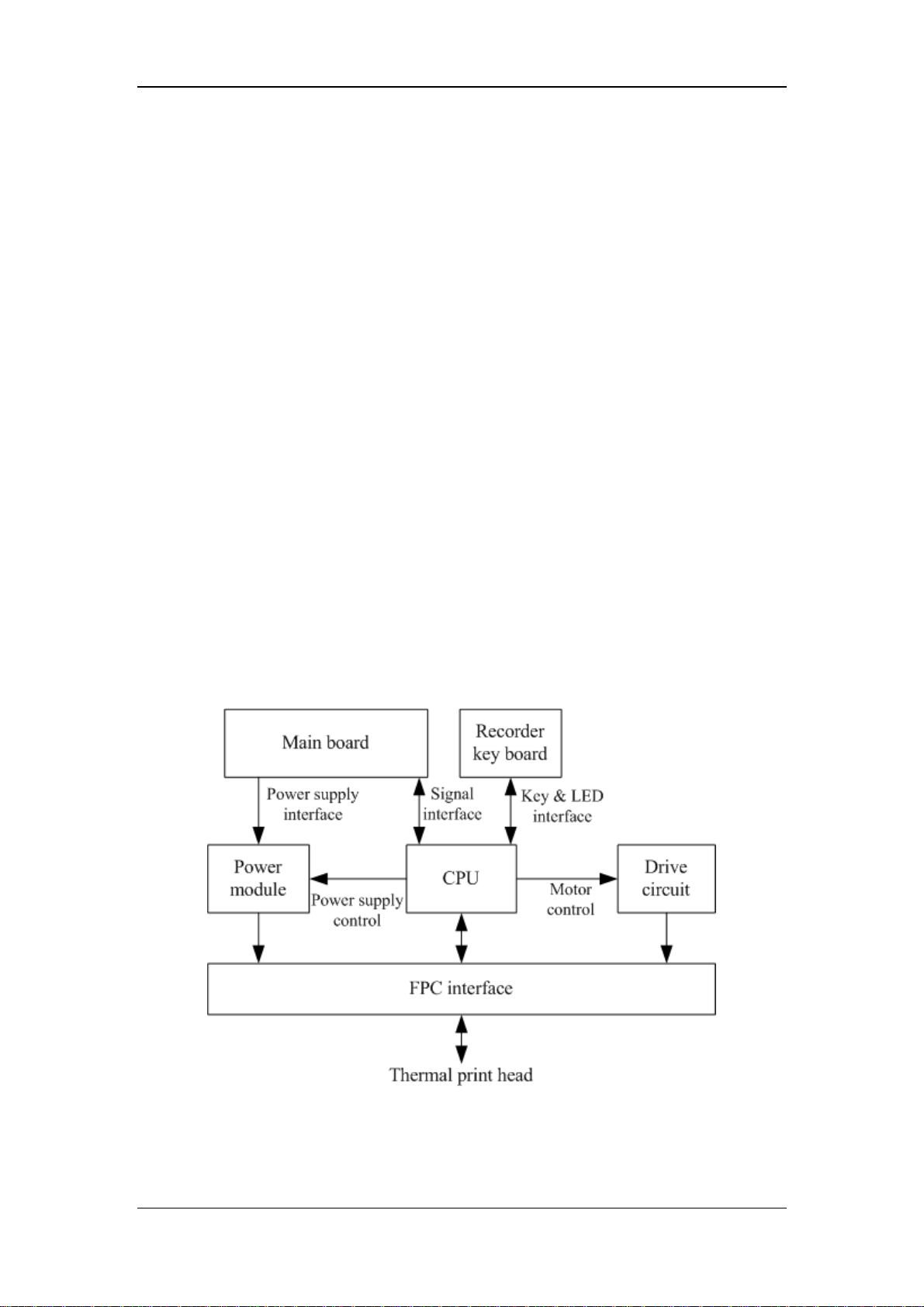
Recorder
The recorder receives data coming form the main board and then sends them to the thermal
printhead for printing. The recorder has a hardkey (starting/stopping recordings) and a green
LED on its front. It is connected with the main board.
The following diagram shows its operating principle.
2-6
Page 23

Module Description
Power interface Introduces a DC from the main board.
Power module
CPU Control the communications between modules.
Signal interface
Motor drive circuit
Button & LED
board
Converts the input power into voltages that fit each module and then
forwards them to each module.
Control the communications between the main board and the
recorder CPU.
Receives the control signals from the CPU and then forwards them to
the step engines.
Includes one button and one LED which are directly controlled by
the CPU.
Speaker
The speaker provides sound for alarms, key strokes, heart beats and pulse, and allows PITCH
TONE and multi-level tone modulation. It is connected with the main board and is directly
driven by the main board.
2.3.3 Processing and Communications System
Main Board
The main board is the heart of the patient monitor. It implements a series of tasks including
input & output control, data storage and processing, display processing, system control,
communication management, printing management and alarming, etc.
The main board comprises the CPU board and mother board. The following diagram shows
interfaces to other components.
2-7
Page 24
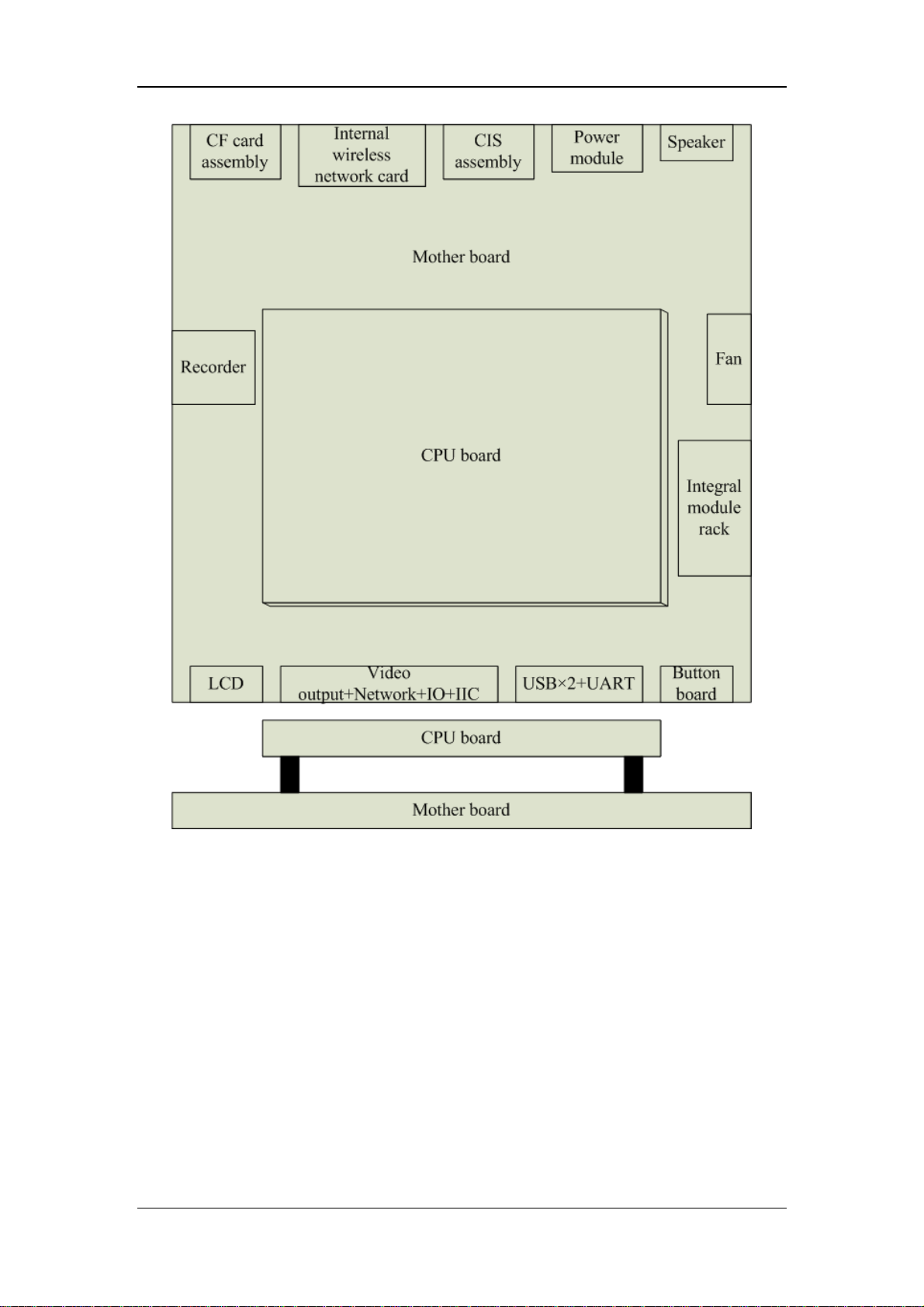
The CPU board is an essential CPU system containing the CPU, FLASH, memory, realtime
clock, EEPROM, etc. It interfaces to the mother board only, which then provides interfaces to
all other external devices.
The mother board is in charge of connections and communications with other components
and provides the following interfaces:
LCD port: connects a built-in display.
Video output+network+IO+IIC: connects the digital video interface board.
USB×2+UART: connects the USB interface board.
Button board port: connects the button board.
Integral module rack port: connects integral module rack communication board.
Fan port: connects the fan.
2-8
Page 25

Speaker port: connects the speaker.
Power module port: connects the power module.
CIS port: located at the back of the mother board for connecting the CIS components.
CF port: connects the CF card assembly.
Recorder port: connects the recorder.
Internal wireless network card port: connects the internal wireless network card
Integral Module Rack
The patient monitor has two kinds of integral module rack: 2-slot and 5-slot. The control
board includes a NIOS II FPGA. It implements protocol conversion and infrared
communication between the main unit and the parameter modules.
The module rack communication board can be a 2-slot type or a 3-slot type. The 3-slot
communication board communicates the main board directly. The 2-slot communication
board is connected with and is controlled by the 3-slot communication board. The 3-slot
communication board has the function of communication control. The 2-slot communication
board consists of the infrared circuit and module power circuit. The RS422 drive circuit is
located on the 3-slot communication board.
2.3.4 Power Management System
Battery
The patient monitor uses two chargeable lithium-ion batteries (11.1 V, 4500 mAh). The
battery compartment door is located at the bottom of the patient monitor. The battery power
is introduced to the power module via the battery interface board, and then processed and
distributed to each component by the power module.
NOTE
z Two batteries must be used simultaneously when the patient monitor operates on
battery power. Otherwise, it may cause power supply protection.
Battery Interface Board
The battery interface board connects batteries to the power module, enabling charging and
discharging between the batteries and the power board.
2-9
Page 26
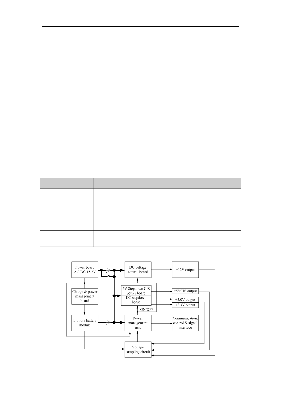
Power Module
The power module is located at the back of the patient monitor. The main part of the power
module is the power board, which contains 4 PCBs: charging & power management board,
voltage drop DC inverter, voltage rise and drop DC inverter, and voltage drop 5 V CIS power
board.
The power module transforms the input power into DC and then forwards them to each
component of the patient monitor. The input power comes from either the batteries or an AC
source. The patient monitor will run power from the AC source whenever an AC source is
available. If the AC source becomes unavailable, the patient monitor will automatically
switch to the battery power. This does not affect the monitor’s operating status.
Power module has an AC input socket at its backside, and a socket at its front provides 4
connections to the batteries, main board, CIS components and USB interface board
respectively. The power module protects itself and the patient monitor by switching off AC
input or DC output in case of overcurrent, short circuit and overvoltage.The power module
provides 4 DC outputs:
Outputs Description
+3.3 V
+5.0 V
+5.0 V CIS Goes to the CIS assembly.
+12 V
The systematic principle diagram of the power module is as follows:
Goes to the LCD, mother board, CPU board, DVI interface board and
integral module rack.
Goes to the DVI interface board, recorder, CF storage card board and
USB interface board.
Goes to the recorder, LCD inverter, integral module rack, parameter
modules and USB interface board.
2-10
Page 27

The following diagram shows the pins of the power module socket (excluding the pins of the
battery power socket. On power board, pin 1 has a triangle symbol):
Pin ID Marking Description Cable
color
2, 4, 6, 7,
13, 15, 17
8 RXD Receives serial communications (the main board sends). Purple
9 TXD Sends serial communications (the main board receives). Brown
10 PCON
11 LCD-EN
12, 1 12 V
14, 3 5 V CIS
GND The output grounding terminal of the power board. Black
Power on/off control signal. It is a TTL pulse signal
inputted from the back board. Every time when the power
on/off switch is pressed (pulse of falling edge), a switch
between power “on” and “off” happens. The pulse
duration is no less than 0.1 s for power-on and no less
than 2 s for power off.
Backlight on/off control signal. The main board sends a
backlight on/off control signal to the power board through
the serial interface. The power board processes the
received signal and then outputs a high or low level
depending on the received signal.
The positive end of the 12 V DC coming from the power
board.
The positive end of the 5 V CIS coming from the power
board.
Blue
Green
Yellow
Purple
16, 5 5 V
18, 19 3.3 V
20 LED- AC AC power status indication signal White
21 LED- BAT Battery status indication signal. Grey
22 LCD-BR Backlight brightness control voltage. Brown
The positive end of the 5 V DC coming from the power
board.
The positive end of the 3.3 V DC coming from the power
board.
2-11
Red
Orange
Page 28
2.3.5 Equipment Interface System
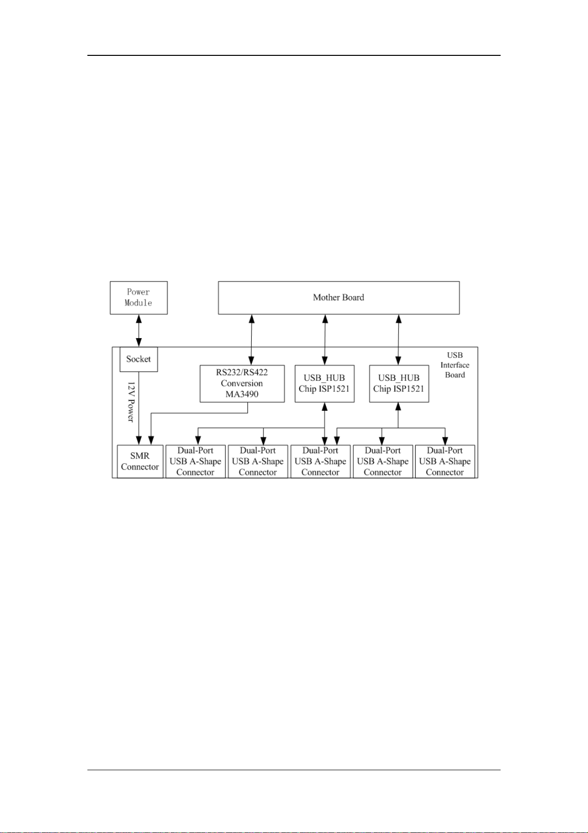
USB Interface Board
The USB interface board is compatible with such USB interfaces as USB2.0, USB1.1 and
USB1.0. It is connected with the main board and the power module. It receives two USB
differential signals coming from the main board and then distributes them to ten USB
interfaces via two ISP1521 chips. The UART signal output by the main board is converted
into RS422 signal by the USB interface board. The USB interface board receives 5 VDC and
12 VDC inputs from the power module, of which the 5 VDC goes to the USB interface board
and the 12 VDC outputted to the SMR connector through a fuse.
2-12
Page 29
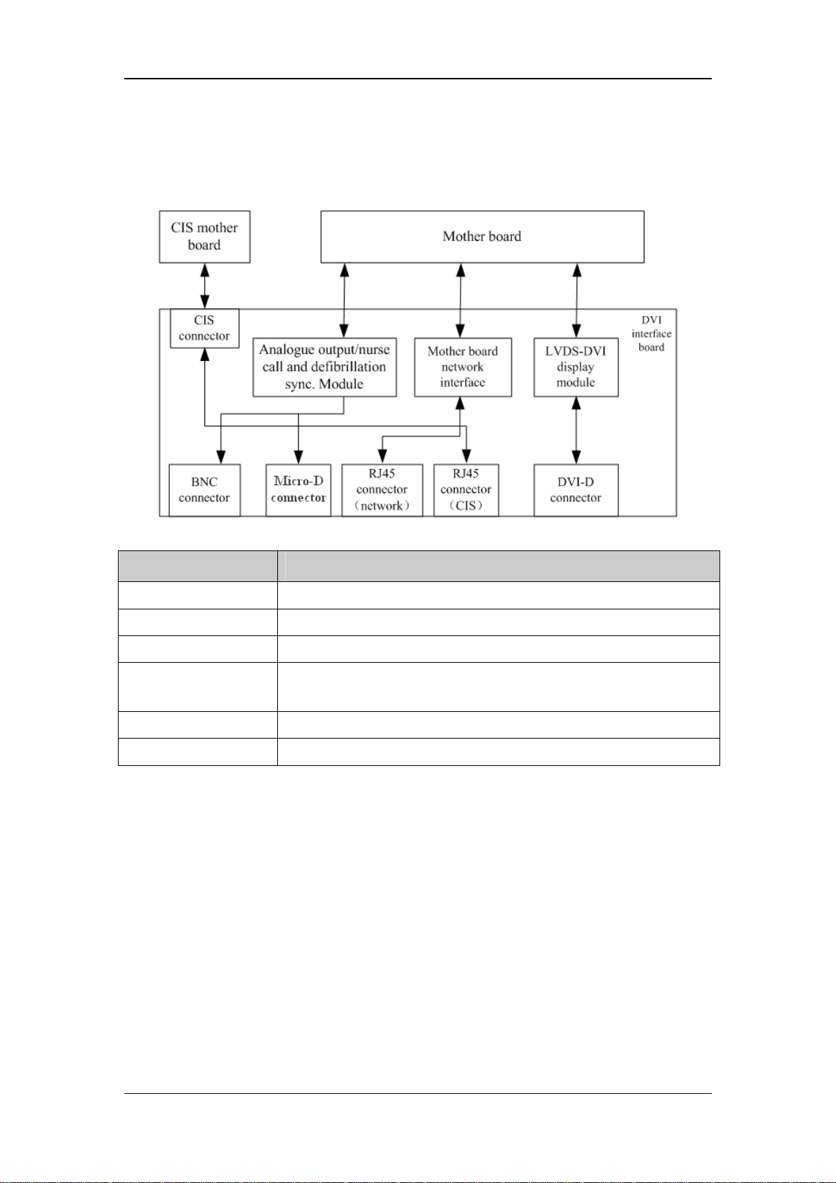
DVI Interface Board
The DVI interface board is connected with the mother board and the CIS mother board. The
following diagram shows its interfaces to other components.
Interface Description
CIS Connector Connects the CIS mother board.
BNC connector Outputs nurse call signals.
Micro-D connector Outputs analog signals and defibrillator synchronization signals.
RJ 45 connector
(network)
RJ 45 connector (CIS) It is a standard RJ45 connector for connecting a CIS network.
DVI-D connector Connects a secondary display.
It is a standard RJ45 connector, providing 10/100 BASE-TX Ethernet
communications channels. It connects an Ethernet network or a PC.
CF Card assembly
The CF assembly serves the non-volatile CF storage card which is used for data storage and
transfer. It is connected with the mother board.
Internal wireless network card
The internal wireless network card connects with the mother board. User can set network
type as LAN or WLAN through user interface and can set the internal wireless network card
through PC.
2-13
Page 30

2.4 Parameter Module
Each parameter module consists of the module infrared communication board, module power
board, module button board, parameter board, etc.
2.4.1 Module Infrared Communication Board
The module infrared communication board allows a short delay when powering up the
module and adopts FPGA to enable infrared communications between the module and the
module rack. An ID is integrated into the module infrared communication board. When a
module is inserted in the module rack, the ID is automatically sent to the module rack.
2.4.2 Module Power Board
Some modules have no power board. There are two kinds of module power board:
1. Isolated power board: converts the 12 V DC into a 12 V isolated DC and a 5 V isolated
DC.
2. Non-isolated power board: converts the 12 V DC into a 5 V DC.
2.4.3 Parameter Board
The parameter board is a parameter measurement component, which is the most important
component of the parameter module.
2-14
Page 31

2.5 Satellite Module Rack
The satellite module rack (SMR) is independent of the patient monitor, provides 8 slots for
mounting parameter modules. It has the following features:
It allows a parameter module to be plugged and unplugged with the patient monitor on.
This allows function extension and patient transfer.
It does not have its own power. It introduces 12 V DC from the patient monitor and then
supplies power to each parameter module via the contact screw.
It accomplishes communications protocol conversions between the patient monitor and
each parameter module, provides infrared communications for parameter modules, and
is responsible for detecting infrared communications malfunction for each parameter
module.
The following diagram shows the structure of the SMR.
2-15
Page 32

2.6 BeneLink Module
BeneLink module allows the information (patient data, alarms, etc.) from the external device
to be displayed, saved, recorded, printed, or calculated through a BeneView patient monitor.
If the patient monitor is connected with the CMS or gateway, information from the external
device can also be transmitted to the CMS or gateway. BeneLink module connects with the
external device through an ID module, which enables the information transmission between
the BeneLink module and the external device. BeneLink module can be connected to many
external devices such as anesthesia machine and ventilator.
The following diagram shows the structure of the BeneLink module:
BeneLink module interface
board for debugging
BeneView
patient monitor
External device
Infrared ray
232 Serial port
Infrared
commun
-ication
board
Isolation
circuit
I2S
BeneLink module interface board
Serial port ID interface board
Serial port of external
device
Connector
MCU
Debugging
AM1808
module
CPU
MCU serial
port
serial port
Multiplex switch
VCC
Serial port
ID_READ
ID_STATUS
Up serial port
ID_READ
ID_STATUS
Connector 4
Connector 1
232 Serial port
Connector
2-16
Page 33

3 Testing and Maintenance
3.1 Introduction
To ensure the patient monitor always functions normally, qualified service personnel should
perform regular inspection, maintenance and test. This chapter provides a checklist of the
testing procedures for the patient monitor with recommended test equipment and frequency.
The service personnel should perform the testing and maintenance procedures as required and
use appropriate test equipment.
The testing procedures provided in this chapter are intended to verify that the patient monitor
meets the performance specifications. If the patient monitor or a module fails to perform as
specified in any test, repairs or replacement must be done to correct the problem. If the
problem persists, contact our Customer Service Department.
CAUTION
z All tests should be performed by qualified service personnel only.
z Care should be taken to change the settings in [User Maintenance] and [Factory
Maintenance] menus to avoid loss of data.
z Service personnel should acquaint themselves with the test tools and make sure
that test tools and cables are applicable.
3.1.1 Test Equipment
See the following sections.
3-1
Page 34

3.1.2 Test Report
Upon completion of the tests, the table of preventative maintenance test reports and the table
of maintenance test reports in this chapter should be kept properly.
3.1.3 Preventative Maintenance
Below are preventative maintenance tests which need to be performed on the monitor. See the
following sections for detailed maintenance procedures.
Visual inspection
NIBP test and calibration
Microsteam and Sidestram CO
test and calibration
2
AG test and calibration
3.1.4 Recommended Frequency
Check/Maintenance Item Frequency
Preventative Maintenance Tests
Visual inspection 1. When first installed or reinstalled.
NIBP test
Sidestream and
Microstream
tests
CO
2
AG tests
Pressure check
Leakage test
Calibration
Leakage test
Performance test
Calibration
Leakage test
Performance test
Calibration
1. If the user suspects that the measurement is
incorrect.
2. Following any repairs or replacement of
relevant module.
3.At least once a year is recommended for NIBP,
and AG.
CO
2
Performance Tests
Performance test ECG test
Calibration
Resp performance test
1. If the user suspects that the measurement is
incorrect.
2. Following any repairs or replacement of
relevant module.
3-2
Page 35

SpO2 test
Pressure check
3. At least once every two years.
Note: At least once a year is recommended for
NIBP, CO
and AG.
2
NIBP test
Leakage test
Calibration
Temp test
Performance test
IBP test
Pressure calibration
C.O. test
Mainstream CO2 test
Leakage test
Sidestream and
Microstream
tests
CO
2
Performance test
Calibration
Leakage test
AG tests
Performance test
Calibration
ICG test
BIS test
RM test
Interconnecting
CCO/SvO2 test
function
Output calibration
PiCCO test
ScvO2 test
Nurse call relay performance test
Analog output performance test
Electrical Safety Tests
Electrical
safety tests
Refer to A Electrical
Safety Inspection.
If the user suspects that the nurse call or analog
output does not work well.
1. Following any repair or replacement
2. After the monitor drops.
3. At least once every two years.
3-3
Page 36

Other Tests
Power on test
Touchscreen calibration
Recorder check
Network print test
Device integration check
1. When first installed or reinstalled.
2. Following any maintenance or the
replacement of any main unit parts.
1. When the touchscreen appears abnormal.
2. After the touchscreen is replaced.
Following any repair or replacement of the
recorder.
1. When first installed.
2. Whenever the printer is serviced or replaced.
1. When first installed.
2. Following any repair or replacement of the
external device.
Battery check
Functionality
test
1. When first installed.
2. Whenever a battery is replaced.
3.2 Preventative Maintenance Procedures
3.2.1 Visual Inspection
Inspect the equipment for obvious signs of damage. The test is passed if the equipment has no
obvious signs of damage. Follow these guidelines when inspecting the equipment:
Carefully inspect the case, display screen, buttons and knob for obvious signs of
damage.
Inspect the SMR and parameter modules for obvious signs of damage.
Inspect the power cord, wall-mount bracket and module accessories for obvious signs of
damage
Inspect all external connections for loose connectors, bent pins or frayed cables.
Inspect all connectors on the equipment for loose connectors or bent pins.
Make sure that safety labels and data plates on the equipment are clearly legible.
3-4
Page 37

r
3.2.2 NIBP Tests
NIBP Accuracy Test
Tools required:
T-shape connector
Appropriate tubing
Balloon pump
Rigid Vessel with volume 500 ± 25 ml
Reference manometer (calibrated with accuracy equal to or greater than 1 mmHg)
Follow this procedure to perform the test:
1. Connect the equipment as shown below.
Monito
Connector for NIBP cuff
Balloon pump
2. Before inflation, the reading of the manometer should be 0. If not, turn off the balloon
pump to let the whole airway open to the atmosphere. Turn on the balloon pump after
the reading is 0.
3. Select [Main Menu]→ [Maintenance >>]→ [NIBP Accuracy Test].
4. Check the manometer values and the monitor values. Both should be 0mmHg.
5. Raise the pressure in the rigid vessel to 50 mmHg with the balloon pump. Then, wait for
10 seconds until the measured values become stable.
Tubing
Manometer
Rigid vessel
6. Compare the manometer values with the monitor values. The difference should be 3
mmHg. If it is greater than 3 mmHg, calibrate the monitor by referring to the NIBP
Calibration section.
7. Raise the pressure in the rigid vessel to 200 mmHg with the balloon pump. Then, wait
for 10 seconds until the measured values become stable and repeat step 6.
3-5
Page 38

NOTE
z You can use an NIBP simulator to replace the balloon pump and the reference
manometer to perform the test.
z You can use an appropriate cylinder and a cuff instead of the rigid vessel.
NIBP Leakage Test
NOTE
z You should perform NIBP accuracy test and make sure the test result is pass prior
to NIBP leakage test.
Tools required:
NIBP cuff for adult patient
Appropriate tubing
Cylinder
Follow this procedure to perform the test:
1. Set [Patient Cat.] to [Adu].
2. Connect the NIBP cuff with the NIBP connector on the monitor.
3. Apply the cuff to the cylinder as shown below.
Monitor
Connector for
NIBP cuff
4. Select [Main Menu]→ [Maintenance>>]→ [NIBP Leakage Test]. The message
[Leakage Testing…] is displayed in the NIBP parameter area.
Air tubing
Cylinder
Cuff
5. The cuff automatically deflates after 20s, which means NIBP leakage test is completed.
If no message is displayed in the NIBP parameter area, it indicates that the system has no
leakage. If the message [NIBP Pneumatic Leak] is displayed, it indicates that the system may
have a leakage. In this case, check if all connections are good and the cuff and tubing have no
leakage. Perform the test again after making sure all connections are good and the cuff and
tubing have no leakage.
3-6
Page 39

You can either perform a manual leakage test:
1. Perform procedures 1-4 in the NIBP Accuracy Test section.
2. Raise the pressure in the rigid vessel to 250 mmHg with the balloon pump. Then, wait
for 5 seconds to let the measured values becoming stable.
3. Record the current pressure value and meanwhile use a time counter to count time. Then,
record the pressure value after counting to 60s.
4. Compare the two values and make sure the difference should not be greater than 6
mmHg.
NIBP Calibration
Tools required:
T-shape connector
Approprating tubing
Balloon pump
Metal Vessel with volume 500 ± 25 ml
Reference manometer (calibrated with accuracy equal to or greater than 1 mmHg)
Follow this procedure to perform a NIBP calibration:
1. Perform procedures 1-4 in the NIBP Accuracy Test section.
2. Select [Main Menu]→ [Maintenance >>]→ [Factory Maintenance >>]→ enter the
required password→ [Calibrate NIBP >>].
3. Set [NIBP Pressure] to 150 mmHg in the [NIBP Measurement Circuit]. Raise the
pump pressure to 150 mmHg. After the pressure value is stabilized, select the
[Calibrate] button to start a calibration.
5. Set patient category to [Adu/Ped] in the [Overpressure Protection Circuit], and raise
the pressure to 330 mmHg. After the pressure value is stabilized, select [Calibrate] to
start a calibration.
6. Set the patient category to [Neo] in the [Overpressure Protection Circuit], and raise
the pressure to 165 mmHg. After the pressure value is stabilized, select [Calibrate] to
start a calibration.
All calibration results are displayed in the [Calibrate NIBP] menu. If the calibration fails,
check the test system for leakage and perform another calibration.
3-7
Page 40

3.2.3 Sidestream and Microstream CO2 Module Tests
Leakage test
Follow this procedure to perform the test:
1. Plug the module into the module rack.
2. Wait until CO
warmup is finished and then use your hand or other objects to
2
completely block the gas inlet of the module or watertrap. The sidestream and
microstream CO
Sidestream: The alarm message [CO
modules will behave as follows:
2
after certain time. Block the gas inlet for another 30 s. If the alarm message does
not disappear, it indicates that the module does not leak.
Microstream: The alarm message [CO
certain time. Block the gas inlet for another 30s. If alarm message [CO
Err] is shown, it indicates that the module does not leak.
Accuracy Test
Tools required:
A steel gas cylinder with 6±0.05% CO
T-shape connector
Tubing
FilterLine Err] is displayed on the screen
2
Purging] is displayed on the screen after
2
FilterLine
2
and balance gas N2
2
Follow this procedure to perform the test:
1. Plug the module into the module rack.
2. Wait until the CO
module warmup is finished, and check the airway for leakage and
2
perform a leakage test as well to make sure the airway has no leakage.
3. Enter [User Maintenance]→ [Maintain CO
4. Connect the test system as follows:
Open to the air
Tubing
Relief valve
Gas cylinder
Purging]→ [Calibrate CO2>>].
2
Monitor
3-8
Page 41

5. Open the relief valve to vent standard CO2 and make sure that there is an excess gas
flow through the T-shape connector to air..
6. Check the realtime CO
value is within 6±0.05% in the [Calibrate CO
2
] menu.
2
Calibration
Tools required:
A steel gas cylinder with 6±0.05% CO
T-shape connector
Tubing
Follow this procedure to perform a calibration:
1. Make sure that the sidestream or microstream CO
started up.
2. Check the airway for leakage and perform a leakage test as well to make sure the airway
has no leakage.
3. Select [Main Menu]→ [Maintenance >>]→ [User Maintenance >>]→ enter the
required password→ [Maintain CO
4. In the [Calibrate CO
] menu, select [Zero].
2
and balance gas N2
2
module has been warmed up or
2
>>]→ [Calibrate CO2 >>].
2
5. After the zero calibration is finished successfully, connect the equipment as follows:
Open to the air
Tubing
Relief valve
Monitor
Gas cylinder
6. Open the relief valve to vent standard CO
and make sure that there is an excess gas
2
flow through the T-shape connector to air.
7. In the [Calibrate CO
8. In the [Calibrate CO
measured CO
concentration becomes stable, select [Calibrate CO
2
] menu, enter the vented CO
2
] menu, the measured CO2 concentration is displayed. After the
2
concentration in the [CO
2
] to calibrate the
2
2
CO2 module.
] field.
If the calibration is finished successfully, the message [Calibration Completed!] is
displayed in the [Calibrate CO
] menu. If the calibration failed, the message [Calibration
2
Failed!] is displayed. In this case, perform another calibration.
3-9
Page 42

3.2.4 AG Tests
Leakage Test
Follow this procedure to perform the test:
1. Plug the AG module into the module rack.
2. Wait until the AG module warmup is finished and then use your hand or other objects to
completely block the gas inlet of the AG module. An alarm message [AC Airway
Occluded] will appear on the screen.
3. Block the gas inlet for another 30 s. If the alarm message does not disappear, it indicates
that the module does not leak.
Accuracy Test
Tools required:
Gas cylinder with 100% O
and a certain standard gas (such as 6±0.05% CO2,Bal N2),
2
or standaerd gas mixture. Gas concentration should meet the following requirements :
AA≥1.5%, CO
≥1.5%, N2O≥40%, O2≥40%, of which AA represents an anesthetic
2
agent. a/c≤0.01 (a is the gas absolute concentration accuracy; c is the gas
concentration)
T-shape connector
Tubing
Follow this procedure to perform the test:
1. Plug the AG module into the module rack.
2. Wait at least 10 min and then perform a leakage test to make sure the airway has no
leakage.
3. Check if the fan inside the AG module works correctly.
4. Connect the test system as follows:
Open to the air
Relief valve
Gas cylinder
Tubing
Monitor
3-10
Page 43

5. Open the relief valve and vent a standard gas and make sure that there is an excess gas
flow through the T-shape connector to air.
6. Check that the concentration of each composition meets the specification stated in the
Operator's Manual.
WARNING
z When performing AG accuracy test and AG calibration, be sure to dispose of
exhaust gas properly.
Calibration
Tools required:
Gas cylinder, with a certain standard gas or mixture gas. Gas concentration should meet
the following requirements: AA≥1.5%, CO
AA represents an anesthetic agent. a/c≤0.01 (a is the gas absolute concentration
accuracy; c is the gas concentration).For 100% O
is used and the O2 concentration is not less than 99%.
O
2
≥1.5%, N2O≥40%, O2≥40%, of which
2
calibration, a gas cylinder with 100%
2
T-shape connector
Tubing
Follow this procedure to perform a calibration:
1. Select [Main Menu]→ [Maintenance >>]→ [User Maintenance >>]→ enter the
required password→ [Calibrate AG >>].
2. Check the airway and make sure that there are no occlusions or leaks.
Vent the sampling tubing to the air and check if the [Current FlowRate] and [Set
FlowRate] are approximately the same. If the deviation is great, it indicates that
there is an occlusion in the tubing. Check the tubing for an occlusion.
Perform a leakage test to make sure that the airway has no leakage.
3-11
Page 44

Connect the test system as follows:
Open to the air
Tubing
Relief valve
Monitor
Gas cylinder
4. Open the relief valve and vent a certain standard gas or gas mixture and make sure that
there is an excess gas flow through the T-shape connector to air.
5. In the [Calibrate AG] menu, the concentration and flowrate of each measured gas are
displayed.
If the difference between the measured gas concentration and the actual one is
tolerable, a calibration is not needed.
If the difference is great, a calibration should be performed. Select [Calibrate >>]
to enter the calibrate menu.
6. Enter the vented gas concentration. If you use only one gas for calibration, set other
gases’ concentration to 0.
7. Select [Start] to start a calibration.
8. If the calibration is finished successfully, the message [Calibration Completed!] is
displayed. If the calibration failed, the message [Calibration Failed!] is displayed.
Perform another calibration.
3-12
Page 45

CAUTION
z Calibrate the O
suspect it does not work properly.
module, If it has been transported for long distance or if you
2
3.2.5 Preventative maintenance test report
Customer name
Customer address
Servicing person
Servicing company
Equipment under test
(EUT)
Model of EUT
SN of EUT
Hardware version
Software version
Test equipment Model/No. Effective date of calibration
Test items Test records Test
results(Pass/Fail)
Visual inspection
The case, display screen, buttons, knob, SMR, modules, power
cord, wall-mount bracket and accessories have no obvious
signs of damage.
The external connecting cables are not frayed and the
connector pins are not loose and bent.
The external connectors are not loose or their pins are not
bent.
The safety labels and data plate are clearly legible.
NIBP test
3-13
Page 46

The difference is within ±3 mm when 0, 50 or 200 mmHg is
set for NIBP accuracy test.
There is no leakage with NIBP, or the manual leakage test
result does not exceed 6mmHg/min.
Sidestream CO2 test
Block the gas inlet of the module or watertrap. The sidestream
flowrate is slower than 10ml/min and an alarm of CO2
CO
2
Filterline Err is given. It indicates that there is no leakage.
The displayed CO2 value is within 6±0.05%.
Microstream CO2 test
Block the gas inlet of the module or watertrap. An alarm of
Filterline Err is given. It indicates that there is no leakage.
CO
2
The displayed CO2 value is within 6±0.05%.
AG test
When AG flowrate is slower than 10ml/min, an alarm of AG
Airway Occluded is given. It indicates that there is no leakage.
The fan inside the AG module works properly.
The measurement accuracy of CO2, N2O, O2 and AA (AA
represents an anaesthetic agent) meets the product
specifications in the Operator’s Manual.
3.3 Power On Test
This test is to verify that the patient monitor can power up correctly. The test is passed if the
patient monitor starts up by following this procedure:
1. Insert two batteries in the battery chamber and connect the patient monitor to the AC
mains, the AC mains LED and battery LED light.
2. Press the power on/off switch to switch on the patient monitor. The operating status
LED lights up, and the technical and physiological alarm lamps light blue and red
respectively.
3. After the start-up screens are displayed, the system sounds a beep indicating the self test
on alarm sounds is passed. At the same time, the alarm lamp turns from yellow to red,
and then turns off together with the technical alarm lamp. This indicates that the self test
on alarm lamps is passed.
4. The patient monitor enters the main screen and start-up is finished.
3-14
Page 47

3.4 Module Performance Tests
3.4.1 ECG Tests
ECG Performance Test
Tool required:
Fluke Medsim 300B patient simulator recommended
Follow this procedure to perform the test:
1. Connect the patient simulator with the ECG module using an ECG cable.
2. Set the patient simulator as follows: ECG sinus rhythm, HR=80 bpm with the amplitude
as 1mV.
3. Check the ECG waves are displayed correctly without noise and the displayed HR value
is within 80 ± 1 bpm.
4. Disconnect each of the leads in turn and observe the corresponding lead off message
displayed on the screen.
5. Set that the simulator outputs paced signals and set [Paced] to [Yes] on the monitor.
Check the pace pulse marks on the monitor screen.
ECG Calibration
Tool required:
Vernier caliper
Follow this procedure to perform a calibration:
1. Select the ECG parameter window or waveform area→ [Filter]→ [Diagnostic].
2. Select [Main Menu]→ [Maintenance>>].
3. Select [Calibrate ECG]. A square wave appears on the screen and the message [ECG
Calibrating] is displayed.
4. Compare the amplitude of the square wave with the wave scale. The difference should
be within 5%.
5. After completing the calibration, select [Stop Calibrating ECG].
If necessary, you can print out the square wave and wave scale through the recorder and then
measure the difference.
3-15
Page 48

3.4.2 Resp Performance Test
Tool required:
Fluke Medsim 300B patient simulator recommended
Follow this procedure to perform the test:
1. Connect the patient simulator to the module using a non ESU-proof cable and set lead II
as the respiration lead.
2. Configure the simulator as follows: lead II as the respiration lead, base impedance line
as 1500 Ω; delta impedance as 0.5 Ω, respiration rate as 40 rpm.
3. Check the Resp wave is displayed without any distortion and the displayed Resp value is
within 40 ± 2 rpm.
3.4.3 SpO2 Test
Tool Required:
None.
Follow this procedure to perform the test:
1. Connect SpO2 sensor to the SpO
and [PR Source] to SpO
2. Measure SpO
on your finger. (Assume that you stay healthy)
2
on the monitor.
2
connector of the monitor. Set [Patient Cat.] to [Adu]
2
3. Check the Pleth wave and PR reading on the screen and make sure that the displayed
is within 95%-100%.
SpO
2
3. Remove the SpO
sensor from your finger and make sure that an alarm of SpO2 Sensor
2
Off is triggered.
NOTE
z A functional tester cannot be used to assess the accuracy of a pulse oximeter
monitor. However, it can be used to demonstrate that a particular pulse oximeter
monitor reproduces a calibration curve that has been independently demonstrated
to fulfill a particular accuracy specification.
3-16
Page 49

3.4.4 NIBP Tests
See section 3.2.2 NIBP Tests.
3.4.5 Temp Test
Tool required:
Resistance box (with accuracy above 0.1Ω)
Follow this procedure to perform the test:
1. Connect the two pins of any Temp connector of a module to the two ends of the
resistance box using 2 wires.
2. Set the resistance box to 1354.9Ω (corresponding temperature is 37ºC).
3. Verify each Temp channel of the monitor and make sure that the displayed value is
within 37 ± 0.1ºC.
You can also use a patient simulator to perform the Temp test.
3.4.6 IBP Tests
IBP Performance Test
Tool required:
Medsim300B patient simulator, MPS450, or other equivalent device
Dedicated IBP adapter cable (300B, P/N 00-002199-00) (use P/N 00-002198-00, if the
simulator is MPS450)
Follow this procedure to perform the test:
1. Connect the patient simulator with the pressure module.
2. Make the patient simulator outputs 0 to each IBP channel.
3. Press the Zero Key on the module to make a zero calibration.
4. Configure the patient simulator as P (static) = 200 mmHg.
5. The displayed value should be within 200 ± 2 mmHg.
6. If the value is outside of these tolerances, calibrate the pressure module. If the IBP
module was calibrated with a dedicated reusable IBP sensor, check the calibration
together with this IBP sensor.
7. Make that the patient simulator outputs 120/80 mmHg ART signals and 120/0 mmHg
LV signals respectively to each IBP channel and check that the IBP wave is displayed
correctly.
8 Repeat the steps above for all the IBP channels.
3-17
Page 50

IBP Pressure Calibration
Method 1:
Tools required:
Medsim300B Patient simulator, MPS450, or other equivalent device
Dedicated IBP adapter cable (300B, P/N 00-002199-00) (use P/N 00-002198-00, if the
simulator is MPS450)
Follow this procedure to perform the test:
1. Connect the patient simulator to the pressure connector on the module.
2. Set the patient simulator to 0 pressure for the desired IBP channel.
3. Press the Zero Key on the module to make a zero calibration.
4. Configure the patient simulator as P (static) = 200 mmHg.
5. Select [Main Menu]→ [Maintenance >>]→[User Maintenance >>] →[Cal. IBP
Press. >>]. In the [Cal. IBP Press.] menu, set the calibration value to 200 mmHg.
6. Select the [Calibrate] button next to the desired IBP channel to start a calibration.
7. If the calibration is completed successfully, the message [Calibration Completed!] will
be displayed. Otherwise, a corresponding message will be displayed.
Method 2:
Tools required:
Standard sphygmomanometer
Balloon pump
Tubing
T-shape connector
To perform a calibration:
1. Connect the 3-way stopcock, the sphygmomanometer and the balloon pump through a
T-shape connector, as shown below.
2. Zero the transducer. Then open the stopcock to the sphygmomanometer.
3. Press the Main menu button on the equipment’s front panel. Select [Maintenance>>]→
[User Maintenance >>]→ enter the required password→[Cal. IBP Press. >>]. Then
configure IBP calibration value.
4. Inflate using the balloon pump until the reading of sphygmomanometer approximates
the preset calibration value.
3-18
Page 51

k
Pressure transducer
3-way stopcoc
T-shape connector
Sphygmomanometer
5. Adjust the calibration value in the [Cal. IBP Press.] menu until it is equal to the reading
of sphygmomanometer
6. Select the [Calibrate] button to start a calibration
7. The message [Calibration Completed!] is displayed after a successful calibration. If
the calibration failed, the prompt [Calibration Failed!] will be displayed.
Pressure adapter cable
IBP Module
3.4.7 C.O. Test
Tools required:
Medsim300B Patient simulator
C.O. adapter box
Follow this procedure to perform the test:
1. Connect the patient simulator to the C.O. module using a C.O. main cable.
2. Set the blood temperature (BT) to 37ºC on the patient simulator and check the
temperature value is 37 ± 0.1ºC.
3. Set [Auto IT] to [Off] and adjust [IT] to 24ºC. Select [C.O. Measure] to enter the C.O.
measurement window and set [Comp. Const.] to 0.595.
4. Set the injectate temperature to 24ºC and the C.O. to 5L/min on the C.O. simulator.
Select [Start] in the C.O. measurement window to start C.O. measurements and after
3-10 seconds press the run key on the simulator.
5. Check the C.O. value is 5±0.25L/min.
3-19
Page 52

3.4.8 Mainstream CO2 Tests
NOTE
z Make sure that the barometric pressure set in [Maintain CO
] of [User
2
Maintenance] accords with the local barometric pressure before performing
mainstream CO
tests.
2
Tools required:
A steel gas cylinder with 6±0.05% CO
A steel gas cylinder with compressed air or N
2
(with standard concentration)
2
Two 3-way valves (power supply controlled)
Flowmeter
Power supply
Tube
Follow this procedure to perform the test:
1. Wait until CO
warmup is finished and then select [Start Zero Cal.]from [CO2 Setup]
2
menu to start a zero calibration. If the zero calibration fails, the prompt message [CO
Zero Failed] is displayed. Otherwise, the baseline of waveform recovers to zero.
2
2 Set [Apnea Time] to 10 s in the [Adjust CO
3 Blow to the CO
Check if the alarm message [CO
sensor to generate a CO2 waveform and then place the sensor in the air.
2
Apnea] is displayed on the screen.
2
4 Connect the test system as follows
2 Limits] menu.
2
3-20
Page 53

Indication of numbers in the figure above
1 A steel gas cylinder with 6±0.05% CO
2
2 Flowmeter
3 3-way valve (power supply controlled)
4 Open to air
5 Power supply (controlling two 3-way valves)
6 Compressed air or N
7 Mainstream CO
with standard concentration
2
sensor
2
8 Patient monitor
9 Tube (preventing back flow)
5 Adjust the power supply and turn on/off 3-way valves to ensure that that only one
cylinder is connected to Mainstream CO
sensor via 3-way valves at one time and the
2
flowmeter reading is stable and within 2-5L/min.
6 Switch between the two cylinders to connect Mainstream CO
-10s and check if the displayed CO
value is within 6±0.05%.
2
sensor at intervals of 6
2
3.4.9 Sidestream and Microstream CO2 Module Tests
See section 3.2.3 Sidestream and Microstream CO2 Module Tests.
3.4.10 AG Tests
See section 3.2.4 AG Tests.
3-21
Page 54

3.4.11 ICG Test
Tool required:
ICG simulator (BZ-4575)
1. Connect the ICG simulator and the patient monitor using standard ICG cable and sensor.
2. Select [ICG setup]→ [Patient Demographics >>] and then input parameter values as
follows:
Height 180 cm CVP 6 mmHg
Weight 75 kg PAmean 8 mmHg
PAWP 10 mmHg
3. Switch on the simulator and set as follows: HR=60±1 bpm, VI=61±4/1000s,
TFC=32±2/kOhms. Then, start ICG monitoring.
4. After the measurement becomes stable and check that the measured results are as
follows: HR=60±2 bpm, VI=61±4/1000s, TFC=32±2/kOhms.
5. Set on the simulator as follows: HR=70±1 bpm, VI=48±4 /1000s, TFC=32±2 / kOhms,
and then start ICG monitoring. After the measurement becomes stable and check that the
measured results are as follows: HR=70±2 bpm, VI=48±4 /1000s, TFC=32±2 / kOhms.
3-22
Page 55

3.4.12 BIS Test
You can choose either of the following methods to perform the test:
Method 1:
Tools required:
None.
1. Connect the BIS sensor to a healthy, wide-awake adult as directed in the Operator’s
Manual.
2. Check the EEG wave and BIS numerics displayed on the screen and make sure the BIS
value is within 80-100.
Method 2:
Tools required:
BIS simulator (with flexible cable)
1. Connect the BIS sensor with the BIS simulator and select [BIS Setup]→ [BIS Sensor
Check] to perform a cyclic impedance check.
2. After the cyclic impedance check is finished, check that the result for each electrode is
pass.
3. Check the EEG wave and BIS numeric displayed on the screen.
3-23
Page 56

3.4.13 RM Test
Tool required:
Gas source
Ventilator (calibrated)
Artificial lung
Pediatric/neonate flow sensor
Monitor
Ventilator
Flow sensor
Follow this procedure to perform the test:
1. Connect the equipment as shown above. Make sure that the blue sensing tube on the
flow sensor is connected with the artificial lung.
2. Set [Patient Cat.] to [Adu]. In the [RM Setup] menu, select [Sensor Type] according
to the used sensor and set [Ventilation Mode] to [Mechanical].
3. Enter the [RM Setup] menu and select [Calibrate >>]. Input the constant marked on the
sensor and calibrate the flow sensor.
4. Configure the ventilator as follows: TV=500 ml, RR =20 rpm, I:E=1:2.
5. Select [Respiratory Loop] in the [RM Setup] menu. Verify that the displayed TV is
within 500±50ml and RR is within 20±1rpm.
Artificial lung
3-24
Page 57

3.4.14 CCO/SvO2 Tests
Interconnecting Function
Tools required:
None.
1. Connect and set the patient monitor and Vigilance monitor per the procedures in the
Operator’s Manual.
2. Set the Vigilance monitor to Demo mode.
3. Check that the CCO/SvO
numerics displayed on the patient monitor and Vigilance
2
monitor are consistent.
Output Performance
Tools required:
Oscillograph
1. Connect the signal output end of the connecting cables of the CCO/SvO
oscillograph.
2. Make the monitor to perform an ECG calibration. Check that the ECG waves displayed
on the oscillograph are consistent with the ECG calibration waves displayed on the
monitor screen.
3. Select [CCO Setup]→ [Signal Output Setup >>] and then select [Simulated High
Value] from the pop-up menu. Check that the amplitude of electrical level at the signal
output port of MAP, CVP and SpO
are 5±0.25V, 5±0.25V and 10±0.5V respectively.
2
module to the
2
3-25
Page 58

3.4.15 PiCCO Tests
You can perform PiCCO test by either of the following two methods:
Method 1:
Tools required:
Patient simulator: Medsim300B
Pulsion Calbox
PiCCO IBP test cable
1. Connect the PiCCO cable to the PiCCO module and the Pulsion Calbox respectively.
2. Connect the PiCCO IBP test cable to the PiCCO module and the patient simulator
respectively.
3. Adjust the knob on the Pulsion Calbox. Check that the detected catheter type accords
with the setup of the Pulsion Calbox, and the measurement errors of TB and TI are
within ±0.1℃.
Method 2:
Tools required:
Patient simulator: Medsim300B
C.O. adapting box (used for connecting Medsim300B)
PiCCO C.O. test cable (6800-J88)
PiCCO IBP test cable (6800-J87)
1. Connect PiCCO C.O. test cable, PiCCO module, patient simulator and C.O. adapting
box.
2. Set the blood temperature of the simulator to 37℃. Check that the displayed blood
temperature value of the patient monitor is within (37±0.1)℃.
3. Check that the catheter type is “PV2015L20”.
4. Set the injectate temperature to 10℃ and C.O. value to 2.5L/min in the patient
simulator. Select [Start] in the [PiCCO Measurement] window to start the C.O.
measurement. Lower the injectate temperature of the patient simulator to about 4℃,
then start up the patient simulator.
5. Check that the patient monitor displays the C.O. measurement correctly.
When performing PiCCO test with the above two methods, please see 3.4.6 IBP Tests for
pArt and pCVP performance test and pressure calibration, and remember to set the pCVP
waveform from the patient simulator to [CVP].
3-26
Page 59

3.4.16 ScvO2 Tests
You can perform ScvO2 test by either of the following two methods:
Method 1:
Tools required:
PC (installed OM_Simulation software, G-6800-S15)
ScvO
test cable (6800-J68)
2
1. Connect the ScvO
test cable to the ScvO2 module and the serial port on the PC
2
respectively;
2. Open ScvO
test software to select the corresponding serial port from [COM port]
2
menu (default serial port: COM1);
3. Select [Start] from the [Replay] menu. Then the ScvO
measurement area is displayed
2
on the patient monitor;
4. Enter [ScvO
Setup] menu and set [Hb/Hct] to [Hct];
2
5. Set [LED660], [LED800], [LED880] to ‘1250,40000’ (inching with the direction key
on the keyboard if needed). Select [Start] from the [Replay] menu;
6. Enter [ScvO
grids (80%). In the popup menu, set [ScvO
then select [Calibrate]. Close [ScvO
Calibration] menu and select [Sample drawn] when SQI occupies four
2
] and
[Hct] to 67% and 40% respectively,
2
Calibration] menu to check that the ScvO
2
value
2
is displayed as 67% in the monitoring screen.
7. Set the value of [LED660] to ‘1250, 33600’ and keep other LCD values unchanged.
Check that the ScvO
measurement is within (50±3)%.
2
8. Set the value of [LED660] to ‘1250, 46400’ and keep other LCD values unchanged.
Check that the ScvO
measurement is within (80±3)%.
2
Method 1:
Tools required:
None.
1. Connect the ScvO
sensor to the patient monitor. Check that the front end of the ScvO2
2
sensor illuminates normally.
2. Nip the front end of the ScvO
3. Check that the patient monitor displays the ScvO
sensor with two fingers to perform a ScvO2 calibration.
2
measurement normally.
2
3-27
Page 60

3.5 Nurse Call Relay Performance Test
Tools required:
Multimeter
1. Connect the nurse call cable to the Nurse Call Connector of the patient monitor.
2. Enter Demo mode. Then, select [Main Menu]→ [Maintenance >>]→ [User
Maintenance >>]→ enter the required password→ [Others >>]→ [Auxiliary
Output]→ [Nurse Call].
3. In the [Others >>] menu, select [Nurse Call Setup >>] and then select all options of
[Alm Lev] and [Alarm Cat.] and set [Contact Type] to [Normally Open]
4. In [Nurse Call Setup >>] setup menu, set [Signal Type] to [Pulse]. Make the monitor
to generate an alarm and check that the output are pulses of 1s width and the relay
contacts are close (can be measured with a multimeter) when there is an alarm.
5. In [Nurse Call Setup >>] setup menu, set [Signal Type] to [Continuous].Make the
monitor to generate an alarm and check that the output is continuous high level and the
relay contacts are close (can be measured with a multimeter) when there is an alarm.
3.6 Analog Output Performance Test
Tool required:
Patient simulator
Oscillograph
1. Connect the patient simulator to the monitor using an ECG or IBP cable and connect the
oscillograph to the Auxiliary Output Connector of the patient monitor.
2. Select [Main Menu] → [Analog Output Setup]. Switch Analog Output [On].
3. Verify that the waves displayed on the oscillograph are identical with those displayed on
the monitor.
3-28
Page 61

3.7 Electrical Safety Test
See A Electrical Safety Inspection for electrical safety tests.
3.8 Touchscreen Calibration
Tools required:
None.
1. Select the [Cal. Screen] QuickKey or select [Main Menu]→ [Maintenance >>]→
[User Maintenance >>]→ enter the required password→ [Cal. Touchscreen].
2. The
3. Select, in turn, the central point of the
4. After the calibration is completed, the message [Scr een Calibration Completed!] is
displayed. Select [Ok] to confirm the completion of the calibration.
symbol will appear at different positions of the screen.
symbol.
3.9 Recorder Check
Tools required:
None.
1. Print ECG waveforms. The recorder should print correctly and the printout should be
clear.
2. Set the recorder to some problems such as out of paper, etc. the patient monitor should
give corresponding prompt messages. After the problem is removed, the recorder should
be able to work correctly.
3. Switch automatic alarm recording for each parameter ON and then set each parameter’s
limit outside set alarm limits. Corresponding alarm recordings should be triggered when
parameter alarms occur.
3-29
Page 62

3.10 Network Print Test
Note
z HP LaserJet 1505n, P2035n, P4015n, or 1606dn laser printer is recommended for
BeneView series of patient monitors.
Tools required:
Hub and network cable
3.10.1 Equipment Connection and Setup
1 Connect the patient monitor and network printer to a HUB using common network
cables as follows:
BeneView
monitor
Cable Cable
HUB
2 Set IP address as follows: Select [Main Menu]→ [Maintenance >>]→ [User
Maintenance >>]→ enter the required password→ [IP Address Setup >>] and set the
IP address of the patient monitor in the same network segment with that of the network
printer. (See the instructions for use accompanying the printer)
3 Search for printer by selecting [Main Menu]→ [Print Setup >>]→ [Printer Setup
>>]→ [Search Printer]. After a while, the printer’s model and IP address will appear in
the box beside [Printer].
Network
printer
3.10.2 Print Function Test
1 Enter the Demo mode of the patient monitor.
2 Select [Main Menu]→ [Print Setup >>]→ [Realtime Reports >>]→ [Normal Report]
and then select [Print]. The network printer shall print out the report correctly.
3-30
Page 63

3.11 BeneLink Module Check
3.11.1 Device Connection and Setup
Tools required:
External device (anesthesia machine, ventilator)
ID adapter that maches the external device
RJ45 connecting cable
Serial port adapting cable that maching the external device
Please refer to the following procedure to connect an external device:
BeneLink Module
Label
1. Insert the BeneLink module into the module slot on the BeneView patient monitor.
2. Connect the ID adapter that matches the external device to the BeneLink module with a
RJ45 connecting cable.
RJ45 Connecting
Cable
ID Adapter
Serial Port Adapting
Cable (Optional)
External Device
3. Plug the ID adapter into the RS232 port on the external device. Some external devices
may have ports incompatible with the ID adapter. In this case, a serial port adapting
cable is required. Please be sure that you have selected the proper cable before
connection.
4. Stick a label indicating device name to the RJ45 connecting cable at the end nearby the
BeneLink module. When the BeneLink module is connected to several external devices,
you can tell the devices apart easily with these labels.
5. Switch the external device on.
3-31
Page 64

NOTE
z Devices of the same category can not be connected to the BeneLink module
simultaneously.
z Use the serial port adapting cable only with its matching extermal device. Please see
the following table to select the correct adapting cable.
z Use the ID adapter only with the matching external device. Please see the following
table for correct ID setup in [Factory Maintenance] menu.
External Device ID for ID adapter
Mindray Wato 20/30/55/65 4D52B2AE
Newport E360 4E50B1B0 Type B
SNDF:5042AFBE
(recommended)
Puritan Bennett 840
Maquet Flow-i 4D46B2BA Type B
Maquet Servo-i/Servo-s 4D53B2AD Type B
Draeger Evita 2 / Evita 2 dura /
Evita 4/ Evita XL
SNDA:5031AFCF
(support less parameters
than protocol SNDF)
4434BBCC Type B
Type of Serial Port
Adapting Cable
No need to use the
adapting cable: the ID
adapter can be plugged
into the serial port of the
external device directly.
No need to use the
adapting cable: the ID
adapter can be plugged
into the serial port of the
external device directly.
Expand Model / Type A
3-32
Page 65

3.11.2 Device Integration Function Test
3.11.2.1 Preparation
Prepare the tools needed for function test according to the type of the external device you
install. Please see the Instructions for Use of the corresponding external device for guidance.
For the function test of ventilator and anesthesia machine, at least the following tools are
needed:
BeneView patient monitor with BeneLink module properly installed
External device (anesthesia machine or ventilator) under test
Gas source(tube or gas cylindar), including air or O
at least, and N2O or other
2
anesthesia gases are optional
Tube that connects the patient(or test lung)
Test lung and a matching Y-pipe, or other accessories
3.11.2.2 Procedure and Items to Be Checked
Follow the steps below:
1. Connect the BeneLink module to the ventilatior or the anesthesia machine. Plaese see
Device Connection and Setup for more details.
2. Connect the gas supply and test lungs to the ventilator or anesthesia machine, turn on the
device, and configure as follows:
Setup up the serial port of the external device by refering to Serial Port
Configuraion List.
Setup up the pressure control mode and check if the ventilator or anesthesia
machine works normally.
3. Check the ID adapter is correctly configured, and the green indicator of corresponding
port on the BeneLink module illuminates constantly.
4. Access [Devices Integrated] screen on the patient monitor. Check that the device type
(ventilator or anesthesia machine) and ventilation mode are correctly displayed.
5. Select parameters PEEP, Pmean, VTe, MV, I:E, and f(RR) respectively on the patient
monitor and check if the parameter values displayed on the patient monitor are
consistent with those displayed on the ventilator or anesthesia machine.
6. Re-configure the above parameters on the ventilatior or the anesthesia machine and
check if the parameter values displayed on the patient monitor change accordingly.
7. Trigger alarms [MV Too Low], [Airway Pressure Too High], [PAW Too High],
[Peak Too High], and [No Gas Supply] (no Air or O
) on the ventilatior or the
2
anesthesia machine. Check that these alarm messages are correctly recorded in the alarm
list of the patient monitor.
3-33
Page 66

8. Switch the ventilator or anesthesia machine to volume control ventilation mode. Check
if the ventilation mode displayed on the patient monitor changes accordingly, and if the
parameter values of PEEP, Pmean, VTe, MV, I:E, and f(RR) are correctly displayed.
Serial Port Configuration List
External Device Setup Remark
If you need to view the parameters of
CO2、AG、BIS module in the anesthesia
Mindray Wato 20/30/55/65 Not required.
machine, select [Factory Mainenance] →
[Function Configuration] → [Select
Module] in standby mode and tick the
corresponding module.
The following information is for further
reference:
Maquet Servo-i
Maquet Servo-s
Draeger Evita 2
Draeger Evita 2 dura/ Evita
4/ Evita XL
Not required.
Channel A: Not required;
Channel B:
Protocol: Medibus
Baud rate: 19200
Parity: even
Stop Bits: 1
Protocol: Medibus
Baud Rate: 19200
Parity: even
Stop Bits: 1
Interval: ---( Evita 2 dura)
Baud Rate: 9600bps
Word Length: 8bits
Parity: even
Stop Bits: 1
/
/
The following information is for further
reference:
Newport E360 Protocol: Newport
Baud Rate: 38400
Puritan Bennett 840
Word Length: 8 bits
Parity: NONE
3-34
Baud Rate: 38400bps
Word Length: 8bits
Parity: NONE
Stop Bits: 1
/
Page 67

3.11.3 Installation and Test Report
Basic Information
Hospital Department
Serial number of ID
adapter
ID of the external device
Software version and other information of
the external device
Checking the connection
Can the patient monitor and the external device be assembled together using
designated accessories?
Does the green indicator of corresponding port on the BeneLink module illuminate
while the other indicators are not?
Are there numerics or characters displayed on the [Devices Integrated] screen of the
patient monitor?
Are the device type and parameter values displayed correctly on the [Devices
Integrated] screen of the patient monitor when the external device just enters working
mode?
Name of the external device
Type of serial port adapting
cable
Test Result
(Yes/No)
Is the ventilation mode correctly displayed on the patient monitor? Does it change
correctly when the ventilation mode on the external device is changed?
Checking the parameters
Parameters on the external
device
PEEP PEEP
Pmean Pmean
VTe VTe
MV MV
I:E I:E
f ( RR ) f ( RR)
Checking the alarms
Alarm
MV Too Low
Value
Alarm messages displayed
on the external device
Parameters on the patient
monitor
Alarm messages displayed in the
alarm list of the patient monitor
Value
Airway Pressure Too High
3-35
Page 68

No Gas Supply
Other information
3.12 Battery Check
Tools required:
None.
Function Test
1. If the patient monitor is installed with batteries, remove the batteries first.
2. Verify that the patient monitor works correctly when running powered form an AC
source.
3. Insert two batteries per the procedures provided in the Operator’s Manual.
4. Remove the AC power cord and verify that the patient monitor still works correctly.
5. For T5 only: Remove one battery and verify that the patient monitor continues to work
correctly. Verify that the patient monitor can also work independently from another
battery.
Performance Test
Perform the test by referring to the Battery chapter in the Operator’s Manual and verify the
operating time of the battery meets the product specification.
3-36
Page 69
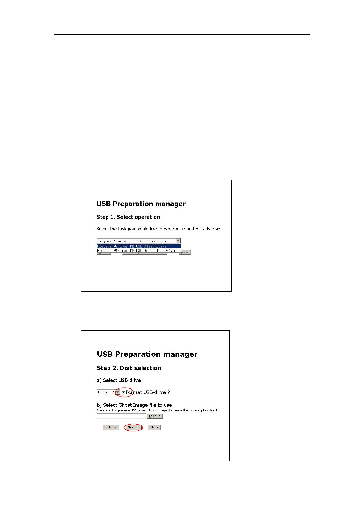
3.13 Imbedded PC System Maintenance
3.13.1 Making USB Startup Disk
Tools required:
MakeUSB (PN: 110-002149-00)
USB drive with capacity greater than 4G.
1. Insert the USB drive into PC.
2. Run “prepareUSB.hta” file in the folder of MakeUSB.
3. Select [Prepare Windows PE USB Flash Drive] in the drop-down list, and select
[Next>].
4. Select the drive label of the USB drive in the drop-down list, and configure [Format
USB-drive?]. [Select Ghost Image file to use] is unselected by default. Then select
[Next>].
3-37
Page 70

5. Select [Prepare USB>] to start making the startup disk. The system selects [Full mode]
and [Manual mode] by default.
6. Select [Close] to finish.
3-38
Page 71

3.13.2 Restoring the System
Connecting the External USB Cable
1. Remove the recorder by referring to chapter Removing the Recorder.
2. Two internal USB cables used for maintenance (PN: 6800-20-50818) appears in the
place where the recorder lies. Connect two external USB cables used for maintenance
(PN: 6800-20-51130) to the two internal USB cables.
3. Connect the USB startup drive containing the system image file (PN: 110-002148-00) to
the external USB cable. Do not use the USB connectors on the rear of the monitor.
Setting BIOS Screen
1. Start up the patient monitor and press [Del] key repeatedly on the keyboard until the
monitor enters normal screen.
2. Select [Main Menu] → [Maintenance>>] → [User Maintenance>>] → enter the
required password → [CIS Maintenance], and the system switches to BIOS setup
screen.
3. Move the cursor to [Advanced BIOS Features] by pressing [↑] or [↓] keys on the
keyboard. Then press [Enter].
4. Move the cursor to [First Boot Device], and press [Enter] on the keyboard.
5. Select [USB-HDD] and press [Enter] on the keyboard.
6. Press [F10] and then [Y] on the keyboard. Save the setup and exit the BIOS setup
screen.
Restoring the system
1. Startup the patient monitor with the USB startup drive. The system enters recovery
screen.
2. Select [Ghost image to disk] in the drop-down list, and then select [Next>] to continue.
3-39
Page 72

3. Select the path of the image file by clicking [File>] button. Then select [Next>].
4. Select [Run>] to begin restoring the system.
3-40
Page 73
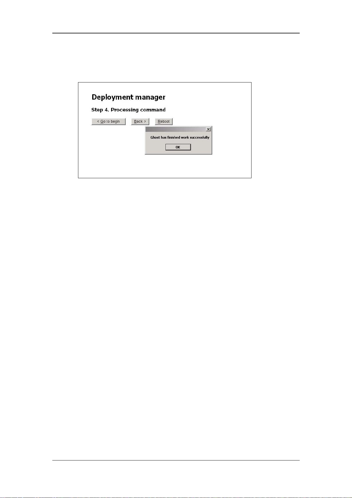
5. Select [Reboot] to restart the system and then remove the USB startup drive after
restoring the system.
6. Set the patient monitor by referring to Steps 1 to 4 of Setting BIOS Screen. Then set
[First Boot Device] to [HDD-0]. Press [F10] and then [Y] on the keyboard. Save the
setup and exit the BIOS setup screen. The system restarts automatically and enters
Windows screen after the setup.
3-41
Page 74

3.14 Factory Maintenance
3.14.1 Accessing Factory Maintenance Menu
To access the factory maintenance menu, select [Main Menu]→ [Maintenance >>] →
[Factory Maintenance]and then enter the required password.
The [Factory Maintenance] menu is shown below.
3.14.2 Drawing Waves
There are two methods to draw waves: Color and Mono.
Color: selecting Color will have smoother waveforms.
Mono: selecting Mono will have a wider viewing angle.
3.14.3 Recorder
To enable/disable the recorder, select [Recorder] and toggle between [On] and [Off].
CAUTION
z The recorder is disabled if [Recorder] is switched off in the [Factory Maintenance]
menu.
3-42
Page 75
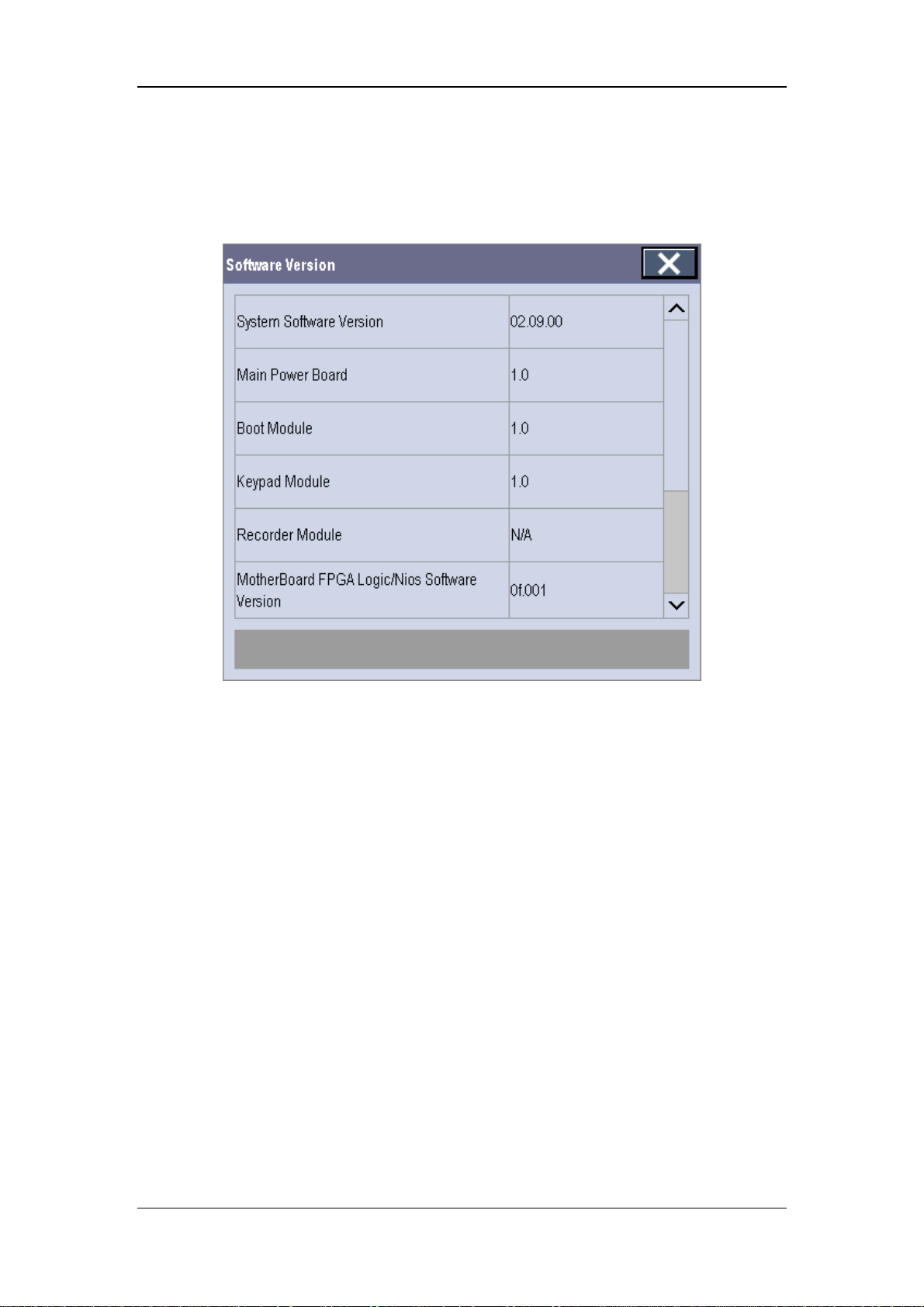
3.14.4 Software Version
Selecting [Software Version] will show software version information. The [Software
Version] menu is as follows:
3-43
Page 76

3.14.5 Monitor Information
Selecting [Monitor Information] will show the status of the patient monitor. Monitor
information is displayed as follows:
3.14.6 Calibrate NIBP
For details, refer to section 3.4.4 NIBP Tests.
3-44
Page 77

Maintenance and Test Report
(See the above sections for detailed test procedures and contents)
Customer name
Customer address
Servicing person
Servicing company
Equipment under test
(EUT)
Model of EUT
SN of EUT
Hardware version
Software version
Test equipment Model/No. Effective date of calibration
Test items Test records Test
results(Pass/Fail)
Visual inspection
The case, display screen, buttons, knob, SMR, modules, power
cord, wall-mount bracket and accessories have no obvious
signs of damage.
The external connecting cables are not frayed and the connector
pins are not loose and bent.
The external connectors are not loose or their pins are not bent.
The safety labels and data plate are clearly legible.
Power-on test
The power-on test is passed. The power indicator and alarm
system work correctly and the monitor start up properly.
Performance test
3-45
Page 78

ECG performance test
ECG waves are displayed correctly without noise and the HR
value is within 80±1 bpm.
ECG Lead Off alarm behaves correctly.
Paced signals are detected and pace pulse marks are displayed
when [Paced] is set to [Yes]
The difference between the amplitude of the ECG calibration
square wave and that of the wave scale is not greater than 5%.
Resp test
The Resp wave is not distorted and the Resp value is within
40±2 rpm.
SpO2 test
Measure SpO2 on a healthy person’s finger and a Pleth wave
and PR value are displayed. The displayed SpO2 value is within
95%-100%
NIBP test
The difference is within ±3 mm when 0, 50 or 200 mmHg is set
for NIBP accuracy test.
There is no leakage with NIBP, or the manual leakage test
result does not exceed 6mmHg/min.
Temp test
The value displayed for each Temp channel of the monitor is
within 37±0.1ºC.
IBP test
The static pressure value displayed for each IBP channel is
within 200±2 mmHg.
The ART and LV waves for each IBP channel are displayed
correctly.
C.O. test
The TB value displayed on the monitor is within 37±0.1ºC.
The displayed C.O. value is within 5±0.25L/min.
Mainstream CO2 test
The mainstream CO2 is zeroed successfully and the waveform
baseline recovers to zero.
CO2 Apnea alarm behaves correctly.
The displayed CO2 value is within 6±0.05%.
3-46
Page 79

Sidestream CO2 test
Block the gas inlet of the module or watertrap. The sidestream
flowrate is slower than 10ml/min and an alarm of CO2
CO
2
Filterline Err is given. It indicates that there is no leakage.
The displayed CO2 value is within 6±0.05%.
Miscrostream CO2 test
Block the gas inlet of the module or watertrap. An alarm of
CO2 Filterline Err is given. It indicates that there is no leakage.
The displayed CO2 value is within 6±0.05%
AG test
When AG flowrate is slower than 10ml/min, an alarm of AG
Airway Occluded is given. It indicates that there is no leakage.
The fan inside the AG module works properly.
The measurement accuracy of CO2, N2O, O2 and AA (AA
represents an anaesthetic agent) meets the product
specifications in the Operator’s Manual.
ICG test
The measured results are as follows: HR=60±2 bpm,
VI=61±4/1000s, TFC=32±2/kOhms.
The measured results are as follows: HR=70±2 bpm, VI=48±4
/1000s, TFC=32±2 / kOhms.
BIS test (you can select either method to perform the test)
Method 1: The BIS value measured on healthy, wide-awake
adult is within 80-100.
Method 2: Connect to the BIS simulator to perform a cyclic
impedance check. The EEG wave and BIS numeric are
displayed on the monitor.
RM test
The displayed TV is within 500±50ml and RR is within
20±1rpm.
CCO/SvO2 test
The CCO/SvO2 numerics displayed on the patient monitor and
Vigilance monitor are consistent.
The waves (at the ECG signal output port) displayed on the
oscillograph are consistent with the ECG calibration waves
displayed on the monitor screen.
3-47
Page 80

The amplitude of electrical level at the signal output port of
MAP, CVP and SpO
are 5±0.25V, 5±0.25V and 10±0.5V
2
Yes N o
respectively.
PiCCO test
The detected catheter type accords with the setting of the
Pulsion Calbox, and the measurement errors of TB and TI are
within ±0.1℃.
The displayed static pressure values of pArt and pCVP are no
more than (200±2) mmHg.
The waveforms of pArt and pCVP are displayed correctly.
ScvO2 test
The accuracy of ScvO2 measurements is (50±3)% and (80±
3)%.
Nurse call relay performance test
The relay contacts are close when an alarm occurs.
Analog output performance test
The waves displayed on the oscillograph are identical with
those displayed on the monitor.
Electrical safety tests
Refer to A Electrical Safety Inspection. All the electrical safety
tests should be passed.
Touchscreen calibration
The touchscreen is calibrated successfully.
Recorder check
The recorder can print ECG waves correctly and the printout is
clear.
Set the recorder to some problems such as out of paper, paper
jam, etc. the monitor gives corresponding prompt messages.
After the problem is removed, the recorder is able to work
correctly.
Automatic alarm recording for each parameter functions
correctly when parameter alarms occur.
Network print test
The network printer can print out ECG reports correctly.
Device integration check
3-48
Page 81

[Devices Integrated] window can display the type of the
external device, ventilation mode, and corresponding
parameters normally.
Battery check
The monitor can operates correctly from battery power when an
AC power failure accidentally occurs.
T5 patient monitor can operate independently on a single
battery.
The operating time of the battery meets the product
specification.
3-49
Page 82

FOR YOUR NOTES
3-50
Page 83

4 Troubleshooting
4.1 Introduction
In this chapter, patient monitor problems are listed along with possible causes and
recommended corrective actions. Refer to the tables to check the patient monitor, identify and
eliminate the troubles.
The troubles we list here are frequently arisen difficulties and the actions we recommend can
correct most problems, but not all of them. For more information on troubleshooting, contact
our Customer Service Department.
4.2 Part Replacement
Printed circuit boards (PCBs), major parts and components in the patient monitor are
replaceable. Once you isolate a PCB you suspect defective, follow the instructions in 5
Repair and Disassembly to replace the PCB with a known good one and check that the
trouble disappears or the patient monitor passes all performance tests. If the trouble remains,
exchange the replacement PCB with the original suspicious PCB and continue
troubleshooting as directed in this chapter. Defective PCB can be sent to us for repair.
To obtain information on replacement parts or order them, refer to 6 Parts.
4.3 Patient Monitor Status Check
Some troubleshooting tasks may require you to identify the hardware version and status of
your patient monitor.
1. To view the information on system start time, self check, etc., select [Main Menu]→
[Maintenance >>]→[Monitor Information >>].
2. You can also view the information on the monitor’s current status by selecting [Main
Menu]→[Maintenance>>]→[Factory Maintenance>>]→enter the required password
→[Monitor Information >>].
4-1
Page 84

4.4 Software Version Check
Some troubleshooting tasks may require you to identify the configuration and software
version of your patient monitor.
1. To view information on the system configuration and system software version, Select
[Main Menu]→[Maintenance>>]→[Software Version>>].
2. You can also view the information on system software version and module software
version by selecting [Main Menu]→[Maintenance>>]→[Factory Maintenance>>]→
enter the required password →[Software Version>>].
4.5 Technical Alarm Check
Before troubleshooting the patient monitor, check for technical alarm message. If an alarm
message is presented, eliminate the technical alarm first. For detailed information on
technical alarm message, possible cause and corrective action, refer to the patient monitor’s
Operation Manual.
4.6 Troubleshooting Guide
4.6.1 Power On/Off Failures
Symptoms Possible Cause Corrective Action
The patient
monitor fails to
start. AC LED
or battery LED
does not light
AC mains not connected
or battery too low
Power supply protection Refer to 4.6.9 Power Supply Failures .
Cables defective or
poorly connected
Power switch & LED
board defective
Power module defective Replace the power module.
Mother board Defective Replace the mother board.
Check that AC mains is properly connected or
battery capacity is sufficient.
1. Check that the cables from power switch & LED
board to button board, button board to main board,
and power module to main board are correctly
connected.
2. Check that cables and connectors are not
damaged.
Replace the power switch & LED board.
4-2
Page 85

4.6.2 Display Failures
Symptoms Possible Cause Corrective Action
Integrated display
is blank but the
patient monitor
still works
correctly.
Secondary display
does not function.
Secondary display
displays snows or
flashing specks
Cables defective or
poorly connected.
Backlight board
defective
Power module defective Replace the power module.
Display defective Replace the display.
Cables defective or
poorly connected.
DVI interface board
defective
Cables defective or
poorly connected.
1. Check that cables from the display to the mother
board and from the backlight board to the button
board/display are correctly connected.
2. Check that the cables and connectors are not
damaged.
Replace the backlight board.
1. Check that the cable between the display and the
patient monitor is correctly connected.
2. Check that the cables and connectors are not
damaged.
Replace the DVI interface board.
1. Check that the cable between the display and the
patient monitor is correctly connected.
2. Check that the cables and connectors are not
damaged.
overlapped or
distorted
Touchscreen does
not response
DVI interface board
defective
The mother board is
damaged.
FPGA error. Update or upgrade FPGA. Images
Cables defective or
poorly connected.
Touchscreen disabled
Replace the DVI interface board.
Replace the mother board.
1. Check that the cable between the display and
mother board is correctly connected.
2. Check that the cables and connectors are not
damaged.
Check if there is a symbol
[Main Menu] QuickKey. If yes, press the [Main
Menu] QuickKey for more than 3s to enable the
touchscreen.
shown above the
4-3
Page 86

Cables defective or
poorly connected.
Touchscreen control
board defective
Button board defective. Replace the button board.
Touchscreen defective. Replace the touchscreen
Mother board defective Replace the mother board
Touch position
invalid
Touchscreen not
calibrated
4.6.3 Module Rack Failures
1. Check that the cables from the touchscreen to the
touchscreen control board, the touchscreen control
board to the button board, and the button board to
the mother board are correctly connected.
2. Check that the cables and connectors are properly
connected
Replace the touchscreen control board
Calibrate the touchscreen
Symptoms Possible Cause Corrective Action
SMR
SMR cannot
identify
parameter
modules
Extension Cable
defective or poorly
connected
Defective parameter
module
Wrong communication
board software revision
Module (in some slots)
unrecognized
1. Check that the cable between SMR and main unit
is properly connected
2. Check that the connecting cables and connectors
are not damaged.
3. Check that contact screws on SMR are tightly
screwed and properly contact the SMR.
Replace the suspicious parameter module with a
known good module. Check if the patient monitor
identifies the replacement module. If yes, it means
that the original one is defective.
Upgrade the program of the module or SMR.
1. Replace the Nios II module.
2. Replace the 8-slot module rack communication
board.
4-4
Page 87

Power supply failure 1. Check if the voltage between two contact screws
in any slot reaches 12V DC. If yes and the
parameter module functions, the PCB assembly in
SRM might fail.
2. If there is no 12 V sent to the SMR, check that
the power module output voltage to the USB
interface board reaches 12V. If yes, the fuse on the
USB interface board might blow. Replace the USB
interface board.
Cable defective or
poorly connected
Nios II module loose or
failure
SMR interface board
failure
SMR communication
board failure
USB interface board
failure
Mother board failure Replace the mother board.
Integral module rack
Integral module
rack cannot
identify
parameter
modules
Module failure Replace parameter module. If a new module is
Cable defective or
poorly connected
1. Check that the cable between SMR interface
board and communication board is properly
connected.
2. Check that connecting cables and connectors are
not damaged.
1. Check that Nios II module is correctly plug ed
2. If the symptom persists, replace the Nios II
module.
Replace the SMR interface board.
Replace the SMR communication board.
Replace the USB interface board.
identified, the original one is defective.
1. Check that the cables from 3-slot module rack
communication board to MPM module rack
communication board, module rack to mother board
are properly connected.
Wrong communication
board software revision
Module (in some slots)
unrecognized
2. Check that connecting cables and connectors are
not damaged.
Upgrade the program of the module or Integral
module rack.
Replace the corresponding module rack
communication board.
4-5
Page 88

Power supply to integral
module rack abnormal
3-slot or MPM module
rack communication
board failure
Nios II module failure Replace the Nios II module.
Mother board failure Replace the mother board.
1. Check if voltage between two contact screws in
any slot reaches 12VDC. If yes and the parameter
module functions, PCB assembly in the SMR might
fail.
2. If there is no 12V sent to the integrated module
rack, check that power module output voltage to
mother board reaches 12V DC. If yes, mother board
might fail.
Replace the 3-slot or MPM module rack
communication board.
4.6.4 Alarm Problems
Symptoms Possible Cause Corrective Action
The alarm lamp
is not light or
extinguished
but alarm
sound is issued
Cable defective or
poorly connected
1. Check that cables from alarm LED board to
button board and button board to mother board are
properly connected.
2. Check that connecting cables and connectors are
not damaged.
No alarm
sound is issued
but alarm lamp
is light
Alarm LED board
failure
Button board failure Replace the button board.
Mother board failure Replace the mother board.
Audio alarm disabled
Cable defective or
poorly connected
FPGA audio logic error Upgrade the audio logic part of the FPGA program.
Speaker failure Replace the speaker.
Replace the alarm LED board.
Select [Main Menu]→[Maintenance >>]→[User
Maintenance >>]→enter the required password→
[Alarm Setup >>], and then in the popup menu, set
[Minimum Alarm Volume] to appropriate setting.
In the [Others] window of the [Alarm Setup]
menu, set [Alm Volume] to appropriate setting.
1. Check that cable between speaker and mother
board is properly connected.
2. Check that connecting cables and connectors are
not damaged.
Mother board failure Replace the mother board.
4-6
Page 89

4.6.5 Button and Knob Failures
Symptoms Possible Cause Corrective Action
Buttons do
not work
Knob does
not work
Cable defective or
poorly connected
Button board failure Replace button board.
Cable defective or
poorly connected
Knob failure Replace the knob encoder.
Button board failure Replace the button board
1. Check that cable between button board and mother
board is properly connected.
2. Check that connecting cables and connectors are not
damaged.
1. Check that cables from knob to button board, and button
board to mother board are properly connected
2. Check that connecting cables and connectors are
undamaged.
4.6.6 Recorder Failures
Symptoms Possible Cause Corrective Action
No printout
Recorder module
disabled
1. Check if the recorder status LED lights
2. If yes, enable the module in [Factory Maintenance ]
menu. Otherwise, check for other possible causes.
Poor print
quality or
paper not
feeding
properly
Paper reversed Re-install the paper roll.
Cable defective or
poorly connected
Recorder power
supply failure
Recorder failure Replace the recorder.
Paper roll not
properly installed
Print head dirty 1. Check the thermal print head and the paper roller for
Print head failure Replace the print head.
Recorder failure Replace recorder.
1. Check that cable between recorder and mother board is
properly connected.
2. Check that connecting cables and connectors are not
damaged.
Check if the power module outputs 5 V DC and 12V DC
correctly.
Stop the recorder and re-install the paper roll.
foreign matter.
2. Clean the thermal print head with an appropriate clean
solution.
4-7
Page 90

4.6.7 Interface Failures
Symptoms Possible Cause Corrective Action
No analog signals or
nurse call signals are
issued
Device with USB port
does not function
(Assume that the
peripheral devices are
good)
Respective output
disabled
DVI interface board
cable loose
DVI interface board
failure
Mother board failure Replace the mother board.
Cable defective or
poorly connected
USB interface board
failure
1. Select [Main Menu]→[Analog Output
Setup]→set [Analog Output] to [On].
1. Check that cable between DVI interface
board and mother board is properly
connected.
2. Check that connecting cables and
connectors are not damaged.
Replace the DVI interface board.
1. Check that cable between USB interface
board and mother board is properly
connected.
2. Check that connecting cables and
connectors are not damaged.
Replace the USB interface board.
Mother board failure Replace the mother board.
4-8
Page 91

4.6.8 CF Card Problems
Symptoms Possible Cause Corrective Action
CF card malfunctions
Wrong CF card or small
memory space
CF card full; data error;
CF card error
CF card failure Replace the CF card.
Cable defective or
poorly connected
CF card board failure Replace the CF card board.
Mother board failure Replace the mother board.
4.6.9 Power Supply Failures
Use only SanDisk-manufactured CF storage
cards. Those with 4GB memory space are
recommended.
Format CF card on PC.
1. Check that the cable between CF card
board and mother board is correctly
connected.
2. Check that connecting cables and
connectors not damaged.
Symptoms Possible Cause Corrective Action
Different battery
voltages
Battery capacity is too
low
Battery cannot be
recharged
Battery failure Replace battery.
Cable defective or
poorly connected
Power board failure Replace the power board.
Battery failure Replace battery.
Cable defective or
poorly connected
Power board failure Replace the power board.
Battery failure Replace battery and recharge the replacement
1. Check that the cable between battery
interface board and power module is
correctly connected.
2. Check that cables and connectors are not
damaged.
1. Check that the cable is correctly
connected.
2. Check that connecting cables and
connectors are not damaged.
battery. If the replacement battery can be
recharged, the original one fails.
4-9
Page 92

No +3.3 V output
No +5.0 V output
No +5.0 V CIS output
No +12 V output
Cable defective or
poorly connected
Power board failure Replace power board
Power supply protection
Power board failure
1. Check that cable between battery interface
board and power module is correctly
connected.
2. Check that cables and connectors are not
damaged.
1. Turn off the monitor then restart it.
2. If the problem remains, disconnect the AC
mains for 5 s and reconnect it, then restart the
patient monitor.
3. If the problem still remains, replace power
board.
NOTE
z When the power module has a failure, it may cause problems to other components,
e.g. the monitor suddenly breaks down during start-up, as the power module may
have a power supply protection. In this case, troubleshoot the power module per
the procedure described in the table above.
z Components of the main unit, SMR and parameter modules are powered by the
power module. In the event that a component malfunctions, check if the operating
voltage is correct. Refer to 2 Theory of Operation for the operating voltage and
measurement points of each comp onent.
4-10
Page 93

4.6.10 Network Related Problems
Symptoms Possible Cause Corrective Action
The patient monitor
cannot be connected to
a CIS.
No connection to LAN 1. Check that the cables and connectors are in
good condition and that the network is
correctly connected.
2. Check that the hub or switch is correctly
configured.
CIS assembly failure 1. Restart the patient monitor, check that a
beep is heard and the CIS fan runs normally
after the system starts up.
2. After starting, select [Main Menu]→
[Maintenance>>]→[User Maintenance>>]
→ enter the password required. In the [User
Maintenance] menu, [CIS Maintenance]
shall be enabled and switching between
normal monitor screen and CIS screen is
possible.
3. If step 1 and 2 fail, check the CIS fan
assembly for damage and if the power supply
to the CIS assembly is correct. If both of
them work correctly, replace the CIS
assembly.
Frequent dropouts and
network disconnects
The patient monitor is
connected to a LAN
but cannot view other
patients under the
View Others mode
DVI interface board
failure
Incorrect LAN cable
connection
Incorrect IP address
configuration
Incorrect LAN cable
connection
Excessive requests for
viewing the patient
monitor at the same time
Incorrect IP
configuration
CIS assembly failure Replace CIS assembly.
Replace DVI interface board.
Check LAN cable connection. LAN cable
shall not be longer than 50 m.
Check for IP address conflict. Reconfigure IP
address.
Check LAN cable connection. LAN cable
shall not be longer than 50m.
A patient monitor can only be viewed by 4
other patient monitors at the same time under
the View Others mode. The excessive view
requests system will be ignored.
Check for IP address conflict. Reconfigure IP
address.
4-11
Page 94

4.6.11 Software Upgrade Problems
Symptoms Possible Cause Corrective Action
Boot file upgrade fails Power failure or
unintended power off
during boot file
upgrade
Program upgrade fails
Incorrect network
connection
Wrong upgrade package
has been downloaded
Incorrect IP address
configuration
Return the CPU board to factory for repair.
1. Check that network connector, not CIS
connector, on the patient monitor is used.
2. Make sure that the hub or switch run
normally. Check that net twines are of the
right type and have been connected
correctly.
Upgrade package shall be .pkg files. Select
package according to system requirement.
Configure a fixed IP address in range C as
specified for the patient monitor. We
recommend not to upgrade a program when
the patient monitor is connected to a
network with multiple PCs.
4.6.12 Technical Alarm Messages
Please refer to the Operator’s manual.
4.6.13 M51A Self Test Information
New MPM module applies the integrative parameter board (ECG ASIC).
MPM Selftest Item Test Value
DSP selftest
information
7024 selftest
information
2131 selftest
information
ECG module selftest
information
Not F
Not 7F
Not 1F
Normal value:7 for
3/5 lead module; FF
for 12-lead module
Test Value (New
MPM module)
Not FF Replace the module
Corrective Action
4-12
Page 95

4.6.14 Device Integration Failures
Symptoms
The [Devices
Integrated]
window displays
nothing after
connection.
Generate the alarm:
[BeneLink Comm
Stop].
The patient monitor
has no response
when loading the
ID adapter.
Possible Cause Corrective Action
1. Replace the ID adapter.
The ID adapter is not
compatible with the
external device.
The serial port adapting
cable is not compatible with
the external device.
The application of the
BeneLink module is
damaged.
The application of the
BeneLink module is
damaged.
The kernel or the document
system of the BeneLink
module is damaged.
2. Upgrade the ID adapter in [Factory
Maintenance] menu to make the ID adapter
match the corresponding external device. See
3.11.1 Device Connection and Setup for
more about the setup of the ID.
Replace the serial port adapting cable.
Update or upgrade the application of the
BeneLink module with the network
upgrading tool.
Update or upgrade the application of the
BeneLink module with the network
upgrading tool.
Return the BeneLink module to factory for
repair.
4-13
Page 96

FOR YOUR NOTES
4-14
Page 97

5 Repair and Disassembly
5.1 Tools
During disassembly and replacing, the following tools may be required:
Phillips screwdrivers
Small flat-bladed screwdrivers
Contact spanner
Tweezers
Sharp nose pliers
Sleeve
5.2 Preparations for Disassembly
Before disassembling the monitor, finish the following preparations:
Stop monitoring the patient, turn off the monitor and disconnect all the accessories and
peripheral devices.
Disconnect the AC power source and take out both of the batteries.
Pull off all the modules in the integral module rack. If the SMR is connected, disconnect
the SMR from the monitor and then remove all the modules in it.
WARNING
z Before disassembling the monitor, be sure to eliminate the static charges first.
When disassembling the parts labeled with static-sensitive symbols, make sure you
are wearing electrostatic discharge protection such as antistatic wristband or
gloves to avoid damaging the equipment.
z Put the cables or wires in place when reassemble the monitor to avoid short circuit.
z When assembling the monitor, be sure to select proper screws. If an unfit screw is
tightened by force, the monitor may be damaged and the screw or the part may fall
off during use to cause unpredictable damage or human injury.
z Be sure to follow the correct sequence to disassembly the monitor. Otherwise, the
monitor may be damaged permanently.
z Be sure to disconnect all the cables before disassembling any parts. Be sure not to
damage any cables or connectors.
z Be sure to place the monitor face up when disassembling it. Otherwise, the screen
or the knob may be scratched or damaged.
5-1
Page 98

5.3 Basic Disassembly
5.3.1 Disconnecting the Base
NOTE
z Be sure to disassemble the base first before proceeding with other parts.
z Be sure to place the monitor face up when disassembling it. If lay the monitor face
down, be sure the surface is non-abrasive and static-free. Otherwise, the screen or
the knob may be scratched or damaged.
1. The hook that prevents the power plug off is located beside the AC port in the rear case
of the monitor. Remove this hook and then place the monitor face up and unscrew the four
M4×12 screws, as shown in the figure below.
5-2
Page 99

2. Pull out the base and then unplug the two cables marked in the picture, one connecting
the Power Switch & LED board and the button board, and the other connecting the battery
interface board and the power supply assembly.
NOTE
z Exercise care when pulling the base out. Be sure not to damage the cables and
connectors.
5-3
Page 100

5.3.2 Separating the Front and Rear Half of the Monitor
1. Keep the monitor (without the base) face up. Disconnect the cables marked in the
picture, one connecting the LCD panel and the mother board, and the other connecting the
button board and the mother board.
NOTE
z Release the clip before disconnecting the cable between the button board and the
mother board.
2. Carefully place the monitor face down. Pry up the four screw covers with a small
flat-bladed screwdriver and unscrew the four M3×12 screws exposed. Then unscrew the
M3×12 screw in the handle.
5-4
 Loading...