

Page 1

T1 Patient Monitor
Operator’s Manual
Page 2

Page 3

T1 Patient Monitor Operator’s Manual I
Copyright 2014 - 2018 Shenzhen Mindray Bio-Medical Electronics Co., Ltd. All rights reserved.
Release time: January 2018
Revision: 8.0
WARNING
Federal Law (USA) restricts this device to sale by or on the order of a physician or other practitioner licensed
by U.S. state law to use or order the use of this device.
Intellectual Property Statement
SHENZHEN MINDRAY BIO-MEDICAL ELECTRONICS CO., LTD. (hereinafter called Mindray) owns the intellectual property
rights to this Mindray product and this manual. This manual may refer to information protected by copyrights or patents
and does not convey any license under the patent rights or copyright of Mindray, or of others.
Mindray intends to maintain the contents of this manual as confidential information. Disclosure of the information in
this manual in any manner whatsoever without the written permission of Mindray is strictly forbidden.
Release, amendment, reproduction, distribution, rental, adaption and translation or any other derivative work of this
manual in any manner whatsoever without the written permission of Mindray is strictly forbidden.
, , and are the trademarks, registered or otherwise, of Mindray in China and other
countries. All other trademarks that appear in this manual are used only for information or editorial purposes. They are
the property of their respective owners.
This posting serves as notice under 35 U.S.C.§287(a) for Mindray patents: http://www.mindrayna.com/patents.
Page 4

II T1 Patient Monitor Operator’s Manual
Manufacturer’s Responsibility
Contents of this manual are subject to changes without prior notice.
All information contained in this manual is believed to be correct. Mindray is not be liable for errors contained herein nor
for incidental or consequential damages in connection with the furnishing, performance, or use of this manual.
Mindray is responsible for the effects on safety, reliability and performance of this product, only if:
all installation operations, expansions, changes, modifications and repairs of this product are conducted by Mindray
authorized personnel;
the electrical installation of the relevant room complies with the applicable national and local requirements;
the product is used in accordance with the instructions for use.
WARNING
Only skilled/trained clinical professionals should operate this equipment.
It is important for the hospital or organization that uses this equipment to perfrom a recommended
service/maintenance plan. Neglect of this may result in machine breakdown or personal injury.
If there is any inconstancy or ambiguity between the latest English version and this manual, the English
version shall prevail.
Warranty
Mindray warrants that components within its products will be free from defects in workmanship and materials for a
period of one year from the date of purchase except that disposable or one-time use products are warranted to be free
from defects in workmanship and materials up to a date one year from the date of purchase or the date of first use,
whichever is sooner.
This warranty does not cover consumable items such as, but not limited to, batteries, external cables, and sensors.
Mindray shall not be liable for any incidental, special, or consequential loss, damage, or expense directly or indirectly
arising from the use of its products. Liability under this warranty and the buyer’s exclusive remedy under this warranty is
limited to servicing or replacing the affected products, at Mindray option, at the factory or at an authorized distributor,
for any product which shall under normal use and service appear to Mindray to have been defective in material or
workmanship. Recommended preventative maintenance, as prescribed in the service manual, is the responsibility of the
user and is not covered by this warranty.
No agent, employee, or representative of Mindray has any authority to bind Mindray to any affirmation, representation,
or warranty concerning its products, and any affirmation, representation or warranty made by any agent, employee, or
representative shall not be enforceable by buyer or user.
Page 5

T1 Patient Monitor Operator’s Manual III
THIS WARRANTY IS EXPRESSLY IN LIEU OF, AND MINDRAY EXPRESSLY DISCLAIMS, ANY OTHER EXPRESS OR IMPLIED
WARRANTIES, INCLUDING ANY IMPLIED WARRANTY OF MERCHANTABILITY, NON-INFRINGEMENT, OR FITNESS FOR A
PARTICULAR PURPOSE, AND OF ANY OTHER OBLIGATION ON THE PART OF MINDRAY.
Damage to any product or parts through misuse, neglect, accident, or by affixing any non-standard accessory
attachments, or by any customer modification voids this warranty. Mindray makes no warranty whatsoever in regard to
trade accessories, such being subject to the warranty of their respective manufacturers.
A condition of this warranty is that the equipment or accessories which are claimed to be defective be returned when
authorized, freight prepaid to Mindray DS USA, Inc., Mahwah, New Jersey 07430 or its authorized representative.
Mindray shall not have any responsibility in the event of loss or damage in transit
Exemptions
Mindray's obligation or liability under this warranty does not include any transportation or other charges or liability for
direct, indirect or consequential damages or delay resulting from the improper use or application of the product or the
use of parts or accessories not approved by Mindray or repairs by people other than Mindray authorized personnel.
This warranty does not extend to:
Malfunction or damage caused by improper use or man-made failure.
Malfunction or damage caused by unstable or out-of-range power input.
Malfunction or damage caused by force majeure events, such as (i) flood, fire and earthquake or other similar
elements of nature or acts of God; (ii) riots, war, civil disorders, rebellions, or revolutions in any country; or (iii) any
other cause beyond the reasonable control of Mindray.
Malfunction or damage caused by improper operation or repair by unqualified or unauthorized service people.
Malfunction of the instrument or part whose serial number is not legible.
Others not caused by instrument or part itself.
Page 6

IV T1 Patient Monitor Operator’s Manual
Service
Mindray maintains a network of service representatives and factory-trained distributors. Prior to requesting service,
perform a complete operational check of the instrument to verify proper control settings. If operational problems
continue to exist,
In North America contact the Service Department at (800) 288-2121, ext: 8116 for Technical Support or (201) 995-8000
for assistance in determining the nearest field service location.
Please include the instrument model number, the serial number, and a description of the problem with all requests for
service.
Any questions regarding the warranty should be directed to your local sales or service representative.
NOTE
Upon request, Mindray provides circuit diagrams, component part lists, descriptions, calibration
instructions, or other information which assist the user’s appropriately qualified technical personnel to
repair those parts of the equipment which are designated by Mindray DS USA, Inc. as repairable.
Page 7

T1 Patient Monitor Operator’s Manual V
Company Contact
Manufacturer: Shenzhen Mindray Bio-Medical Electronics Co., Ltd.
Address: Mindray Building, Keji 12th Road South,Hi-tech industrial park, Nanshan,
Shenzhen 518057,P.R.China
Website: www.mindray.com
E-mail Address: service@mindray.com.cn
Tel: +86 755 81888998
Fax: +86 755 26582680
Distributor: Mindray DS USA, Inc.
Address: 800 MacArthur Boulevard, Mahwah, New Jersey, 07430 USA
Tel: 1.800.288.2121, 1.201.995.8000
Website: www.mindray.com
Page 8

VI T1 Patient Monitor Operator’s Manual
Preface
Manual Purpose
This manual contains the instructions necessary to operate the product safely and in accordance with its function and
intended use. Observance of this manual is a prerequisite for proper product performance and correct operation and
ensures patient and operator safety.
This manual is based on the maximum configuration and therefore some contents may not apply to your product. If you
have any questions, please contact Mindray.
This manual is an integral part of the product. It should always be kept close to the equipment so that it can be
conveniently referenced when needed.
NOTE
If your equipment has any function that is not included in this manual, refer to the latest English version.
Intended Audience
This manual is intended for clinical professionals who are expected to have a corresponding working knowledge of
medical procedures, practices and terminology as required for monitoring of patients.
Illustrations
All illustrations in this manual serve as examples only. They may not necessarily reflect the setup or data displayed on
your monitor.
Conventions
Italic text is used to quote the referenced chapters or sections.
[ ] is used to enclose screen text.
→ is used to indicate operational procedures.
Page 9

T1 Patient Monitor Operator’s Manual 1
Contents
1 Safety ................................................................................................................................................................................. 1-1
1.1 Safety Information .......................................................................................................................................................................................... 1-1
1.1.1 Warnings .............................................................................................................................................................................................. 1-2
1.1.2 Cautions ............................................................................................................................................................................................... 1-3
1.1.3 Notes ..................................................................................................................................................................................................... 1-3
1.2 Equipment Symbols ....................................................................................................................................................................................... 1-4
2 The Basics ........................................................................................................................................................................... 2-1
2.1 Monitor Description ....................................................................................................................................................................................... 2-1
2.1.1 Intended Use ...................................................................................................................................................................................... 2-1
2.1.2 Equipment Features ......................................................................................................................................................................... 2-2
2.1.3 Applied Parts ...................................................................................................................................................................................... 2-2
2.2 Equipment Description ................................................................................................................................................................................ 2-3
2.2.1 Main Unit ............................................................................................................................................................................................. 2-3
2.2.2 T1 handle ............................................................................................................................................................................................. 2-6
2.2.3 T1 Docking Station ........................................................................................................................................................................... 2-7
2.2.4 External Parameter Modules......................................................................................................................................................... 2-8
2.3 Installation ......................................................................................................................................................................................................... 2-9
2.3.1 T1 in Use with the T1 Handle ........................................................................................................................................................ 2-9
2.3.2 T1 Handle in Use with the T1 Docking Station .....................................................................................................................2-10
2.3.3 T1 in Use with the T1 Docking Station ....................................................................................................................................2-11
2.4 Display Screen ................................................................................................................................................................................................2-12
3 Basic Operations ................................................................................................................................................................ 3-1
3.1 Installation ......................................................................................................................................................................................................... 3-1
3.1.1 Unpacking and Checking .............................................................................................................................................................. 3-2
3.1.2 Environmental Requirements ...................................................................................................................................................... 3-2
3.2 Getting Started ................................................................................................................................................................................................ 3-3
3.2.1 Connecting to Power Source ........................................................................................................................................................ 3-3
3.2.2 Turning Power On ............................................................................................................................................................................. 3-4
3.2.3 Starting Monitoring ......................................................................................................................................................................... 3-4
3.3 Turning Off the Monitor ............................................................................................................................................................................... 3-5
3.4 Using the Touchscreen .................................................................................................................................................................................. 3-5
3.5 Using the On-Screen Keyboard ................................................................................................................................................................. 3-6
3.6 Using the External Display ........................................................................................................................................................................... 3-6
3.7 Using the Mouse and Keyboard ................................................................................................................................................................ 3-7
3.8 Using the Main Menu .................................................................................................................................................................................... 3-7
3.9 Changing General Settings ......................................................................................................................................................................... 3-8
3.9.1 Setting Up a Monitor ....................................................................................................................................................................... 3-8
3.9.2 Changing Language ........................................................................................................................................................................ 3-8
3.9.3 Setting the Date and Time ............................................................................................................................................................. 3-8
3.9.4 Setting the Docking Station ......................................................................................................................................................... 3-9
3.10 Setting Parameters ....................................................................................................................................................................................3-10
Page 10

2 T1 Patient Monitor Operator’s Manual
3.10.1 Switching the Parameters On/Off ..........................................................................................................................................3-10
3.10.2 Accessing the Parameters Menu .............................................................................................................................................3-10
3.11 Operating Modes .......................................................................................................................................................................................3-10
3.11.1 Monitoring Mode .........................................................................................................................................................................3-10
3.11.2 Night Mode .....................................................................................................................................................................................3-11
3.11.3 Privacy Mode..................................................................................................................................................................................3-11
3.11.4 Outdoor Mode ...............................................................................................................................................................................3-12
3.11.5 Module Mode ................................................................................................................................................................................3-12
3.11.6 Standby Mode ...............................................................................................................................................................................3-14
4 Managing Patients ............................................................................................................................................................ 4-1
4.1 Admitting a Patient ........................................................................................................................................................................................ 4-1
4.2 Quick Admitting a Patient ........................................................................................................................................................................... 4-2
4.3 Setting the Monitor Location ..................................................................................................................................................................... 4-2
4.4 Querying and Obtaining Patient Information ...................................................................................................................................... 4-2
4.5 Querying from Local Facility ....................................................................................................................................................................... 4-3
4.6 Associating Patient Information ................................................................................................................................................................ 4-3
4.7 Editing Patient Information ......................................................................................................................................................................... 4-3
4.8 Discharging a Patient .................................................................................................................................................................................... 4-4
4.9 Transferring Patient Data ............................................................................................................................................................................. 4-4
4.9.1 Transferring Patient Data via a USB Drive ................................................................................................................................ 4-5
4.9.2 Transferring Patient Data via the T1 to a Host Monitor ....................................................................................................... 4-6
4.10 Auto Deleting History Data from the SD Card ................................................................................................................................... 4-6
4.11 Connecting to a CMS .................................................................................................................................................................................. 4-6
5 Managing Configurations ................................................................................................................................................. 5-1
5.1 Introduction ...................................................................................................................................................................................................... 5-1
5.2 Accessing the [Manage Configuration] Menu ...................................................................................................................................... 5-2
5.3 Changing Department .................................................................................................................................................................................. 5-2
5.4 Setting Default Configuration .................................................................................................................................................................... 5-3
5.5 Saving Current Settings ................................................................................................................................................................................ 5-3
5.6 Editing Configurations .................................................................................................................................................................................. 5-4
5.7 Deleting a Configuration ............................................................................................................................................................................. 5-4
5.8 Transferring a Configuration ....................................................................................................................................................................... 5-4
5.9 Loading a Configuration .............................................................................................................................................................................. 5-5
5.10 Restoring the Latest Configuration Automatically .......................................................................................................................... 5-5
6 User Screens ....................................................................................................................................................................... 6-1
6.1 Adjusting the Screen Brightness ............................................................................................................................................................... 6-1
6.2 Adjusting Volume ........................................................................................................................................................................................... 6-1
6.3 Configuring Your Screens ............................................................................................................................................................................ 6-2
6.3.1 Changing the Waveform Line Size .............................................................................................................................................. 6-2
6.3.2 Changing Measurement Colors ................................................................................................................................................... 6-2
6.3.3 Choosing a Screen ............................................................................................................................................................................ 6-2
6.3.4 Changing the T1 Screen Layout ................................................................................................................................................... 6-3
6.3.5 Changing Screen Layout on the External Display ................................................................................................................. 6-4
Page 11

T1 Patient Monitor Operator’s Manual 3
6.4 Understanding the Big Numerics Screen ............................................................................................................................................... 6-5
6.5 Viewing Minitrends (Only Available with the External Display) ..................................................................................................... 6-5
6.5.1 Having a Split-Screen View of Minitrends ................................................................................................................................ 6-6
6.5.2 Setting Minitrends ............................................................................................................................................................................ 6-7
6.6 Viewing OxyCRG (only available with the external display) ............................................................................................................ 6-7
6.7 Viewing Other Patients (Only Available with the External Display) .............................................................................................. 6-8
6.7.1 Care Group .......................................................................................................................................................................................... 6-8
6.7.2 Viewing the Care Group Overview Bar ...................................................................................................................................... 6-9
6.7.3 Understanding the View Other Patient Window ................................................................................................................... 6-9
7 Alarms ................................................................................................................................................................................ 7-1
7.1 Alarm Categories ............................................................................................................................................................................................ 7-1
7.2 Alarm Levels ...................................................................................................................................................................................................... 7-2
7.3 Alarm Indicators .............................................................................................................................................................................................. 7-2
7.3.1 Alarm Lamp ......................................................................................................................................................................................... 7-2
7.3.2 Alarm Messages ................................................................................................................................................................................ 7-2
7.3.3 Flashing Numeric .............................................................................................................................................................................. 7-3
7.3.4 Audible Alarm Tones ........................................................................................................................................................................ 7-3
7.3.5 Alarm Status Symbols ..................................................................................................................................................................... 7-4
7.4 Alarm Tone Configuration ........................................................................................................................................................................... 7-4
7.4.1 Setting the Minimum Alarm Volume ......................................................................................................................................... 7-4
7.4.2 Changing the Alarm Volume ........................................................................................................................................................ 7-4
7.4.3 Setting the Interval between Alarm Sounds .......................................................................................................................... 7-5
7.4.4 Changing the Alarm Tone Pattern .............................................................................................................................................. 7-5
7.4.5 Setting the Reminder Tones .......................................................................................................................................................... 7-6
7.5 Understanding the Alarm Setup Menu .................................................................................................................................................. 7-6
7.5.1 Setting Alarm Properties for All Parameters ........................................................................................................................... 7-7
7.5.2 Adjusting Alarm Limits Automatically ...................................................................................................................................... 7-7
7.5.3 Setting Alarm Delay Time ............................................................................................................................................................7-10
7.5.4 Setting SpO2 Technical Alarm Delay ........................................................................................................................................7-10
7.5.5 Setting Recording Length ............................................................................................................................................................7-11
7.5.6 Entering CPB Mode (Cardiopulmonary Bypass Mode) .....................................................................................................7-11
7.6 Pausing Alarms ..............................................................................................................................................................................................7-11
7.7 Switching Off All Alarms .............................................................................................................................................................................7-12
7.8 Resetting Alarms ...........................................................................................................................................................................................7-12
7.9 Latching Alarms .............................................................................................................................................................................................7-13
7.10 Testing Alarms .............................................................................................................................................................................................7-14
7.11 Using Care Group Alarms (Only Available with the External Display) .....................................................................................7-15
7.11.1 Care Group Auto Alarms ............................................................................................................................................................7-15
7.11.2 Setting Care Group Alert Tone .................................................................................................................................................7-15
7.11.3 Resetting Care Group Alarms ...................................................................................................................................................7-15
8 Monitoring ECG ................................................................................................................................................................. 8-1
8.1 Introduction ...................................................................................................................................................................................................... 8-1
8.2 Safety ................................................................................................................................................................................................................... 8-1
8.3 Preparing to Monitor ECG ............................................................................................................................................................................ 8-2
Page 12

4 T1 Patient Monitor Operator’s Manual
8.3.1 Preparing the Patient and Placing the Electrodes ................................................................................................................ 8-2
8.3.2 Choosing AHA or IEC Lead Placement ...................................................................................................................................... 8-2
8.3.3 ECG Lead Placements ...................................................................................................................................................................... 8-3
8.3.4 Checking Paced Status .................................................................................................................................................................... 8-4
8.4 Understanding the ECG Display ................................................................................................................................................................ 8-5
8.5 Changing ECG Settings ................................................................................................................................................................................. 8-6
8.5.1 Accessing ECG Menus ..................................................................................................................................................................... 8-6
8.5.2 Setting Pacemaker Rate (For Mortara ECG Algorithm only) .............................................................................................. 8-6
8.5.3 Choosing the Alarm Source .......................................................................................................................................................... 8-6
8.5.4 Changing ECG Wave Settings ....................................................................................................................................................... 8-6
8.5.5 Changing the ECG Filter Settings ................................................................................................................................................ 8-7
8.5.6 Setting the ECG Lead Set ............................................................................................................................................................... 8-7
8.5.7 Choosing an ECG Display Screen ................................................................................................................................................ 8-7
8.5.8 Setting the Notch Filter .................................................................................................................................................................. 8-8
8.5.9 Changing the Pacer Reject Settings ........................................................................................................................................... 8-8
8.5.10 Enabling Smart Lead Off .............................................................................................................................................................. 8-8
8.5.11 Setting the Alarm Level for ECG Lead Off Alarms ............................................................................................................... 8-8
8.5.12 Adjusting QRS Volume ................................................................................................................................................................. 8-9
8.5.13 Adjusting the Minimum QRS Detection Threshold (For Advanced ECG Algorithm Only) ................................... 8-9
8.5.14 About the Defibrillator Synchronization .............................................................................................................................8-10
8.6 About ST Monitoring ...................................................................................................................................................................................8-10
8.6.1 Switching ST Monitoring On and Off ......................................................................................................................................8-11
8.6.2 Understanding the ST Display....................................................................................................................................................8-11
8.6.3 Saving the Current ST Segment as Reference ......................................................................................................................8-12
8.6.4 Changing the Reference Segment ...........................................................................................................................................8-12
8.6.5 Deleting a Reference Segment ..................................................................................................................................................8-12
8.6.6 Changing the ST Alarm Limits ....................................................................................................................................................8-12
8.6.7 Setting the ST Alarm Delay Time ...............................................................................................................................................8-12
8.6.8 Adjusting ST Measurement Points ...........................................................................................................................................8-13
8.7 QT/QTc Interval Monitoring (For Advanced ECG Algorithm Only) .............................................................................................8-14
8.7.1 QT/QTc Monitoring Limitations .................................................................................................................................................8-15
8.7.2 Enabling QT/QTc Monitoring ......................................................................................................................................................8-15
8.7.3 Displaying QT/QTc Parameters and Waveform ....................................................................................................................8-16
8.7.4 Accessing the QT View ..................................................................................................................................................................8-16
8.7.5 Changing QT Settings ...................................................................................................................................................................8-17
8.7.6 Changing QTc Formula .................................................................................................................................................................8-18
8.8 About Arrhythmia Monitoring .................................................................................................................................................................8-18
8.8.1 Understanding the Arrhythmia Events ...................................................................................................................................8-19
8.8.2 Changing Arrhythmia Alarm Settings .....................................................................................................................................8-21
8.8.3 Changing Arrhythmia Threshold Settings .............................................................................................................................8-21
8.8.4 Setting the Extended Arrhythmia (For Advanced ECG Algorithm Only) ....................................................................8-22
8.8.5 Reviewing Arrhythmia Events ....................................................................................................................................................8-22
8.9 ECG Relearning ..............................................................................................................................................................................................8-23
8.9.1 Initiating an ECG Relearning Manually ...................................................................................................................................8-23
8.9.2 Automatic ECG Relearning ..........................................................................................................................................................8-23
8.10 12-Lead ECG Monitoring .........................................................................................................................................................................8-24
Page 13

T1 Patient Monitor Operator’s Manual 5
8.10.1 Setting ECG Waveform Sequence ..........................................................................................................................................8-24
8.10.2 Extending the rhythm lead waveform area ........................................................................................................................8-24
8.11 Resting 12-Lead ECG Analysis ................................................................................................................................................................8-25
8.11.1 Accessing the 12-Lead Screen .................................................................................................................................................8-25
8.11.2 Entering Patient Information ...................................................................................................................................................8-25
8.11.3 12-Lead Setup ................................................................................................................................................................................8-26
8.11.4 Resting 12-lead ECG Analysis ...................................................................................................................................................8-28
8.11.5 12-lead ECG Report ......................................................................................................................................................................8-29
8.12 Troubleshooting .........................................................................................................................................................................................8-30
9 Monitoring Respiration (Resp) ......................................................................................................................................... 9-1
9.1 Introduction ...................................................................................................................................................................................................... 9-1
9.2 Safety Information .......................................................................................................................................................................................... 9-1
9.3 Understanding the Resp Display ............................................................................................................................................................... 9-1
9.4 Placing Resp Electrodes ................................................................................................................................................................................ 9-2
9.4.1 Optimizing Lead Placement for Resp ........................................................................................................................................ 9-2
9.4.2 Cardiac Overlay .................................................................................................................................................................................. 9-2
9.4.3 Abdominal Breathing ...................................................................................................................................................................... 9-3
9.4.4 Lateral Chest Expansion ................................................................................................................................................................. 9-3
9.5 Choosing the Respiration Lead .................................................................................................................................................................. 9-3
9.6 Changing the Apnea Alarm Delay ............................................................................................................................................................ 9-3
9.7 Changing Resp Detection Mode ............................................................................................................................................................... 9-3
9.8 Changing Resp Wave Settings ................................................................................................................................................................... 9-4
9.9 Setting Respiration Rate (RR) Source ....................................................................................................................................................... 9-4
9.10 Setting Alarm Properties ........................................................................................................................................................................... 9-5
10 Monitoring PR ............................................................................................................................................................... 10-1
10.1 Introduction .................................................................................................................................................................................................10-1
10.2 Setting the PR Source ...............................................................................................................................................................................10-1
10.3 Selecting the Active Alarm Source .......................................................................................................................................................10-2
10.4 QRS Tone ........................................................................................................................................................................................................10-2
11 Monitoring SpO2 ............................................................................................................................................................ 11-1
11.1 Introduction .................................................................................................................................................................................................11-1
11.2 Safety ..............................................................................................................................................................................................................11-2
11.3 Identifying SpO2 Modules .......................................................................................................................................................................11-2
11.4 Applying the Sensor ..................................................................................................................................................................................11-2
11.5 Changing SpO2 Settings ..........................................................................................................................................................................11-3
11.5.1 Accessing SpO2 Menus ..............................................................................................................................................................11-3
11.5.2 Adjusting the Desat Alarm ........................................................................................................................................................11-3
11.5.3 Setting SpO2 Sensitivity ............................................................................................................................................................11-3
11.5.4 Changing Averaging Time ........................................................................................................................................................11-3
11.5.5 Monitoring SpO2 and NIBP Simultaneously ......................................................................................................................11-4
11.5.6 Sat-Seconds Alarm Management ...........................................................................................................................................11-4
11.5.7 Changing the Speed of the Pleth Wave ...............................................................................................................................11-5
11.5.8 Zooming PI Value (Only Available with the External Display) ......................................................................................11-5
Page 14

6 T1 Patient Monitor Operator’s Manual
11.5.9 Setting the Alarm Level for SpO2 Sensor Off Alarm ........................................................................................................11-5
11.5.10 Setting the SpO2 Tone Mode ................................................................................................................................................11-5
11.6 Measurement Limitations .......................................................................................................................................................................11-6
11.7 Masimo Information ..................................................................................................................................................................................11-7
11.8 Nellcor Information ...................................................................................................................................................................................11-7
11.9 Troubleshooting .........................................................................................................................................................................................11-8
12 Monitoring NIBP ............................................................................................................................................................ 12-1
12.1 Introduction .................................................................................................................................................................................................12-1
12.2 Safety ..............................................................................................................................................................................................................12-2
12.3 Measurement Limitations .......................................................................................................................................................................12-2
12.4 Measurement Methods ............................................................................................................................................................................12-3
12.5 Setting Up the NIBP Measurement ......................................................................................................................................................12-3
12.5.1 Preparing the Patient ..................................................................................................................................................................12-3
12.5.2 Preparing to Measure NIBP .......................................................................................................................................................12-3
12.5.3 Starting and Stopping Measurements .................................................................................................................................12-4
12.5.4 Correcting the Measurement if Limb is not at Heart Level ..................................................................................................12-4
12.5.5 Enabling NIBP Auto Cycling and Setting the Interval .....................................................................................................12-4
12.5.6 Enabling Measurement on Clock ...........................................................................................................................................12-4
12.5.7 Starting a STAT Measurement ..................................................................................................................................................12-5
12.6 Understanding the NIBP Numerics ......................................................................................................................................................12-5
12.7 Changing NIBP Settings ...........................................................................................................................................................................12-6
12.7.1 Setting the Initial Cuff Inflation Pressure .............................................................................................................................12-6
12.7.2 Setting NIBP Alarm Properties .................................................................................................................................................12-6
12.7.3 Displaying NIBP List .....................................................................................................................................................................12-6
12.7.4 Setting the Pressure Unit ...........................................................................................................................................................12-6
12.7.5 Switching On NIBP End Tone ....................................................................................................................................................12-6
12.8 Assisting Venous Puncture ......................................................................................................................................................................12-7
13 Monitoring Temp ........................................................................................................................................................... 13-1
13.1 Introduction .................................................................................................................................................................................................13-1
13.2 Safety ..............................................................................................................................................................................................................13-1
13.3 Taking a Temp Measurement .................................................................................................................................................................13-1
13.4 Understanding the Temp Display .........................................................................................................................................................13-2
13.5 Setting the Temperature Unit ................................................................................................................................................................13-2
14 Monitoring IBP .............................................................................................................................................................. 14-1
14.1 Introduction .................................................................................................................................................................................................14-1
14.2 Safety ..............................................................................................................................................................................................................14-1
14.3 Zeroing the Transducer ............................................................................................................................................................................14-2
14.4 Setting Up the Pressure Measurement...............................................................................................................................................14-3
14.5 Understanding the IBP Display .............................................................................................................................................................14-4
14.6 Changing IBP Settings ..............................................................................................................................................................................14-4
14.6.1 Changing a Pressure for Monitoring .....................................................................................................................................14-4
14.6.2 Setting Alarm Properties ...........................................................................................................................................................14-5
14.6.3 Changing Averaging Time ........................................................................................................................................................14-5
Page 15

T1 Patient Monitor Operator’s Manual 7
14.6.4 Setting Up the IBP Wave ............................................................................................................................................................14-5
14.6.5 Setting the Pressure Unit ...........................................................................................................................................................14-5
14.6.6 Enabling PPV Measurement and Setting PPV Source .....................................................................................................14-5
14.7 Overlapping IBP Waveforms ...................................................................................................................................................................14-6
14.8 Measuring PAWP (Only Available with the External Display) .....................................................................................................14-7
14.8.1 Preparing to Measure PAWP .....................................................................................................................................................14-8
14.8.2 Setting Up the PAWP Measurement ......................................................................................................................................14-9
14.8.3 Understanding the PAWP Setup Menu ................................................................................................................................14-9
14.9 Troubleshooting ...................................................................................................................................................................................... 14-10
15 Monitoring CO2 .............................................................................................................................................................. 15-1
15.1 Introduction .................................................................................................................................................................................................15-1
15.2 Identifying CO2 Modules ..........................................................................................................................................................................15-2
15.3 Preparing to Measure CO2 .......................................................................................................................................................................15-2
15.3.1 Making a Sidestream CO2 Measurement .............................................................................................................................15-3
15.3.2 Making a Microstream CO2 Measurement ..........................................................................................................................15-4
15.4 Changing CO2 Settings .............................................................................................................................................................................15-4
15.4.1 Accessing CO2 Menus .................................................................................................................................................................15-4
15.4.2 Setting the CO2 Unit ....................................................................................................................................................................15-4
15.4.3 Setting Up Gas Compensations ..............................................................................................................................................15-4
15.4.4 Setting Up Humidity Compensation .....................................................................................................................................15-5
15.4.5 Setting the Apnea Alarm Delay ...............................................................................................................................................15-5
15.4.6 Choosing a Time Interval for Peak-Picking ..........................................................................................................................15-6
15.4.7 Setting the Flow Rate ..................................................................................................................................................................15-6
15.4.8 Setting Up the CO2 Waveform ................................................................................................................................................15-6
15.4.9 Setting RR Source .........................................................................................................................................................................15-6
15.4.10 Barometric Pressure Compensation....................................................................................................................................15-7
15.4.11 Entering the Standby Mode ...................................................................................................................................................15-7
15.5 Measurement Limitations .......................................................................................................................................................................15-8
15.6 Leakage test .................................................................................................................................................................................................15-8
15.7 Troubleshooting the Sidestream CO2 Sampling System .............................................................................................................15-8
15.8 Removing Exhaust Gases from the System ......................................................................................................................................15-9
15.9 Zeroing the Sensor ....................................................................................................................................................................................15-9
15.10 Calibrating the Sensor ............................................................................................................................................................................15-9
15.11 Oridion Information ............................................................................................................................................................................. 15-10
16 Review ............................................................................................................................................................................ 16-1
16.1 Accessing Respective Review Windows .............................................................................................................................................16-1
16.2 Reviewing Graphic Trends.......................................................................................................................................................................16-1
16.3 Reviewing Tabular Trends ........................................................................................................................................................................16-2
16.4 Reviewing Events .......................................................................................................................................................................................16-3
16.4.1 Marking Events ..............................................................................................................................................................................16-3
16.4.2 Reviewing Events .........................................................................................................................................................................16-3
16.5 Reviewing Waveforms ..............................................................................................................................................................................16-5
16.6 Reviewing OxyCRG (Only Available with the External Display) .................................................................................................16-5
Page 16

8 T1 Patient Monitor Operator’s Manual
17 Calculations (Only Available with the External Display) ............................................................................................ 17-1
17.1 Introduction .................................................................................................................................................................................................17-1
17.2 Dose Calculations .......................................................................................................................................................................................17-2
17.2.1 Performing Calculations ............................................................................................................................................................17-2
17.2.2 Selecting the Proper Drug Unit ...............................................................................................................................................17-2
17.2.3 Titration Table ................................................................................................................................................................................17-3
17.2.4 Drug Calculation Formulas .......................................................................................................................................................17-3
17.3 Oxygenation Calculations .......................................................................................................................................................................17-3
17.3.1 Performing Calculations ............................................................................................................................................................17-3
17.3.2 Entered Parameters .....................................................................................................................................................................17-4
17.3.3 Calculated Parameters and Formulas ...................................................................................................................................17-4
17.4 Ventilation Calculations ...........................................................................................................................................................................17-5
17.4.1 Performing Calculations ............................................................................................................................................................17-5
17.4.2 Entered Parameters .....................................................................................................................................................................17-5
17.4.3 Calculated Parameters and Formulas ...................................................................................................................................17-6
17.5 Hemodynamic Calculations ...................................................................................................................................................................17-6
17.5.1 Performing Calculations ............................................................................................................................................................17-6
17.5.2 Entered Parameters .....................................................................................................................................................................17-7
17.5.3 Calculated Parameters and Formulas ...................................................................................................................................17-7
17.6 Renal Calculations ......................................................................................................................................................................................17-8
17.6.1 Performing Calculations ............................................................................................................................................................17-8
17.6.2 Entered Parameters .....................................................................................................................................................................17-8
17.6.3 Calculated Parameters and Formulas ...................................................................................................................................17-9
17.7 Understanding the Review Window ...................................................................................................................................................17-9
18 Printing .......................................................................................................................................................................... 18-1
18.1 Printer .............................................................................................................................................................................................................18-1
18.2 Connecting a printer .................................................................................................................................................................................18-1
18.3 Setting the Printer ......................................................................................................................................................................................18-1
18.4 Starting Report Printouts ........................................................................................................................................................................18-2
18.5 Stopping Report Printouts ......................................................................................................................................................................18-2
18.6 Setting Up Reports ....................................................................................................................................................................................18-2
18.6.1 Setting Up ECG Reports .............................................................................................................................................................18-2
18.6.2 Setting Up Tabular Trends Reports ........................................................................................................................................18-3
18.6.3 Setting Up Graphic Trends Reports .......................................................................................................................................18-3
18.6.4 Setting Up Realtime Reports ....................................................................................................................................................18-3
18.7 End Case Reports ........................................................................................................................................................................................18-3
18.8 Printer Statuses ...........................................................................................................................................................................................18-4
18.8.1 Printer Out of Paper .....................................................................................................................................................................18-4
18.8.2 Printer Unavailable ......................................................................................................................................................................18-4
19 Other Functions ............................................................................................................................................................. 19-1
19.1 Analog Output.............................................................................................................................................................................................19-1
19.2 Exporting the Log ......................................................................................................................................................................................19-1
19.3 Using the Storage Card ............................................................................................................................................................................19-1
19.4 Transferring Data ........................................................................................................................................................................................19-2
Page 17

T1 Patient Monitor Operator’s Manual 9
19.4.1 Data Export System .....................................................................................................................................................................19-2
19.4.2 Transferring Data by Different Means ...................................................................................................................................19-2
19.5 Network Setup ............................................................................................................................................................................................19-3
19.5.1 Setting the Network Type ..........................................................................................................................................................19-3
19.5.2 Wireless Network Connection .................................................................................................................................................19-3
19.5.3 Viewing the MAC Address .........................................................................................................................................................19-6
19.5.4 Enabling the Data Encryption ..................................................................................................................................................19-6
19.5.5 Settting DNS ...................................................................................................................................................................................19-6
19.5.6 Certificates Maintenance ...........................................................................................................................................................19-7
19.5.7 Connecting the Monitor to the CMS .....................................................................................................................................19-7
19.5.8 Setting the Central Stations......................................................................................................................................................19-8
19.5.9 Setting the Network Service Quality Level .........................................................................................................................19-8
19.5.10 Setting the Multicast Parameters .........................................................................................................................................19-9
19.6 MLDAP ............................................................................................................................................................................................................19-9
19.6.1 Setting MLDAP ..............................................................................................................................................................................19-9
19.6.2 Selecting Password for User Authentication ......................................................................................................................19-9
20 Battery ........................................................................................................................................................................... 20-1
20.1 Overview .......................................................................................................................................................................................................20-1
20.2 Safety ..............................................................................................................................................................................................................20-2
20.3 Battery Guidelines ......................................................................................................................................................................................20-2
20.4 Installing or Replacing a Battery ...........................................................................................................................................................20-3
20.5 Charging a Battery .....................................................................................................................................................................................20-3
20.6 Conditioning a Battery .............................................................................................................................................................................20-4
20.7 Checking Battery Performance .............................................................................................................................................................20-5
20.8 Storing a Battery .........................................................................................................................................................................................20-5
20.9 Recycling Batteries .....................................................................................................................................................................................20-6
21 Care and Cleaning ......................................................................................................................................................... 21-1
21.1 General Points .............................................................................................................................................................................................21-1
21.2 Cleaning and Disinfecting the Main Unit/Module/Handle/Docking Station .......................................................................21-2
21.2.1 Approved Cleaning and Disinfecting Agents ....................................................................................................................21-2
21.2.2 Cleaning the Main Unit/Module/Handle/Docking Station ...........................................................................................21-3
21.2.3 Disinfecting the Main Unit/Module/Handle/Docking Station .....................................................................................21-3
21.3 Cleaning and Disinfecting the Accessories .......................................................................................................................................21-4
21.3.1 Approved Accessories Cleaning and Disinfecting Agents ............................................................................................21-4
21.3.2 Cleaning the Accessories ...........................................................................................................................................................21-6
21.3.3 Disinfecting the Accessories.....................................................................................................................................................21-6
21.4 Sterilization ...................................................................................................................................................................................................21-6
22 User Maintenance ......................................................................................................................................................... 22-1
22.1 General Inspection .....................................................................................................................................................................................22-1
22.2 Maintenance and Testing Schedule.....................................................................................................................................................22-2
22.3 Checking Monitor and Module Information ....................................................................................................................................22-3
22.4 ECG Verification ...........................................................................................................................................................................................22-3
22.5 NIBP Leakage Test ......................................................................................................................................................................................22-3
Page 18

10 T1 Patient Monitor Operator’s Manual
22.6 CO2 Leakage Test ........................................................................................................................................................................................22-4
22.7 Calibrating the Touchscreen ...................................................................................................................................................................22-5
23 Accessories..................................................................................................................................................................... 23-1
23.1 ECG Accessories ..........................................................................................................................................................................................23-1
23.2 SpO2 Accessories ........................................................................................................................................................................................23-3
23.3 NIBP Accessories .........................................................................................................................................................................................23-4
23.4 Temp Accessories .......................................................................................................................................................................................23-5
23.5 IBP Accessories ............................................................................................................................................................................................23-6
23.6 CO2 Accessories ...........................................................................................................................................................................................23-6
23.7 Mount and Mounting Accessories .......................................................................................................................................................23-7
23.8 Miscellaneous Accessories ......................................................................................................................................................................23-7
A Product Specifications ...................................................................................................................................................... A-1
A.1 Classifications ..................................................................................................................................................................................................A-1
A.2 Environmental Specifications ....................................................................................................................................................................A-1
A.3 Power Supply Specifications ......................................................................................................................................................................A-2
A.4 Physical Specifications ..................................................................................................................................................................................A-3
A.5 Hardware Specifications ..............................................................................................................................................................................A-3
A.6 Data Storage.....................................................................................................................................................................................................A-5
A.7 Wireless Network ............................................................................................................................................................................................A-5
A.8 Measurement Specifications ......................................................................................................................................................................A-7
B EMC and Radio Regulatory Compliance .......................................................................................................................... B-1
B.1 EMC ...................................................................................................................................................................................................................... B-1
B.2 Radio Regulatory Compliance ................................................................................................................................................................... B-6
B.3 Radio Frequency Radiation Exposure Information ............................................................................................................................ B-6
C Default Configurations ..................................................................................................................................................... C-1
C.1 Parameters Configuration ........................................................................................................................................................................... C-1
C.2 Routine Configuration ............................................................................................................................................................................... C-11
C.3 User Maintenance Items ........................................................................................................................................................................... C-14
D Alarm Messages ............................................................................................................................................................... D-1
D.1 Physiological Alarm Messages ................................................................................................................................................................. D-1
D.2 Technical Alarm Messages ......................................................................................................................................................................... D-3
E Symbols and Abbreviations ............................................................................................................................................. E-1
E.1 Symbols .............................................................................................................................................................................................................. E-1
E.2 Abbreviations ................................................................................................................................................................................................... E-2
Page 19

T1 Patient Monitor Operator’s Manual 1-1
1 Safety
1.1 Safety Information
WARNING
Indicates a potential hazard or unsafe practice that, if not avoided, could result in death or serious injury.
CAUTION
Indicates a potential hazard or unsafe practice that, if not avoided, could result in minor personal injury or
product/property damage.
NOTE
Provides application tips or other useful information to ensure that you get the most from your product.
Page 20

1-2 T1 Patient Monitor Operator’s Manual
1.1.1 Warnings
WARNINGS
Before putting the system into operation, the operator must verify that the equipment, connecting cables
and accessories are in correct working order and operating condition.
To avoid risk of electric shock, this equipment must only be connected to a supply mains with protective
earth. If a properly grounded power outlet is not available, operate the monitor on battery power.
The equipment is not intended to be used within the Magnetic Resonance (MR) environment.
Ensure that the patient monitor is supplied with continuous electric power during work. Sudden power
failure may lead to data loss.
To avoid an explosion hazard, do not use the equipment in the presence of oxygen-rich atmospheres,
flammable anesthetics, or other flammable agents (such as gasoline).
Before connecting the equipment to the power line, check that the voltage and frequency ratings of the
power line are the same as those indicated on the equipment’s label or in this manual.
Do not open the equipment housings. All servicing and future upgrades must be carried out by the
personnel trained and authorized by Mindray only.
Do not come into contact with patients during defibrillation. Otherwise serious injury or death could result.
Do not rely exclusively on the audible alarm system for patient monitoring. Adjustment of alarm volume to
a low level or off may result in a hazard to the patient. Remember that alarm settings should be customized
according to different patient situations and always keeping the patient under close surveillance is the most
reliable way for safe patient monitoring.
PATIENTS WITH A PACEMAKER – On ventricular paced patients, episodes of Ventricular Tachycardia may not
always be detected. Do not rely entirely upon the system’s automated arrhythmia detection algorithm.
Keep pacemaker patients under close surveillance.
The physiological data and alarm messages displayed on the equipment are for reference only and cannot
be directly used for diagnostic interpretation.
To avoid inadvertent disconnection, route all cables in a way to prevent a stumbling hazard. Wrap and
secure excess cabling to reduce risk of entanglement or strangulation by patients or personnel.
Do not touch the equipment’s metal parts or connectors when in contact with the patient; otherwise patient
injury may result.
Never mix patient electrode types or brands. Dissimilar metals or other incompatibilities may cause
considerable baseline drift and may increase trace recovery time after defibrillation.
To reduce the hazard of burns during high-frequency surgical procedure, ensure that the monitor’s cables
and transducers never come into contact with the electro-surgery unit (ESU).
The neutral electrode of the electro-surgery unit (ESU) shall properly contact the patient. Otherwise, burns
may result.
Magnetic and electrical fields are capable of interfering with the proper performance of the equipment. For
this reason make sure that all external devices operated in the vicinity of the equipment comply with the
relevant EMC requirements. Mobile phones and X-ray equipment are a possible source of interference as
they may emit higher levels of electromagnetic radiation.
Page 21

T1 Patient Monitor Operator’s Manual 1-3
1.1.2 Cautions
CAUTIONS
Only use parts and accessories specified in this manual.
Disposable accessories are not designed to be reused. Reuse may cause a risk of contamination and affect
the measurement accuracy.
Always install or carry the equipment properly to avoid damage caused by a drop, impact, strong vibration
or other mechanical force.
Dry the equipment immediately in case of rain or water spray.
When no battery is installed, ensure that the monitor is supplied with continuous electric power during
operation. Sudden power failure may lead to data loss.
This equipment is intended for single patient use.
Store and use the equipment in specified environmental condition. The monitor and accessories may not
meet the performance specification due to aging, stored or used outside the specified temperature and
humidity range.
Disposable accessories are not designed to be reused. Reuse may cause a risk of contamination and affect
the measurement accuracy.
Contact the Mindray service personnel for replacements if you find the housing is broken.
1.1.3 Notes
NOTES
Put the equipment in a location where you can easily view and operate the equipment.
During normal use, the operator is expected to face the front of the equipment.
The equipment uses a mains plug as a means of isolation to the mains power supply. Do not position the
equipment in a place difficult to operate the mains plug.
Remove the battery before shipping the monitor or if it will not be used for an extended period of time.
Keep this manual in the vicinity of the equipment so that it can be conveniently referenced when needed.
The software was developed in compliance with IEC60601-1-4. Therefore, The possibility of hazards arising
from software errors is minimized.
This manual describes all features and options. Your equipment may not have all of them. They are not
available in all geographies.
Remove the battery before shipping the monitor or if it will not be used for an extended period of time.
At the end of its service life, the equipment, as well as its accessories, must be disposed of in compliance
with the guidelines regulating the disposal of such products. If you have any questions concerning disposal
of the equipment, please contact Mindray.
When disposing of the packaging material, be sure to observe the applicable waste control regulations and
keep it out of children’s reach.
Page 22
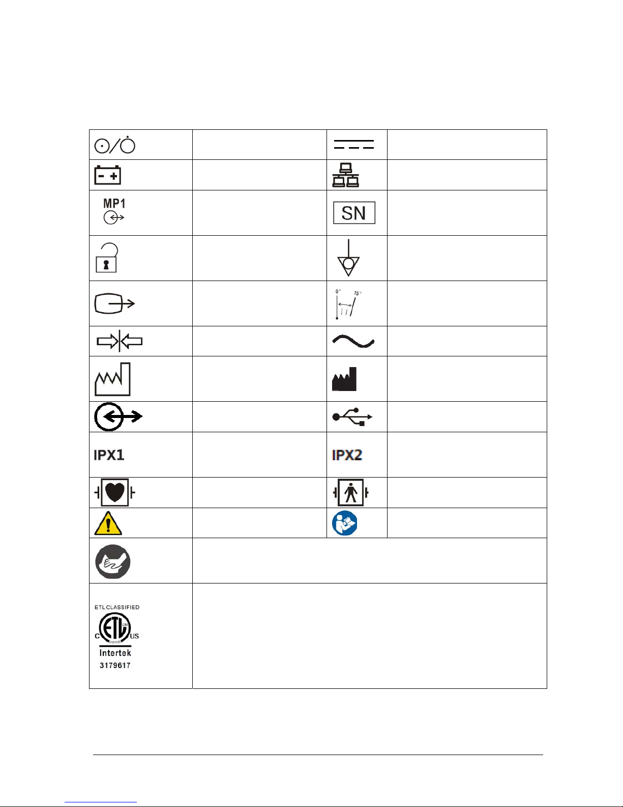
1-4 T1 Patient Monitor Operator’s Manual
1.2 Equipment Symbols
Some symbols may not appear on your equipment.
ON/OFF for a part of equipment
Direct current
Battery indicator
Network connector
Multifunctional connector
Serial number
Unlocking
Equipotentiality
VGA connector
Direction and angle of rotation
Lock; tighten
Alternating current
Date of Manufacture
Symbol for “MANUFACTURER”
Input/output
USB connector
Protected against vertically falling
water drops per IEC 60529
Protected against vertically falling water
drops when ENCLOSURE tilted up to 15°
per IEC 60529
Defibrillation-proof Type CF
applied part
Defibrillation-proof Type BF applied part
General warning sign
Refer to instruction manual/ booklet
Plastics identification symbol
The presence of this label indicates the machine was certified by ETL with the statement:
Conforms to AAMI Std. ES 60601-1, IEC Std. 60601-1-6, IEC Std. 60601-1-8, IEC Std. 60601-2-25,
IEC Std. 60601-2-27, IEC Std. 60601-2-34, IEC Std. 60601-2-49, IEC Std. 80601-2-30, ISO Std.
80601-2-55, ISO Std. 80601-2-56, ISO Std. 80601-2-61
Certified to CSA Std. C22.2 NO. 60601-1, NO. 60601-1-6, NO. 60601-1-8, NO. 60601-2-25, NO.
60601-2-27, NO. 60601-2-34, NO. 60601-2-49, NO. 80601-2-30, NO. 80601-2-55, NO. 80601-2-56,
NO. 80601-2-61
Page 23

T1 Patient Monitor Operator’s Manual 2-1
2 The Basics
2.1 Monitor Description
2.1.1 Intended Use
The T1 Patient Monitor is intended for monitoring, displaying, reviewing, storing , alarming, and transferring of multiple
physiological parameters including ECG (3-lead, or 5-lead, or 12-lead selectable, arrhythmia detection, ST Segment
analysis, QT analysis , and heart rate (HR), respiration rate (Resp), temperature (Temp), pulse oxygen saturation (SpO
2
),
pulse rate (PR), non-invasive blood pressure (NIBP), invasive blood pressure (IBP), pulmonary artery wedge pressure
(PAWP), and carbon dioxide (CO
2
). The equipment also provides an interpretation of resting 12-lead ECG.
All the parameters can be monitored on single adult, pediatric, and neonatal patients with the exception of the
following:
The arrhythmia detection, ST Segment analysis of Mortara ECG algorithm, and PAWP monitoring are intended for
adult and pediatric patients.
ST Segment analysis of Mindray ECG algorithm is intended for adult patients only.
The monitor is to be used in healthcare facilities by clinical professionals or under their guidance. It should only be used
by persons who have received adequate training in its use. It is not intended for helicopter transport, hospital
ambulance, or home use.
WARNING
This patient monitor is intended for use only by clinical professionals or under their guidance. It must only
be used by persons who have received adequate training in its use. Anyone unauthorized or untrained must
not perform any operation on it.
NOTE
Mindray ECG algorithm is hereinafter referred as the Advanced ECG algorithm.
Page 24

2-2 T1 Patient Monitor Operator’s Manual
2.1.2 Equipment Features
The monitor is intended to be used in a hospital environment including, but not limited to, ICU, CCU, PICU, NICU, RICU,
emergency room, operating room, postoperative observation ward, etc.
The monitor can be used in two ways:
As a stand-alone patient monitor, or
As a multi-parameter module (MPM) for the Mindray Passport 17M and Passport 12M patient monitors, hereafter
referred to as “the host monitor”.
In this manual, the T1 is generally referred to as “the monitor” except in the situation describing its use with a host
monitor, where it is referred to as “the T1” to distinguish it from the host monitor.
2.1.3 Applied Parts
The applied parts of the equipment are:
ECG electrodes and leadwires
SpO2 sensor
NIBP cuff
Temp probes
IBP: IBP transducer
CO
2
sampling line/nasal sampling cannula, and water trap
Page 25
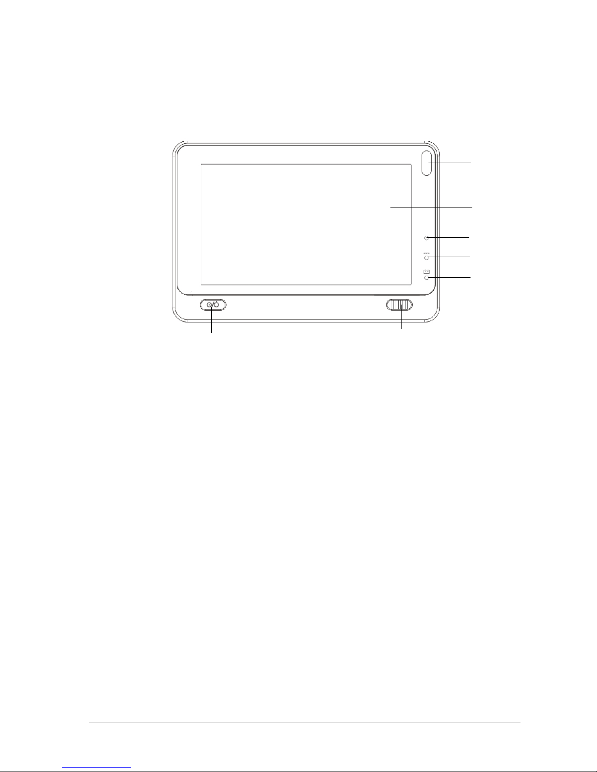
T1 Patient Monitor Operator’s Manual 2-3
2.2 Equipment Description
2.2.1 Main Unit
2.2.1.1 Front View
1. Alarm lamp
When a physiological alarm or technical alarm occurs, this lamp flashes as defined below.
High level alarms: the lamp quickly flashes red.
Medium level alarms: the lamp slowly flashes yellow.
Low level alarms: the lamp lights yellow without flashing.
2. Display Screen
3. Ambient light sensor
When [Brightness] is set to [Auto], the system automatically adjusts the screen brightness according to the
strength of ambient light.
4. External power supply indicator
On: when external DC power supply is connected.
Off: when external DC power supply is disconnected.
5. Battery LED
On: when the battery is installed and the external DC power supply is connected.
Off: when no battery is installed, or the installed battery is malfunctioning, or no external DC power supply is
connected when the monitor is powered off.
Flashing: when the monitor operates on battery power.
6. Power On/Off Switch
Pressing this switch turns the monitor on.
When the monitor is on, pressing and holding this switch turns the monitor off.
An indicator is built into this switch. It turns on when the monitor is on and turns off when the monitor is off.
1
3
4
5
6
2
7
Page 26
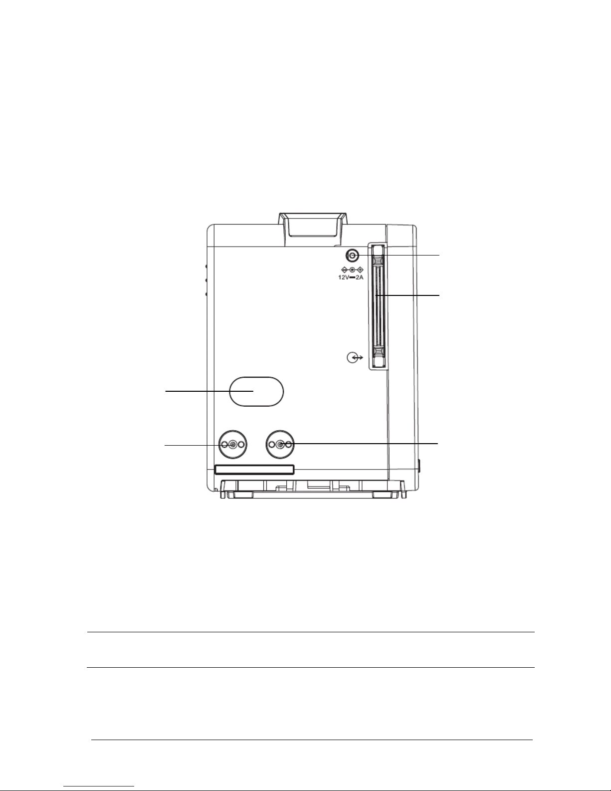
2-4 T1 Patient Monitor Operator’s Manual
7. Lock/unlock switch
When the T1 is not connected with the external display, sliding this switch to the right locks/unlocks the touch
screen.
When the T1 is connected to the external display, sliding this switch to the right switches screen display
between the T1 and the external display.
2.2.1.2 Left View
1. External DC power supply connector
2. Main unit multi-pin connector: connects the T1 to the T1 handle or T1 docking station.
3. Infrared filter: used for communication between the T1 and host monitor.
4. Contact: connects power to the T1 from the T1 docking station or the host monitor.
NOTE
To ensure good contact, clean the contacts regularly, as dust and dirt may collect on them. When cleaning
the contacts, wipe them with cotton, dampened with alcohol. Using forceps is recommended.
1
2
3
4
4
Page 27
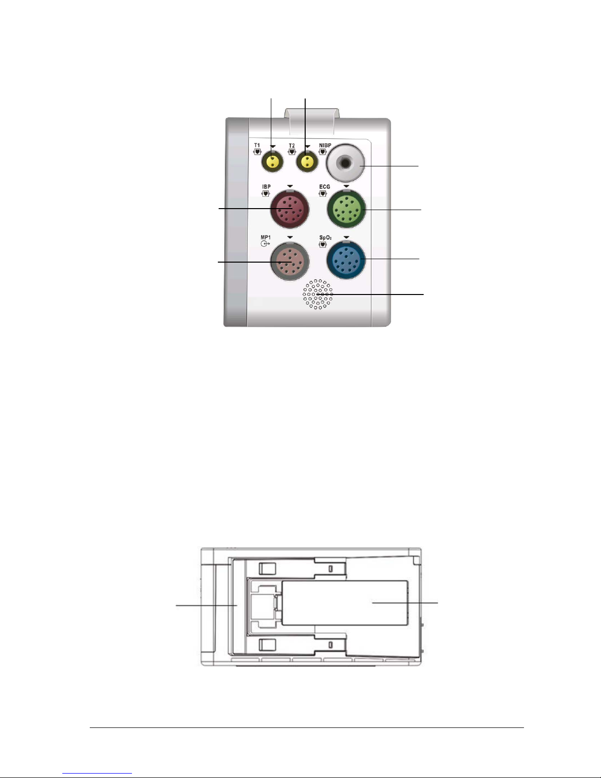
T1 Patient Monitor Operator’s Manual 2-5
2.2.1.3 Right View
1. Temp probe 1 connector
2. Temp probe 2 connector
3. IBP cable connector
4. Multifunctional connector: outputs analog ECG, IBP and defibrillation synchronization signals.
5. NIBP cuff connector
6. ECG cable connector
7. SpO
2
cable connector
8. Speaker
2.2.1.4 Bottom View
1. Latch: locks the T1 when the T1 is in use with the host monitor, the T1 docking station, or the T1 handle. Pressing
here releases the T1 so that you can remove it from the host monitor, the T1 docking station, or the T1 handle.
2. Battery door
1
2
3
4
5
6
7
8
1
2
Page 28
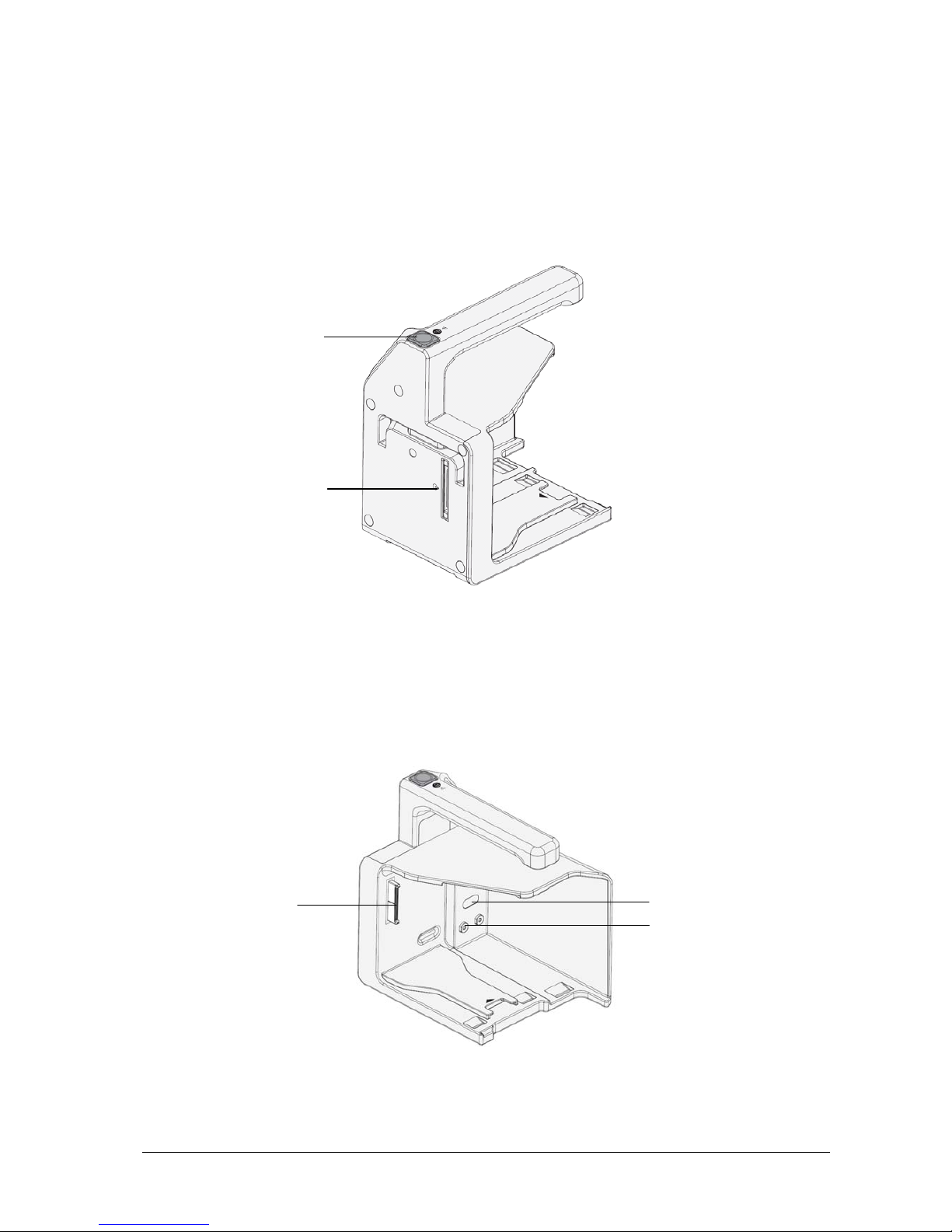
2-6 T1 Patient Monitor Operator’s Manual
2.2.2 T1 handle
The T1 handle is used to connect a T1 and an external parameter module as well as providing bed rail mounting
capability. It can also be connected to the T1 docking station.
2.2.2.1 Left View
1. Release button: pressing this button releases the T1 handle from the T1 docking station.
2. T1 handle multi-pin connector 1: connects the T1 handle and T1 docking station.
2.2.2.2 Right View
T1 handle multi-pin connector 2: connects the T1 handle and the T1.
2. Infrared filter: used for communication between the T1 handle and external parameter module.
3. Contact: power input connector of the external parameter module.
1
2
3
1
2
Page 29
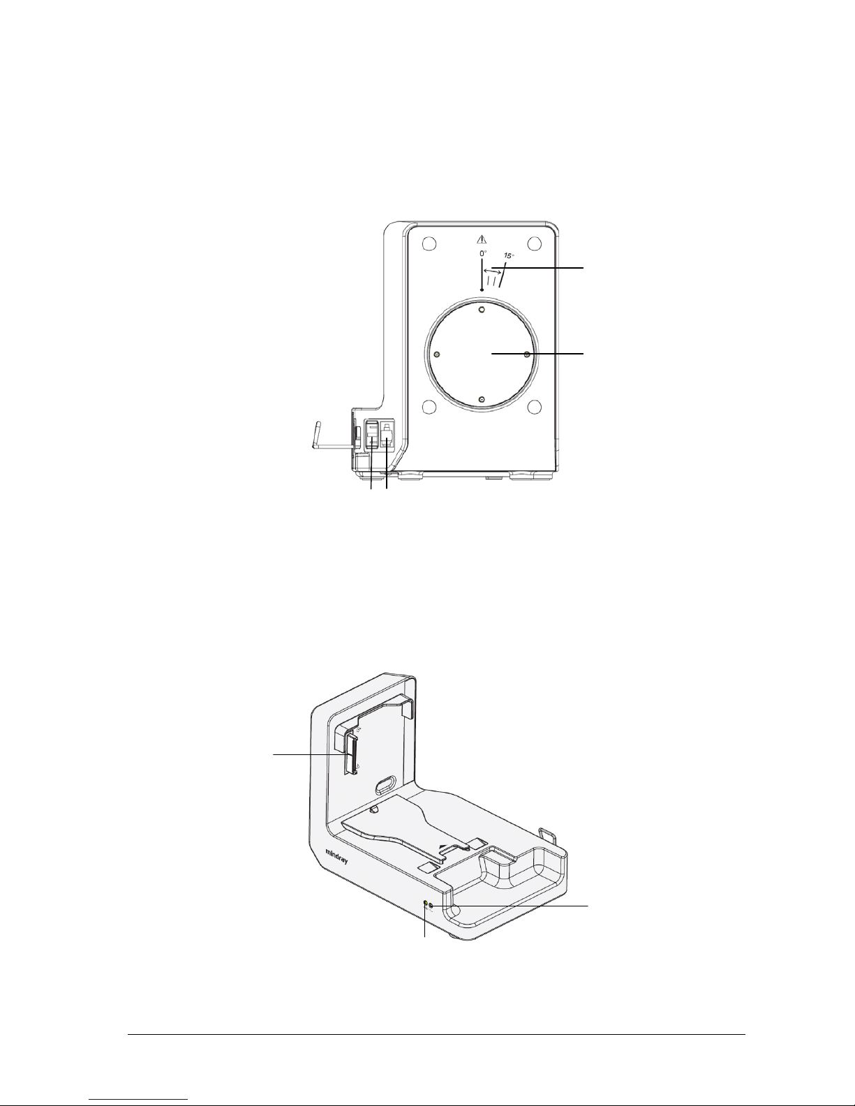
T1 Patient Monitor Operator’s Manual 2-7
2.2.3 T1 Docking Station
The T1 docking station is used to connect the T1 or T1 handle to provide power, charge the installed battery, and
support connection to an external display, USB drive, network cables, and the Passport 12M/17M patient monitors.
2.2.3.1 Left View
1. Symbol: indicates the direction and angle that the T1 docking station can rotate when the T1 docking station is
fixed onto a transverse or a vertical rod.
2. Pole mount seat: used to fix the pole mount to the docking station and then to a transverse or a vertical rod.
2.2.3.2 Right View
1. T1 docking station multi-pin connector: power input and communication connector for the T1
2. Connection status indicator: it is on when the T1 is properly connected to the T1 docking station.
3. External power supply indicator: it is on when the external AC power supply is connected.
1
4
3
1
2
3
2
Page 30
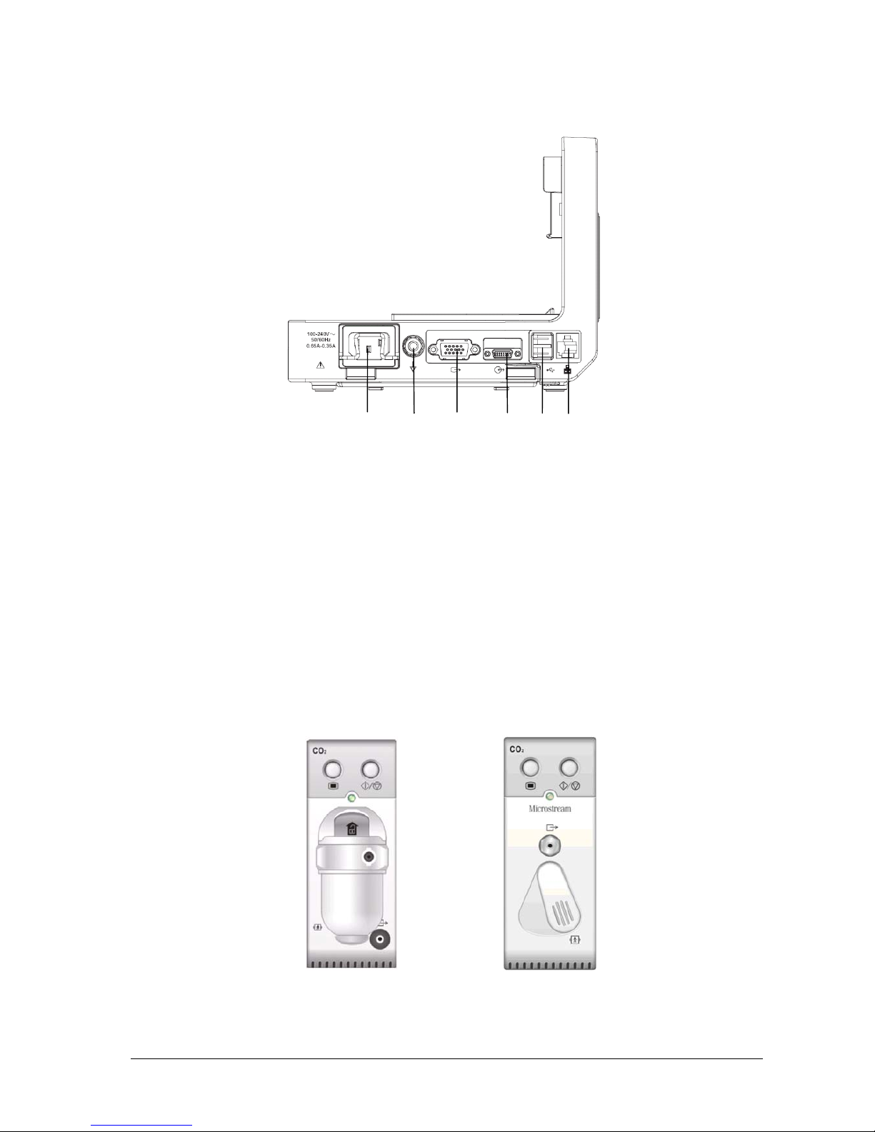
2-8 T1 Patient Monitor Operator’s Manual
5
2.2.3.3 Rear View
1. AC power input
2. Equipotential grounding terminal
When using the monitor together with other devices, connect their equipotential grounding terminals together to
eliminate the potential differences between them.
3. VGA connector: connects the external display
4. External device connector: connects the T1 to the host monitor through a cable.
5. USB connector: connects USB devices, including the USB drive, mouse and keyboard.
6. Network connector: a standard RJ45 connector which connects the monitor to the CMS or CIS. It can also be used to
transfer data.
2.2.4 External Parameter Modules
The monitor can connect the following external parameter modules to perform CO2 monitoring through the T1 handle.
Sidestream CO
2
module Microstream CO2 module
1
2
3
4
6
Page 31

T1 Patient Monitor Operator’s Manual 2-9
2.3 Installation
The T1 handle and T1 docking station are part of the equipment. Use only the specified T1 handle and T1 docking
station.
2.3.1 T1 in Use with the T1 Handle
You can install the T1 and an external parameter module, if needed, to the T1 handle as indicated below:
You hear a click when the T1 or the external module is pushed into place.
CAUTION
When the external module is properly installed, you should further fasten the module to the T1 handle with
the lock at the bottom of the module to ensure the engagement.
To remove the T1 or external parameter module:
1. Press and hold the latch at the bottom of the T1 or parameter module. If the external module is locked to the T1
handle, unlock it first.
2. Pull the T1 or parameter module out as indicated below.
Page 32

2-10 T1 Patient Monitor Operator’s Manual
CAUTION
To prevent the T1 from falling out, do not press the release button while transporting the T1 with the T1
handle.
2.3.2 T1 Handle in Use with the T1 Docking Station
The T1 handle can be installed into the T1 docking station as indicated below:
You hear a click when the T1 handle is pushed into place.
To remove the T1 handle:
1. Press and hold down the release button at the top of the T1 handle.
2. Pull the T1 handle out as indicated.
Page 33

T1 Patient Monitor Operator’s Manual 2-11
2.3.3 T1 in Use with the T1 Docking Station
You can also install the T1 directly to the T1 docking station as indicated below:
You hear a click when the T1 is pushed into place.
To remove the T1 from the T1 docking station:
1. Press and hold the latch at the bottom of the T1.
2. Pull the T1 out as indicated below.
Page 34

2-12 T1 Patient Monitor Operator’s Manual
2.4 Display Screen
This monitor uses a high-resolution TFT LCD to display patient parameters and waveforms. A typical display screen is
shown below.
1. Alarm Symbols
2. Patient Information/Technical Alarm Area
This area shows the patient information such as department, bed number, patient name, patient category and
paced status.
indicates that the patient has an implanted pacemaker. If no patient is admitted, selecting
this area enters the [Patient Setup] menu. For admitted patients, selecting this area enters the [Patient
Demographics] menu.
When a technical alarm is presented, patient information will be covered by the technical alarm message.
When multiple alarms occur, they scroll. Selecting this area shows the Technical Alarms list.
3. Physiological Alarm Area
This area shows physiological alarm messages. When multiple alarms occur, the messages scroll. Select this area
and the physiological alarms list displays.
4. Waveform Area and Parameter Area A
The left side of this area shows measurement waveforms. The right side of this area shows corresponding
measurement parameters. Select this area and the corresponding measurement setup menu displays.
5. Parameter Area B
For the parameter values displayed in this area, their corresponding waveforms are not displayed.
8
1
2
3
4
5
6
7 9
Page 35

T1 Patient Monitor Operator’s Manual 2-13
6. QuickKeys Area
This area contains QuickKeys that provides quick access to functions.
Start or stop NIBP measurements
Reset the alarms
Enter/Exit the alarm paused state
Enter the main menu if no menu is currently displayed. If a menu is didsplayed on the
screen, pressing it closes that menu.
7. Prompt Message Area
This area shows the current configuration name and prompt messages.
8. CMS status area
If the [Select CMS] function is enabled, this area shows the currently selected CMS. If no CMS is selected, this area
displays “???”. Refer to section 19.5.4.1 Selecting a CMS for detail.
9. Status area
This area shows network status, battery status, and system time.
indicates the monitor is successfully connected to a wired network.
indicates the monitor has failed to connect to a wired network.
indicates the wireless function (optional) is connected.
indicates the wireless function (optional) is not connected.
indicates a USB drive is inserted.
For details about battery status symbols, refer to chapter 20 Battery.
Page 36

2-14 T1 Patient Monitor Operator’s Manual
FOR YOUR NOTES
Page 37

T1 Patient Monitor Operator’s Manual 3-1
3 Basic Operations
3.1 Installation
WARNING
Connect only approved devices to this equipment. Devices connected to the equipment must meet the
requirements of the applicable IEC standards (e.g. IEC 60950 safety standards for information technology
equipment and IEC 60601-1 safety standards for medical electrical equipment). The system configuration
must meet the requirements of the IEC 60601-1 medical electrical systems standard. Any personnel who
connect devices to the equipment’s signal input/output port are responsible for providing evidence that the
safety certification of the devices has been performed in accordance to the IEC 60601-1. If you have any
questions, please contact Mindray.
If it is not evident from the equipment specifications whether a particular combination with other devices is
hazardous, for example, due to summation of leakage currents, please consult the manufacturers or else an
expert in the field, to ensure the necessary safety of patients and all devices concerned will not be impaired
by the proposed combination.
CAUTION
The equipment should be installed by Mindray authorized personnel .
NOTE
The software equipment copyright is solely owned by Mindray. No organization or individual shall resort to
modifying, copying, or exchanging it or to any other infringement on it in any form or by any means without
due permission.
Many settings in the patient monitor are password protected. It is recommended to change the default
passwords and keep the passwords safe. Passwords should only be changed by authorized personnel.
Contact your department manager or biomedical engineering department for the passwords used at your
facility.
Page 38

3-2 T1 Patient Monitor Operator’s Manual
3.1.1 Unpacking and Checking
Before unpacking, examine the packing case carefully for signs of damage. If any damage is detected, contact the carrier
or Mindray.
If the packing case is intact, open the package and remove the equipment and accessories carefully. Check all materials
against the packing list and check for any mechanical damage. Contact Mindray in case of any problems.
CAUTION
When disposing of the packaging material, be sure to observe the applicable waste control regulations and
keep it out of children’s reach.
Before use, please verify whether the packages are intact, especially the packages of single use accessories.
In case of any damage, do not apply it to patients.
NOTE
Save the packing case and packaging material as they can be used if the equipment must be reshipped.
3.1.2 Environmental Requirements
The equipment operating environment must meet the requirements specified in this manual.
The equipment operating environment should be reasonably free from noises, vibration, dust, corrosive, flammable and
explosive substances. To maintain good ventilation, the equipment should be at least 2 inches (5 cm) away from
surrounding objects.
When the equipment is moved from one place to another, condensation may occur as a result of temperature or
humidity differences. In this case, never start the system before the condensation evaporates.
CAUTION
Make sure that the equipment operating environment meets the specific requirements. Otherwise un
expected consequences, e.g. damage to the equipment, could result.
Page 39

T1 Patient Monitor Operator’s Manual 3-3
3.2 Getting Started
3.2.1 Connecting to Power Source
Using DC Power Adapter
To connect to the AC mains using the DC power adapter, connect one end of the power cord of the adapter with the DC
power input on the equipment’s back panel and the other end with a wall AC mains outlet.
Using the T1 Docking Station
To connect to the AC power using the T1 docking station:
1. Install the monitor to the T1 docking station as described in section 2.3.3 T1 in Use with the T1 Docking Station.
2. Connect one end of the supplied power cord with the AC power input on the back of the T1 docking station and
the other end with a wall AC mains outlet.
WARNING
Always use the accompanying power cord with the monitor.
Use the battery if the integrity of the protective earth conductor or the protective earthing system in the
installation is in doubt.
Using a Battery
This monitor can be equipped with rechargeable lithium-ion battery. If a battery is installed, the monitor system
automatically switches to the battery for power if AC power is interrupted.
NOTE
When a battery has been stored for a long time, or the battery is depleted, recharge the battery at once.
Otherwise, the low battery may not be sufficient to power the monitor if the AC power is unavailable.
Refer to chapter 20 Battery for detail.
Connecting Accessories
Insert the connector of accessory cables necessary for the measurements to be performed by your monitor to the
corresponding connector on the monitor. For details about the parameter connectors, refer to section 2.2.1.3Right
View.
Page 40

3-4 T1 Patient Monitor Operator’s Manual
3.2.2 Turning Power On
Once the monitor is installed, before beginning measurements:
1. Check the monitor for any mechanical damage, and make sure that all external cables, plug-ins and accessories are
properly connected.
2. Check the power supply specifications are met if mains power is used. Only use a power outlet that is properly
grounded.
3. Connect the power source:
If you are using the DC adapter, plug the DC adapter into the T1.
If you run the monitor on battery power, install the battery and ensure that the battery is sufficiently charged.
If you are using the T1 docking station, install the T1 to the docking station and connect the docking station to
the AC power.
4. Press the power on/off switch on the monitor’s front panel.
The monitor will perform alarm system self-test during start-up. After pressing the power on/off button, the system
shows a “Loading…” screen, sounds a beep and the alarm lamp simultaneously turns yellow, then red, and then turns
off, followed by the start-up screen being shown. Then the start-up screen disappears. The alarm system self-test
succeeds. The monitor enters the normal monitoring screen.
WARNING
Do not use the monitor on a patient if you suspect it is not working properly, or if it is mechanically
damaged. Contact your service personnel or Mindray.
NOTE
Carefully check if the system performs the self-test as described above. Contact your service personnel or
Mindray if the self-test is abnormal.
3.2.3 Starting Monitoring
To start monitoring,
1. Decide which measurements you want to take.
2. Connect the required modules, patient cables, and sensors.
3. Make sure that the patient cables and sensors are correctly connected.
4. Make sure that the patient settings such as [Patient Cat.], [Paced], etc., are appropriate for your patient.
5. Refer to the appropriate measurement section for details of how to perform the measurements you require.
Page 41

T1 Patient Monitor Operator’s Manual 3-5
3.3 Turning Off the Monitor
Before turning off the monitor:
1. Ensure that the monitoring of the patient has been completed.
2. Disconnect the cables and sensors from the patient.
3. Make sure to save or clear the patient monitoring data as required.
4. Press and hold the power on/off switch to turn off the monitor. “System is shutting down…” is displayed on the
screen and then the monitor shuts down.
CAUTION
Press and hold the power on/off switch for 10 seconds to forcibly shut down the monitor if it could not be
shut down normally. This may cause loss of patient data.
The monitor restores the latest configuration if it restarts within 60 seconds after the power failure. And it
will restore the default configuration rather than the latest configuration if it restarts 120 seconds after the
power failure. The monitor loads either the latest configuration or the default configuration if it restarts
from 60-120 seconds after the power failure.
Power failure may cause data corruption on the SD card. It is recommended to turn off the monitor
according to the normal procedures. Do not directly unplug the power cord, unless a charged battery is
installed, or remove the battery before shutting down the monitor.
NOTE
To completely disconnect the power supply, unplug the power cord and then remove the battery.
3.4 Using the Touchscreen
Select screen items by touching them directly on the monitor’s screen.
To avoid misuse, you can lock the touchscreen. If the touchscreen is locked, a message [Screen locked. Please move
the lock/unlock key to unlock the screen] is displayed. The touchscreen is locked automatically if no operation is
detected within 60 seconds.
If the screen is locked, a symbol
is shown in the Main Menu QuickKey area. Sliding the lock/unlock key to the
right unlocks the screen.
Page 42

3-6 T1 Patient Monitor Operator’s Manual
3.5 Using the On-Screen Keyboard
The onscreen keyboard enables you to enter information.
Use the key to delete the previously entered character.
Use the
key to toggle between uppercase and lowercase letters.
Select to confirm what you have entered and close the onscreen keyboard.
Select
to access the symbol keyboard.
Select
to exit the symbol keyboard.
3.6 Using the External Display
The T1 can be connected to an external display through the VGA connector on the T1 docking station. When the
external display is connected, you can monitor a patient either through the T1 or through the external display. Sliding
the lock/unlock switch to the right can switch screen display between the T1 and the external display.
The external display displays different information than the T1 because the external display has a larger screen size. You
can view or operate the following screens or functions only on the external display:
Minitrends Screen
OxyCRG Screen
View Others Screen
ECG 7-Lead Half-Screen
PAWP Screen
Calculations
To connect the external display:
1. Connect one end of the VGA cable to the VGA connector on the T1 docking station and the other end to the
external display.
2. Connect the external display to the AC mains and turn on the display.
3. Connect the T1 to the T1 docking station.
Then you can use the external display to show information from the T1. You can adjust the display by pressing the Auto
Set key on the external display if image offset occurs.
To switch between the T1 and the external display, move the Lock/Unlock switch on the front panel of the T1.
Unplugging the VGA cable of a working external display may result in abnormity. If a problem occurs, remove the T1
from the docking station and reconnect it.
Page 43

T1 Patient Monitor Operator’s Manual 3-7
CAUTION
Only use the display specified by Mindray. Using an unspecified display may result in unknown problems.
3.7 Using the Mouse and Keyboard
When connected to the external display, the T1 can connect a mouse and a keyboard through the USB connector of the
T1 docking station. When a mouse is in use, only the left mouse-button can be used. The right mouse-button is disabled.
3.8 Using the Main Menu
To enter the [Main Menu], select the on-screen QuickKey. Most of monitor operations and settings can be
performed through this menu.
Other menus are similar to the [Main Menu] and contain the following parts:
1. Heading: describes the current menu.
2. Main body: displays options, buttons, prompt messages, etc. The menu button with “>>’’ incorporates a secondary
window to reveal more options or information.
3.
: select to exit the current menu. If changes are made in the menu, they take effect after selecting this button.
4.
and : moves to the next page or previous page to reveal more options or information.
1
2
3
4
Page 44

3-8 T1 Patient Monitor Operator’s Manual
3.9 Changing General Settings
3.9.1 Setting Up a Monitor
To install a monitor or change its location:
1. Select [Main Menu] → [Maintenance >>]→[User Maintenance >>]→enter the required password.
2. In the [User Maintenance] menu, enter the [Monitor Name], [Department] and [Bed No.].
You can set [Changing Bed No.] to:
[Unprotected]: enables you to change Bed No. in the [Patient Demographics] menu.
[Protected]: disables you from changing the Bed No. in the [Patient Demographics] menu.
3.9.2 Changing Language
To change the language:
1. Select [Main Menu]→[Maintenance >>]→[User Maintenance >>]→enter the required password.
2. In the [User Maintenance] menu, select [Language] and then select the desired language.
3. Restart the monitor.
NOTE
The changed language is applied only after the monitor is restarted.
3.9.3 Setting the Date and Time
To set the date and time:
1. Select [Main Menu] →[Maintenance >>]→[System Time >>].
2. Set the date and time.
3. Select [Date Format] and then select [yyyy-mm-dd], [mm-dd-yyyy] or [dd-mm-yyyy].
4. Select [Time Format] and then select [24 h] or [12 h].
If your monitor is connected to a central station (CMS), the date and time are automatically synchronized to that CMS. In
that case, you cannot change the date and time settings on your monitor.
CAUTION
Changing date and time affects the storage of trends and events and may cause data loss. Save or record
any needed data prior to changing the date and time.
Page 45

3.9.4 Setting the Docking Station
To make sure that the T1 can be used with the docking station for the patient transfer, you need to configure the
docking station on the T1.
To configure the docking station, select [Main Menu]→[Maintenance >>]→[User Maintenance >>]→enter the
required password→[Others >>]→[Dock Setup >>].
NOTE
The dock setup function is active only when the T1 is inserted into the docking station.
Setting the Work Mode
Work mode defines the source of facility, department, bed number, central station IP information, and user
authentication service setup (alarm setup, Arrh. alarm settings, user maintenance, local alarm password) when the T1 is
connected with the docking station.
The Dock mode and host mode have the following features:
In Dock mode, the T1 uses the settings of the T1 when the T1 is connected, and the settings on the docking station
remain unchanged whether the T1 is connected or removed.
In host mode, the T1 uses the settings of the docking station when the T1 is connected, and the settings of the T1
when the T1 is removed from the docking station.
NOTE
The Work mode is from the perspective of the docking station. When [Dock Mode] is selected, the docking
station works only as a Dock. When [Host Mode] is selected, the docking station acts as the Host.
Setting Network Type
Network Type specifies the source of the T1’s network configuration when the T1 is connected with the docking station.
If [Use Current T1 Net Setting] is selected, the T1’s network setting is the current T1’s network setting when the T1
is connected, and the setting does not change when the T1 is removed from the docking station.
If [Use Current Dock Net Setting] is selected, the T1’s network setting is the current network setting of the docking
station, and the setting is restored to the previous T1’s settings when the T1 is removed from the docking station.
T1 Patient Monitor Operator’s Manual 3-9
Page 46

3-10 T1 Patient Monitor Operator’s Manual
Setting the IP for CMS
The IP of the CMS defines the IP address of the CMS to which the T1 is connected. The T1 can only be connected to the
specified CMS.
The IP address of the current CMS is shown in the prompt message area. You can select this area to pop up the [Central
Station IP] menu.
NOTE
For the DPM Central Station with system software version 01.01.00 or greater, as long as a patient is
admitted, the T1 can be automatically connected to DPM Central Station.
For the Panorama Central Station with a system software version 11.5 or greater, as long as the device ID of
the T1 has been added to the equipment list and a patient is admitted, the T1 can be connected to
Panorama Central Station.
3.10 Setting Parameters
3.10.1 Switching the Parameters On/Off
To switch the parameters on or off, select [Main Menu]→[Screens]→[Parameters Switch]. When a parameter is
switched off, its corresponding parameter module stops working, and its parameter value and waveform are not shown
on the monitor display.
NOTE
ECG is always selected, and you cannot switch it off.
3.10.2 Accessing the Parameters Menu
Select [Parameters >>] from the [Main Menu] or select corresponding parameter area or waveform area to access a
parameter setup menu.
3.11 Operating Modes
Your monitor has different operating modes. Some are password protected. This section lists the major operating
modes.
3.11.1 Monitoring Mode
This is the standard working mode that you use for monitoring patients. Your monitor automatically enters the
Monitoring mode after being turned on.
Page 47

T1 Patient Monitor Operator’s Manual 3-11
3.11.2 Night Mode
To avoid disturbing the patient, the Night mode may be used.
To activate the Night mode:
1. Select [Main Menu]→[Screen Setup >>]→[Night Mode >>].
2. In the pop-up menu, set the desired brightness, alarm volume, QRS volume, key volume, NIBP end tone, and
whether to stop NIBP measurements or not. When [Stop NIBP] is selected, all the NIBP measurements terminate
after entering the Night mode.
3. Select the [Enter Night Mode] button.
To cancel the Night mode:
1. Select [Main Menu]→[Screen Setup >>]→[Night Mode >>].
2. Select [Ok] in the pop-up.
CAUTION
Before entering Night mode, confirm the brightness settings, alarm volume, QRS volume, and key
volume. Consider the potential risk when the setting value is low.
3.11.3 Privacy Mode
The Privacy mode is available only when an admitted patient at a monitor is also monitored by the CMS.
To activate the Privacy mode, select [Main Menu]→[Screen Setup >>]→[Privacy Mode].
The monitor does the following after activating the Privacy mode:
The screen turns blank and the message [Under monitoring. Press any key to exit the Privacy mode] displays.
Monitoring and data storing continue but patient data is only visible at the CMS.
Alarms can still be triggered. But all audible alarms are suppressed and the alarm light is deactivated at the monitor.
All system sounds are suppressed, including heart beat tone, pulse tone, all prompt tones, etc.
To cancel the Privacy mode, press any key.
The monitor exits the Privacy mode automatically in any of the following situations:
The monitor disconnects from the CMS.
The alarm [Battery Too Low] or [System will shut down soon. Please replace the batteries or use the external
power] is presented.
The touchscreen is locked automatically in the Privacy mode.
Page 48

3-12 T1 Patient Monitor Operator’s Manual
WARNING
In the Privacy mode, all audible alarms are suppressed and the alarm light is deactivated at the monitor.
Alarms sound only at the CMS.
NOTE
The Privacy mode can be used only when the monitor is connected to a CMS.
3.11.4 Outdoor Mode
The Outdoor mode is intended for transporting patients in bright ambient light conditions. In this mode, the parameter
color is white and unchangeable, and the screen brightness automatically changes to 10, the brightest.
To activate the Outdoor mode, select [Main Menu]→[Outdoor Mode].
You can also select [Main Menu]→[Maintenance >>]→[User Maintenance >>]→enter the required password. In the
[Others >>] menu, set [Outdoor Mode] to:
[Manual]: the monitor enters the Outdoor mode by manually selecting [Main Menu
→
][Outdoor Mode], or
[Auto]: the monitor enters the Outdoor mode automatically if the strength of ambient light is greater than the
threshold for more than 5 seconds.
To exit Outdoor mode, select [Main Menu]→[Outdoor Mode]. The monitor automatically exits the Outdoor mode
when:
The T1 is connected to a host monitor.
The strength of ambient light is lower than the threshold for more than 5 seconds and the [Outdoor Mode] is
set to [Auto].
3.11.5 Module Mode
When the T1 is connected to a host monitor, it works as the host monitor’s parameter module. The T1 can be connected
to the host monitor either through the internal or satellite module rack of the host monitor or through the T1 docking
station.
When the T1 is connected to the host monitor through the internal or satellite module rack, the T1 screen is disabled.
When the T1 is detached from the host monitor, it returns to normal Monitoring mode. When the T1 is connected to the
host monitor through the T1 docking station, some functions, including setting alarms, parameters, patient information,
etc., can be achieved by operating either the host monitor or the T1. Refer to the host monitor’s operating manual for
details.
Page 49

T1 Patient Monitor Operator’s Manual 3-13
Insert the T1 in the module rack of the host monitor
To use the T1 with the host monitor, insert the T1 into the host monitor’s internal module rack or satellite module rack.
Firmly push the T1 until you hear that the clip engages the module rack. To ensure that the T1 is properly connected, try
to pull the T1 outward. The T1 is properly engaged in the module rack if you cannot pull the T1 out.
CAUTION
To prevent the T1 from falling out, after inserting the T1 into the module rack, always check that the T1
properly engages into the module rack.
To remove the T1 from the host monitor, lift the latch (refer to 2.2.1.4 Bottom View) at the bottom of the T1 and pull the
T1 out.
Connect the T1 with the host monitor through the docking station
To connect the T1 docking station to the host monitor:
1. Connect the T1 dock data cable (PN: 009-003591-00 or 009-003592-00) to the external device connector of the T1
docking station.
2. Connect the T1 dock data cable to the SMR connector of the host monitor.
To disconnect the T1 docking station from the host monitor:
1. Disconnect the T1 dock data cable from the host monitor.
2. Disconnect the T1 dock data cable from the T1 docking station.
WARNING
Do not unplug the T1 dock data cable during normal use. It may result in unknown problems.
Make sure that the T1 dock data cable is disconnected from the host monitor when the T1 docking station is
not in use with the host monitor.
Page 50

3-14 T1 Patient Monitor Operator’s Manual
3.11.6 Standby Mode
In the Standby mode, you can temporarily stop patient monitoring without turning off the monitor.
To enter the Standby mode:
1. Select [Main Menu]→[Standby].
2. Select [Yes] in the pop-up menu.
Page 51

T1 Patient Monitor Operator’s Manual 4-1
4 Managing Patients
4.1 Admitting a Patient
The monitor displays and stores physiological data in trends as soon as a patient is connected. This allows you to
monitor a patient that is not admitted yet. However, it is recommended that you fully admit a patient so that you can
clearly identify them on reports and network devices.
To admit a patient:
1. Select [Main Menu]→[Patient Setup >>].
2. Select [Admit Patient].
If a patient has previously been admitted, a message [Are you sure to discharge the current patient and admit a
new patient?] pops up. Then select [Ok] to clear any previous patient data. If you do not erase data from the
previous patient, the new patient’s data is combined with the previous patient’s data. The monitor makes no
distinction between the old and the new patient data.
If no patient has been previously admitted, you can choose either:
[Yes] to apply the data saved in the monitor to the new patient, or
[No] to clear the data saved in the monitor.
3. In the [Patient Demographics] menu, enter the demographic details, of which:
[Patient Cat.] allows the user to select patient size (Neo, Ped, Adu) which will determine the way your monitor
processes and calculates some measurements, and what safety and alarm limits are applied to your patient.
[Paced] determines whether to show pace pulse marks on the ECG waveform. When the [Paced] is set to [No],
pace pulse marks are not shown in the ECG waveform.
4. Select [Ok].
WARNING
Make sure the [Patient Cat.] and [Paced] fields always contain a value, regardless of whether the patient is
fully admitted or not.
For paced patients, you must set [Paced] to [Yes]. If it is incorrectly set to [No], the monitor could mistake a
pace pulse for a QRS and fail to alarm when the ECG signal is too weak.
For non-paced patients, you must set [Paced] to [No].
For details about patient paced status, refer to section 8.3.4 Checking Paced Status.
Page 52

4-2 T1 Patient Monitor Operator’s Manual
4.2 Quick Admitting a Patient
Use [Quick Admit] only if you do not have the time or information to fully admit a patient. Complete the rest of the
patient demographic details later.
To quick admit a patient:
1. Select [Main Menu]→[Patient Setup >>].
2. Select [Quick Admit]. If a patient has previously been admitted, select [Ok] to discharge the current patient. If no
patient has previously been admitted, you can choose either:
[Yes] to apply the data in your monitor to the new patient, or
[No] to clear any previous patient data.
3. Enter the Patient Category and Paced Status for the new patient, and then select [Ok].
4.3 Setting the Monitor Location
To set the monitor location, follow this procedure:
1. Select [Main Menu]→[Maintenance >>]→[User Maintenance >>]→enter the required password.
2. Input the following location of the monitor:
[Facility]: your facility name.
[Department]: your department name.
[Room No.]: room number.
[Bed No.]: bed number.
4.4 Querying and Obtaining Patient Information
The monitor can obtain patient information from the Hospital Information System (hereafter called HIS) through the
eGateway. To query or obtain patient information from the HIS:
1. Select [Main Menu]→[Maintenance >>]→[User Maintenance >>]→enter the required password→[Network
Setup >>]→[Gateway Comm Setup >>], and set [Server Address] and [Port]. Set [ADT Query] to [On]. Then select
[Ok].
2. Select the patient information area to enter the [Patient Demographics] menu.
3. Select [Obtain Patient Info. >>] to enter the [Obtain Patient Information] menu.
4. Input a query condition and then select [Query]. The monitor displays the requested patient information.
5. Select a patient and then click [Import] to update the corresponding patient information.
6. Select to exit the [Obtain Patient Information] menu.
Page 53

T1 Patient Monitor Operator’s Manual 4-3
NOTE
The option [Obtain Patient Information] is available in the [Patient Setup] menu only when [ADT Query] is
set to [On].
When obtaining patient information from the HIS, only patient information is updated onthe monitor. The
patient’s physiological data is not changed and the patient is not discharged.
4.5 Querying from Local Facility
You can query the patient information from either the local facility or all networked facilities. To set where to query,
follow this procedure:
1. Select [Main Menu]→[Maintenance >>]→[User Maintenance >>]→enter the required password→[Network
Setup >>]→[Gateway Comm Setup >>].
2. Set [Query From Local Facility].
Select [Yes] to query only from local facility.
Select [No] to query from all networked facilities.
4.6 Associating Patient Information
After associating patient information with the HIS, the monitor automatically updates the patient information if the
corresponding HIS information changes. The monitor can associate the patient’s MRN(Medical Record Number), visit
number, first name, last name, date of birth, and gender with the HIS.
NOTE
A keyword takes effect only when being defined in the eGateway. Refer to eGateway Integration Manager
Installation Guide (P/N: 046-002447-00) for details.
The monitor displays corresponding patient information only when all the keywords have been entered.
4.7 Editing Patient Information
To edit the patient information after a patient has been admitted, or when the patient information is incomplete:
1. Select [Main Menu]→[Patient Setup >>].
2. Select [Patient Demographics] and then make the required changes.
3. Select [Ok].
Page 54

4-4 T1 Patient Monitor Operator’s Manual
You can also input the patient’s visit number in the [Patient Demographics] menu, but the [Visit Number] option
needs to be enabled.
To display the [Visit Number] option in the [Patient Demographics] menu:
1. Select [Main Menu]→[Maintenance >>]→[User Maintenance >>]→enter the required password.
2. Set [Visit Number] to [On >>].
4.8 Discharging a Patient
To discharge a patient:
1. Select [Main Menu]→[Patient Setup >>].
2. Select [Discharge Patient]. In the pop-up menu, you can either:
Select [Ok] to discharge the current patient, or
Select [Standby] then [Ok]. The monitor enters the standby mode after discharging the current patient, or
Select [Cancel] to exit without discharging the patient.
If you need to print the end case report, refer to section 18.7 End Case Reports for instructions.
NOTE
After discharging an admitted patient, you can review the history data of this patient by selecting [Main
Menu]→[Patient Setup >>]→[History Data>>] When the SD card is full, the oldest patient data will be
deleted automatically. Therefore, you cannot always view all the history data.
4.9 Transferring Patient Data
You can transfer patient data between monitors without re-entering the patient demographic information. Transferring
of patient data enables you to review the patient’s history. The patient data that can be transferred includes: patient
demographics, trend data, alarm events and parameters alarm limits.
You can use a USB drive to transfer data between two monitors. You can also connect the T1 with the host monitor to
implement patient transfer. Refer to the operator manual of the host monitor.
WARNING
Do not discharge a patient before the patient is successfully transferred.
After a patient is successfully transferred, check if the patient settings (especially patient category, paced
status and alarm limits settings, etc.) on the monitor are appropriate for this patient.
NOTE
The system automatically enables the HR alarm and lethal arrhythmia alarm after transferring the patient
data.
Page 55

T1 Patient Monitor Operator’s Manual 4-5
4.9.1 Transferring Patient Data via a USB Drive
To transfer patient data to a USB drive:
1. Select [Others >>] from the [User Maintenance] menu.
2. In the pop-up menu, set [Data Transfer Method] to [USB Drive].
You can also set [Transferred Data Length]. The default is [4 h].
4.9.1.1 Transferring Data from the Monitor to a USB Drive
To transfer data from the monitor to a USB drive:
1. Connect the T1 to the T1 docking station.
2. Connect a USB Drive to the T1 docking station’s USB connector.
3. Select [Main Menu]→[Patient Setup >>].
4. Select [Transfer to Storage Medium]. In the pop-up menu, select [Ok].
5. Wait until the following message appears: [Transfer to storage medium successful. Please remove the USB
drive.].
6. Remove the USB drive from the T1 docking station.
4.9.1.2 Transferring Data from a USB Drive to the Monitor
To transfer data from a USB drive to the monitor:
1. Connect a USB Drive to the T1 docking station’s USB connector.
2. Select [Main Menu]→[Maintenance >>]→[User Maintenance >>]→enter the required password → [Others >>]
→ [Data Transfer Method] →[USB Drive]. Then:
Select [Transfer] to transfer the patient data to the monitor, or
Select [Cancel Transfer] to cancel the transfer operation, or
Select [Unload USB Drive] to keep the patient data and to unload the USB drive without transferring the
patient data..
3. After you select [Transfer], in the pop-up menu you can select the patient data content that need to be transferred.
[Patient Demographics] must be selected. After selecting [Ok], the monitor compares the patient information
stored in both the storage medium and monitor and manages the patient data based on the following:
Different Patients:
The monitor erases all the current patient data, transfers the patient data from the
storage medium, and loads the configuration according to the patient category.
Same Patient:
In the pop-up dialog box, you can:
Select [Yes] to merge the patient data in the monitor and storage medium.
Select [No] to erase all the current patient data in the monitor and to
transfer the patient data from the storage medium.
4. Wait until the message [Transfer from storage medium successful.] appears before removing the USB drive.
Page 56

4-6 T1 Patient Monitor Operator’s Manual
CAUTION
The USB drive you use may be write-protected. In this case, make sure the USB drive is in read/write mode.
Do not remove the storage medium during the data transfer process. Otherwise, data files may be damaged.
Check that the USB drive is removed before disconnecting the T1 from the T1 docking station.
The normal monitoring function will be affected during data export. Do not perform any monitoring activity
during data export.
4.9.2 Transferring Patient Data via the T1 to a Host Monitor
The T1 can be used with a host monitor to implement patient transfer. For patient transfer via the host monitor, refer to
the host monitor’s operating manual (PN: 046-005013-00) for detail.
4.10 Auto Deleting History Data from the SD Card
When the free space on the SD card is low, the monitor automatically deletes all patient history data, except the data of
the currently monitored patient and the last patient monitored. If the free space on the SD card is still low after the auto
deleting, the monitor will trigger a technical alarm to prompt: [Storage Card Space Low]. For details about the technical
alarm, refer to section 0
Technical Alarm Messages.
4.11 Connecting to a CMS
The monitor supports connection to a CMS. If your monitor is connected to a CMS:
All patient information, measurement data and settings on the monitor can be transferred to the CMS.
All patient information, measurement data and settings can be displayed simultaneously on the monitor and CMS.
For some functions such as editing patient information, admitting a patient, discharging a patient,
starting/stopping NIBP measurements, etc., bi-directional control can be achieved between the monitor and the
CMS.
NOTE
Only the DPM Central Station with system software version 01.01.00 or greater supports the T1.
Only the Panorama Central Station with system software version 11.5 or greater supports the T1.
For details, refer to the CMS’s instructions for use (PN: 0070-00-0728-52 for Panorama CMS and 046-005011-00 for DPM
CMS).
Page 57

T1 Patient Monitor Operator’s Manual 5-1
5 Managing Configurations
5.1 Introduction
When performing continuous patient monitoring, the clinical professional often needs to adjust the monitor’s settings
according to the patient’s condition. The collection of all these settings is called a configuration. Allowing you to
configure the monitor more efficiently, the monitor provides different sets of configurations to accommodate the
varying patient categories and departments. You can change the settings from a default configuration and then save it
as a user configuration.
The default configurations provided for your monitor are department-oriented. You can choose either from:
General
OR
ICU
NICU
CCU
Each department has three different sets of configurations, one for each patient category, [Neo], [Ped], and [Adu]. For
the configuration items and their default values and user maintenance items, see Appendix C Default Configurations.
NOTE
The configuration management function is password protected. The configuration management tasks must
be performed by authorized personnel. Please contact your department manager or biomedical
engineering department for the password used at your facility.
Page 58

5-2 T1 Patient Monitor Operator’s Manual
5.2 Accessing the [Manage Configuration] Menu
To access the [Manage Configuration] menu:
1. Select [Main Menu]→[Maintenance >>]→[Manage Configuration >>].
2. Enter the required password and then select [Ok].
5.3 Changing Department
If the current department configuration is not the one you want to view, you can select [Change Department >>] in the
[Manage Configuration] menu and then choose the desired department as shown below.
NOTE
Changing the department will delete all current user configurations.
Page 59

T1 Patient Monitor Operator’s Manual 5-3
5.4 Setting Default Configuration
The monitor will load the pre-set default configuration in the following cases:
The monitor restarts after being switched off for more than 120 seconds.
A patient is admitted.
A patient is discharged.
Patient data is cleared.
Patient category is changed.
To set the default configuration:
1. Select [Select Default Config. >>] in the [Manage Configuration] menu.
2. In the [Select Default Config.] menu, select [Load the Latest Config.] or [Load Specified Config.].
When you select [Load Specified Config.], the restored configuration is subject to the patient category (adult, pediatric
or neonate). This configuration can be either factory configuration or a saved user configuration. As an example, select
[Default Adu Config.] and toggle between [Defaults] or user configuration(s).
When you select [Load the Latest Config], the latest configuration is loaded when the monitor is started or a patient is
admitted.
NOTE
To identify which configuration is restored when the monitor starts, enter the main screen to check the
prompt information at the lower part of the screen.
5.5 Saving Current Settings
Current settings can be saved as a user configuration. Up to 3 user configurations can be saved.
To save current settings:
1. Select [Save Current Settings As >>] in the [Manage Configuration] menu.
2. In the pop-up dialog box, enter the configuration name and then select [Ok]. The current settings are saved as a
user configuration with the name you entered.
Page 60

5-4 T1 Patient Monitor Operator’s Manual
5.6 Editing Configurations
To edit an existing configuration:
1. Select [Edit Config. >>] in the [Manage Configuration] menu. The pop-up menu shows the existing
configurations on the monitor. Selecting [Config. on USB drive >>] will show the existing configurations on the
USB drive.
2. Select the desired configuration and then select the [Edit] button.
3. Select [Alarm Setup >>], [Screen Setup >>] or [Parameters >>] to enter the corresponding menu in which
settings can be changed. The changed alarm setup items will be marked in red.
4. You can select [Save] or [Save as] to save the changed configuration. Select [Save] to overwrite the original
configuration. Select [Save as] to save the changed configuration as another file with another name.
5.7 Deleting a Configuration
To delete a configuration:
1. Select [Delete Config. >>] in the [Manage Configuration] menu. The pop-up menu shows the existing user
configurations on the monitor. Select [Config. on USB drive >>] to show the existing user configurations on the
USB drive.
2. Select the user configurations you want to delete and then select [Delete].
3. Select [Yes] in the pop-up.
5.8 Transferring a Configuration
When installing several monitors with identical user configurations, it is not necessary to set each unit separately. Use a
USB drive to transfer the configuration from monitor to monitor.
To export the current monitor’s configuration:
1. Connect a USB Drive to the USB connector on the T1 docking station.
2. Select [Export Config. >>] in the [Manage Configuration] menu.
3. In the [Export Config.] menu, select the configurations and [User Maintenance Settings] to export. Then select
the [Export] button. A status message will report completion of the transfer.
To import the configuration from the USB drive to the monitor:
1. Connect the USB Drive to the USB connector on the T1 docking station.
2. Select [Import Config. >>] in the [Manage Configuration] menu.
3. In the [Import Config.] menu, select the configurations and [User Maintenance Settings] to import. Then select
the [Import] button. A status message will report completion of the transfer.
Page 61

T1 Patient Monitor Operator’s Manual 5-5
5.9 Loading a Configuration
You may make changes to some settings during operation. However, these changes or the pre-selected configuration
may not be appropriate for the newly admitted patient. Therefore, the monitor allows you to load a desired
configuration to ensure that all the settings are appropriate for your patient.
To load a configuration:
1. Select [Load Configuration >>] from the [Main Menu]. The pop-up menu shows the existing configurations on the
monitor.
2. Select [Config. on USB drive >>] to show the existing configurations on the USB drive.
2. Select a desired configuration.
3. Select [Load].
NOTE
The monitor may configure some settings by default when you load a configuration of different software
version with current configuration.
5.10 Restoring the Latest Configuration Automatically
During operation, you may make changes to some settings. However, these changes may not be saved as a user
configuration. To prevent the changes from being lost in case of a sudden power failure, the monitor stores the
configuration in real time. The saved configuration is the latest configuration.
The monitor restores the latest configuration if it restarts within 60 seconds after the power failure. And it will restore the
default configuration rather than the latest configuration if it restarts 120 seconds after the power failure. The monitor
loads either the latest configuration or the default configuration if it restarts from 60-120 seconds after the power failure.
Page 62

5-6 T1 Patient Monitor Operator’s Manual
FOR YOUR NOTES
Page 63

T1 Patient Monitor Operator’s Manual 6-1
6 User Screens
6.1 Adjusting the Screen Brightness
To adjust the screen brightness:
1. Select the [Main Menu]→[Screen Setup >>]→[Brightness].
2. Select the appropriate setting for the screen brightness.
1 to 10. 10 is the brightest, and 1 is the dimmest.
Auto: Screen brightness will be adjusted automatically.
If the monitor operates on battery power, setting a dimmer screen brightness will prolong the battery operating time.
When the monitor enters Standby mode, the screen automatically changes to the dimmest setting.
6.2 Adjusting Volume
Alarm Volume
To adjust the alarm volume:
1. Select [Main Menu]→[Alarm Setup >>]→[Others].
2. Select [Alm Volume] and then select the appropriate volume: X-10, in which X is the minimum volume, depending
on the set minimum alarm volume (refer to section 7.4.1 Setting the Minimum Alarm Volume), and 10 is the
maximum volume.
3. Set [High Alarm Volume].
4. Set [Reminder Vol].
Key Volume
When you press the touchscreen, the monitor prompts you by making a sound of the key volume you have set.
To adjust the key volume:
1. Select [Main Menu]→[Screen Setup >>].
2. Select [Key Volume] and then select the appropriate volume. 0 means off, and 10 is the maximum volume.
QRS Volume
The QRS tone is derived from either the HR or PR, depending on which is currently selected as the alarm source in [ECG
Setup] or [SpO2 Setup]. When monitoring SpO
2
, there is a variable pitch tone which changes as the patient’s saturation
level changes. The pitch of the tone rises as the saturation level increases and falls as the saturation level decreases. The
tone volume is user adjustable.
Page 64

6-2 T1 Patient Monitor Operator’s Manual
To adjust the QRS volume:
1. Select the ECG parameter window →[Others >>], or the SpO2 parameter window.
2. Select [QRS Volume] or [Beat Vol] and then select the appropriate volume. 0 means off, and 10 is the maximum
volume.
6.3 Configuring Your Screens
You can configure your monitor’s screens by setting:
Waveform line size
The color in which each measurement’s numerics and waveforms are displayed
The parameter to monitor
CAUTION
Changing some settings may be hazardous. Therefore, those settings are password-protected and can be
modified by authorized personnel only. Once the change is made, notify those who use the monitor.
6.3.1 Changing the Waveform Line Size
To change the waveform line size:
1. Select [Main Menu]→[Maintenance >>]→[User Maintenance >>]→enter the required password.
2. Select [Others >>].
3. Select [Wave Line] and then select [Thick], [Med] or [Thin].
6.3.2 Changing Measurement Colors
To c hange t he m easurement colors:
1. Select [Main Menu]→[Screen Setup >>]→[Measurement Color Setup >>].
2. Select the color box next to your desired parameter, and then select a color from the pop-up menu.
6.3.3 Choosing a Screen
To choose a screen, select [Main Menu]→[Screens >>]→[Choose Screen]. You can choose either:
Normal Screen
Big Numerics screen
ECG 7-Lead Full-Screen if 5-lead or 12-lead ECG is selected
ECG 12-Lead Full-Screen if 12-lead ECG is selected
Page 65

T1 Patient Monitor Operator’s Manual 6-3
If the external display is connected, you can also choose:
ECG 7-Lead Half-Screen if 5-lead or 12-lead ECG is selected
Minitrends Screen
OxyCRG Screen
View Others Screen
PAWP Screen
6.3.4 Changing the T1 Screen Layout
To change screen layout, select [Main Menu]→[Screens] to enter the [Screens] menu.
You can choose the desired screen type in the [Choose Screen] window.
You can select the parameters and waveforms you want to view in the [Screen Setup] window. For details, please
refer to section 6.3 Configuring Your Screens.
You can select the parameters you want to view on the big numerics screen in the [Big Numerics Screen Setup]
window.
You can switch the connected parameter modules on or off in the [Parameters Switch] window. If a parameter
module is switched off, parameter values and waveforms will not display on the screen.
The ECG parameter and the first ECG waveform always display in the first row. The configurable areas can be classified as
Area A and Area B.
In Area A, you can choose to display the parameters (having waveforms) and their waveforms. Each parameter and
the associated waveform are displayed in the same row.
In Area B, you can choose to display all the parameters except ECG. Associated waveforms will not be displayed.
Area A
Area B
Page 66

6-4 T1 Patient Monitor Operator’s Manual
WARNING
Unallocated parameters in the [Screen Setup] window do not display. However, the monitor can still sound
alarms for these parameters.
6.3.5 Changing Screen Layout on the External Display
NOTE
The keys mentioned in this section refer to the keys on the external display.
To change the screen layout on the external display:
Select the [Screens] QuickKey
and select [Screen Setup], or
Select [Main Menu]→[Screen Setup >>]→[Screen Layout >>]→[Screen Setup].
Area A
Area BArea C
Page 67

T1 Patient Monitor Operator’s Manual 6-5
The ECG parameter and the first ECG waveform always display in the first row. The configurable areas can be classified as
Area A, Area B, and Area C.
In Area A, you can choose to display the parameters windows and their waveforms (if one exists). Each parameter
and the associated waveform are displayed in the same row.
In Area B, you can choose to display the parameter windows. But if all parameters in area C are set to [Off], both the
parameter and waveform selected in the first row of area B will be displayed.
In Area C, you can choose to display any parameters without associated waveforms.
6.4 Understanding the Big Numerics Screen
To enter the big numerics screen:
1. Select [Main Menu]→[Screen Setup >>]→[Screen Layout >>].
2. In the [Choose Screen] tab, select [Big Numerics].
To select the parameters displaying in this screen:
1. In the [Screens] menu select [Big Numerics Screen Setup].
2. Select the parameters you want. For parameters having a waveform, the waveform will not be displayed.
6.5 Viewing Minitrends (Only Available with the External Display)
NOTE
The keys mentioned in this section refer to the keys on the external display.
Page 68

6-6 T1 Patient Monitor Operator’s Manual
6.5.1 Having a Split-Screen View of Minitrends
You can split the normal screen so that the left hand side continuously shows graphic minitrends beside waveforms as
shown in the figure below.
To have a split-screen view of minitrends, you can select [Main Menu]→[Screen Setup >>]→[Screen Layout >>]→
[Choose Screen]→[Minitrends Screen]→
.
The split-screen view provides minitrends for multiple parameters. In each field, the label and scale are respectively
displayed at the top and left. The time is displayed at the bottom of the minitrends view as shown below.
Minitrend View
Page 69

T1 Patient Monitor Operator’s Manual 6-7
6.5.2 Setting Minitrends
Select the minitrends area. From the pop-up [Minitrend Setup] menu, you can:
Select the parameters to be displayed, or
Select [Minitrend Length] and then select the appropriate setting.
6.6 Viewing OxyCRG (only available with the external display)
NOTE
The keys mentioned in this section refer to the keys on the external display.
To have a split screen view of OxyCRG, select [Main Menu]→[Screens]→[Choose Screen]→[OxyCRG Screen]→ .
2 1 3 45 6
Time
Page 70

6-8 T1 Patient Monitor Operator’s Manual
The split-screen view covers the lower part of the waveform area and shows HR trend, SpO
2
trend, SpO2b trend, RR trend
and a compressed waveform (CO
2
wave or Resp wave). At the bottom, there are controls:
1. Event
You can enter the [Review] menu by selecting the [Event] button.
2. Trend length list box
In the trend length list box, you can select [1 min], [2 min], [4 min], or [8 min].
3. Setup
Select the [Setup] button to enter the [Setup] menu, in which you can select the parameters for display, the time
length to be saved before and after an event, and the scale of the graphic trends and waveform. The trend area can
display two parameter trends, e.g. HR trend and RR trend, simultaneously.
4. Auto Scale
Select the [Auto Scale] button, and the system automatically adjusts the scaling.
5. Print
Select [Print] to print the real-time OxyCRG to a printer.
6. Record
Select [Record] to print the currently displayed OxyCRG trends to the recorder.
6.7 Viewing Other Patients (Only Available with the External Display)
NOTE
The keys mentioned in this section refer to the keys on the external display.
6.7.1 Care Group
You can select up to 10 monitors (including telemetry) connected to the same CMS or LAN into a care group. This lets
you:
View information on the monitor screen from another bed in the same care group.
Be notified of physiological and technical alarm conditions at the other beds in the same care group.
To have a care group:
1. Open the [View Other Patient] window by:
Selecting [Others] QuickKey, or
Selecting the [Screens] QuickKey →[Choose Screen]→[View Others Screen], or
Selecting [Main Menu]→[Screen Setup >>]→[Screen Layout >>]→[Choose Screen]→[View Others Screen]
2. Select [Setup] in the [View Other Patient] window.
3. Select the desired monitors from the [Connected Monitor List]. The selected monitors constitute a care group.
Page 71

T1 Patient Monitor Operator’s Manual 6-9
NOTES
Monitors using software version prior to 05.17.00 cannot view or be viewed by monitors of software version
05.17.00 or later.
Re-set the Care Group if the monitor is moved to a department or different LAN.
6.7.2 Viewing the Care Group Overview Bar
The Care Group Overview bar is located at the bottom of the [View Other Patient] window. In the overview bar, the
department and bed label for any care group beds are displayed. For telemetry, # is displayed before the department
label. The color in which a care group bed appears matches its status:
Red: indicates the bed is having high-level physiological alarms or the telemetry is in alarm, such as nurse call or
event.
Yellow: indicates the bed is having medium-level or low-level physiological alarms, or medium-level technical
alarms.
Blue: indicates the bed is having low-level technical alarms.
Light grey: indicates the bed fails to be networked.
Dark grey: indicates the bed is in the Standby mode.
You can view a care group bed’s alarms by selecting it from the care group, and you can select the [View This Patient]
button to view the bed in the [View Other Patient] window.
For more details about care group alarms, refer to chapter 7 Alarms.
6.7.3 Understanding the View Other Patient Window
When you first open the [View Other Patient] window, the monitor automatically selects a device from the network to
display in the [View Other Patient] window.
1
2
3
4
5
Page 72

6-10 T1 Patient Monitor Operator’s Manual
The [View Other Patient] window covers the lower part of the waveform area and consists of:
1. Information Area: shows the patient information (including department, bed number, patient name, etc.), and
network status symbol.
2. View Area: shows physiological waveforms and parameters. You can switch a waveform area to a parameter area by
selecting your desired waveform area and then selecting [Switch to Parameter Area], or switch a parameter area
to a waveform area by selecting your desired parameter area and then selecting [Switch to Waveform Area].
3. Care Group Overview Bar. For details, refer to section 6.7.2 Viewing the Care Group Overview Bar.
4. Message Area: shows physiological, technical and prompt messages from the currently viewed monitor. It also
shows the alarm given by the device such as nurse call or event. By selecting this area, you can enter the [Alarm
Information List] to view all physiological, technical and prompt messages coming from the currently viewed
patient.
5. [Alarm Reset] button: resets alarms from the currently viewed bed. Refer to section 7.11.3 Resetting Care Group
Alarms.
When the [Reset Other Bed’s Alarms] is disabled, there is no button appearing here.
Additionally, you can change a waveform or parameter for viewing:
To change a waveform for viewing, select the waveform segment where you want a new waveform to appear and
then select the waveform you want from the pop-up menu.
To change a parameter for viewing, select the parameter window where you want a new parameter to appear and
then select the parameter you want from the pop-up menu.
WARNING
The data presented in the [View Other Patient] window has a delay. Do not rely on this window for real time
data.
The icon indicates disconnection to the viewed monitor. You cannot view the monitor when this icon is
displayed.
Page 73

T1 Patient Monitor Operator’s Manual 7-1
7 Alarms
Alarms, triggered by an abnormal vital sign or technical issue with the monitor as visually and audibly indicated to the
user.
WARNING
A potential hazard can exist if different alarm presets are used for the same or similar equipment in any
single area, e.g. an intensive care unit or cardiac operating room.
If your monitor is connected to a CMS, alarms can be controlled remotely. Remote suspension, inhibition,
and reset of monitor alarms via the CMS may cause a potential hazard. For details, refer to the CMS’s
operator’s manual.
For troubleshooting specific alarms, see appendix D Alarm Messages.
7.1 Alarm Categories
The monitor’s alarms are classified into two categories: physiological alarms and technical alarms.
1. Physiological alarms
Physiological alarms, also called patient status alarms, are triggered by a monitored parameter value that violates
set alarm limits or an abnormal patient condition. Physiological alarm messages are displayed in the physiological
alarm area. Refer to section 2.4 Display Screen for details.
2. Technical alarms
Technical alarms, also called system status alarms, are triggered by a device malfunction or a patient data distortion
due to improper operation or mechanical problems. Technical alarm messages are displayed in the technical alarm
area. Refer to section 2.4 Display Screen for details.
Apart from the physiological and technical alarm messages, the monitor will show some messages telling the
system status or patient status. Messages of this kind are included in the prompt message category and usually
displayed in the prompt information area. Some prompt messages that indicate the arrhythmia events are
displayed in the physiological alarm area. For some measurements, their related prompt messages are displayed in
their respective parameter windows.
Page 74

7-2 T1 Patient Monitor Operator’s Manual
7.2 Alarm Levels
The monitor’s alarms can be classified into three seerity categories: high level, medium level and low level.
Physiological alarms Technical alarms
High level
Indicatess that the patient is in a life
threatening situation, such as Asystole,
Vfib/Vtac and so forth, and emergency
treatment is required.
Indicates a severe device malfunction or an improper operation
which could make it possible that the monitor cannot detect
critical patient status and thus threaten the patient’s life.
Medium
level
Indicates that the patient’s vital signs
appear abnormal and immediate
treatment is required.
Indicates a device malfunction or an improper operation, which
may not threaten the patient’s life but may compromise the
monitoring of vital physiological parameters.
Low level
Indicates that the patient’s vital signs
appear abnormal and immediate
treatment may be required.
Indicates a device malfunction or an improper operation, which
may compromise a certain monitoring function but will not
threaten the patient’s life.
7.3 Alarm Indicators
When an alarm occurs, the monitor will prompt the user through visual or audible alarm indicators.
Alarm lamp
Audible alarm tones
Alarm message
Flashing numerics
7.3.1 Alarm Lamp
If a technical alarm or physiological alarm occurs, the alarm lamp may flash. The color and flashing frequency correspond
to the alarm level as follows:
High level alarms: the lamp quickly flashes red
Medium level alarms: the lamp slowly flashes yellow
Low level alarms: the lamp lights yellow without flashing
7.3.2 Alarm Messages
When an alarm occurs, an alarm message will appear in the technical or physiological alarm area. For physiological
alarms, the asterisks (*) before the alarm message match the alarm level as follows:
High level alarms: ***
Medium level alarms: **
Low level alarms: *
Page 75

T1 Patient Monitor Operator’s Manual 7-3
Additionally, the alarm message has a different background color which corresponds to the alarm level:
High level alarms: red
Medium level alarms: yellow
Low level alarms: yellow
You can view the alarm messages by selecting the physiological or technical alarm area. Refer to 2.4 Display Screen for
details.
7.3.3 Flashing Numeric
If an alarm triggered by an alarm limit violation occurs, the numeric portion of the measurement in alarm will flash every
second, and the corresponding alarm limit will also flash at the same frequency indicating the high or low alarm limit is
violated.
7.3.4 Audible Alarm Tones
The alarm tone is distinct from the heart beat tone, keystroke tone and pulse tone in frequency. This monitor has three
alarm tones and patterns: ISO, Mode 1 and Mode 2. For each pattern, the alarm tones identify the alarm levels as follows:
ISO pattern:
High level alarms: triple+double+triple+double beep
Medium level alarms: triple beep
Low level alarms: single beep
Mode 1:
High level alarms: high-pitched single beep
Medium level alarms: double beep
Low level alarms: low-pitched single beep
Mode 2:
High level alarms: high-pitched triple beep
Medium level alarms: double beep
Low level alarms: low-pitched single beep
NOTE
When multiple alarms of different levels occur simultaneously, the monitor will select the highest level
alarm, light the alarm lamp and give alarm sounds accordingly, while all the alarm messages scroll on the
screen.
Some physiological alarms, such as Asystole, are exclusive. They have identical alarm tones and alarm lights
with normal high level physiological alarms, but their alarm messages are displayed exclusively. That is,
when an exclusive physiological alarm and a normal high level physiological alarm are triggered
simultaneously, only exclusive physiological alarm message will be displayed.
Page 76

7-4 T1 Patient Monitor Operator’s Manual
7.3.5 Alarm Status Symbols
Apart from the aforementioned alarm indicators, the monitor still uses the following symbols telling the alarm status:
indicates alarms are paused.
indicates alarm is reset.
indicates the alarm sound is turned off.
indicates individual measurement alarms are turned off or the system is in alarm off status.
7.4 Alarm Tone Configuration
7.4.1 Setting the Minimum Alarm Volume
To set the minimum alarm volume:
1. Select [Main Menu]→[Maintenance >>]→[User Maintenance >>]→enter the required password.
2. Select [Alarm Setup >>] to enter the [Alarm Setup] menu.
3. Select [Minimum Alarm Volume] and select a value between 0 and 10.
The minimum alarm volume refers to the minimum value you can set for the alarm volume, which is not affected by user
or factory default configurations. The minimum alarm volume setting remains unchanged when the monitor shuts
down and restarts.
7.4.2 Changing the Alarm Volume
To change the alarm volume:
1. Select [Main Menu]→[Alarm Setup >>]→[Others].
2. Select the appropriate volume from [Alm Volume]: X to 10, in which X is the minimum volume, depending on the
set minimum alarm volume, and 10 is the maximum volume.
3. Select [High Alarm Volume] to set the volume of the high priority alarm as [Alm Volume+0], [Alm Volume+1] or
[Alm Volume+2].
4. Select [Reminder Vol] to set the volume of the reminder tone as [High], [Med] or [Low].
When the alarm volume is set to 0, the alarm sound is turned off and a
symbol appears on the alarm symbols area of
the screen.
Page 77

T1 Patient Monitor Operator’s Manual 7-5
7.4.3 Setting the Interval between Alarm Sounds
If you choose the ISO pattern, you can change the interval between alarm tones. To change the interval between alarm
tones:
1. Select [Main Menu]→[Maintenance >>]→[User Maintenance >>]→enter the required password.
2. Select [Alarm Setup >>] to enter the [Alarm Setup] menu.
3. Select [High Alarm Interval (s)], [Med Alarm Interval (s)] and [Low Alarm Interval (s)] in order and then select
the appropriate settings.
You cannot change the interval between alarm tones if you choose mode 1 or 2 as your desired alarm tone pattern. For
these two patterns, the interval between alarm tones identifies the alarm levels as follows:
Mode 1:
Interval between high level alarm tones: continuously
Interval between medium level alarm tones: 5 s
Interval between low level alarm tones: 20 s
Mode 2:
Interval between high level alarm tones: 1 s
Interval between medium level alarm tones: 5 s
Interval between low level alarm tones: 20 s
WARNING
When the alarm sound is switched off, the monitor does not provide any audible alarm tones even if a new
alarm occurs. Therefore the user should be very careful about switching off the alarm sound.
Do not rely exclusively on the audible alarm system for monitoring. Adjustment of alarm volume to a low
level may result in a hazard to the patient. Always keep the patient under close surveillance.
7.4.4 Changing the Alarm Tone Pattern
To change the alarm tone pattern:
1. Select [Main Menu]→[Maintenance >>]→[User Maintenance >>]→enter the required password.
2. Select [Alarm Setup >>] to enter the [Alarm Setup] menu.
3. Select [Alarm Sound] and choose [ISO], [Mode 1], or [Mode 2].
NOTE
User or factory default configurations have no impact on the setup of alarm tone pattern. The alarm tone
pattern remains unchanged after the monitor restarts.
Page 78

7-6 T1 Patient Monitor Operator’s Manual
.4.5 Setting the Reminder Tones
When the reminder tone is switched on and a physiological or technical alarm condition exists, the monitor gives a
periodic reminder tone in the following cases:
When the alarm volume is set to zero, a high, medium, low, or technical audible alarm indication will be generated
at the set reminder interval until the alarm condition is cleared.
When the alarm condition has been acknowledged (e.g. pressing the Alarm Reset button), a high, medium, or low
audible alarm indication will be generated at the set reminder interval until the alarm condition is cleared.
When the alarm system has been permanently paused (e.g. pressing the Alarm Pause button with the Alarm Pause
Time set to Permanent), an Alarm Paused audible alarm indication will be generated at the set reminder interval
until the alarm condition is cleared or the alarm system re-enabled.
To set the reminder tones:
1. Select [Main Menu]→[Maintenance >>]→[User Maintenance >>]→enter the required password.
2. Select [Alarm Setup >>] to enter the [Alarm Setup] menu.
3. Set the [Reminder Tones] to [On], [Off] or [Re-alarm]. When [Re-alarm] is selected, the acknowledged
physiological alarms and technical alarms marked with “√” will be re-generated after the [Reminder Interval] if the
alarm condition persists.
To set the interval between reminder tones, select [Reminder Interval] and then select [1min], [2min] or [3min].
In addition, you can set the volume of alarm reminder tones. To set the alarm reminder tone volume, select [Main Menu]
→[Alarm Setup >>]→[Others]. Then, select [Reminder Vol] and then select [High], [Med] or [Low].
.5 Understanding the Alarm Setup Menu
Select [Main Menu]→[Alarm Setup >>] to enter the [Alarm Setup] menu, where you can:
Set alarm properties for all parameters.
Change ST alarm settings.
Change arrhythmia alarm settings.
Set the threshold for some arrhythmia alarms.
Change other settings.
When a DPM CMS is used, the [Alarm Setup] menu displays as below:
Page 79

T1 Patient Monitor Operator’s Manual 7-7
When a Panorama CMS is used, the [Alarm Setup] menu displays as below:
Refer to chapter 8 Monitoring ECG for how to change ST alarm settings, how to change arrhythmia alarm settings, and
how to set the threshold for some arrhythmia alarms.
7.5.1 Setting Alarm Properties for All Parameters
In the [Main Menu], select [Alarm Setup >>]→[Parameters]. You can review and set alarm limits, alarm switches, and
alarm level for all parameters.
WARNING
Make sure that the alarm limits settings are appropriate for your patient before monitoring.
Setting alarm limits to extreme values may cause the alarm system to become ineffective. For example, high
oxygen levels may predispose a premature infant to retrolental fibroplasia. If this is a consideration, do NOT
set the high alarm limit to 100%, which is equivalent to switching the alarm off.
When monitoring patients that are not continuously attended by a clinical operator, properly configure the
alarm system and adjust alarm settings as per the patient's condition.
7.5.2 Adjusting Alarm Limits Automatically
The monitor can automatically adjust alarm limits according to the measured vital signs. When auto limits are selected,
the monitor calculates safe auto limits based on the latest measured values.
NOTE
The On/Off column is only not visible with Panorama CMS.
Page 80

7-8 T1 Patient Monitor Operator’s Manual
To get accurate auto alarm limits, you need to collect a set of measured vital signs as a baseline. Then, in the [Main
Menu], select [Alarm Setup >>]→[Parameters]→[Auto Limits] →[Ok]. The monitor will create new alarm limits based
on the measured values.
Before applying these automatically created alarm limits, confirm if they are appropriate for your patient in the [Alarm
Setup Menu]. If not, you can adjust them manually. These alarm limits will remain unchanged until you select auto limits
again or adjust them manually.
The monitor calculates the auto limits based on the following rules.
Module Parameter
Low alarm limit High alarm limit
Auto alarm limits range
Adult/
pediatric
Neonate
Adult/
pediatric
Neonate
ECG HR/PR
(HR × 0.8) or 40
bpm
(whichever is
greater)
(HR – 30) or 90
bpm (whichever
is greater)
(HR × 1.25) or
240 bpm
(whichever is
smaller)
(HR + 40) or 200
bpm (whichever
is smaller)
Adult/pediatric: 35 to 240
Neonate: 55 to 225
Resp RR
(RR × 0.5) or 6
rpm (whichever
is greater)
(RR – 10) or 30
rpm (whichever
is greater)
(RR × 1.5) or 30
rpm (whichever
is smaller)
(RR + 25) or 85
rpm (whichever
is smaller)
Adult/pediatric: 6 to 55
Neonate: 10 to 90
SpO2 SpO2
Same as the
default alarm
limit
Same as the
default alarm
limit
Same as the
default alarm
limit
Same as the
default alarm
limit
Same as the measurement range
NIBP
NIBP-S
(SYS × 0.68 +
10) mmHg
(SYS – 15) or 45
mmHg
(whichever is
greater)
(SYS × 0.86 + 38)
mmHg
(SYS + 15) or 105
mmHg
(whichever is
smaller)
Adult: 45 to 270
Pediatric: 45 to 185
Neonate: 40 to 115
NIBP-D
(Dia × 0.68 + 6)
mmHg
(Dia – 15) or 20
mmHg
(whichever is
greater)
(Dia × 0.86 + 32)
mmHg
(Dia + 15) or 80
mmHg
(whichever is
smaller)
Adult: 25 to 210
Pediatric: 25 to 150
Neonate: 20 to 90
NIBP-M
(Mean × 0.68 +
8) mmHg
(Mean – 15) or 35
mmHg
(whichever is
greater)
(Mean × 0.86 +
35) mmHg
(Mean + 15 or
95) mmHg
(whichever is
smaller)
Adult: 30 to 230
Pediatric: 30 to 165
Neonate: 25 to 105
Temp
T1 (T1 – 0.5) °C (T1 – 0.5) °C (T1 + 0.5) °C (T1 + 0.5) °C 1 to 49 °C
T2 (T2 – 0.5) °C (T2 – 0.5) °C (T2 + 0.5) °C (T2 + 0.5) °C 1 to 49 °C
TD
Same as the
default alarm
limit
Same as the
default alarm
limit
Same as the
default alarm
limit
Same as the
default alarm
limit
Same as the measurement range
IBP: ART/
Ao/
UAP/
BAP/
IBP-S
(SYS × 0.68+
10) mmHg
(SYS – 15) or 45
mmHg
(whichever is
greater)
(SYS × 0.86+38)
mmHg
(SYS + 15) or 105
mmHg
(whichever is
smaller)
Adult: 45 to 270
Pediatric: 45 to 185
Neonate: 35 to 115
Page 81

T1 Patient Monitor Operator’s Manual 7-9
Module Parameter
Low alarm limit High alarm limit
Auto alarm limits range
Adult/
pediatric
Neonate
Adult/
pediatric
Neonate
FAP/
LV/
P1-P4
(Arterial
pressure)
IBP-D
(Dia × 0.68+6)
mmHg
(Dia – 15) or 20
mmHg
(whichever is
greater)
(Dia × 0.86+32)
mmHg
(Diav15) or 80
mmHg
(whichever is
smaller)
Adult: 25 to 225
Pediatric: 25 to 150
Neonate: 20 to 90
IBP-M
(Mean × 0.68 +
8) mmHg
(Mean – 15) or
35 mmHg
(whichever is
greater)
(Mean × 0.86 +
35) mmHg
(Mean + 15) or
95 mmHg
(whichever is
smaller)
Adult: 30 to 245
Pediatric: 30 to 180
Neonate: 25 to 105
PA
IBP-S SYS × 0.75 SYS × 0.75 SYS × 1.25 SYS × 1.25
3 to 120 mmHg IBP-D Dia × 0.75 Dia × 0.75 Dia × 1.25 Dia × 1.25
IBP-M Mean × 0.75 Mean × 0.75 Mean × 1.25 Mean × 1.25
IBP:
CVP/
ICP/
LAP/
RAP/
UVP/
P1-P4
(Venous
pressure)
IBP-M Mean × 0.75 Mean × 0.75 Mean × 1.25 Mean × 1.25 3 to 40 mmHg
CO2
Et CO
2
0 to 32 mmHg:
remains the
same
0 to 32 mmHg:
remains the
same
0 to 32 mmHg:
remains the
same
0 to 32 mmHg:
remains the
same
Same as the measurement range
32 to 35 mmHg:
29 mmHg
32 to 35 mmHg:
29 mmHg
32 to 35 mmHg:
41 mmHg
32 to 35 mmHg:
41 mmHg
35 to 45 mmHg:
(etCO
2
-6)
mmHg
35 to 45 mmHg:
(etCO
2
-6) mmHg
35 to 45 mmHg:
(etCO
2
+6)
mmHg
35 to 45 mmHg:
(etCO
2
+6)
mmHg
45 to 48 mmHg:
39 mmHg
45 to 48 mmHg:
39 mmHg
45 to 48 mmHg:
51 mmHg
45 to 48 mmHg:
51 mmHg
>48 mmHg:
remains the
same
>48mmHg:
remains the
same
>48mmHg:
remains the
same
>48mmHg:
remains the
same
FiCO2 N/A N/A
Same as the
default alarm
limit
Same as the
default alarm
limit
Same as the measurement range
awRR
awRR × 0.5 or 6
rpm (whichever
is greater)
(awRR – 10) or 30
rpm (whichever
is greater)
awRR × 1.5 or 30
rpm (whichever
is smaller)
(awRR+25) or 85
rpm (whichever
is smaller)
Adult/pediatric: 6 to 55
Neonate: 10 to 90
Page 82

7-10 T1 Patient Monitor Operator’s Manual
7.5.3 Setting Alarm Delay Time
You can set the alarm delay time for alarms of continuously measured parameters. If the alarm condition is resolved
within the delay time, the monitor will not sound the alarm.
To set the alarm delay time:
1. Select [Main Menu]→[Maintenance >>]→[User Maintenance >>]. Enter the required password and then select
[Ok].
2. Select [Alarm Setup >>]→[Alarm Delay].
Alarm delay is not applied to the following physiological alarms:
Apnea
ST alarms
Arrhythmia alarms
ECG weak signal
Resp artifact
SpO
2
Desat
No pulse
Nellcor SpO
2
over alarm limits
HR over alarm limits
Measurements of noncontinuous parameters over alarm limits
You can set [Apnea Delay] and [ST Alarm Delay] separately.
To set the [Apnea Delay], select [Main Menu]→[Alarm Setup >>]→[Others].
To set the [ST Alarm Delay]:
1. Select [Main Menu]→[Maintenance >>]→[User Maintenance >>]. Enter the required password and then select
[Ok].
2. Select [Alarm Setup >>]→[Alarm Delay].
7.5.4 Setting SpO
2
Technical Alarm Delay
You can set the [Tech. Alarm Delay] in the [Others] tab of the [Alarm Setup] menu. The options are [Off], [5 s], [10 s]
and [15 s]. The delay is effective to the following technical alarms: SpO
2
Sensor Off, SpO2 Too Much Light, SpO2 Low
Signal and SpO
2
Interference.
Page 83

T1 Patient Monitor Operator’s Manual 7-11
7.5.5 Setting Recording Length
You can change the length of the recorded waveforms. In the [Others] window of the [Alarm Setup] menu, select
[Recording Length] and then select [8 s], [16 s] or [32 s]:
[8 s]: 4 seconds respectively before and after the alarm or manual event trigger moment.
[16 s]: 8 seconds respectively before and after the alarm or manual event trigger moment.
[32 s]: 16 seconds respectively before and after the alarm or manual event trigger moment.
7.5.6 Entering CPB Mode (Cardiopulmonary Bypass Mode)
When performing CPB, you can put the monitor in CPB mode in order to reduce unnecessary alarms. The CPB mode is
activated only if you set the department to [OR]. To set the deparment to [OR]:
1. Select [Main Menu]→[Maintenance >>]→[Manage Configuration >>]. Enter the required password and then
select [Ok].
2. Select [Change Department >>]→[OR].
In the CPB mode, all the physiological alarms are switched off. In CPB mode, [CPB Mode] is displayed in the physiological
alarm area with a red background color.
To enter CPB mode:
1. Select [Enter CPB Mode] in the [Others] window of the [Alarm Setup] menu.
2. Then select [Ok] in the pop-up dialog box.
7.6 Pausing Alarms
You can temporarily disable alarm indicators by pressing the on-screen [Alarm Pause] QuickKey . When alarms are
paused:
For physiological alarms, no alarm indication is shown. New physiological alarms will not be presented.
The remaining alarm pause time is displayed in the physiological alarm area.
For technical alarms, alarm sounds are paused, but alarm lamps and alarm messages remain presented.
The alarms pause symbol is displayed in the sound symbol area. If a new technical alarm is triggered in the
alarm paused period, the alarm message will be displayed.
When the alarm pause time expires, the alarm paused status is automatically deactivated. You can also cancel the alarm
paused status by pressing the
QuickKey.
The alarm pause time can be set to [1 min], [2 min], [3 min], [5 min], [10 min], [15 min] or [Permanent]. The default
alarm pause time is 2 minutes.
1. Select [Main Menu]→[Maintenance >>]→[User Maintenance >>]→enter the required password.
2. Select [Alarm Setup >>]→[Alarm Pause Time] and then select the appropriate setting from the pop-up list.
Page 84

7-12 T1 Patient Monitor Operator’s Manual
7.7 Switching Off All Alarms
If [Alarm Pause Time] is set to [Permanent]: the monitor will enter into the alarm off status after the QuickKey is
pressed. During the alarm off status:
As for physiological alarms: no alarm lamps flash and no alarms are sounded.
As for physiological alarms: no numerics or alarm limits flash.
No physiological alarm messages are shown.
[Alarm Off] is displayed in the physiological alarm area with red background.
As for technical alarms: no alarms are sounded.
The alarm off symbol is displayed in the alarm symbol area.
You can cancel the alarm off status by pressing the QuickKey.
7.8 Resetting Alarms
By selecting the QuickKey, you can reset the alarm system to acknowledge the on-going alarms and enable the
alarm system to respond to a subsequent alarm condition.
For physiological alarms, except the NIBP-related alarms, when the alarm system is reset:
The alarm sound is silenced.
A √ appears before the alarm message, indicating that the alarm is acknowledged.
The icon
appears in the alarm symbol area.
The parameter numeric and alarm limits still flash.
The indication of alarm lamp for the physiological alarm depends on the alarm light setting.
When [Alarm Light on Alarm Reset] is set to [On], the alarm lamp remains flashing.
When [Alarm Light on Alarm Reset] is set to [Off], the alarm lamp stops flashing.
To s et [ Alarm Light on Alarm Reset]:
1. Select [Main Menu]→[Maintenance >>]→[User Maintenance >>]→enter the required password.
2. Select [Alarm Setup >>] to enter the [Alarm Setup] menu.
3. Select [Alarm Light on Alarm Reset], and then select [On] or [Off].
The default setting for [Alarm Light on Alarm Reset] is [On].
WARNING
Pausing or switching off alarms may result in a hazard to the patient.
Page 85

Technical alarms give different alarm indicators when the alarm system is reset:
For some technical alarms, including the NIBP-related alarms, a √ appears before the alarm message and
appears in the alarm symbol area, indicating that the alarm is acknowledged. The indication of the alarm lamp
depends on the alarm light setting.
Some technical alarms are changed to the prompt messages.
Some technical alarms are cleared. The monitor gives no alarm indications.
For details about the indications of technical alarms when the alarm system is reset, refer to appendix D Technical Alarm
Messages.
7.9 Latching Alarms
The latching setting for physiological alarms defines how alarm indicators behave if you do not reset the alarms.
If you do not “latch” the physiological alarms, their alarm indications disappear when the alarm condition ends.
If you “latch” physiological alarms, all visual and audible alarm indications remain until you reset the alarms. For
latched alarms the time when the alarm is last triggered is displayed beside the alarm message.
You can separately latch the visual indications or simultaneously latch the visual and the audible indications.
When the visual indications are latched, the visual indications, including alarm lamp, alarm message and its
background remains when the alarm condition ends.
When the audible indications are latched, the monitor issues alarm sounds when the alarm condition ends.
To latch a physiological alarm:
1. Select [Main Menu]→[Maintenance >>]→[User Maintenance >>]→enter the required password.
2. Select [Alarm Setup >>]→[Latching Alarms>>].
3. Select how you want to latch the alarms.
T1 Patient Monitor Operator’s Manual 7-13
Page 86

7-14 T1 Patient Monitor Operator’s Manual
The rules for latching the alarms are:
You can separately select [Latching Visual Signal].
Selecting [Latching Audible Signal] simultaneously latches the visual signal.
Selecting alarms of lower priority simultaneously latches the alarms of higher priority.
The lethal alarms are latched by default. High, medium, and low priority alarms are unlatched by default.
NOTE
Changing of alarm priority may affect the latching status of corresponding alarms. Please determine if you
need to adjust the latching status for the specific alarm when you have changed its alarm priority.
When the alarm system is reset, the latched physiological alarms are cleared.
You can separately configure the latching of the Vtac alarm. To do so, follow this procedure:
1. Select [Main Menu]→[Maintenance >>]→[User Maintenance >>]→enter the required password.
2. Select [Alarm Setup >>]→[Latching Alarms>>].
3. Set [Vtac Latching Lock] to [Disable].
4. Select [Alarm Setup >>] quick key to enter [Alarm Setup] menu.
5. Select [Others] tab.
6. Set [Vtac Latching] as desired.
NOTE
If the visual signal of lethal alarms is not latched, [Vtac Latching Lock] is not configurable and is automatically
set to [Enable].
7.10 Testing Alarms
When the monitor starts up, a self-test is performed. In this case the alarm lamp is lit in yellow and red respectively, and
the system gives a beep. This indicates that the visible and audible alarm indicators are functioning correctly.
For further testing of individual measurement alarms: perform the measurement on yourself (for example, SpO
2
or CO2)
or use a simulator. Then, adjust alarm limits and check that appropriate alarm behaviour is observed.
Page 87

T1 Patient Monitor Operator’s Manual 7-15
7.11 Using Care Group Alarms (Only Available with the External Display)
NOTE
The keys mentioned in this section refer to the keys on the external display.
7.11.1 Care Group Auto Alarms
When a Care Group is set up on your monitor, a flashing symbol will appear beside the QuickKeys area if any monitor in
your Care Group, which is not currently viewed by your monitor, is alarming. The alarm symbol is shown as below.
When a monitor in the Care Group is disconnected, the flashing symbol is shown as below.
The department and bed label of the alarming monitor appear on the symbols. You can enter the View Other Patient
window by pressing this symbol.
7.11.2 Setting Care Group Alert Tone
When a monitor in the Care Group issue an alarm, your monitor prompts you by sounding an alert tone.
To set the alert tone:
1. In the [Main Menu], select [Screen Setup >>]→[Screen Layout >>]→[Choose Screen].
2. In the [Choose Screen] window, select [View Others Screen].
3. In the View Other Patient window, select [Setup>>], and set [Alert Tone] to [Repeat], [Once] or [Off].
7.11.3 Resetting Care Group Alarms
You can reset the alarm of the currently viewed bed in the View Other Patient window. To enable this function:
1. Select [Main Menu]→[Maintenance>>]→[User Maintenance>>]→enter the required password→[Alarm
Setup>>].
2. In the [Alarm Setup] menu, set [Reset Other Bed’s Alarms] to [On].
When your monitor is viewed by other monitors and [Alarm Reset By Other Bed] is switched on, alarms on your
monitor can be reset by other monitors.
WARNING
Resetting care group alarms may cause a potential hazard.
Page 88

7-16 T1 Patient Monitor Operator’s Manual
FOR YOUR NOTES
Page 89

T1 Patient Monitor Operator’s Manual 8-1
8 Monitoring ECG
8.1 Introduction
The electrocardiogram (ECG) measures the electrical activity of the heart and displays it on the monitor as a waveform
and a numeric. ECG monitoring provides the following algorithms:
Advanced ECG algorithm
The Advanced ECG algorithm provides 3-, 5- and 12-lead ECG monitoring, ST-segment analysis, and extended
arrhythmia analysis.
Mortara ECG algorithm
The Mortara ECG algorithm provides 3-, 5- and 12-lead ECG monitoring, ST-segment analysis, and arrhythmia
analysis.
Glasgow algorithm
Glasgow algorithm provides an interpretation of the resting 12-lead ECG.
You can select algorithms at the time of purchase or as upgrades post sale:
The equipment incorporating the Advanced ECG algorithm is labeled with an ST/ARR label.
The equipment incorporating the Mortara ECG algorithm is labeled with the Mortara logo.
The equipment incorporating the Glasgow algorithm is labeled with the Glasgow logo.
8.2 Safety
WARNING
This equipment is not intended for direct cardiac application.
Use only ECG electrodes and cables specified by Mindray.
Make sure the conductive parts of electrodes and associated connectors for applied parts, including the
neutral electrode, should not contact any other conductive parts including earth.
Periodically inspect the electrode application site to ensure skin quality. If the skin quality changes, replace
the electrodes or change the application site.
Use defibrillation-proof ECG cables during defibrillation.
Do not touch the patient or metal devices connected to the patient during defibrillation.
To reduce the hazard of burns during high-frequency surgical procedure, ensure that the monitor’s cables
and transducers never come into contact with the electrosurgery unit (ESU).
The neutral electrode of the HF surgical unit shall properly contact the patient. Otherwise, burns may result.
Page 90

8-2 T1 Patient Monitor Operator’s Manual
CAUTION
Interference from a non-grounded instrument near the patient and electrosurgery interference can cause
problems with the waveform.
NOTE
After defibrillation, the screen display recovers within 10 seconds if the correct electrodes are used and
applied in accordance with the instructions for use.
8.3 Preparing to Monitor ECG
8.3.1 Preparing the Patient and Placing the Electrodes
To prepare the patient and place the electrodes:
1. Prepare the patient’s skin. Proper skin preparation is necessary for good signal quality at the electrode site, as the
skin is a poor conductor of electricity. To properly prepare the skin, choose flat areas and then follow this
procedure:
Shave hair from skin at chosen sites.
Gently rub skin surface at sites to remove dead skin cells.
Thoroughly cleanse the site with a mild soap and water solution. We do not recommend using ether or pure
alcohol, because this dries the skin and increases the resistance.
Dry the skin completely before applying the electrodes.
2. Attach the clips or snaps to the electrodes before placing them.
3. Place the electrodes on the patient.
4. Attach the electrode cable to the patient cable and then plug the patient cable into the ECG connector.
8.3.2 Choosing AHA or IEC Lead Placement
To choose AHA or IEC lead placement:
1. Select the ECG parameter window or waveform area to enter the [ECG Setup] menu.
2. Select [Others]→[Lead Set] and then select [3-lead], [5-lead], [12-lead] or [Auto] according to the applied
electrodes.
3. Select [Main Menu]→[Maintenance >>]→[User Maintenance >>]→enter the required password.
4. Select [Others >>]→[ECG Standard] and then select [AHA] or [IEC] according to the hospital standard.
Page 91

T1 Patient Monitor Operator’s Manual 8-3
8.3.3 ECG Lead Placements
The electrode placement illustrations in this chapter adopt the AHA standard.
3-Leadwire Electrode Placement
Following is an electrode configuration when using 3 leadwires:
RA placement: directly below the clavicle and near the right shoulder.
LA placement: directly below the clavicle and near the left shoulder.
LL placement: on the left lower abdomen.
5-Leadwire Electrode Placement
Following is an electrode configuration when using 5 leadwires:
RA placement: directly below the clavicle and near the right shoulder.
LA placement: directly below the clavicle and near the left shoulder.
RL placement: on the right lower abdomen.
LL placement: on the left lower abdomen.
V placement: on the chest.
The chest (V) electrode can be placed on one of the following positions:
V1 placement: on the fourth intercostal space at the right sternal border.
V2 placement: on the fourth intercostal space at the left sternal border.
V3 placement: midway between the V2 and V4 electrode positions.
V4 placement: on the fifth intercostal space at the left midclavicular line.
V5 placement: on the left anterior axillary line, horizontal with the V4
electrode position.
V6 placement: on the left midaxillary line, horizontal with the V4
electrode position.
V3R-V6R placement: on the right side of the chest in positions corresponding to those on the left.
VE placement: over the xiphoid process.
V7 placement: on posterior chest at the left posterior axillary line in the fifth intercostal space.
V7R placement: on posterior chest at the right posterior axillary line in the fifth intercostal space.
Page 92

8-4 T1 Patient Monitor Operator’s Manual
12-Leadwire Electrode Placement
12-lead ECG uses 10 electrodes, which are placed on the patient’s four limbs
and chest. The limb electrodes should be placed on the soft skin and the chest
electrodes placed according to the physician’s preference.
Lead Placement for Surgical Patients
The surgical site should be taken into consideration when placing electrodes
on a surgical patient. e.g. for open-chest surgery, the chest electrodes can be
placed on the lateral chest or back. To reduce artifacts and interference from
electrosurgical units, you can place the limb electrodes close to the shoulders
and lower abdomen and the chest electrodes on the left side of the mid-chest.
Do not place the electrodes on the upper arm. Otherwise, the ECG waveform
will be very small.
WARNING
When using electrosurgical units (ESU), patient leads should be placed in a position that is equal distance
from the electrosurgery electrotome and the grounding plate to avoid burns to the patient. Never entangle
the ESU cable and the ECG cable together.
When using electrosurgical units (ESU), never place ECG electrodes near to the grounding plate of the ESU,
as this can cause a lot of interference on the ECG signal.
8.3.4 Checking Paced Status
It is important to set the paced status correctly when you start monitoring ECG. The paced symbol is displayed
when the [Paced] is set to [Ye s ]. The pace pulse markers “|” are shown on the ECG wave when the patient has a paced
signal. If [Paced] is set to [No] or the patient’s paced status is not selected, the symbol
will be shown in the patient
information area.
To change the paced status, you can select either:
the patient information area, or
[Main Menu]→[Patient Setup]→[Patient Demographics], or,
the ECG parameter window or waveform area→[Others >>],
and then, select [Paced] from the pop-up menu and then select [Ye s ] or [No].
If you do not set the paced status, the monitor issues a prompt tone when pace pulse is detected. At the same time, the
paced symbol flashes and the message [Please confirm the pace of patient] appears in the ECG waveform area. Then,
please check and set the paced status of the patient.
Page 93

T1 Patient Monitor Operator’s Manual 8-5
WARNING
For paced patients, you must set [Paced] to [Yes]. If it is incorrectly set to [No], the monitor could mistake a
pace pulse for a QRS and fail to alarm when the ECG signal is too weak.
On ventricular paced patients, episodes of Ventricular Tachycardia may not always be detected.
False low heart rate indicators or false Asystole calls may result with certain pacemakers because of
pacemaker artifact such as electrical overshoot of the pacemaker overlapping the true QRS complexes.
Do not rely entirely upon the system’s automated arrhythmia detection algorithm. Keep pacemaker
patients under close surveillance.
For non-paced patients, you must set [Paced] to [No].
The auto pacer recognition function is not applicable to pediatric and neonatal patients.
8.4 Understanding the ECG Display
Your display may be configured to look slightly different.
1. Lead label of the displayed wave
2. ECG gain
3. ECG filter label
4. Notch filter status
Additionally, when a paced signal has been detected, the pace pulse marks “|” are shown on the ECG wave if the [Paced]
setting has been configured to [Ye s ].
1. Current heart rate alarm limits
2. Heart beat symbol
3. Current heart rate
For 12-lead ECG display screen, refer to section 8.10 12-Lead ECG Monitoring.
1
1
3
2 3 4
2
Page 94

8-6 T1 Patient Monitor Operator’s Manual
8.5 Changing ECG Settings
8.5.1 Accessing ECG Menus
By selecting the ECG parameter window or waveform area, you can access the [ECG Setup] menu.
8.5.2 Setting Pacemaker Rate (For Mortara ECG Algorithm only)
Some pacemaker pulses can be difficult to reject. When this happens, the pulses are counted as a QRS complex and
could result in an incorrect HR and failure to detect some arrhythmias. You can set [Pacemaker Rate] to the pacemaker’s
rate in the [ECG Setup] menu. In this way, the monitor can calculate HR and detect arrhythmias more accurately. When
[Paced] is set to [No], the pacemaker rate cannot be set.
8.5.3 Choosing the Alarm Source
In most cases the HR and PR numerics are identical. In order to avoid simultaneous alarms on HR and PR, the monitor
uses either HR or PR as its active alarm source. To change the alarm source, select [Alm Source] in the [ECG Setup] menu
and then select either:
[HR]: if you want the HR to be the alarm source for HR/PR.
[PR]: if you want the PR to be the alarm source for HR/PR.
[Auto]: If the [Alm Source] is set to [Auto], the monitor will use the heart rate from the ECG measurements as the
alarm source whenever a valid heart rate is available. If the heart rate becomes unavailable, for example the ECG
module is turned off or becomes disconnected, the monitor will automatically switch to PR as the alarm source.
8.5.4 Changing ECG Wave Settings
In the [ECG Setup] menu:
You can select [ECG], [ECG1], or [ECG2] to select a lead to view. The ECG lead (s) selected is used for analysis (beat
detection, beat classification, and V-Fib detection). The waveform of selected lead should have the following
characteristics:
The QRS should be either completely above or below the baseline and it should not be biphasic.
The QRS should be tall and narrow.
The P-waves and T-waves should be less than 0.2mV.
If the wave is too small or clipped, you can change its size by selecting an appropriate [Gain] setting. If you select
[Auto] from [Gain], the monitor will automatically adjust the size of the ECG waves. In normal screen, only the
selected ECG wave can be adjusted. In other screens, all ECG waves can be adjusted simultaneously.
You can change the wave sweep speed by selecting [Sweep] and then selecting the appropriate setting.
NOTE
Changing the display gain on the monitor does not affect the amplitude of signal that is used by the
algorithm for beat detection.
Page 95

T1 Patient Monitor Operator’s Manual 8-7
8.5.5 Changing the ECG Filter Settings
The ECG filter setting defines how ECG waves are smoothed. To change the filter setting, select [Filter] from [ECG Setup]
and then select the appropriate setting.
[Mon]: Use under normal measurement conditions.
[Diag]: Use when diagnostic quality is required. The unfiltered ECG wave is displayed so that changes such as
R-wave notching or discrete elevation or depression of the ST segment are visible.
[Surg]: Use when the signal is distorted by high frequency or low frequency interference. High frequency
interference usually results in large amplitude spikes making the ECG signal look irregular. Low frequency
interference usually leads to wandering or rough baseline. In the operating room, the surgery filter reduces artifacts
and interference from electrosurgical units. Under normal measurement conditions, selecting [Surgery] may
suppress the QRS complexes too much and then interfere with ECG analysis.
[ST]: Recommended when ST monitoring is used. The unfiltered ECG wave is displayed so that changes such as discrete
elevation or depression of the ST segment are visible.
CAUTION
The [Diagnostic] filter is recommended when monitoring a patient in an environment with slight
interference only.
8.5.6 Setting the ECG Lead Set
You can set the [Lead Set] by selecting [ECG Setup]→[Others >>]. You can set the [Lead Set] as [Auto] if the auto lead
detection function is available.
8.5.7 Choosing an ECG Display Screen
When monitoring with a 5-lead or 12-lead set, you can select [Main Menu]→[Screens], or [Others>>]→[ECG Display]
in the [ECG Setup] menu to choose the screen type as:
[Normal]: The ECG waveform area shows 2 ECG waveforms.
[Full-Screen]: The whole waveform area shows 7 ECG waveforms only.
[12-Lead]: The whole waveform ares displays 12 ECG waveforms (for 12-lead set only).
When monitoring with a 3-lead set, the screen type can only be set to [Normal].
When the screen type is set to [Normal], cascaded ECG waveforms can be displayed.
To cascade ECG waveforms:
1. Select the [Main Menu]→[Screens]→[Screen Setup].
2. Select [ECG1 Casc.] in the second row. A cascaded waveform is displayed in two waveform positions.
Page 96

8-8 T1 Patient Monitor Operator’s Manual
8.5.8 Setting the Notch Filter
The notch filter removes the line frequency interference. Only when [Filter] is set to [Diagnostic], the [Notch Filter] is
adjustable.
To set the notch filter:
1. Select the ECG parameter window or waveform area to enter its setup menu. Then select [Others >>].
2. Set [Notch Filter] to:
[Strong]: when waveform interference is strong (such as spikes).
[Weak]: when waveform interference is weak.
[Off]: to turn the notch filter off.
Set notch frequency according to the electric power frequency of your country. To set notch filter frequency:
1. When [Notch Filter] is turned on, select [Main Menu]→[Maintenance >>]→[User Maintenance >>]→enter the
required password.
2. Select [Others >>]→[Notch Freq.] and then select [50 Hz] or [60 Hz] according to the power line frequency.
8.5.9 Changing the Pacer Reject Settings
To change the pacer reject settings, select [ECG Setup]→[Others>>]→[Pacer Reject], and then select [On] or [Off].
When [Paced] is set to [Yes]:
When [Pacer Reject] is switched on, the pace pulses are not counted as extra QRS complexes.
The pace pulse marks “|” are shown on the ECG wave when pace pulses are detected.
When [Paced] is set to [No], the pace markers are not shown on the ECG wave, and the options of [Pacer Reject]
are inactivated.
8.5.10 Enabling Smart Lead Off
When the smart lead off function is enabled and there is a “lead off” in the lead of the first ECG wave, if another lead is
available, the monitor will automatically select the available lead. The system will re-calculate HR and analyze and detect
arrhythmia. When the “lead off” condition is corrected, the leads are automatically switched back.
To switch on/off the smart lead off function, select [Others >>] from the [ECG Setup] menu; select [Smart Lead Off] and
then select [On] or [Off] from the pop-up menu.
8.5.11 Setting the Alarm Level for ECG Lead Off Alarms
Select [Alarm Setup >>] from the [User Maintenance] menu. You can set [ECGLeadOff Lev.] from the pop-up menu.
Page 97

T1 Patient Monitor Operator’s Manual 8-9
8.5.12 Adjusting QRS Volume
QRS sounds are produced based on the alarm source.
To adjust the QRS volume,
1. Select [Others >>] from the [ECG Setup] menu.
2. Select [QRS Volume] from the pop-up menu and select the appropriate setting.
When a valid SpO
2
measured value is available, the system adjusts the pitch tone of QRS sound based on the SpO2 value.
8.5.13 Adjusting the Minimum QRS Detection Threshold (For Advanced ECG Algorithm
Only)
To avoid false asystole alarms when the R wave amplitude is low and missed asystole alarms during ventricular standstill
(tall P waves, but no QRS), a means to manually adjust the minimum QRS detection threshold is provided.
To adjust the QRS threshold,
1. In the [ECG Setup] menu, set [Filter] to [Monitor].
2. Select [Others >>]→[Minimum QRS Threshold >>] to enter the [Minimum QRS Threshold] menu.
3. Select the up or down arrow to adjust the QRS threshold. Selecting [Default] resets the QRS threshold to the
default value (0.16 mV).
4. Select [Confirm] to make the changes effective.
CAUTION
The setting of QRS threshold can affect the sensitivity of arrhythmia, ST, QT/QTc detection, and heart rate
calculation.
If QRS amplitude is low, the monitor might not be able to calculate heart rate and false asystole may occur.
NOTE
The minimum QRS detection threshold can only be adjusted when the ECG filter is set to [Monitor].
Page 98

8.5.14 About the Defibrillator Synchronization
A synchronization pulse (100 ms, +5 V) is output through the multifunctional connector each time the monitor detects
an R-wave.
To use the defibrillator synchronization function, connect the monitor and the defibrillator with a synchronization cable.
WARNING
Improper use of a defibrillator may cause injury to the patient. The user should determine whether to
perform defibrillation or not according to the patient’s condition.
8.6 About ST Monitoring
Mortara ST segment analysis is not intended for neonatal patients.
ST segment analysis calculates ST segment elevations and depressions for individual leads and then displays them
as numerics in the ST1 and ST2 areas.
A positive value indicates ST segment elevation; a negative value indicates ST segment depression.
Measurement unit of the ST segment deviation can be set to mV or mm. You can set the unit in the [Unit Setup]
menu from the [User Maintenance] menu.
Measurement range of the ST segment deviation: -2.0 mV to +2.0 mV (-20.0 mm to +20.0 mm).
NOTE
The monitor gives the message “Cannot Analyze ST” when the monitor cannot generate a valid ST value. In
this case, check the ECG signal quality and ST measurement points. If the message persists, check the
patient condition as per section
, and decide whether to continue ST
monitoring.
The ST algorithm has been tested for accuracy of the ST segment data. The significance of the ST segment
changes need to be determined by a clinician.
8-10 T1 Patient Monitor Operator’s Manual
8.6.1 Switching ST Monitoring On and Off
Page 99

T1 Patient Monitor Operator’s Manual 8-11
8.6.1 Switching ST Monitoring On and Off
To switch ST monitoring on or off:
1. In the [ECG Setup] menu, select [ST Analysis >>].
2. Next to the ST Analysis setting, select [On] or [Off].
Reliable ST monitoring cannot be ensured if:
You are unable to get a lead that is not noisy.
Arrhythmias such as atrial fib/flutter cause irregular baseline.
The patient is continuously ventricularly paced.
The patient has left bundle branch block.
In these cases, you may consider switching ST monitoring off.
8.6.2 Understanding the ST Display
8.6.2.1 ST Numerics
This example shows ST numerics with 5-lead ECG. Your monitor screen may look slightly different from the illustration.
You can also change the ST numerics display.
To change the ST numerics display:
1. Enter the [ST Analysis] menu. Set ST Analysis to [On].
2. Set [Display Leads] to:
[All]: ST numercis of all ECG leads are displayed.
[Selected]: ST numercis of ECG1 and ECG2 leads set in the [ECG Setup] menu are displayed.
8.6.2.2 ST Segment
ST segment shows a QRS segment for each measured ST lead. The current ST segment is drawn in the same color as the
ECG wave, usually green, superimposed over the stored reference segment, drawn in a different color. The information is
updated once every ten seconds.
To display the ST segment on normal screen:
1. Enter the [ST Analysis] menu. Set [ST Analysis] to [On].
2. Enter the [Screen Setup] window from the [Screens] menu. Set [ST Segment] to be displayed.
Page 100

8-12 T1 Patient Monitor Operator’s Manual
Select the ST parameter window or ST segment area to enter the [ST Analysis] menu.
8.6.3 Saving the Current ST Segment as Reference
Select [Save Ref.] in the [ST Analysis] menu to save the current segment as a reference. Up to 20 references segment
groups can be saved.
NOTE
If the memory is full and you do not delete a group before saving a new one, the earliest saved group is
deleted automatically.
8.6.4 Changing the Reference Segment
Select the and arrow keys beside the [Change Ref.] to switch between different reference segment groups.
8.6.5 Deleting a Reference Segment
Select [Delete Ref.] in the [ST Analysis] menu and then select [Ok] in the pop-up to delete the current ST reference
segment.
8.6.6 Changing the ST Alarm Limits
High and low ST alarm limits can be set individually for each ECG lead. Alarm limits can also be set separately for
single-lead and multi-lead ST monitoring. You can select [ST Alarm Setup >>] from [ST Analysis] menu and then
change ST alarm settings for each lead.
8.6.7 Setting the ST Alarm Delay Time
To set the ST alarm delay time:
1. Select [Main Menu]→[Maintenance >>]→[User Maintenance >>]. Enter the required password and then select
[Ok].
2. Select [Alarm Setup >>]→[ST Alarm Delay].
 Loading...