

Page 1

BeneLink Module
Operator’s Manual
Page 2

Page 3

Copyright 2018 Shenzhen Mindray Bio-Medical Electronics Co., Ltd. All rights
©
reserved.
Rel
ease time: December 2018
ision 3.0.
Rev
WARNING
Federal Law (USA) restricts this device to sale by or on the order of a
physician or other practitioner licensed by U.S. state law to use or order
the use of this device.
BeneLink Module Operator’s Manual I
Page 4

Intellectual Property Statement
SHENZHEN MINDRAY BIO-MEDICAL ELECTRONICS CO., LTD. (hereinafter called
Mindray) owns the intellectual property rights to this Mindray product and this
manual. This manual may refer to information protected by copyrights or patents and
does not convey any license under the patent rights or copyright of Mindray, or of
others.
Mindray intends to maintain the contents of this manual as confidential information.
Disclosure of the information in this manual in any manner whatsoever without the
written permission of Mindray is strictly forbidden.
Release, amendment, reproduction, distribution, rental, adaption and translation or
any other derivative work of this manual in any manner whatsoever without the
written permission of Mindray is strictly forbidden.
is the trademark, registered or otherwise, of Mindray in China and
other countries. All other trademarks that appear in this manual are used only for
information or editorial purposes. They are the property of their respective owners.
This posting serves as notice under 35 U.S.C.§287(a) for Mindray patents:
http://www.mindrayna.com/patents.
II BeneLink Module Operator’s Manual
Page 5

Manufacturer’s Responsibility
Contents of this manual are subject to changes without prior notice.
Mindray is responsible for the effects on safety, reliability and performance of this
product, only if:
all installation operations, expansions, changes, modifications and repairs of
this product are conducted by Mindray authorized personnel;
the electrical installation of the relevant room complies with the applicable
national and local requirements;
the product is used in accordance with the instructions for use.
WARNING
Only skilled/trained clinical professionals should operate this
equipment.
It is important for the hospital or organization that uses this
equipment to perform a recommended service/maintenance plan.
Neglect of this may result in machine breakdown or personal injury.
BeneLink Module Operator’s Manual III
Page 6

Service
Mindray maintains a network of service representatives and factory-trained
distributors. Prior to requesting service, perform a complete operational check of the
instrument to verify proper control settings. If operational problems continue to exist,
contact Mindray service.
In North America contact the Service Department at (800) 288-2121, ext: 8116 for
Technical Support or (201) 995-8000 for assistance in determining the nearest field
service location.
Please include the instrument model number, the serial number, and a description of
the problem with all requests for service.
Any questions regarding the warranty should be directed to your local sales or service
representative.
IV BeneLink Module Operator’s Manual
Page 7

Company Contact
Manufacturer: Shenzhen Mindray Bio-Medical Electronics Co., Ltd.
Address:
Website: www.mindray.com
E-mail Address: service@mindray.com
Tel: +86 755 81888998
Fax: +86 755 26582680
Distributor: Mindray DS USA, Inc.
Address: 800 MacArthur Boulevard, Mahwah, New Jersey, 07430 USA
Tel: 1.800.288.2121, 1.201.995.8000
Website: www.mindray.com
Mindray Building, Keji 12th Road South, High-tech industrial
park, Nanshan,Shenzhen 518057,P.R.China
BeneLink Module Operator’s Manual V
Page 8

Preface
Manual Purpose
This manual provides detailed information about the assembly, disassembly, and
testing of the equipment to support effective troubleshooting and repair. It is not
intended to be a comprehensive, in-depth explanation of the product architecture or
technical implementation. Use of the manual is a necessary for proper equipment
maintenance and will help eliminate equipment damage and personnel injury.
Intended Audience
This manual is for biomedical engineers, authorized technicians or service
representatives responsible for troubleshooting, repairing and maintaining the
monitors
Contact your local Mindray Service Organization for information on product courses
which address service and support for this product.
VI BeneLink Module Operator’s Manual
Page 9

Contents
1 Safety ...................................................................................................................... 1-1
1.1 Safety Information .................................................................................................................. 1-1
1.2 Warnings ................................................................................................................................... 1-2
1.3 Cautions .................................................................................................................................... 1-2
1.4 Notes.......................................................................................................................................... 1-3
2 Interfacing with External Devices ............................................................................ 2-1
2.1 BeneLink Introduction ........................................................................................................... 2-1
2.2 Physical Specifications ........................................................................................................... 2-1
2.3 Data transmission ................................................................................................................... 2-2
2.4 Supported Devices ................................................................................................................. 2-2
2.4.1 Supported Anesthesia Machines ............................................................................ 2-2
2.4.2 Supported Ventilators ............................................................................................... 2-3
2.4.3 Supported tcGas Monitoring Devices .................................................................... 2-5
2.4.4 Supported Infusion System (For BeneVision N Series Monitors only) ............. 2-5
2.4.5 Supported Other Devices ......................................................................................... 2-6
2.4.6 Connecting External Devices via DIAP Protocol (For BeneVision N Series
Monitors only)
2.5 Configuring the ID Adapter .................................................................................................. 2-7
2.6 Connecting External Devices................................................................................................ 2-8
2.7 Accessories .............................................................................................................................2-10
....................................................................................................................... 2-6
3 Integrating the Anesthesia Machine ........................................................................ 3-1
3.1 Draeger Apollo ........................................................................................................................ 3-1
3.1.1 Output Signals—Parameters ................................................................................... 3-1
3.1.2 Output Signals—Alarms ........................................................................................... 3-4
3.1.3 Output Signals – Waveforms (For BeneVision N Series Monitors only) ........... 3-8
BeneLink Module Operator’s Manual 1
Page 10

3.2 Draeger Fabius GS /Fabius Tiro .............................................................................................3-9
3.2.1 Output Signals – Parameters ....................................................................................3-9
3.2.2 Output Signals – Alarms ......................................................................................... 3-11
3.3 Draeger Perseus A500 ......................................................................................................... 3-13
3.3.1 Output Signals—Parameters................................................................................. 3-13
3.3.2 Output Signals—Alarms......................................................................................... 3-15
3.3.3 Output Signals - Waveforms (For BeneVision N Series Monitors only) ......... 3-19
3.4 GE Aespire 7900&7100/Aestiva 7900&7100 ................................................................... 3-20
3.4.1 Output Signals – Parameters ................................................................................. 3-20
3.4.2 Output Signals – Alarms ......................................................................................... 3-21
3.4.3 Output Signals - Waveforms (For BeneVision N Series Monitors only) ......... 3-24
3.5 GE Aespire View (for BeneVision N Series Monitors only) ............................................ 3-24
3.5.1 Output Signals – Parameters ................................................................................. 3-24
3.5.2 Output Signals - Alarms .......................................................................................... 3-26
3.5.3 Output Signals – Waveforms ................................................................................. 3-26
3.5.4 Output Signals – Respiratory Loops..................................................................... 3-27
3.6 GE Aisys/ Aisys CS2/Avance ................................................................................................ 3-27
3.6.1 Output Signals – Parameters ................................................................................. 3-27
3.6.2 Output Signals – Alarms ......................................................................................... 3-29
3.6.3 Output Signals - Waveforms (For BeneVision N Series Monitors only) ......... 3-31
3.7 MAQUET FLOW-i ................................................................................................................... 3-31
3.7.1 Output Signals – Parameters ................................................................................. 3-31
3.7.2 Output Signals – Alarms ......................................................................................... 3-34
3.8 Mindray A7/A5/A4/A3 ......................................................................................................... 3-36
3.8.1 Output Signals – Parameters ................................................................................. 3-36
3.8.2 Output Signals – Alarms ......................................................................................... 3-39
3.8.3 Output Signals - Waveforms (For BeneVision N Series Monitors only) ......... 3-46
4 Integrating the Ventilator ........................................................................................ 4-1
4.1 Carefusion Avea (For BeneVision N Series Patient Monitor Only) .................................4-1
4.1.1 Output Signals - Parameters .....................................................................................4-1
2 BeneLink Module Operator’s Manual
Page 11

4.1.2 Output Signals - Alarms ............................................................................................ 4-4
4.1.3 Output Signals – Waveforms .................................................................................... 4-6
4.2 Carefusion Vela ........................................................................................................................ 4-6
4.2.1 Output Signals – Parameters.................................................................................... 4-6
4.2.2 Output Signals – Alarms ........................................................................................... 4-8
4.3 Draeger Babylog 8000 plus/Babylog 8000 ......................................................................4-10
4.3.1 Output Signals—Parameters .................................................................................4-10
4.3.2 Output Signals—Technical Alarms .......................................................................4-11
4.4 Draeger Babylog VN500 ......................................................................................................4-11
4.4.1 Output Signals—Parameters .................................................................................4-11
4.4.2 Output Signals – Alarms .........................................................................................4-13
4.5 Draeger Evita 2 ......................................................................................................................4-16
4.5.1 Output Signals – Parameters..................................................................................4-16
4.5.2 Output Signals – Alarms .........................................................................................4-18
4.6 Draeger Evita2 dura/Evita 4/Evita XL ................................................................................4-19
supports integration with ..............................................................................................4-19
4.6.1 Output Signals – Parameters..................................................................................4-19
4.6.2 Output Signals – Alarms .........................................................................................4-22
4.6.3 Output Signals - Waveforms (For BeneVision N Series Monitors only) ..........4-24
4.7 Draeger Infinity V500 ...........................................................................................................4-25
4.7.1 Output Signals—Parameters .................................................................................4-25
4.7.2 Output Signals—Alarms .........................................................................................4-27
4.8 Draeger Savina 300 ...............................................................................................................4-30
4.8.1 Output Signals—Parameters .................................................................................4-30
4.8.2 Output Signals—Alarms .........................................................................................4-32
4.9 GE Carescape R860 ...............................................................................................................4-34
4.9.1 Output Signals—Parameters .................................................................................4-34
4.9.2 Output Signals – WaveForms (For BeneVision N Series Patient Monitor Only)4-37
4.9.3 Output Signals – Respiratory Loops (For BeneVision N Series Patient
Monitor Only)
4.9.4 Output Signals—Alarms .........................................................................................4-37
......................................................................................................................4-37
BeneLink Module Operator’s Manual 3
Page 12

4.10 GE Engström Carestation.................................................................................................. 4-42
4.10.1 Output Signals – Parameters ............................................................................... 4-42
4.10.2 Output Signals – Alarms....................................................................................... 4-45
4.11 Hamilton C1/C2/C3/T1 ...................................................................................................... 4-49
4.11.1 Output Signals – Parameters ............................................................................... 4-49
4.11.2 Output Signals – Alarms....................................................................................... 4-51
4.12 Hamilton G5 (Block Protocol) .......................................................................................... 4-52
4.12.1 Output Signals – Parameters ............................................................................... 4-52
4.12.2 Output Signals – Alarms....................................................................................... 4-54
4.12.3 Output Signals - Waveforms (For BeneVision N Series Monitors only) ....... 4-59
4.13 Hamilton G5 (Polling Protocol) ........................................................................................ 4-59
4.13.1 Output Signals – Parameters ............................................................................... 4-59
4.13.2 Output Signals – Alarms....................................................................................... 4-61
4.14 Hamilton Galileo (Polling Protocol) ................................................................................ 4-62
4.14.1 Output Signals – Parameters ............................................................................... 4-62
4.14.2 Output Signals – Alarms....................................................................................... 4-64
4.15 MAQUET SERVO-i/SERVO-s .............................................................................................. 4-65
4.15.1 Output Signals – Parameters ............................................................................... 4-65
4.15.2 Output Signals – Alarms....................................................................................... 4-68
4.15.3 Output Signals – Waveforms (For BeneVision N Series Only) ....................... 4-70
4.15.4 Output Signals - Loops (For BeneVision N Series Only) ................................. 4-70
4.16 MAQUET SERVO-U/SERVO-N ........................................................................................... 4-71
4.16.1 Output Signals—Parameters .............................................................................. 4-71
4.16.2 Output Signals—Alarms ...................................................................................... 4-73
4.16.3 Output Signals—Waveforms (For BeneVision N Series Monitor Only) ....... 4-75
4.16.4 Output Signals—Respiratory Loops (For Be neVision N Series Monitor Only)
............................................................................................................................................... 4-75
4.17 Newport E360 ..................................................................................................................... 4-76
4.17.1 Output Signals – Parameters ............................................................................... 4-76
4.17.2 Output Signals – Alarms....................................................................................... 4-77
4.18 Philips Respironics V60 (SNDA Protocol) ....................................................................... 4-80
4 BeneLink Module Operator’s Manual
Page 13

4.18.1 Output Signals – Parameters ...............................................................................4-80
4.18.2 Output Signals – Alarms .......................................................................................4-81
4.19 Philips Respironics V60 (VRPT Protocol) .........................................................................4-82
4.19.1 Output Signals – Parameters ...............................................................................4-82
4.19.2 Output Signals – Alarms .......................................................................................4-82
4.20 Puritan Bennett PB840/PB980 (SNDF Protocol)............................................................4-84
4.20.1 Output Signals – Parameters ...............................................................................4-84
4.20.2 Output Signals – Alarms .......................................................................................4-86
4.21 Puritan Bennett PB840/PB980 (SNDA Protocol) ...........................................................4-87
4.21.1 Output Signals – Parameters ...............................................................................4-87
4.21.2 Output Signals – Alarms .......................................................................................4-89
4.22 ResMed VSIII (for Passport M series only).......................................................................4-90
4.22.1 Output Signals—Parameters ...............................................................................4-90
4.22.2 Output Signals—Alarms .......................................................................................4-90
5 Integrating th e tcGas Monitoring Device ................................................................. 5-1
5.1 Biometer TCM CombiM/TCM Tosca/TCM40 ....................................................................... 5-1
5.1.1 Output Signals – Parameters.................................................................................... 5-1
5.1.2 Output Signals – Alarms ........................................................................................... 5-2
5.2 Biometer TCM4 (For BeneVision N Series Monitors only) ............................................... 5-2
5.2.1 Output Signals – Parameters.................................................................................... 5-2
5.2.2 Output Signals – Alarms ........................................................................................... 5-3
5.3 SenTec Digital Monitor ........................................................................................................... 5-3
5.3.1 Output Signals – Parameters.................................................................................... 5-3
5.3.2 Output Signals – Alarms ........................................................................................... 5-4
6 Integrating Infusion System (For BeneVision N Series Monitors only) ...................... 6-1
6.1 B.Braun Perfusor Space Pumps ............................................................................................ 6-1
6.1.1 Output Signals – Parameters.................................................................................... 6-1
6.2 Fresenius Agilia Injectomat Infusion Pumps ..................................................................... 6-1
6.2.1 Output Signals - Parameters .................................................................................... 6-1
BeneLink Module Operator’s Manual 5
Page 14

6.2.2 Output Signals – Technical Alarms ..........................................................................6-2
6.3 Fresenius Agilia Volumat Infusion Pumps ..........................................................................6-3
6.3.1 Output Signals - Parameters .....................................................................................6-3
6.3.2 Output Signals – Technical Alarms ..........................................................................6-3
7 Integrating Other Devices........................................................................................ 7-1
7.1 Masimo Radical 7 Pulse CO-Oximeter (For BeneVision N Series Monitors only) ........7-1
7.1.1 Output Signals – Parameters ....................................................................................7-1
7.1.2 Output Signals – Alarms ............................................................................................7-2
7.2 Organon TOF-Watch SX NMT Monitoring Device .............................................................7-4
7.2.1 Output Signals – Parameters ....................................................................................7-4
7.2.2 Output Signals - Alarms .............................................................................................7-4
8 Connec ting Extern al Devices via DIAP Protocol (For BeneVision N S eries Monitors
........................................................................................................................... 8-1
only)
8.1 Setting Parameter Output Properties .................................................................................8-1
8.2 Setting the ID of the ID Adapter ...........................................................................................8-1
8.3 Parsing the Monitor Data .......................................................................................................8-1
9 BeneLink Function Test ............................................................................................ 9-1
9.1 Preparing the Tools .................................................................................................................9-1
9.2 Checking t he Function ...........................................................................................................9-1
9.3 Setting the Serial Ports ...........................................................................................................9-3
9.3.1 Setting the Serial Ports of the Anesthesia Machines ...........................................9-3
9.3.2 Setting the Serial Ports of the Ventilator ................................................................9-4
9.3.3 Setting the Serial Ports of the TcGas Monitoring Devices ..................................9-7
9.3.4 Setting the Serial Ports of the Pumps .....................................................................9-8
9.3.5 Setting the Serial Ports of Other External Devices ...............................................9-9
9.4 Troubleshooting Device Integration Failures ................................................................. 9-10
9.5 BeneLink Installation a nd Test Report .............................................................................. 9-11
10 Alarm ID of External Devices (For Ben eVision N Seri es Monitors only) ................. 10-1
6 BeneLink Module Operator’s Manual
Page 15

10.1 Alarm IDs of Anesthesia Machines ..................................................................................10-1
10.2 Alarm IDs of Ventilators .....................................................................................................10-5
10.3 Alarm IDs of the Pulse CO-Oximeter ...............................................................................10-8
10.4 Alarm IDs of tcGas monitoring devices ....................................................................... 10-13
10.5 Alarm IDs of NMT monitoring device .......................................................................... 10-13
10.6 Alarm IDs of Infusion Systems ....................................................................................... 10-14
BeneLink Module Operator’s Manual 7
Page 16

FOR YOUR NOTES
Page 17

1 Safety
1.1 Safety Information
WAR
NING
Indicates a potential hazard or unsafe practice that, if not avoided,
could result in death or serious injury.
CA
UTION
Indicates a potential hazard or unsafe practice that, if not avoided,
could result in minor personal injury or product/property damage.
E
NOT
Provides application tips or other useful information to ensure that you
get the most from your product.
BeneLink Module Operator’s Manual 1-1
Page 18

1.2 Warnings
WARNING
The BeneLink module receives parameter, alarm, and waveform data
from external devices but will not modify this data. For example, the
external device may display "---", b ut send "0" to the patient monitor.
There can be differences between the alarm priorities displayed on
your patient monitors and the priorities displayed on external devices
interfaced through BeneLink. For details please
see "Output signals –
Alarms" section corresponding with each external device.
1.3 Cautions
CAUTION
First installation and debugging should be executed by Mindray
service personnel or authorized technician.
Please check the compatibility of the external device and the ID
adapter before connection. Not doing so may may result in failure of
the two devices to work together as desired.
Ports on the BeneLink module are not conventional network
connectors. They are intended for connecting with the serial port of
designated devices only. Do not connect them to public network
interfaces.
The sign al labels used on the patient monitor may be different from those
given on the external device. For det ails please see "Output signals
Parameters" sec tion corresponding with each external device. The alarms
from ext ernal devices may be delayed before transmission to the patient
monitor
.
–
1-2 BeneLink Module Operator’s Manual
Page 19

1.4 Notes
NOTE
Devices of the same category cannot be connected to the BeneLink
module simultaneously.
The BeneVision N Series monitor supports up to two BeneLink
modules, while the Passport M Series supports only one.
The alarm messages from external devices are derived from the open
protocol of corresponding external device. For more information about
these alarms, please see the operator’s manual of the corresponding
devices.
For the intended use and contraindication of the external devices, refer
to their operator’s manuals.
When displayed in the monitor main screen, parameter labels of
external devices are prefixed with the plus sign “+”. For example, if
SpO2 is from an external device, its label is displayed as “+SpO2”, and
its waveform label is displayed as “+Pleth”.
A plus sign “+” is added before each alarm message from external
devices.
BeneLink Module Operator’s Manual 1-3
Page 20

FO
R YOUR NOTES
1-4 BeneLink Module Operator’s Manual
Page 21
2 Interfacing with External Devices
2.1 BeneLink Introduction
BeneLink module is intended for connecting external devices, such as ventilators and
anesthesia machines, to the BeneVision N Series monitors or Passport 12m/17m
monitors. It allows information (patient data, alarms, etc.) from external devices to be
displayed, saved, recorded, or printed through the monitor. If the monitor is
connected with the central monitoring system (CMS) or eGateway, information from
external devices can also be transmitted to the CMS or eGateway.
2.2 Physical Specifications
The physical specifications of the BeneLink module are as follows:
Size:136.5×40×102 mm
weight:0.35 kg
BeneLink Module Operator’s Manual 2-1
Page 22

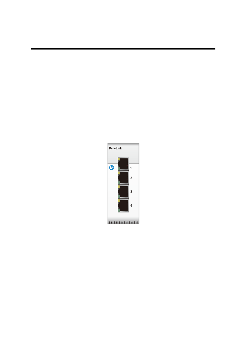
2.3 Data transmission
The Benelink module is connected with external devices via the serial ports (physical
interfaces are RJ45 connectors). You can simultaneously connect up to four external
devices via one BeneLink module. Parameters, alarm data from the external devices
can be output. For BeneVision N Series monitors, respiratory waveforms and loops
from the external devices can also be output. BeneVision N Series monitors can
output the parameter measurements, alarm limit settings, and alarm status to
external devices via the DIAP protocol (Datascope Improved ASCII Protocol).
2.4 Supported Devices
Please contact Mindray service personnel for the most recent information on the
supported devices.
2.4.1 Supported Anesthesia Machines
Brand Model ID for ID
adapter
Draeger Apollo 444FBBB1 Type C
Type of serial port
adapting cable
Fabius GS 4446BBBA Type C
Fabius Tiro 4446BBBA Type C
Perseus A500 4435BBCB None needed
GE Aestiva 7900/7100 4F37B0C9 Type D
Aespire 7900/7100 (for
BeneVision N Series only)
Aespire View (for
BeneVision N Series only)
Aisys 4F41B0BF Type D
Aisys CS2 (for BeneVision N
Series only)
2-2 BeneLink Module Operator’s Manual
4F37B0C9 Type D
4145bebb Type D
4F41B0BF Type D
Page 23

Brand Model ID for ID
adapter
Type of serial port
adapting cable
Avance 4F41B0BF Type D
MAQUET FLOW-i 4D46B2BA Type B
Mindray A7/A5/A4/A3 4D52B2AE None needed
2.4.2 Supported Ventilators
Brand Model ID for ID
adapter
Type of serial port
adapting cable
Carefusion Avea (for BeneVision N
5645a9bb Type E
Series only)
Vela 564CA9B4 Type E
Draeger Babylog 8000 4442BBBE Type B
Babylog 8000 plus 4442BBBE Type B
Evita 2 /Evita XL 4434BBCC Type B
Evita 2 dura 4434BBCC Type B
Evita 4 4434BBCC Type B
Infinity V500/Babylog
4456BBAA None needed
VN500
Savina 300 4441BBBF Type B
GE Carescape R860 4F52B0AE Type B
Engström(Carestation) 4F45B0BB Type B
Hamilton C1/C2/C3/T1 (C1 and T1 are
3270CD90 Type B
for BeneVision N Series
only)
G5 (Block Protocol) 3542CABE Type B
G5 (Polling Protocol) 3550CAB0 Type B
BeneLink Module Operator’s Manual 2-3
Page 24

Brand Model ID for ID
adapter
Type of serial port
adapting cable
Galileo (Polling Protocol) 4750B8B0 Type B
MAQUET SERVO-i/SERVO-s 4D53B2AD Type B
SERVO-U/SERVO-N 4d55B2AB Type B
Newport E360 4E50B1B0 Type B
Philips Respironics V60 5637A9C9
(VRPT)
5636A9CA
(SDNA)
Puritan
Bennett
PB840
(SNDF protocol)
PB840
5042AFBE None needed
5031AFCF None needed
(SNDA protocol)
PB980
5042AFBE Type C
(SNDF protocol)
PB980
5031AFCF Type C
(SNDA protocol)
ResMed VSIII (for Passport M series
5653A9AD Type C
only)
25 pin to 9 pin null
modem type cable
(male to female) +
Type B
2-4 BeneLink Module Operator’s Manual
Page 25

2.4.3 Supported tcGas Monitoring Devices
Brand Model ID for ID
adapter
Type of serial port
adapting cable
Biometer TCM40
TCM4 (for BeneVision N
Series only)
TCM Tosca/TCM CombiM
(for Passport M series only)
SenTec SenTec Digital Monitor 5354ACAC Type C
5443ABBD Type C
5443ABBD Type C
2.4.4 Supported Infusion System (For BeneVision N Series
Monitors only)
Brand Model ID for ID
adapter
B.Braun Perfusor Space 4250BDB0 Type F
Fresenius Agilia Injectomat 4650b9b0 Type G
Agilia Injectomat MC 4650b9b0 Type G
Agilia Injectomat TIVA 4650b9b0 Type G
Agilia Volumat 4650b9b0 Type G
Agilia Volumat MC 4650b9b0 Type G
Type of serial port
adapting cable
BeneLink Module Operator’s Manual 2-5
Page 26

2.4.5 Supported Other Devices
Brand/Device
Description
Model ID for ID
adapter
Type of serial port
adapting cable
Masimo/
pulse
CO-oximeter
Organon/
NMT
monitoring
device
Radical 7 (for BeneVision
N Series only)
TOF Watch SX® 5457ABA9 Type C
5241ADBF Type C (via Docking
Station)
USB to serial port
cable (via Root)
2.4.6 Connecting External Devices via DIAP Protocol (For
BeneVision N Series Monitors only)
The ID adapter can be configured to support the DIAP protocol. When the ID adapter
is connected to the BeneLink module, the third party device can obtain the
measurement numerics and alarm limit settings of the current patient through the
DIAP protocol.
See chapter 8 Connecting External Devices via DIAP Protocol (For BeneVision N
Series Monitors only) for details on configuring the ID adapter to support the DIAP
interface.
2-6 BeneLink Module Operator’s Manual
Page 27

2.5 Configuring the ID Adapter
To configure the ID adapter to work with your external device, follow this procedure:
1. Select [Update ID module]:
For BeneVision N Series monitor, select the [Main Menu] quick key →
from the [System] column select [Maintenance] → input the factory
maintenance password → select [Ok] → select the [Factory
Maintenance] tab → select the [Setup] tab → select [Update ID
module].
For Passport 12m/17m, select [Main Menu] → [Factory
Maintenance>>] → input the factory maintenance password →
[Update ID module].
2. Set [Benelink Module Port] and [ID].
The setting of [Benelink Module Port] shall be consistent with the
port the RJ45 connecting cable is connected to.
You must connect the RJ45 connecting cable to the selected port when
configuring the ID adapter. Otherwise, ID adapter configuration will
fail.
Set [ID] to configure a new ID to the ID adapter. Refer to Column “ID for
ID Adapter” in the tables above to obtain the ID information for each
external device.
CAUTION
ID adapter setup should only be conducted by Mindray authorized
personnel.
BeneLink Module Operator’s Manual 2-7
Page 28
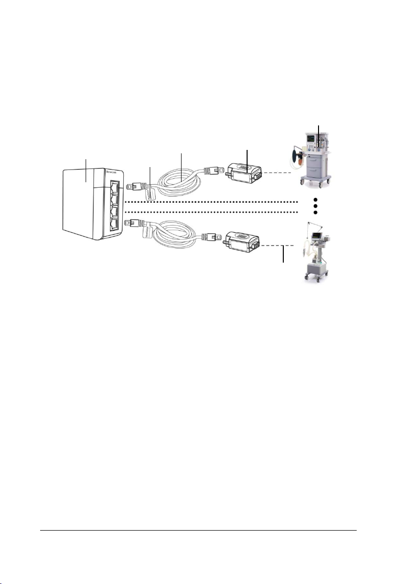
2.6 Connecting External Devices
(4)
(1)
(6)
(2)
The external devices are connected with the BeneLink module through an ID adapter,
which supports only its matching device. Please refer to the following procedure to
connect an external device:
(5)
(3)
(1) BeneLink module (2) Label
(3) RJ45 connecting cable
(5) External device (6) Serial port adapting cable (optional)
(4) ID adapter
ke sure that BeneLink module contains the device drivers which match the
1. Ma
devices you want to connect.
For BeneVision N Series monitor, to check the installed device drivers,
select the [Main Menu] quick key from the [System] column, select
[Maintenance] → input required password → select [Ok] → select the
[Version] tab, check [BeneLink Module Version]. If desired device
drivers are not installed, contact Mindray service to inquire about
solutions.
For Passport 12m/17m, to check the installed device drivers, contact
Mindray service.
2-8 BeneLink Module Operator’s Manual
Page 29

2. Insert the BeneLink module into the SMR or module rack.
3. Connect the ID adapter that matches the external device to the BeneLink
module with an RJ45 connecting cable.
4. Plug the ID adapter into the RS232 port on the external device. Some external
devices may have ports incompatible with the ID adapter. In this case, a serial
port adapting cable is required.
5. Adhere a device name label to the RJ45 connecting cable at the end close to the
BeneLink module. When the BeneLink module is connected to several external
devices, you can identify devices easily with these labels.
6. Switch on the external device.
After the external device is connected to the monitor, the indicators on both the ID
adapter and the BeneLink module illuminate to show that the monitor is successfully
communicating with the external device.
BeneLink Module Operator’s Manual 2-9
Page 30

2.7 Accessories
PN Description
115-007277-00 ID adapter
009-001767-00
009-001768-00
009-001769-00
009-002943-00
009-004613-00
009-008485-00
009-008624-00
047-004857-00 ID adapter label
047-004859-00 Network line label
009-001770-00 RJ45 connecting cable
Serial port adapting cable, Type A, 9-pin (male) to 9-pin
(female) crossover
Serial port adapting cable, Type B, 9-pin (male) to 9-pin
(male) straight-through
Serial port adapting cable, Type C, 9-pin (male) to 9-pin
(male) crossover
Serial port adapting cable, Type D, 9-pin (male) to 15-pin
(male)
Serial port adapting cable, Type E, 9-pin (male) to RJ45
connector
Serial port adapting cable, Type F, 9-pin (male) to 9-pin
(male), custom pin out
Serial port adapting cable, Type G, 9-pin (male) to 8-pin
(male)
2-10 BeneLink Module Operator’s Manual
Page 31

3 Integrating the Anesthesia Machine
Th
is chapter lists the parameters and alarms displayed on the monitor. However,
parameter and alarm information displayed on the external devices may be slightly
different.
NOTE
The units of parameters displayed on BeneVision N Series/Passport M
series monitor are controlled by the unit settings of the monitor and
may not be in the same unit as set on the external device.
3.1 Draeger Apollo
3.1.1 Output Signals—Parameters
Monitor output: parameters from Daeger Apollo anesthesia machine
Label Description Trend, record, print
Monitoring Parameters
PEEP Positive end-expiratory pressure Yes
Ppeak Peak pressure Yes
Pplat Plateau pressure Yes
Pmean Mean pressure Yes
VTi Inspired tidal volume Yes
MV Minute volume Yes
fspn Spontaneous respiratory rate Yes
Compl Compliance Yes
RRCO2 Respiratory rate of CO2 Yes
EtCO2 End-tidal carbon dioxide Yes
FiCO2 Fraction of inspired carbon dioxide Yes
BeneLink Module Operator’s Manual 3-1
Page 32

Monitor output: parameters from Daeger Apollo anesthesia machine
Label Description Trend, record, print
FiO2
Fractional concentration of O
gas
in inspired
2
Yes
EtO2 End-tidal O2 Yes
ΔO2
Difference between inspiratory and
expiratory O
2
No
Tapnea Apnea time No
FiN2O Inspired anesthetic agent Yes
FiIso Inspired anesthetic agent Yes
FiDes Inspired anesthetic agent Yes
FiEnf Inspired anesthetic agent Yes
FiSev Inspired anesthetic agent Yes
FiHal Inspired anesthetic agent Yes
EtN2O End-tidal anesthetic agent Yes
EtEnf End-tidal anesthetic agent Yes
EtDes End-tidal anesthetic agent Yes
EtIso End-tidal anesthetic agent Yes
EtSev End-tidal anesthetic agent Yes
EtHal End-tidal anesthetic agent Yes
FiAA Inspired anesthetic agent Yes
EtAA End-tidal anesthetic agent Yes
FiAA 2nd
2nd Insp. Agent Yes
EtAA 2nd 2nd Exp. Agent Yes
Insp. MAC Inspired minimum alveolar concentration No
Exp. MAC Expired minimum alveolar concentration No
HALLev Anesthetic agent consupmtion No
ENFLev Anesthetic agent consupmtion No
ISOLev Anesthetic agent consupmtion No
DESLev Anesthetic agent consupmtion No
3-2 BeneLink Module Operator’s Manual
Page 33

Monitor output: parameters from Daeger Apollo anesthesia machine
Label Description Trend, record, print
SEVLev Anesthetic agent consupmtion No
N2O Flow N2O flow No
Air Flow Air flow No
O2 Flow O2 flow No
SpO2
Arterial oxygen saturation from pulse
oximetry
Yes
PR Pulse rate Yes
VO2 Oxygen consumption Yes
VTe Expiratory tidal volume Yes
Setting Parameters
VTi Inspired tidal volume No
f Breath rate No
FreqMIN Minimum breath frequency No
TIP:TI
Tslope
Percentage of inspiratory plateau time in
inspiratory time
Time for the pressure to rise to target
pressure
No
No
Tinsp Time of inspiration No
Pinsp Pressure control level of inspiration No
Psupp Pressure support level No
Pmax Maximal breathing pressure No
F-Trigger Inspiratory trigger level (flow trigger) No
BeneLink Module Operator’s Manual 3-3
Page 34

3.1.2 Output Signals—Alarms
Monitor output: alarms from Daeger Apollo anesthesia machine
Priority
Physiological alarms
High
Me
dium
Label
Apnea
Volume Apnea > 2 min
Pressure Apnea
PAW High
PAW Low
FiO2 Low
CONT PRES
CO2 Apnea
No Pulse
PR Low
SpO2 Low
FiO2 Hi
gh
VTe Low
MV High
MV Low
PEEP High
EtCO2 High
EtCO2 Low
FiCO2 High
FiN2O High
EtHAL High
FiHal High
FiHal Low
EtENF High
FiENF High
FiENF Low
3-4 BeneLink Module Operator’s Manual
Page 35

Monitor output: alarms from Daeger Apollo anesthesia machine
Priority
Label
ISO High
Et
FiISO High
FiISO Low
EtSEV High
FiSEV High
Medium
FiSEV Low
EtDES High
FiDES High
FiDES Low
MAC Low
PR High
SpO2 High
Technical alarms
O2 Sup
ply Failure
No Fresh Gas
Circuit Occluded
VENT DISC
If the monitor shows the alarm [High Technical
alarms], the external device has one or more of the
Hi
gh
following alarms:
VENT ERR
High
Technical
Alarm
INT.TMP.HIGH
O2CYL.DISCON
O CYL
CHK N
2
NO N
O DELIV
2
NO AIR DELIV
FG-OVER?
BeneLink Module Operator’s Manual 3-5
Page 36

Monitor output: alarms from Daeger Apollo anesthesia machine
Priority
Hi
gh
Label
T. UNLOCK
VEN
AW-TEMP HIGH
O
NO N
2
NO O2 DELIV
Patient Circuit Leak
FRESH GAS?
CO2 Module abnormal
If the monitor shows the alarm [AG Module
abnormal], the external device has one or more of
Medium
AG
Module
abnormal
the following alarms:
MIXED AGENT
CO2/AGT ERR
O ERR
N
2
AGT ERR
2ND AGENT
CO2
Module
abnormal
If the monitor shows the alarm [CO2 Module
abnormal], the external device may have the
following alarms:
CO2 LINE BLK
3-6 BeneLink Module Operator’s Manual
Page 37

Monitor output: alarms from Daeger Apollo anesthesia machine
Priority
Label
If the monitor shows the alarm [Medium Technical
alarms], the external device has one or more of the
following alarms:
POWER FAIL
BATTERY LOW
O SUPPLY?
N
2
PRESSURE LIM
MIXER INOP
P MAX?
SAFETY O2 ON
FG FLOW LIM
Me
dium
Medium
Technical
Alarm
LOSS OF DATA
% O2 ERR
SET CANCELED
FG HIGH
FG ACTIVE
FG AIR SENS?
FG O2 SENS?
O SENS?
FG N
2
NO
AIR
NO O2 SUPPLY
If the monitor shows the alarm [SpO
abnormal], the external device has one or more of
the following alarms:
SPO2SEN DISC
SPO2 ALRM OF
Low
SpO2
Module
abnormal
SPO2 ERR
Module
2
BeneLink Module Operator’s Manual 3-7
Page 38

Monitor output: alarms from Daeger Apollo anesthesia machine
Priority
Label
If the monitor shows the alarm [Low Technical
alarms], the external device has one or more of the
following alarms:
FAN ERR
PWR SPLY ERR
PRESS ERR
VOL ERR
LO O2 SUPPLY
CHK O2 CYL
Low
Low
Technical
Alarm
O2 CYL OPEN
O CYLOPEN
N
2
AIR CYL OPEN
COM VENT ERR
APOLLO COM1?
APOLLO COM2?
O CYL .SENS?
N
2
AIR CYL SENS?
O2 CYL .SENS?
AIR CYL?
PRESS RELIEF
INSP VOL ERR
3.1.3 Output Signals – Waveforms (For BeneVision N Series
Monitors only)
The following waveforms from the external device can be output to the monitor:
Paw
Flow
CO2
3-8 BeneLink Module Operator’s Manual
Page 39

3.2 Draeger Fabius GS /Fabius Tiro
3.2.1 Output Signals – Parameters
Monitor output: parameters from Draeger Fabius GS/Fabius Tiro anesthesia machine
Label Description Trend, record, print
Monitoring Parameters
PEEP Positive end-expiratory pressure Yes
Ppeak Peak pressure Yes
Pplat Plateau pressure Yes
Pmean Mean pressure Yes
VTe Expiratory tidal volume Yes
MV Minute volume Yes
RRCO2 Respiratory rate of CO2 Yes
EtCO2 End-tidal carbon dioxide Yes
FiCO2 Fraction of inspired carbon dioxide Yes
FiO2
Fractional concentration of O
gas
FiN2O Fraction of inspired nitrous oxide Yes
EtN2O End-tidal N2O Yes
FiDes Inspired anesthetic agent Yes
FiSev Inspired anesthetic agent Yes
FiEnf Inspired anesthetic agent Yes
FiIso Inspired anesthetic agent Yes
FiHal Inspired anesthetic agent Yes
EtEnf End-tidal anesthetic agent Yes
EtDes End-tidal anesthetic agent Yes
EtIso End-tidal anesthetic agent Yes
EtSev End-tidal anesthetic agent Yes
EtHal End-tidal anesthetic agent Yes
FiAA Inspired anesthetic agent Yes
EtAA End-tidal anesthetic agent Yes
in inspired
2
Yes
BeneLink Module Operator’s Manual 3-9
Page 40

Monitor output: parameters from Draeger Fabius GS/Fabius Tiro anesthesia machine
Label Description Trend, record, print
N2O Flow N2O flow No
Air Flow Air flow No
O2 Flow O2 flow No
FiO2%
Fractional concentration of O
gas
in inspired
2
Yes
FiCO2% Fraction of inspired carbon dioxide Yes
EtCO2% End-tidal carbon dioxide Yes
Setting Parameters
VTi Inspired tidal volume No
f Breath rate No
I:E Inspiratory time: Expiratory time ratio No
TIP:TI
Percentage of inspiratory plateau time in
inspiratory time
No
Tinsp Time of inspiration No
Pinsp Pressure control level of inspiration No
Psupp Pressure support level No
Pmax Maximal breathing pressure No
F-Trigger
Inspiratory trigger
level (flow trigger)
No
Insp Flow Inspiration flow No
3-10 BeneLink Module Operator’s Manual
Page 41

3.2.2 Output Signals – Alarms
Monitor output: alarms from Draeger Fabius GS/Fabius Tiro anesthesia machine
Priority Label
Physiological alarms
Apnea
Volume Apnea > 2 min
Pressure Apnea
High
Medium
Low PRESSURE LIM
Technical alarms
FiO2 Low
Paw High
Paw Low
CONT PRES
FiO2 High
MV High
MV Low
PEEP High
PRESS EXP High
O2 Supply Failure
APL VALVE?
High
FRESH GAS?
High
Technical
alarms
Check
Expiration-Valve
If the monitor shows the alarm [High Technical
alarms], the external device has one or more of the
alarms: VENT ERR.
Check Fresh Gas Supply
Me
dium
Medium
Technical
alarms
If the monitor shows the alarm [Medium Technical
alarms], the external device has one or more of the
following alarms:
BeneLink Module Operator’s Manual 3-11
Page 42

Monitor output: alarms from Draeger Fabius GS/Fabius Tiro anesthesia machine
Priority Label
Me
Low
dium
Medium
Technical
alarms
Low
Technical
alarms
BATTERY LOW
PRESS ERR
VOL ERR
If the monitor shows the alarm [Low Technical
alarms], the external device has one or more of the
following alarms:
SPEAKER FAIL
POWER FAIL
CAL % O2 ?
% O2 ERR
TIME LIMITED
RS232COM ERR
PORT 1 ERROR
PORT 2 ERROR
THRESHOLD LO
3-12 BeneLink Module Operator’s Manual
Page 43

3.3 Draeger Perseus A500
3.3.1 Output Signals—Parameters
Monitor output: parameters from Draeger Perseus A500 anesthesia machine
Label Description Trend, record, print
Monitoring Parameters
ftot Total respiratory rate Yes
RAW Airway resistance Yes
VCO2 CO2 production No
HALLev Anesthetic agent consupmtion No
ENFLev Anesthetic agent consupmtion No
ISOLev Anesthetic agent consupmtion No
DESLev Anesthetic agent consupmtion No
SEVLev Anesthetic agent consupmtion No
VO2 Oxygen consumption Yes
Pmean Mean pressure Yes
Pplat Plateau pressure Yes
PEEP Positive end-expiratory pressure Yes
Ppeak Peak pressure Yes
Insp. MAC Inspired minimum alveolar concentration No
Exp. MAC Expired minimum alveolar concentration No
FiN2O Inspired anesthetic agent Yes
FiIso Inspired anesthetic agent Yes
FiDes Inspired anesthetic agent Yes
FiEnf Inspired anesthetic agent Yes
FiSev Inspired anesthetic agent Yes
FiHal Inspired anesthetic agent Yes
EtN2O End-tidal anesthetic agent Yes
EtEnf End-tidal anesthetic agent Yes
EtDes End-tidal anesthetic agent Yes
EtIso End-tidal anesthetic agent Yes
BeneLink Module Operator’s Manual 3-13
Page 44

Monitor output: parameters from Draeger Perseus A500 anesthesia machine
Label Description Trend, record, print
EtSev End-tidal anesthetic agent Yes
EtHal End-tidal anesthetic agent Yes
MVspn Spontaneous breathed minute volume Yes
MV Minute volume Yes
Tapnea Apnea time No
ΔO2
Difference between inspiratory and
expiratory O
2
No
RRCO2 Respiratory rate of CO2 Yes
FiCO2 Fraction of inspired carbon dioxide Yes
EtCO2 End-tidal carbon dioxide Yes
N2O Flow N2O flow No
Air Flow Air flow No
O2 Flow O2 flow No
FiAA Inspired anesthetic agent Yes
EtAA End-tidal anesthetic agent Yes
FiAA 2nd 2nd Insp. Agent Yes
EtAA 2nd 2nd Exp. Agent Yes
FiO2
Fractional concentration of O
gas
in inspired
2
Yes
EtO2 End-tidal O2 Yes
VTi Inspired tidal volume Yes
FiCO2% Fraction of inspired carbon dioxide Yes
EtCO2% End-tidal carbon dioxide Yes
ΔO2 %
Difference between inspiratory and
expiratory O
2
No
EtO2% End-tidal O2 Yes
FiO2%
Fractional concentration of O
gas
in inspired
2
Yes
3-14 BeneLink Module Operator’s Manual
Page 45

Monitor output: parameters from Draeger Perseus A500 anesthesia machine
Label Description Trend, record, print
Monitoring Parameters
VTi Inspired tidal volume No
f Breath rate No
PS above PEEP PS above PEEP No
Pmax Maximum airway pressure No
F-Trigger Inspiratory trigger level (flow trigger) No
TIP:TI
Tslope
Percentage of inspiratory plateau time in
inspiratory time
Time for the pressure to rise to target
pressure
No
No
FG Fresh gas flow No
Pinsp Pressure control level of inspiration No
PEEP Positive end-expiratory pressure No
3.3.2 Output Signals—Alarms
Monitor output: alarms from Draeger Perseus A500 anesthesia machine
Priority Label
Physiological alarms
Apnea
FiO2 Low
CO2 Apnea
High
Medium
Pressure Apnea
Paw High
Paw Low
CONT PRES
Hal High
Fi
FiEnf High
BeneLink Module Operator’s Manual 3-15
Page 46

Monitor output: alarms from Draeger Perseus A500 anesthesia machine
Priority Label
Fi
Iso High
FRESH GAS?
MV Low
FiSev High
FiDes High
EtCO2 Low
EtCO2 High
Me
dium
FiHal Low
FiEnf Low
FiIso Low
FiDes Low
FiSev Low
FiCO2 High
MV High
EXP-VALVE?
PEEP High
VTe High
MAC Low
FiN2O High
Technical alarms
ply Failure
O2 Sup
Hi
gh
NO Fresh Gas
VENT DISC
3-16 BeneLink Module Operator’s Manual
Page 47

Monitor output: alarms from Draeger Perseus A500 anesthesia machine
Priority Label
If the monitor shows the alarm [High Technical
alarms], the external device has one or more of the
following alarms:
VENT ERR
MIXER INOP
INT.TMP.HIGH
AIR PRESS HI
HI O2 SUPPLY
SYSTEM FAULT
O CYL.?
N
2
O
NO N
2
Hi
gh
gh
Hi
Technical
Alarm
NO OXYGEN
NO AIR
FG EXTERN?
ESH GAS?
FR
EXP VALVE?
If the monitor shows the alarm [Medium Technical
alarms], the external device has one or more of the
following alarms:
BATTERY LOW
% O2 ERR
Me
dium
Medium
Technical
Alarm
O SUPPLY ?
N
2
POWER FAIL
SAFETY O2 ON
FG LIMITED
LOSS OF DATA
SET.CANCELED
FG HIGH
FG ACTIVE
BeneLink Module Operator’s Manual 3-17
Page 48

Monitor output: alarms from Draeger Perseus A500 anesthesia machine
Priority Label
ABS.PRESENT?
HOSES MIXED?
WRONG HOSES?
AIR ENTRAIN
VENT PAUSE?
Me
dium
CO2
Module
abnormal
If the monitor shows the alarm [CO2 Module
abnormal], the external device has one or more of
the alarm: CO2 LINE BLK
If the monitor shows the alarm [AG Module
abnormal], the external device has one or more of
AG
Module
abnormal
the following alarms:
MIXED AGENT
CO2 AGT ERR
2nd AGENT
WATERTR.OLD?
If the monitor shows the alarm [Low Technical
alarms], the external device has one or more of the
following alarms:
RS232COM ERR
PRESS ERR
Low
Low
Technical
Alarm
WATER TRAP ?
VENT TEMP HI
VOL ERR
FAN ERR
O PRESS HI
N
2
O2 CYL. ?
VOLAT SUPPLY
CO2-LINE ?
PWR SPLY ERR
3-18 BeneLink Module Operator’s Manual
Page 49

Monitor output: alarms from Draeger Perseus A500 anesthesia machine
Priority Label
TIDAL VOL.?
INSP VOL ERR
OCYL.SENS?
N
2
Low
Low
Technical
Alarm
AIRCYL.SENS?
O2 CYL.SENS?
AIR CYL.?
PMIN REACHED
PRESS RELIEF
ABSORB. OLD?
ID-FUNC-INOP
HOSE OLD?
3.3.3 Output Signals - Waveforms (For BeneVision N Series
Monitors only)
The following waveforms from the external device can be output to the monitor:
Paw
Flow
CO2
O2
BeneLink Module Operator’s Manual 3-19
Page 50

3.4 GE Aespire 7900&7100/Aestiva 7900&7100
NOTE
Only the Benevision N sereis monitor supports integration with the GE
Aespire 7900&7100 anesthesia machine.
3.4.1 Output Signals – Parameters
Monitor output: parameters from GE Aespire 7900&7100/
Aestiva 7900&7100 anesthesi a machine
Label Description Trend, record, print
Monitoring Parameters
VTe Expiratory tidal volume Yes
MVe Expiratory minute volume Yes
O2% Oxygen concentration Yes
Ppeak Peak pressure Yes
Pplat Plateau pressure Yes
Pmean Mean pressure Yes
Pmin Minimum airway pressure No
ftot Total respiratory rate Yes
Setting Parameters
VT Tidal volume No
f Breath rate No
I:E
TIP:TI
PEEP Positive end-expiratory pressure No
Plimit Pressure limit level No
Pinsp Pressure control level of inspiration No
Percentage of inspiratory plateau time in
inspiratory time
Percentage of inspiratory plateau time in
inspiratory time
No
No
3-20 BeneLink Module Operator’s Manual
Page 51

3.4.2 Output Signals – Alarms
Monitor output: alarms from GE Aespire 7900&7100/Aestiva 7900&7100 anesthesia
machine
Priority Label
Physiological alarms
FiO2 Low
Paw High
High
Medium
Low Pressure limiting
Paw Low
High Paw Sustained
Volume Apnea > 2 min
FiO2 High
Sub-Atmospheric Paw
MV Low
MV High
VTe Low
VTe High
Volume Apnea
Technical alarms
No
Fresh Gas
O2 Supply Failure
If the monitor shows the alarm [High Technical
alarms], the external device has one or more of the
following alarms:
Hi
gh
gh
Hi
Technical
alarms
Pinspired Not Achieved
Inspiration Stopped
+15V SIB Out-of-Range
+15V Manifold Out-of-Range
Display Voltage Out-of-Range
Vaux_ref Out-of-Range
BeneLink Module Operator’s Manual 3-21
Page 52

Monitor output: alarms from GE Aespire 7900&7100/Aestiva 7900&7100 anesthesia
machine
Priority Label
Vext_ref Out-of-Range
A/D Converter Failure
CPU Failure
Memory (EEPROM) Failure
Hi
gh
High
Technical
alarms
Memory (flash) Failure
Memory (RAM) Failure
Memory (video) Failure
Bootup Memory Failure
Software Watchdog Failure
Hardware Watchdog Failure
Internal Clock Too Fast
Internal Clock Too Slow
CPU Internal Error
Control Settings Input Has Failed
If the monitor shows the alarm [Medium Technical
alarms], the external device has one or more of the
following alarms:
No Pressure Mode/PEEP
Inspiratory Overshoot
Me
Me
dium
dium
Technical
alarms
Manifold Pressure Sensor Failure
High Pressure Limit Reached (min sys)
Inspiratory Reverse Flow
Expiratory Reverse Flow
Check Flow Sensors
Flow Valve Failure
Gas Inlet Valve Failure
Bootup Gas Inlet Valve Failure
3-22 BeneLink Module Operator’s Manual
Page 53

Monitor output: alarms from GE Aespire 7900&7100/Aestiva 7900&7100 anesthesia
machine
Priority Label
Me
Low
dium
Me
dium
Technical
alarms
Battery in Use
Low
Technical
alarms
Memory (redundant storage) Fail
No Battery
Low Battery Charge
Low VE Limit Set.
If the monitor shows the alarm [Low Technical
alarms], the external device has one or more of the
following alarms:
Check O2 Sensor
O2 Calibration Error
PEEP Not Achieved
Vt Not Achieved
No Inspiratory Flow Sensor
No Expiratory Flow Sensor
Insp Vt/Vte Mismatch
Vdel Mismatch
Bellows Empty
+Vanalog Failure
-Vanalog Failure
Flow Sensor Cal Data Corrupt
Low Battery
Low Battery (shutdown)
Battery Voltage Out Of Range
Battery Current Out Of Range
Circuit Auxiliary
Auxiliary Breathing Circuit
Service Calibrations Due
BeneLink Module Operator’s Manual 3-23
Page 54

3.4.3 Output Signals - Waveforms (For BeneVision N Series
Monitors only)
The following waveforms from the external device can be output to the monitor:
Paw
Flow
3.5 GE Aespire View (for BeneVision N Series Monitors only)
3.5.1 Output Signals – Parameters
Monitor output: parameters from GE Aespire View anesthesia machine
Label Description Trend, record, print
Monitoring Parameters
VTe
MVe
ftot
O2%
Ppeak
Pplat
Pmean
Pmin
MVspn
fspn
VTi
MVi
3-24 BeneLink Module Operator’s Manual
Expiratory tidal volume Yes
Expiratory minute volume Yes
Total respiratory rate Yes
Oxygen concentration Yes
Peak pressure Yes
Plateau pressure Yes
Mean pressure Yes
Minimum airway pressure No
Spontaneous breathed minute volume Yes
Spontaneous respiratory rate
Inspired tidal volume Yes
Inspiratory minute volume Yes
Yes
Page 55

Monitor output: parameters from GE Aespire View anesthesia machine
Label Description Trend, record, print
PEEPtot
ATMP
O2 Flow
N2O Flow
Air Flow
Setting Parameters
VT
f
I:E
TIP:TI
PEEP
Plimit
Pinsp
Total PEEP No
Barometric pressure No
flow No
O
2
O flow No
N
2
Air flow
No
Tidal volume No
Breath rate No
Inspiratory time:Expiratory time ratio No
Percentage of inspiratory plateau time in
inspiratory time
No
Positive end-expiratory pressure No
Pressure limit level No
Pressure control level of inspiration No
Psupp
F-Trigger
Tinsp
Pressure support level
Inspiratory trigger level (flow trigger) No
Time of inspiration No
No
BeneLink Module Operator’s Manual 3-25
Page 56

3.5.2 Output Signals - Alarms
Mindray Patient Monitor
Priority Label
Paw High
High
Medium
Low Pressure Limiting
High
Medium
Paw Low
Volume Apnea > 2 min
Sub-Atmospheric Paw
MV Low
MV High
VTe Low
VTe High
Volume Apnea
No Fresh Gas
O2 Supply Failure
High Technical alarms
Patient Circuit Leak
Medium Technical alarms
Battery in Use
Low
Low Technical alarms
3.5.3 Output Signals – Waveforms
The following waveforms from the external device can be output to the monitor:
Paw
Flow
Volume
3-26 BeneLink Module Operator’s Manual
Page 57

3.5.4 Output Signals – Respiratory Loops
The following respiration loops from the external device can be output to the
monitor:
PV Loop
FV Loop
PF Loop
3.6 GE Aisys/ Aisys CS2/Avance
E
NOT
Only the Benevision N sereis monitor supports integration with the GE
Aisys CS2 anesthesia machine.
3.6.1 Output Signals – Parameters
Monitor output: parameters from GE Aisys/Aisys CS2/Avanc e anesthesi a machine
Label Description Trend, record, print
Monitoring Parameters
VTe Expiratory tidal volume Yes
MVe Expiratory minute volume Yes
ftot Total respiratory rate Yes
O2% Oxygen concentration Yes
Ppeak Peak pressure Yes
Pplat Plateau pressure Yes
Pmean Mean pressure Yes
Pmin Minimum airway pressure No
MVspn Spontaneous breathed minute volume Yes
fspn Spontaneous respiratory rate Yes
VTi Inspired tidal volume Yes
MVi Inspiratory mimute volume Yes
BeneLink Module Operator’s Manual 3-27
Page 58

Monitor output: parameters from GE Aisys/Aisys CS2/Avanc e anesthesi a machine
Label Description Trend, record, print
PEEPtot Total PEEP No
ATMP Barometric pressure No
O2 Flow O2 flow No
N2O Flow N2O flow No
Air Flow Air flow No
Monitoring Parameters
VT Tidal volume No
f Breath rate No
I:E Inspiratory time: Expiratory time ratio No
TIP:TI
Percentage of inspiratory plateau time in
inspiratory time
No
PEEP Positive end-expiratory pressure No
Plimit Pressure limit level No
Pinsp Pressure control level of inspiration No
Psupp Pressure support level No
F-Trigger
Inspiratory trigger
level (flow trigger)
No
Tinsp Time of inspiration No
3-28 BeneLink Module Operator’s Manual
Page 59

3.6.2 Output Signals – Alarms
Monitor output: alarms from GE Aisys/Aisys CS2/Avance anesthesia machine
Priority Label
Physiological alarms
Paw High
High
Me
dium
Low Pressure Limiting
Technical alarms
High
Medium
BeneLink Module Operator’s Manual 3-29
Paw Low
Volume Apnea > 2 min
Sub-Atmospheric Paw
MV Low
MV High
VTe Low
VTe High
Volume Apnea
No Fresh Gas
O2 Supply Failure
Circuit Occluded
High
Technical
alarms
If the monitor shows the alarm [High Technical
alarms], the external device has one or more of the
following alarms:
Other Priority Alarms
Patient Circuit Leak
If the monitor shows the alarm [Medium Technical
alarms], the external device has one or more of the
Medium
Technical
alarms
following alarms:
High Circuit O2
Low Circuit O2
No O2 Cell Sensor
No Pressure Cntrl/PEEP
Page 60

Monitor output: alarms from GE Aisys/Aisys CS2/Avance anesthesia machine
Priority Label
Inspiration Stopped
Inspiratory Reverse Flow
Expiratory Reverse Flow
Check Flow Sensors
No Air Pressure
Battery Failure
Battery in Use
If the monitor shows the alarm [Low Technical
alarms], the external device has one or more of the
Low
Low
Low
Technical
alarms
following alarms:
Replace O2 Cell
O2 Cell Calibration Error
Vt Not Achieved
No Inspiratory Flow Sensor
No Expiratory Flow Sensor
Dry or Replace Sensors
System Leak?
Unable to drive bellows
Memory (EEPROM) Failure
3-30 BeneLink Module Operator’s Manual
Page 61

3.6.3 Output Signals - Waveforms (For BeneVision N Series
Monitors only)
The following waveforms from the external device can be output to the monitor:
Paw
Flow
Volume
CO2
O2
AA
Hal
Des
Sev
Enf
Iso
3.7 MAQUET FLOW-i
3.7.1 Output Signals – Parameters
Monitor output: parameters from MAQUET FLOW-i an esthesia machine
Label Description Trend, record, print
Monitoring Parameters
PEEP Positive end-expiratory pressure Yes
Ppeak Peak pressure Yes
Pplat Plateau pressure Yes
Pmean Mean pressure Yes
VTi Inspired tidal volume Yes
MVe Expiratory minute volume Yes
MVi Inspiratory mimute volume Yes
BeneLink Module Operator’s Manual 3-31
Page 62

Monitor output: parameters from MAQUET FLOW-i an esthesia machine
Label Description Trend, record, print
ftot Total respiratory rate Yes
I:E Inspiratory time:Expiratory time ratio No
Exp Flow Expiratory flow No
Compl Compliance Yes
EtCO2 End-tidal carbon dioxide Yes
FiCO2 Fraction of inspired carbon dioxide Yes
FiO2
Fractional concentration of O
gas
in inspired
2
Yes
EtO2 End-tidal O2 Yes
FiN2O
EtN2O
Fraction of inspired nitrous oxide Yes
End-tidal N
O Yes
2
FiAA Inspired anesthetic agent Yes
EtAA End-tidal anesthetic agent Yes
FiAA 2nd 2nd Insp. Agent Yes
EtAA 2nd 2nd Exp. Agent Yes
MAC Minimum alveolar concentration Yes
PO2 Oxygen supply pressure No
O supply pressure No
PN2O
N
2
Pair Air supply pressure No
Duty cycle or ratio of inspiration time
Ti/Ttot
to total breathing cycle time (only during
No
spontaneous breathing)
FiO2%
Fractional concentration of O
gas
in inspired
2
Yes
EtO2% End-tidal O2 Yes
FiCO2% Fraction of inspired carbon dioxide Yes
EtCO2% End-tidal carbon dioxide Yes
VTe Expiratory tidal volume Yes
3-32 BeneLink Module Operator’s Manual
Page 63

Monitor output: parameters from MAQUET FLOW-i an esthesia machine
Label Description Trend, record, print
Setting Parameters
VT Tidal volume No
MV Minute volume No
f Breath rate No
I:E Inspiratory time: Expiratory time ratio No
Tslope
Time for the pressure to rise to target
pressure
No
Tinsp Time of inspiration No
PC above PEEP PC above PEEP No
PS above PEEP PS above PEEP No
P-Trigger
F-Trigger
Inspiratory trigger
level(pressure trigger)
Inspiratory trigger
level (flow trigger)
No
No
Insp Flow Inspiratory flow No
FG Fresh gas flow No
PEEP Positive end-expiratory pressure No
Rise Time% rise time% No
Tpause% Pause Time No
Tinsp% Time of inspiration No
Tpause s Pause Time No
BeneLink Module Operator’s Manual 3-33
Page 64

3.7.2 Output Signals – Alarms
Monitor output: alarms from MAQUET FLOW-i anesthesia machine
Priority Label
Physiological alarms
Apnea
High
Me
dium
Paw High
High Paw Sustained
MV High
MV Low
PEEP High
PEEP Low
EtCO2 High
EtCO2 Low
FiCO2 High
FiN2O High
EtIso High
EtIso Low
FiIso High
FiIso Low
EtSev High
EtSev Low
FiSev High
FiSev Low
EtDes High
EtDes Low
FiDes High
FiDes Low
EtO2 High
EtO2 Low
FiO2 High
3-34 BeneLink Module Operator’s Manual
Page 65

Monitor output: alarms from MAQUET FLOW-i anesthesia machine
Priority Label
Medium FiO2 Low
RR High
Low
Technical alarms
RR Low
Circuit Occluded
If the monitor shows the alarm [High Technical
alarms], the external device has one or more of the
following alarms:
Mixture of Anesthesia agents
High
High
Technical
alarms
Gas Supply
Cross contamination of anesthesic Agents
Vaporizer liquid level
battery alarm
patient Cassette remove
patient Cassette exchange
check tubing alarm
If the monitor shows the alarm [Medium Technical
alarms], the external device has one or more of the
Me
dium
Me
dium
Technical
alarms
following alarms:
Gas Analyzer water trap
Gas Analyzer water trap missing
internal communication failure
High continuous APL
Pressure alarm
Leakage alarm
Low Battery in Use
BeneLink Module Operator’s Manual 3-35
Page 66

3.8 Mindray A7/A5/A4/A3
NOTE
Only the Benevision N series monitor supports integration with the
Mindray A4 Anesthesia machine.
3.8.1 Output Signals – Parameters
Monitor output: parameters from Mindray A7/A5/A4/A3 anesthesia machine
Label Description Trend, record, print
Monitoring Parameters
I:E Inspiratory time: Expiratory time ratio No
fmand Mandatory breathing frequency Yes
fspn Spontaneous respiratory rate Yes
PEEP Positive end-expiratory pressure Yes
Ppeak Peak pressure Yes
Pplat Plateau pressure Yes
Pmean Mean pressure Yes
MVe Expiratory minute volume Yes
VTe Expiratory tidal volume Yes
RAW Airway resistance Yes
Compl Compliance Yes
N2O Flow N2O flow No
Air Flow Air flow No
O2 Flow O2 flow No
EtCO2 End-tidal carbon dioxide Yes
FiCO2 Fraction of inspired carbon dioxide Yes
FiN2O Fraction of inspired nitrous oxide Yes
EtN2O End-tidal N2O Yes
EtDes End-tidal anesthetic agent Yes
EtSev End-tidal anesthetic agent Yes
3-36 BeneLink Module Operator’s Manual
Page 67

Monitor output: parameters from Mindray A7/A5/A4/A3 anesthesia machine
Label Description Trend, record, print
EtEnf End-tidal anesthetic agent Yes
EtIso End-tidal anesthetic agent Yes
EtHal End-tidal anesthetic agent Yes
FiDes Inspired anesthetic agent Yes
FiSev Inspired anesthetic agent Yes
FiEnf Inspired anesthetic agent Yes
FiIso Inspired anesthetic agent Yes
FiHal Inspired anesthetic agent Yes
FiAA Inspired anesthetic agent Yes
EtAA End-tidal anesthetic agent Yes
MAC Minimum alveolar concentration Yes
BIS Bispectral index Yes
SQI Signal quality index Yes
SR Suppression ratio Yes
EMG Electromyograph Yes
SEF Spectral edge frequency Yes
TP Total power Yes
BC Burst count Yes
HALLev Anesthetic agent consupmtion
ENFLev Anesthetic agent consupmtion
ISOLev Anesthetic agent consupmtion
No
DESLev Anesthetic agent consupmtion
SEVLev Anesthetic agent consupmtion
ftot Total breath rate Yes
FiO2%
Fractional concentration of O2 in inspired
gas
Yes
EtO2% End-tidal O2 Yes
MV Spn Spontaneous minute volume Yes
BeneLink Module Operator’s Manual 3-37
Page 68

Monitor output: parameters from Mindray A7/A5/A4/A3 anesthesia machine
Label Description Trend, record, print
MV Leak
Setting Parameters
F-Trigger
Difference between the inspiratory and
expiratory minute volume
Inspiratory trigger
level (flow trigger)
No
No
VT Tidal volume No
f Breath rate No
PEEP Positive end-expiratory pressure No
Plimit Pressure limit level No
Pinsp Pressure control level of inspiration No
Psupp Pressure support level No
Tinsp Time of inspiration No
Tslope
Time for the pressure to rise to target
pressure
No
FreqMin Minimum breath frequency No
TIP:TI
Percentage of inspiratory plateau time in
inspiratory time
No
3-38 BeneLink Module Operator’s Manual
Page 69

3.8.2 Output Signals – Alarms
Monitor output: alarms from Mindray A7/A5/A4/A3 anesthesia machine
Priority Label
Physiological alarms
Apnea
Volume Apnea>2min
Paw High
High
dium
Me
Paw Low
FiO2 High
FiO2 Low
CO2 Apnea
MV Hi
gh
MV Low
BIS High
BIS Low
EtCO2 High
EtCO2 Low
FiCO2 High
EtN2O Low
EtN2O High
FiN2O Low
FiN2O High
EtHal Low
EtHal High
FiHal Low
FiHal High
EtEnf Low
EtEnf High
FiEnf Low
BeneLink Module Operator’s Manual 3-39
Page 70

Monitor output: alarms from Mindray A7/A5/A4/A3 anesthesia machine
Priority Label
FiEnf High
EtIso Low
EtIso High
FiIso Low
FiIso High
EtSev Low
EtSev High
FiSev Low
Me
FiSev High
dium
EtDes Low
EtDes High
FiDes Low
FiDes High
VTe High
VTe Low
EtO2 Low
EtO2 High
FiO2 High
FiCO2 Low
Low Pressure limiting
Technical alarms
ive Gas Pressure Low
Dr
No Fresh Gas
Sustained Airway Pressure
gh
Hi
O2 Supply Failure
High
Technic
al
If the monitor shows the alarm [High Technical alarms], the
external device has one or more of the following alarms:
Negative Pressure
3-40 BeneLink Module Operator’s Manual
Page 71

Monitor output: alarms from Mindray A7/A5/A4/A3 anesthesia machine
Priority Label
alarms Check Flow Sensors
O Ratio Error
O2-N
2
Flowmeter Comm Stop
Aux Control Module Comm Stop
Power System Comm Stop
System going DOWN,Battery depleted!
Power Board High Temp
Breathing System Not Mounted
Flowmeter Cal. Data Error 01/02
Flowmeter Hardware Malfunction 01/02/03/04/05/06/07
High
Ventilator Hardware Malfunction
01/02/03/04/05/06/07/08/09/10/11/12
Aux Control Module Comm Error
Power Voltage Abnormal
Power Voltage Too Low
Backup Flow Control Deployment Failure
Flowmeter Comm Error
Auxi Ctrl Module Hardware Error 01/02/03/04/05
Ventilator Comm Error
Ventilator Selftest Error
Power System Comm Error
Keyboard Init Error
RT Clock Need Reset
RT Clock Not Exist
Mechanical Ventilation Failure
Device Fault, Ventilate Manually
nsor Unconnected
Medium
O2 Se
Patient Circuit Leak
BeneLink Module Operator’s Manual 3-41
Page 72

Monitor output: alarms from Mindray A7/A5/A4/A3 anesthesia machine
Priority Label
If the monitor shows the alarm [Medium Technical
alarms], the external device has one or more of the
following alarms:
PEEP Valve Failure
Insp Valve Failure
ACGO 3-way Valve Failure
Replace O2 Sensor
Medium
Technical
alarms
Battery Undetected
IP Address Conflict
Pressure Monitoring Channel Failure
Ventilator System Comm Stop
CO2 Absorber Disconnected
Electronic Flow Control Error
Me
dium
Backup Flow Control Retraction Failure
Air Supply Failure
N2O not detected
Backup Flow Control Valves Open
Total Flow Sensor Self Test Time Out
Backup Flow Control Error
PEEP Safety Valve Failure
Insp Reverse Flow
Exp Reverse Flow
ACGO On
TVe Below Control Range
Key Error
O2 Flush Failure
3-42 BeneLink Module Operator’s Manual
Page 73

Monitor output: alarms from Mindray A7/A5/A4/A3 anesthesia machine
Priority Label
If the monitor shows the alarm [AG Module Abnormal],
the external device has one or more of the following
alarms:
AG Hardware Error
O2 Sensor Error
External AG Self Test Error
AG Hardware Malfunction
AG Init Error
AG No Watertrap
AG Watertrap Type Wrong
Medium
dule
AG Mo
Abnormal
AG Change Watertrap
AG Comm Stop
AG Airway Occluded
AG Comm Error
AG Data Limit Error
AG Zero Failed
AG Cal. Failed
AG Accuracy Error
O/CO2/Enf/Iso/Sev/Hal/Des Accuracy Unspecified
O2/N
2
Mixed anesthetic gas and MAC < 3
Mixed anesthetic gas and MAC >=3
EtCO2/FiCO2/EtN
O/FiN2O/EtHal/FiHal/EtEnf/FiEnf/EtIso/
2
FiIso/EtSev/FiSev/EtDes/FiDes/EtO2/FiO2 Over Range
Internal AG Error 01 02 03 04 05 06 07 08 09 10 11 12
If the monitor shows the alarm [BIS Module Abnormal],
BIS Module
abnormal
the external device has one or more of the following
alarms:
BIS Init Error
BeneLink Module Operator’s Manual 3-43
Page 74

Monitor output: alarms from Mindray A7/A5/A4/A3 anesthesia machine
Priority Label
BISx Disconnected
BIS Comm Error
BIS Over Range
BIS High Imped.
BIS Sensor Off
BIS DSC Error
BIS DSC Malf
Medium
BIS Module
abnormal
BIS No Cable
BIS No Sensor
BIS Wrong Sensor Type
BIS SQI<50%
BIS SQI<15%
BIS Sensor Expired
BIS Sensor Fault
BIS Sensor Too Many Uses
Disconnect/Reconnect BIS
BIS Self Test Error
Batte
ry in Use
O2 Sensor Unconnected
If the monitor shows the alarm [Low Technical alarms],
the external device has one or more of the following
Low
Low
Technical
alarms
alarms:
Flow Sensor Failure
Pinsp Not Achieved
Vt Not Achieved
Calibrate O2 Sensor
Internal N
O Flow Failure
2
Internal O2 Flow Failure
3-44 BeneLink Module Operator’s Manual
Page 75

Monitor output: alarms from Mindray A7/A5/A4/A3 anesthesia machine
Priority Label
Internal Air Flow Failure
Heating Module Failure
Automatic Ventilation Disabled
BIS Electrode Unconnected
BIS Electrode 1/2/3/4 Lead Off
BIS Electrode 1/2/3/4 High Imped.
N2O Flow Too High
O2 Flow Too High
Low
Low
Technical
alarms
Air Flow Too High
Flowmeter Zero Failed
Electronic ACGO Undetected
O2 Branch Flow Not Achieved
Balance Gas Branch Flow Not Achieved
Backup Flow Control is enabled
Flowmeter Comm Stop
Calibrate Flow Sensor
Calibrate PEEP Valve
TV Comp Disabled
TVe > TVi
3-way Valve Failure
Sensor Zero Failed
TV Delivery High
Flowmeter Zero Failed
Ventilator Init Error
BeneLink Module Operator’s Manual 3-45
Page 76

3.8.3 Output Signals - Waveforms (For BeneVision N Series
Monitors only)
The following waveforms from the external device can be output to the monitor:
Paw
Flow
Volume
CO2
O2
N2O
AA
Hal
Des
Sev
Enf
Iso
3-46 BeneLink Module Operator’s Manual
Page 77

4 Integrating the Ventilator
4.1 Carefusion Avea (For BeneVision N Series Patient
Monitor Only)
4.1.1 Output Signals - Parameters
Monitor output: parameters from Carefusion Avea Ventilator
Label Description Trend, record, print
Monitoring Parameters
Monitoring
Parameters
Dynamic compliance Yes
Cstat
O2%
I:E
Leak Comp
PEEP
Exp.Flow
Insp.Flow
Pmean
PO2
Ppeak
Pplat
ftot
BeneLink Module Operator’s Manual 4-1
Static compliance Yes
Oxygen concentration Yes
Inspiratory time: Expiratory time ratio No
Leak compensation
Positive end-expiratory pressure Yes
Expiratory flow No
Inspiratory flow No
Mean pressure Yes
Oxygen supply pressure No
Peak pressure Yes
Plateau pressure Yes
Total breath rate Yes
No
Page 78

Monitor output: parameters from Carefusion Avea Ventilator
Label Description Trend, record, print
fspn
Vdel
MVspn
WOB
VTi
VTe spn
VT/kg
VTe Mand
VTe
MVe
Tinsp
Texp
Ri
Spontaneous respiratory rate
Yes
Total volume of gas delivered No
Spontaneous breathed minute volume Yes
Work of breathing Yes
Inspired tidal volume Yes
Spontaneous expiratory tidal volume Yes
TVe/IBW No
Mandatory Expiratory tidal volume No
Expiratory tidal volume Yes
Expiratory minute volume Yes
Time of inspiration No
Expiratory time No
Inspiratory resistance Yes
RSBI
Pair
P0.1
PEEPi
PEEPe
Re
Rapid shallow breathing index
Air supply pressure No
100 ms occlusion pressure No
Intrinsic positive end-expiratory pressure No
Extrinsic positive end-expiratory pressure No
Expiratory resistance Yes
Yes
4-2 BeneLink Module Operator’s Manual
Page 79

Monitor output: parameters from Carefusion Avea Ventilator
Label Description Trend, record, print
fmand
NIF
Setting Parameters
O2%
Base Flow
Exp%
Peak Flow
Tpause
Phigh
Plow
PEEP
Psupp
f
Mandatory breathing frequency Yes
Negative inspiratory force No
Fractional concentration of O2 in inspired
gas
Yes
Base Flow No
Inspiration termination level No
Peak flow No
Apnea Time No
Upper pressure level No
Lower pressure level No
Positive end-expiratory pressure No
Pressure support level No
Breath rate No
Trise
Tinsp
Tlow
F-Trigger
P-Trigger
VT
Rise time No
Time of inspiration No
Time for the lower pressure level No
Inspiratory trigger level (flow trigger)
No
Inspiratory trigger level (pressure trigger) No
Tidal volume No
BeneLink Module Operator’s Manual 4-3
Page 80

Monitor output: parameters from Carefusion Avea Ventilator
Label Description Trend, record, print
Pinsp
Thigh
Ti Max
Pressure control level of inspiration No
Time for the upper pressure level No
Maximum inspiration time No
4.1.2 Output Signals - Alarms
Monitor output: parameters from Carefusion Avea Ventilator
Priority Label
Physiological alarms
Ppeak High
PEEP Low
MV Low
High
Medium
Technical alarms
MV High
FiO2 Low
FiO2 High
Ppeak Low
RR High
VTe Low
VTe Hi gh
High
High Technical
alarms
If the monitor shows the alarm [High
Technical alarms], the external device may
have the following alarms:
Vent Inop
Loss of Gas
Circuit Disconnect
4-4 BeneLink Module Operator’s Manual
Page 81

Monitor output: parameters from Carefusion Avea Ventilator
Priority Label
Ext High Ppeak
Safety Valve
CIRCUIT OCCLUSION
Apnea Interval
High
High Technical
alarms
Loss of O2
Loss of Air
Loss of Heliox
Low Battery
Loss of A/C
ILV Disconnect
If the monitor shows the alarm [Medium
Technical alarms], the external device may
Medium
Medium
Technical alarms
have the following alarms:
Invalid Gas ID
Fan Failure
Battery in Use
If the monitor shows the alarm [Low
Technical alarms], the external device may
Low
Low Technical
alarms
have the following alarms:
Insp Time Limit
I:
E Limit
Volume Limit
BeneLink Module Operator’s Manual 4-5
Page 82

4.1.3 Output Signals – Waveforms
The following waveforms from the external device can be output to the monitor:
Paw
Flow
Volume
4.2 Carefusion Vela
4.2.1 Output Signals – Parameters
Monitor output: parameters from Carefusion Vela Ventilator
Label Description Trend, record, print
Monitoring Parameters
PEEP Positive end-expiratory pressure Yes
Ppeak Peak pressure Yes
Pmean Mean pressure Yes
VTe Expiratory tidal volume Yes
VTi Inspired tidal volume Yes
VTe spn Spontaneous expiratory tidal volume Yes
MVspn Spontaneous breathed minute volume Yes
MVe Expiratory minute volume Yes
ftot Total breath rate Yes
fspn Spontaneous respiratory rate Yes
I:E Inspiratory time:Expiratory time ratio No
FiO2%
FiO2
Fractional concentration of O
gas
Fractional concentration of O
gas
Texp Expiratory time No
PO2 Oxygen supply pressure No
in inspired
2
in inspired
2
Yes
Yes
4-6 BeneLink Module Operator’s Manual
Page 83

Monitor output: parameters from Carefusion Vela Ventilator
Label Description Trend, record, print
EtCO2 End-tidal carbon dioxide Yes
RSBI Rapid shallow breathing index Yes
Setting Parameters
PEEP Positive end-expiratory pressure No
VT Tidal volume No
f Breath rate No
Base Flow Base Flow No
F-trigger
Inspiratory trigger
level (flow trigger)
No
Psupp Pressure support level No
Tinsp Time of inspiration No
Pinsp Pressure control level of inspiration No
Phigh Upper pressure level No
Plow Lower pressure level No
Thigh Time for the upper pressure level No
Tlow Time for the lower pressure level No
Exp% Inspiration termination level No
Peak Flow Peak flow No
Ti max Maximum inspiration time No
O2% Oxygen concentration No
Tpause Pressure control level of inspiration No
BeneLink Module Operator’s Manual 4-7
Page 84

4.2.2 Output Signals – Alarms
Monitor output: alarms from Carefusion Vela Ventilator
Priority Label
Physiological alarms
MV Low
Apnea
High
Medium
Technical alarms
High
dium
Me
PEEP High
Ppeak High
Ppeak Low
FiO2 Alarm
EtCO2 High
EtCO2 Low
RR High
O2 cell cal. Needed
O2 Supply Pressure Low
Circuit Disconnect
If the monitor shows the alarm [High Technical
alarms], the external device has one or more of the
High
Technical
alarms
following alarms:
LOW BATTERY
MOTOR FAULT
VENT INOP
H/W FAULT
If the monitor shows the alarm [Medium Technical
alarms], the external device has one or more of the
Medium
Technical
alarms
following alarms:
CHECK EVENTS
LOW CLOCK BATTERY
CO2 COMMS ERROR
4-8 BeneLink Module Operator’s Manual
Page 85

Monitor output: alarms from Carefusion Vela Ventilator
Priority Label
CO2 Out Of Range
CO2 Sensor Fault
CO2 Sensor Temp
CO2 Zero Reqd
FAN FAILURE
Medium
Medium
Technical
alarms
CO2 Check Adapter
DE FAULTS
O2 SENSOR FAILURE
Invalid EtCO2
O2 INLET HIGH
MED BATTERY
XDCR FA ULT
Battery in Use
If the monitor shows the alarm [Low Technical
Low
Low
Technical
alarms
alarms], the external device has one or more of the
following alarms:
INVALID SERIAL NUMBER
NO CAL DATA
BeneLink Module Operator’s Manual 4-9
Page 86

4.3 Draeger Babylog 8000 plus/Babylog 8000
4.3.1 Output Signals—Parameters
Monitor output: parameters from Draeger Babylog 8000 plus/Babylog 8000
Ventilator
Label Description Trend, record, print
Monitoring Parameters
Cdyn Dynamic compliance Yes
Rdyn Dynamic lung resistance Yes
Pmean Mean pressure Yes
PEEP Positive end-expiratory pressure Yes
Ppeak Peak pressure Yes
Vti Inspired tidal volume Yes
Leak Comp Leak compensation No
MV Minute volume Yes
ftot Total respiratory rate Yes
FiO2
FiO2%
Setting Parameters
O2% Oxygen concentration No
Tinsp Time of inspiration No
fSIMV Frequency of SIMV No
PEEP/CPAP PEEP/CPAP No
Tapnea Apnea tidal volume No
Pmax Maximum airway pressure No
f Breath rate No
VT Tidal volume No
I:E Inspiratory time:Expiratory time ratio No
Fractional concentration of O2 in inspired
gas
Fractional concentration of O2 in inspired
gas
Yes
Yes
4-10 BeneLink Module Operator’s Manual
Page 87

4.3.2 Output Signals—Technical Alarms
Monitor output: alarms from Draeger Babylog 8000 plus/Babylog 8000 Ventilator
Priority Label
If the monitor shows the alarm [Medium Technical
Medium
Medium
Technical
Alarm
alarms], the external device has one or more of the
following alarms:
VOL ERR
% O2 ERR
4.4 Draeger Babylog VN500
4.4.1 Output Signals—Parameters
Monitor output: parameters from Draeger Babylog VN500 Ventilator
Label Description Trend, record, print
Monitoring Parameters
Cdyn Dynamic compliance Ye s
Rdyn Dynamic lung resistance Yes
VCO2 CO2 production No
Pmin Minimum airway pressure No
Pmean Mean pressure Yes
PEEP Positive end-expiratory pressure Yes
fmand Mandatory breathing frequency Yes
Ppeak Peak pressure Yes
VTe spn Spontaneous expiratory tidal volume Yes
MVLEAK Leakage minute volume No
Leak Comp Leak compensation No
fspn Spontaneous respiratory rate Ye s
MV Minute volume Yes
RSBI Rapid shallow breathing index Yes
BeneLink Module Operator’s Manual 4-11
Page 88

Monitor output: parameters from Draeger Babylog VN500 Ventilator
△
Label Description Trend, record, print
ftot Total respiratory rate Ye s
EtCO2% End-tidal carbon dioxide Yes
EtCO2 End-tidal carbon dioxide Ye s
I:E Inspiratory time: Expiratory time ratio No
FiO2% Fractional concentration of O2 in inspired
gas
FiO2 Fractional concentration of O2 in inspired
gas
Yes
Yes
MVe Expiratory minute volume Yes
MVi Inspiratory mimute volume Yes
VTe Expiratory tidal volume Ye s
VTi Inspired tidal volume Yes
VT/kg TVe/IBW No
Setting Parameters
O2% Fractional concentration of O2 in inspired
gas
Yes
Flow Flow No
Tinsp Time of inspiration No
f Breath rate No
PEEP Positive end-expiratory pressure No
int.PEEP
Intermittent PEEP No
Plow Lower pressure level No
Phigh Upper pressure level No
Tlow Time for the lower pressure level No
Thigh Time for the upper pressure level No
TAp nea Apnea Time No
Psupp Pressure support level No
Pmax Maximal breathing pressure No
4-12 BeneLink Module Operator’s Manual
Page 89

Monitor output: parameters from Draeger Babylog VN500 Ventilator
Label Description Trend, record, print
F-Trigger Inspiratory trigger level (flow trigger) No
Trise Rise time No
FlowAssist Flow assist No
Vol Assist Volume assist No
fapnea Breath rate for apnea ventilation No
Pinsp Pressure control level of inspiration No
ATC Automatic Tube Compensation No
Tube ID Tub e ID No
Tdisconnect Delay time for "Airway pressure lower alarm
limit"
No
Ti max Maximum inspiration time No
Exp% Inspiration termination level No
VT Tidal volume No
VTapnea Apnea tidal volume No
I:E Inspiratory time: Expiratory time ratio No
4.4.2 Output Signals – Alarms
Monitor output: alarms from Draeger Babylog VN500 Ventilator
Priority Label
Physiological alarms
Paw High
Paw Low
High
BeneLink Module Operator’s Manual 4-13
MV High
MV Low
FiO2 High
VT Low
Page 90

Monitor output: alarms from Draeger Babylog VN500 Ventilator
Priority Label
Apnea Ventilation
Apnea
EtCO2 High
EtCO2 Low
Medium
PEEP High
PEEP Low
VOL INCONST
Technical alarms
Air Supply Pressure Low
O2 Supply Pressure Low
CLEAN CO2
Power Failure
Check Flow Sensors
EXP-VALVE?
Negative Airway Pressure
Neo Flow Sensor Error
gh
Hi
Circuit Disconnect
No O2 Pressure
Airway Obstructed?
the monitor shows the alarm [High Technical alarms],
If
the external device may have the following alarms:
CO2 NOT CAL
gh
Hi
Technical
Alarms
BATE RY ERR
SPEAKER FAIL
VENT ERR
VOL CAL
VOL ERR
AW TEMP INOP
4-14 BeneLink Module Operator’s Manual
Page 91

Monitor output: alarms from Draeger Babylog VN500 Ventilator
Priority Label
AIR PRESS HI
HI O2 SUPPLY
SYSTEM FAU LT
Hi
gh
High
Technical
Alarms
CO2 NOT CAL X
BATTER ERR X
COOLING X
LOSS OF DATA
HOSE ERR
EJECTOR INOP
MAP LOW
O2 Err
PRESS_ERR
AW_TEM_SENS
INT_TEMP_HI
If the monitor shows the alarm [Medium Technical
alarms], the external device may have the following
alarms:
Me
dium
Medium
Technical
Alarms
GAS FAILURE
NO AIR
AMB_PRESS
BATT LOW
CHECK_EVITA
NEBULIZ OF
VT LIMITED
Battery In use
Low
Low
Technical
Alarms
If the monitor shows the alarm [Low Technical
alarms], the external device may have the following
alarms:
BeneLink Module Operator’s Manual 4-15
Page 92

Monitor output: alarms from Draeger Babylog VN500 Ventilator
Priority Label
Low
Low
Technical
Alarms
CO2 measurement failed
CO2 sensor ?
Plow>high limit
Plow<low limit
4.5 Draeger Evita 2
4.5.1 Output Signals – Parameters
Monitor output: parameters from Draeger Evita 2 Ventilator
Label Description Trend, record, print
Monitoring Parameters
O2% Oxygen concentration No
PEEP Positive end-expiratory pressure Yes
Ppeak Peak pressure Yes
Pplat Plateau pressure Yes
Pmean Mean pressure Yes
VTe Expiratory tidal volume Yes
MV Minute volume Yes
MVspn Spontaneous breathed minute volume Yes
ftot Total respiratory rate Yes
fspn Spontaneous breathing frequency Yes
FiO2
Fractional concentration of O
gas
Rdyn Dynamic lung resistance Yes
Cdyn Dynamic compliance Yes
Pmin Minimum airway pressure No
Vtrap Trapped volume No
T Inspiratory breathing gas temperature No
in inspired
2
Yes
4-16 BeneLink Module Operator’s Manual
Page 93

Monitor output: parameters from Draeger Evita 2 Ventilator
Label Description Trend, record, print
P0.1 100 ms occlusion pressure No
PEEPi Intrinsic positive end-expiratory pressure No
EtCO2 End-tidal carbon dioxide Yes
Vds Dead space No
VCO2 CO2 production No
EtCO2% End-tidal carbon dioxide Yes
FiO2%
Setting Parameters
Fractional concentration of O
gas
in inspired
2
Yes
O2% Oxygen concentration No
PEEP Positive end-expiratory pressure No
VT Tidal volume No
fSIMV Frequency of SIMV No
I:E Inspiratory time:Expiratory time ratio No
△int.PEEP
F-Trigger
P-Trigger
Intermittent PEEP No
Inspiratory trigger
level (flow trigger)
Inspiratory trigger
level (pressure trigger)
No
No
Phigh Upper pressure level No
Plow Lower pressure level No
Thigh Time for the upper pressure level No
Tlow Time for the lower pressure level No
Pmax Maximum airway pressure No
Flow Flow No
Tapnea Apnea Time No
ASB ramp ASB ramp No
PASB Assisted spontaneous breathing No
BeneLink Module Operator’s Manual 4-17
Page 94

4.5.2 Output Signals – Alarms
Monitor output: alarms from Draeger Evita 2 Ventilator
Priority Label
Physiological alarms
Paw High
Paw Low
MV High
MV Low
High
Medium
Apnea
FiO2 High
FiO2 Low
AW-TEMP HIGH
PEEP High
ASB>4s
EtCO2 High
EtCO2 Low
VOL INCONST
RR High
Technical alarms
Air Supply Pressure Low
Check Flow Sensors
Airway Obstructed
CLEAN CO2
High
EXP-VALVE? /O2 Supply Pressure Low
If the monitor shows the alarm [High Technical
Hi
gh
Technical
alarms
alarms], the external device has one or more of the
following alarms:
VOL ERR
PRESS ERR
AW-TEMP INOP
4-18 BeneLink Module Operator’s Manual
Page 95

Monitor output: alarms from Draeger Evita 2 Ventilator
Priority Label
Physiological alarms
AW-TEMP SENS
CO2 NOT CAL
High
High
Technical
alarms
% O2 ERR
EVITA ERR
COOLING INOP
CYCLE FAILED
COOLING INOP ADVISORY
If the monitor shows the alarm [Low Technical
alarms], the external device has one or more of the
following alarms:
Low
Low
Technical
alarms
CO2 ERR
CO2 SENS?
MIXER INOP
SYNCHRO INOP
MIXER INOP ADV
4.6 Draeger Evita2 dura/Evita 4/Evita XL
4.6.1 Output Signals – Parameters
Monitor output: parameters from Draeger Evita2 dura/Evita 4/Evita XL Ventilator
Label Description Trend, record, print
Monitoring Parameters
O2% Oxygen concentration No
PEEP Positive end-expiratory pressure Yes
Ppeak Peak pressure Yes
Pplat Plateau pressure Yes
Pmean Mean pressure Yes
BeneLink Module Operator’s Manual 4-19
Page 96

Monitor output: parameters from Draeger Evita2 dura/Evita 4/Evita XL Ventilator
Label Description Trend, record, print
VTe Expiratory tidal volume Yes
MV Minute volume Yes
MVspn Spontaneous breathed minute volume Yes
ftot Total respiratory rate Yes
fspn Spontaneous breathing frequency Yes
FiO2
Fractional concentration of O
gas
in inspired
2
Yes
Rdyn Dynamic lung resistance Yes
Cdyn Dynamic compliance Yes
RSBI Rapid shallow breathing index Yes
Pmin Minimum airway pressure No
Vtrap Trapped Volume No
T Inspiratory breathing gas temperature No
NIF Negative inspiratory force No
P0.1 100 ms occlusion pressure No
PEEPi Intrinsic positive end-expiratory pressure No
EtCO2 End-tidal carbon dioxide Yes
Vds Dead space No
VCO2 CO2 production No
PR Pulse rate Yes
SpO2
Arterial oxygen saturation from pulse
oximetry
Yes
EtCO2% End-tidal carbon dioxide Yes
FiO2%
Setting Parameters
Fractional concentration of O
gas
in inspired
2
Yes
O2% Oxygen concentration No
PEEP Positive end-expiratory pressure No
4-20 BeneLink Module Operator’s Manual
Page 97

Monitor output: parameters from Draeger Evita2 dura/Evita 4/Evita XL Ventilator
Label Description Trend, record, print
VT Tidal volume No
f Breath rate No
I:E Inspiratory time: Expiratory time ratio No
△int.PEEP
F-Trigger
Intermittent PEEP No
Inspiratory trigger
level (flow trigger)
No
Phigh Upper pressure level No
Plow Lower pressure level No
Thigh Time for the upper pressure level No
Tlow Time for the lower pressure level No
Pmax Maximum airway pressure No
Tinsp Time of inspiration No
Flow Flow No
Tapnea Apnea time No
ASB ramp ASB ramp No
PASB Assisted spontaneous breathing No
FlowAssist Flow assist No
Vol.Assist Volume assist No
Tdisconnect
Delay time for "Airway pressure lower alarm
limit"
No
BeneLink Module Operator’s Manual 4-21
Page 98

4.6.2 Output Signals – Alarms
Monitor output: alarms from Draeger Evita2 duraEvita 4/Evita XL Ventilator
Priority Label
Physiological alarms
Paw High
Paw Low
MV High
MV Low
Apnea
FiO2 High
FiO2 Low
High
Medium
Low
AW-TEMP HIGH
PEEP High
ASB>4s
No Pulse
PR Low
SpO2 Low
PR High
SpO2 High
VTe High
EtCO2 High
EtCO2 Low
VOL INCONST
RR High
ASB > 1.5s
PPS-TI > 1.5s
ASB > Tinsp
Technical alarms
4-22 BeneLink Module Operator’s Manual
Page 99

Monitor output: alarms from Draeger Evita2 duraEvita 4/Evita XL Ventilator
Priority Label
Ai
r Supply Pressure Low
O2 Supply Pressure Low
Airway Obstructed?
High
Check Flow Sensors
CLEAN CO2
Check Expiration-Valve
If the monitor shows the alarm [High Technical
alarms], the external device has one or more of the
following alarms:
VOL ERR
PRESS ERR
AW-TEMP INOP
EVITA ERR
High
CYCLE FAILED
N-VOL ERR
High
Technical
alarms
NEO FLOW ?
CO2 ZERO CAL
SPO2 SEN DISC
SPO2 ERR
BATTERY ERR E VITA4
FAN ERR EVITA 4
AIR PRESS HI E VITA4
HI O2 SUPPLY E VITA 4
LO SS OF DATA
REM .PAD-ERR
PEEP V ERR
CO2 NOT CAL
LO O2 SUPPLY EV ITA4
BeneLink Module Operator’s Manual 4-23
Page 100

Monitor output: alarms from Draeger Evita2 duraEvita 4/Evita XL Ventilator
Priority Label
If the monitor shows the alarm [Medium Technical
alarms], the external device has one or more of the
following alarms:
Medium
Low
Medium
Technical
alarms
Battery in Use
Low
Technical
alarms
BAT T. < 2M IN
CHECK EVITA
EVI TA STDBY
AMB PRESS ?
NEBULIZ OFF
ERR MULTIPCB
If the monitor shows the alarm [Low Technical
alarms], the external device has one or more of the
following alarms:
CO2 ERR
CO2 SENSOR ?
MIXER INOP
SYNCHRO INOP
INSPHOLD END
EXSPHOLD END
4.6.3 Output Signals - Waveforms (For BeneVision N Series
Monitors only)
The following waveforms from the external device can be output to the monitor:
Paw
Flow
Volume
CO2
4-24 BeneLink Module Operator’s Manual
 Loading...