

Page 1

BeneHeart D3
Defibrillator/Monitor
Operator’s Manual
Page 2

Page 3

I
© 2010 - 2013 Shenzhen Mindray Bio-Medical Electronics Co., Ltd. All rights reserved.
For this Operator’s Manual, the issue date is 2013-09.
Page 4

II
Intellectual Property Statement
SHENZHEN MINDRAY BIO-MEDICAL ELECTRONICS CO., LTD. (hereinafter called Mindray) owns the intellectual property
rights to this Mindray product and this manual. This manual may refer to information protected by copyright or
patents and does not convey any license under the patent rights or copyright of Mindray, or of others.
Mindray intends to maintain the contents of this manual as confidential information. Disclosure of the information in
this manual in any manner whatsoever without the written permission of Mindray is strictly forbidden.
Release, amendment, reproduction, distribution, rental, adaptation, translation or any other derivative work of this
manual in any manner whatsoever without the written permission of Mindray is strictly forbidden.
, , and are the trademarks, registered or otherwise, of
Mindray in China and other countries. All other trademarks that appear in this manual are used only for informational
or editorial purposes. They are the property of their respective owners.
Page 5

III
Responsibility on the Manufacturer Party
Contents of this manual are subject to change without prior notice.
All information contained in this manual is believed to be correct. Mindray shall not be liable for errors contained
herein or for incidental or consequential damages in connection with the furnishing, performance, or use of this
manual.
Mindray is responsible for the effects on safety, reliability and performance of this product, only if:
all installation operations, expansions, changes, modifications and repairs of this product are conducted by
Mindray authorized personnel;
the electrical installation of the relevant room complies with the applicable national and local requirements;and
the product is used in accordance with the instructions for use.
WARNING
z
This equipment must be operated by skilled/trained clinical professionals.
z
It is important for the hospital or organization that employs this equipment to carry out a reasonable
service/maintenance plan. Neglect of this may result in machine breakdown or personal injury.
Page 6

IV
Warranty
THIS WARRANTY IS EXCLUSIVE AND IS IN LIEU OF ALL OTHER WARRANTIES, EXPRESSED OR IMPLIED, INCLUDING
WARRANTIES OF MERCHANTABILITY OR FITNESS FOR ANY PARTICULAR PURPOSE.
Exemptions
Mindray's obligation or liability under this warranty does not include any transportation or other charges or liability
for direct, indirect or consequential damages or delay resulting from the improper use or application of the product or
the use of parts or accessories not approved by Mindray or repairs by people other than Mindray authorized
personnel.
This warranty shall not extend to:
Malfunction or damage caused by improper use or man-made failure.
Malfunction or damage caused by unstable or out-of-range power input.
Malfunction or damage caused by force majeure such as fire and earthquake.
Malfunction or damage caused by improper operation or repair by unqualified orunauthorized service people.
Malfunction of the instrument or part whose serial number is not legible enough.
Others not caused by instrument or part itself.
Company Contact
Manufacturer: Shenzhen Mindray Bio-Medical Electronics Co., Ltd.
Address: Mindray Building,Keji 12th Road South,Hi-tech industrial
park,Nanshan,Shenzhen 518057,P.R.China
Website: www.mindray.com
E-mail Address: service@mindray.com.cn
Tel: +86 755 81888998
Fax: +86 755 26582680
EC-Representative: Shanghai International Holding Corp. GmbH (Europe)
Address: Eiffestraβe 80, 20537 Hamburg, Germany
Tel: 0049-40-2513175
Fax: 0049-40-255726
Page 7

V
Preface
Manual Purpose
This manual contains the instructions necessary to operate the product safely and in accordance with its function and
intended use. Observance of this manual is a prerequisite for proper product performance and correct operation and
ensures patient and operator safety.
This manual is based on the maximum configuration and therefore some contents may not apply to your product. If
you have any question, please contact us.
This manual is an integral part of the product. It should always be kept close to the equipment so that it can be
obtained conveniently when needed.
Intended Audience
This manual is geared for clinical professionals who are expected to have a working knowledge of medical procedures,
practices and terminology as required for monitoring of critically ill patients.
Illustrations
All illustrations in this manual serve as examples only. They may not necessarily reflect the setup or data displayed on
your equipment.
Conventions
Italic text is used in this manual to quote the referenced chapters or sections.
[ ] is used to enclose screen texts.
→ is used to indicate operational procedures.
Page 8

VI
FOR YOUR NOTES
Page 9

1
Contents
1 Safety............................................................................................................................................................................ 1-1
1.1 Safety Information.............................................................................................................................................................................................1-1
1.1.1 Dangers ...................................................................................................................................................................................................1-2
1.1.2 Warnings .................................................................................................................................................................................................1-2
1.1.3 Cautions ..................................................................................................................................................................................................1-3
1.1.4 Notes ........................................................................................................................................................................................................1-3
1.2 Equipment Symbols..........................................................................................................................................................................................1-4
2 The Basics ..................................................................................................................................................................... 2-1
2.1 Overview...............................................................................................................................................................................................................2-1
2.2 Intended Use .......................................................................................................................................................................................................2-1
2.2.1 AED............................................................................................................................................................................................................2-2
2.2.2 Manual Defibrillation..........................................................................................................................................................................2-2
2.2.3 Noninvasive Pacing.............................................................................................................................................................................2-2
2.2.4 ECG............................................................................................................................................................................................................2-2
2.2.5 Resp ..........................................................................................................................................................................................................2-2
2.2.6 SpO2..........................................................................................................................................................................................................2-2
2.2.7 NIBP...........................................................................................................................................................................................................2-2
2.3 Main Unit ..............................................................................................................................................................................................................2-3
2.3.1 Front View...............................................................................................................................................................................................2-3
2.3.2 Side View.................................................................................................................................................................................................2-8
2.3.3 Rear View.................................................................................................................................................................................................2-9
2.3.4 External Paddles................................................................................................................................................................................ 2-10
2.4 Display Views.................................................................................................................................................................................................... 2-11
3 Basic Operations and Settings.................................................................................................................................... 3-1
3.1 Installation............................................................................................................................................................................................................3-1
3.1.1 Unpacking and Checking .................................................................................................................................................................3-1
3.1.2 Environmental Requirements .........................................................................................................................................................3-2
3.2 Basic Operation ..................................................................................................................................................................................................3-2
3.2.1 Turning Power On................................................................................................................................................................................3-2
3.2.2 Starting Monitoring or Therapy......................................................................................................................................................3-2
3.2.3 Disconnecting from Power...............................................................................................................................................................3-3
3.2.4 Auto Restoring to Last Configuration...........................................................................................................................................3-3
3.3 Using the Main Menu.......................................................................................................................................................................................3-3
3.4 Changing General Settings ............................................................................................................................................................................3-3
3.4.1 Setting the Date and Time................................................................................................................................................................3-3
3.4.2 Adjusting the Screen Brightness....................................................................................................................................................3-4
3.4.3 Changing Key Volume........................................................................................................................................................................3-4
3.4.4 Selecting High Contrast Mode........................................................................................................................................................3-4
Page 10

2
4 Managing Patients....................................................................................................................................................... 4-1
4.1 Overview .............................................................................................................................................................................................................. 4-1
4.2 Editing Patient Information........................................................................................................................................................................... 4-1
5 Alarms........................................................................................................................................................................... 5-1
5.1 Alarm Categories ............................................................................................................................................................................................... 5-1
5.2 Alarm Levels ........................................................................................................................................................................................................5-2
5.3 Alarm Indicators................................................................................................................................................................................................. 5-2
5.3.1 Alarm Lamps .........................................................................................................................................................................................5-2
5.3.2 Audible Alarms..................................................................................................................................................................................... 5-3
5.3.3 Alarm Message ..................................................................................................................................................................................... 5-3
5.3.4 Flashing Numeric................................................................................................................................................................................. 5-3
5.3.5 Alarm Status Symbols........................................................................................................................................................................ 5-3
5.4 Alarm Tone Configuration.............................................................................................................................................................................. 5-4
5.4.1 Changing the Alarm Volume........................................................................................................................................................... 5-4
5.4.2 Setting the Interval between Alarm Sounds .............................................................................................................................5-4
5.5 Understanding the Alarm Setup Menu..................................................................................................................................................... 5-4
5.5.1 Setting Alarm Properties for All Parameters.............................................................................................................................. 5-5
5.5.2 Adjusting Alarm Limits Automatically......................................................................................................................................... 5-6
5.6 Pausing Alarms................................................................................................................................................................................................... 5-7
5.7 Switching Alarms Off ....................................................................................................................................................................................... 5-7
5.8 Pausing Alarm Sounds..................................................................................................................................................................................... 5-8
5.9 Switching Off Alarm Sounds .........................................................................................................................................................................5-8
5.10 Reminder Tones...............................................................................................................................................................................................5-8
5.11 Latching Alarms............................................................................................................................................................................................... 5-9
5.12 Clearing Technical Alarms............................................................................................................................................................................ 5-9
5.13 When an Alarm Occurs................................................................................................................................................................................5-10
6 Monitoring ECG............................................................................................................................................................ 6-1
6.1 Overview .............................................................................................................................................................................................................. 6-1
6.2 Safety .....................................................................................................................................................................................................................6-1
6.3 Monitoring View ................................................................................................................................................................................................6-2
6.4 Preparing to Monitor ECG ..............................................................................................................................................................................6-2
6.4.1 ECG Monitoring with Electrodes.................................................................................................................................................... 6-2
6.4.2 ECG Monitoring with Paddles/Pads.............................................................................................................................................. 6-4
6.4.3 Checking Paced Status ...................................................................................................................................................................... 6-5
6.5 ECG Display.......................................................................................................................................................................................................... 6-5
6.6 Changing ECG Settings ...................................................................................................................................................................................6-6
6.6.1 Changing Lead Settings.................................................................................................................................................................... 6-6
6.6.2 Changing ECG Wave Settings..........................................................................................................................................................6-7
6.6.3 Switching the Notch Filter On or Off............................................................................................................................................ 6-7
6.6.4 Adjusting Heartbeat Volume...........................................................................................................................................................6-8
6.7 Arrhythmia Analysis.......................................................................................................................................................................................... 6-8
6.7.1 Understanding the Arrhythmia Events........................................................................................................................................6-8
6.7.2 Switching Arrhythmia Analysis On and Off ...............................................................................................................................6-9
6.7.3 Changing Arrhythmia Alarm Settings........................................................................................................................................6-10
Page 11

3
6.7.4 Changing Arrhythmia Threshold Settings............................................................................................................................... 6-10
6.7.5 Initiating Arrhythmia Relearning Manually............................................................................................................................. 6-11
6.7.6 Automatic Arrhythmia Relearn.................................................................................................................................................... 6-11
6.8 Calibrating ECG................................................................................................................................................................................................ 6-11
7 AED ............................................................................................................................................................................... 7-1
7.1 Overview...............................................................................................................................................................................................................7-1
7.2 Safety......................................................................................................................................................................................................................7-1
7.3 AED View...............................................................................................................................................................................................................7-2
7.4 AED Procedure....................................................................................................................................................................................................7-3
7.5 Shock Advised.....................................................................................................................................................................................................7-4
7.6 No Shock Advised (NSA)..................................................................................................................................................................................7-4
7.7 CPR ..........................................................................................................................................................................................................................7-5
7.7.1 CPR Metronome ...................................................................................................................................................................................7-5
7.8 AED Sound Recording......................................................................................................................................................................................7-6
7.9 AED Setup.............................................................................................................................................................................................................7-6
8 Manual Defibrillation .................................................................................................................................................. 8-1
8.1 Overview...............................................................................................................................................................................................................8-1
8.2 Safety......................................................................................................................................................................................................................8-1
8.3 Manual Defibrillation View.............................................................................................................................................................................8-3
8.4 Manual Defibrillation Procedure..................................................................................................................................................................8-3
8.4.1 Using Pediatric Paddles.....................................................................................................................................................................8-5
8.4.2 Using Internal Paddles .......................................................................................................................................................................8-5
8.5 Synchronized Cardioversion..........................................................................................................................................................................8-6
8.5.1 Performing Synchronized Cardioversion....................................................................................................................................8-7
8.5.2 Delivering Additional Synchronized Shocks..............................................................................................................................8-7
8.5.3 Disabling the Sync Function............................................................................................................................................................8-7
8.6 Remote Synchronized Cardioversion.........................................................................................................................................................8-8
8.7 Contact Impedance Indicator .......................................................................................................................................................................8-9
9 Noninvasive Pacing ..................................................................................................................................................... 9-1
9.1 Overview...............................................................................................................................................................................................................9-1
9.2 Safety......................................................................................................................................................................................................................9-1
9.3 Pacing View..........................................................................................................................................................................................................9-2
9.4 Demand Mode versus Fixed Mode..............................................................................................................................................................9-3
9.5 Preparing for Pacing.........................................................................................................................................................................................9-3
9.5.1 Demand Mode Pacing .......................................................................................................................................................................9-4
9.5.2 Fixed Mode Pacing..............................................................................................................................................................................9-5
10 Monitoring Resp ......................................................................................................................................................10-1
10.1 Overview ......................................................................................................................................................................................................... 10-1
10.2 Safety ................................................................................................................................................................................................................10-1
10.3 Resp View ........................................................................................................................................................................................................ 10-1
10.4 Placing Resp Electrodes .............................................................................................................................................................................10-2
10.4.1 Optimizing Lead Placement for Resp...................................................................................................................................... 10-3
Page 12

4
10.4.2 Changing Resp Wave Settings....................................................................................................................................................10-3
11 Monitoring PR.......................................................................................................................................................... 11-1
11.1 Overview ..........................................................................................................................................................................................................11-1
11.2 Adjusting Pulse Tone Volume...................................................................................................................................................................11-1
12 Monitoring SpO2...................................................................................................................................................... 12-1
12.1 Introduction....................................................................................................................................................................................................12-1
12.2 Safety.................................................................................................................................................................................................................12-2
12.3 Identifying SpO2 Modules..........................................................................................................................................................................12-2
12.4 SpO2 Monitoring Procedure......................................................................................................................................................................12-2
12.5 Changing SpO2 Settings .............................................................................................................................................................................12-3
12.5.1 Setting SpO2 Sensitivity ................................................................................................................................................................12-3
12.5.2 Monitoring SpO2 and NIBP on the Same Limb.....................................................................................................................12-3
12.5.3 Changing Averaging Time ...........................................................................................................................................................12-3
12.5.4 Sat-Seconds Alarm Management .............................................................................................................................................12-4
12.5.5 Changing the Speed of the Pleth Wave..................................................................................................................................12-5
12.6 SpO2 Desat Alarm..........................................................................................................................................................................................12-5
12.7 Pitch Tone.........................................................................................................................................................................................................12-5
12.8 Measurement Limitations..........................................................................................................................................................................12-5
12.9 Masimo Information ....................................................................................................................................................................................12-6
12.10 Nellcor Information....................................................................................................................................................................................12-6
13 NIBP .......................................................................................................................................................................... 13-1
13.1 Introduction....................................................................................................................................................................................................13-1
13.2 Safety.................................................................................................................................................................................................................13-1
13.3 Measurement Limitations..........................................................................................................................................................................13-2
13.4 Measurement Modes...................................................................................................................................................................................13-2
13.5 Measuring Procedure ..................................................................................................................................................................................13-2
13.5.1 Preparing for NIBP Measurement .............................................................................................................................................13-2
13.5.2 Starting and Stopping NIBP Measurements .........................................................................................................................13-3
13.5.3 Correcting the Measurement .....................................................................................................................................................13-3
13.5.4 Enabling NIBP Auto Cycling ........................................................................................................................................................13-3
13.5.5 Starting a STAT Measurement ....................................................................................................................................................13-3
13.6 Understanding the NIBP Numerics ........................................................................................................................................................13-4
13.7 Setting Initial Cuff Inflation Pressure .....................................................................................................................................................13-4
13.8 Setting Pressure Unit...................................................................................................................................................................................13-4
14 Marking Events ........................................................................................................................................................14-1
15 Freezing Waveforms................................................................................................................................................ 15-1
15.1 Freezing Waveforms.....................................................................................................................................................................................15-1
15.2 Reviewing Frozen Waveforms ..................................................................................................................................................................15-1
15.3 Unfreezing Waveforms................................................................................................................................................................................15-2
15.4 Recording Frozen Waveforms...................................................................................................................................................................15-2
Page 13

5
16 Review ...................................................................................................................................................................... 16-1
16.1 Reviewing Events .........................................................................................................................................................................................16-1
16.2 Reviewing Tabular Trends..........................................................................................................................................................................16-2
17 Data Management................................................................................................................................................... 17-1
17.1 Introduction ...................................................................................................................................................................................................17-1
17.2 Reviewing Patient Events.......................................................................................................................................................................... 17-2
17.3 Exporting Data ..............................................................................................................................................................................................17-2
18 Recording .................................................................................................................................................................18-1
18.1 Using a Recorder........................................................................................................................................................................................... 18-1
18.2 Recording Types............................................................................................................................................................................................ 18-1
18.3 Starting and Stopping Recordings ........................................................................................................................................................ 18-1
18.4 Setting the Recorder ................................................................................................................................................................................... 18-2
18.4.1 Accessing the Record Setup Menu ..........................................................................................................................................18-2
18.4.2 Selecting Waveforms for Recording ........................................................................................................................................18-2
18.4.3 Setting the Realtime Recording Length................................................................................................................................. 18-2
18.4.4 Changing the Recording Speed................................................................................................................................................ 18-3
18.4.5 Switching Gridlines On or Off ....................................................................................................................................................18-3
18.5 Loading Paper................................................................................................................................................................................................ 18-3
18.6 Removing Paper Jam ..................................................................................................................................................................................18-4
18.7 Cleaning the Recorder Print head.......................................................................................................................................................... 18-4
19 Configuration Management................................................................................................................................... 19-1
19.1 Introduction ...................................................................................................................................................................................................19-1
19.2 Password..........................................................................................................................................................................................................19-1
19.3 Accessing Configuration Management................................................................................................................................................19-1
19.3.1 General Setup Menu ..................................................................................................................................................................... 19-2
19.3.2 Manual Defib Setup Menu .......................................................................................................................................................... 19-3
19.3.3 AED Setup Menu ............................................................................................................................................................................ 19-3
19.3.4 Pacer Setup Menu.......................................................................................................................................................................... 19-4
19.3.5 ECG Setup Menu............................................................................................................................................................................. 19-4
19.3.6 Resp Setup Menu ........................................................................................................................................................................... 19-6
19.3.7 SpO2 Setup Menu ........................................................................................................................................................................... 19-6
19.3.8 PR Setup Menu................................................................................................................................................................................ 19-6
19.3.9 NIBP Setup Menu............................................................................................................................................................................ 19-7
19.3.10 Alarm Setup Menu....................................................................................................................................................................... 19-8
19.3.11 Waveform Setup Menu .............................................................................................................................................................. 19-8
19.3.12 Mark Event Setup Menu ............................................................................................................................................................ 19-9
19.3.13 Record Setup Menu .................................................................................................................................................................... 19-9
19.3.14 Data Management Setup Menu............................................................................................................................................. 19-9
19.3.15 User Test Setup Menu...............................................................................................................................................................19-10
19.3.16 Others Menu................................................................................................................................................................................19-10
20 Battery...................................................................................................................................................................... 20-1
20.1 Introduction ...................................................................................................................................................................................................20-1
Page 14

6
20.2 Installing the Batteries ................................................................................................................................................................................20-2
20.3 Battery Alarms................................................................................................................................................................................................20-2
20.3.1 No Battery Alarm.............................................................................................................................................................................20-2
20.3.2 Low Battery Alarm ..........................................................................................................................................................................20-2
20.3.3 Battery Aged Alarm........................................................................................................................................................................20-3
20.3.4 Battery Error Alarm.........................................................................................................................................................................20-3
20.4 Checking the Batteries................................................................................................................................................................................20-3
20.5 Charging batteries........................................................................................................................................................................................20-3
20.6 Storing Batteries............................................................................................................................................................................................20-4
20.7 Recycling the Batteries................................................................................................................................................................................20-4
21 Care and Cleaning.................................................................................................................................................... 21-1
21.1 General Points................................................................................................................................................................................................21-1
21.2 Cleaning ...........................................................................................................................................................................................................21-2
21.3 Disinfecting.....................................................................................................................................................................................................21-2
22 Maintenance and Testing........................................................................................................................................ 22-1
22.1 Overview ..........................................................................................................................................................................................................22-1
22.2 Maintenance and Testing Schedule.......................................................................................................................................................22-2
22.3 Carrying Out Maintenance and Testing................................................................................................................................................22-2
22.3.1 Power-on Tests.................................................................................................................................................................................22-2
22.3.2 Shift Check.........................................................................................................................................................................................22-3
22.3.3 Automated Tests..............................................................................................................................................................................22-3
22.3.4 User Test .............................................................................................................................................................................................22-4
22.3.5 Recorder Inspection.......................................................................................................................................................................22-6
22.3.6 ECG Cable Test..................................................................................................................................................................................22-7
22.3.7 Manual Defibrillation Test............................................................................................................................................................22-7
22.3.8 Pacing Test.........................................................................................................................................................................................22-9
22.3.9 Peforming Testing in Installation Mode..................................................................................................................................22-9
22.3.10 NIBP Overpressure Protection Test......................................................................................................................................22-12
22.3.11 Electrical Safety Tests ...............................................................................................................................................................22-12
23 Accessories............................................................................................................................................................... 23-1
23.1 ECG Accessories.............................................................................................................................................................................................23-1
23.2 SpO2 Accessories...........................................................................................................................................................................................23-3
23.3 NIBP Accessories............................................................................................................................................................................................23-5
23.4 Therapy Accessories.....................................................................................................................................................................................23-5
23.5 Miscellaneous.................................................................................................................................................................................................23-6
A Specifications .............................................................................................................................................................. A-1
A.1 General Specifications.....................................................................................................................................................................................A-1
A.2 Defibrillator Specifications ............................................................................................................................................................................A-2
A.3 Pacer Specifications .........................................................................................................................................................................................A-5
A.4 Monitor Specifications ....................................................................................................................................................................................A-5
A.5 Power Supply Specifications.........................................................................................................................................................................A-9
A.6 Recorder Specifications ...............................................................................................................................................................................A-10
Page 15

7
A.7 Alarm Specifications......................................................................................................................................................................................A-10
A.8 Data Management Specifications ............................................................................................................................................................A-11
A.9 Environmental Specifications ....................................................................................................................................................................A-11
B EMC............................................................................................................................................................................... B-1
C BeneHeart Defibrillator Shift Checklist ..................................................................................................................... C-1
D Alarm Messages ..........................................................................................................................................................D-1
D.1 Physiological Alarm Messages ....................................................................................................................................................................D-1
D.2 Technical Alarm Messages............................................................................................................................................................................D-2
E Electrical Safety Inspection......................................................................................................................................... E-1
E.1 Power Cord Plug................................................................................................................................................................................................. E-1
E.2 Device Enclosure and Accessories............................................................................................................................................................... E-1
E.3 Device Labelling.................................................................................................................................................................................................E-2
E.4 Protective Earth Resistance............................................................................................................................................................................E-2
E.5 Earth Leakage Test.............................................................................................................................................................................................E-2
E.6 Patient Leakage Current..................................................................................................................................................................................E-3
E.7 Mains on Applied Part Leakage ....................................................................................................................................................................E-3
E.8 Patient Auxiliary Current.................................................................................................................................................................................E-4
F Symbols and Abbreviations........................................................................................................................................ F-1
F.1 Units ........................................................................................................................................................................................................................F-1
F.2 Symbols..................................................................................................................................................................................................................F-2
F.3 Abbreviations and Acronyms.........................................................................................................................................................................F-2
G Device Tracking ...........................................................................................................................................................G-1
Page 16

8
FOR YOUR NOTES
Page 17

1-1
1
Safety
1.1 Safety Information
DANGER
z
Indicates an imminent hazard that, if not avoided, will result in death or serious injury.
WARNING
z
Indicates a potential hazard or unsafe practice that, if not avoided, could result in death or serious injury.
CAUTION
z
Indicates a potential hazard or unsafe practice that, if not avoided, could result in minor personal injury or
product/property damage.
NOTE
z
Provides application tips or other useful information to ensure that you get the most from your product.
Page 18

1-2
1.1.1 Dangers
DANGER
z
The equipment delivers up to 360 J of electrical energy. Unless properly used as described in these
Operating Instructions, this electrical energy may cause serious injury or death. Do not attempt to operate
this defibrillator unless thoroughly familiar with these operating instructions and the function of all
controls, indicators, connectors, and accessories.
z
Defibrillation current can cause operator or bystander severe injury or even death. Keep distance with the
patient or metal devices connected to the patient during defibrillation.
z
Do not disassemble the defibrillator. It contains no operator serviceable components and dangerous high
voltages may be present. Contact authorized service personnel for repair.
z
To avoid explosion hazard, do not use the equipment in the presence of oxygen-rich atmospheres,
flammable anesthetics, or other flammable agents (such as gasoline). Keep the equipment and the
operating environment dry and clean.
1.1.2 Warnings
WARNING
z
Before putting the system into operation, the operator must verify that the equipment, connecting cables
and accessories are in correct working order and operating condition.
z
Make sure the synchronous input system is applied to this equipment and the input signal is correct if
necessary.
z
The equipment must be connected to a properly installed power outlet with protective earth contacts only.
If the installation does not provide for a protective earth conductor, disconnect it from the power line and
operate it on smart lithium-ion batteries.
z
This equipment is used for single patient at a time.
z
Medical electrical equipment which does not incorporate defibrillator protection should be disconnected
during defibrillation.
z
Do not defibrillate a patient who lies on the wet ground.
z
Do not rely exclusively on the audible alarm system for patient monitoring. Adjustment of alarm volume to
a low level or off may result in a hazard to the patient. Remember that alarm settings should be customized
according to different patient situations and always keeping the patient under close surveillance is the most
reliable way for safe patient monitoring.
z
Do not perform any functional check if the equipment is connected with a patient; otherwise the patient
might be shocked.
z
Remain attentive to the patient during applying therapy. Delay in delivering a shock may result in a rhythm
that was analyzed as shockable converting spontaneously to non-shockable and could result in
inappropriate delivery of a shock.
Page 19

1-3
z
For the treatment of patients with implantable pacemakers, place therapy pads or paddles away from
internal pacemaker generator if possible to help prevent damage to the pacemaker.
z
To avoid inadvertent disconnection, route all cables in a way to prevent a stumbling hazard. Wrap and
secure excess cabling to reduce risk of entanglement or strangulation by patients or personnel.
z
Do not touch device connectors, recorder print head, battery connector or other live equipment if in contact
with the patient; otherwise patient injury may result.
z
To ensure patient safety, use only parts and accessories specified in this manual.
z
Package material may contaminate the environment. Properly dispose of the package material according to
applicable waste control regulations and keep it out of children’s reach.
1.1.3 Cautions
CAUTION
z
Use of Manual Therapy security password requires the clinician to know and remember the password.
Failure to enter correct password will prevent the delivery of manual defibrillation, synchronized
cardioversion and pacing therapy.
z
At the end of its service life, the equipment, as well as its accessories, must be disposed of in compliance
with the guidelines regulating the disposal of such products to avoid contaminating the environment.
z
Magnetic and electrical fields are capable of interfering with the proper performance of the equipment. For
this reason make sure that all external devices operated in the vicinity of the equipment comply with the
relevant EMC requirements. Mobile phones, X-ray equipment or MRI devices are a possible source of
interference as they may emit higher levels of electromagnetic radiation.
z
Before connecting the equipment to the power line, check that the voltage and frequency ratings of the
power line are the same as those indicated on the equipment’s label or in this manual.
z
Always install or carry the equipment properly to avoid damage caused by drop, impact, strong vibration or
other mechanical force.
z
Dry the equipment immediately in case of rain.
z
Do not frequently charge the equipment and deliver shock in non-clinical situations. Otherwise equipment
damage could occur.
1.1.4 Notes
NOTE
z
Put the equipment in a location where you can easily see the screen and access the operating controls.
z
Keep this manual in the vicinity of the equipment so that it can be obtained conveniently when needed.
z
If the equipment is run on a DC power supply, a DC/AC adapter we supply should be used.
z
This manual describes all features and options. Your equipment may not have all of them.
Page 20
1-4
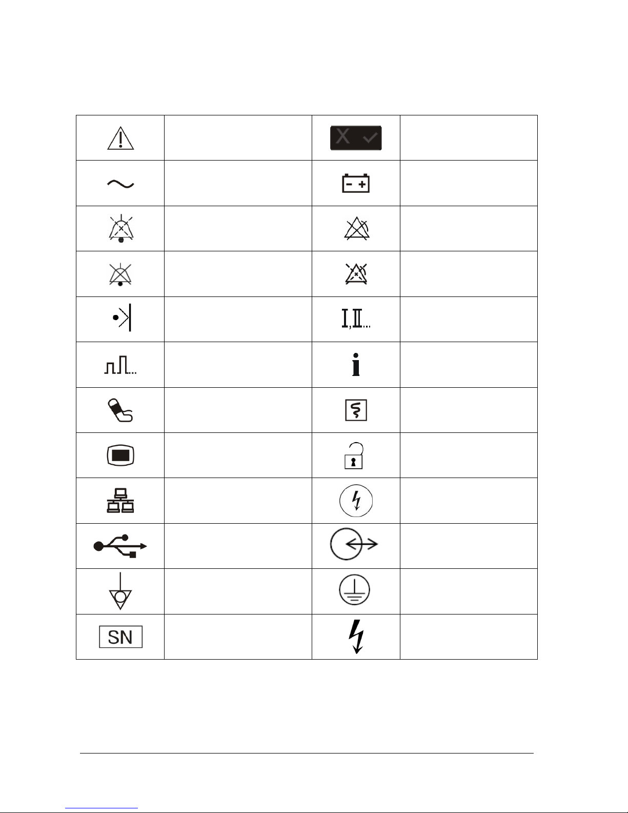
1.2 Equipment Symbols
Caution (Attention, consult
accompanying documents)
Status indicator
Alternating current
Battery indicator
Audio paused
Alarm off
Audio off
Alarm paused
Marker
Lead select
Gain select
Event summary
NIBP start/stop key
Graphical recorder
Menu
Unlocking
Network connector
Shock button
USB connector
Input/Output
Equipotentiality
Protective earth (ground)
Serial number
Dangerous voltage
Page 21
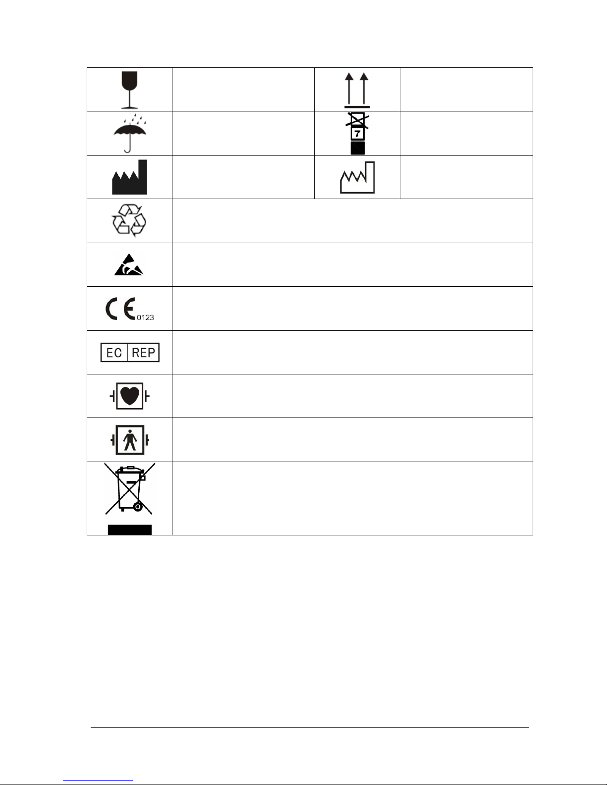
1-5
Fragile
Right side up
Keep dry
Maximum stacks
Manufacturer
Date of manufacture
General symbol for recovery/recyclable
Electrostatic sensitive devices
Mark of conformity to European Medical Device Directive 93/42/EEC
Authorised representative in the European community
DEFIBRILLATION-PROOF TYPE CF APPLIED PART
DEFIBRILLATION-PROOF TYPE BF APPLIED PART
Dispose of in accordance to your country’s requirements
Page 22

1-6
FOR YOUR NOTES
Page 23

2-1
2
The Basics
2.1 Overview
The BeneHeart (hereinafter called the equipment) is a lightweight and portable defibrillator/monitor. It provides four
operating modes: Monitor, Manual Defib, AED and Pacer.
In Monitor Mode, the equipment is intended for monitoring, displaying, reviewing, storing and printing multiple
physiological parameters and waveforms including ECG, pulse oximetry (SpO
2
), respiration (Resp), and non-invasive
blood pressure (NIBP).
In AED mode, the equipment automatically analyzes the patient’s ECG rhythm and indicates whether or not a shockable
rhythm is detected. Voice prompts provide easy-to-follow instructions and patient information to guide you through the
defibrillation process. Messages and flashing buttons are also presented to reinforce the voice prompts.
In the Manual Defib Mode, the operator analyzes the patient’s ECG, and, if appropriate, follows this procedure:
1 Select the Manual Defib mode, adjust the energy level if necessary;
2 Charge; and
3 Deliver the shock.
Defibrillation may be performed through paddles or multifunction electrode pads. In Manual Defib Mode, you can also
perform synchronized cardioversion. If desired, use of Manual Defib Mode may be password protected.
The Pacer Mode offers non-invasive transcutaneous pacing therapy. Pace pulses are delivered through multifunction
electrode pads. Use of Pacer Mode may also be password protected.
The equipment can be powered by smart lithium ion batteries which are rechargeable and maintenance-free. You can
easily determine the remaining battery charge by viewing the battery power gauge displayed on the screen or by
checking the indicator on the battery itself. An external AC mains or a DC power supply connected through an DC/AC
adapter may also be used as a power source and for continuous battery charging.
The equipment automatically stores patient data in an internal storage card. You can also export the data through the
USB port for viewing and editing on a PC through the data management software.
2.2 Intended Use
The equipment is intended for external defibrillation, internal defibrillation, synchronized cardioversion and
semi-automatic defibrillation (AED). It can also be used for non-invasive external pacing as well as ECG, SpO
2
, Resp, and
NIBP monitoring.
The equipment is for use in hospital and pre-hospital settings by qualified medical personnel trained in the operation of
the equipment and qualified by training in basic life support, advanced cardiac life support or defibrillation.
Page 24

2-2
2.2.1 AED
The AED mode is to be used only on cardio arrest patients who are at least 8 years. The patients must be:
Unresponsive
Not breathing or not breathing normally
2.2.2 Manual Defibrillation
Asynchronous defibrillation is the initial treatment for ventricular fibrillation and ventricular tachycardia in patients that
are pulseless and unresponsive. Synchronous defibrillation is intended for termination of atrial fibrillation.
2.2.3 Noninvasive Pacing
Noninvasive pacing therapy is intended for patients with symptomatic bradycardia. It can also be helpful in patients
with asystole, if performed early.
2.2.4 ECG
The ECG monitoring function is used to monitor and/or record the patient’s ECG waveform and heart rate.
2.2.5 Resp
The respiration monitoring function is used to continuously monitor the patient’s respiration rate and respiration
waveform.
2.2.6 SpO
2
The SpO2 function is intended to measure patient’s oxygen saturation in arterial blood.
2.2.7 NIBP
The NIBP function is intended for non-invasive measurement of a patient’s arterial blood pressure.
Page 25
2-3
2.3 Main Unit
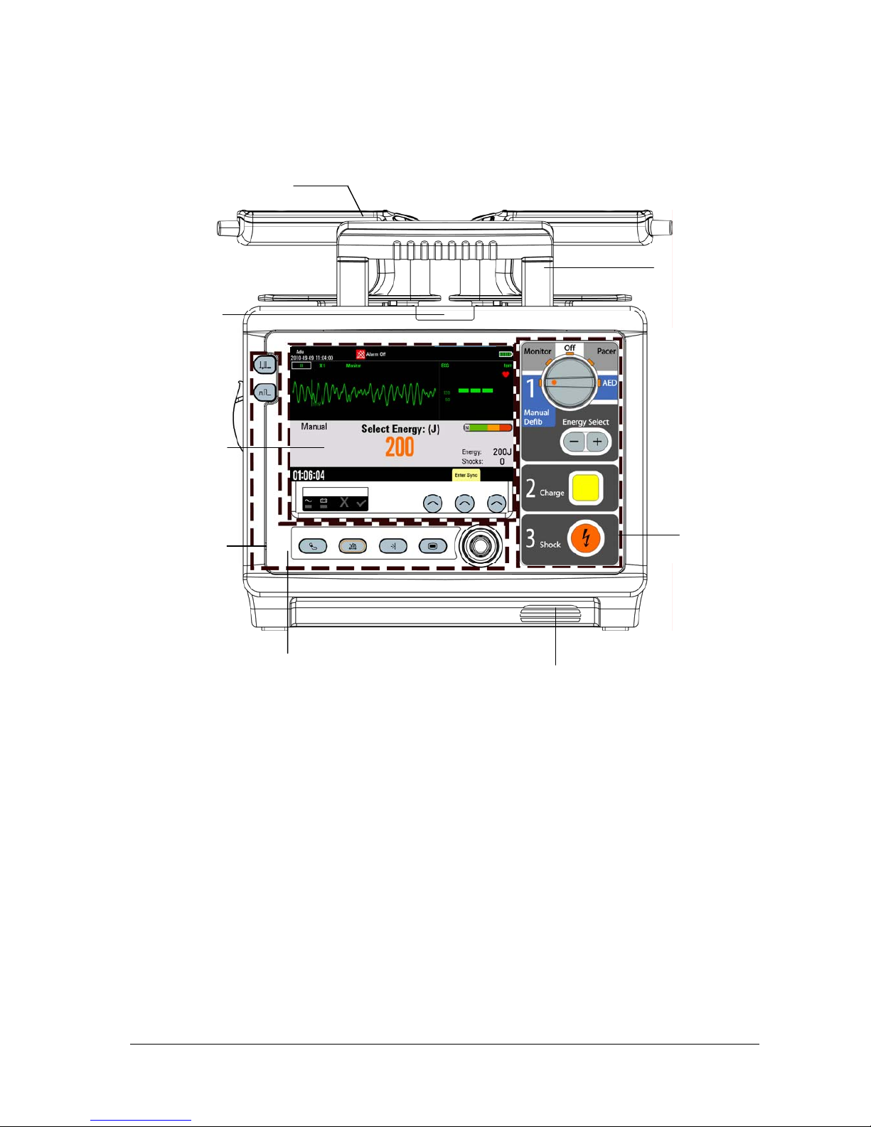
2.3.1 Front View
Area 1
Alarm
lamp
Area 2
External paddle
Handle
Area 3
Microphone
Speaker
Page 26
2-4
Area 1
1. Display screen
2. AC power indicator
Illuminated: when AC mains is connected.
Off: when AC mains is not connected.
3. Battery indicator
Yellow: when the battery is being charged.
Green: when the battery is fully charged or the equipment is run on battery.
Off: when no battery is installed or battery fails.
4. Status indicator (red cross)
Flashing: when a failure is detected or when battery is not installed if [No Battery] is configured as
[Status Indicator ON].
5. Status indicator (green tick)
Illuminated: when AC mains is connected, and the equipment operates properly.
NOTE
z
Both status indicators are off when AC mains is not connected if the equipment is turned off and no failure
is detected.
6. Soft keys
They are corresponding with the soft key labels located immediately above. The labels of the soft keys changes
according to the current operating mode.
1
2
3
4
5
6
Page 27
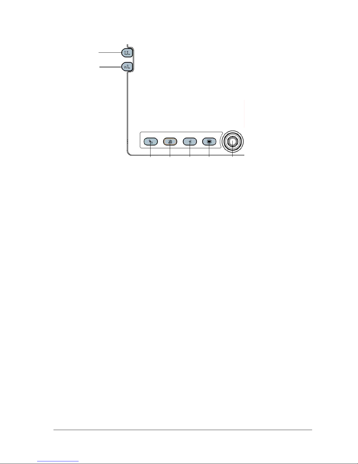
2-5
Area 2
1. Lead Select button
Press this button to select the lead of the first ECG waveform.
2. Gain select button
Press this button to select the size of the first ECG waveform.
3. NIBP button (for equipments configured with NIBP function)
Press this button to start or stop NIBP measurements.
Record button (for equipments without NIBP function)
Press this button to start a recording or stop the current recording.
4. Alarm Pause button
Press this button to pause, reactivate or switch off the alarms.
5. Mark Event button
Press it to manually mark specified events. If a menu has been open, pressing this button will close the menu.
6. Main Menu button
If no menu is displayed on the screen, pressing it will enter the main menu. If there is a menu displayed, pressing it
will close that menu.
7. Navigation knob
You can:
Rotate it clockwise or counterclockwise to move the cursor, or
Press it to confirm the selection.
2
3
5
7 6
4
1
Page 28
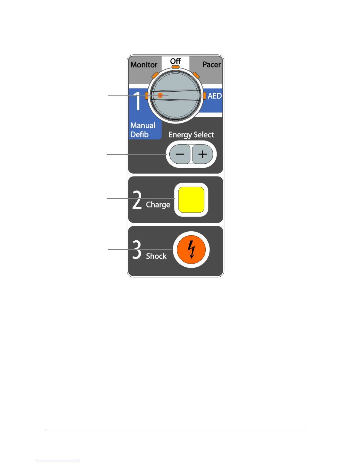
2-6
Area 3
1. Mode Select knob
Rotate this knob to select the operating mode or turn the equipment off.
2. Energy Select button
In Manual Defib mode, press this button to select energy level.
3. Charge button
Press this button to charge the defibrillator.
4. Shock button
Press this button to deliver a shock to the patient.
1
2
3
4
Page 29
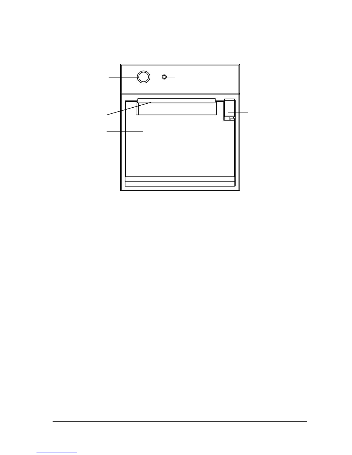
2-7
Recorder
1. Start/Stop Key
Press this key to start a recording or stop the current recording.
2. Indicator
Illuminated: when the recorder works correctly.
Flashes: when an error occurred to the recorder, or the recorder runs out of paper.
3. Paper outlet
4. Recorder door
5. Latch
3
4
2
1
5
Page 30
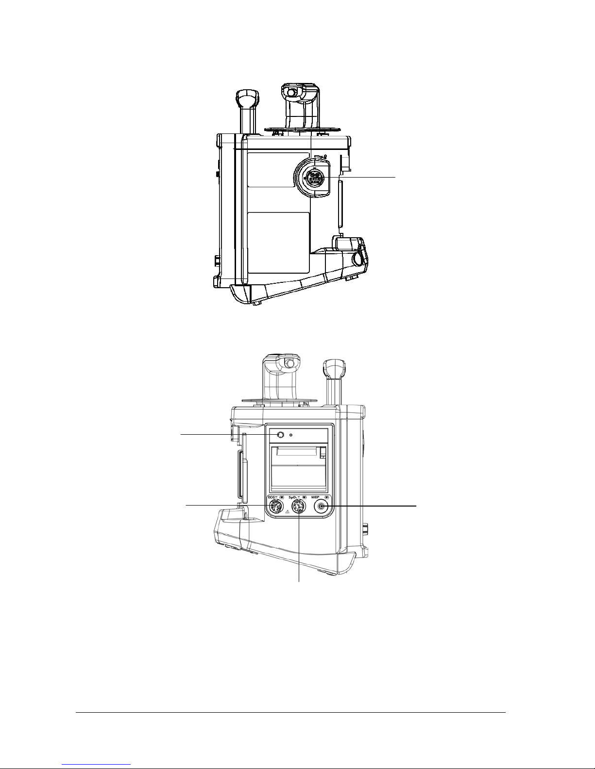
2-8
2.3.2 Side View
Therapy port is used to connect paddles cable or pads cable.
1. Recorder
2. ECG: ECG cable connector
3. SpO
2
: SpO2 sensor connector
4. NIBP: NIBP cuff connector
Therapy port
1
2
4
3
Page 31

2-9
2.3.3 Rear View
1. Hook
2. Battery
3. Equipotential grounding terminal
When the defibrillator/monitor and other devices are to be used together, their equipotential grounding terminals
should be connected together to eliminate the potential difference between them.
4. External power input
It connects an AC power cord or a DC/AC adapter to run the equipment respectively on the external AC mains or
DC power supply.
5. Multifunctional connector
It provides ECG output and defib synchronization input.
6. USB connector
7. Network connector
It is a standard RJ45 connector.
1
2
4
6
7
5
Page 32

2-10
2.3.4 External Paddles
1. Shock button
2. Energy Select button
3. Shock indicator
4. Charge button
5. Shock button
1
2
4
5
3
Sternum paddle Apex paddle
Page 33

2-11
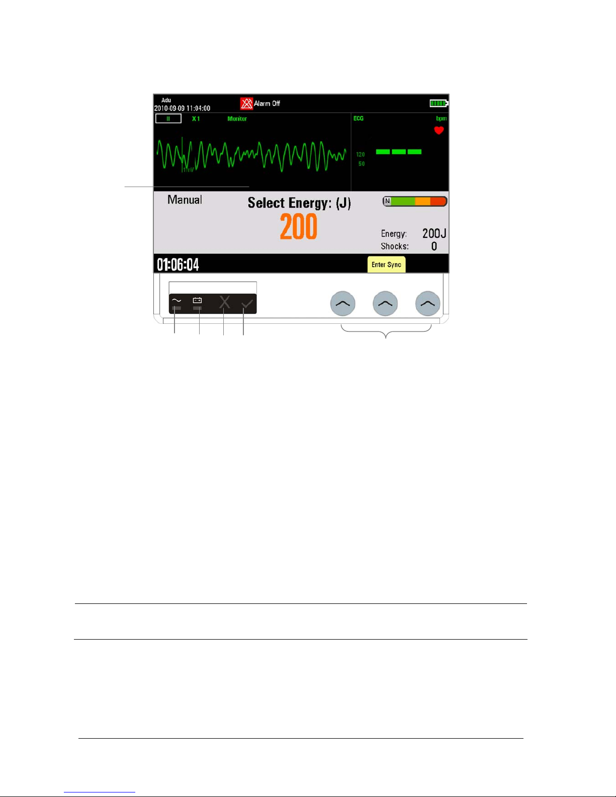
2.4 Display Views
A typical screen in Manual Defib Mode is shown below.
1. Patient Information area
This area shows patient name, patient category, paced status, and current date and time.
: indicates that the patient has an implanted pacemaker.
2. Alarm status symbols
indicates alarms are paused;
indicates all alarms are turned off;
indicates alarm sounds are paused;
indicates alarm sounds are turned off.
3. Physiological Alarm area
This area shows physiological alarm messages. When multiple alarms occur, they will be displayed circularly.
4. Technical Alarm area
This area shows technical alarm messages and prompt messages. When multiple messages come, they will be
displayed circularly.
5. Battery Status indicator
It indicates battery status. Refer to 18 Battery for details.
1
2
3
4
5
6
7
Page 34

2-12
6. Waveform area
This area shows measurement waveforms. The waveform label is displayed at the upper left corner of the
waveform.
7. Parameter area
This area shows measurement parameters. Each measurement module has a parameter block and the parameter
name is displayed at the upper left corner.
8. Manual Defib information area
This area shows the selected defibrillation energy, shock counter as well as prompt related to manual defibrillation.
9. Runtime area
This area shows the equipment's operating time since it is turned on.
10. Prompt area
This area shows the prompt information.
11. Soft Key area
The three soft key labels correspond to the soft key buttons located immediately below. The labels of the soft keys
changes according to the current display view and function. Soft key labels appearing as blank indicate that the
soft key is inactive.
Page 35

3-1
3
Basic Operations and Settings
3.1 Installation
WARNING
z
The equipment shall be installed by personnel authorized by the manufacturer.
z
The software copyright of the equipment is solely owned by the the manufacturer. No organization or
individual shall resort to juggling, copying, or exchanging it or to any other infringement on it in any form
or by any means without due permission.
z
Devices connected to the equipment must meet the requirements of the applicable IEC standards (e.g. IEC
60950 safety standards for information technology equipment and IEC 60601-1 safety standards for medical
electrical equipment). The system configuration must meet the requirements of the IEC 60601-1-1 medical
electrical systems standard. Any personnel who connect devices to the equipment’s signal input/output
port is responsible for providing evidence that the safety certification of the devices has been performed in
accordance to the IEC 60601-1-1. If you have any question, please contact the the manufacturer.
z
If it is not evident from the equipment specifications whether a particular combination is hazardous, for
example, due to summation of leakage currents, consult the manufacturers or else an expert in the field, to
ensure the necessary safety of all devices concerned will not be impaired by the proposed combination.
3.1.1 Unpacking and Checking
Before unpacking, examine the packing case carefully for signs of damage. If any damage is detected, contact the carrier
or the manufacturer. If the packing case is intact, open the package and remove the equipment and accessories carefully.
Check all materials against the packing list and check for any mechanical damage. If you have any question, please
contact us.
WARNING
z
Package material may contaminate the environment. Properly dispose of the package material according to
applicable waste control regulations and keep it out of children’s reach.
z
The equipment might be contaminated during storage and transport. Before use, please verify whether the
packages are intact, especially the packages of single use accessories. In case of any damage, do not apply it
to patients.
NOTE
z
Save the packing case and packaging material as they can be used if the equipment must be reshipped.
Page 36

3-2
3.1.2 Environmental Requirements
The operating environment of the equipment must meet the requirements specified in this manual.
The environment where the equipment is used shall be reasonably free from noises, vibration, dust, corrosive,
flammable and explosive substances. If the equipment is installed in a cabinet, sufficient space in front and behind shall
be left for convenient operation, maintenance and repair. Moreover, to maintain good ventilation, the equipment shall
be at least 2 inches (5 cm) away from around the cabinet.
When the equipment is moved from one place to another, condensation may occur as a result of temperature or
humidity difference. In this case, never start the system before the condensation disappears.
NOTE
z
Make sure that the operating environment of the equipment meets the specific requirements. Otherwise
unexpected consequences, e.g. damage to the equipment, could result.
3.2 Basic Operation
3.2.1 Turning Power On
Once the equipment is installed, you can get ready for monitoring and therapy:
1. Before turning on the equipment, check for any mechanical damage and make sure that all external cables,
plug-ins and accessories are properly connected.
2. Plug the power cord into the AC power source. If you run the equipment on battery power, ensure that the battery
is sufficiently charged. If you run the equipment on DC power supply, an DC/AC adapter we supply should be used.
3. Turn the Mode Select knob to enter the desired working mode. After the start-up screen is displayed, the system
gives a beep, and meanwhile, the alarm lamp is illuminated in yellow, and then turns red, and then turns off.
4. The equipment enters the screen of selected mode.
WARNING
z
Do not use the equipment for any monitoring or therapy procedure on a patient if you suspect it is not
working properly, or if it is mechanically damaged. Contact your service personnel or us.
3.2.2 Starting Monitoring or Therapy
1. Decide which measurements or therapy you want to make.
2. Check that the patient cables and sensors are correct.
3. Connect the required patient cables and sensors.
4. Enter the appropriate operating mode and check that the settings are proper for your patient.
Refer to the appropriate sections for details of how to perform patient monitoring and therapy.
Page 37

3-3
3.2.3 Disconnecting from Power
To disconnect the equipment from the AC power source, follow this procedure:
1. Confirm that the patient monitoring or therapy is completed.
2. Disconnect the patient cables and sensors from the patient.
3. Make sure to save or clear the patient data as required.
4. Turn the Mode Select Knob to Off. After 10 seconds, the equipment is shut down.
3.2.4 Auto Restoring to Last Configuration
During operation, you may make changes to some settings. However, these changes may not be saved as user
configuration. To prevent the changes from losing in case of sudden power failure, the equipment saves the settings in
real time. The saved settings are the latest configuration. In case of power failure, the equipment loads the latest
configuration if restarts within 60 seconds; it load the user configuration if restarts 120 seconds later after the power
failure; it may load either the latest configuration or the user configuration if restarts between 60 and 120 seconds after
the power failure.
3.3 Using the Main Menu
To enter the main menu, press the Main Menu button on the equipment’s front panel.
Other menus are similar to the main menu and contain the following parts:
1. Heading
2. Main body: displays options, buttons, prompt messages, etc. Pressing the menu button with “>>’’ enters a
submenu to reveal more options or information.
3. Exit button
3.4 Changing General Settings
3.4.1 Setting the Date and Time
1. Press the Main Menu button on the front panel, and then select [Others >>]→ [Configuration >>] enter the →
required password.
2. Select [General Setup >>].
3. Select [Date Format] from [yyyy-mm-dd], [mm-dd-yyyy] and [dd-mm-yyyy].
4. Select [Time Format] and toggle between [24h] and [12h].
5. Set [System Time].
1
2
3
Page 38

3-4
You can also set system time by selecting [Configuration >>]→[View Config]→[General Setup >>]. However, you
cannot select date format and time format in this case. After the completion of setting system time, exit the
configuration mode, and then the system will restart.
3.4.2 Adjusting the Screen Brightness
1. Press the Main Menu button on the front panel, and then select [Others >>].
2. Set [Brightness] to an appropriate level: 10 is the brightest, and 1 is the least bright.
You can also change screen brightness by entering configuration mode and selecting [Others] from the Configuration
Main menu.
3.4.3 Changing Key Volume
1. Press the Main Menu button on the front panel, and then select [Others >>].
2. Select [Key Volume] and then select an appropriate value. 0 means key volume off and 10 is the maximum volume.
You can also change key volume by entering configuration mode and selecting [Others] from the Configuration Main
menu.
3.4.4 Selecting High Contrast Mode
The equipment has the function of high contrast display so that the user can view the display under high ambient
illumination.
To enable the High Contrast display,
In the Monitor, Manual Defib and Pacer mode, press the Main Menu button on the front panel, and then select
[High Contrast]. To disable high contrast display, select [Full Color] in the Main Menu.
In AED mode, press the [High Contrast] soft key. To disable high contrast display, press the [Full Color] soft key.
Once High Contrast is selected, the system remains in high contract mode when you change the operating mode.
However, the setting will not be saved if the equipment is turned off.
Page 39

4-1
4
Managing Patients
4.1 Overview
Patient information management function enables you to edit and manage information of the current patient.
4.2 Editing Patient Information
You can edit patient information in Monitor, Manual Defib and Pacer mode.
To edit patient information,
1. Press the Main Menu button on the front panel, and then select [Patient Demographics >>] and then make
changes as desired.
2. Select [Others >>] to edit more patient information.
Archive ID is created automatically when the equipment is turned on. It is unchangeable. When the equipment is turned
off, the current patient is discharged and the archive ID turns to be historical archive ID
For a new patient, if patient category is changed, the system will restore the default alarm settings of this patient
category; if patient category is not changed, the alarm settings remain unchanged. If you restart the equipment after
normal power-off, the default alarm settings will be loaded.
Page 40

4-2
FOR YOUR NOTES
Page 41

5-1
5
Alarms
Alarms, triggered by a vital sign that appears abnormal or by technical problems of the equipment, are indicated to the
user by visual and audible alarm indications.
WARNING
z
A potential hazard exists if different alarm presets are used for the same or similar device in any single area,
e.g. an intensive care unit or cardiac operating room.
5.1 Alarm Categories
By nature, the equipment’s alarms can be classified into three categories: physiological alarms, technical alarms and
prompt messages.
1. Physiological alarms
Physiological alarms, also called patient status alarms, are triggered by a monitored parameter value that violates
set alarm limits or by an abnormal patient condition. Physiological alarm messages are displayed in the
physiological alarm area. In AED mode, no physiological alarm will be presented.
2. Technical alarms
Technical alarms, also called system status alarms, are triggered by a device malfunction or a patient data distortion
due to improper operation or system failure. Technical alarm messages are displayed in the technical alarm area.
3. Prompt messages
As a matter of fact, prompt messages are not alarm messages. Apart from the physiological and technical alarms,
the equipment also shows some messages indicating system status. Messages of this kind are usually displayed in
the prompt area. Therapy-related prompts are shown in corresponding information area. Some special prompts are
shown in dialog boxes.
Page 42

5-2
5.2 Alarm Levels
By severity, alarms can be classified into three categories: high level alarms, medium level alarms and low level alarms.
Physiological alarms Technical alarms
High level
Indicate that your patient is in a life
threatening situation, such as Asystole,
Vfib/Vtac and so forth, and an
emergency treatment is demanded.
Indicate a severe device malfunction or an improper operation,
which could make it possible that the equipment cannot detect
critical patient status or may cause therapy failed, and thus
threaten the patient’s life, such as low battery.
Medium
level
Indicate that your patient’s vital signs
appear abnormal and an immediate
treatment is required.
Indicate a device malfunction or an improper operation, which
may not threaten the patient’s life but may compromise patient
monitoring or therapy.
Low level
Indicate that you patient’s vital signs
appear abnormal and an immediate
treatment may be required.
Indicate a device malfunction or an improper operation, which
may compromise a certain function but will not threaten the
patient’s life.
5.3 Alarm Indicators
When an alarm occurs, the equipment indicates it to the user through visual or audible alarm indications.
Alarm lamp
Alarm tones
Alarm message
Flashing numeric
NOTE
z
When multiple alarms of different levels occur simultaneously, the equipment will select the alarm of the
highest level and give visual and audible alarm indications accordingly. Alarm messages will be displayed
circularly.
z
Some physiological alarms, such as Asystole, are exclusive. They have identical alarm tones and alarm lights
with normal high level physiological alarms, but their alarm messages are displayed exclusively. That is to
say, when an exclusive physiological alarm and a normal high level physiological alarms are triggered
simultaneously, only alarm message of the exclusive physiological alarm is displayed.
5.3.1 Alarm Lamps
If an alarm occurs, the alarm lamp will flash. The color and flashing frequency match the alarm level as follows:
High level alarms the lamp quickly flashes red.
Medium level alarms the lamp slowly flashes yellow.
Low level alarms the lamp lights yellow without flashing.
Page 43

5-3
5.3.2 Audible Alarms
The equipment uses different alarm tone patterns to match the alarm level:
High level alarms triple+double+triple+double beeps.
Medium level alarms triple beeps.
Low level alarms single beep.
5.3.3 Alarm Message
When an alarm occurs, the alarm message will appear in the technical or physiological alarm area. For physiological
alarms, the asterisk symbols (*) before the alarm message match the alarm level as follows:
High level alarms ***
Medium level alarms **
Low level alarms *
Additionally, the alarm message has different background color which matches the alarm level.
For physiological alarms
High level alarms red
Medium level alarms yellow
Low level alarms yellow
For technical alarms
High level alarms: red
Medium level alarms: yellow
Low level alarms: blue
5.3.4 Flashing Numeric
If an alarm triggered by an alarm limit violation occurs, the numeric of the measurement in alarm will flash every second,
and corresponding alarm limit will also flash at the same frequency indicating the alarm limit is violated.
5.3.5 Alarm Status Symbols
Apart from the aforementioned alarm indicators, the equipment still uses the following symbols telling the alarm status:
indicates all alarms are paused.
indicates all system alarms are turned off.
indicates alarm sounds are paused.
indicates alarm sounds are turned off.
Page 44

5-4
5.4 Alarm Tone Configuration
5.4.1 Changing the Alarm Volume
1. Press the Main Menu button on the front panel, and then select [Alarm Setup >>][→ Alm Volume >>].
2. Set [Alm Volume] to an appropriate level:
If [Audio Off] is enabled, alarm volume can be set to a value between 0 and 10, in which 0 means audio off and
10 the maximum volume level.
If [Audio Off] is disabled, alarm volume can be set to a value between 1 and 10, in which 1 is the minimum
volume level and 10 the maximum.
To disable or enable [Audio Off], access configuration management.
The setting of alarm volume will not be saved when the system is power off.
You can also set alarm volume in configuration mode. In this case, the setting will be saved.
NOTE
z
You cannot adjust alarm volume when an alarm is switched off.
5.4.2 Setting the Interval between Alarm Sounds
1. Press the Main Menu button on the front panel, and then select [Others >>] [→ Configuration >>] enter the →
required password.
2. Select [Alarm Setup >>] to enter the [Alarm Setup] menu.
3. Respectively set [High Alarm Interval (s)], [Med Alarm Interval (s)] and [Low Alarm Interval (s)].
WARNING
z
Do not rely exclusively on audible alarm system. Setting alarm volume to a low level may result in a hazard
to the patient. Always keep the patient under close surveillance.
5.5 Understanding the Alarm Setup Menu
Press the Main Menu button on the front panel, and then select [Alarm Setup >>] to enter the Alarm Setup menu.
Page 45

5-5
5.5.1 Setting Alarm Properties for All Parameters
In the main menu, select [Alarm Setup >>][→ Para. Alarm >>] to enter the Para. Alarm setup menu, where you can
review and set alarm limits, alarm switches, alarm level and alarm recordings for all parameters.
When a parameter alarm is switched on, the equipment gives alarm indications in accordance with the preset alarm
level and stores related waveforms and parameter values.
When a parameter alarm is switched off, the alarm off symbol “ ” is displayed in the parameter window.
If the measurement’s [On/Off] and [Record] are set to [On], automatic recording of all the measurement numerics
and related waveforms is possible when a measurement alarm occurs.
To reset the default settings, select the [Defaults] button.
NOTE
z
You cannot simultaneously switch on HR and PR alarms. In the case that PR alarm is on, switching on HR
alarm will automatically turn off PR alarm, and vice versa.
You can also set parameter alarm properties by selecting a parameter window and select [Para. Alarm >>] in the
pop-up menu.
WARNING
z
Make sure that the alarm limits settings are appropriate for your patient before patient monitoring.
z
Setting the alarm limit to an extreme value may cause the alarm system to be ineffective. For example, high
oxygen levels may predispose a premature infant to retrolental fibroplasia. If this is a consideration, do NOT
set the SpO
2
high alarm limit to 100%, which is equivalent to switching the alarm off.
Page 46

5-6
5.5.2 Adjusting Alarm Limits Automatically
The defibrillator/monitor can automatically adjust the patient’s alarm limits according to the measured vital signs. When
[Auto Limits] is selected, the equipment automatically calculates alarm limits based on the latest measured parameter
values.
To enable auto alarm limits, press the Main Menu button on the equipment’s front panel, and then select [Alarm Setup
>>][→ Para. Alarm>>][→ Auto Limits].
You can also access [Auto Limits] by select a parameter window to enter the [Para. Alarm] menu.
When auto alarm limits have been applied, you can manually adjust the alarm limits through the Para. Alarm Setup
menu so that they are appropriate for your patient.
The defibrillator/monitor calculates the auto limits based on the following rules.
Low alarm limit High alarm limit
Module Parameter
Adult/
pediatric
Neonate
Adult/
pediatric
Neonate
Auto alarm limits
range
ECG HR
HR×0.8 or 40 bpm
(whichever is
greater)
(HR-30) or 90 bpm
(whichever is
greater)
HR×1.25 or 240
bpm whichever is
lower)
(HR + 40) or 200
bpm whichever is
lower)
Adult/pediatric: 35 to
240
Neonate: 55 to 225
Resp RR
RR×0.5 or 6/min
(whichever is
greater)
(RR-10) or 30/min
(whichever is
greater)
RR×1.5 or 30/min
(whichever is
lower)
(RR+25) or 85/min
(whichever is
lower)
Adult/pediatric:
6 to 55
Neonate: 10 to 90
SpO2
Same as the
default alarm limit
Same as the
default alarm limit
Same as the
default alarm limit
Same as the default
alarm limit
Same as the
measurement range
SpO2
PR
PR×0.8 or 40 bpm
(whichever is
greater)
(PR-30) or 90 bpm
(whichever is
greater)
PR×1.25 or 240
bpm whichever is
lower)
(PR + 40) or 200
bpm whichever is
lower)
Adult/pediatric: 35 to
240
Neonate: 55 to 225
NIBP-S
SYS × 0.68 + 10
mmHg
(SYS-15) or 45
mmHg (whichever
is greater)
SYS × 0.86 + 38
mmHg
(SYS + 15) or 105
mmHg (whichever
is lower)
Adult: 45 to 270
Pediatric: 45 to 185
Neonate: 35 to 115
NIBP-D
Dia × 0.68 + 6
mmHg
(Dia-15) or 20
mmHg (whichever
is greater)
Dia × 0.86 + 32
mmHg
(Dia + 15) or 80
mmHg (whichever
is lower)
Adult: 25 to 225
Pediatric: 25 to 150
Neonate: 20 to 90
NIBP
NIBP-M
Mean × 0.68 + 8
mmHg
(Mean-15) or 35
mmHg (whichever
is greater)
Mean × 0.86 + 35
mmHg
(Mean + 15) or 95
mmHg (whichever
is lower)
Adult: 30 to 245
Pediatric: 30 to 180
Neonate: 25 to 105
NOTE
z
You can enable auto alarm limits only when the current parameter measurement is within the auto alarm
limits range.
Page 47

5-7
5.6 Pausing Alarms
You can temporarily disable alarm indicators by pressing the hardkey on the equipment’s front. When alarms are
paused:
For physiological alarms, no alarm indication is shown. New physiological alarm will not be presented.
The remaining alarm pause time is displayed in the physiological alarm area.
For technical alarms, alarm sounds are paused, but alarm lamps and alarm messages remain presented.
is displayed in the sound symbol area. If a new technical alarm is triggered in the alarm paused period, the
alarm message will be displayed.
When the alarm pause time expires, the alarm paused status is automatically deactivated. You can also cancel the alarm
paused status by pressing the
hardkey.
The default alarm pause time is 2 minutes. To change alarm pause time,
1. Press the Main Menu button on the front panel, and then select [Others >>] [→ Configuration >>] enter the →
required password.
2. Select [Alarm Setup >>][→ Alarm Pause Time] and then select an appropriate value.
5.7 Switching Alarms Off
When an alarm is switched off, the alarm status is the same with that when an alarm is paused.
Alarms are switched off when:
The
hardkey is pressed if the [Alarm Pause Time] is set to [Permanent].
The equipment is switched to the Manual Defib mode. Or
The equipment exit synchronous defibrillation when operating in the Manual Defib mode.
The alarm off status is exited when,
The
hardkey is pressed, or
Sync Defib is switched on in Manual Defib mode.
Page 48

5-8
5.8 Pausing Alarm Sounds
You can press the [Audio Pause] softkey to pause alarm tones. In this case, the symbol will be displayed in the
sound symbol area indicating all system sounds are silenced temporarily. In the audio paused status, all alarm indicators
except audible alarm tones works properly. If alarms are switched off or paused, the [ Audio Pause] soft key is not
shown.
The audio paused status is exited when,
The [ Audio On] soft key is pressed.
Other alarms occur. Or
The
hardkey is pressed to permanently or temporarily switch off the alarms.
5.9 Switching Off Alarm Sounds
In the event that [Audio Off] is enabled, to switch off the alarm tone, set [Alm Volume] to 0 while operating in Monitor
mode, Manual Defib mode or Pacer mode. In the audio off status, appears in the sound symbol area. In this case,
the alarm status is the same with that when alarm tones are paused.
The audio off status is exited when:
The
hardkey is pressed. In this case, the equipment enters the alarm paused status and the alarm volume is
reset to the default level. The symbol
is displayed in the sound symbol area.
The [Audio Pause] soft key is pressed. In this case, the equipment enters the audio paused status and the alarm
volume is reset to the default level. The symbol
is displayed in the sound symbol area.
Operating mode is switched. Then the equipment enters the default alarm status of corresponding operating mode.
Or
Alarm volume is changed to a value between 1 and 10.
5.10 Reminder Tones
When alarms or alarm sounds are turned off, the equipment can give a reminder tone of a single beep every 60 seconds.
The reminder tone is switched off by default. You can switch it on by selecting [Alarm Setup]→[Reminder Tone]
through the Configuration Management Main menu. You can also change reminder volume. The default reminder
volume is [Med].
Page 49

5-9
5.11 Latching Alarms
The latching setting for physiological alarms defines how alarm indicators behave when you do not acknowledge them.
If an alarm is latched, alarm indications remain presented even though alarm conditions end, except that:
The parameter reading and violated alarm limit stop flashing.
The time when the alarm is last triggered is displayed behind the alarm message.
If an alarm is not latched, the alarm indications disappear as soon as the alarm conditions end.
To latch a physiological alarm,
1. Press the Main Menu button on the front panel, and then select [Others >>] [→ Configuration >>] enter the →
required password.
2. Select [Alarm Setup] and set [Latching Alarms] to [Yes].
Only physiological alarms can be latched.
You can clear the latched alarms by pressing the
hardkey.
5.12 Clearing Technical Alarms
For some technical alarms, their alarm lamp flashing and alarm tones are cleared and the alarm messages change to
prompt messages after the
hardkey or [Audio Pause] soft key is pressed. After the equipment restores the normal
alarm status, it can give alarm indications correctly in case these alarms are triggered again.
For some technical alarms, all their alarm indications are cleared after the
hardkey or [Audio Pause] soft key is
pressed. After the equipment restores the normal alarm status, it can give alarm indications correctly in case these
alarms are triggered again.
For others, their alarm tones are cleared but the alarm lamp flashing and alarm messages remain after the
hardkey
or [Audio Pause] soft key is pressed. After the equipment restores the normal alarm status, all the alarm indications will
continue if the alarm conditions still present.
Page 50

5-10
5.13 When an Alarm Occurs
When an alarm occurs, observe the following steps and take proper actions:
1. Check the patient’s condition.
2. Confirm the alarming parameter or alarm category.
3. Identify the alarm source.
4. Take proper action to eliminate the alarm condition.
5. Make sure the alarm condition is corrected.
For actions taken with regard to specific alarms, see Appendix D Alarm Messages.
Page 51

6-1
6
Monitoring ECG
6.1 Overview
The electrocardiogram (ECG) measures the electrical activity of the heart and displays it as waveforms and numerics. The
equipment enables ECG monitoring through 3-, 5- lead ECG sets, external paddles and multifunction electrode pads. If
both ECG sets and paddles/pads are connected, the configured ECG waveforms are displayed in the waveform area.
6.2 Safety
WARNING
z
Periodically inspect the electrode application site to ensure skin quality. If the skin quality changes, replace
the electrodes or change the application site.
z
Use defibrillation-proof ECG cables during defibrillation.
z
When monitoring a patient implanted with a pacemaker, be sure to select correct paced status. Otherwise,
the pacing pulses may be counted in the case of cardiac arrest or some arrhythmias. Do not completely rely
on the heart rate reading or the heart rate alarms. Always keep paced patients under close surveillance.
NOTE
z
When connecting electrodes and/or patient cables, make sure that the connectors never come into contact
with other conductive parts, or with earth. Particularly make sure that all of the ECG electrodes are attached
to the patient.
z
Interference from a non-grounded instrument near the patient and electrosurgery interference may cause
problems with the waveform.
z
If selected lead cannot provide valid ECG signals, a dash line is shown in the ECG waveform area.
z
Avoid using external paddles for ECG monitoring if possible.
z
Use the same type of ECG electrodes when monitoring ECG through ECG lead set.
Page 52

6-2
6.3 Monitoring View
You can access Monitor mode by switching the Mode Select knob to the Monitor position. When operating in Monitor
mode, the equipment displays up to two ECG waveforms, the heart rate reading, other available parameter values and
active alarm settings.
6.4 Preparing to Monitor ECG
6.4.1 ECG Monitoring with Electrodes
1. Prepare the patient’s skin. Proper skin preparation is necessary for good signal quality at the electrode, as the skin is
a poor conductor of electricity. To properly prepare the skin, choose flat areas and then follow this procedure:
Shave hair from skin at chosen sites.
Gently rub skin surface at application sites to remove dead skin cells.
Thoroughly clean the sites with mild soap and water. We do not recommend using ether or pure alcohol,
because this dries the skin and increases the resistance.
Dry the skin completely before applying the electrodes.
2. Attach the clips or snaps to the electrodes before placing them.
3. Place the electrodes on the patient.
4. Attach the lead wires to the ECG trunk cable and then plug the trunk cable into the equipment’s ECG connector.
5. Connect the ECG trunk cable to the equipment.
6. Switch the Mode Select knob to Monitor.
6.4.1.1 Placing Electrodes
3-Lead Placement
The following is a typical AHA electrode placement for a 3-lead ECG set:
RA placement: directly below the clavicle and near the right shoulder.
LA placement: directly below the clavicle and near the left shoulder.
LL placement: on the left lower abdomen.
Page 53

6-3
5-Lead Placement
The following is a typical AHA electrode placement for a 5-lead ECG set:
RA placement: directly below the clavicle and near the right shoulder.
LA placement: directly below the clavicle and near the left shoulder.
RL placement: on the right lower abdomen.
LL placement: on the left lower abdomen.
V placement: on the chest.
The chest (V) electrode can be placed on one of the following positions:
V1 placement: on the fourth intercostal space at the right sternal border.
V2 placement: on the fourth intercostal space at the left sternal border
V3 placement: midway between the V2 and V4 electrode positions.
V4 placement: on the fifth intercostal space at the left midclavicular line.
V5 placement: on the left anterior axillary line, horizontal with the V4 electrode
position.
V6 placement: on the left midaxillary line, horizontal with the V4 electrode
position.
V3R-V6R placement: on the right side of the chest in positions corresponding to
those on the left.
VE placement: over the xiphoid process.
V7 placement: on posterior chest at the left posterior axillary line in the fifth intercostal space.
V7R placement: on posterior chest at the left posterior axillary line in the fifth intercostal space.
Electrode Placement for Surgical Patients
The surgical site should be taken into consideration when placing electrodes on a surgical patient, e.g. for open-chest
surgery, the chest electrodes can be placed on the lateral chest or back. To reduce artifacts and interference from
electrosurgical units, you can place the limb electrodes close to the shoulders and lower abdomen and the chest
electrodes on the left side of the mid-chest. Do not place the electrodes on the upper arm. Otherwise, the ECG
waveform will be very small.
WARNING
z
When using electrosurgical units (ESU), place ECG electrodes between the ESU and its grounding plate to
prevent unwanted burns. Never entangle ESU cable and ECG cable together.
z
When using electrosurgical units (ESU), never place ECG electrodes near to the grounding plate of the ESU,
as this can cause a lot of interference on the ECG signal.
Page 54

6-4
6.4.2 ECG Monitoring with Paddles/Pads
1. Prepare the patient’s skin.
2. Apply the paddles/pads to the patient.
If multifunction electrode pads are used, apply pads according to the instructions for use indicated on pads
package. Use anterior-lateral placement.
If external paddles are used, remove the paddle set from the paddle tray by grasping the handles and pulling
them straight up. Apply conductive gel to paddle electrodes. Place the paddles to the patient’s chest using the
anterior-lateral placement.
3. If multifunction electrode pads are used, connect the pads to the pads cable.
4. Connect paddles/pads cable with the equipment if not connected.
Anterior-lateral Paddles/Pads placement
1. Place the RA pad or Sternum paddle on the patient’s upper right torso, lateral to the sternum and below the clavicle,
as shown below.
2. Place the LL pad, or Apex paddle to the patient’s left nipple in the midaxillary line, with the center of the electrode
in the midaxillary line, if possible. See the figure below.
NOTE
z
Anterior - lateral placement is the only placement that can be used for ECG monitoring with paddles/pads
accessories.
LL
RA
Apex paddle
Sternum
paddle
Page 55

6-5
6.4.3 Checking Paced Status
It is important to set the paced status correctly when you start monitoring ECG. The paced symbol is displayed in
the patient information area when the [Paced] is set to [Ye s ]. The pace pulse markers “︱” are shown on the ECG wave
when the patient has a paced signal.
To change the paced status, you can select either:
[Main Menu][→ Patient Demographics >>][→ Paced], or
The ECG parameter window to enter the [ECG Setup] menu, and then, select [Others >>][→ Paced],
and toggle between [Ye s ] and [No].
Warning
z
For paced patients, you must set [Paced] to [Yes]. If it is incorrectly set to [No], the patient monitor could
mistake a pace pulse for a QRS and fail to alarm when the ECG signal is too weak. Do not rely entirely on rate
meter alarms when monitoring patients with pacemakers. Always keep these patients under close
surveillance.
z
For non-paced patients, you must set [Paced] to [No]. If it is incorrectly set to [Yes], the equipment may be
unable to detect premature ventricular beats (including PVCs).
6.5 ECG Display
The figure below shows the ECG monitoring view in 5-lead mode. It is for reference only. Your display may be configured
to look slightly different.
PVCs values is shown only when arrhythmia analysis is switched on. When external paddles or multifunctional electrode
pads are used for ECG monitoring, the PVCs values is shown as “---”.
Lead label
Gain
Filter mode
Alarm limits
HR value
Heartbeat icon
PVC values
Page 56

6-6
6.6 Changing ECG Settings
6.6.1 Changing Lead Settings
6.6.1.1 Selecting Lead Type
1. Select the ECG parameter area to enter the [ECG Setup] menu.
2. Select [Lead Set] and toggle between [3-lead] and [5-lead].
You can also set lead type in the configuration mode:
1. Press the Menu button on the equipment’s front panel. In the Main Menu, select [Others >>][→ Configuration
>>]→enter the required password to enter the Configuration Main menu.
2. Select [ECG Setup][→ Lead Set] and toggle between [3-lead] and [5-lead].
6.6.1.2 Choosing AHA or IEC Lead Placement
1. Select [Main Menu][→ Others >>][→ Configuration >>]→enter the required password.
2. In the Configuration Main menu, select [ECG Setup][→ ECG Standard], and then select [AHA] or [IEC] according to
the standard that is applied to your hospital.
6.6.1.3 Choosing the Heart Rate Source
To compute heart rate and to detect and analyse arrhythmia more accurately, you can choose a lead of best quality
signals as the HR calculation lead. To do so, select [ECG1] from the [ECG Setup] menu and then select the lead you want.
The selected lead should have the following characteristics:
The QRS should be either completely above or below the baseline and it should not be biphasic.
The QRS should be tall and narrow.
The P-waves and T-waves should be less than 0.2mV.
Page 57

6-7
6.6.2 Changing ECG Wave Settings
You can select the ECG parameter area to enter the [ECG Setup] menu to set ECG cascade and wave speed. You can also
select the hot keys above the ECG waveform to change ECG lead, size and filter.
You can press the Lead Select button on the equipment’s front panel or use the Navigation knob to select the
lead hot key above the first ECG waveform to select a lead.
If the wave is too small or clipped, you can change its size by adjusting the gain select button on the front panel or
selecting the Size hot key above the ECG waveform.
When monitoring ECG through ECG lead set, filter mode is displayed above the first ECG waveform. The available
filter mode settings are [Monitor], [Therapy], and [Diagnostic]. The default is [Therapy]. To change filter mode,
select the filter mode hot key using the Navigation knob.
When monitoring ECG through pads/paddles, filter mode is always “Therapy” and is not shown..
In the [ECG Setup] menu, select [Sweep], and then choose an appropriate value. The faster the wave sweeps, the
wider the wave is. You can also access [Sweep] to adjust wave speed from the [ECG Setup] menu in the
Configuration mode.
In the [ECG Setup] menu, select [ECG Cascade] and toggle between [On] and [Off].
NOTE
z
For paced patients, you must set [Paced] to [Yes]. If it is incorrectly set to [No], the system may mistake an
internal pace pulse for a QRS or fail to alarm when the pacer is broken.
6.6.3 Switching the Notch Filter On or Off
The notch filter removes the AC line noise. When [Filter] is set to [Monitor] or [Therapy], the notch filter is always on.
When [Filter] is set to [Diagnostic], you can switch the notch filter on or off as required.
To switch on or off notch filter, select the ECG parameter area to enter the [ECG Setup] menu, and then select [Others
>>][→ Notch Filter] and toggle between [On] and [Off].
Switching on the notch filter is recommended when there is interference with the waveform.
Set notch frequency according to the electric power frequency of your country. Follow this procedure:
1. Press the Main Menu button on the front panel, and then select [Others >>] [→ Configuration >>]→enter the
required password.
2. Select [ECG Setup][→ Notch Filter] and then select [50Hz] or [60Hz] according to the power frequency.
Page 58

6-8
6.6.4 Adjusting Heartbeat Volume
In the case that ECG alarm is switched on, or both ECG alarm and PR alarm are switched off, heartbeat tone is issued.
To adjust the heartbeat volume,
Select the ECG parameter window to enter the [ECG Setup] menu, and then select [Others >>][→ QRS Volume], or
From the Configuration Main menu, select [ECG Setup] [→ QRS Volume],
and then select an appropriate setting. The heartbeat volume can be set between 0 and 10, in which 0 means off, and 10
is the maximum volume.
When a valid SpO
2
value exists, the system will adjust the pitch of the heartbeat tone according to the SpO2 value.
6.7 Arrhythmia Analysis
Arrhythmia analysis provides information about your patient’s condition, including heart rate and arrhythmia alarms.
NOTE
z
Arrhythmia analysis program is intended to detect ventricular arrhythmias. It is not designed to detect atrial
or supraventricular arrhythmias. It may incorrectly identify the presence or absence of an arrhythmia.
Therefore, a physician must analyze the arrhythmia information with other clinical findings.
z
The arrhythmia detection is not intended for neonatal patients.
6.7.1 Understanding the Arrhythmia Events
Arrhythmia event Description Category
Asystole No QRS complex for 4 consecutive seconds (in absence of ventricular fibrillation
or chaotic signals).
V-Fib/V-Tach A fibrillatory wave for 4 consecutive seconds.
A dominant rhythm of adjacent Vs and a HR > the V-Tach Heart Rate Limit.
Vtac The consecutive PVCs > Vtac PVCs limit, and the HR > the Vtac HR limit.
Vent. Brady The consecutive PVCs ≥ the Vbrd threshold and the ventricular HR < the Vbrd
Rate threshold.
Extreme Tachy The heart rate is greater than the extreme tachycardia limit.
Extreme Brady The heart rate is less than the extreme bradycardia limit.
Lethal
arrhythmia
PVCs/min PVCs/min exceeds high limit
PNP** No pace pulse detected for 1.75 x average R-to-R intervals following a QRS
complex (for paced patients only).
PNC** No QRS complex detected for 300 milliseconds following a pace pulse (for
paced patients only).
PVC One PVC detected in normal heartbeats.
Couplet Paired PVCs are detected.
VT>2 More than 2 consecutive PVCs within the last minute.
Nonlethal
arrhythmia
Page 59

6-9
Arrhythmia event Description Category
Bigeminy A dominant rhythm of N, V,N, V, N, V.
Trigeminy A dominant rhythm of N, N, V,N, N, V, N, N, V.
R ON T R on T detected in normal heartbeats.
Missed Beats* No beat detected for 1.75x average R-R interval for HR <120, or No beat for 1
second with HR >120 (for non-paced patients only), or No beat detected for
more than the set pause threshold.
Brady The average heart rate is less than 60 bpm.
Tachy The average heart rate is greater than 100 bpm.
Vent. Rhythm The consecutive PVCs > the Vbrd PVCs limit, and the HR is between Vbrd Rate
limit and the Vtac Rate limit.
Multif. PVC Multiform PVCs detected in Multif. PVC's Window (which is adjustable).
Nonsus. Vtac The consecutive PVCs < the Vtac PVCs limit but > 2, and HR > the Vtac Rate
limit.
Pause* No QRS detected within the set time threshold of pause.
Irr. Rhythm Consistently irregular rhythm.
*: indicates that this arrhythmia alarm is not presented when [Paced] is set to [Yes ].
**: indicates that this arrhythmia alarm is not presented when [Paced] is set to [No].
When multifunctional electrode pads are used for ECG monitoring, the equipment provides only 4 arrhythmia
alarms, including asystole, ventricular fibrillation/ventricular tachycardia, PNP, and PNC.
When paddles are used, the equipment provides only 3 arrhythmia alarms, including ventricular
fibrillation/ventricular tachycardia, PNP, and PNC.
6.7.2 Switching Arrhythmia Analysis On and Off
To switch arrhythmia analysis on or off:
1. Select the ECG parameter area to enter the [ECG Setup] menu. Select [Arrhythmia >>].
2. Select [Arrhthmia] and toggle between [On] and [Off].
You can also switch arrhythmia analysis on or off in the Configuration mode. Follow this procedure: Enter the
Configuration Main menu. Select [ECG Setup][→ Arrhythmia] and toggle between [On] and [Off].
Page 60

6-10
6.7.3 Changing Arrhythmia Alarm Settings
To change arrhythmia alarm settings, select the ECG parameter area to enter the [ECG Setup] menu, and then select
[Arrhythmia >>]→[Arrh. Alarm] menu, where you can set alarm switch, alarm level and alarm record switch for all the
arrhythmia events..
You can also set arrhythmia alarm properties in the Configuration mode through the ECG Setup menu.
NOTE
z
The alarm level for asystole, ventricular fibrillation, ventricular tachycardia, ventricular bradycardia,
extreme bradycardia, and extreme tachycardia alarms is always high and unchangeable. These alarms are
always on. As long as the alarm condition occurs, corresponding alarm will be triggered whether arrhythmia
analysis is switched on or off.
6.7.4 Changing Arrhythmia Threshold Settings
To change arrhythmia threshold settings, select the ECG parameter window→[Arrhythmia >>]→[Arrh. Threshold >>].
In case an arrhythmia violates its threshold, an alarm will be triggered. The setting of Asystole Delay is linked to ARR
relearning. When HR is less than 30 bpm, it is recommended to set Asystole Delay to 10 seconds.
Arrh. event Range Default Step Unit
PVCs High 1 to 10 10 1 /
Asystole. Delay 2 to 10 5 1 s
Tachy 60 to 300 Adult: 120
Pediatric: 160
5 bpm
Brady 15 to 120 Adult: 50
Pediatric: 75
5 bpm
Extreme Tachy 60 to 300 Adult: 160
Pediatric: 180
5 bpm
Extreme Brady 15 to 120 Adult: 35
Pediatric: 50
5 bpm
Multif. PVCs Window 3 to 31 15 1 Beats
V-Tach Rate 100 to 200 130 5 bpm
V-Tach PVCs 3 to 12 6 1 Beats
Pause Time 1.5, 2.0, 2.5 2.0 / s
Vbrd Rate 15 to 60 40 5 bpm
Vbrd PVCs 3 to 99 5 1 Beats
You can also set arrhythmia threshold from the ECG Setup menu in the configuration mode.
Page 61

6-11
6.7.5 Initiating Arrhythmia Relearning Manually
Normally arrhythmia relearning allows the equipment to learn new ECG patterns to correct arrhythmia alarms and heart
rate value. We suggest you to manually initiate arrhythmia relearning when you suspect the result of arrhythmia
analysis.
To initiate relearning manually, select the ECG parameter window to enter the [ECG Setup] menu, select [Arrhythmia
>>][→ Relearn Arrh.]. When the equipment is learning, the message “Learning ECG” is displayed in the technical alarm
area.
NOTE
z
Arrhythmia relearning in the case of ventricular tachycardia may affect correct arrhythmia alarm.
6.7.6 Automatic Arrhythmia Relearn
Arrhythmia relearning is initiated automatically whenever:
The ECG lead or lead label is changed
The ECG lead is re-connected
Patient category is changed
The paced status is changed,
Arrhythmia analysis is switched on
[Stop Calibrating] is selected after ECG calibration is completed.
6.8 Calibrating ECG
The ECG signal may be inaccurate due to hardware or software problems. As a result, the ECG wave amplitude becomes
greater or smaller. In that case, you can perform ECG calibration to check if the ECG wave amplitude is in normal range.
1. Select ECG filter hot key. Turn the navigation knob to select [Diagnostic] mode.
2. Select the ECG parameter area to enter the [ECG Setup] menu.
3. Select [Others >>][→ Calibrate]. In this case, a square wave appears on the screen and the message “Calibrating
ECG” is displayed.
4. Compare the amplitude of the square wave with the 1 mV wave scale. The difference should be within 5%.
5. After the calibration is completed, select [Stop Calibrating].
You can print out the waveform and wave scale and then measure the difference between them if necessary. If the
difference exceeds 5%, contact your service personnel.
Page 62

6-12
FOR YOUR NOTES
Page 63

7-1
7
AED
7.1 Overview
This chapter describes how to operate the equipment in AED Mode. While operating in AED Mode, the equipment
analyses the patient’s ECG waveforms and guides you through the defibrillation process.
The equipment starts analyzing the patient’s heart rhythm immediately after entering AED mode. When a shockable
rhythm is detected, the equipment gives a prompt and automatically starts charging. If a shockable rhythm is not
detected, a “No shock advised” prompt is given. Smart defibrillation analysis goes through automated external
defibrillation until the equipment enters CPR or abnormal pads connection occurs.
While operating in AED Mode, the capabilities of the device are limited to those essential to the performance of
semi-automated external defibrillation. Only ECG signals acquired through pads are displayed. Previously set alarms and
scheduled measurements are indefinitely paused and entry of patient information is disabled. Additionally, the Lead
Select, Alarm Pause, and Main Menu buttons are inactive.
7.2 Safety
DANGER
z
Defibrillation current can cause operator or bystander severe injury or even death. Never touch the patient
or any equipment connected to the patient (including the bed or gurney) during defibrillation.
z
Avoid contact between parts of the patient’s body such as exposed skin of head or limbs, conductive fluids
such as gel, blood, or saline, and metal objects such as a bed frame or a stretcher which may provide
unwanted pathways for the defibrillating current.
z
Do not allow multifunction electrode pads to touch each other or to touch other ECG monitoring electrodes,
lead wires, dressings, etc. Contact with metal objects may cause electrical arcing and patient skin burns
during defibrillation and may divert current away from the heart.
z
To avoid explosion hazard, do not use the equipment in the presence of oxygen-rich atmospheres,
flammable anesthetics, or other flammable agents (such as gasoline). Keep the equipment and the
operating environment dry and clean.
Page 64

7-2
WARNING
z
During defibrillation, air pockets between the skin and multifunction electrode pads can cause patient skin
burns. To help prevent air pockets, make sure defibrillation pads are completely adhered to the skin.
z
Do not use dried-out pads.
z
In AED mode, this equipment is not designed to administer energy at pediatric joule settings. The American
Heart Association recommends AEDs be used only on patients who are more than eight years old.
CAUTION
z
Aggressive handling of multifunction electrode pads in storage or prior to use can damage the pads. Discard
the pads if they become damaged.
z
For patients with implantable pacemaker, the sensitivity and specificity of AED algorithm may be impaired.
7.3 AED View
A typical screen in AED Mode is shown below.
In AED mode, HR numeric and one ECG waveform acquired from the multifunction electrode pads are displayed. Below
the ECG is the information area which displays the defibrillation mode, prompt message, contact impedance indicator,,
selected energy and a shock counter.
For details about the contact impedance indicator, refer to 8.7 Contact Impedance Indicator.
Page 65

7-3
7.4 AED Procedure
Confirm that the patient is unresponsive, not breathing or not breathing normally.
Then:
1. Remove clothing from the patient’s chest. Wipe moisture from the patient’s chest and, if necessary, clip or shave
excessive chest hair.
2. Apply multifunction electrode pads to the patient as directed on the pads package. Use anterior-lateral placement.
3. Connect the pads with pads cable, and then plug the pads cable in the equipment’s therapy port.
4. Turn the Mode Select knob to AED.
When the equipment enters AED mode, it checks to see if the pads and pads cable are properly connected. If not, the
message “Connect Pads Cable” or “Apply Pads” will appear in the AED information area until corrective action has been
taken.
5. Follow the screen and voice prompts.
Once an ECG is detected through the multifunction electrode pads, the equipment automatically analyzes the patient’s
heart rhythm and warns you not to touch the patient. If a shockable rhythm is detected, the equipment charges
automatically.
You can switch on/off the voice prompt by accessing configuration management or adjust the volume of the voice
prompts by pressing the voice volume soft key.
6. Press the Shock button, if prompted.
Once charging is complete, the equipment gives prompt “Do Not Touch Patient! Press Shock Button”. Make sure no one is
touching the patient, bed or any equipment connected to the patient. Call out clearly and loudly “Stay Clear”. Then press
the Shock button on the front panel to deliver a shock to the patient.
Delivery of the shock is confirmed by the voice and screen prompt "Shock Delivered" and the shock counter on the
display is updated to reflect the number of shocks given. If the configured [Shock Series] is greater than one, the
equipment resumes analyzing the patient’s rhythm after the shock is delivered to see if the shock was successful. Voice
and text prompts continue to guide you through additional shocks.
NOTE
z
Do not use anterior-posterior pads placement (multifunction electrode pads placed on the patient’s chest
and back). The AED algorithm used by the equipment has not been validated using this placement.
z
Motion artifact may delay analysis or affect the ECG signal resulting in an inappropriate shock or no shock
advised message. Keep the patient still during ECG rhythm analysis.
z
The Shock button must be pressed to deliver a shock. The equipment will not automatically deliver a shock.
z
Impedance is the resistance between the defibrillator’s pads or paddles that the defibrillator must
Page 66

7-4
overcome to deliver an effective discharge of energy. The degree of impedance differs from patient to
patient and is affected by several factors including the presence of chest hair, moisture, and lotions or
powders on the skin. If the “Impedance too high. Shock not delivered” message appears, make sure that the
patient’s skin has been washed and dried and that any chest hair has been clipped. If the message persists,
change the pads and/or the pads cable.
7.5 Shock Advised
If a shockable rhythm is detected, the equipment automatically charges to the pre-configured energy level. A charging
tone is sounded, and the Shock button flashes when the equipment is fully charged.
Heart rhythm analysis continues while the equipment charges. If a rhythm change is detected before the shock is
delivered and a shock is no longer appropriate, the stored energy is removed internally.
Once you are prompted "Do Not Touch Patient! Press Shock Button", if you do not do so within the configured Auto
Disarm time interval, the equipment disarms itself and resumes analyzing.
When the equipment is being charged or have been fully charged, you can remove the charged energy at any time by
pressing the [Pause for CPR] soft key.
For defibrillation of adult patients, recommended energy level is 200 Joules.
7.6 No Shock Advised (NSA)
If a shockable rhythm is not detected, the equipment will tell you "No Shock Advised!".
If the [NSA Action] is set to [CPR]
The equipment enters CPR status and you will see and hear “No Shock Advised! Paused. If Needed, Begin CPR.” The
remaining pause time is displayed as shown below. The pause period can be defined by setting [CPR Time]
through configuration management.
Analysis resumes at the completion of the pause period or when you press the [Resume Analyzing] soft key in CPR
status.
If the [NSA Action] is set to [Monitor]
The equipment continues to monitor the ECG and automatically resumes analysis if a potentially shockable rhythm
is detected. You will hear “No Shock Advised! If needed press pause for CPR”. The message "No Shock Advised!" and
“Monitoring” are shown circularly in the AED information area.
You can define the frequency of these prompts by adjusting [Voice Prompts Interval] through configuration
management. You may press the [Pause for CPR] soft key to suspend monitoring and administer CPR. The pause
period can be defined by setting [CPR Time] through configuration management.
Page 67

7-5
7.7 CPR
If [Initial CPR Time] is not configured as Off, the system enters initial CPR if AED mode is entered. You can set [Initial
CPR Time] to an appropriate time or switch it off through configuration management.
After the shock series, ECG analysis pauses and the equipment enters the CPR status. Analysis resumes at the completion
of the pause period or when you press the [Resume Analyzing] soft key in CPR status.
In current shock series, the equipment enters the CPR status if you press the [Pause for CPR] soft key after a shock is
delivered. The CPR pause time is defined by setting [CPR Time] through configuration management.
NOTE
z
You can start analyzing patient’s heart rhythm again at any time by pressing the [Resume Analyzing] soft
key in CPR status.
7.7.1 CPR Metronome
The equipment provides a CPR metronome feature that can be used to encourage rescuers to perform chest
compression and ventilation at AHA/ERC recommended rate.
When activated, the metronome sounds 120 times per minute and give voice prompts to indicate the rescuers to
perform ventilation at configured compression/ventilation rate.
To activate or deactivate CPR metronome,
1. Move the Mode Select knob to Monitor, Manual Defib or Pacer. Press the Main Menu button on the front panel, and
then select→ [Others >>]→[Configuration >>]→Enter the required password.
2. Select [AED Setup] [→ CPR Metronome], and toggle between [On] and [Off].
The CPR metronome is activated by default. When CPR metronome is on, you can set the compression/ventilation rate
by selecting [CPR Mode]. The default rate is 30:2.
Page 68

7-6
Warning
z
The CPR metronome sounds do not indicate information regarding the patient’s condition. Because patient
status can change in a short time, the patient should be assessed at all times. Do not perform CPR on a
patient who is responsive or is breathing normally.
NOTE
z
CPR metronome and its volume is affected by the settings of [Voice Prompt] and [Voice Volume] in the AED
Setup menu.
7.8 AED Sound Recording
The equipment include a sound recording fucntion that can record the voice information during AED therapy. The
sound recording function can be configured on or off.
To switch on or off the sounding recording,
1. Move the Mode Select knob to Monitor, Manual Defib or Pacer. Press the Main Menu button on the front panel, and
then select [Others >>]→[Configuration >>]→Enter the required password.
2. Select [AED Setup] [→ Voice Recording], and toggle between [On] and [Off].
The symbol
is shown at the top right corner of the AED information area if the sounding recording function is
enabled.
The equipment can store up to 180 minutes, maximum 60 minutes for one patient, of sound recording.
7.9 AED Setup
1. Move the Mode Select knob to Monitor, Manual Defib or Pacer. Press the Main Menu button on the front panel, and
then select [Others >>]→[Configuration >>]→Enter the required password.
2. Select [AED Setup >>] to enter the AED Setup menu, and then change AED settings as desired.
Refer to Section 19.3.3 AED Setup Menu for details.
Page 69

8-1
8
Manual Defibrillation
8.1 Overview
This chapter explains how to prepare for and perform asynchronous defibrillation and synchronous cardioversion using
multifunction electrode pads and external paddles.
In Manual Defib Mode, you must assess the ECG waveforms, decide if defibrillation or cardioversion is indicated, select
appropriate energy setting, charge the equipment, and deliver the shock. Text messages and a contact impedance
indicator on the screen provide relevant information to guide your throughout the defibrillation process.
While operating manual defibrillation, besides ECG you can select to monitor SpO
2.
.
Alarms are turned off automatically when you enter Manual Defib mode. Pressing the Alarm Pause button can turn on
the alarms.
8.2 Safety
DANGER
z
Defibrillation current can cause operator or bystander severe injury or even death. Never touch the patient
or any equipment connected to the patient (including the bed or gurney) during defibrillation.
z
Avoid contact between parts of the patient’s body such as exposed skin of head or limbs, conductive fluids
such as gel, blood, or saline, and metal objects such as a bed frame or a stretcher which may provide
unwanted pathways for the defibrillating current.
z
Do not allow multifunction electrode pads and paddles to touch each other or to touch other ECG
monitoring electrodes, lead wires, dressings, etc. Contact with metal objects may cause electrical arcing and
patient skin burns during defibrillation and may divert current away from the heart.
z
During manual defibrillation, make sure your hands are dry and free from conductive gel to avoid shock
hazard.
z
Use care when operating this equipment close to oxygen sources (such as bag-valve-mask devices or
ventilator tubing). Turn off gas source or move source away from patient during defibrillation. This can
cause an explosion hazard.
Page 70

8-2
WARNING
z
During synchronous cardioversion, if monitoring patient’s ECG through external paddles, artifact
introduced by paddle movement may resemble an R-wave and trigger a defibrillation shock.
z
Do not use conductive liquid. Use only conductive gel specified by the equipment manufacturer.
z
If external paddles are used for defibrillation, apply the paddles tightly and evenly to the patient’s chest to
ensure good skin contact.
z
Never apply the paddles to human body to verify paddle connection.
z
Clinicians must select an appropriate energy level for defibrillation of pediatric patients.
CAUTION
z
Use of Manual Defib mode may be password protected. Make sure the operator knows and remembers the
password as defined in Configuration. Failure to enter correct password will prevent the delivery of manual
defibrillation therapy.
z
Clear the conductive gel from the external paddles at the completion of the therapy to prevent the paddles
from being corroded.
z
Prior to using this defibrillator, disconnect from the patient all equipment that is not defibrillator-protected.
z
Do not charge the equipment and deliver shock frequently in non-clinical situations. Otherwise equipment
damage could occur.
NOTE
z
Impedance is the resistance between the defibrillator’s pads or paddles that the defibrillator must
overcome to deliver an effective discharge of energy. The degree of impedance differs from patient to
patient and is affected by several factors including the presence of chest hair, moisture, and lotions or
powders on the skin. If the “Impedance too high. Shock not delivered” message appears, make sure that the
patient’s skin has been washed and dried and that any chest hair has been clipped. If the message persists,
change the pads and/or the pads cable.
z
Alarms are switched off automatically and the “Alarm Off” message is displayed when the equipment enters
the asynchronous defibrillation mode. Alarms remain off until toggled on by pressing the Alarm Pause
button, the Sync mode is entered, or the Mode Select knob is moved to Monitor or Pacer.
Page 71

8-3
8.3 Manual Defibrillation View
A typical screen in Manual Defib Mode is shown below.
In the enlarged ECG area, an ECG waveform and related parameters are displayed. In the middle of the screen,
defibrillation mode, synchronous icon, prompt message, selected energy, contact impedance indicator, and a shock
counter are displayed.
8.4 Manual Defibrillation Procedure
1. Remove clothing from the patient’s chest. Wipe moisture from the patient’s chest and, if necessary, clip or shave
excessive chest hair.
2. Connect the therapy cable to the therapy port. Push until you hear it click into place.
3. Apply multifunction electrode pads or external paddles to the patient.
If multifunction electrode pads are used, apply pads according to the instructions for use indicated on pads
package. Use anterior-lateral or anterior-posterior placement.
If external paddles are used, remove the paddle set from the paddle tray by grasping the handles and pulling
them straight up. Apply conductive gel to the electrode surface of each paddle. Place the paddles to the
patient’s chest using the anterior-lateral placement.
Do not touch this surface and the
part below.
Page 72

8-4
WARNING
z
Hold only the insulating parts of the paddle handles to avoid shock hazard during charging or shock
delivery.
4. Turn the Mode Select knob to Manual Defib.
You can access manual therapy directly, by confirmation or by password, which can be defined through
configuration management. The default setting is [Direct].
If [Manual Therapy Access] is set to [Direct], the equipment directly enters Manual Defib mode when the
Mode Select knob is switched to Manual Defib.
If [Manual Therapy Access] is set to [Confirmed], a dialog box pops up when the Mode Select knob is
switched to Manual Defib. You have to confirm whether to enter Manual Defib mode or not.
If [Manual Therapy Access] is set to [Password], a dialog box pops up, requiring the user to enter a password,
when the Mode Select knob is switched to Manual Defib. The equipment enters Manual Defib mode only after
correct password is entered.
5. Select energy.
You can select desired energy level by the adjusting the Energy Select buttons on the equipment’s front panel or
the Energy Select buttons on external paddles if external paddles are used.
Your current energy selection is shown in the defibrillation information area as shown below.
6. Charge
Press the Charge button on the front panel. If external paddles are used, the Charge button on the paddles may be
used instead. As the equipment charges, a progress bar is shown in the defibrillation information area. A charging
tone sounds until desired energy level is reached, when you will hear a charge done tone.
If you have to increase or decrease the selected energy during charging or after charging is complete, adjust the Energy
Select button to select the desired energy level as explained above. Then press the charge button again to restart
charging.
To remove the energy, press the [Disarm] soft key. If the Shock button is not pressed within the specified time period,
the equipment disarms automatically. You can define [Time to Auto Disarm] through configuration management.
7. Shock
Confirm that a shock is still indicated and that the equipment has charged to the selected energy level. Make sure
no one is touching the patient, bed or any equipment connected to the patient. Call out loudly and clearly, “Stay
Clear!”
If pads are used, press the flashing Shock button on the front panel to deliver a shock to the patient.
If external paddles are used, simultaneously press the Shock buttons located on the paddles to deliver a shock
to the patient.
Page 73

8-5
NOTE
z
Defibrillation is always performed through paddles or pads. However, during defibrillation you may choose
to monitor the ECG using an alternate ECG source (3- or 5-lead monitoring electrodes). If an alternate ECG
source is connected, any available lead may be displayed.
z
When external paddles are used, the Shock button on the equipment’s front panel is disabled.
z
For defibrillation of adult patients, recommended energy level is 200 Joules.
8.4.1 Using Pediatric Paddles
The external paddle set comes with pediatric paddles included. To use the pediatric paddle set, depress the latch at the
front of the external paddle set while pulling forward on the adult paddle electrodes.
To defibrillate, refer to the procedure as described in Section 8.4 Manual Defibrillation Procedure.
8.4.2 Using Internal Paddles
To defibrillate using internal paddles:
1. Turn on the defibrillator and enter the manual defib mode.
2. Select the appropriate paddle size.
3. Connect the paddles to the defibrillator by aligning the white pointer on the paddles cable with the arrow on the
therapy port. Push until you hear it click into place.
4. Select energy by pressing the Energy Select key on the equipment's front panel.
5. Place the conductive surface of paddle electrodes against the patient's right atrium and left ventricle, as shown in
the figure below:
6. Charge the defibrillator by pressing the Charge key on the front panel.
7. Make sure no one is touching the patient or anything connected to the patient.
8. Press the Shock key on the front panel.
Using internal paddles for synchronized cardioversion requires that the patient’s ECG be acquired through a standard
ECG cable. The patient’s ECG acquired through the internal paddles may be unreliable for synchronized cardioversion
due to excessive noise or artifact causing inappropriate R-wave detection.
Page 74

8-6
NOTE
z
When internal paddles are used for defibrillation, the energy selection is automatically limited to 50 joules
because of possible cardiac damage from higher energies.
z
Sterilize the internal paddles before each use. Otherwise, severe infection may result.
z
Clean the internal paddles after each use.
8.5 Synchronized Cardioversion
Synchronized Cardioversion allows you to synchronize delivery of the defibrillator shock with the R-wave of the ECG. You
may choose to perform synchronized cardioversion through either:
Multifunction electrode pads, or
External paddles
To use synchronized cardioversion, press the [Enter Sync] soft key in the asynchronous defibrillation mode. Then “Sync”
appears in the manual Defibrillation information area and a marker appears above each R-wave, see the figure below:
You can monitor ECG through multifunction electric pads, or external paddles, or electrodes connected to a 3- or 5-lead
ECG cable. Shock is delivered through either pads or paddles.For synchronized cardioversion, we recommend to acquire
patient’s ECG through ECG lead set
NOTE
z
When you enter synchronous cardioversion, monitoring alarms is reactivated autonomously.
Sync marker
R-wave marker
Page 75

8-7
8.5.1 Performing Synchronized Cardioversion
1. Connect the therapy cable and apply the multifunction electrode pads or external paddles to the patient. If ECG set
is used for ECG monitoring, connect the ECG trunk cable and apply the ECG electrodes to the patient, referring to 6
Monitoring ECG.
2. With the Mode Select knob in the Manual Defib position, press the [Enter Sync] soft key to activate the
synchronous cardioversion function.
3. Select a lead. The selected lead should have a clear signal and a large QRS complex.
4. Verify that a white R-wave marker appears above each R-wave. If the R-wave markers do not appear or do not
coincide with the R-waves, for example above the T-waves, select another lead.
5. Verify that the equipment enters the Sync mode, as indicated by the SYNC mark shown in the defibrillation
information area.
6. Press the Energy Select button to select a desired energy level.
7. Press the Charge button on the equipment’s front panel or, if using external paddles, the Charge button located on
the handle of Apex paddle.
8. Confirm that a shock is still indicated and that the equipment has charged to the selected energy level. Make sure
no one is touching the patient, bed or any equipment connected to the patient. Call out loudly and clearly, “Stay
Clear!”.
9. Press and hold the Shock button on the equipment or, if using external paddles, the Shock buttons on both
paddles. The shock will be delivered when the next R-wave is detected.
NOTE
z
During synchronized cardioversion, it is important to continue to hold the shock button (or the paddle’s
Shock buttons) until the shock is delivered. The equipment shocks with the next detected R -wave.
8.5.2 Delivering Additional Synchronized Shocks
If additional synchronized shocks are indicated, perform the following steps:
1. Make sure the equipment is still in Sync mode, as indicated by the presence of the Sync message in the
defibrillation information area.
2. Repeat Steps 4 to 9 as described above.
If [Sync after Shock] is set to [Ye s ], the equipment remains in the sync mode after a shock is delivered; if set to [No], the
equipment exits the sync mode and enters the asynchronous defibrillation mode after a shock.
8.5.3 Disabling the Sync Function
To switch off the Sync function, press the [Sync Off] soft key to enter the Manual Defib mode. .
Page 76

8-8
8.6 Remote Synchronized Cardioversion
The equipment can be configured to receive an ECG source from a remote patient monitor (such as a bedside patient
monitor) to perform synchronized cardioversion. To do so, the remote patient monitor shall have a sync out connector
and shall be connected to the defibrillator/monitor’s multifunctional connector with a synchronous cable.
To switch on remote synchronization, select [Manual Defib Setup]→[Remote Sync]→[On] through the Configuration
Main Menu.
The remote synchronization procedure is as follows:
1. Use a sync cable to connect the defibrillator/monitor with a bedside monitor through the defibrillator/monitor’s
multifunctional connector.
2. Switch on the equipment and enter the Manual Defib mode.
3. Press the [Enter Sync] soft key. In this case the “Select Sync Mode” dialog pops up.
4. Select [Remote] to enter remote synchronization. Then the message “Remote Sync” is presented.
5. Confirm a square wave on the defibrillator/monitor blinks with each detected R wave on the remote monitor as
shown below, indicating a sync pulse is received.
6. Connect the therapy cable to the therapy port. Push until you hear it click into place.
7. Apply multifunction electrode pads or external paddles to the patient.
8. Follow Steps 6 through 9 from 8.5.1 Performing Synchronized Cardioversion as described previously.
Page 77

8-9
NOTE
z
During remote synchronous defibrillation, the local defibrillator/monitor does not display the ECG
waveform. To view the patient’s ECG, check the remote monitor.
z
When you use an remote monitor as the ECG source, a biomedical technician must verify that the remote
monitor and the defibrillator/monitor combination will deliver a synchronized shock within 60 ms of the
peak of the R-wave.
8.7 Contact Impedance Indicator
Contact impedance indicator is used to indicate the impedance between the defibrillator’s pads or paddles in Manual
Defib or AED mode, as shown below:
Different levels of the measured impedance are shown as follows:
indicates the impedance is in normal range.
indicates the impedance is slightly higher for the defibrillation.
indicates the impedance is too high for the defibrillation or the pads or paddles are not
properly connected to the patient.
indicates the therapy cable is not properly connected.
To switch on the contact impedance indicator:
1. In Monitor, Manual Defib or Pacer mode, press the Main Menu button on the front panel, and then select→
[Others >>]→[Configuration >>]→Enter the required password.
2. Select [Manual Defibrillation] and set [Contact Impedance Indicator] to [On].
WARNING
z
It is recommended to perform defibrillation on a patient when the contact impedance is in normal range.
However, you can also perform defibrillation when the contact impedance is slightly higher.
Contact Impedance
Indicator
Page 78

8-10
FOR YOUR NOTES
Page 79

9-1
9
Noninvasive Pacing
9.1 Overview
In pacer mode, the patient’s ECG is monitored through ECG lead set and pace pulses are delivered through multifunction
electrode pads. The pads cannot be used to monitoring ECG rhythm and deliver pacing current at the same time.
A white pacing marker is shown on the ECG waveform each time a pacer pulse is delivered to the patient. If pacing in
demand mode, white R-wave marker also appears on the ECG waveform until capture occurs.
During pacing, both ECG and SpO
2
parameters continue to be monitored and parameter alarms remain active.
In demand mode pacing, a 3-lead or 5-lead ECG cable and electrodes are required to acquire ECG signal. Pace pulses are
delivered through multifunction electrode pads. However, the pads cannot be used to monitor the ECG and deliver pace
pulses simultaneously.
NOTE
z
In Pacer mode, arrhythmia analysis is supported and available arrhythmia alarms are asystole, ventricular
vibrillation and ventricular tachycardia.
9.2 Safety
WARNING
z
Heart rate displays and alarms function during pacing, but they can be unreliable. Observe the patient
closely while pacing. Do not rely on the indicated heart rate or heart rate alarms as a measure of the
patient’s perfusion status.
z
To avoid explosion hazard when pacing a patient who is receiving oxygen delivery, properly route the
oxygen delivery tube. Do not keep it close to the multifunction electrode pads.
Page 80

9-2
CAUTION
z
Use of Pacer mode may be password protected. Make sure the operator knows and remembers the
password as defined in Configuration. Failure to enter correct password will prevent the delivery of pacing
therapy.
z
For treatment of patients with implanted devices such as permanent pacemakers or
cardioverter-defibrillators, consult a physician and the instructions for use provided by the device’s
manufacturer
z
Prolonged noninvasive pacing may cause patient skin irritation and burns. Periodically inspect the
underlying skin and change ECG electrodes and multifunction electrode pads.
NOTE
z
If pacing is interrupted for any reason, the [Start Pacing] soft key must be pressed to resume pacing.
z
In pacer mode, you cannot change the patient’s internal paced status from the ECG Setup menu.
z
In the case that pads poorly contact the patient, the alarm “Pacer Stopped Abnormally” and “Pads Off” may
be presented.
z
Pads are not an available choice for the source of ECG waveform in Pacer mode.
9.3 Pacing View
A typical screen in pacer Mode is shown below.
In pacer mode, an ECG waveform, related parameters and waveforms are displayed. The pacer information area shows
the pacer mode, pacer rate and output, as well as pacer-related prompts and alarms. Soft keys available for setting
pacing functions are also displayed.
Page 81

9-3
9.4 Demand Mode versus Fixed Mode
The equipment can deliver paced pulses in either demand or fixed mode.
In demand mode, the pacer only delivers paced pulses when the patient’s heart rate is lower than the selected
pacing rate.
In fixed mode, the pacer delivers paced pulses at the selected rate.
During pacing, you can change pacer mode. Then the equipment continues to deliver pace pulses at selected pacer rate
and pacer output.
CAUTION
z
Use demand mode pacing whenever possible. Use fixed mode pacing if noise or artifact interferes with
proper sensing of R-wave or when monitoring electrodes are not available.
z
During fixed mode pacing, R-wave markers do not appear on the paced beats.
z
During demand mode pacing, spontaneous beats may be presented which are not associated with the
delivery of pace pulse. If the patient’s heart rate is above the pacer rate, pace pulses are not delivered and,
therefore, pacing markers do not appear.
9.5 Preparing for Pacing
1. If not pre-connected, connect the pads cable to the equipment. Then push until you hear it click into place.
2. Make sure the multifunction electrode pads packaging is intact and within the expiration date shown.
3. Connect the pads connector to the pads cable.
4. Apply the pads to the patient using anterior-lateral or anterior-posterior placement.
5. If pacing in demand mode, apply monitoring electrodes, and connect the ECG cable to the equipment. To get the
best monitoring signal, make sure there is adequate space between ECG electrodes and therapy electrodes. Refer
to 6.4.1 ECG Monitoring with Electrodes.
Page 82

9-4
9.5.1 Demand Mode Pacing
To pace in demand mode:
1. Turn the Mode Select knob to the Pacer position. Thus the pacing function is enabled in demand mode
automatically. ECG waveform of Lead II is displayed in the waveform area by default.
You can access manual therapy directly, by confirmation or by password, which can be defined through
configuration management. The default setting is [Direct].
If [Manual Therapy Access] is set to [Direct], the equipment directly enters Pacer mode when the Mode Select
knob is switched to Pacer.
If [Manual Therapy Access] is set to [Confirmed], a dialog box pops up when the Mode Select knob is
switched to Pacer. You have to confirm whether to enter Pacer mode or not.
If [Manual Therapy Access] is set to [Password], a dialog box pops up, requiring the user to enter a password,
when the Mode Select knob is switched to Pacer. The equipment enters Pacer mode only after correct
password is entered.
2. Select a lead with an easily detectable R-wave.
3. Verify that white R-wave markers appear above the R-waves, as shown in the figure below. If the R-wave markers do
not appear or do not coincide with the R-waves, for example above the T-waves, select another lead.
4. Select pacer rate. If necessary, select initial pacer output. To select pacer rate or pacer output, rotate the Navigation
knob to select an appropriate value and press it to confirm the selection. Do not forget to press the Navigation
knob to exit the setting after desired value is selected.
5. Press the [Start Pacing] soft key to start pacing. The message “Pacing” appears in the pacer information area. .
NOTE
z
Pacing will not start if there is a problem with the pads cable connection, pad patient connection, or ECG
monitoring electrodes connection. If either situation occurs, a message will appear in the pacer information
area to alert you that a lead is disconnected or that the pads have a poor connection.
6. Verify that white pacing markers appear on the ECG waveform, as shown below:
7. Adjust pacer output: increase pacer output until cardiac capture occurs (capture is indicated by the appearance of a
QRS complex after each pacing marker), and then decrease the output to the lowest level that still maintains
capture.
Pacing markers
Page 83

9-5
8. Verify the presence of a peripheral pulse.
You can temporarily withhold pacing pulse and observe the patient’s underlying rhythm by pressing and holding the
[4:1] soft key. This causes pacing pulse to be delivered at 1/4 of the defined pacer rate. To resume pacing at set rate,
release this key.
To stop pacing, press the [Stop Pacing] soft key. Pressing the [Start Pacing] soft key can resume pacing.
CAUTION
z
Routinely assess the patient’s cardiac output.
9.5.2 Fixed Mode Pacing
To pace in fixed mode:
1. Turn the Mode Select knob to the Pacer position.
2. Switch the pacer to the Fixed mode. To do so, move the cursor to the Pacer Mode hot key and rotate the Navigation
knob to select [Fix Mode]; then press it to confirm the selection, see the figure below:
3. If ECG electrodes are applied, use the Lead Select button to select the desired lead for viewing.
4. Select pacer rate. If necessary, select pacer output. To select pacer rate or pacer output, rotate the Navigation knob
to select an appropriate value and press it to confirm the selection.
5. Start pacing.
Press the [Start Pacing] soft key to start pacing. The message “Pacing” appears in the pacer information area. .
6. Verify that white pacing markers appear on the ECG waveform.
7. Adjust pacer output: increase pacer output until cardiac capture occurs (capture is indicated by the appearance of a
QRS complex after each pacing marker), and then decrease the output to the lowest level that still maintains
capture.
8. Verify the presence of a peripheral pulse.
You can temporarily withhold pacing pulse and observe the patient’s underlying rhythm by pressing and holding the
[4:1] soft key. This causes pacing pulse to be delivered at 1/4 of the defined pacer rate. To resume pacing at set rate,
release this key.
To stop pacing, press the [Stop Pacing] soft key.
Pacer Mode
hot key
Page 84

9-6
WARNING
z
Use care when handling the multifunction electrode pads on the patient to avoid shock hazard during
pacing.
z
If you are using the pacing function with battery power and the Low Battery alarm is presented, connect the
equipment to external power or install a fully charged battery.
CAUTION
z
The monitoring or pacing function may be unstable in the presence of ESU or other electronic devices.
Page 85

10-1
10
Monitoring Resp
10.1 Overview
Impedance respiration is measured across the thorax. When the patient is breathing or ventilated, the volume of air
changes in the lungs, resulting in impedance changes between the electrodes. Respiration rate (RR) is calculated from
these impedance changes, and a respiration waveform appears on the equipment screen.
10.2 Safety
WARNING
z
When monitoring the patient’s respiration, do not use ESU-proof ECG cables.
z
The respiration measurement does not recognize obstructive and mixed apneas: it only indicates an alarm
when a pre-adjusted time had elapsed since the last detected breath. The safety and effectiveness of the
respiration measurement method in the detection of apnea, especially the apnea of prematurity and apnea
of infancy, has not been established.
10.3 Resp View
RR alarm
high limit
RR alarm
low limit
RR reading
RR unit
Page 86

10-2
10.4 Placing Resp Electrodes
As the skin is a poor conductor of electricity, preparing the skin is necessary for a good Respiration signal. You can refer
to the ECG section for how to prepare the skin.
As the Respiration measurement adopts the standard ECG electrode placement, you can use different ECG cables (3-lead
or 5-lead). Since the respiration signal is measured between two ECG electrodes, if a standard ECG electrode placement
is applied, the two electrodes should be RA and LA of ECG Lead I, or RA and LL of ECG Lead II.
NOTE
z
To optimize the respiration waveform, place the RA and LA electrodes horizontally when monitoring
respiration with ECG Lead I; place the RA and LL electrodes diagonally when monitoring respiration with
ECG Lead II.
Lead I Lead II
Page 87

10-3
10.4.1 Optimizing Lead Placement for Resp
If you want to measure Resp and you are already measuring ECG, you may need to optimize the placement of the two
electrodes between which Resp will be measured. Repositioning ECG electrodes from standard positions results in
changes in the ECG waveform and may influence ST and arrhythmia interpretation.
Cardiac activity that affects the Resp waveform is called cardiac overlay. It happens when the Resp electrodes pick
up impedance changes caused by the rhythmic blood flow. Correct electrodes placement can help to reduce
cardiac overlay. Avoid the liver area and the ventricles of the heart in the line between the respiratory electrodes.
This is particularly important for neonates.
Some patients with restricted movement breathe mainly abdominally. In these cases, you may need to place the
left leg electrode on the left abdomen at the point of maximum abdominal expansion to optimize the respiratory
wave.
In clinical applications, some patients (especially neonates) expand their chests laterally, causing a negative
intrathoracic pressure. In these cases, it is better to place the two respiration electrodes in the right midaxillary and
the left lateral chest areas at the patient’s maximum point of the breathing movement to optimize the respiratory
waveform.
NOTE
z
Respiration monitoring is not for use on the patients who are very active, as this will cause false alarms.
10.4.2 Changing Resp Wave Settings
In the [Resp Setup] menu, you can:
Select [Gain] and then choose an appropriate setting. The bigger the gain is, the larger the wave amplitude is.
Select [Sweep] and then choose an appropriate setting. The faster the wave sweeps, the wider the wave is.
Select [Lead] to set lead for RESP monitoring.
In the [Resp Setup] menu, you can also change the [Apnea Alarm Delay] as desired.
Page 88

10-4
FOR YOUR NOTES
Page 89

11-1
11
Monitoring PR
11.1 Overview
The pulse numeric counts the arterial pulsations that result from the mechanical activity of the heart. You can display a
pulse from SpO
2
. The displayed pulse numeric is color-coded to match SpO2 parameter.
11.2 Adjusting Pulse Tone Volume
When PR alarm is switched on, the equipment gives out pulse tone. You can select the PR parameter area to enter the
[PR Setup] menu, and then adjust [QRS Volume] to change the volume of pulse tone .The default QRS volume is 2.
When a valid SpO
2
value exists, the system will adjust the pitch of pulse tone according to the SpO2 value.
PR value
PR unit
PR alarm high limit
PR alarm low limit
Page 90

11-2
FOR YOUR NOTES
Page 91

12-1
12
Monitoring SpO2
12.1 Introduction
SpO2 monitoring is a non-invasive technique used to measure the amount of oxygenated haemoglobin and pulse rate
by measuring the absorption of selected wavelengths of light. The light generated in the probe passes through the
tissue and is converted into electrical signals by the photodetector in the probe. The SpO
2
module processes the
electrical signal and displays a waveform and digital values for SpO
2
and pulse rate.
This device is calibrated to display functional oxygen saturation. It provides the following measurements.
1. Pleth wave: visual indication of patient’s pulse. The waveform is not normalized.
2. SpO
2
unit
3. SpO
2
alarm high limit
4. SpO
2
alarm low limit
5. Oxygen saturation of arterial blood (SpO
2
): percentage of oxygenated hemoglobin in relation to the sum of
oxyhemoglobin and deoxyhemoglobin.
6. Perfusion indicator: the pulsatile portion of the measured signal caused by arterial pulsation.
6
3
1
5
4
2
Page 92

12-2
12.2 Safety
WARNING
z
Use only SpO2 sensors specified in this manual. Follow the SpO2 sensor’s instructions for use and adhere to
all warnings and cautions.
z
When a trend toward patient deoxygenation is indicated, blood samples should be analyzed by a laboratory
co-oximeter to completely understand the patient’s condition.
z
Do not use SpO2 sensors during magnetic resonance imaging (MRI). Induced current could potentially cause
burns.
z
Prolonged continuous monitoring may increase the risk of undesirable changes in skin characteristics, such
as irritation, reddening, blistering or burns. Inspect the sensor site every two hours and move the sensor if
the skin quality changes. Change the application site every four hours. For neonates or patients with poor
peripheral blood circulation or sensitive skin, inspect the sensor site more frequently.
12.3 Identifying SpO
2
Modules
The equipment can be configured with any of the following SpO2 modules.
Mindray SpO
2
module;
Masimo SpO
2
module;
Nellcor SpO
2
module.
For Masimo or Nellcor SpO
2
modules, you will see corresponding logo on the equipment.
12.4 SpO
2
Monitoring Procedure
1. Select an appropriate sensor according to the module type, patient category and weight.
2. Clean the application site, e.g. removing colored nail polish from the application site.
3. Apply the sensor to the patient.
4. Select an appropriate adapter cable according to the connector type and connect it with the equipment.
5. Connect the sensor cable to the adapter cable.
6. Switch the Mode Select knob to Monitor.
NOTE
z
The SpO2 simulator can be used to check if the SpO2 sensor works properly. However, it cannot be used to
verify the accuracy of the SpO
2
sensor.
Page 93

12-3
12.5 Changing SpO
2
Settings
You can access the [SpO2 Setup] menu by selecting the SpO2 parameter area
12.5.1 Setting SpO
2
Sensitivity
For Mindray SpO2 module, you can set [Sensitivity] to [High], [Med] or [Low] from the [SpO2 Setup] menu. For Masimo
SpO
2
module, you can set [Sensitivity] to [Normal] or [High], in which [Normal] is equivalent to [Med].
When the [Sensitivity] is set to [High], the equipment is more sensitive to the changes to SpO
2
values, but the
measurement accuracy is relatively low. When monitoring critically ill patients whose pulsations are very weak, it is
strongly recommended that the sensitivity is set to [High].
When the [Sensitivity] is set to [Low], the equipment responds slowly to the changes of SpO
2
value, but the
measurement accuracy is relatively high.
12.5.2 Monitoring SpO
2
and NIBP on the Same Limb
When monitoring SpO2 and NIBP on the same limb simultaneously, you can switch [NIBP Simul] on from the [SpO2
Setup] menu to lock the SpO
2
alarm status until the NIBP measurement ends. If you switch [NIBP Simul] off, low
perfusion caused by NIBP measurement may lead to inaccurate SpO
2
readings and therefore cause false physiological
alarms.
12.5.3 Changing Averaging Time
The SpO2 value displayed on the screen is the average of data collected within a specific time. The shorter the averaging
time is, the quicker the equipment responds to changes in the patient’s oxygen saturation level, but the measurement
accuracy is relatively low. Contrarily, the longer the averaging time is, the slower the patient monitor responds to
changes in the patient’s oxygen saturation level, but the measurement accuracy will be improved. When monitoring
critically ill patients, selecting shorter averaging time will help understanding the patient’s condition.
To set the averaging time:
For Mindray SpO
2
module, set [Sensitivity] to [High], [Med] or [Low] from the [SpO2 Setup] menu, which
respectively correspond to 7 s, 9 s and 11 s.
For Masimo SpO
2
module, set [Averaging] to [2-4 s], [4-6 s], [8 s], [10 s], [12 s], [14 s] or [16 s] in the [SpO2 Setup]
menu.
Page 94

12-4
12.5.4 Sat-Seconds Alarm Management
With traditional alarm management, high and low alarm limits are set for monitoring oxygen saturation. During
monitoring, as soon as an alarm limit is violated, an audible alarm immediately sounds. When the patient’s SpO
2
value
fluctuates near an alarm limit, the alarm sounds each time the limit is violated. Such frequent alarm can be distracting.
The Sat-Seconds feature is available with the Nellcor SpO
2
module to decrease the likelihood of false alarms caused by
motion artifacts. The Sat-Seconds limit controls the amount of time that SpO
2
saturation may be outside the set limits
before an alarm sounds. The method of calculation is as follows: the number of percentage points that the SpO
2
saturation falls outside the alarm limit is multiplied by the number of seconds that it remains outside the limit. This can
be stated as the equation: Sat-Seconds= Points × Seconds
Only when the Sat-Seconds limit is reached, the monitor gives a Sat-Seconds alarm. The figure below demonstrates the
alarm response time with a Sat-Seconds limit set at 50 and a low SpO
2
limit set at 90%. In this example, the patient’s
SpO
2
drops to 88% (2 points) and remains there for 2 seconds. Then it drops to 86% (4 points) for 3 seconds, and then to
84% (6 points) for 6 seconds. The resulting Sat-Seconds are:
Points Seconds Sat-Seconds
2× 2 = 4
4× 3 = 12
6× 6 = 36
Total Sat-Seconds = 52
After approximately 10.9 seconds, a Sat-Second alarm would sound, because the limit of 50 Sat-Seconds would have
been exceeded.
Saturation levels may fluctuate rather than remaining steady for a period of several seconds. Normally, the patient’s SpO2
may fluctuate above and below an alarm limit, re-entering the non-alarm range several times. During such fluctuation,
the system sums the number of SpO
2
points, both positive and negative, until either the Sat-Seconds limit is reached, or
the patient’s SpO
2
re-enters the non-alarm range and remains there.
SpO
2
%
Second
Page 95

12-5
12.5.5 Changing the Speed of the Pleth Wave
In the [SpO2 Setup] menu, select [Sweep] and then select the appropriate setting. The faster the wave sweeps, the
wider the wave is.
12.6 SpO
2
Desat Alarm
The defibrillator/monitor provides an SpO2 Desat alarm. The SpO2 Desat alarm provides an additional limit setting below
the SpO
2
low limit setting to notify you of potentially life threatening decreases in oxygen saturation.
The SpO
2
Desat alarm is a high-level exclusive alarm. You cannot change its alarm level.
You can Press the Main Menu button on the front panel, and then select [Alarm Setup >>]→ [Para. Alarm >>]→[Desat],
or select a parameter window and then select [Para. Alarm >>]→ [Desat] to set the Desat alarm.
NOTE
z
In the case that the SpO2 low limit alarm value is set below the Desat limit, the the SpO2 low limit is
automatically adjusted to the Desat value.
12.7 Pitch Tone
The pitch tone function enables the equipment to give variable pitches of heartbeat tone or pulse tone as the patient’s
SpO
2
level changes. This equipment provides 22 levels of pitch tone. The pitch of heartbeat tone or pulse tone rises as
SpO
2
level increases and falls as SpO2 level decreases.
There are two pitch tone modes. The select pitch tone mode, select [SpO2 Setup]→[Pitch Tone] from the Configuration
Main menu and toggle between [Mode 1] and [Mode 2].
If the SpO
2
is disabled, the pitch tone function will be disabled also.
12.8 Measurement Limitations
If you doubt the SpO2 readings, check the patient’s vital signs first. Then check the equipment and SpO2 sensor. The
following factors may influence the accuracy of measurement:
Ambient light
Patient movement (active and imposed motion)
Diagnostic testing
Low perfusion
Electromagnetic interference, such as MRI environment
Electrosurgical units
Dysfunctional haemoglobin, such as carboxyhemoglobin (COHb)and methemoglobin (MetHb)
Presence of certain dyes, such as methylene and indigo carmine
Page 96

12-6
Inappropriate positioning of the SpO2 sensor, or use of incorrect SpO2
Drop of arterial blood flow to immeaurable level caused by shock, anemia, low temperature or vasoconstrictor.
12.9 Masimo Information
Masimo Patents
This device may be covered by one or more of the following US patents and foreign equivalents: 5,758,644, 6,011,986,
6,699,194, 7,215,986, 7,254,433, 7,530,955.
No Implied License
Possession or purchase of this device does not convey any express or implied license to use the device with
unauthorized sensors or cables which would, alone, or in combination with this device, fall within the scope of one or
more of the patents relating to this device.
12.10 Nellcor Information
Nellcor Patents
This device may be covered by one or more of the following US patents and foreign equivalents: 5,485,847, 5,676,141,
5,743,263, 6,035,223, 6,226,539, 6,411,833, 6,463,310, 6,591,123, 6,708,049, 7,016,715, 7,039,538, 7,120,479, 7,120,480,
7,142,142, 7,162,288, 7,190,985, 7,194,293, 7,209,774, 7,212,847, 7,400,919.
No Implied License
Possession or purchase of this device does not convey any express or implied license to use the device with
unauthorized replacement parts which would, alone, or in combination with this device, fall within the scope of one or
more of the patents relating to this device.
Page 97

13-1
13
NIBP
13.1 Introduction
Automatic non-invasive blood pressure monitoring uses the oscillometric method of measurement. It is intended for
adult, pediatric and neonatal patients. To understand how this method works, we’ll compare it to the auscultative
method.
With auscultation, the clinician listens to the blood pressure and determines the systolic and diastolic pressures. The
mean pressure can then be calculated with reference to these pressures as long as the arterial pressure curve is normal.
Since the equipment cannot hear the blood pressure, it measures cuff pressure oscillation amplitudes. Oscillations are
caused by blood pressure pulses against the cuff. The oscillation with the greatest amplitude is the mean pressure. Once
the mean pressure is determined, the systolic and diastolic pressures are calculated with reference to the mean.
Simply stated, auscultation measures systolic and diastolic pressures and the mean pressure is calculated. The
oscillometric method measures the mean pressure and determines the systolic and diastolic pressures.
As specified in IEC 60601-2-30/EN60601-2-30, NIBP monitoring is allowed while an electrosurgical operation is in
progress or a defibrillation shock is being delivered.
NIBP diagnostic significance must be decided by the doctor who performs the measurement.
NOTE
z
Blood pressure measurements determined with this device are equivalent to those obtained by a trained
observer using the cuff/stethoscope auscultatory method or an intra-arterial blood pressure measurement
device, within the limits prescribed by the American National Standard, Manual, electronic, or automated
sphygmomanometers.
13.2 Safety
WARNING
z
Be sure to select the correct patient category setting for your patient before measurement. Do not apply the
higher adult settings for pediatric or neonatal patients. Otherwise it may present a safety hazard.
z
Do not measure NIBP on patients with sickle-cell disease or any condition where skin damage has occurred
or is expected.
z
Use clinical judgment to determine whether to perform frequent unattended blood pressure measurements
on patients with severe blood clotting disorders because of the risk of hematoma in the limb fitted with the
cuff.
Page 98

13-2
z
Do not use the NIBP cuff on a limb with an intravenous infusion or arterial catheter in place. This could cause
tissue damage around the catheter when the infusion is slowed or blocked during cuff inflation.
z
If you doubt the NIBP readings, determines the patient’s vital signs by alternative means and then verify
that the equipment is working correctly.
13.3 Measurement Limitations
Measurements are impossible with heart rate extremes of less than 40 bpm or greater than 240 bpm, or if the patient is
on a heart-lung machine.
The measurement may be inaccurate or impossible,
If a regular arterial pressure pulse is hard to detect;
With excessive and continuous patient movement such as shivering or convulsions;
With cardiac arrhythmias;
Rapid blood pressure changes;
Severe shock or hypothermia that reduces blood flow to the peripheries;
Obesity, where a thick layer of fat surrounding a limb dampens the oscillations coming from the artery.
13.4 Measurement Modes
There are three modes of measuring NIBP:
Manual: measurement on demand.
Auto: continually repeated measurements at set intervals.
STAT: continually rapid series of measurements over a five minute period, then return to the previous mode.
13.5 Measuring Procedure
13.5.1 Preparing for NIBP Measurement
1. Verify that the patient category is correct. Change it if necessary.
2. Plug the air tubing into the equipment’s NIBP connector.
3. Select a correct sized cuff by referring to the limb circumference marked on the cuff. The width of the cuff should
be 40% (50% for neonates) of the limb circumference, or 2/3 of the upper arm’s length. The inflatable part of the
cuff should be long enough to encircle at least 50% to 80% of the limb.
4. Apply the cuff to an upper arm or thigh of the patient and make sure the Φ or marking on the cuff matches the
artery location. Do not wrap the cuff too tightly around the limb. It may cause discoloration, and ischemia of the
extremities. Make sure that the cuff edge falls within the marked range. If it does not, use a cuff that fits better.
5. Connect the cuff to the air tubing. Avoid compression or restriction of pressure tubes. Air must pass unrestricted
through the tubing.
6. Switch the Mode Select knob to Monitor.
Page 99

13-3
Warning
z
Continuous CUFF pressure due to connection tubing kinking may cause blood flow interference and
resulting harmful injury to the patient.
13.5.2 Starting and Stopping NIBP Measurements
You can start and stop NIBP measurements by using the hardkey on the equipment’s front panel.
13.5.3 Correcting the Measurement
The cuffed limb should be at the same level as the patient’s heart. If not, correct the measurement by:
Add 0.75 mmHg (0.10 kPa) for each centimeter higher, or
Deduct 0.75 mmHg (0.10 kPa) for each centimeter lower.
13.5.4 Enabling NIBP Auto Cycling
1. Select the NIBP parameter area to access the [NIBP Setup] menu.
2. Select [Interval] and then select a desired time interval. Selecting [Manual] switches to manual mode.
3. Start the measurement manually. The equipment will then automatically repeat NIBP measurements at the set time
interval.
Warning
z
Continuous non-invasive blood pressure measurements may cause purpura, ischemia and neuropathy in
the limb with the cuff. Inspect the application site regularly to ensure skin quality and inspect the extremity
of the cuffed limb for normal color, warmth and sensitivity. If any abnormity occurs, move the cuff to
another site or stop the blood pressure measurements immediately.
13.5.5 Starting a STAT Measurement
1. Select the NIBP parameter area to access the [NIBP Setup] menu.
2. Select [NIBP STAT]. The STAT mode initiates a 5-minute continuous, automatic NIBP measurement.
Page 100

13-4
13.6 Understanding the NIBP Numerics
The NIBP display shows numerics only as below. Your display may be configured to look slightly different.
1. Measurement mode
2. Pressure unit: mmHg or kPa
3. NIBP alarm high limit
4. NIBP alarm low limit
5. Time of last measurement
6. Systolic pressure
7. Diastolic pressure
8. Mean pressure at the completion of measurement, or cuff pressure during the measurement
13.7 Setting Initial Cuff Inflation Pressure
You can set the initial cuff inflation pressure manually. In the [NIBP Setup] menu, select [Initial Pressure] and then
select the appropriate setting. The cuff is inflated accordingly at the next NIBP measurement.
The table below list the setting range of initial cuff inflation pressure:
Patient category Range (mmHg) Default (mmHg) Accuracy (mmHg)
Adult 80 to 280 160
Pediatric 80 to 210 140
Neonate 60 to 140 90
10
NOTE
z
Setting initial cuff inflation pressure is disabled during NIBP measurement.
z
The initial cuff inflation pressure is restored to the default setting if NIBP module has been reset or patient
category has been changed.
13.8 Setting Pressure Unit
To set pressure unit, access configuration management. In the Configuration-Main menu, select [NIBP Setup]→[Press.
Unit] and toggle between [mmHg] and [kPa].
You can change NIBP unit only through configuration management.
21
3
4
5
7
6
8
 Loading...