

Page 1

BeneHeart D1
Automated External Defibrillator
Operator’s Manual
Page 2

Page 3

© 2013-2014 Shenzhen Mindray Bio-Medical Electronics Co., Ltd. All rights reserved.
For this Operator’s Manual, the issue date is 2014-01.
I
Page 4

Intellectual Property Statement
SHENZHEN MINDRAY BIO-MEDICAL ELECTRONICS CO., LTD. (hereinafter called Mindray) owns the intellectual property
rights to this Mindray product and this manual. This manual may refer to information protected by copyright or patents
and does not convey any license under the patent rights or copyright of Mindray, or of others.
Mindray intends to maintain the contents of this manual as confidential information. Disclosure of the information in
this manual in any manner whatsoever without the written permission of Mindray is strictly forbidden.
Release, amendment, reproduction, distribution, rental, adaptation, translation or any other derivative work of this
manual in any manner whatsoever without the written permission of Mindray is strictly forbidden.
, , and are the trademarks, registered or otherwise,
of Mindray in China and other countries. All other trademarks that appear in this manual are used only for informational
or editorial purposes. They are the property of their respective owners.
II
Page 5

Responsibility on the Manufacturer Party
Contents of this manual are subject to change without prior notice.
All information contained in this manual is believed to be correct. Mindray shall not be liable for errors contained herein
or for incidental or consequential damages in connection with the furnishing, performance, or use of this manual.
Mindray is responsible for the effects on safety, reliability and performance of this product, only if:
all installation operations, expansions, changes, modifications and repairs of this product are conducted by
Mindray authorized personnel;
the electrical installation of the relevant room complies with the applicable national and local requirements; and,
the product is used in accordance with the instructions for use.
WARNING
This equipment must be operated by skilled/trained clinical professionals.
It is important for the hospital or organization that employs this equipment to carry out a reasonable
service/maintenance plan. Neglect of this may result in machine breakdown or personal injury.
III
Page 6

Warranty
THIS WARRANTY IS EXCLUSIVE AND IS IN LIEU OF ALL OTHER WARRANTIES, EXPRESSED OR IMPLIED, INCLUDING
WARRANTIES OF MERCHANTABILITY OR FITNESS FOR ANY PARTICULAR PURPOSE.
Exemptions
Mindray's obligation or liability under this warranty does not include any transportation or other charges or liability for
direct, indirect or consequential damages or delay resulting from the improper use or application of the product or the
use of parts or accessories not approved by Mindray or repairs by people other than Mindray authorized personnel.
This warranty shall not extend to:
Malfunction or damage caused by improper use or man-made failure.
Malfunction or damage caused by unstable or out-of-range power input.
Malfunction or damage caused by force majeure such as fire and earthquake.
Malfunction or damage caused by improper operation or repair by unqualified or unauthorized service people.
Malfunction of the instrument or part whose serial number is not legible enough.
Others not caused by instrument or part itself.
Company Contact
Manufacturer: Shenzhen Mindray Bio-Medical Electronics Co., Ltd.
Address: Mindray Building, Keji 12th Road South, High-tech industrial park,
Nanshan, Shenzhen 518057, P.R.China
Website: www.mindray.com
E-mail Address: service@mindray.com.cn
Tel: +86 755 81888998
Fax: +86 755 26582680
EC-Representative: Shanghai International Holding Corp. GmbH (Europe)
Address: Eiffestraβe 80, 20537 Hamburg, Germany
Tel: 0049-40-2513175
Fax: 0049-40-255726
IV
Page 7

Preface
Manual Purpose
This manual contains the instructions necessary to operate the product safely and in accordance with its function and
intended use. Observance of this manual is a prerequisite for proper product performance and correct operation and
ensures patient and operator safety.
This manual is based on the maximum configuration and therefore some contents may not apply to your product. If you
have any question, please contact us.
This manual is an integral part of the product. It should always be kept close to the equipment so that it can be obtained
conveniently when needed.
Intended Audience
This manual is geared for clinical professionals who are expected to have a working knowledge of medical procedures,
practices and terminology as required for monitoring of critically ill patients.
Illustrations
All illustrations in this manual serve as examples only. They may not necessarily reflect the setup or data displayed on
your equipment.
Conventions
Italic text is used in this manual to quote the referenced chapters or sections.
[ ] is used to enclose screen texts.
→ is used to indicate operational procedures.
V
Page 8

FOR YOUR NOTES
VI
Page 9

Contents
1 Safety ............................................................................................................................................................................ 1-1
1.1 Safety Information .............................................................................................................................................................................................. 1-1
1.1.1 Dangers ................................................................................................................................................................................................... 1-1
1.1.2 Warnings ................................................................................................................................................................................................. 1-2
1.1.3 Cautions .................................................................................................................................................................................................. 1-3
1.1.4 Notes ........................................................................................................................................................................................................ 1-3
1.2 Equipment Symbols ........................................................................................................................................................................................... 1-4
2 The Basics ..................................................................................................................................................................... 2-1
2.1 Overview ................................................................................................................................................................................................................ 2-1
2.2 Intended Use ......................................................................................................................................................................................................... 2-1
2.2.1 AED ............................................................................................................................................................................................................ 2-2
2.2.2 Manual Defibrillation .......................................................................................................................................................................... 2-2
2.2.3 ECG ............................................................................................................................................................................................................ 2-2
2.3 Main Unit ................................................................................................................................................................................................................ 2-2
2.3.1 Front View ............................................................................................................................................................................................... 2-2
2.3.2 Side View ................................................................................................................................................................................................. 2-3
2.3.3 Rear View ................................................................................................................................................................................................. 2-4
2.4 Display Views......................................................................................................................................................................................................... 2-5
2.5 Soft Key Symbols ................................................................................................................................................................................................. 2-6
3 Basic Operations and Settings .................................................................................................................................... 3-1
3.1 Installation ............................................................................................................................................................................................................. 3-1
3.1.1 Unpacking and Checking ................................................................................................................................................................. 3-1
3.1.2 Environmental Requirements ......................................................................................................................................................... 3-2
3.1.3 Installing the Battery .......................................................................................................................................................................... 3-2
3.1.4 Connecting Electrode Pads .............................................................................................................................................................. 3-2
3.2 Basic Operations .................................................................................................................................................................................................. 3-3
3.2.1 Turning Power On ................................................................................................................................................................................ 3-3
3.2.2 Changing General Settings .............................................................................................................................................................. 3-3
3.2.3 Turning off the Equipment ............................................................................................................................................................... 3-4
3.2.4 Auto Restoring to Last Configuration ........................................................................................................................................... 3-4
3.3 Post Use Procedure ............................................................................................................................................................................................. 3-4
4 Alarms ........................................................................................................................................................................... 4-1
4.1 Alarm Categories ................................................................................................................................................................................................. 4-1
4.2 Alarm Levels .......................................................................................................................................................................................................... 4-1
4.3 Alarm Indicators ................................................................................................................................................................................................... 4-2
4.3.1 Audible Alarms ..................................................................................................................................................................................... 4-2
4.3.2 Alarm Message ..................................................................................................................................................................................... 4-2
4.3.3 Alarm Status Symbols ........................................................................................................................................................................ 4-2
4.4 Alarm Tone Configuration ................................................................................................................................................................................ 4-3
1
Page 10

4.4.1 Changing the Alarm Volume ........................................................................................................................................................... 4-3
4.4.2 Pausing Alarm Sounds ....................................................................................................................................................................... 4-3
4.4.3 Switching Off Alarm Sounds ........................................................................................................................................................... 4-3
4.5 Reminder Tones ................................................................................................................................................................................................... 4-4
4.6 Clearing Technical Alarms ................................................................................................................................................................................ 4-4
4.7 When an Alarm Occurs ...................................................................................................................................................................................... 4-4
5 AED ............................................................................................................................................................................... 5-1
5.1 Overview ................................................................................................................................................................................................................ 5-1
5.2 Safety ....................................................................................................................................................................................................................... 5-1
5.3 AED View ................................................................................................................................................................................................................ 5-2
5.4 AED Procedure ..................................................................................................................................................................................................... 5-3
5.5 Shock Advised ...................................................................................................................................................................................................... 5-4
5.6 No Shock Advised (NSA) ................................................................................................................................................................................... 5-5
5.7 CPR ........................................................................................................................................................................................................................... 5-5
5.7.1 CPR Metronome ................................................................................................................................................................................... 5-5
5.8 AED Sound Recording ....................................................................................................................................................................................... 5-6
5.9 AED Setup .............................................................................................................................................................................................................. 5-6
6 Manual Defibrillation (For Pro Only) .......................................................................................................................... 6-1
6.1 Overview ................................................................................................................................................................................................................ 6-1
6.2 Safety ....................................................................................................................................................................................................................... 6-1
6.3 Manual Defibrillation View .............................................................................................................................................................................. 6-2
6.4 Manual Defibrillation Procedure ................................................................................................................................................................... 6-3
6.5 Synchronized Cardioversion ........................................................................................................................................................................... 6-4
6.5.1 Performing Synchronized Cardioversion .................................................................................................................................... 6-4
6.5.2 Delivering Additional Synchronized Shocks ............................................................................................................................. 6-5
6.5.3 Disabling the Sync Function ............................................................................................................................................................ 6-5
7 Monitoring ECG (For Pro Only) ................................................................................................................................... 7-1
7.1 Overview ................................................................................................................................................................................................................ 7-1
7.2 Safety ....................................................................................................................................................................................................................... 7-1
7.3 ECG View ................................................................................................................................................................................................................. 7-2
7.4 Preparing to Monitor ECG ................................................................................................................................................................................ 7-2
7.4.1 ECG Monitoring with Electrodes .................................................................................................................................................... 7-2
7.4.2 ECG Monitoring with Pads ............................................................................................................................................................... 7-3
7.5 Changing ECG Settings ..................................................................................................................................................................................... 7-4
7.5.1 Selecting Lead Type ............................................................................................................................................................................ 7-4
7.5.2 Setting Gain ........................................................................................................................................................................................... 7-4
7.5.3 Choosing AHA or IEC Lead Placement ......................................................................................................................................... 7-4
7.5.4 Setting Filter Mode ............................................................................................................................................................................. 7-4
7.6 Arrhythmia Analysis ........................................................................................................................................................................................... 7-5
7.6.1 Understanding the Arrhythmia Events ........................................................................................................................................ 7-5
7.6.2 Setting Arrhythmia Analysis ............................................................................................................................................................ 7-6
7.6.3 Changing Arrhythmia Threshold Settings .................................................................................................................................. 7-6
7.6.4 Automatic Arrhythmia Relearn ....................................................................................................................................................... 7-7
2
Page 11

8 Data Management ....................................................................................................................................................... 8-1
8.1 Introduction .......................................................................................................................................................................................................... 8-1
8.2 Recommended USB Flash Memory .............................................................................................................................................................. 8-1
8.3 Exporting Data ..................................................................................................................................................................................................... 8-2
9 Configuration Management ....................................................................................................................................... 9-1
9.1 Introduction .......................................................................................................................................................................................................... 9-1
9.2 Viewing System Configuration ....................................................................................................................................................................... 9-1
9.3 Password ................................................................................................................................................................................................................. 9-1
9.4 Accessing Configuration Management ....................................................................................................................................................... 9-1
9.5 Restoring Factory Default Configuration .................................................................................................................................................... 9-2
9.6 List of Configuration Items............................................................................................................................................................................... 9-2
9.6.1 General Setup Menu ........................................................................................................................................................................... 9-2
9.6.2 AED Setup Menu .................................................................................................................................................................................. 9-3
9.6.3 Manual Defib Setup Menu (For Pro Only) ................................................................................................................................... 9-3
9.6.4 CPR Setup Menu ................................................................................................................................................................................... 9-4
9.6.5 ECG Setup Menu (For Pro Only) ...................................................................................................................................................... 9-4
9.6.6 Alarm Setup Menu (For Pro Only) .................................................................................................................................................. 9-4
9.6.7 Test Setup Menu ................................................................................................................................................................................... 9-4
9.6.8 Network Setup Menu ......................................................................................................................................................................... 9-5
9.6.9 Config. Menu ......................................................................................................................................................................................... 9-5
10 Battery ...................................................................................................................................................................... 10-1
10.1 Introduction ..................................................................................................................................................................................................... 10-1
10.2 Battery Alarms ................................................................................................................................................................................................. 10-2
10.2.1 Low Battery Alarm .......................................................................................................................................................................... 10-2
10.2.2 Battery Aged Alarm ....................................................................................................................................................................... 10-2
10.2.3 Battery Error Alarm ........................................................................................................................................................................ 10-2
10.3 Replacing Batteries ........................................................................................................................................................................................ 10-3
10.4 Charging Batteries ......................................................................................................................................................................................... 10-3
10.5 Storing Batteries ............................................................................................................................................................................................. 10-4
10.6 Recycling the Batteries................................................................................................................................................................................. 10-4
11 Care and Cleaning ................................................................................................................................................... 11-1
11.1 General Points ................................................................................................................................................................................................. 11-1
11.2 Cleaning ............................................................................................................................................................................................................ 11-2
11.3 Disinfecting ...................................................................................................................................................................................................... 11-2
12 Maintenance and Testing ........................................................................................................................................ 12-1
12.1 Overview ........................................................................................................................................................................................................... 12-2
12.2 Maintenance and Testing Schedule ........................................................................................................................................................ 12-2
12.3 Carrying Out Maintenance and Testing ................................................................................................................................................. 12-2
12.3.1 Power-On Test .................................................................................................................................................................................. 12-3
12.3.2 Real-Time Test .................................................................................................................................................................................. 12-3
12.3.3 Battery Insert Test ........................................................................................................................................................................... 12-3
12.3.4 Auto Test ............................................................................................................................................................................................ 12-3
3
Page 12

12.3.5 User Test ............................................................................................................................................................................................. 12-4
12.3.6 Electrical Safety Tests ..................................................................................................................................................................... 12-4
13 Troubleshooting ...................................................................................................................................................... 13-1
13.1 General Problems ........................................................................................................................................................................................... 13-1
13.2 Alarm Messages .............................................................................................................................................................................................. 13-2
13.2.1 Physiological Alarm Messages (For Pro Only) ....................................................................................................................... 13-2
13.2.2 Technical Alarm Messages ........................................................................................................................................................... 13-3
14 Accessories ............................................................................................................................................................... 14-1
14.1 ECG Accessories .............................................................................................................................................................................................. 14-1
14.2 Therapy Accessories....................................................................................................................................................................................... 14-2
14.3 Miscellaneous .................................................................................................................................................................................................. 14-2
A Specifications .............................................................................................................................................................. A-1
A.1 General Specifications ...................................................................................................................................................................................... A-1
A.2 Defibrillator Specifications .............................................................................................................................................................................. A-2
A.3 Monitor Specifications ...................................................................................................................................................................................... A-4
A.4 Power Supply Specifications .......................................................................................................................................................................... A-6
A.5 Alarm Specifications .......................................................................................................................................................................................... A-7
A.6 Data Management Specifications ................................................................................................................................................................ A-7
A.7 Wireless Network ................................................................................................................................................................................................ A-7
A.8 Environmental Specifications ........................................................................................................................................................................ A-7
B EMC ............................................................................................................................................................................... B-1
C BeneHeart D1 User Checklist ...................................................................................................................................... C-1
D Prompt Messages ........................................................................................................................................................ D-1
E Electrical Safety Inspection......................................................................................................................................... E-1
E.1 Power Cord Plug .................................................................................................................................................................................................. E-1
E.2 Device Enclosure and Accessories ................................................................................................................................................................ E-1
E.3 Device Labelling .................................................................................................................................................................................................. E-2
E.4 Patient Leakage Current ................................................................................................................................................................................... E-2
E.5 Mains on Applied Part Leakage ..................................................................................................................................................................... E-2
E.6 Patient Auxiliary Current .................................................................................................................................................................................. E-3
F Symbols and Abbreviations ........................................................................................................................................ F-1
F.1 Units ......................................................................................................................................................................................................................... F-1
F.2 Symbols ................................................................................................................................................................................................................... F-2
F.3 Abbreviations and Acronyms .......................................................................................................................................................................... F-2
G Device Tracking ........................................................................................................................................................... G-1
4
Page 13

1 Safety
1.1 Safety Information
DANGER
Indicates an imminent hazard that, if not avoided, will result in death or serious injury.
WARNING
Indicates a potential hazard or unsafe practice that, if not avoided, could result in death or serious injury.
CAUTION
Indicates a potential hazard or unsafe practice that, if not avoided, could result in minor personal injury or
product/property damage.
NOTE
Provides application tips or other useful information to ensure that you get the most from your product.
1.1.1 Dangers
DANGER
The equipment delivers up to 360 J of electrical energy. Unless properly used as described in these
Operating Instructions, this electrical energy may cause serious injury or death. Do not attempt to operate
this defibrillator unless thoroughly familiar with these operating instructions and the function of all
controls, indicators, connectors, and accessories.
Do not disassemble the defibrillator. It contains no operator serviceable components and dangerous high
voltages may be present. Contact authorized service personnel for repair.
To avoid explosion hazard, do not use the equipment in the presence of oxygen-rich atmospheres,
flammable anesthetics, or other flammable agents (such as gasoline). Keep the equipment and the
operating environment dry and clean.
Defibrillation current can cause operator or bystander severe injury or even death. Keep distance with the
patient or metal devices connected to the patient during defibrillation.
1-1
Page 14

1.1.2 Warnings
WARNING
Check for mechanical damages before each use. If case of any damage, do not apply it to patients.
Before putting the system into operation, the operator must verify that the equipment, connecting cables
and accessories are in correct working order and operating condition.
Run the equipment only on the supplied disposable or rechargeable battery.
Charge the rechargeable battery only with the supplied BatteryFeed 20 charger station.
This equipment is used for single patient at a time.
Medical electrical equipment which does not incorporate defibrillator protection should be disconnected
during defibrillation.
Do not defibrillate a patient who lies on the wet ground.
Do not rely exclusively on the audible alarm system for patient monitoring. Adjustment of alarm volume
to a low level or off may result in a hazard to the patient. Remember that alarm settings should be
customized according to different patient situations and always keeping the patient under close
surveillance is the most reliable way for safe patient monitoring.
Do not perform any functional check if the equipment is connected with a patient; otherwise the patient
might be shocked.
Remain attentive to the patient during applying therapy. Delay in delivering a shock may result in a
rhythm that was analyzed as shockable converting spontaneously to non-shockable and could result in
inappropriate delivery of a shock.
For the treatment of patients with implantable pacemakers, place therapy pads away from internal
pacemaker generator if possible to help prevent damage to the pacemaker.
To avoid inadvertent disconnection, route all cables in a way to prevent a stumbling hazard. Wrap and
secure excess cabling to reduce risk of entanglement or strangulation by patients or personnel.
Do not touch device connectors, battery connector or other live equipment if in contact with the patient;
otherwise patient injury may result.
To ensure patient safety, use only parts and accessories specified in this manual.
Package material may contaminate the environment. Properly dispose of the package material according
to applicable waste control regulations and keep it out of children’s reach.
Keep a distance of at least 20cm away from the monitor when Wi-Fi function is in use.
1-2
Page 15

1.1.3 Cautions
CAUTION
At the end of its service life, the equipment, as well as its accessories, must be disposed of in compliance
with the guidelines regulating the disposal of such products to avoid contaminating the environment.
Magnetic and electrical fields are capable of interfering with the proper performance of the equipment.
For this reason make sure that all external devices operated in the vicinity of the equipment comply with
the relevant EMC requirements. Mobile phones, X-ray equipment or MRI devices are a possible source of
interference as they may emit higher levels of electromagnetic radiation.
Always install or carry the equipment properly to avoid damage caused by drop, impact, strong vibration
or other mechanical force.
Dry the equipment immediately in case of rain.
1.1.4 Notes
NOTE
Put the equipment in a location where you can easily see the screen and access the operating controls.
Keep this manual in the vicinity of the equipment so that it can be obtained conveniently when needed.
This manual describes all features and options. Your equipment may not have all of them.
To ensure that the equipment is ready for any urgent use, keep it with battery installed and pads
preconnected.
If the equipment has been dropped or mishandled, perform a user test. If any item fails, contact the
authorized service personnel.
1-3
Page 16
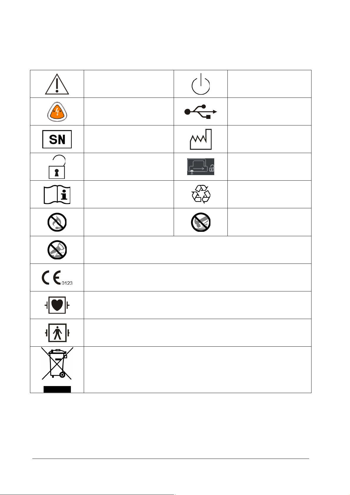
1.2 Equipment Symbols
Caution (Attention, consult
accompanying documents)
Shock button
Serial number
Unlocking
Operating instructions
Do not expose the battery to high
heat or open flames. Do not
incinerate the battery.
Stand-by
USB connector
Date of manufacture
Open the battery door as indicated
General symbol for
recovery/recyclable
Do not crush the battery.
Do not mutilate the battery or open the battery case.
Mark of conformity to European Medical Device Directive 93/42/EEC
DEFIBRILLATION-PROOF TYPE CF APPLIED PART
DEFIBRILLATION-PROOF TYPE BF APPLIED PART
Dispose of in accordance to your country’s requirements
1-4
Page 17

2 The Basics
It is important to understand that survival rates for sudden cardiac arrest are directly related to how soon victims receive
treatment. For every minute of delay, the chance of survival declines by 7% to 10%. Treatment cannot assure survival. In
some patients, the underlying problem causing the cardiac arrest is simply not survivable despite any available care.
2.1 Overview
The BeneHeart D1 (hereinafter called the equipment) is a lightweight and portable automated external defibrillator.
There are two types of configuration for the equipment: Pro and Public. Public provides only AED mode while Pro
provides two operating modes: AED and Manual Defib mode.
In AED mode, the equipment automatically analyzes the patient’s ECG rhythm and indicates whether or not a shockable
rhythm is detected. Voice prompts provide easy-to-follow instructions and patient information to guide you through the
defibrillation process. Messages and flashing buttons are also presented to reinforce the voice prompts.
In the Manual Defib mode, the operator analyzes the patient’s ECG, and, if appropriate, follows this procedure:
1. Select the Manual Defib mode, adjust the energy level if necessary;
2. Charge; and,
3. Deliver the shock.
Defibrillation is performed through multifunction electrode pads. In Manual Defib mode, you can also perform
synchronized cardioversion.
In Manual Defib mode, the equipment also provides monitoring, displaying and storing of 3-lead ECG.
The equipment can be powered by a supplied disposable battery or a smart lithium ion battery which is rechargeable
and maintenance-free. You can easily determine the remaining battery charge by viewing the battery power gauge
displayed on the screen. For rechargeable batteries, you can also check the indicator on the battery itself.
The equipment automatically stores patient data in an internal storage card. You can also export the data through the
USB port for viewing on a PC through the data management software.
2.2 Intended Use
Pro is intended for automatic defibrillation (AED) and manual defibrillation treatments. It guides operators through
Cardiopulmonary resuscitation (CPR) and can also be used for ECG monitoring.
Public is intended for AED. It also guides operators throughout CPR.
The equipment is for use in pre-hospital settings by qualified medical personnel trained in the operation of the
equipment and qualified by training in basic life support, advanced cardiac life support or defibrillation.
2-1
Page 18
2.2.1 AED
The AED mode is to be used only on cardio arrest patients who must be:
Unresponsive
Not breathing or not breathing normally
2.2.2 Manual Defibrillation
Asynchronous defibrillation is the initial treatment for ventricular fibrillation and ventricular tachycardia in patients that
are pulseless and unresponsive. Synchronous defibrillation is intended for termination of atrial fibrillation.
2.2.3 ECG
The ECG monitoring function is used to monitor and/or store the patient’s ECG waveform and heart rate.
2.3 Main Unit
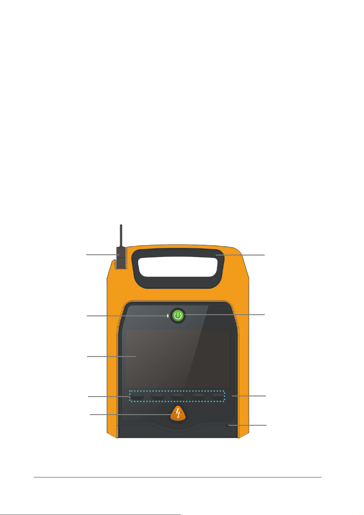
2.3.1 Front View
1
2
3
6
7
4
5
1. Pads connector
It is used to connect the multifunction electrode pads.
2-2
8
9
Page 19
2. Status indicator
Green: All the tests are passed, and the equipment operates properly.
Red: Failure is detected on the equipment.
3. Display screen
4. Soft keys
They are corresponding with the soft key labels located immediately above. The labels of the soft keys change
according to the current operating mode. For Pro, there are five soft keys while for Public, there are three.
5. Shock button
Press this button to deliver a shock to the patient.
6. Handle
7. Power ON/OFF button
Press this button to turn on or off this equipment.
8. Optical sensor
9. Microphone
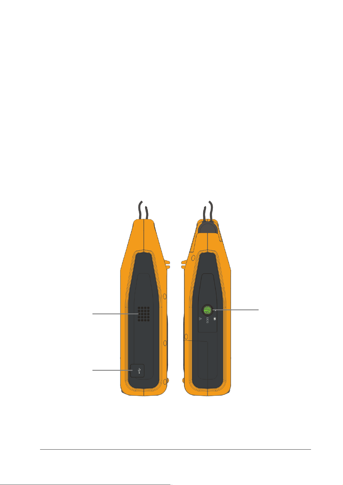
2.3.2 Side View
1
2
1. Speaker
2. USB connector
3. ECG: ECG cable connector (for Pro only)
3
2-3
Page 20
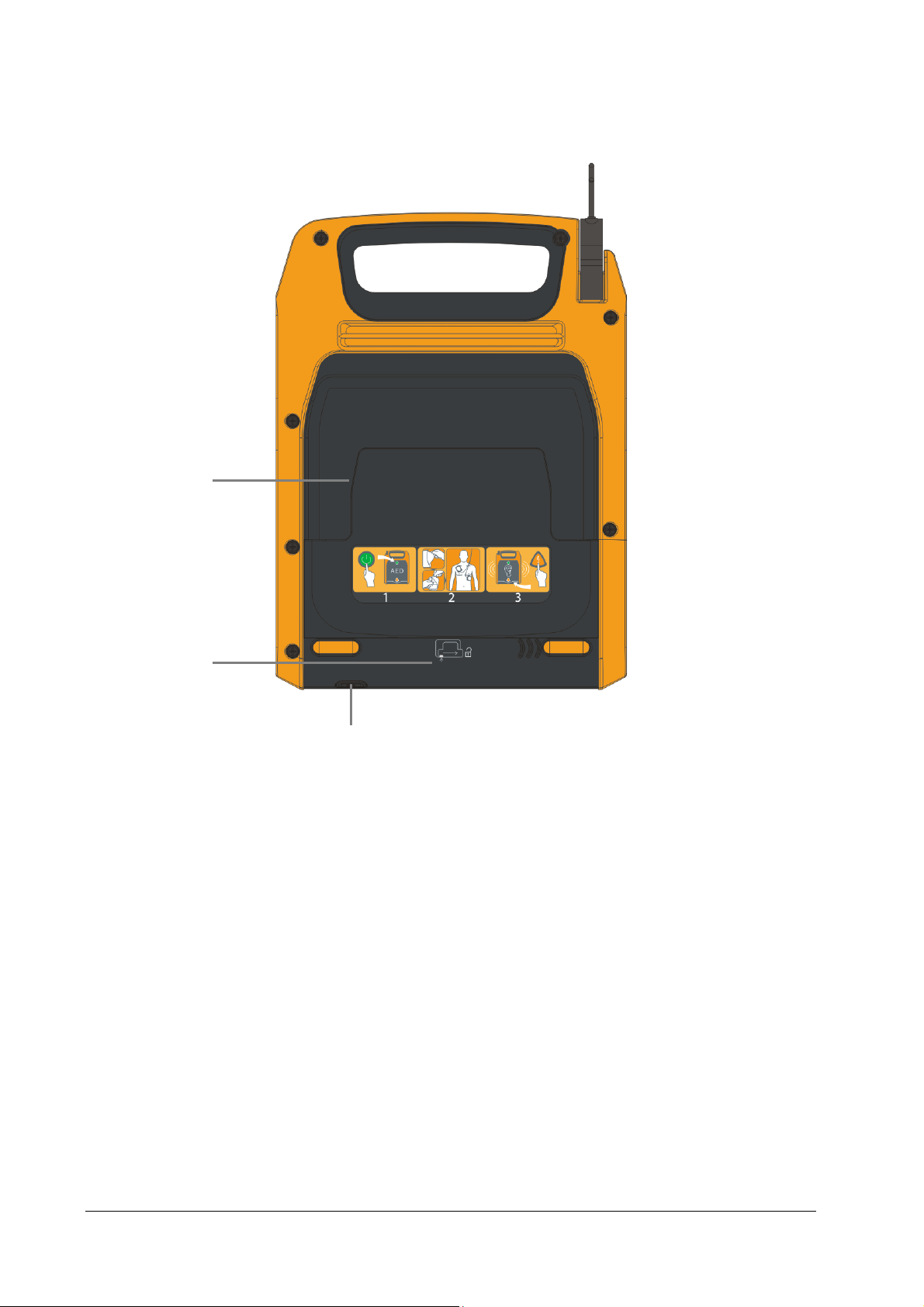
2.3.3 Rear View
1
2
1. Pads compartment
2. Battery compartment
3. Release button
Press down this button and slide the battery door to the right to open the battery compartment.
3
2-4
Page 21
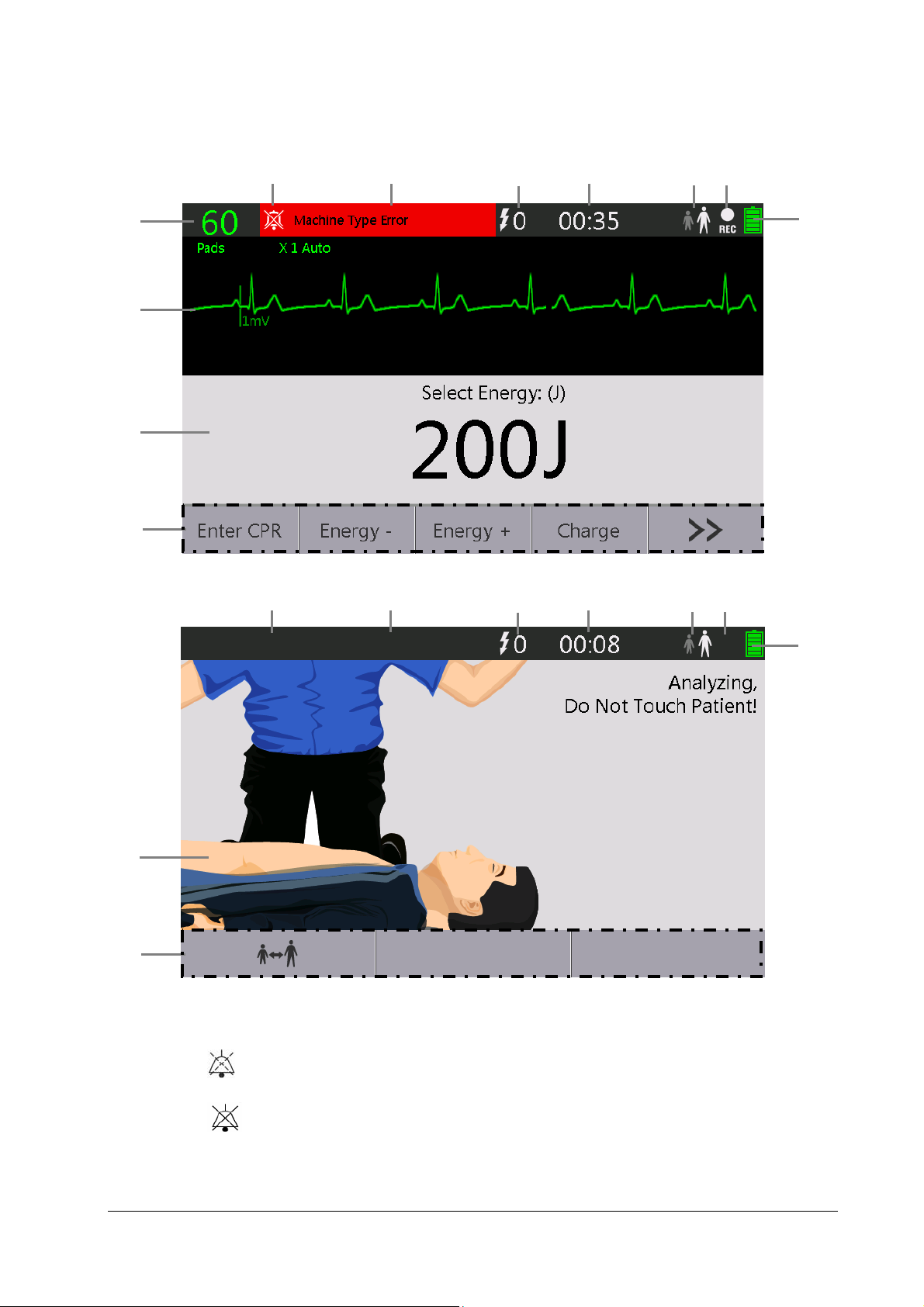
2.4 Display Views
For Pro
8
9
10
11
For Public
1
1
2
2
3
3
4
4
5 6
7
5 6
10
11
1. Alarm status symbols
indicates alarm sounds are paused;
7
indicates alarm sounds are turned off.
2. Alarm area
This area shows alarm messages. When multiple alarms occur, they will be displayed circularly.
2-5
Page 22
3. Number of delivered shocks
4. Runtime area
This area shows the equipment's operating time since it is turned on.
5. Patient type
6. Record icon
It is displayed if the sounding recording function is enabled.
7. Battery Status indicator
It indicates battery status. Refer to 10 Battery for details.
8. Heart rate
9. Waveform area
This area shows the ECG waveforms.
10. Therapy information area
11. Soft key label area
The soft key labels correspond to the soft key buttons located immediately below. The labels of the soft keys
changes according to the current display view and function. Soft key labels appearing as blank indicate that the
soft key is inactive.
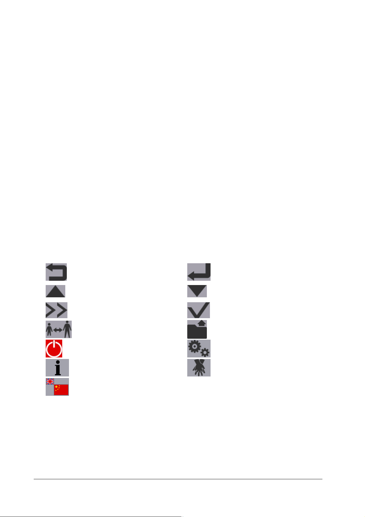
2.5 Soft Key Symbols
Below is the description of symbols displayed in the soft key label area:
Return to the previous page
Move to the previous item/page
Display more options
Switch to Adult or Pediatric mode
Power off
Show more instructions Change the compression/ventilation rate
Audio Language softkey
Switch the language of audio prompts. The symbol changes if the system language is changed. The
larger symbol indicates the current language while the smaller one indicates the target language.
This symbol is for Public only. It is displayed only when [Bilingual Option] is set to [On]
Enter/Confirm
Move to the next item/page
Confirm selection
Start archive
Maintenance
2-6
Page 23

3 Basic Operations and Settings
3.1 Installation
WARNING
The equipment shall be installed by personnel authorized by the manufacturer.
The software copyright of the equipment is solely owned by the manufacturer. No organization or
individual shall resort to juggling, copying, or exchanging it or to any other infringement on it in any form
or by any means without due permission.
Devices connected to the equipment must meet the requirements of the applicable IEC standards (e.g. IEC
60950 safety standards for information technology equipment and IEC 60601-1 safety standards for
medical electrical equipment). The system configuration must meet the requirements of the IEC 60601-1-1
medical electrical systems standard. Any personnel who connect devices to the equipment’s signal
input/output port is responsible for providing evidence that the safety certification of the devices has
been performed in accordance to the IEC 60601-1-1. If you have any question, please contact the
manufacturer.
If it is not evident from the equipment specifications whether a particular combination is hazardous, for
example, due to summation of leakage currents, consult the manufacturers or else an expert in the field, to
ensure the necessary safety of all devices concerned will not be impaired by the proposed combination.
NOTE
To ensure that the equipment is ready for any urgent use, keep it with battery installed and pads
preconnected.
3.1.1 Unpacking and Checking
Before unpacking, examine the packing case carefully for signs of damage. If any damage is detected, contact the carrier
or the manufacturer. If the packing case is intact, open the package and remove the equipment and accessories carefully.
Check all materials against the packing list and check for any mechanical damage. If you have any question, please
contact us.
WARNING
Package material may contaminate the environment. Properly dispose of the package material according
to applicable waste control regulations and keep it out of children’s reach.
The equipment might be contaminated during storage and transport. Before use, please verify whether
the packages are intact, especially the packages of single use accessories. In case of any damage, do not
apply it to patients.
3-1
Page 24

NOTE
Save the packing case and packaging material as they can be used if the equipment must be reshipped.
3.1.2 Environmental Requirements
The operating environment of the equipment must meet the requirements specified in this manual.
The environment where the equipment is used shall be reasonably free from noises, vibration, dust, corrosive,
flammable and explosive substances. If the equipment is installed in a cabinet, sufficient space in front and behind shall
be left for convenient operation, maintenance and repair. Moreover, to maintain good ventilation, the equipment shall
be at least 2 inches (5 cm) away from around the cabinet.
When the equipment is moved from one place to another, condensation may occur as a result of temperature or
humidity difference. In this case, never start the system before the condensation disappears.
NOTE
Make sure that the operating environment of the equipment meets the specific requirements. Otherwise,
unexpected consequences, e.g. damage to the equipment, could result.
3.1.3 Installing the Battery
To install the battery:
1. Press down the release button and slide the battery door to the right as indicated to remove the battery door.
2. Align the battery pins with the battery connecter, slide the battery into the battery compartment, and press until
you hear it click into the place.
3. Cover the battery door on the compartment, and slide to the left until you hear it click into the place.
NOTE
Check the expiration date displayed on the disposable battery. Remove from use if the battery is expired.
Make sure the battery door is reinstalled properly to protect the equipment and battery.
3.1.4 Connecting Electrode Pads
1. Plug the pads connector into the pads socket.
2. Place the pads package into the pads compartment properly and carefully.
3-2
Page 25

NOTE
Make sure the pads package is intact before use. Otherwise, replace it with a new one.
3.2 Basic Operations
3.2.1 Turning Power On
1. Check for mechanical damages on the equipment or other damages on the pads package.
2. Make sure the pads cable is properly connected and battery installed.
3. Check the expiration date of the pads on the pads package.
4. Press the Power ON/OFF button to start the equipment.
3.2.2 Changing General Settings
You can change the general settings in the [General Setup] menu.
To access the [General Setup] menu,
If the equipment is on, press the Power ON/OFF button and the “Select an option” window is displayed.
Then .select
If the equipment is off:
For Pro, press the Power ON/OFF button, the third and fourth soft keys (from left to right) simultaneously to
display the maintenance screen;
For Public, press the Power ON/OFF button, the second and third soft keys (from left to right)
simultaneously.
Then select [Config.]→[Config. Edit]→enter the required password→[General Setup].
→[Config.]→[Config. Edit]→enter the required password→[General Setup].
NOTE
All changes made in Configuration mode are auto-saved immediately. You can turn off the equipment
after the setting is finished.
3.2.2.1 Setting the Date and Time
1. In the [General Setup] menu, select [System Date] to set the system date.
2. Select [Time] to set the system time.
3-3
Page 26

3.2.2.2 Selecting System Language
In the [General Setup] menu, select [Language] to set the system language, which refers to the language of messages,
menus, and audio prompts and so on.
If the system language is set to a non-English language, you can also set [Bilingual Option] in the [General Setup]
menu. When [Bilingual Option] is set to [On], the text prompts in AED mode are displayed in English and the set system
language. And for Public, you can press the Audio Language softkey to switch the language of audio prompts. For
details about the softkey, refer to 2.5 Soft Key Symbols.
For Pro, [Bilingual Option] is disabled when [ECG Display] is set to [On].
3.2.2.3 Setting Default Startup Mode (For Pro Only)
For Pro, in the [General Setup] menu, select [Default Startup Mode] and set the default startup mode to:
[AED]: the equipment enters AED mode by default after startup; or,
[Manual]: the equipment enters Manual Defib mode by default after startup.
3.2.3 Turning off the Equipment
To turn off the equipment, follow this procedure:
1. Confirm that the patient monitoring or therapy is completed.
2. Disconnect the patient cables and sensors from the patient.
3. Press the Power ON/OFF button and the “Select an option” window is displayed.
4. Press the
soft key to shut down the equipment.
3.2.4 Auto Restoring to Last Configuration
During operation, you may make changes to some settings. However, these changes may not be saved as user
configuration. To prevent the changes from losing in case of sudden power failure, the equipment saves the settings in
real time. The saved settings are the latest configuration. In case of power failure, the equipment loads the latest
configuration if restarts within 60 seconds; it loads the user configuration if restarts 120 seconds later after the power
failure; it may load either the latest configuration or the user configuration if restarts between 60 and 120 seconds after
the power failure.
3.3 Post Use Procedure
After the equipment has been used on a patient, the unit shall be cleaned as described in 11 Care and Cleaning. Then
follow the procedure below to prepare the equipment for next use:
1. Connect a new pads package to the equipment as described in 3.1.4 Connecting Electrode Pads.
2. Perform a user test as described in 12.3.5 User Test. Check the test result and make sure all test items are passed.
3. Turn off the equipment.
3-4
Page 27

4 Alarms
Alarms, triggered by a vital sign that appears abnormal or by technical problems of the equipment, are indicated to the
user by visual and audible alarm indications.
WARNING
A potential hazard exists if different alarm presets are used for the same or similar device in any single
area, e.g. an intensive care unit or cardiac operating room.
4.1 Alarm Categories
By nature, Pro’s alarms can be classified into two categories: physiological alarms and technical alarms while Public
provides only technical alarms.
1. Physiological alarms
Physiological alarms, also called patient status alarms, are triggered by a monitored parameter value that violates
set alarm limits or by an abnormal patient condition. In AED mode, no physiological alarm will be presented.
2. Technical alarms
Technical alarms, also called system status alarms, are triggered by a device malfunction or a patient data distortion
due to improper operation or system failure.
Alarm messages are displayed in the alarm area.
Apart from the physiological and technical alarms, the equipment also shows some messages indicating system status.
Technically, prompt messages are not alarm messages. Messages of this kind are usually displayed in corresponding
information area. Some special prompts are shown in dialog boxes.
4.2 Alarm Levels
By severity, alarms can be classified into three categories: high level alarms, medium level alarms and low level alarms.
Physiological alarms (For Pro only) Technical alarms
High
level
Medium
level
Low
level
Indicate that your patient is in a life threatening
situation, such as Asystole, Vfib/Vtac and so forth,
and an emergency treatment is demanded.
Indicate that your patient’s vital signs appear
abnormal and an immediate treatment is required.
Indicate that you patient’s vital signs appear
abnormal and an immediate treatment may be
required.
Indicate a severe device malfunction or an improper
operation, which could make it possible that the equipment
cannot detect critical patient status or may cause therapy
failed, and thus threaten the patient’s life, such as low battery.
/
Indicate a device malfunction or an improper operation,
which may compromise a certain function but will not
threaten the patient’s life.
4-1
Page 28

4.3 Alarm Indicators
When an alarm occurs, the equipment indicates it to the user through visual or audible alarm indications.
Alarm tones
Alarm message
NOTE
When multiple alarms of different levels occur simultaneously, the equipment will select the alarm of the
highest level and give visual and audible alarm indications accordingly. Alarm messages will be displayed
circularly.
4.3.1 Audible Alarms
The equipment uses different alarm tone patterns to match the alarm level:
High level alarms triple+double+triple+double beeps.
Medium level alarms triple beeps.
Low level alarms single beep.
4.3.2 Alarm Message
When an alarm occurs, the alarm message will appear in the technical or physiological alarm area. For physiological
alarms, the asterisk symbols (*) before the alarm message match the alarm level as follows:
High level alarms ***
Medium level alarms **
Low level alarms *
Additionally, the alarm message has different background color which matches the alarm level.
High level alarms shifts fast between black text on red background and red text on white background
(in a frequency of 2 Hz)
Medium level alarms shifts slowly between black text on yellow background and yellow text on white
background (in a frequency of 0.5 Hz)
Low level alarms black text on yellow background
4.3.3 Alarm Status Symbols
Apart from the aforementioned alarm indicators, the equipment still uses the following symbols telling the alarm status:
indicates alarm sounds are turned off. You can only restore the alarm sound in configuration mode.
indicates the alarm sounds for current alarms are paused. If new alarms are triggered, alarm sounds restore
to normal.
4-2
Page 29

4.4 Alarm Tone Configuration
4.4.1 Changing the Alarm Volume
1. If the equipment is on, press the Power On/Off button and then select →[Config.→][Config. Edit→]enter
the required password→[Alarm].
2. Set [Alm Volume] to any of the following:
[High]: the alarm volume is set to the highest level.
[Med]: the alarm volume is set to a medium level.
[Low]: the alarm volume is set to a lower level.
[Off]: the alarm sound is disabled.
NOTE
The alarm volume for special system alarms is always high and not user-adjustable.
4.4.2 Pausing Alarm Sounds
You can press the [Silence] softkey to temporarily disable alarm tones. In this case, the symbol will be displayed in
the sound symbol area indicating all alarm sounds are silenced temporarily. In the audio paused status, all alarm
indicators except audible alarm tones works properly. You can press [Silence] again to restore alarm sounds.
If new alarms are triggered, alarm sounds restore to normal automatically.
NOTE
The alarm volume for special system alarms cannot be paused.
4.4.3 Switching Off Alarm Sounds
1. If the equipment is on, press the Power On/Off button and then select →[Config.→][Config. Edit→]enter
the required password→[Alarm].
2. Set [Alm Volume] to [Off] to switch off the alarm sounds.
In the audio off status, appears in the sound symbol area. In this case, all alarm indicators except audible alarm
tones works properly. To resume the alarm sounds, set [Alm Volume] to [High], [Med] or [Low].
When alarms or alarm sounds are turned off, the equipment can give a reminder tone of a single beep every 60 seconds.
The volume for reminder tone is set to a fixed level and not user-adjustable.
4-3
Page 30

4.5 Reminder Tones
When alarms or alarm sounds are turned off, the equipment can give a reminder tone of a single beep every 60 seconds.
The reminder tone is switched off by default. You can switch it on by selecting [Alarm] →[Reminder Tone] in the
[Config. Edit] menu.
4.6 Clearing Technical Alarms
For some technical alarms, their alarm message background flashing and alarm tones are cleared and the alarm
messages change to prompt messages after [Silence] soft key is pressed. After the equipment restores the normal alarm
status, it can give alarm indications correctly in case these alarms are triggered again.
For some technical alarms, all their alarm indications are cleared after [Silence] soft key is pressed. After the equipment
restores the normal alarm status, it can give alarm indications correctly in case these alarms are triggered again.
For others, their alarm tones are cleared but the alarm message background flashing and alarm messages remain after
[Silence] soft key is pressed. After the equipment restores the normal alarm status, all the alarm indications will continue
if the alarm conditions still present.
4.7 When an Alarm Occurs
When an alarm occurs, observe the following steps and take proper actions:
1. Check the patient’s condition.
2. Confirm the alarming parameter or alarm category.
3. Identify the alarm source.
4. Take proper action to eliminate the alarm condition.
5. Make sure the alarm condition is corrected.
For actions taken with regard to specific alarms, see 13 Troubleshooting.
4-4
Page 31

5 AED
5.1 Overview
This chapter describes how to operate the equipment in AED Mode. While operating in AED Mode, the equipment
analyses the patient’s ECG waveforms and guides you through the defibrillation process.
The equipment starts analyzing the patient’s heart rhythm immediately after entering AED mode. When a shockable
rhythm is detected, the equipment gives a prompt and automatically starts charging. If a shockable rhythm is not
detected, a “No shock advised” prompt is given. Smart defibrillation analysis goes through automated external
defibrillation until the equipment enters CPR or abnormal pads connection occurs.
While operating in AED Mode, the capabilities of the device are limited to those essential to the performance of
automated external defibrillation. Only ECG signals acquired through pads are displayed.
5.2 Safety
DANGER
Defibrillation current can cause operator or bystander severe injury or even death. Never touch the
patient or any equipment connected to the patient (including the bed or gurney) during defibrillation.
Avoid contact between parts of the patient’s body such as exposed skin of head or limbs, conductive fluids
such as gel, blood, or saline, and metal objects such as a bed frame or a stretcher which may provide
unwanted pathways for the defibrillating current.
Do not allow multifunction electrode pads to touch each other or to touch other ECG monitoring
electrodes, lead wires, dressings, etc. Contact with metal objects may cause electrical arcing and patient
skin burns during defibrillation and may divert current away from the heart.
To avoid explosion hazard, do not use the equipment in the presence of oxygen-rich atmospheres,
flammable anesthetics, or other flammable agents (such as gasoline). Keep the equipment and the
operating environment dry and clean.
WARNING
During defibrillation, air pockets between the skin and multifunction electrode pads can cause patient
skin burns. To help prevent air pockets, make sure defibrillation pads are completely adhered to the skin.
Do not charge and deliver shocks frequently for a long time if disposable battery is used.
Do not use dried-out pads.
5-1
Page 32

CAUTION
Aggressive handling of multifunction electrode pads in storage or prior to use can damage the pads.
Discard the pads if they become damaged.
For patients with implantable pacemaker, the sensitivity and specificity of AED algorithm may be
impaired.
NOTE
If needed, perform CPR when there is delay or interruption in using of the equipment.
5.3 AED View
A typical screen in AED Mode is shown below.
For Pro
For Public
In AED mode, the information area displays CPR instructions, pads connection instructions and AED prompt messages.
For Pro, HR numeric and one ECG waveform acquired from the multifunction electrode pads are displayed above the
information area if [ECG Display] is set to [On].
5-2
Page 33

5.4 AED Procedure
Confirm that the patient is unresponsive, not breathing or not breathing normally. Then:
1. Press the Power On/Off button to turn on the equipment.
When the equipment enters AED mode, it checks to see if the pads and pads cable are properly connected. If not,
prompt messages will appear in the AED information area until corrective action has been taken.
2. Expose the patient's chest. Wipe moisture from the patient’s chest and, if necessary, clip or shave excessive chest
hair.
3. Apply multifunction electrode pads to the patient as directed on the pads package.
RA
LL
Adult (anterior-lateral) Pediatric (anterior-posterior)
4. Follow the screen and voice prompts.
If a shockable rhythm is detected, the equipment charges automatically.
If a shockable rhythm is not detected, the system prompts "no shock advised" and then starts CPR or resume
rhythm analysis according to the current [NSA Action] setting.
5. Press the Shock button, if prompted.
Make sure no one is touching the patient, bed or any equipment connected to the patient. Call out clearly and
loudly “Stay Clear”. Then press the Shock button on the front panel to deliver a shock to the patient.
Delivery of the shock is confirmed by the voice and screen prompt "Shock Delivered" and the shock counter on the
display is updated to reflect the number of shocks given. If the configured [Shock Series] is greater than one, the
equipment resumes analyzing the patient’s rhythm after the shock is delivered to see if the shock was successful.
Voice and text prompts continue to guide you through additional shocks.
Warning
Performing CPR or otherwise handling or moving the patient during rhythm analysis can cause incorrect
or delayed analysis.
For safety reasons, some low-amplitude or low-frequency heart rhythms as well as some VT rhythms may
not be interpreted as shockable rhythms.
5-3
Page 34

NOTE
Use the defibrillator pads before the expiration date. If the pads are found expired, by checking either the
expiration date on the pads package or the alarm message displayed on the screen, replace the pads
immediately. In emergency, if there are no spare pads nearby, proceed patient treatment with the pads
and ignore pads related alarm messages.
Do not use anterior-posterior pads placement (multifunction electrode pads placed on the patient’s chest
and back) for adult patients. The AED algorithm used by the equipment has not been validated using this
placement.
Use pediatric pads for pediatric patients. If you are using adult pads for pediatric patients, select
and set the patient type to pediatric and follow the instructions on the screen to apply pads.
Motion artifact may delay analysis or affect the ECG signal resulting in an inappropriate shock or no shock
advised message. Keep the patient still during ECG rhythm analysis.
The Shock button must be pressed to deliver a shock. The equipment will not automatically deliver a
shock.
Impedance is the resistance between the defibrillator’s pads hat the defibrillator must overcome to deliver
an effective discharge of energy. The degree of impedance differs from patient to patient and is affected
by several factors including the presence of chest hair, moisture, and lotions or powders on the skin. If the
“Impedance too high. Charge removed” message appears, make sure that the patient’s skin has been
washed and dried and that any chest hair has been clipped. If the message persists, change the pads.
Most pediatric cardiac arrests are asphyxial, and the resuscitation from asphyxial arrest is best
accomplished by a combination of ventilations and chest compressions. Make sure proper CPR is
performed on the patient when waiting for defibrillation equipments or advance life support. Or follow
your local protocol.
5.5 Shock Advised
If a shockable rhythm is detected, the equipment automatically charges to the pre-configured energy level for the
current patient type. A charging tone is sounded, and the Shock button flashes when the equipment is fully charged.
Heart rhythm analysis continues while the equipment charges. If a rhythm change is detected before the shock is
delivered and a shock is no longer appropriate, the stored energy is removed internally.
If the patient type is changed or pads malfunction detected during charging, the charge will be removed.
Once you are prompted "Do Not Touch Patient! Press Shock Button", if you do not do so within 30 seconds, the
equipment disarms itself and resumes analyzing.
5-4
Page 35

5.6 No Shock Advised (NSA)
If a shockable rhythm is not detected, the equipment will tell you "No Shock Advised!".
If the [NSA Action] is set to [CPR]: the equipment enters CPR status.
If the [NSA Action] is set to [Monitor]:
The equipment continues to monitor the ECG and automatically resumes analysis if a potentially shockable rhythm
is detected. You will hear “No Shock Advised! Attend to patient”. The message "No Shock Advised!" and
“Monitoring” are shown circularly in the AED information area. You can define the frequency of these prompts by
adjusting [Voice Prompt Interval] in [Config. Edit] menu.
5.7 CPR
If [Initial CPR] is set to [On], the system enters initial CPR after startup. You can set [Initial CPR] to [On] or [Off] in
[Config. Edit] menu.
In CPR mode, voice instructions, pictures, and prompt messages needed for CPR are provided.
After the shock series, ECG analysis pauses and the equipment enters the CPR status. Analysis resumes at the completion
of CPR.
CPR mode continues for 2 minutes.
Warning
Performing CPR with pads attached on the patient might damage the pads. In this case, replace the pads.
5.7.1 CPR Metronome
The equipment provides a CPR metronome feature that can be used to encourage rescuers to perform chest
compression and ventilation at AHA/ERC recommended rate.
You can press the soft key repeatedly to change the compression/ventilation rate.
Warning
The CPR metronome sounds do not indicate information regarding the patient’s condition. Because
patient status can change in a short time, the patient should be assessed at all times. Do not perform CPR
on a patient who is responsive or is breathing normally.
5-5
Page 36

5.8 AED Sound Recording
The equipment includes a sound recording function that can record the voice information during AED therapy. The
sound recording function can be configured on or off.
To switch on or off the sounding recording,
1. Press the Power On/Off button and then select
2. Select [General Setup→] [Voice Recording], and toggle between [On] and [Off].
The symbol is shown at the top right corner of the screen if the sounding recording function is enabled.
The equipment can store up to 180 minutes of recording, and one recording for one patient.
→
[Config.]→[Config. Edit]→Enter the required password.
5.9 AED Setup
→
1. Press the Power On/Off button and then select
2. Select [AED Setup >>] to enter the AED Setup menu, and then change AED settings as desired.
Refer to Section 9 Configuration Management for details.
[Config.]→[Config. Edit]→Enter the required password.
5-6
Page 37

6 Manual Defibrillation (For Pro Only)
6.1 Overview
Manual defibrillation is available only on Pro. This chapter explains how to prepare for and perform asynchronous
defibrillation and synchronous cardioversion using multifunction electrode pads.
In Manual Defibrillation Mode, you must assess the ECG waveforms, decide if defibrillation or cardioversion is indicated,
select appropriate energy setting, charge the equipment, and deliver the shock. Text messages on the screen provide
relevant information to guide your throughout the defibrillation process.
6.2 Safety
DANGER
Defibrillation current can cause operator or bystander severe injury or even death. Never touch the
patient or any equipment connected to the patient (including the bed or gurney) during defibrillation.
Avoid contact between parts of the patient’s body such as exposed skin of head or limbs, conductive fluids
such as gel, blood, or saline, and metal objects such as a bed frame or a stretcher which may provide
unwanted pathways for the defibrillating current.
Do not allow multifunction electrode pads to touch each other or to touch other ECG monitoring
electrodes, lead wires, dressings, etc. Contact with metal objects may cause electrical arcing and patient
skin burns during defibrillation and may divert current away from the heart.
During manual defibrillation, make sure your hands are dry and free from conductive gel to avoid shock
hazard.
Use care when operating this equipment close to oxygen sources (such as bag-valve-mask devices or
ventilator tubing). Turn off gas source or move source away from patient during defibrillation. This can
cause an explosion hazard.
WARNING
Do not use conductive liquid. Use only conductive gel specified by the equipment manufacturer.
Do not charge and deliver shock frequently for an long time if disposable battery is used.
Clinicians must select an appropriate energy level for defibrillation of pediatric patients.
Performing CPR with pads attached on the patient might damage the pads. In this case, replace the pads.
6-1
Page 38

CAUTION
Prior to using this defibrillator, disconnect from the patient all equipment that is not
defibrillator-protected.
NOTE
Impedance is the resistance between the defibrillator’s pads that the defibrillator must overcome to
deliver an effective discharge of energy. The degree of impedance differs from patient to patient and is
affected by several factors including the presence of chest hair, moisture, and lotions or powders on the
skin. If the “Impedance too high. Shock Removed” message appears, make sure that the patient’s skin has
been washed and dried and that any chest hair has been clipped. If the message persists, change the pads.
6.3 Manual Defibrillation View
A typical screen in Manual Defib mode is shown below.
In manual defibrillation mode, an ECG waveform and related parameters are displayed. In the middle of the screen,
synchronous icon, prompt message, selected energy, and a shock counter are displayed.
In manual defibrillation mode, you can perform the following operations:
Press [Enter CPR] soft key to enter CPR mode.
Press [Energy -] or [Energy +] soft keys to adjust the energy for defibrillation shock. You can accelerate the
selection by pressing and holding either of the buttons. If pads are not properly connected, the two soft keys are
disabled.
Press [Charge] soft key to charge.
Press [>>] soft key to display more options.
Press [AED] soft key to enter AED mode.
Press [Lead] soft key to select leads.
Press [Gain] soft key to adjust the gain of waveform.
6-2
Page 39

Press [Enter Sync] soft key to enter synchronous cardioversion mode.
Press
Press [Silence] to temporarily pause the current alarm sound. This soft key is not displayed if there is no alarm
sound currently.
soft key to change patient type.
6.4 Manual Defibrillation Procedure
1. Expose the patient’s chest. Wipe moisture from the patient’s chest and, if necessary, clip or shave excessive chest
hair.
2. Connect pads cable to the pads interface. If pre-connected, skip this step.
3. Apply pads to the patient according to the instructions for use indicated on pads package.
4. Turn on the equipment and enter Manual Defib mode.
You can set the [Default Startup Mode] to [AED] or [Manual] in the [Config. Edit] menu. The default setting is
[AED].
If [Default Startup Mode] is set to [AED], the equipment enters AED mode after startup. You can select
[Manual]→[Yes] to enter manual defibrillation mode.
If [Default Startup Mode] is set to [Manual], the equipment enters manual defibrillation mode directly after
startup.
5. Press [Energy -] or [Energy +] soft keys to adjust the energy for defibrillation shock.
You can accelerate the selection by pressing and holding either of the buttons.
6. Press [Charge] soft key to charge.
As the equipment charges, a progress bar is shown in the defibrillation information area. A charging tone sounds
until desired energy level is reached, when you will hear a charge done tone.
If you have to increase or decrease the selected energy during charging or after charging is complete, press
[Energy -] or [Energy +] soft keys to select the desired energy level as explained above. Then press the charge
button again to restart charging.
To remove the energy, press the [Disarm] soft key. If the Shock button is not pressed within 60s, the equipment
disarms automatically.
7. Shock.
Confirm that a shock is still indicated and that the equipment has charged to the selected energy level. Make sure
no one is touching the patient, bed or any equipment connected to the patient. Call out loudly and clearly, “Stay
Clear!” and then press the Shock button to deliver energy.
NOTE
For defibrillation of adult patients, recommended energy level is 200 Joules.
Use pediatric pads for pediatric patients. If you are using adult pads for pediatric patients, select
and set the patient type to pediatric and follow the instructions on the screen to apply pads.
6-3
Page 40

6.5 Synchronized Cardioversion
Synchronized Cardioversion allows you to synchronize delivery of the defibrillator shock with the R-wave of the ECG.
To use synchronized cardioversion, press the [>>] and then [Enter Sync] soft keys in the Manual Defib mode. Then “Sync”
appears in the Defibrillation information area and a marker appears above each R-wave, see the figure below:
You can monitor ECG through multifunction electric pads or electrodes connected to a 3-lead ECG cable. Shock is
delivered through pads.
For synchronized cardioversion, we recommend to acquire patient’s ECG through ECG lead set.
6.5.1 Performing Synchronized Cardioversion
1. Connect the pads cable and apply the pads to the patient. If ECG set is used for ECG monitoring, connect the ECG
cable and apply the ECG electrodes to the patient, referring to 7 Monitoring ECG.
2. In Manual Defib mode, press the [>>] and then [Enter Sync] soft keys to activate the synchronous cardioversion
function.
3. Press the [>>] and then [Lead] soft keys to select a lead. The selected lead should have a clear signal and a large
QRS complex.
4. Verify that a white R-wave marker appears above each R-wave. If the R-wave markers do not appear or do not
coincide with the R-waves, for example above the T-waves, select another lead.
5. Verify that the equipment enters the Sync mode, as indicated by the SYNC mark shown in the defibrillation
information area.
6. Press [Energy -] or [Energy +] soft keys to a desired energy level.
7. Press [Charge] soft key to charge.
8. Confirm that a shock is still indicated and that the equipment has charged to the selected energy level. Make sure
no one is touching the patient, bed or any equipment connected to the patient. Call out loudly and clearly, “Stay
Clear!”.
9. Press and hold the Shock button on the equipment. The shock will be delivered when the next R-wave is detected.
6-4
Page 41

NOTE
Once the equipment enters Synchronized Cardioversion mode, the alarms resume.
During synchronized cardioversion, it is important to continue to hold the shock button until the shock is
delivered. The equipment shocks with the next detected R-wave.
If no R-wave is detected within 9s, a prompt message "'No R-Wave" is displayed.
6.5.2 Delivering Additional Synchronized Shocks
If additional synchronized shocks are indicated, perform the following steps:
1. Make sure the equipment is still in Sync mode, as indicated by the presence of the Sync message in the
defibrillation information area.
2. Repeat Steps 4 to 9 as described above.
If [Sync after Shock] is set to [Yes ], the equipment remains in the sync mode after a shock is delivered; if set to [No], the
equipment exits the sync mode and enters the asynchronous defibrillation mode after a shock.
6.5.3 Disabling the Sync Function
To switch off the Sync function, press the [Exit Sync] soft key to enter the Manual Defib mode.
6-5
Page 42

FOR YOUR NOTES
6-6
Page 43

7 Monitoring ECG (For Pro Only)
7.1 Overview
The electrocardiogram (ECG) measures the electrical activity of the heart and displays it as waveforms and numerics. The
equipment enables ECG monitoring through 3-lead ECG sets and multifunction electrode pads. If both ECG sets and
pads are connected, the configured ECG waveform is displayed in the waveform area.
ECG monitoring is available only on Pro.
7.2 Safety
WARNING
Periodically inspect the electrode application site to ensure skin quality. If the skin quality changes,
replace the electrodes or change the application site.
Use defibrillation-proof ECG cables during defibrillation.
When monitoring a patient implanted with a pacemaker, do not completely rely on the heart rate reading
or the heart rate alarms. Always keep paced patients under close surveillance.
NOTE
If the correct electrodes are applied properly to the patient as instructed by the manufacturer, the display
recovers in 10s after defibrillation.
When connecting electrodes and/or patient cables, make sure that the connectors never come into contact
with other conductive parts, or with earth. Particularly make sure that all of the ECG electrodes are
attached to the patient.
Interference from a non-grounded instrument near the patient and electrosurgery interference may cause
problems with the waveform.
If selected lead cannot provide valid ECG signals, a dash line is shown in the ECG waveform area.
Use the same type of ECG electrodes when monitoring ECG through ECG lead set.
7-1
Page 44

7.3 ECG View
Heartbeat
icon
Lead
ECG monitoring is provided after startup in both AED and Manual Defibrillation mode. The equipment displays one ECG
waveform and the heart rate reading.
If the patient is properly connected to the equipment, a dash line is shown in the ECG waveform area.
HR value
Gain
7.4 Preparing to Monitor ECG
7.4.1 ECG Monitoring with Electrodes
1. Prepare the patient’s skin. Proper skin preparation is necessary for good signal quality at the electrode, as the skin is
a poor conductor of electricity. To properly prepare the skin, choose flat areas and then follow this procedure:
Shave hair from skin at chosen sites.
Gently rub skin surface at application sites to remove dead skin cells.
Thoroughly clean the sites with mild soap and water. We do not recommend using ether or pure alcohol,
because this dries the skin and increases the resistance.
Dry the skin completely before applying the electrodes.
2. Attach the clips or snaps to the electrodes before placing them.
3. Place the electrodes on the patient.
4. Attach the lead wires to the ECG trunk cable.
5. Plug the trunk cable into the equipment’s ECG connector.
7.4.1.1 Placing Electrodes
3-Lead Placement
The following is a typical AHA electrode placement for a 3-lead ECG set:
RA placement: directly below the clavicle and near the right shoulder.
LA placement: directly below the clavicle and near the left shoulder.
LL placement: on the left lower abdomen.
7-2
Page 45

Electrode Placement for Surgical Patients
The surgical site should be taken into consideration when placing electrodes on a surgical patient, e.g. for open-chest
surgery, the chest electrodes can be placed on the lateral chest or back. To reduce artifacts and interference from
electrosurgical units, you can place the limb electrodes close to the shoulders and lower abdomen and the chest
electrodes on the left side of the mid-chest. Do not place the electrodes on the upper arm. Otherwise, the ECG
waveform will be very small.
WARNING
When using electrosurgical units (ESU), place ECG electrodes between the ESU and its grounding plate to
prevent unwanted burns. Never entangle ESU cable and ECG cable together.
When using electrosurgical units (ESU), never place ECG electrodes near to the grounding plate of the ESU,
as this can cause a lot of interference on the ECG signal.
7.4.2 ECG Monitoring with Pads
1. Prepare the patient’s skin.
2. Apply pads according to the instructions for use indicated on pads package. Use anterior-lateral placement.
3. Connect the pads cable with the equipment if not pre-connected.
Pads placement for Adult Patient
1. Place the RA pad on the patient’s upper right torso, lateral to the sternum and below the clavicle, as shown below.
2. Place the LL pad to the patient’s left nipple in the midaxillary line, with the center of the electrode in the midaxillary
line, if possible. See the figure below.
RA
LL
7-3
Page 46

Pads Placement for Pediatric Patient
Place the pink pad in the center of the chest between the nipples, and the yellow one in the center of the back
(anterior-posterior), as shown below:
7.5 Changing ECG Settings
7.5.1 Selecting Lead Type
In Manual Defibrillation mode, select [>>] and then press [Lead] repeatedly to set lead type as per the adopted lead
type.
7.5.2 Setting Gain
If the wave is too small or clipped, you can select [>>] and then press [Gain] repeatedly in Manual Defibrillation mode to
change its size.
There are altogether 7 options, namely [Auto], [0.125], [0.25], [0.5], [1], [2] and [4]. When [Gain] is set to [Auto],
the system selects the most appropriate gain for the current waveform.
7.5.3 Choosing AHA or IEC Lead Placement
→
1. Press the Power On/Off button, and then select
2. In the [Config. Edit] menu, select [ECG Setup→][ECG Standard], and then select [AHA] or [IEC] according to the
standard that is applied to your hospital.
[Config.]→[Config. Edit]→enter the required password.
7.5.4 Setting Filter Mode
When monitoring ECG through ECG lead set, filter mode is displayed above the ECG waveform. To change the filter
mode:
1. Press the Power On/Off button, and then select
2. In the [Config. Edit] menu, select [ECG Setup→][ECG Bandwidth], and then select [Therapy] or [Monitor].
→
[Config.]→[Config. Edit]→enter the required password.
7-4
Page 47

7.6 Arrhythmia Analysis
Arrhythmia analysis provides information about your patient’s condition, including heart rate and arrhythmia alarms.
In the process of ECG monitoring, if any arrhythmia event is detected, corresponding arrhythmia alarms are reported
according to the alarm level.
NOTE
Arrhythmia analysis program is intended to detect ventricular arrhythmias. It is not designed to detect
atrial or supraventricular arrhythmias. It may incorrectly identify the presence or absence of an
arrhythmia. Therefore, a physician must analyze the arrhythmia information with other clinical findings.
7.6.1 Understanding the Arrhythmia Events
Arrhythmia event Description Category
Asystole No QRS complex for 4 consecutive seconds (in absence of ventricular fibrillation
or chaotic signals).
Shockable rhythum A fibrillatory wave for 4 consecutive seconds.
A dominant rhythm of adjacent Vs and a HR > the V-Tach Heart Rate Limit.
Vtac The consecutive PVCs ≥ Vtac PVCs limit, and the HR ≥ the Vtac rate limit.
Vent. Brady The consecutive PVCs ≥ the Vbrd threshold and the ventricular HR < the Vbrd
Rate threshold.
Extreme Tachy The heart rate is equal to or greater than the extreme tachycardia limit.
Extreme Brady The heart rate is equal to or less than the extreme bradycardia limit.
PVCs/min PVCs/min exceeds high limit Nonlethal
PNP No pace pulse detected for 1.75 x average R-to-R intervals following a QRS
complex (for paced patients only).
PNC No QRS complex detected for 300 milliseconds following a pace pulse (for
paced patients only).
PVC One PVC detected in normal heartbeats.
Couplet Paired PVCs are detected.
VT>2 More than 2 consecutive PVCs within the last minute.
Bigeminy A dominant rhythm of N, V,N, V, N, V.
Trigeminy A dominant rhythm of N, N, V,N, N, V, N, N, V.
R ON T R on T detected in normal heartbeats.
Brady The average heart rate is equal to or less than 60 bpm.
Tachy The average heart rate is equal to or greater than 100 bpm.
Vent. Rhythm The consecutive PVCs ≥ the Vbrd PVCs limit, and the HR is ≥ Vbrd Rate limit but
< the Vtac Rate limit.
Multif. PVC Multiform PVCs detected in Multif. PVC's Window (which is adjustable).
Lethal
arrhythmia
arrhythmia
7-5
Page 48

Arrhythmia event Description Category
Nonsus. Vtac The consecutive PVCs < the Vtac PVCs limit but > 2, and HR ≥ the Vtac Rate
limit.
Irr. Rhythm Consistently irregular rhythm.
When multifunctional electrode pads are used for ECG monitoring, the equipment provides only asystole and
shockable rhythm alarms.
7.6.2 Setting Arrhythmia Analysis
To switch arrhythmia analysis on or off:
→
1. Press the Power On/Off button, and then select
2. In the [Config. Edit] menu, select [ECG Setup] and set [Arrhythmia] to:
[Lethal Arrh. Only]: the system provides arrhythmia analysis only for lethal arrhythmia events; or,
[All]: the system provides arrhythmia analysis for all the arrhythmia events.
[Config.]→[Config. Edit]→enter the required password.
7.6.3 Changing Arrhythmia Threshold Settings
→
1. Press the Power On/Off button, and then select
2. In the [Config. Edit] menu, select [ECG Setup] and then change the arrhythmia threshold settings.
In case an arrhythmia violates its threshold, an alarm will be triggered. The setting of Asystole Delay is linked to ARR
relearning. When HR is less than 30 bpm, it is recommended to set Asystole Delay to 10 seconds.
Arrh. event Range Default Step Unit
Asystole. Delay 3 to 10 5 1 s
Extreme Tachy 60 to 300 Adult: 160
Extreme Brady 15 to 120 Adult: 35
Vbrd Rate 15 to 60 40 5 bpm
Vbrd PVCs 3 to 99 5 1 Beats
V-Tach Rate 100 to 200 130 5 bpm
V-Tach PVCs 3 to 12 6 1 Beats
Tachy 60 to 300 Adult: 120
Brady 15 to 120 Adult: 50
Multif. PVCs Window 3 to 31 15 1 Beats
PVCs High 1 to 100 10 1 /
[Config.]→[Config. Edit]→enter the required password.
5 bpm
Pediatric: 180
5 bpm
Pediatric: 50
5 bpm
Pediatric: 160
5 bpm
Pediatric: 75
7-6
Page 49

7.6.4 Automatic Arrhythmia Relearn
Arrhythmia relearning is initiated automatically whenever:
The ECG lead or lead label is changed
The ECG lead is re-connected
Patient category is changed
The paced status is changed,
Arrhythmia analysis is switched on
[Stop Calibrating] is selected after ECG calibration is completed.
NOTE
Arrhythmia relearning in the case of ventricular tachycardia may affect correct arrhythmia alarm.
7-7
Page 50

FOR YOUR NOTES
7-8
Page 51

8 Data Management
8.1 Introduction
Once turned on, the equipment automatically generates a patient ID and starts to record the following information for
the current patient:
Trends,
Waveforms,
Events; and,
Audio recording of the rescuing process (for up to three hours).
Along with the above patient data, some device information is also exported, including intellectual property statement,
device ID, software version, hardware version, work status, and battery information.
The data management function enables you to export the following patient data on the equipment to a USB flash
memory:
[Latest]: the latest patient document;
[Unexported]: all the documents that have never been exported; and
[All]: all the patient documents saved on the equipment.
NOTE
It is recommended to export patient data after each use. Or earlier-stored data might be overwritten by
later ones.
8.2 Recommended USB Flash Memory
Brand Model Size of Memory
Kingston DataTraveler 108 8 GB
Sandisk CZ50 4 GB
8 GB
8-1
Page 52

8.3 Exporting Data
1. Plug a USB flash memory to the USB connector on the equipment.
2. Press the Power On/Off button, and then select
3. Select the [Archive] soft key, and press
to confirm the selection.
4. Press to start export. The equipment automatically searches for USB flash memory and once succeeds, starts
to export data.
5. Remove the USB flash memory after the data has been exported.
or to toggle among the data to be exported, and then
to enter the maintenance mode.
CAUTION
To avoid shock hazard, do not connect the USB flash memory unless you are to export data. Remove it
timely once finished.
NOTE
If [Delete Data After Exporting] is selected before export, the exported data will be delected from the
equipment when export is completed
During data export, the message “Exporting Data. Please Wait...” appears above the soft key area. If an exception
happens, data export stops automatically and the reason for interruption is presented in the prompt information area.
NOTE
Do not remove the USB flash memory from the equipment before data is completely exported.
8-2
Page 53

9 Configuration Management
9.1 Introduction
Configurations management enables you to customize you equipment to best meet your needs. With this function, you
can:
View system configuration;
Change system configuration;
Restore the factory default configuration; and,
Export or import configuration files.
After the system configurations have been changed, the new configuration settings take effect immediately.
9.2 Viewing System Configuration
When the equipment is on, press the Power On/Off button and then select →[Config.]→[View Config] to view
the current system configuration.
9.3 Password
Accessing configuration management is password protected. The required password is set to 3156 before the
equipment leaves the factory.
9.4 Accessing Configuration Management
1. Press the Power On/Off button and then select →[Config.]→[Config. Edit], and a dialog box pops up:
To access the [Config. Edit] menu, enter the correct password and the following screen is displayed (taking
Pro as example).
To close the dialog box and return to maintenance screen, select [Cancel].
9-1
Page 54

2. On the [Config. Edit] screen, you can:
Press or to toggle among setting items or options; and,
Press to confirm the selection or to return to the previous menu.
NOTE
Changing of setup items shall be performed under the direction of authorized personnel.
9.5 Restoring Factory Default Configuration
1. On the [Config. Edit] screen, press or and then to select [Config.]
2. Select [Default Config.] and the following dialog box pops up:
3. Select [Yes] to restore all the current settings to factory default settings.
WARNING
The system date, time, and language settings in [General Setup] menu and all the settings in [Network
Setup] remain unchanged after restoring factory default settings.
9.6 List of Configuration Items
Below is a list of all the configuration items in the [Config. Edit] menu. Those marked with “*” are for Pro only.
9.6.1 General Setup Menu
Menu Item Options/Range Default Remark
System Date
Year 2007 to 2099 2007
Month 01 to 12 01
Day 01 to 31 01
The selectable range for system date is
2007-01-01 to 2099-05-31.
Time
Hour 0 to 23 01
/ Minute 0 to 59 01
Second 0 to 59 01
9-2
Page 55

Menu Item Options/Range Default Remark
Three languages are available on your
equipment, CHINESE, ENGLISH, and your
local language. For English or Chinese
speaking countries, the default language
options are CHINESE, ENGLISH, and FRENCH.
Language
ENGLISH, SIM. CHINESE, FRENCH,
GERMAN, ITALIAN, SPANISH,
PORTUGUESE, RUSSIAN, CZECH,
DUTCH, CROATIA
/
Bilingual Option On, Off On
Default Startup Mode* AED, Manual AED /
Voice Recording On, Off Off /
Voice Volume Auto, High, Low Auto /
Brightness Auto, Outdoor Mode, Indoor mode Auto /
Disabled when [ECG Display] is set to [On]*
9.6.2 AED Setup Menu
Menu Item Options/Range Default Remark
Shock Series 1, 2, 3 1 /
Energy 1
Energy 2
Energy 3
NSA Action Monitor, CPR CPR /
Voice Prompt Interval Off, 30s, 60s, 90s, 120s, 150s, 180s 30s /
Initial CPR* On, Off Off
ECG Display* On, Off On
Adult 100, 150, 170, 200, 300, 360J 200 J
≤Energy 2
Pediatric 10, 15, 20, 30, 50, 70, 100J 50J
Adult Energy 1 to 360J 300 J
Cannot be less than Energy 1
Pediatric Energy 1 to 100J 70
Adult Energy 2 to 360J 360 J
Cannot be less than Energy 2
Pediatric Energy 2 to 100J 100J
When set to [On], the system enters
CPR mode directly after startup.
When set to [On], the [Bilingual
Option] setting is disabled.
9.6.3 Manual Defib Setup Menu (For Pro Only)
Menu Item Options/Range Default
Default Energy for Adult 100J, 150J, 170J, 200J, 300J, 360J 200J
Default Energy for Pediatric 10J, 15J, 20J, 30J, 50J, 70J, 100J 50J
Sync After Shock Yes, No No
9-3
Page 56

9.6.4 CPR Setup Menu
Menu Item Options/Range Default
CPR Mode 30:2, 15:2, Hands-Only 30:2
9.6.5 ECG Setup Menu (For Pro Only)
Menu Item Options/Range Default
ECG Bandwidth Monitor, Therapy Therapy
Arrhythmia Lethal Arrh. Only, All Lethal Arrh. Only
Asystole Delay 3 to 10 5
Extreme Tachy
Extreme Brady
Vbrd Rate 15 to 60 40
Vbrd PVCs 3 to 99 5
V-Tach Rate 100 to 200 130
V-tach PVCs 3 to 99 6
Tachy
Brady
Multif. PVCs Window 3 to 31 15
PVCs High 1 to 100 10
ECG Standard AHA, IEC AHA
Pacemaker Detection On, Off Off
Adult 60 to 300 160
Pediatric 60 to 300 180
Adult 15 to 120 35
Pediatric 15 to 120 50
Adult 60 to 300 120
Pediatric 60 to 300 160
Adult 15 to 120 50
Pediatric 15 to 120 75
9.6.6 Alarm Setup Menu (For Pro Only)
Menu Item Options/Range Default
Alarm Volume High, Med, Low, Off Low
Reminder Tone On, Off Off
9.6.7 Test Setup Menu
Menu Item Options/Range Default
User Test Setup 00:00, 01:00, 02:00, 03:00, 04:00, 05:00, 03:00,
9-4
Page 57

9.6.8 Network Setup Menu
Menu Item Options/Range Default Remark
IP Address
Subnet Mask /
Gateway /
Access Point
Password
Device Management System
Site
Network Test / /
4 segments, and editable range 0 to 255
for each
0 to 9, a to z, A to Z / /
4 segments, and editable range 0 to 255
for each
/
/
Input static IP address
Input the IP address of Device
Management System
Used to test the configured network
and display related connection
information
9.6.9 Config. Menu
Menu Item Remark
Default Config. Select to restore factory default setting
Config. Import Select to import an existing configuration file
Config. Export Select to export the current configuration as configuration file
9-5
Page 58

FOR YOUR NOTES
9-6
Page 59

10 Battery
10.1 Introduction
The equipment is designed to operate on battery power. There are two types of batteries supplied, rechargeable and
disposable respectively. We recommend you to check the remaining battery charge periodically to ensure enough
power for defibrillation at any time.
The equipment is configured with one battery which is free of maintenance.
On-screen battery symbol indicates the current battery status:
Indicates that the battery has low charge level and needs to be replaced.
You can check the status of rechargeable battery by pressing the fuel gauge button on the battery to illuminate the
battery gauge. The fuel gauge consisting of 5 LEDs, each LED represents a charge of approximately 20% of capacity.
If the battery charge is too low, a technical alarm will be triggered and the “Low Battery” message displayed in the alarm
area. At this moment, change the battery.
Indicates that battery works correctly. The solid green portion represents the current battery charge level.
Each block represent a charge of approximately 20% capacity.
Indicates that the battery is almost depleted and needs to be replaced immediately.
WARNING
Keep the batteries out of children’s reach.
Use only specified batteries.
The batteries should only be charged in Mindray BatteryFeed20 charger station.
Never charge the disposable battery in any case.
NOTE
Remote upgrade might take a long time and greatly reduce the charge of the installed battery. Please
check the battery status after each upgrade.
After long term use, the power charge indicated by the battery symbol may be different from the actual
charge. Always observe the alarm information displayed on the screen.
10-1
Page 60

10.2 Battery Alarms
10.2.1 Low Battery Alarm
If the battery charge is low, a technical alarm “Low Battery” will be triggered. In this case, replace the battery with a fully
charged rechargeable battery or a new disposable battery on immediately.
If the battery is almost depleted, a prompt “Battery Depleted! Replace Battery Now.” pops up and alarm tones are
provided. In this case, replace the battery immediately. This prompt will not disappear until the battery is replaced. The
equipment automatically shuts down if no action is taken in 3 minutes.
NOTE
The Low Battery alarm means that the battery is beginning to weaken and should be replaced at the first
opportunity. At least 20 minutes of monitoring and 10 200J shocks can be performed when the Low
Battery alarm is activated. Replace the battery as soon as possible.
10.2.2 Battery Aged Alarm
If the battery runtime is significantly shorter than the specification, a low level technological alarm “Battery Aged” will be
presented. We recommend you to contact our company and replace it with a new one.
10.2.3 Battery Error Alarm
In the situation that the battery has a failure, a high level technological alarm “Battery Err” will be presented. In this case,
replace the battery or contact your service personnel.
10-2
Page 61

10.3 Replacing Batteries
If the battery is depleted or malfunction is detected, you need to replace the battery. Follow the procedure below:
1. Press down the release button and slide the battery door to the right as indicated to remove the battery door.
2. Pinch the latch on the battery with strength, slide the battery rightward, and lift the battery as indicated below:
3. Make sure the battery to be installed is intact. For rechargeable batteries, make sure the charge is sufficient for use.
4. Align the battery pins, slide the battery into the battery compartment, and press until you hear it click into the
place.
5. Cover the battery door on the compartment, and slide to the left until you hear it click into the place.
NOTE
Check the expiration date displayed on the disposable battery. Remove from use if the battery is expired.
Never remove the battery unless the equipment indicates to do so.
Make sure the battery door is reinstalled properly to protect the equipment and battery.
10.4 Charging Batteries
The rechargeable batteries can be charged only using Mindray BatteryFeed20 charger station. At a temperature of 25°C
(77 °F), a completely discharged battery charges to 90% of its capacity in approximately 2.5 hours, and to 100% of its
capacity in approximately 3 hours.
Batteries should be charged at temperatures between 0 °C (32 °F) to 45 °C (113 °F). To optimize performance, a fully (or
nearly fully) discharged battery should be charged as soon as possible.
For details about the charging of rechargeable batteries, refer to the Instructions for Use of BatteryFeed20 (P/N:
H-046-001947-00).
10-3
Page 62

10.5 Storing Batteries
When storing batteries, make sure that the battery terminals do not come into contact with metallic objects. If batteries
are stored for an extended period of time, they should be placed in a cool place with a partial charge of 40% to 60%
capacity (3 LEDs illuminated for rechargeable batteries). Storing batteries in a cool place slows the aging process. The
idea storage temperature is 15 °C (60 °F). Batteries should not be stored at temperature outside the range of -20°C (-4 °F)
to 60 °C (140 °F).
NOTE
Storing batteries at temperature above 38 °C (100 °F) for an extended period of time significantly shorten
the life expectancy of a battery.
10.6 Recycling the Batteries
A battery should be discarded if there are visual signs of damage, the battery fails, the battery aged alarm is presented,
the disposable batteries has been used for more than four years, or the rechargeable batteries been used for over two
years. Properly dispose of batteries according to local regulations.
WARNING
Do not disassemble, puncture or incinerate batteries. Do not short the battery terminals. They may ignite,
explode, or leak, causing personal injury.
10-4
Page 63

11 Care and Cleaning
Use only the substances approved by the equipment manufacturer and methods listed in this chapter to clean or
disinfect your equipment. Warranty does not cover damages caused by unapproved cleaning and disinfection
substances or methods.
We make no claims regarding the efficacy of the listed chemicals or methods as a means for controlling infection. For the
method to control infection, consult your hospital’s infection control officer or epidemiologist.
In this chapter we only describe cleaning and disinfection of the main unit. For the cleaning and disinfection of reusable
accessories, refer to instructions for use of corresponding accessories.
11.1 General Points
Keep you equipment and accessories free of dust and dirt. To avoid damage to the equipment, follow these rules:
Always dilute according the manufacturer’s instructions or use lowest possible concentration.
Do not immerse part of the equipment into liquid.
Do not pour liquid onto the equipment or accessories.
Do not allow liquid to enter the case.
Never use abrasive materials (such as steel wool or silver polish), or erosive cleaners (such as acetone or
acetone-based cleaners).
WARNING
Be sure to shut down the system and remove the battery before cleaning the equipment.
CAUTION
Contact your service personnel in case of spilling liquid on the equipment or accessories.
NOTE
To clean or disinfect reusable accessories, refer to the instructions for use delivered with the accessories.
11-1
Page 64

11.2 Cleaning
Your equipment should be cleaned on a regular basis. If there is heavy pollution or lots of dust and sand in your place,
the equipment should be cleaned more frequently. Before cleaning the equipment, consult your hospital’s regulations
for cleaning the equipment.
Recommended cleaning agents are:
sodium hypochlorite bleach (diluted)
Hydrogen peroxide (3%)
Isopropanol (70%)
Ethanol (70%)
To clean your equipment, follow these rules:
1. Shut down the equipment, disconnect cables, and remove the battery.
2. Clean the display screen using a soft, clean cloth dampened with a glass cleaner.
3. Clean the exterior surface of the equipment using a soft, clean cloth dampened with a glass cleaner.
4. Wipe off all the cleaning solution with a dry cloth after cleaning if necessary.
5. Dry your equipment in a ventilated, cool place.
11.3 Disinfecting
Disinfection may cause damage to your equipment and is therefore not recommended unless otherwise indicated in
your hospital’s servicing schedule. Cleaning equipment before disinfecting is recommended.
The recommended disinfectants include: ethanol 70% and isopropanol 70%.
11-2
Page 65

12 Maintenance and Testing
WARNING
Failure for the responsible individual, hospital or institution employing this equipment to implement a
satisfactory maintenance schedule may cause undue equipment failure and possible health hazards.
The safety checks or maintenance involving any disassembly of the equipment should be performed by
professional servicing personnel. Otherwise, undue equipment failure and possible health hazards could
result.
If you find a problem with any of the equipment, contact your service personnel or the manufacturer.
You can access the Maintenance screen in either of the following ways:
If the equipment is on, press the Power ON/OFF button and the “Select an option” window is displayed.
If the equipment is off:
For Pro, press the Power ON/OFF button, the third and fourth soft keys (from left to right) simultaneously;
While for Public, press the Power ON/OFF button, the second and third soft keys (from left to right)
simultaneously.
On the Maintenance screen, the system display information about the status of equipment, the battery and the
pre-connected pads. You can:
Press [Archives] to export patient data;
Press [Config.] to view or edit the current system configuration;
Press [User Test] to perform a user test as per the instructions on the screen;
Press [Device Info.] to check the product type, serial number, software and hardware versions, device status and
battery information and so on; and,
Press [Upgrade] to upgrade the current system software through USB device or wireless network.
NOTE
In Maintenance mode, only "Battery" alarm is reported.
12-1
Page 66

12.1 Overview
To ensure that the equipment is ready for operation at any time, the following tests or inspections should be performed:
Routine check
Automatic test
User test
Electrical safety tests.
In case of any damage or abnormity, remove the equipment from use. Contact the hospital’s biomedical engineers or
your service personnel immediately.
12.2 Maintenance and Testing Schedule
To ensure that the equipment is ready for operation at any time, perform the following tests as recommended:
Inspection/Test item After each use Daily Weekly Monthly
Make sure that the status indicator is green √ √ √ √
Check the status of the equipment and accessories √ √ √
Perform user test √
Replace pads √
Check the expiration date of the pads and battery √ √
Export patient data through a USB device √
12.3 Carrying Out Maintenance and Testing
The equipment performs selftest to check the buttons, battery status, pads status, charge/shock functions, and
measurement performance, including:
Power-on test;
Realtime test;
Battery-insert test;
Automatic test; and,
User test.
You can send the test results to the Device Management System through wireless network. For more details, see the
Help for AED ALERT Device Management System.
12-2
Page 67

12.3.1 Power-On Test
Each time you turn the equipment on, the welcome screen is displayed, and the equipment starts power-on test
immediately. If a failure is detected, related failure information is displayed.
12.3.2 Real-Time Test
Real-time test persists throughout the runtime of the equipment. If any failure is detected, corresponding alarm is
reported.
12.3.3 Battery Insert Test
A battery insert test is performed automatically if a battery is installed over 5 minutes after the equipment is powered off.
You can follow the screen instructions to check the following:
1. Press the corresponding soft keys and Shock button as indicated on the screen.
2. Select an option to respond to the equipment if you have heard the voice prompt.
Other items are tested hereafter automatically. If all items pass the test, the test result is “Test Passed”. If any failure is
detected, corresponding prompts and failure codes are displayed.
12.3.4 Auto Test
If battery is installed, the equipment performs auto test at the configured time even being powered off to check the
equipment’s operational performance and alert operators if a problem exists.
Auto test can be initiated between 0:00 am to 5:00 am. To set auto test time, on maintenance screen, select
[Config.]→[Config. Edit]→enter the required password→[Test Setu p]→ [User Test Setup]. The default setting is 3:00
am.
The equipment displays no information on the screen during auto test. We recommend you to perform the user test if
auto test failed.
At the completion of auto test, a report is saved automatically.
CAUTION
With power off, auto test is performed only when battery is installed.
12-3
Page 68

12.3.5 User Test
WARNING
Do not perform user test when a patient is connected to the equipment.
On the maintenance screen, you can press [User Test] to perform user test. You need to:
1. Press the corresponding soft keys and Shock button as indicated on the screen.
2. Select an option to respond to the equipment if you have heard the voice prompt.
Other items are tested hereafter automatically. If all items pass the test, the test result is “Test Passed”. If any failure is
detected, corresponding prompts and failure codes are displayed.
12.3.6 Electrical Safety Tests
For details about Electrical Safety Tests, refer to Appendix E Electrical Safety Inspection.
12-4
Page 69

13 Troubleshooting
13.1 General Problems
NOTE
Never try to disassemble the equipment or supplied accessories. There are no internal user-serviceable
parts.
This chapter lists the problems that are likely to occur. If you encounter the problems when using the equipment or
accessories, check the table below before requesting for services. If the problem persists, contact your service
personnel.
Symptom Possible Cause Corrective actions
The equipment does not power up. Battery is not installed or has no
charge
Exception protection Reinstall the battery.
Battery or equipment malfunction Call for service.
The equipment turns off
unexpectedly.
No alarm sound The audio alarm is disabled
Battery depleted Replace the battery.
Battery or equipment malfunction Call for service.
Check that a battery is correctly installed
and has sufficient charge. If not, install a new
or fully charged battery.
Select →[Config.]→[Config. Edit]→
enter the required password→[Alarm
Setup]. Then set [Alm Volume] to [Low] or
[High].
Equipment malfunction Call for service.
The equipment charges too slowly. Battery depleted Replace the battery.
Battery or equipment malfunction Call for service.
The equipment can be properly
charged, but the energy is disarmed
automatically at the completion of
charging.
The status indicator turns red and
the equipment beeps periodically.
USB Device does not function The initialization of USB connector
The electrode pads are detached
from the patient
The electrode pads are damaged Replace the electrode pads.
Equipment malfunction Call for service.
Failure is detected on the equipment Perform a user test. Check the failed items.
has an error
USB device malfunction Replace the USB device.
Equipment malfunction Call for service.
Ensure good connection between the
patient and electrode pad.
Then consult the service personnel.
Re-plug the USB device for initialization.
13-1
Page 70

13.2 Alarm Messages
This chapter lists only the most important physiological and technical alarm messages. Some messages appearing on
your equipment may not be included.
In the “Cause and solution” column, corresponding solutions are given instructing you to troubleshoot problems. If the
problem persists, contact your service personnel.
13.2.1 Physiological Alarm Messages (For Pro Only)
Physiological alarm messages are for Pro only. Alarms marked with “*” are exclusive. They have identical alarm tones
and alarm lights with normal high level physiological alarms, but their alarm messages are displayed exclusively. That
is to say, when an exclusive physiological alarm and normal high level physiological alarms are triggered
simultaneously, only alarm message of the exclusive physiological alarm is displayed.
Measurement Alarm Message Alarm Level Cause and solution
ECG Asystole* High Arrhythmia has occurred to the patient. Check the patient’s
Shockable Rhythm* High
Vtac* High
Vent. Brady* High
Extreme Tachy* High
Extreme Brady* High
PVCs/min Medium
Nonsus. Vtac Medium
Vent. Rhythm Medium
Tachy Medium
Brady Medium
VT>2 Medium
Couplet Medium
Multif. PVC Medium
R on T Medium
Bigeminy Medium
Trigeminy Medium
PVC Low
Irr. Rhythm Low
PNP Medium The pacer appears abnormal. Check the pacer.
PNC* Medium
condition, and the pads, electrode, cables and leadwires.
13-2
Page 71

13.2.2 Technical Alarm Messages
In this chapter, the “I” column indicates how indications of technological alarms are cleared after the [Silence] softkey
is pressed: “A” means all alarm indications are cleared; and “B” indicates only alarm tone is disabled, but other
indications remain presented.
Source Alarm Message Alarm Level I Cause and solution
ECG
System
ECG Noise Low A The ECG signal is noisy. Check for any possible sources of signal
noise form the area around the cable and electrode, and check
the patient for excessive motion.
ECG Lead Off Low A The ECG electrode has become detached from the patient or
ECG YY Lead Off (YY
represents the leadwires
LL, LA, and RA, as per AHA
standard, or C, F, and L as
per IEC standard.)
Unit Error! Special B Equipment malfunction. Perform a user test or restart the
Power Board Comm Err High B Communication with the power management module failed.
Power Board Selftest Err High B System power failure. Restart the equipment.
Power Board Volt Err High B
Battery Err High B There is a problem with the battery. Check the battery for
Battery Aged Low B Rechargeable battery is aged. Replace the battery.
Low A
the connector from the equipment. Check the connection of
the electrodes and leadwires.
equipment.
Restart the equipment.
damage; verify that correct battery is used. Replace the battery
if necessary.
Low Battery High B Replace the battery.
Battery Depleted! Special B
Main Control Selftest Err High B An error occurred in main control power-on test. Restart the
equipment.
RT Clock Need Reset Low B Reset system time.
RT Clock Err High B An error occurred to the RTC chip. Call for service.
Memory Error Low B Memory read write failure or initialization error. Restart the
equipment.
Machine Type Error High B The configuration information saved in the two EEPROM is
inconsistent. Call for service.
Disarming Failed High B Failed to disarm the energy. Perform a user test. If the failure
occurs, record the service code and call for service.
Charge Failed High B Failed to charge. Perform a user test. If the failure occurs,
record the service code and call for service.
Shock Failed High B Failed to shock. Perform a user test. If the failure occurs, record
the service code and call for service.
Unknown Pads Low B The electrode pads are not properly connected or the pads are
defective. Re-plug the pads. If the problem persists, replace the
pads. If the problem still remains unsolved, call for service.
13-3
Page 72

Source Alarm Message Alarm Level I Cause and solution
Pads Abnormal Low B The type of pads is recognized, but the one-wire
communication failed. Re-plug the pads. If the problem
persists, call for service.
Pads Expires Low B The pads have expired. Replace the pads.
Pads expiring soon Low B The pads are expiring soon. Replace the pads timely.
Load Config Err Low A An error occurred when loading configuration file. Reconfigure
the equipment. If the changes cannot be saved, call for service.
Operation Mode Error Low B When starting the main control, the obtained default startup
mode is inconsistent with that from the IO. Call for service.
Note: The special technological alarms cannot be paused or silenced, and the alarm volume is unchangeable. These
alarms stop only when the alarm condition is eliminated.
13-4
Page 73

14 Accessories
WARNING
Use accessories specified in this chapter. Using other accessories may cause damage to the equipment or
not meet the claimed specifications.
Single-use accessories are not designed to be reused. Reuse may cause a risk of contamination and affect
the measurement accuracy.
Check the accessories and their packages for any sign of damage. Do not use them if any damage is
detected.
At the end of its service life, the equipment, as well as its accessories, must be disposed of in compliance
with the guidelines regulating the disposal of such products to avoid contaminating the environment.
When using the accessories, consider the accessories’ operating temperature. Refer to corresponding
accessory’s instrution for use for details.
14.1 ECG Accessories
12-pin Trunk Cable
Leadwire supported Model Compatible with Type Applicable patient PN
3-lead
3/5-lead
Lead Sets
3-Electrode Lead Sets
Type Compatible with Model Applicable patient PN Remark
IEC
Clip
AHA
IEC
Snap
AHA
EV 6202 AHA, IEC Defibrillator-proof
EV 6212 AHA, IEC ESU-proof 0010-30-42724
EV 6201 AHA, IEC Defibrillator-proof
EV 6211 AHA, IEC ESU-proof 0010-30-42723
EL6302A
Adult, pediatric
EL6304A 0010-30-42732 Long
EL6306A Neonate 0010-30-42897 /
EL6308A Pediatric 0010-30-42899 /
EL6301A
Adult, pediatric
EL6303A 0010-30-42731 Long
EL6302B Adult, pediatric 0010-30-42733 /
EL6308B Pediatric 0010-30-42901 /
EL6301B Adult, pediatric 0010-30-42734 /
EL6307B Pediatric 0010-30-42900 /
Pediatric, neonate
Adult, pediatric
0010-30-42725 /
0010-30-42726 /
0010-30-42720
0010-30-42719
14-1
Page 74
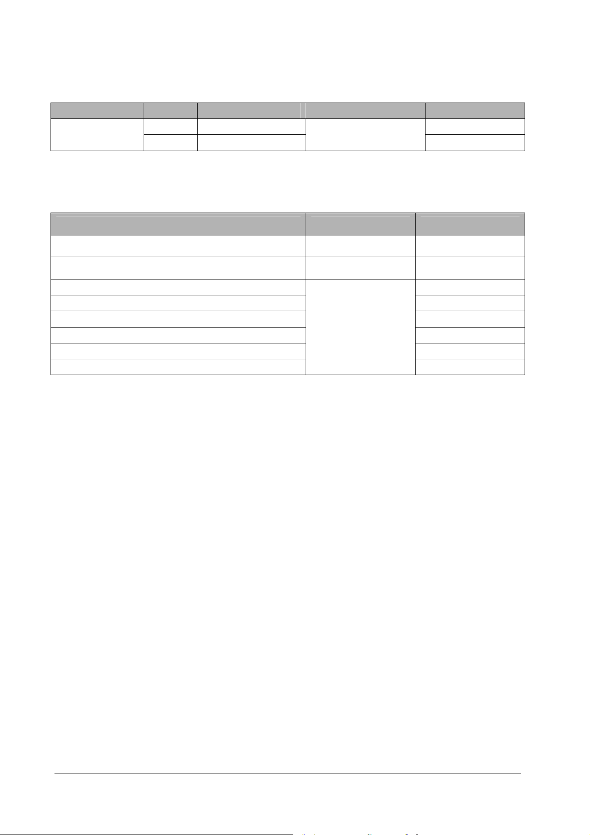
14.2 Therapy Accessories
Description Model Applicable patient Remark PN
Multifunction
electrode pads
MR60 Adult
Disposable (5 sets/pack)
MR61 Pediatric 0651-30-77008
0651-30-77007
14.3 Miscellaneous
Description Model PN
Rechargeable lithium ion battery LI24I001A 022-000047-00
Disposable battery LM34S001A 022-000124-00
Charger Station kit (with international power cord)
Charger Station kit (with US power cord) 115-009188-00
Charger Station kit (with Indian power cord) 115-009189-00
BatteryFeed 20
Charger Station kit (with EU power cord) 115-009190-00
Charger Station kit (with Brazilian power cord) 115-009191-00
Charger Station kit (with UK power cord) 115-009192-00
115-009187-00
14-2
Page 75

A Specifications
Items marked with “*” symbol are available for Pro only.
A.1 General Specifications
Type of protection against
electrical shock
Degree of protection against
electric shock
Mode of operation Continuous
Degree of protection against
harmful ingress of solid
Degree of protection against
harmful ingress of water
Degree of mobility Portable
Size
Width × depth × height 288 × 211 × 79.5 mm
Weight
Main Unit 2.3 kg (without battery)
Rechargeable Battery 0.5 kg
Disposable Battery 0.4 kg
Display
Type TFT Color LCD
Size 7 inch
Resolution 800×480 pixels
Viewed waveforms 1
Wave viewing time Max. ≥ 6s (ECG)
Equipment connectors
USB connector Connects USB flash memory
Audio Indicator
Equipment energized from an internal electrical power source (battery).
Type BF defibrillation proof for external defibrillation.
Type CF defibrillation proof for ECG*
IP5X
IPX5
Speaker
Gives alarm tones (45 to 85 dB), key tones, QRS tones;
Supports PITCH TONE and multi-level tone modulation;
Alarm tones comply with IEC60601-1-8.
A-1
Page 76

A.2 Defibrillator Specifications
Defibrillation mode Manual Defib, synchronous cardioversion, AED
Defibrillation waveform
Defibrillation electrodes Multifunction electrode pads
Range of selected energy
External defibrillation 1, 2, 3, 4, 5, 6, 7, 8, 9, 10, 15, 20, 30, 50, 70, 100, 150, 170, 200, 300, 360 J
Patient impedance range
External defibrillation 25 to 200 Ω
360 J defibrillation waveform into impedance of 25Ω, 50Ω, 75Ω, 100Ω, 125Ω, 150Ω, 175Ω
Biphasic truncated exponential (BTE) waveform, auto-compensation according to patient
impedance
Voltage (V)
Time (ms)
A-2
Page 77

Selected energy accuracy
Impedance
Energy
1 J 1 1 1 0.9 0.9 0.9 0.8 ±2J
2 J 2 2 2 1.9 1.8 1.7 1.6 ±2J
3 J 2.9 3 2.9 2.8 2.7 2.6 2.4 ±2J
4 J 3.9 4 3.9 3.7 3.6 3.4 3.2 ±2J
5 J 4.9 5 4.9 4.7 4.5 4.3 4.1 ±2J
6 J 5.8 6 5.8 5.6 5.3 5.1 4.9 ±2J
7 J 6.8 7 6.8 6.6 6.3 6 5.7 ±2J
8 J 7.8 8 7.8 7.4 7.1 6.8 6.5 ±2J
9 J 8.8 9 8.8 8.4 8 7.7 7.3 ±2J
10 J 9.7 10 9.7 9.3 8.9 8.5 8.1 ±2J
15 J 15 15 15 14 13 13 12 ±15%
20 J 20 20 20 19 18 17 16 ±15%
30 J 29 30 29 28 27 25 24 ±15%
50 J 49 50 49 47 45 43 41 ±15%
70 J 68 70 68 65 62 60 57 ±15%
100 J 97 100 97 93 89 85 81 ±15%
150 J 146 150 146 140 134 128 122 ±15%
170 J 166 170 166 159 151 145 138 ±15%
200 J 195 200 195 187 178 170 163 ±15%
300 J 292 300 292 280 267 255 244 ±15%
360 J 351 360 350 336 321 306 293 ±15%
Charge time (Note: at 20 C of ambient temperature)
Rechargeabl
e battery
Disposable
battery
Synchronized discharge delay
Local synchronized discharge delay < 60ms (from the peak of R-wave)
New and fully charged <5 s <8 s <10 s <10 s <20 s <20 s
New and fully charged after
15 times of 360J discharges
New / / <10 s <17 s <20 s <27 s
New after 15 times of 360J
discharges
25Ω 50Ω 75Ω 100Ω 125Ω 150Ω 175Ω Accuracy
Charge time
(Manual Defib)
200J 360J 200J 360J 200J 360J
<6 s <9 s <10 s <10 s <20 s <20 s
/ / <10 s <17 s <20 s <27 s
From initiation of rhythm
analysis to charge done
From initial power
on to charge done
A-3
Page 78

AED
Energy level: 100 to 360J, configurable;
Shock series
Shockable rhythm VF, VT (HR>150bpm and QRS width>120ms)
Shocks: 1, 2, 3, configurable;
Meeting AHA guidelines 2010 by default.
AED ECG Analysis Performance
Rhythm Class Performance requirement Remark
Shockable rhythm
Ventricular fibrillation
Shockable rhythm
Ventricular tachycardia
Non-shockable rhythm
Normal sinus rhythm
Non-shockable rhythm
Asystole
Non-shockable rhythm
All other non-shockable rhythms
Sensitivity > 90% Meets IEC 60601-2-4 and AAMI DF80
requirement and AHA recommendation
Sensitivity > 75% Meets IEC 60601-2-4 and AAMI DF80
requirement and AHA recommendation
Specificity > 99% Meets IEC 60601-2-4 and AAMI DF80
requirement and AHA recommendation
Specificity > 95% Meets IEC 60601-2-4 and AAMI DF80
requirement and AHA recommendation
Specificity > 95% Meets IEC 60601-2-4 and AAMI DF80
requirement and AHA recommendation
A.3 Monitor Specifications
ECG
Patient connection 3-lead ECG cable or multifunction electrode pads
ECG inputs
Gain
Paper speed
Bandwidth
(-3dB, ECG lead set)
Bandwidth (-3dB, defibrillation
electrodes)
Common mode rejection
(ECG lead set)
Common mode rejection
(defibrillation electrodes)
Notch filter
ECG signal range
Defibrillation electrodes: pads
3-lead ECG set: I, II, III
1.25 mm/mV (×0.125), 2.5 mm/mV (×0.25), 5 mm/mV (×0.5), 10 mm/mV (×1), 20
mm/mV (×2), 40mm/mV (×4) and Auto. Error less than 5%
25 mm/s, error no more than 10%
Monitor mode:
Therapy mode:
Therapy mode:
Monitor mode:
Therapy mode:
Therapy mode: >90 dB
50/60Hz,
In Monitor and Therapy mode: notch filter turns on automatically
With a sensitivity of 10 mm/mv, positive and negative signals between 0.2 mV to
0.8 mV can be detected and HR value be displayed.
0.5 Hz~40 Hz (
1 Hz~20 Hz (
1 Hz~20 Hz (
>90 dB
dB 0.4
dB 3.0
dB 0.4
dB 3.0
dB 0.4
dB 3.0
)
)
)
A-4
Page 79

ECG
Electrode offset potential tolerance ±1 V
HR measurement range
HR accuracy ±1% or ±1bpm, which ever is greater
HR resolution 1 bpm
Lead-off detection current
Baseline recovery time <5 s (after defibrillation)
Tall T-wave rejection capability
Pediatric
Adult
Measuring electrode: <0.1 A
Drive electrode: <1 A
When the test is performed based on part 4.1.2.1 c) of ANSI/AAMI EC 13-2002,
the heart rate meter will reject all 100 ms QRS complexes with less than 1.2 mV
of amplitude, and T waves with T-wave interval of 180 ms and those with Q-T
interval of 350 ms.
Meets the requirements of ANSI/AAMI EC13-2002: section 4.1.2.1 e). The heart
rate reading after 20 seconds of stabilization is:
15 to 350 bpm
15 to 300 bpm
Response to irregular rhythm
Response to change in heart rate
Time to alarm for tachycardia
Heart rate averaging
Ventricular bigeminy (3a):
Slow alternating ventricular bigeminy (3b):
Rapid alternating ventricular bigeminy (3c):
Bidirectional systoles (3d):
Meets requirements of ANSI/AAMI EC13-2002: section 4.1.2.1 f).
From 80 to 120 bpm: less than 11 s;
From 80 to 40 bpm: less than 11 s;
Meets the requirements of ANSI/AAMI EC13-2002: section 4.1.2.1 g).
Waveform
4ah - range:
4a - range:
4ad - range:
4bh - range:
4b - range:
4bd - range:
In compliance with the requirements in Clause 4.1.2.1 d)of ANSI/AAMI
EC13-2002, the following method is used:
If the last 3 consecutive RR intervals are greater than 1200 ms, the 4 most recent
RR intervals are averaged to compute the HR. Otherwise, heart rate is computed
by subtracting the maximum and minimum ones from the most recent 12 RR
intervals and then averaging them.
The HR value displayed on the monitor screen is updated every second.
11 s
11 s
11 s
11 s
11 s
11 s
80±1 bpm
60±1 bpm
120±1 bpm
90±2 bpm
Arrhythmia Analysis Classifications
Asystole, Shockable rhythm (V-Fib/V-Tach), Vtac, Vent. Brady, Extreme Tachy,
Extreme Brady, PVCs/min, PVC, Couplet, VT>2, Bigeminy, Trigeminy, R on T,
Tachy, Brady, PNP, PNC, Vent. Rhythm, Multif. PVC, Nonsus. Vtac, Irr. Rhythm
A-5
Page 80

Pace Pulse
Pace pulses meeting the following conditions are labelled with a PACE marker:
Pace pulse markers
Pace pulse rejection
Amplitude:
Width:
Rise time:
Meets the requirements of ANSI/AAMI EC13-2002: section 4.1.4.1 and 4.1.4.3.
The following pulses will be rejected.
Amplitude:
Width:
Rise time:
Minimum input slew rate:
±2 to ±700 mV
0.1 to 2 ms
10 to 100 µs
±2 to ±700 mV
0.1 to 2 ms
10 to 100 µs
10V/s RTI
A.4 Power Supply Specifications
Rechargeable Battery (new and fully charged, at 20 C of ambient temperature)
Battery type
Charge time Less than 2.5 hours to 90% and less than 3 hours to 100% with BatteryFeed 20 charger station
Run time
14.8V/3Ah, smart lithium ion battery, rechargeable and free of maintenance, one battery can be
configured
Work mode Work time Testing condition
Monitoring ≥ 12 hours
≥300 discharges 200J discharges at a frequency of 3 times/min
Defibrillation
≥200 discharges 360J discharges at a frequency of 3 times/min
LCD brightness set to low, wireless function off, not
performing defibrillation charges or discharges, and audio off
Battery fuel gauge 5 LEDs indicating the current battery charge level
Remaining charge
after “Low Battery”
is reported
Disposable Battery (new, at 20 C of ambient temperature)
Battery type Disposable, free of maintenance
Shelf life (before
insertion)
Standby life (after
insertion)
Run time
Battery fuel gauge Battery symbol on the display indicating the current battery level
Remaining charge
after “Low Battery”
is reported
At least 20 minutes of ECG monitoring (under the work condition of low LCD brightness, with wireless
function turned off, not performing defibrillation charges or discharges, and audio off) and at least 10
200J discharges
5 years from date of manufacture when stored and maintained as required
4 years when stored and maintained as required
Work mode Work time Testing condition
Monitoring ≥ 12 hours
≥300 discharges 200J discharges at a frequency of 3 times/min
Defibrillation
≥200 discharges 360J discharges at a frequency of 3 times/min
At least 20 minutes of ECG monitoring (under the work condition of low LCD brightness, with wireless
function turned off, not performing defibrillation charges or discharges, and audio off) and at least 10
200J discharges
LCD brightness set to low, wireless function off, not performing
defibrillation charges or discharges, and audio off
A-6
Page 81

A.5 Alarm Specifications
Alarm levels High, medium, low level alarms, complying with IEC 60601-1-8
Alarm categories Physiological alarms, technical alarms
Parameter alarm setting
Auto alarm limits Parameter alarm limits can be automatically adjusted according to currently measured vital signs
ECG alarm properties can be set in the [ECG Setup] menu
A.6 Data Management Specifications
Data storage Inner flash memory, 512 M Bytes
Waveform storage Up to 8 hours of consecutive ECG waveform or waveform of up to 100 patients
Event recording Up to 1000 events
Voice recording Max. 180 minutes in total
Data export Data can be exported to a PC through a USB flash memory
A.7 Wireless Network
Standard IEEE 802.11 b/g
Operating Frequency band (MHz) 2412 to 2472
Transmitter Out Power (Typical) (dBm)
16 2
A.8 Environmental Specifications
Main unit
Item Temperature (ºC) Relative humidity Barometric
Operating
conditions
Storage
conditions
BatteryFeed 20 charger station
Item Temperature (ºC) Relative humidity Barometric
Operating conditions 0 to 45 ºC 10% to 95%, noncondensation 57.0 to 106.2 kPa
Storage conditions -30 to 70 ºC 10% to 95%, noncondensation 57.0 to 106.2 kPa
0 to 50 (At lease 60 minutes of working time when the
temperature reduces from room temperature to -20ºC)
-30 to 70 ºC
5% to 95%, noncondens
ation
5% to 95%,
noncondenstion
57.0 to 106.2 kPa
57.0 to 106.2 kPa
A-7
Page 82

Shock
Complies with requirements of 21.102, ISO9919:
Peak acceleration: 1000m/s2 (102g)
Duration: 6ms
Pulse shape: half-sine
Number of shocks: 3 shocks per direction per axis (18 total)
Vibration
Complies with requirements of 21.102, ISO9919.
Bump
Complies with the requirements of 6.3.4.2, EN1789.
Peak acceleration: 15g
Duration: 6ms
Number of impacts: 1000
Impact direction: vertical impacts are applied when the equipment under test is placed at normal operating position.
Drop
1.5 m per IEC 68-2-32
A-8
Page 83

B EMC
The equipment meets the requirements of IEC 60601-1-2.
NOTE
Use of accessories, transducers, and cables other than those specified may result in increased emission
and/or decreased electromagnetic immunity of the defibrillator/monitor.
The equipment or its components should not be used adjacent to or stacked with other devices. If adjacent
or stacked use is necessary, the equipment should be observed to verify normal operation in the
configuration in which it will be used.
The equipment needs special precautions regarding EMC and needs to be installed and put into service
according to the EMC information provided below.
Other devices may affect this monitor even though they meet the requirements of CISPR.
When the inputted signal is below the minimum amplitude provided in technical specifications, erroneous
measurements could result.
Portable and mobile RF communications equipment may affect this equipment.
Guidance and Declaration - Electromagnetic Emissions
The equipment is suitable for use in the electromagnetic environment specified below. The customer or the user of the
equipment should assure that it is used in such an environment.
Emission test Compliance Electromagnetic environment - guidance
RF emissions
CISPR 11
RF emissions
CISPR 11
Guidance and Declaration - Electromagnetic Immunity
The equipment is suitable for use in the electromagnetic environment specified below. The customer or the user of the
equipment should assure that it is used in such an environment.
Immunity test IEC 60601 test level Compliance level Electromagnetic environment - guidance
Electrostatic discharge
(ESD)
IEC 61000-4-2
Power frequency
(50/60 Hz) magnetic
field
IEC 61000-4-8
±6 kV contact
±8 kV air
3 A/m 3 A/m Power frequency magnetic fields should be at
Group 1 The equipment uses RF energy only for its internal function.
Therefore, its RF emissions are very low and are not likely to
cause any interference in nearby electronic equipment.
Class B Meet the requirements of Class B
±6 kV contact
±8 kV air
Floors should be wood, concrete or ceramic tile. If
floors are covered with synthetic material, the
relative humidity should be at least 30%.
levels characteristic of a typical location in a
typical commercial or hospital environment.
B-1
Page 84

Guidance and Declaration - Electromagnetic Immunity
The equipment is suitable for use in the electromagnetic environment specified below. The customer or the user of the
equipment should assure that it is used in such an environment.
IEC 60601
Immunity test
Conduced RF
IEC 61000-4-6
Radiated RF
IEC 61000-4-3
Test level Compliance level Electromagnetic environment - guidance
3 Vrms
150k to 80 MHz
Outside ISM
bandsa
10 Vrms
150kHz to 80MHz
in ISM bandsa
(for life support
devices)
10V/m
80 MHz to 2.5 GHz
(for life support
devices)
20V/m
80 MHz to 2.5 GHz
(ISO 9919)
3 Vrms (V1) Portable and mobile RF communications equipment should be
used no closer to any part of the device, including cables, than
the recommended separation distance calculated from the
equation applicable to the frequency of the transmitter.
Recommended separation distance:
3.5
10 Vrms (V2)
10 V/m (E1)
20 V/m (E2)
d
V
1
12
d
V
2
12
d
E
1
23
d
E
1
where P is the maximum output power rating of the transmitter
in watts (W) according to the transmitter manufacturer and d is
the recommended separation distance in meters (m)b.
Field strengths from fixed RF transmitters, as determined by an
electromagnetic site survey, should be less than the compliance
level in each frequency range d
Interference may occur in the vicinity of equipment marked
P
P
80 MHz to 800 MHz
P
800 MHz to 2.5 GHz
P
with the following symbol:
Note 1: At 80 MHz and 800 MHz, the higher frequency range applies.
Note 2: These guidelines may not apply in all situations. Electromagnetic propagation is affected by absorption and reflection
from structures, objects and people.
a The ISM (industrial, scientific, and medical) bands between 150 kHz and 80 MHz are 6.765 MHz to 6.795 MHz; 13.553 MHz to
13.567 MHz; 26.957 MHz to 27.283 MHz; and 40.66 MHz to 40.70 MHz.
b Compliance level in the ISM frequency bands between 150 kHz to 80 MHz and in the frequency range 80 MHz to 2.5 GHz are
intended to decrease the likelihood that portable/ mobile communication equipment could cause interference if it is
inadvertently brought into patient areas. For this reason, an additional factor of 10/3 is used in calculating the recommended
separation distance for transmitters in these frequency ranges.
c Field strengths from fixed transmitters, such as base stations for radio (cellular/cordless) telephones and land mobile radios,
amateur radio, AM and FM radio broadcast and TV broadcast cannot be predicted theoretically with accuracy. To assess the
electromagnetic environment due to fixed RF transmitters, an electromagnetic site survey should be considered. If the
measured field strength in the location in which the device is used exceeds the applicable RF compliance level above, the device
should be observed to verify normal operation. If abnormal performance is observed, additional measures may be necessary,
such as reorienting or relocating the device.
d Over the frequency ranges 150 kHz to 80 MHz beyond ISM band, field strengths should be less than 3V/m; within ISM band,
field strengths should be less than 10V/m.
B-2
.
Page 85

Rated Maximum
Output power of
Transmitter Watts
(W)
0.01 0.12 0.12 0.12 0.23
0.1 0.38 0.38 0.38 0.73
1 1.20 1.20 1.20 2.30
10 3.80 3.80 3.80 7.30
100 12.00 12.00 12.00 23.00
For transmitters at a maximum output power not listed above, the recommended separation distanced in meters (m) can be
determined using the equation applicable to the frequency of the transmitter, where P is the maximum output power rating
of the transmitter in watts (W) according to the transmitter manufacturer.
Note 1: At 80 MHz and 800 MHz, the higher frequency range applies.
Note 2: The ISM (industrial, scientific, and medical) bands between 150 kHz and 80 MHz are 6.765 MHz to 6.795 MHz; 13.553
MHz to 13.567 MHz; 26.957 MHz to 27.283 MHz; and 40.66 MHz to 40.70 MHz.
Note 3: An additional factor of 10/3 is used in calculating the recommended separation distance for transmitters in the ISM
frequency bands between 150 kHz to 80 MHz and in the frequency range 80 MHz to 2.5 GHz to decrease the likelihood that
portable/ mobile communication equipment could cause interference if it is inadvertently brought into patient areas.
Note 4: These guidelines may not apply in all situations. Electromagnetic propagation is affected by absorption and reflection
from structures, objects and people.
Separation Distance According to Frequency of Transmitter (m)
150 kHz to 80 MHz
outside ISM bands
3.5
d
P
V
1
150 kHz to 80 MHz in
ISM bands
d
12
P
V
2
80 MHz to 800 MHz
d
12
E
P
1
800 MHz to 2.5 GHz
23
d
E
1
P
B-3
Page 86

FOR YOUR NOTES
B-4
Page 87

C BeneHeart D1 User Checklist
Inspect the equipment as recommended. Place a “√” in the “Pass/Fail” box as you check the item , or place a “-” if not
applicable. Describe the problem if there is any abnormity.
Equipment Name: Serial Number: Department:
Item Requirements Pass/Fail Description of Abnormity
Equipment/Accessory
appearance
Battery Battery installed and available
Pads Pre-connected to the equipment, with
Service indicator Lit and green
Checked by: Date:
Clean, no foreign substance, no crack
intact package, and within validity
C-1
Page 88

FOR YOUR NOTES
C-2
Page 89

D Prompt Messages
This chapter lists the prompt audio and text messages that might appear on your equipment.
Source Message Audio
System
Battery Depleted! Replace Battery Now. Battery Depleted! Replace Battery Now.
AED
CPR
/ Adult mode.
/ Pediatric mode.
Remove Clothing Remove clothing from patient’s chest.
Take Out Pads Package Take out pads package from back of
AED.
Plug in Pads Connector Plug in Pads Connector
Remove Pads Tear open package and remove pads
Peel Pads Peel pads from plastic liner.
Apply Pads Apply pads to patient’s bare chest as
shown.
Analyzing, Do Not Touch Patient! Analyzing now. Do not touch the
patient!
Artifact Detected, Cannot Analyze Artifact Detected.
Motion Detected, Cannot Analyze Motion Detected,
Shock Advised! Charging to %sJ Shock Advised! Charging
Charge Failed! Charge Failed!
Do Not Touch Patient! Press Shock Button Do Not Touch the Patient! Press the
Shock Button
Shock Delivered Shock Delivered
Impedance Too Low, Charge Removed Impedance Too Low, Charge Removed
Impedance Too High, Charge Removed Impedance too high. Charge removed.
Abnormal Energy Delivery Abnormal Energy Delivery
No Shock Advised! No Shock Advised! It is safe to touch the
patient.
No Shock Advised! Monitoring No Shock Advised! Attend to patient.
Charge Removed Charge Removed
Shock Button Not Pressed, Charge Removed Shock Button Not Pressed, Charge
Removed
Disarming Failed Disarming Failed
Start CPR Start CPR
Interlock the Fingers
Place Hands on Patient's Chest
Place One Hand on Patient's Chest Place One Hand on Patient's Chest
Keep Arms Straight Keep Arms Straight
Interlock the Fingers
Place Hands on Patient's Chest
D-1
Page 90

Source Message Audio
Follow the Metronome to Compress Follow the Metronome to Compress
Give 2 Breaths Give two Breaths
Breathe Breathe
Continue Continue
Stop CPR
Stop Now
Stop CPR
Stop Now
Manual
Defibrillation
Maintenance
User test
/ Adult mode.
/ Pediatric mode.
Plug in Pads Connector /
Apply Pads /
Charging to %s J /
Energy Changed. Please Recharge. /
Charge Failed. Please Recharge. /
Do Not Touch Patient! Press Shock Button /
Shock Delivered /
Impedance Too Low, Charge Removed /
Impedance Too High, Charge Removed /
Abnormal Energy Delivery /
Are you sure to enter [Manual Defib]? /
Are you sure to enter [SYNC]? /
No R-Wave /
Charge Removed /
Shock Button Not Pressed, Charge Removed /
Disarming Failed /
Normal /
Error. Please Perform User Test to Confirm. /
Rechargeable. Normal. /
Rechargeable. Aged. Replace Battery Advised. /
Rechargeable. Error. Replace Battery Advised.
/
Rechargeable. Low Battery. Replace Battery Advised. /
Disposable. Normal. /
Disposable. Error. Replace Battery Advised. /
Disposable. Low Battery. Replace Battery Advised. /
None /
Adult Pads. Normal. Expires X/X. /
Adult Pads. Abnormal. Replace Pads Now. /
Adult Pads,Pads Expires, Replace Pads Advised. /
Adult Pads,X/X Pads Expires, Replace Pads Advised. /
Pediatric Pads,Pads Expires, Replace Pads Advised. /
Pediatric Pads. Normal. Expires X/X. /
Pediatric Pads. Abnormal. Replace Pads Now. /
Pediatric Pads,X/X Pads Expires,Replace Pads Advised. /
Selftest report trans. failed. /
D-2
Page 91

Source Message Audio
Test Passed. /
AED is Ready for Use. /
Tes t Fa iled. /
Call for Service. Service Code: /
Pads Missing. /
Unknown Pads /
Pads Abnormal, Replace Pads Advised /
Pads Expires, Replace Pads Advised /
Replace Battery Advised. Service Code: /
Please Perform User Test to Confirm. /
Replace Battery Advised. /
Configuration
mode
System
upgrade
Archive
Please enter password /
Password incorrect. Try again! /
Normal network. /
Connection failed. Check the network and setup. /
Cannot Reach the Site. Check the site and setup. /
Are you sure to restore to factory default? /
All settings restored to factory default /
Config. file not found. /
Are you sure to import the file and override the current
config.?
Config. updated successfully. /
USB memory not found! /
USB Memory Error. Data Export Failed! /
Config. file exported successfully. /
Searching upgrade file. /
Server is busy. Please retry later. /
Upgrade file is not available. Upgrade cancelled. /
USB memory not found! /
USB Memory Limited Space /
Exporting Data. Please Wait... /
Data Export Completed! /
USB Memory Error. Data Export Failed! /
/
D-3
Page 92

FOR YOUR NOTES
D-4
Page 93

E Electrical Safety Inspection
The following electrical safety tests are recommended as part of a comprehensive preventive maintenance program.
They are a proven means of detecting abnormalities that, if undetected, could prove dangerous to either the patient or
the operator. Additional tests may be required according to local regulations.
All tests can be performed by using commercially available safety analyzer test equipment. These procedures assume
the use of a 601PROXL International Safety Analyzer or equivalent safety analyzer. Other popular testers complying with
IEC 60601-1 used in Europe, such as Fluke, Metron or Gerb, may require modifications to the procedure. Please follow the
instructions of the analyzer manufacturer.
The electrical safety inspection should be periodically performed per year. The safety analyzer also proves to be an
excellent troubleshooting tool to detect abnormalities of line voltage and grounding, as well as total current loads.
E.1 Power Cord Plug
Test Item Acceptance Criteria
The power plug pins No broken or bent pin. No discolored pins.
The power plug
The power cord
The plug body No physical damage to the plug body.
The strain relief No physical damage to the strain relief. No plug warmth for device in use.
The power plug No loose connections.
No physical damage to the cord. No deterioration to the cord.
For devices with detachable power cords, inspect the connection at the device.
For devices with non-detachable power cords, inspect the strain relief at the
device.
E.2 Device Enclosure and Accessories
E.2.1 Visual Inspection
Test Item Acceptance Criteria
No physical damage to the enclosure and accessories.
The enclosure and accessories
E.2.2 Contextual Inspection
Test Item Acceptance Criteria
The enclosure and accessories
No physical damage to meters, switches, connectors, etc.
No residue of fluid spillage (e.g., water, coffee, chemicals, etc.).
No loose or missing parts (e.g., knobs, dials, terminals, etc.).
No unusual noises (e.g., a rattle inside the case).
No unusual smells (e.g., burning or smoky smells, particularly from ventilation holes).
No taped notes that may suggest device deficiencies or operator concerns.
E-1
Page 94

E.3 Device Labelling
Check the labels provided by the manufacturer or the healthcare facilities are present and legible.
Main unit label
Integrated warning labels
E.4 Patient Leakage Current
Patient leakage currents are measured between a selected applied part and mains earth. All measurements have a true
RMS only
The following outlet conditions apply when performing the Patient Leakage Current test.
normal polarity (Normal Condition)
reverse polarity (Normal Condition)
normal polarity with open neutral (Single Fault Condition)
reverse polarity with open neutral (Single Fault Condition)
normal polarity with open earth (Single Fault Condition)
reverse polarity with open earth (Single Fault Condition)
LIMITS
For CF applied parts
10A in Normal Condition
50A in Single Fault Condition
For BF
100A in Normal Condition
500A in Single Fault Condition
applied parts
E.5 Mains on Applied Part Leakage
The Mains on Applied Part test applies a test voltage, which is 110% of the mains voltage, through a limiting resistance,
to selected applied part terminals. Current measurements are then taken between the selected applied part and earth.
Measurements are taken with the test voltage (110% of mains) to applied parts in the normal and reverse polarity
conditions
The following outlet conditions apply when performing the Mains on Applied Part test.
Normal Polarity
Reversed Polarity
E-2
Page 95

LIMITS
For CF applied parts: 50 A
For BF
applied parts: 5000 A
E.6 Patient Auxiliary Current
Patient Auxiliary currents are measured between any selected Applied Part connector and the remaining Applied Part
connector s. All measurements may have a true RMS only response.
The following outlet conditions apply when performing the Patient Auxiliary Current test.
normal polarity (Normal Condition)
reverse polarity (Normal Condition)
normal polarity with open neutral (Single Fault Condition)
reverse polarity with open neutral (Single Fault Condition)
normal polarity with open earth (Single Fault Condition)
reverse polarity with open earth (Single Fault Condition)
LIMITS
For CF
applied parts,
10A in Normal Condition
50A in Single Fault Condition
For BF
100A in Normal Condition
500A in Single Fault Condition
applied parts,
NOTE
Make sure the safety analyzer is authorized comply with requirement of IEC61010-1.
Follow the instructions of the analyzer manufacturer.
E-3
Page 96

FOR YOUR NOTES
E-4
Page 97

F Symbols and Abbreviations
F.1 Units
µA microampere
µV microvolt
A ampere
Ah ampere hour
bpm beat per minute
bps bit per second
ºC centigrade
cm centimeter
dB decibel
ºF fahrenheit
h hour
Hz hertz
in inch
J Joule
kg kilogram
kPa kilopascal
L litre
m meter
min minute
mm millimeter
ms millisecond
mV millivolt
mW milliwatt
rpm breaths per minute
s second
V volt
Ω ohm
F-1
Page 98

F.2 Symbols
–
% percent
/ per; divide; or
+
= equal to
< less than
> greater than
≤ less than or equal to
≥ greater than or equal to
±
× multiply
© copyright
negative, minus
plus
plus or minus
F.3 Abbreviations and Acronyms
AAMI Association for Advancement of Medical Instrumentation
Adu adult
AED Semi-automated external defibrillation
AHA American Heart Association
ANSI American National Standard Institute
aVF left foot augmented lead
aVL left arm augmented lead
aVR right arm augmented lead
CE Conformité Européenne
CISPR International Special Committee on Radio Interference
CPR Cardiopulmonary resuscitation
DC direct current
Defib defibrillation
ECG electrocardiograph
EMC electromagnetic compatibility
EMI electromagnetic interference
ESU electrosurgical unit
FDA Food and Drug Administration
HR heart rate
ID identification
IEC International Electrotechnical Commission
IP internet protocol
Iso isoflurane
LA left arm
LCD liquid crystal display
F-2
Page 99

LED light emitting diode
LL left leg
MRI magnetic resonance imaging
Neo neonate
O2 oxygen
Ped pediatric
PNC pacer not captured
PNP pacer not paced
PVC premature ventricular complex
RA right arm
Rec record, recording
RL right leg
Sync synchronization
USB universal serial bus
F-3
Page 100

FOR YOUR NOTES
F-4
 Loading...