

Page 1

BC-3000 Plus
Auto
Hematology
Analyzer
Service Manual
Page 2

Page 3

Copyright
®
SHENZHEN MINDRAY
Statement
SHENZHEN MINDRAY
Mindray) owns all rights to this unpublished work and intends to maintain this work as
confidential. Mindray may also seek to maintain this work as an unpublished copyright.
This publication is to be used solely for the purposes of reference, operation, maintenance,
or repair of Mindray equipment. No part of this can be disseminated for other purposes.
BIO-MEDICAL ELECTRONICS CO., LTD. 2003
®
BIO-MEDICAL ELECTRONICS CO., LTD. (hereinafter called
In the event of inadvertent or deliberate publication, Mindray intends to enforce its rights to
this work under copyright laws as a published work. Those having access to this work may
not copy, use, or disclose the information in this work unless expressly authorized by
Mindray to do so.
All information contained in this publication is believed to be correct. Mindray shall not be
liable for errors contained herein nor for incidental or consequential damages in
connection with the furnishing, performance, or use of this material. This publication may
refer to information and protected by copyrights or patents and does not convey any
license under the patent rights of Mindray, nor the rights of others. Mindray does not
assume any liability arising out of any infringements of patents or other rights of third
parties.
Content of this manual is subject to changes without prior notice.
PROPERTY OF
®
SHENZHEN MINDRAY
BIO-MEDICAL ELECTRONICS CO., LTD.
ALL RIGHTS RESERVED
Responsibility on the manufacturer party
Mindray is responsible for safety, reliability and performance of this equipment only in the
condition that:
Auto Hematology Analyzer Service Manual (V1.1) i
Page 4

•
all installation, expansion, change, modification and repair of this equipment are
conducted by Mindray qualified personnel;
•
applied electrical appliance is in compliance with relevant National Standards;
•
the instrument is operated under strict observance of this manual.
Note
This equipment is not intended for family usage.
This equipment must be operated by skilled/trained clinical personnel.
Warning
It is important for the hospital or organization that employs this equipment to carry out a
reasonable maintenance schedule. Neglect of this may result in machine breakdown or
injury of human health.
Upon request, Mindray may provide, with compensation, necessary circuit diagrams,
calibration illustration list and other information to help qualified technician to maintain and
repair some parts, which Mindray may define as user serviceable.
ii Auto Hematology Analyzer Service Manual (V1.1)
Page 5

Warranty
Workmanship & Materials
Mindray guarantees new equipment other than accessories to be free from defects in
workmanship and materials for a period of one year from date of shipment under normal
use and service. Mindray's obligation under this warranty is limited to repairing, at
Mindray’s option, any part which upon Mindray's examination proves defective.
THIS WARRANTY IS EXCLUSIVE AND IS IN LIEU OF ALL OTHER WARRANTIES,
EXPRESSED OR IMPLIED, INCLUDING WARRANTIES OF MERCHANT ABILITY OR
FITNESS FOR ANY PARTICULAR PURPOSE.
Exemptions
Mindray's obligation or liability under this warranty does not include any transportation or
other charges or liability for direct, indirect or consequential damages or delay resulting
from the improper use or application of the product or the substitution upon it of parts or
accessories not approved by Mindray or repaired by anyone other than a Mindray
authorized representative.
This warranty shall not extend to any instrument which has been subjected to misuse,
negligence or accident; any instrument from which Mindray's original serial number tag or
product identification markings have been altered or removed, or any product of any other
manufacturer.
Safety, Reliability and Performance
Mindray is not responsible for the effects on safety, reliability and performance of the
BC-3000plus Hematology Analyzer if:
■ assembly operations, extensions, re-adjusts, modifications or repairs are carried out
by persons other than those authorized by Mindray.
■ Personnel unauthorized by Mindray repairs or modifies the instrument.
Auto Hematology Analyzer Service Manual (V1.1) iii
Page 6

Return Policy
Return Procedure
In the event that it becomes necessary to return a unit to Mindray, the following procedure
should be followed:
1. Obtain return authorization. Contact the Mindray Service Department and obtain a
Customer Service Authorization (Mindray) number . The Mindray number must appear
on the outside of the shipping container. Return shipments will not be accepted if the
Mindray number is not clearly visible. Please provide the model number, serial
number, and a brief description of the reason for return.
2. Freight policy. The customer is responsible for freight charges when equipment is
shipped to Mindray for service (this includes customs charges).
Company Contact
Address: Mindray Building, Keji 12th Road South, Hi-tech
Industrial Park, Nanshan, Shenzhen, P. R. China
Phone: +86 755 26582888
Fax: +86 755 26582680
Authorized Representative
Name: Shanghai International Holding Corp. GmbH (Europe)
Address: Eiffestrasse 80 D-20537 Hamburg Germany
Phone: +49 40 2513175
Fax: +49 40 255726
iv Auto Hematology Analyzer Service Manual (V1.1)
Page 7
Conventions Used in This Manual and Instrument
Warnings, Cautions and Notes
Warnings, cautions and notes are used in this manual to alert or signal the reader to
specific information.
WARNING
Warning alerts the user to the possible injury or death associated with the use or
misuse of the instrument.
CAUTION
Caution alerts the user to possible injury or problems with the instrument
associated with its use or problem such as instrument malfunction, instrument
failure, damage to the instrument.
NOTE
Note provides specific information, in the form of recommendations,
pre-requirements, alternative goods or supplemental information.
WARNING
Potential biohazard
Avoid contacting with the sample probe.
WARNING
Auto Hematology Analyzer Service Manual (V1.1) i
Page 8

Page 9

Content
Content
Chapter 1 General………………………………………………...……………………………1-1
1.1 Introduction ..............................................................................................................1-1
1.2 Service Policy...........................................................................................................1-2
1.3 Specification.............................................................................................................1-3
1.4 Panel Description.....................................................................................................1-7
1.4.1 Front Panel and Keys............................................................................................1-7
1.4.2 Rear Panel............................................................................................................1-9
1.4.3 Front review without front panel.......................................................................... 1-11
1.4.4 Right-side view without the door .........................................................................1-12
1.4.5 Left-side view without the door............................................................................ 1-13
1.5 Menu Structure Chart.............................................................................................1-14
Chapter 2 Troubleshooting…………………………………………………………………….2-1
2.1 Check Procedure .....................................................................................................2-1
2.2 Check Items before Instrument Check.....................................................................2-2
2.3 How to Check Sample Data.....................................................................................2-4
2.4 Troubleshooting Erroneous Data............................................................................2-16
2.5 Troubleshooting......................................................................................................2-21
2.6 Alarm......................................................................................................................2-27
Chapter 3 Hardware……………………………………………………………………………3-1
3.1 CPU Board...............................................................................................................3-2
3.2 Analog Signal Board.................................................................................................3-6
3.3 Power Drive Board.................................................................................................3-10
3.4 Keypad...................................................................................................................3-13
3.5 Recorder Board...................................................................................................... 3-14
3.6 Volumetric Metering Board.....................................................................................3-16
3.7 Power Supply Board ..............................................................................................3-18
Chapter 4 Hydraulic System…………………………………………………………………..4-1
4.1 Hydraulic System Block Diagram.............................................................................4-1
4.2 Units of Hydraulic System........................................................................................4-2
4.3 Whole Blood Count Cycle........................................................................................ 4-3
4.4 Flow Charts of Main Procedures..............................................................................4-4
4.4.1 Power on...............................................................................................................4-4
4.4.2 Whole Blood Count ...............................................................................................4-5
4.4.3 Prediluted Count ................................................................................................... 4-6
4.4.4 Startup...................................................................................................................4-7
4.4.5 Flush Apertures.....................................................................................................4-8
4.4.6 Dispense Diluent...................................................................................................4-9
4.4.7 Shut Down ..........................................................................................................4-10
Auto Hematology Analyzer Service Manual (V1.1) 1
Page 10

Content
4.5 Hydraulic System Flow Diagram............................................................................ 4-11
4.5.1 Inspire Sample and Diluent (Whole Blood Mode)................................................ 4-11
4.5.2 Inspire Sample and Diluent (Prediluted Mode) .................................................... 4-12
4.5.3 WBC Injection & Lyse Preparation......................................................................4-13
4.5.4 RBC & Lyse Injection..........................................................................................4-14
4.5.5 Mixture ................................................................................................................4-15
4.5.6 Count Cycle.........................................................................................................4-16
4.5.7 Cleaning..............................................................................................................4-17
4.5.8 Flush...................................................................................................................4-18
4.5.9 Empty Tube.........................................................................................................4-19
Chapter 5 System Structure…………………………………………………………………..5-1
5.1 Disassemble/Replace Parts and Components.........................................................5-1
5.1.1 Disassemble Syringe and Replace Piston ............................................................5-1
5.1.2 Replace Sample Probe .........................................................................................5-7
5.1.3 Replace Sample Probe Wipe Block ....................................................................5-12
5.1.4 Replace Vacuum Chamber.................................................................................5-18
5.1.5 Replace Pump.....................................................................................................5-19
5.1.6 Replace Count Bath............................................................................................5-22
5.1.7 Clean or Replace V11 or V12 Valve....................................................................5-26
5.1.8 Replace V11 or V12 ............................................................................................5-27
5.1.9 Clean V11 or V12................................................................................................5-31
5.1.10 Replace TFT Screen.........................................................................................5-33
5.1.11 Replace Recorder Paper...................................................................................5-35
5.1.12 Replace Recorder Module ................................................................................ 5-37
5.2 Disassemble/assemble Circuit Boards...................................................................5-38
5.3 Connect Power Supply...........................................................................................5-39
5.4 Connect Circuit Boards..........................................................................................5-41
5.4.1 CPU board connectors defined...........................................................................5-43
5.4.2 Power Driver Board Connectors Defined ............................................................ 5-48
5.4.3 Analog Board’s connectors defined.....................................................................5-52
5.4.4 Keyboard Connectors defined.............................................................................5-54
5.4.5 Indicator Board Connector Defined.....................................................................5-55
5.4.6 MTB Connector Defined......................................................................................5-55
Chapter 6 Adjustment………………………………………………………………………….6-1
6.1 General....................................................................................................................6-1
6.2 Adjusted procedures ................................................................................................6-1
6.3 Gain of WBC (whole blood and prediluted) Channel................................................6-4
6.4 Gain of RBC Channel............................................................................................... 6-6
6.5 Gain of PLT Channel.............................................................................................. 6-10
6.6 Gain of HGB Channel ............................................................................................ 6-11
6.7 Adjust Display Brightness.......................................................................................6-12
6.8 Adjust Vacuum and Pressure.................................................................................6-13
2 Auto Hematology Analyzer Service Manual (V1.1)
Page 11

Content
6.9 Adjust Count time...................................................................................................6-14
6.10 Adjust Auto Clean Time........................................................................................6-16
6.1 1 Adjust Volumetric Metering Board ........................................................................6-17
6.12 Re-calibrating Instrument.....................................................................................6-19
Chapter 7 Maintenance………………………………………………………………………..7-1
7.1 Daily maintenance....................................................................................................7-1
7.2 Monthly maintenance...............................................................................................7-1
7.3Half-year maintenance..............................................................................................7-2
Chapter 8 Spare Part List…………..………………………………………………………….8-1
Chapter 9 Performance Test…………………………………………………………………..9-1
Chapter 10 Histograms and Pulse Graphs…………………………………………………10-1
10.1 Histograms...........................................................................................................10-1
10.2 Pulse Graphs .......................................................................................................10-4
10.2.1 Normal Pulse Graphs........................................................................................ 10-4
10.2.2 Abnormal Pulse Graphs .................................................................................... 10-6
Chapter 11 Password and Upgrade software………………………………………………11-1
11.1 Password.............................................................................................................. 11-1
11.2 Upgrade System Software.................................................................................... 11-2
Appendix………………………………………………………………………………………..A-1
Hardware Diagram of BC-3000PLUS.............................................................................A-1
Hydraulic Diagram of BC-3000PLUS .............................................................................A-2
Auto Hematology Analyzer Service Manual (V1.1) 3
Page 12

Page 13

General
Chapter 1 General
1.1 Introduction
CAUTION
To maintain the instrument in normal condition, the user must perform the periodic
maintenance. Refer to the user manual.
This service manual provides useful information to help service personnel to understand,
troubleshoot, service, maintain and repair the Hematology Analyzer.
All replaceable parts or units of this instrument and its optional units are clearly list with
exploded illustration to help you locate the parts quickly.
The maintenance must be periodically performed because the instrument has fluid paths
and precision parts. Accordingly, the user is responsible for performing the periodic
maintenance. The “maintenance” chapter in this service manual describes the
maintenance that should be performed by the qualified service personnel. The
“maintenance” chapter in the user manual describes the maintenance that can be
performed by the user.
NOTE
If the instrument has a problem and there has been no periodic maintenance, the
instrument will usually be normal again by cleaning the fluid paths or replacing a
consumable with a new one.
The information in the user manual is primarily for the user. However, it is important for
service personnel to thoroughly read the user manual and service manual before starting
to troubleshoot, service, maintain or repair this instrument. This is because service
personnel needs to understand the operation of the instrument in order to effectively use
the instrument in order to effectively use the information in the service manual.
Auto Hematology Analyzer Service Manual (V1.1) 1-1
Page 14

General
1.2 Service Policy
CAUTION
Be careful not to directly touch any place where blood is or may spread to.
Wear rubber gloves to protect yourself from infection before doing maintenance.
Our company’s basic policy for technical service is to replace faulty units, printed circuit
boards or parts. We do not support component-level repair of boards and units outside the
factory.
NOTE
When ordering parts or accessories from your nearest distributor, please quote the
part number and part name which is listed in the service manual, and the name or
model of the unit in which the required part is located. This will help us to promptly
attend to your needs.
Always use parts and accessories recommended or supplied by our company to
assure maximum performance from your instrument.
1-2 Auto Hematology Analyzer Service Manual (V1.1)
Page 15
1.3 Specification
Hemoglobin Analysis
Wavelength 525nm
Sampling Features
Volumes Required for Each Analysis:
Whole Blood Mode (vein blood) 13uL
Prediluted Mode (capillary blood) 20uL
Aspirated volumes:
500uL of lyse first dilution per cycle for WBC measurement
300uL of second dilution per cycle for RBC and PLT measurement
Dilution Ratios Whole Blood Prediluted
General
WBC/HGB 1: 308 1:407
RBC/PLT 1:44833 1: 44274
Cell Counting Aperture Size:
WBC 100um
RBC 70um
Throughput more than 60 samples/hour
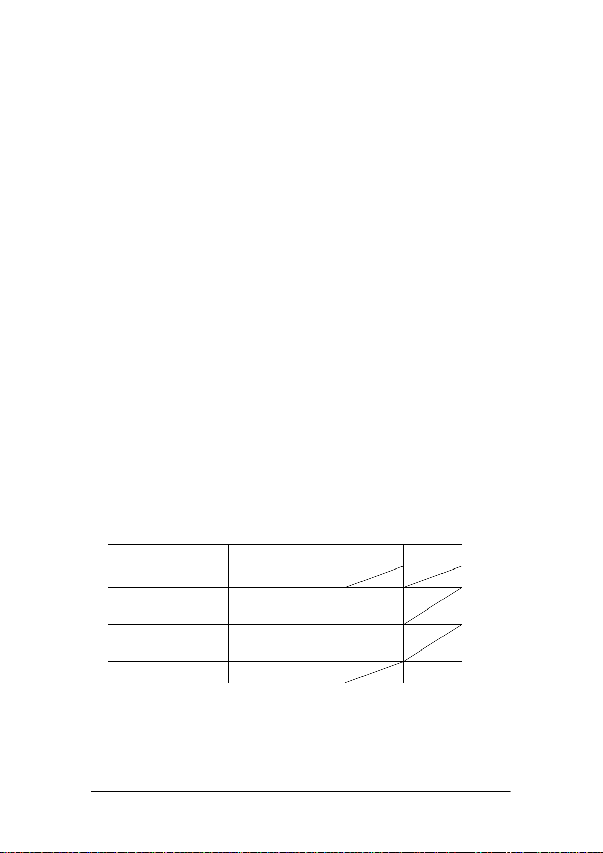
Check Diluent, Rinse and Lyse
The applied volume of each reagent is:
Diluent Rinse Lyse E-Z
Normal Startup 42ml 10ml
Prepare a sample
25.4ml 6ml 0.5ml
(whole blood)
Prepare a sample
25.1ml 6ml 0.26ml
(prediluted)
Normal Shutdown 32ml 10ml 1.6ml
Performance Specifications
Imprecision
Imprecision is based on replicate determinations of the same sample. The first
Auto Hematology Analyzer Service Manual (V1.1) 1-3
Page 16
General
result is not used in the calculation.
Imprecision Specifications
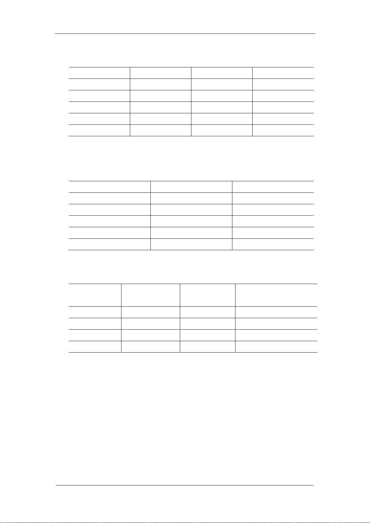
Parameter Level Units CV%
WBC 7.0-15.0 109/L
RBC 3.5-6.0 1012/L
HGB 110 – 180 g/L
MCV 80.0 – 110.0 fL
PLT 200 – 500 109/L
Operating Range
Parameter Range Units
WBC 0.0-999.9 109/L
RBC 0.00-9.99 1012/L
HGB 0-300 g/L
MCV 0-250 fL
PLT 0-3000 109/L
≤ 2.5
≤ 2
≤ 1.5
≤ 0.5
≤ 5
Linearity
Parameter Linearity Range Units
WBC 0.3-99.9 109/L ±0.3 or ±5%
RBC 0.20-9.99 1012/L ±0.05 or ±5%
HGB 0-300 g/L ±2 or ±3%
PLT 10-999 109/L ±10 or ±10%
Display
Liquid Crystal Display(LCD),resolution: 640×480
Input/Output
Two RS232/C serial ports
One printer port
One keyboard interface
Difference
(whichever is greater)
Built-in Thermal Recorder
1-4 Auto Hematology Analyzer Service Manual (V1.1)
Page 17

Printer (optional)
EPSON LX-300, EPSON LX-300+
Scanner(optional)
TYSSO CCD-82
Reagents Required
DILUENT M-30D DILUENT
RINSE M-30R RINSE
LYSE M-30L LYSE
E-Z CLEANSER(Enzyme cleanser) M-30E CLEANSER
PROBE CLEANSER M-30P CLEANSER
Power
Input: AC 220V±10% AC 110V±10%
General
50/60±1 Hz 50/60±1 Hz
Consumption: 180 VA 180 VA
Fuse: 2A 4A
Ambient Temperature and Humidity
Temperature:
15℃~35℃ (59℉~95℉)
Humidity:
10%~85% without condensation
Dimensions
Height Width Depth
46cm 39cm 40cm
Weight
25KG
Recommended Anticoagulant
A salt of K
EDTA with the proper proportion of blood to anticoagulant, as specified by
2
the tube manufacturer.
Sample Identification
An 8-digit identification number is mandatory sample identification.
Auto Hematology Analyzer Service Manual (V1.1) 1-5
Page 18

General
Results Output
The system can transmit sample and control data to an external computer.
Sample results screen shows sample identification number, sample mode, sample
results and any sample result flags.
The system provides a printout of all data.
1-6 Auto Hematology Analyzer Service Manual (V1.1)
Page 19
1.4 Panel Description
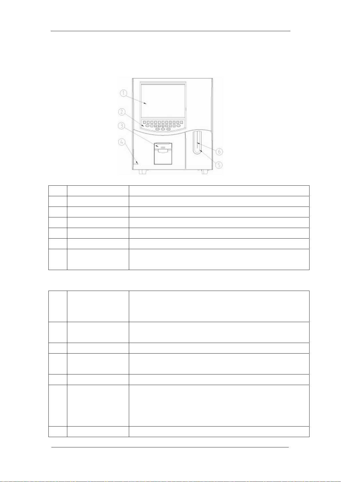
1.4.1 Front Panel and Keys
Figure 1-1
No. Name Description
General
1 Display Screen Display various messages, measured data and histograms
2 Keypad Touch key (all of the description refer to under lists), 23 buttons
3 Recorder Print out measured result
4 Power Light Show hematology analyzer work status
5 [Start] key Press to aspirate the sample and start counting
6 Sample Probe Aspirate the sample
Dispenses the diluent when in capillary blood mode.
Keypad
1
[START]
In Count screen, QC Count screen and Auto Calibration screen,
press it to count. In the status of Adding Diluent, press it to add
Diluent.
2
[MENU]
Press this key to switch between window operation and menu
operation
3
4
[PRINT]
[FEED]
Press this key to print using either recorder or printer
Press this key to feed paper of the recorder. Release it to stop the
operation.
5
6
[MUTE]
[DEL]
Mute the alarm and clear some of the error messages.
Delete the selected data in Review screen. Delete error message
in Error Message screen. Delete reference data and running
control data in QC Edit screen. Call default value in Normal
Range screen.
7
[0]...[9]
Auto Hematology Analyzer Service Manual (V1.1) 1-7
Enter numbers
Page 20

General
8
9
10
11
12
13
14
[↑][↓][←][→]
[ID]
[DILUENT]
[PgUp][PgDn]
[ENTER]
[STARTUP]
[FLUSH]
Move the cursor in the window area or menu area.
Enter the ID number of the sample
In the Count screen of Prediluted mode, press this key to enter
the Adding Diluent status.
Scroll the screen up or down page by page.
Confirm
Clean the tubing, baths and sample probe then check the
background.
Press the key to execute the Flush operation to remove the clogs
1-8 Auto Hematology Analyzer Service Manual (V1.1)
Page 21
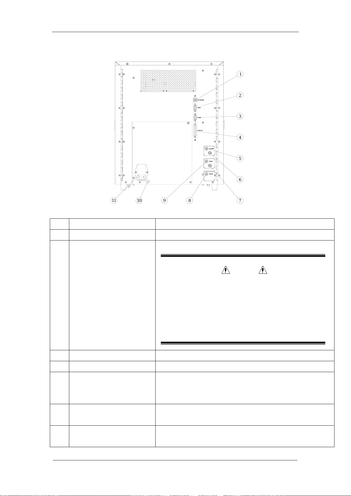
1.4.2 Rear Panel
General
1
2
3
4
5
6
1
1
1
0
9
8
7
Figure 1-2
No. Name Description
1 Keyboard Interface Connect the standard keyboard
2 RS-232C Serial Port 1 Connect computer and transfer data to computer
CAUTION
In order to avoid any safety hazard, only coonect personal
computer which are approved to IEC950
The instrument should only be connected to an external
instrument which complies with the CISPR 11 Second
Edition 1990-09, Group 1 and Class B standard
3 RS-232C Serial Port 2 Connect a bar code scanner
4 Printer Interface Connect the external print er LX-300+ (LX-300)
5 DILUENT Tubing Connector Inlet for diluent. Connect one end of the tube (standard
accessory) to the diluent inlet and attach the other end of the
tube to the diluent
6 BNC socket for DILUENT
sensor
7 BNC socket for RINSE
sensor
Auto Hematology Analyzer Service Manual (V1.1) 1-9
connector for diluent. Connect one end of the connector of the
cable.
connector for rinse. Connect one end of the connector of the
cable.
Page 22
General
8 WASTE Tubing Connector Inlet for waste. Connect one end of the tube (standard
accessory) to the waste inlet and attach the other end of the
tube to the waste
9 RINSE Tubing Connector Inlet for rinse. Connect one end of the tube (standard
accessory) to the rinse inlet and attach the other end of the
tube to the rinse
10 Equipotential ground
terminal
11 Power switch
AC source
Fuse holder
Connects the ground lead to the Equipotential ground terminal
on the wall for earth grounding
Turns power on or off
Connects the AC power cord to supply the AC power to the
instrument
Contains the time lag fuse (T 2A for 220V or T 4A for 110v)
Fuses cut the power off when an abnormality occurs in the
hematology analyzer. Remove the malfunction before
replacing the fuse.
Before replacing a fuse, turn the power off anf disconnect
the AC power cord from the instrument.
Fuse replacement should be done by a qualified person.
CAUTION
1-10 Auto Hematology Analyzer Service Manual (V1.1)
Page 23
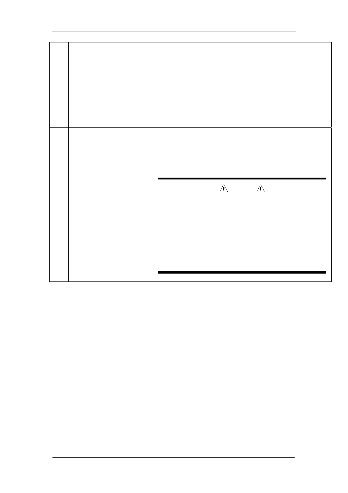
1.4.3 Front review without front panel
General
1
2
3
4
5
9
Figure 1-3
1--- Fluctuating Motor
2--- Sample Probe
3--- Sample Probe Wipe Block
4--- WBC unit shield
5--- RBC/PLT unit shield
6--- [Start] key
7---Valve 11
8--- Valve 12
9---Floppy Disk Driver
6
8
7
Auto Hematology Analyzer Service Manual (V1.1) 1-11
Page 24
General
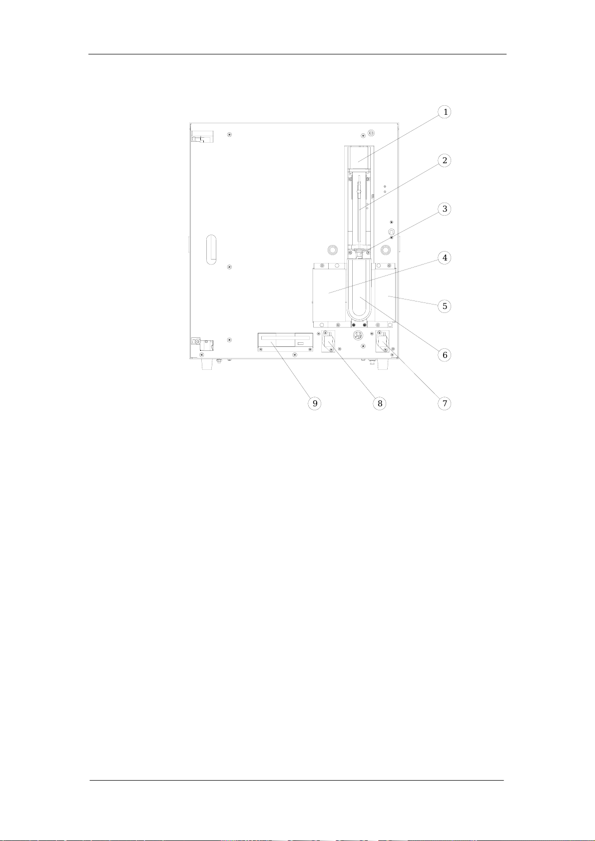
1.4.4 Right-side view without the door
2
2
3
1
2
3
4
2
2
1
2
1
0
9
1
8
1
7
1
6
1
5
1
5
6
7
8
9
1
0
1
1
4
1
3
1
2
Figure 1-4
1--- valve 8 2---volumetric unit
3---vacuum chamber 4---valve 15
5---valve 16 6---valve 14
7---valve 13 8---valve 10
9---valve 2 10--- valve 9
11---2.5ml and 50ul motor 12---10ml motor
13---2.5ml syringe 14---50ul syringe
15---10ml syringe 16---valve 4
17---valve 3 18---valve 1
19---valve 6 20---valve 5
21---valve 17 22---valve 7
23---valve 18
1-12 Auto Hematology Analyzer Service Manual (V1.1)
Page 25
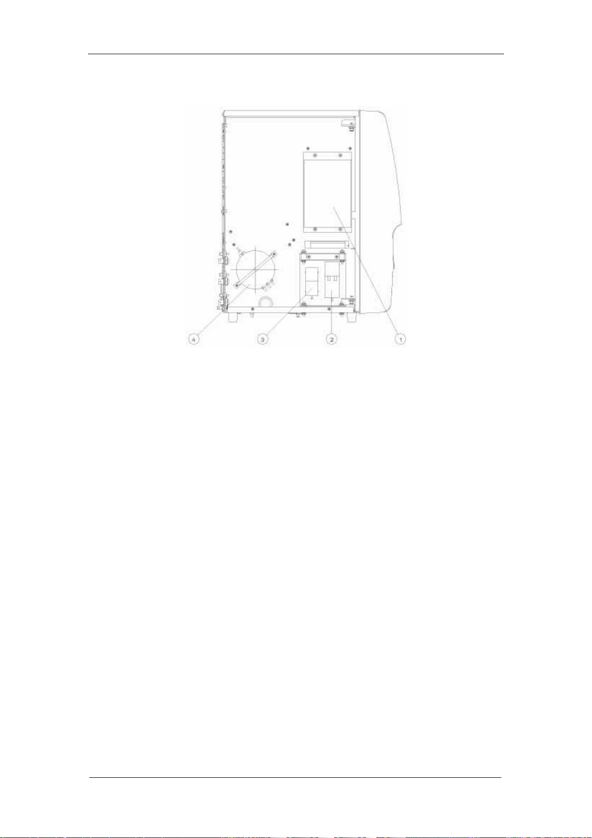
1.4.5 Left-side view without the door
General
Figure 1-5
1---hard disk (Module on disk)
2---vacuum pump
3---pressure pump
4---pressure chamber
Auto Hematology Analyzer Service Manual (V1.1) 1-13
Page 26
General
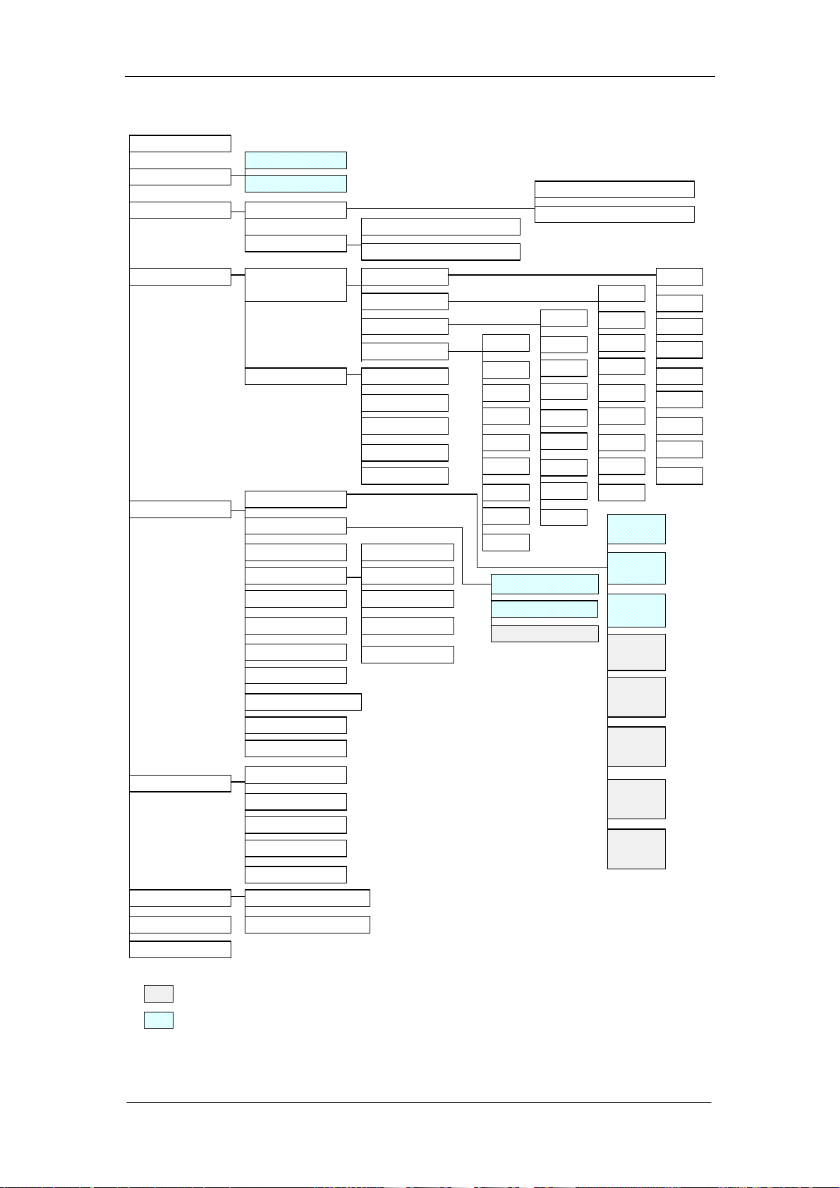
1.5 Menu Structure Chart
Count
Whole Blood
Sample Mode
Review
Prediluted
Sample Review
Search Review
Sample Table R eview
Sample Histogram Review
Search Table Review
Search Histogram Review
Qu a lity Control
Setup
Com merical
Control
X-B Analysis
Print
Count Time
Password
Patie n t L imits
Transm ission
Date & Time
Gain
Auto Clean Time
Re ag e n t E x p. Date
Prin t C a ptio n
Parameter U n its
QC Edit
QC Count
QC Graph
QC Table
Limit
Sample /B atc h
Start/Stop
X-B Graph
X-B Table
General
Man
Woman
Ch ild
Neonate
File 1
File 1
File 2
File 3
File 4
File 5
File 6
File 7
File 8
File 2
File 3
File 4
File 5
File 6
File 7
File 8
File 9
File 9
WBC Count Time
RBC Count Time
Mid Max Width
File 1
File 2
File 3
File 4
File 5
File 6
File 7
File 8
File 9
Prin t
Select
Prin t
Format
Auto
Print
Version
Language
Type
File 1
File 2
File 3
File 4
File 5
File 6
File 7
File 8
File 9
Service
M ain te na n ce
System Status
Valve Test
Prepare to Ship
Error Messa ge
Ca libr atio n
Help
M an u a l C a lib ra ton
Au to C a lib rat ion
Shutdown
:item s ca n be v ie w e d O n ly af ter in pu t th e co rr es po n d in g pa s sword
:included items, not sub-menu
1-14 Auto Hematology Analyzer Service Manual (V1.1)
Pale tte
Recorder
Type
Page 27
Chapter 2 Troubleshooting
r
A
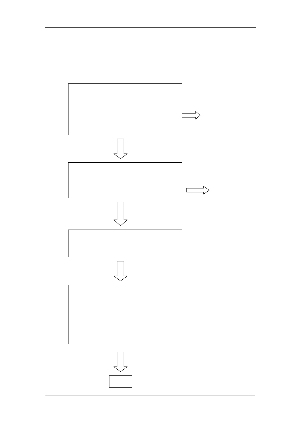
2.1 Check Procedure
Check the instrument according to the check procedure below.
Measurement operation check
Was the quantity of each reagent sufficient fo
measurement?
Were the correct or recommended reagents used?
Was the operating temperature proper?
Was the supplied main power voltage correct?
fter turning on the instrument.
Did the instrument fail to generate an alarm?
NO DILUENT
HARDWARE FAIL
Background noise measurement.
Did the instrument fail to generate an alarm?
Was the result within the specification?
Control measurement
Did the instrument fail to generate an alarm?
Was the result reproducibility good for:
HGB? RBC?
WBC? PLT?
HCT?
(Was the obtained data within the range?)
END
before Instrument Check”
Troubleshooting
Refer to “Check Items
Refer to
“Troubleshooting
and Alarm”
Auto Hematology Analyzer Service Manual (V1.1) 2-1
Page 28

Troubleshooting
2.2 Check Items before Instrument Check
Use the instrument and diluent under the following
Check items before
Instrument check
operating conditions:
Around instrument Diluent
- temperature: 15 to 35℃ temperature: 15 to 30℃
- humidity: 10 to 85%
- atmospheric pressure: 860 to 1060hPa (Working)
If the temperature is less than 15℃, it slows the
reaction rate from hemoglobin to cyanmethemoglobin.
This may result in increase of the hemoglobin data. It
may also result in increase of the WBC count because
the RBCs are not sufficiently hemolysed due to the
lower temperature. Insufficiently hemolyzed RBCs will
be included in the WBC count as RBC ghosts.
Sampled Whole Blood
Handling Check
Storage for Blood Sample
Measure all required parameters soon after sampling
the whole blood from a patient. As time elapses after
blood sampling, the blood cells’ volume and density
change. The ratios of the volume and density
variations depend on the environmental conditions and
patient. If the blood sample isleft in an air conditioned
room for a long time, the volume of the red blood cell
increases and the MCV, RDW and MPV will be
affected, and moreover, the PLT will be easily
aggregated.
WBC part differential
To get high reliability on the acquired data, measure
the blood samples within 6 hours after sampling the
whole blood. If the blood sample is left in an air
conditioned room for a long time, geerally, the WBC
membrane’s resistance against hemolysing reagent is
decreased. Therefore the WBC histogram of the
correct shape cannot be obtained.
Blood Sample from a Patient with Specified Conditions
To measure a blood from a patient who has
hepatopathy, certain special treatments, or is a
neonate, it may be necessary to use a method other
than the hematology. Analyzer. This is because the
RBC membrane’s resistance against hemolysing
2-2 Auto Hematology Analyzer Service Manual (V1.1)
Page 29

Capillary Blood Handing
Check
Troubleshooting
reagent is increased (insufficient hemolysing) and it
will cause an increase of the WBC count when the
blood is measured with the hematology analyzer.
Furthermore, the bilirubin and WBC in the blood may
affect the hemoglobin concentration in the
measurement.
CAUTION
In the capillary blood mode, the instrument
aspirates the diluted sample of 20uL. In this mode,
if the venous blood is incorrectly aspirated instead
of capillary blood, there is a high possibility that
the fluid path is clogged or the background noise
is not easily decreased.
Most causes of data error using capillary blood are due
to incorrect technique for the capillary blood sampling
and diluting. Therefore, take care the following notes
and make a capillary blood sample.
NOTE
Dilute the sampled capillary blood correctly the
first time, because it is difficult to sample the
blood twice from the capillary.
Auto Hematology Analyzer Service Manual (V1.1) 2-3
Page 30

Troubleshooting
2.3 How to Check Sample Data
Background Noise Check
This check is used to make sure that the counted and
calculated data of a diluent sample is not affected by
background noise. If the background checking value
exceeds the tolerable dilute data shown in the table
below, the diluent data counted and calculated before
background noise is reduced erroneous. In the table
below, each diluent data is defined as follows:
Recommended diluent data
This data is best for acquiring accurate data of the
sample.
Acceptable dilunt data
This data is the minimum value for acquiring accurate
data of the sample.
Recommended diluent Data Acceptable diluent Data
WBC 0.0 WBC
RBC 0.00 RBC
HGB 0 HGB 1g/L or 0.1g/dL
HCT 0.0 HCT 0.5%
PLT 3 PLT
Refer to “Troubleshooting Erroneous Data” of this
chapter for the possible causes of background noise
and how to reduce it.
Check Procedure
1. Press the start key to count and calculate the
2. Make sure the counted and calculated data is less
Parameter Data Check with Diluent
Check that the background values are less than or
equal to the data in the previous table. Discard the
other parameter values because they are not affected
by noise.
Especially check the data for the PLT parameters.
When the diluent includes the particles of dust smaller
9/L
10
0.3x
12/L
10
0.03x
9/L
10
10x
diluent. There is no need to aspirate the diluent
from the sampling probe.
than or equal to the acceptable diluent data as
shown upper. If they are out of range, decrease the
background noise.
2-4 Auto Hematology Analyzer Service Manual (V1.1)
Page 31

Troubleshooting
than WBC and RBC parameters, the data of them is
not affected by the dust but the data for the PLT
parameter increases because the volume for the PLT
parameter is smaller than the WBC and RBC
parameters. I f the data for the PLT parameter exceeds
10X10
9
/L, do the action described below to reduce the
background noise.
Reducing Background Noise
To reduce the background noise when the background
check value exceeds the acceptable diluent data
shown in the previous table, perform the following.
1. Make sure connecting grounding well.
2. Execute the “clean Bath” program which in the
service menu. If this does not reduce the
background noise, perform the following steps.
3. Execute the “E-Z cleanser cleaning” and “Diuent
Prime” program.
4. Perform the background check to make sure that
the background noise is reduced.
If the data of the background check is still outside the
acceptable diluent data values shown in the previous
table, replace the diluent with diluent from a new,
sealed container.
NOTE
When the instrument is used every day and the
background noise rarely exceeds the lower limit
for the diluent data, the instrument is not severely
contaminated. However, this contamination builds
up in the instrument and cannot be easily removed
if the instrument is not cleaned periodically.
Auto Hematology Analyzer Service Manual (V1.1) 2-5
Page 32

Troubleshooting
Reproducibility Check This check is used to check reproducibility of the
instrument, using pintout data value of a diluted
sample from the same hematology control. When the
values are out the specification range, the
reproducibility of the instrument is poor. If the
reproducibility is found to be poor, this printed result is
used to troubleshoot the instrument as described in
“Troubleshooting Erroneous Data” of this chapter.
Check Procedure
1. Reduce the background noise. Refer to
“Background Noise Check” of this chapter.
2. Access “Quality Control” → normal level
Controls→ QC Edit→ File “X” to set a new control
file and input each parameter’s specification.
3. Access “Quality Control” → Commercial
Controls→ QC Count→ Count a diluted sample
from the same sufficiently mixed hematology
control 10 times.
4. Access “Quality Control” → Commercial
Controls→ QC Graph→ File “X” to review the
result and CV value.
5. If you want to print out the displayed values with an
built-in thermo-printer unit, press the print key
which on the keypad directly in the graph screen or
table screen.
Data Check with Hematology Control
The CV (Coefficient of Variation) indicates the data
reproducibility on each parameter. A lower CV value
for a parameter indicates better reproducibility for the
parameter (i.e. each sample data for the parameter
deviates less).
Check the CV value for each parameter by comparing
it with the CV specifications (as shown in the next page)
described in the brochure. You get the CV value by
counting a normal concentration hematology control
10 times consecutively.
If the acquired CV values are out of the CV
specifications, the reproducibility of the instrument is
poor. To troubleshoot the instrument, refer to
“Troubleshooting Erroneous Data” of this chapter.
2-6 Auto Hematology Analyzer Service Manual (V1.1)
Page 33
Troubleshooting
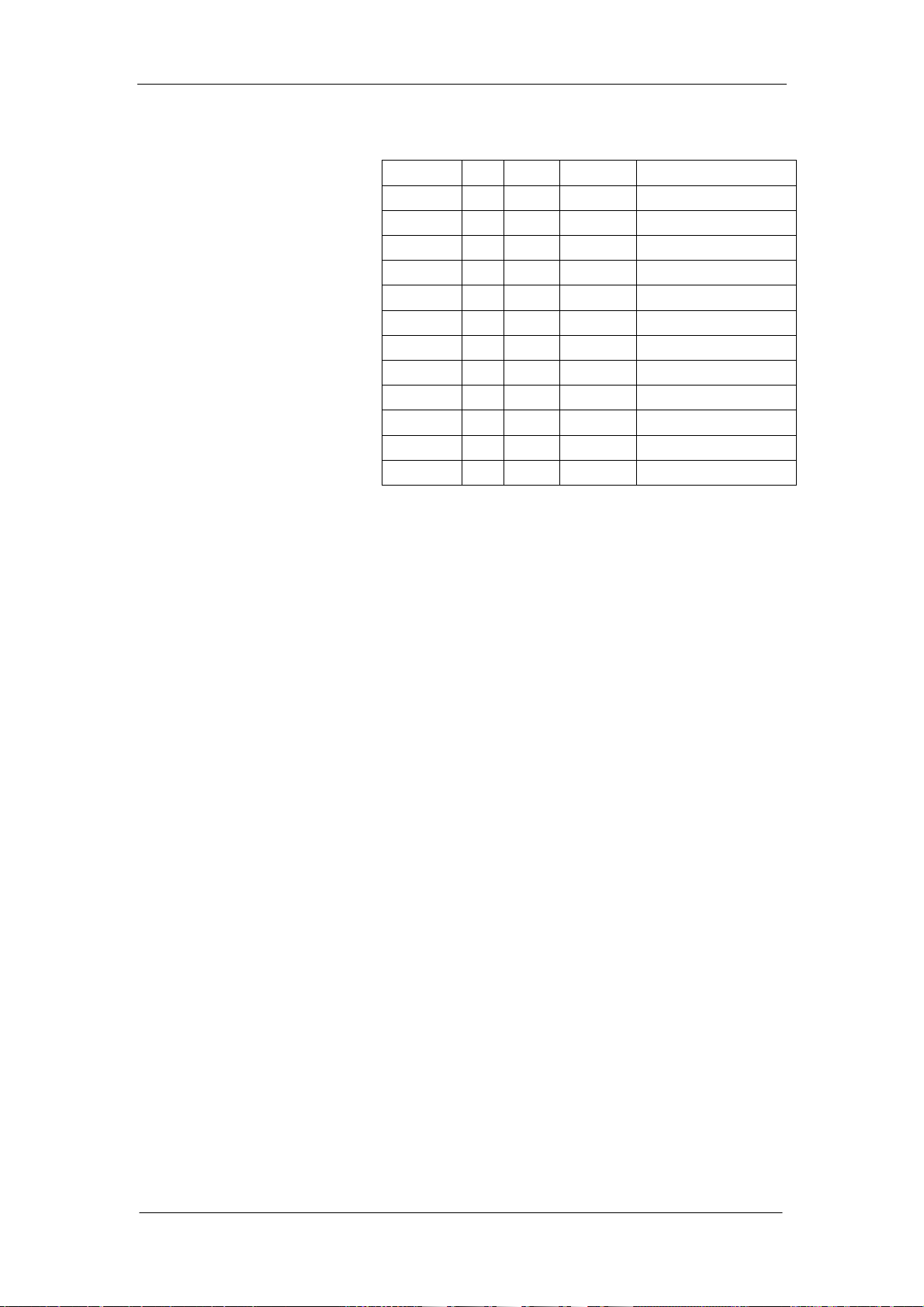
<Data example and CV specifications>
N X CV% CV Specification
WBC 10 10.0 1.05 2.5% or less
RBC 10 4.23 1.22 2% or less
HGB 10 130 0.77 1.5% or less
PLT 10 201 3.25 5% or less
Lymph# 10 4.0 1.47
Lymph% 10 41.0 1.28
Gran# 10 4.9 1.77
Gran% 10 48.2 1.15
HCT 10 36.1 1.28
MCV 10 86.9 0.24 0.5% or less
MCH 10 31.6 1.02
MCHC 10 353 1.08
N: Number of samples for each parameter
X: Mean of sample data for each parameter
CV: Standard deviation divided by mean X
Note
Normally, the hematology analyzer counts approx
4.0X10
4
blood cells for 16 seconds per one RBC
counting. The reproducibility for the hematology
analyzer is statistically determined by the number of
blood cells aspirated through the aperture. The
reproducibility is better as the number of counted blood
cells increases; the reproducibility is worse as the
number of counted blood cells decreases. That is, the
acquired data has more deviation when a blood
sample of lower concentration is counted.
The following explanation and diagram show what the
CV values mean for data of each parameter.
For example, when noting the RBC data on the
printout (see the previous table), the mean of the RBC
data is 4.43 and CV is 0.8%. 0.8% of 4.43 is 0.035.
Therefore the range is 4.395 to 4.465 (4.43±0.035).
This means that six of the ten acquired RBC data are
within the range.
Auto Hematology Analyzer Service Manual (V1.1) 2-7
Page 34

Troubleshooting
Accuracy Check
4.37 4.39 4.40 4.43 4.44 4.45 4.45 4.45 4.46 4.47 4.48
(2 data) (6 data) (2 data)
4.395 4.465
This check is used to check the accuracy of the
measurement by comparing the actually measured
data of the hematology control with expected value on
the assay sheet of the hematology control. If there is a
large difference between them, calibrate the
instrument by resetting the calibration coefficient for
each parameter.
Check Procedure
1. Gently take the hematology control out of the
refrigerator and place it in a normal temperature
environment for a while to raise it to room
temperature. The hematology control must be
within the expiration data.
2. Confirm that the hematology control is not
hemolysed. Normally the hematology control is
separated into blood plasma and blood serum of
the hematology control may be mixed. Also, if the
hematology control is frozen, it is hemolysed.
3. Measure each parameter with the hematology
control.
4. Check that the obtained sample data for each
parameter is within the range between the lower
and upper expected values on the assay sheet.
Run the control again, replace a new control to try
again if the results are out of range. After that, if
the result are still unacceptable, recalibrate the
instrument with the following procedures.
5.
When the condition temperaare range is out of (20
to 26℃), control results maybe out of limits.
2-8 Auto Hematology Analyzer Service Manual (V1.1)
Page 35
Troubleshooting
×
Parameter Data Check with Hematology Control
Check that the obtained sample data for each
parameter is within the range of the assay values on
the assay sheet.
NOTES
If the data for any parameter is out of range,
calibrate the instrument according to “Calibration”
of the operator’s manual.
To calibrate the instrument for more accuracy,
refer to the following “Procedure for Instrument
Fine Calibration” of this chapter.
Procedure for Instrument Fine Calibration
The instrument allows the user to input the factors
manually with the range between 75% and 125%.
The procedures of manual are:
1 . Confirm the sample mode.
2 . Run the calibrator in Count screen for at least five
times. The reproducibility of WBC, RBC, HGB, MCV
and PLT must satisfy following limits.
Parameter CV
WBC
RBC
HGB
MCV
PLT
≤2.5
≤2.0
≤1.5
≤0.5
≤5
3. Calculate the new calibration factors.
4. Enter the new calibration factors.
Calculate the New Calibration Factors
Use the below formula to calculate the new calibration
factors
factornew
=
valuereferencefactorold
valuetestofaverage
Auto Hematology Analyzer Service Manual (V1.1) 2-9
Page 36
Troubleshooting
×
Example:
Reference value of WBC = 8.4
In whole blood mode, three running values of WBC are
8.1, 8.0, 8.1, 8.1 and 8.3. The mean value of WBC is
8.12. Old calibration factor in the whole blood mode is
98.9%.
n
x
∑
i
i
1
Mean
=
12.8
==
n
CV < 2%
4.8%9.98
=
factornew
valuereferencefactorold
valuetestofaverage
=
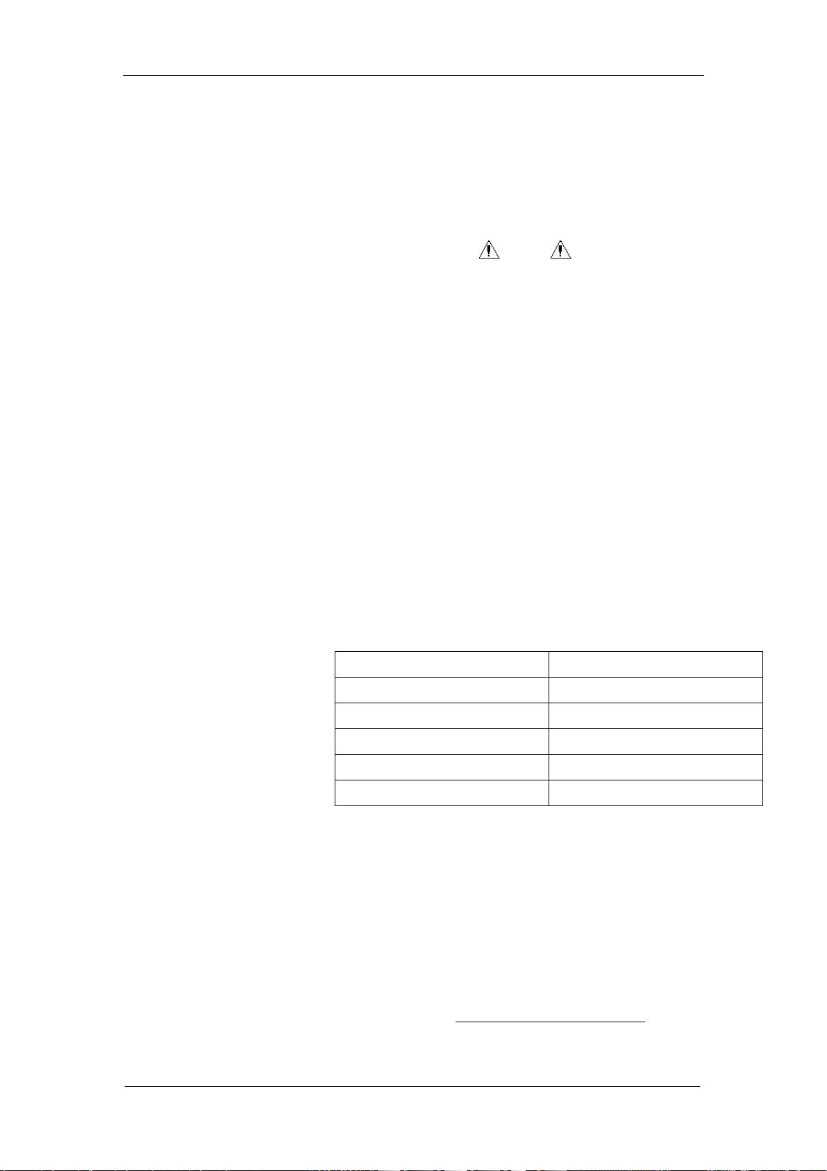
Enter the Calibration Factors
In the menu operation, move the cursor to the
“Calibration/Manual Calibration” and press [ENTER] to
access the manual calibration screen as shown in
below figure.
Press [ENTER] to access the Edit Parameter state.
×
12.8
%3.102
=
Figure 2-1
Press [↑][↓] to select the item and [←][→] to move
the cursor within the item.
Press [0] – [9] to enter numbers.
The “fixed decimal” format is adopted so that the user
need not enter the decimal point.
2-10 Auto Hematology Analyzer Service Manual (V1.1)
Page 37
Troubleshooting
The factor should be within the range of 75% -- 125%.
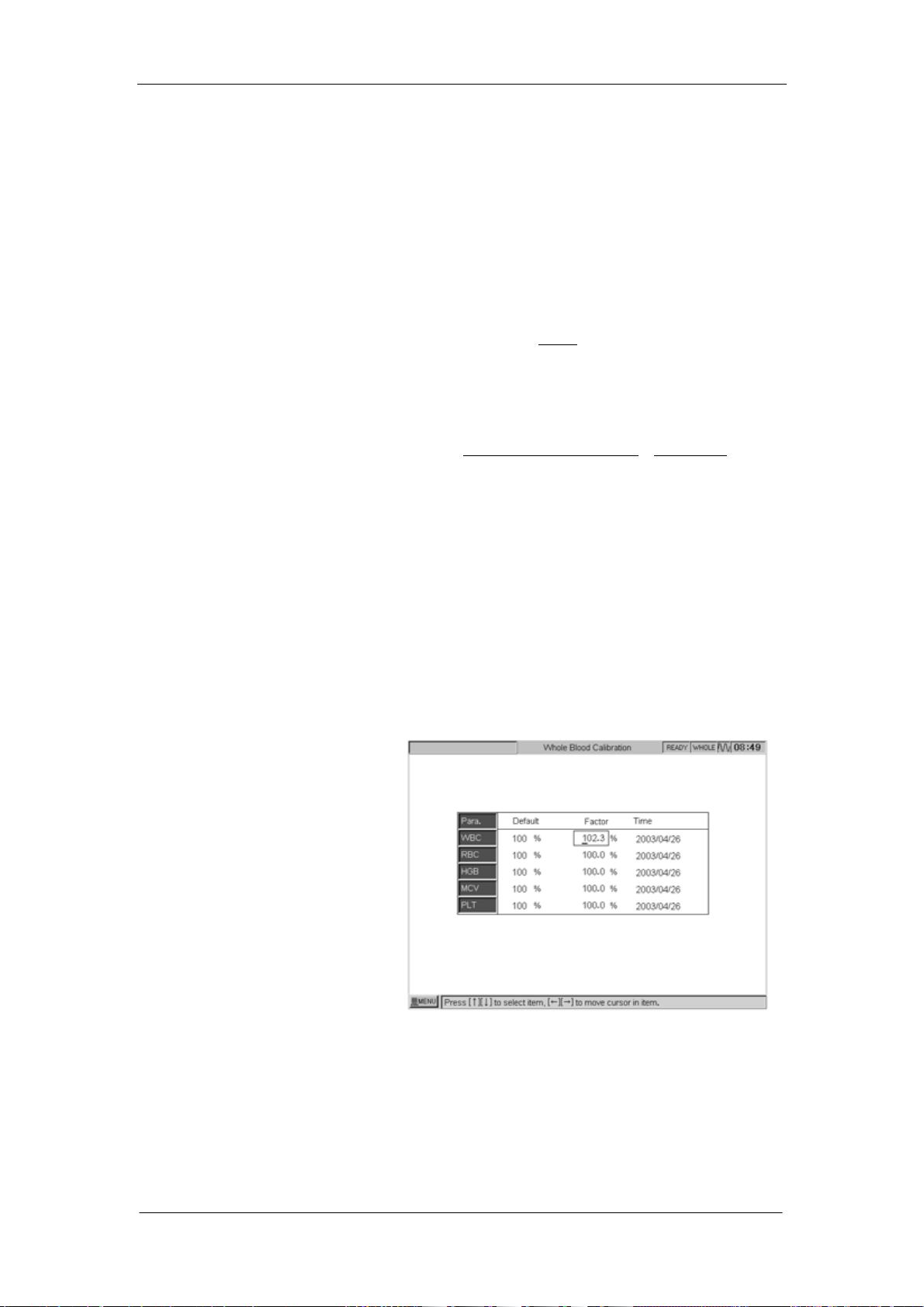
Confirm the New Calibration Factors
After entering the new factors, press [MENU] key to
return to menu operation, then the dialog box pops up
as shown in below figure.
Figure 2-2
Select “Yes”, store the new factors.
Select “Cancel”, reserve the old factors.
Verification
After entering the new factors, run the calibrator in
Count screen. Verify that the results are within the
specified range.
•The Automatic Calibration procedures are:
1. Set up the sample mode to Whole Blood or
Prediluted.
2. Enter the reference value of the calibrator.
3. Run the calibrator.
4. Confirm the calibration factors.
Auto Hematology Analyzer Service Manual (V1.1) 2-11
Page 38

Troubleshooting
Figure 2-3
In menu operation, move the cursor to
“Calibration/Auto Calibration”, press [ENTER] key to
access Auto Calibration screen.
Figure 2-4
Edit the reference:
Press [1] to access “Edit Reference” status. Enter
the reference values of the calibrator.
Press [↑][↓] to select the item and [←][→] to
move the cursor within the item.
Press [0] – [9] to enter numbers.
The “fixed decimal format” is adopted so that the user
need not enter the decimal point.
Press [ENTER] to exit edit status and access the
Count status.
2-12 Auto Hematology Analyzer Service Manual (V1.1)
Page 39

Troubleshooting
A
Figure 2-5
Run Calibrator Procedure
WARNING
WARNING
void contacting with the sample probe.
1. Place the well-mixed calibrator to the probe so that
the tip is well into the tube, and press the [START] to
run. The process of run is the same as that of count.
After running, the screen displays as shown in below
figure.
Figure 2-6
Select “Yes” to validate the results.
Auto Hematology Analyzer Service Manual (V1.1) 2-13
Page 40
Troubleshooting
Select “Cancel” to invalidate the results.
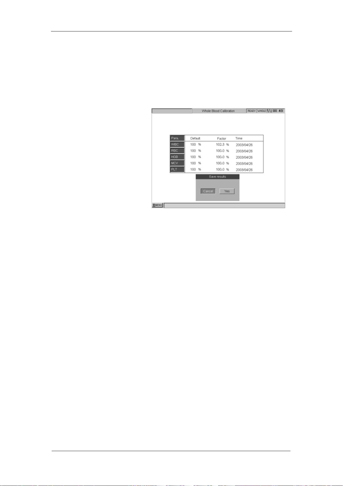
The below figure shows an example of the results after
five times of running.
Figure 2-7
The average value of calibration and the new
calibration factors automatically calculated by the
system are displayed in the right side of the screen.
“***” refers to invalid results, which means that the
average value of the parameter and the calibration
factor are invalid.
Maximum 5 samples can be counted for auto
calibration. The auto calibration result will be displayed
only after 3 samples are counted. If the calibration
factor of a parameter is out the range of 75% ~ 125%,
it will not be displayed, find the reason. If necessary,
contact the Mindray Customer Service Department or
the distributor.
Confirm the New Calibration Factors
Press [MENU] to return to the menu operation. The
dialog box pops up as shown in below figure.
2-14 Auto Hematology Analyzer Service Manual (V1.1)
Page 41

Troubleshooting
Figure 2-8
Select “Yes”, save the new calibration factors.
Select “Cancel”, keep the original calibration factors.
Verification
When the new calibration factors are adopted, count
the calibrator in the Count screen and verify that the
result is within the specified range.
Auto Hematology Analyzer Service Manual (V1.1) 2-15
Page 42

Troubleshooting
2.4 Troubleshooting Erroneous Data
Background Noise
When the count data of a container filled with diluent
just exceeds the tolerable value of the parameter
shown in the table in ”Background Noise Check” of this
chapter, the seven possible causes of error are:
(1) Dirty diluent
(2) Dirty diluent container
(3) Dirty baths
(4) Dirty valves
NOTE
Before storing the instrument for a long time, clean
and empty all fluid tubings in the instrument with
distilled water. Otherwise, the diluent salt adheres
to the baths and cannot be removed easily.
(5) Electronic noise affecting the counting/calculation
circuit:
AC line, backlight converter, peripheral equipment
such as microwave treatment machine, motors in
the instrument
(6) Mechanical noise affecting the counting/calculation
circuit:
Vibration from motor in or around the instrument,
such as a centrifuge
(7) Tubing noise affecting the counting/calculation
circuit:
Liquid flow with some remained electric charges
As a countermeasure to the above 7 causes, take the
following actions.
Cause (1) or (2)
− Replace the diluent with diluent from a sealed
container.
Cause (3) or (4)
− Clean the baths with E-Z cleanser
− Clean the baths with probe cleanser
2-16 Auto Hematology Analyzer Service Manual (V1.1)
Page 43

Troubleshooting
− Clean valves with distilled water
− Exchange the other same model valves to try
Cause (5)
−Securely ground the instrument, including any
optional units such as external printer.
Cause (6)
− Keep the instrument away from the vibration source.
Cause (7)
− Securely ground the tubing.
Auto Hematology Analyzer Service Manual (V1.1) 2-17
Page 44

Troubleshooting
For Reproducibility
This subsection describes the cases when the
reproducibility for the following measuring parameter
or calculated parameter is poor.
− PLT
− HGB
− WBC
− RBC
− Data other than red cell indexes (MCV, MCH and
MCHC)
− RBC and PLT coefficient related parameters
− HCT and MCV
2-18 Auto Hematology Analyzer Service Manual (V1.1)
Page 45
Troubleshooting
Poor Reproducibility for PLT
Possible Cause Countermeasure
The background data on PLT is
Refer to “Background Noise Check“ of this chapter
high
Dirty RBC aperture Clean the aperture.
Dirty RBC bath Clean the bath. Refer to the “Maintenance” of the
operator’s manual.
Dirty measuring tube Clean the tube below the RBC bath
Dirty wipe block Clean the wipe block
Replace a new wipe block
The sample probe position is not
Adjust the probe position using localizer
correct
The 3-way valve (SV11) is dirty Clean the valves
Replace this valve
The 3-way valve (SV11) cannot
Replace the 3-way valve (SV11).
drain liquid empty.
The diuent syringe exists
Remove the bubbles from the syringe
bubbles
Faulty circuit Replace the ANALOG board
Poor Reproducibility for HGB
Possible Cause Countermeasure
Dirty WBC measurement bath Clean the WBC bath with E-Z cleanser or probe
cleanser
The voltage output from the HGB
sensor is not optimal
Adjust the HGB voltage. Refer to “Adjust Gain” of
this manual.
Adjust the adjustable resistance VR3 & VR4 to
adjust the output voltage of HGB to 4.4v-4.6v
The 3-way valve (SV12) cannot
Replace the 3-way valve (SV12).
drain liquid empty.
The 3-way valve (SV12) is dirty Clean or replace the valves
The specified diluent and
Use the correct reagent
hemolysing reagent were not
used
Cyanide in the hemolysing
reagent has been dissolved by
Replace the hemolysing reagent with a new
reagent and tighten the cap of the reagent bottle.
sunlight or heat
The HGB 2.5 mL syringe exists
Remove the bubbles from the syringe
bubbles
The light axis of the HGB LED is
deviated
Adjust the light position
Replace the light
Auto Hematology Analyzer Service Manual (V1.1) 2-19
Page 46
Troubleshooting
The light of HGB is aging Replace the HGB unit
The diuent syringe exists
Remove the bubbles from the syringe
bubbles
Faulty the Analog board Replace the analog board
Poor Reproducibility for WBC
Possible Cause Countermeasure
The background data on WBC is
Refer to “Background Noise Check“ of this chapter
high
Dirty WBC measurement bath Clean the WBC bath with E-Z cleanser or probe
cleanser
Dirty measuring tube Clean the tube below the WBC bath
Dirty wipe block Clean the wipe block
Replace a new wipe block
The sample probe position is not
Adjust the probe position using localizer
correct
The 3-way valve (SV12) cannot
Replace the 3-way valve (SV12).
drain liquid empty.
The 3-way valve (SV12) is dirty Clean the valves
Replace this valve
The lyse reagent has been
dissolved by sunlight or heat
The constant current is not
Replace the lyse reagent with a new reagent and
tighten the cap of the reagent bottle.
Change the transformer or analog board
stable
The diuent syringe exists
Remove the bubbles from the syringe
bubbles
Faulty the Analog board Replace the analog board
Poor Reproducibility for RBC
Possible Cause Countermeasure
The background data on RBC is
Refer to “Background Noise Check“ of this chapter
high
Dirty RBC measurement bath Clean the RBC bath with E-Z cleanser or probe
cleanser
Dirty measuring tube Clean the tube below the RBC bath
Dirty wipe block Clean the wipe block
Replace a new wipe block
The sample probe position is not
Adjust the probe position using localizer
correct
The 3-way valve (SV11) cannot
Replace the 3-way valve (SV11).
drain liquid empty.
2-20 Auto Hematology Analyzer Service Manual (V1.1)
Page 47

The 3-way valve (SV11) is dirty Clean the valves
Replace this valve
The constant current is not
Change the transformer or analog board
stable
The diuent syringe exists
Remove the bubbles from the syringe
bubbles
Faulty the Analog board Replace the analog board
Troubleshooting
Auto Hematology Analyzer Service Manual (V1.1) 2-21
Page 48

Troubleshooting
2.5 Troubleshooting
B
Burn fuse when power on unit AC input power is not stable
Power supply board is short
circuit
Bubbles Bubbles in the sample
Regents are not enough
Setting count time is long
The aperture is broken
Counting channel is leakage
Background testing is
abnormal
C
Counting time is sometimes
too short and sometimes
normal
Clog Big cells or debris in the
D
Diluent injection time becomes
longer, and make WBC bath
full
Display is not clear Backlight is too bright or too
F
Fluctuating and rotatory motor
error
Regents are dirty
Electronic noise
Dirty bath
Dirty valves
The CPU board has some
problem
sample
Setting count time is short
The aperture is blocked
Diluent is not enough
Volumetric board is broken
SV3 valve doesn’t close
properly
dark
LCD screen is old
The environment
temperature is low
Tubing which on the sample
Using a manostat
(voltage regulator)
Replace the power
supply board
Remove the bubbles
Re-prime the regents
Re-set the count time
Change a new aperture
Replace the leakage
parts
Change new regents
Connect ground well
Clean the bath
Clean the valves
Replace the CPU
board
Remove the debris
from the sample
Re-set the count time
Clean the aperture
Check the diluent
syringe and diluent
Replace the
volumetric board
Replace the SV3 valve
Adjust the unique
resistor on the CPU
board
Replace the LCD
screen
Increase environment
TEMP and add UPS
Loose the tubing
2-22 Auto Hematology Analyzer Service Manual (V1.1)
Page 49

Troubleshooting
probe assembly is too tight
The detectors are broken
Replace the two
detectors
H
Hang during initiation
(Initiation stop)
Software has some problem
Power supply board is
broken
Re-install the software
or replace a new
Moduleondisk
Replace power supply
board
HGB always alarm WBC bath is dirty Clean WBC bath
HGB error and WBC clog The 10ml syringe’s piston
Re-fix the piston
falls off
Hematology analyzer leakage
and vacuum is abnormal
HGB background voltage is
abnormal, no chance to make
The tubing of waste
assembly is kink
WBC bath is dirty or HBG
gain is not correct
Release the tubing
and empty the liquid
Dip in the WBC bath
and adjust HGB gain
it down
HGB error HGB background voltage is
abnormal (0-3.2v or
4.9-5.0v), it’s out of
acceptable range
Adjust the HGB gain
or the resistor (VR3
&VR4 which on the
analog board) to
4.2V-4.6V
HGB adjust error HGB background voltage is
abnormal (3.2-3.4v or
4.8-4.9v), it’s out of
acceptable range
Adjust the HGB gain
or the resistor (VR3
&VR4 which on the
analog board) to
4.2V-4.6V
I
Initiation time is too long disk on module is broken Replace hard disk
(disk on module)
K
Keyboard, some buttons no
response
CPU board or keyboard is
broken
Replace the CPU
board or keyboard
L
LCD screen, there is a line on
the screen
CPU board is broken if the
line is a dot line and the
position is fixed
LCD screen is faulty if the
line is a continuous black or
light line
Replace the CPU
board
Replace the LCD
screen
Auto Hematology Analyzer Service Manual (V1.1) 2-23
Page 50
Troubleshooting
LCD screen is dark The color palette setting is
not correct
The backlight is too dark
Re-set the color
palette to 8-color
Adjust the unique
resistor on the CPU
board
Leakage Vacuum chamber is broken,
waste liquid tubing is kink,
tubing leakage
Analog board is broken
The air filters are dirty
Change the vacuum
chamber
Loose the waste liquid
tubing
Check the default
point
Replace a new analog
board
Replace this two fiters
M
mid-size cell’s percent is
sometime too high and
sometime normal
Put the sample to long time
Add too much anti-coagulant
Count the sample in
30mins
Reduce the value of
anti-coagulant
N
No diluent injected Diluent is empty
The piston falls off
No sample inspired and no
SV4 valve doesn’t work Replace the SV4 valve
Change a new bottle
of diluent
Re-fix the piston
diluent injected
No initialization, but exist
backlight and a moment it
The CPU board is broken Replace the CPU
board
becomes black, the indicators
flash like saver
No rinse (diluent, lyse) alarm The rinse (diluent, lyse)
sensor is broken or plastic
washer falls off
Replace the rinse
(diluent, lyse) sensor
or re-fix the washer
No backlight The inverter is broken Replace the inverter
P
PLT/RBC’s result shows “**.*” Test the RBC aperture
Replace the RBC bath
voltage is not stability, the
range is 4.5-11.0V
PLT result is always over 1000 The RBC bath is dirty Clean or replace the
RBC bath
Power-on is normal, but the
screen is black suddenly after
Power supply board and
CPU board are broken
Replace the power
supply board and CPU
2-24 Auto Hematology Analyzer Service Manual (V1.1)
Page 51

Troubleshooting
initiation board
Power-on is normal, but no
display, no initiation, no
The CPU board is broken Replace the CPU
board
response
PLT background is abnormal Connecting ground is not
proper, or with high voltage
Pressure error Pressure pump leakage or
tubing broken
Pressure filters are blocked
Reconnect ground
wire
Replace pump or
tubing
Replace new filters
R
Rotatory motor error The tubing connecting
sample probe is loose, and
Replace the proble
mosule
liquid enters the motor to
make the resistance higher
RBC bath full and liquid
overflows
RBC/PLT’s result shows “**.*” Test the RBC aperture
The V11 valve doesn’t work
or dirty or doesn’t work well
Clean or replace the
V11 valve
Replace the RBC bath
voltage is not stability, the
range is 4.5-11.0V
RBC always clog 1. RBC bath is dirty
2. The count time is a little
longer than the setting
time
3. One of the sensor which
on the MTB board is broken
1. Clean the bath
using E-Z
cleanser or probe
cleanser
2. Re-set the count
time
3. Replace the MTB
board
RBC bath is leakage RBC bath is broken with
Replace the RBC bath
cranny
RBC background and value is
too high
RBC bath is broken with
cranny
Replace the RBC bath
RBC no result Analog board is broken Replace the analog
board
S
Stability is bad, and PLT over
1000 sometime
There are some bubbles in
Diluent syringe and make
Replace the SV3 valve
the injected diluent not
enough
Sample probe leakage SV4 valve is leakage Replace the SV4 valve
Show “8002 error code” The disk on module is
broken
Replace the disk on
module
Show ”48V is low” The transformer or analog Replace transformer
Auto Hematology Analyzer Service Manual (V1.1) 2-25
Page 52
Troubleshooting
board is broken or analog board
T
TEMP is low The environment
temperature is low
Increase the
environment TEMP
V
Vacuum is low Air filters are so dirty
Waste liquid tube is kink
Tube is leakage
Vacuum pump is leakage
Vacuum chamber is leakage
Replace the filters
Loose the tube
Replace one new tube
Replace a new pump
Replace a new
chamber
W
WBC always clog 1. WBC bath is dirty
2. The count time is a little
longer than the setting
time
3. One of the sensor which
on the MTB board is broken
1. Clean the bath
using E-Z cleanser
or probe cleanser
2. Re-set the count
time
3. Replace the MTB
board
WBC bath leakage WBC bath is broken with
Replace the WBC bath
cranny
WBC background and value is
too high
WBC bath full and liquid
overflows
WBC result is not stable WBC bath is broken with
WBC bath is broken with
cranny
The V12 valve doesn’t work
or dirty or doesn’t work well
Replace the WBC bath
Clean or replace the
V12 valve
Replace the WBC bath
cranny
Wipe-block is leakage Wipe-block is old Replace wipe-block
WBC value is too high and
RBC is zero or “***”
Mis-use the Rinse and
diluent
Exchange the two
reagents
WBC clog, no count time WBC aperture clog Clean the aperture
using probe cleanser
WBC differential part is
abnormal, and it’s end point at
WBC channel gain is not
correct
Adjust WBC channel
gain
200fl
WBC bubbles during counting SV8 valve is leakage Replace the SV8 valve
WBC no result Analog board is broken Replace the analog
board
2-26 Auto Hematology Analyzer Service Manual (V1.1)
Page 53

2.6 Alarm
Error Message Possible Cause
Com Error
2.5ml & 50ul Motor Error
10ml Motor Error
Rotatory Motor Error
Fluctuating Motor Error
DC/DC Error
12V Power Error
48V Power Error
WBC A/D Error 1. The CPU board is abnormal.
RBC A/D Error 1. The CPU board is abnormal.
PL T A/D Error 1. The CPU board is abnormal.
WBC Interrupt Error 1. The CPU board is abnormal.
1. The transmission settings between BC-3000PLUS and
the external computer are different.
1. The position optical coupler is abnormal.
2. The driving motor is abnormal.
3. The communication wire of the motor is bad connected.
4. The 2.5ml syringe or/and 50ul syringe is damaged or
the resistance of it has increased.
5. The 2.5ml syringe or/and 50ul syringe is not mounted to
the right position.
1. The position optical coupler is abnormal.
2. The driving motor is abnormal.
3. The communication wire of the motor is bad connected.
4. The 10ml syringe is damaged or the resistance of it has
increased.
5. The 10ml syringe is not mounted to the right position.
1. The position optical coupler is abnormal.
2. The driving motor is abnormal.
3. The communication wire of the motor is bad connected.
4. The motor compone nts loosen or mounted to the wrong
position.
5. The pin clip loosens, if the tubing connecting the sample
probe moves randomly or touches the wall when the
motor operates.
6. The tubing connecting the wipe block is over tightly
fastened.
1. The position of the optical coupler is abnormal.
2. The driving motor is abnormal.
3. The communication wire of the motor is bad connected.
4. The motor compone nts loosen or mounted to the wrong
position.
5. The screw lever is not enough smooth.
1. The DC/DC component is abnormal.
2. The analog signal board is abnormal.
1. The power supply board is abnormal.
2. The analog signal board is abnormal.
1. The power supply part is abnormal.
2. The analog signal board is abnormal.
Troubleshooting
Auto Hematology Analyzer Service Manual (V1.1) 2-27
Page 54

Troubleshooting
RBC Interrupt Error 1. The CPU board is abnormal.
PLT Interrupt Error 1. The CPU board is abnormal.
1. The HGB LED loosens.
2. The HGB unit is bedabbled.
HGB Error
3. The HGB LED is damaged.
4. WBC bath is dirty.
5. Diluent is polluted or exceeds its Exp. date.
1. The HGB LED loosens.
2. The HGB unit is bedabbled.
HGB Adjust
3. Light intensity of the HGB LED is set incorrectly.
4. WBC bath is dirty.
5. Diluent is polluted or exceeds its Exp. date.
Vacuum Filter Error 1. The filter is clogged by dirt.
1. Vacuum pump is damaged.
2. Tubing or vacuum chamber has leaks.
3. Tubing connecting vacuum chamber to sensor loosens
Vacuum Low
or falls off.
4. The valve connecting the vacuum chamber is damaged.
5. The waste container is placed over normal position, or
the waste tubing is too thin or too long, or the waste
tubing cannot drain the liquid smoothly.
1. The environment temperature is over the range
Envir. Temp. Abnormal
15℃~35℃
2. The temperature sensor is abnormal.
1. The count baths or apertures are dirty.
2. There are bubbles in the tubing system.
Background Abnormal
3. The reagents are polluted or exceed their Exp. date.
4. There is clog or bubbles error when test the
background.
1. The WBC aperture is clog or dirty.
2. Foreign object has clogged the WBC bath.
3. WBC reference count time is set up improperly.
4. Optical couplers on the volumetric metering board are
damaged or the values of potentiometers are set
improperly.
5. The liquid cannot flow in the tubing smoothly (pressed,
WBC Clog
bends or clogged by foreign object).
6. Inadequate reagent.
7. Can not form stable surface in WBC metering glass
tube.
8. The tubing has leaks or the vacuum system has
problem.
9. The sample has problem, such as the type and
proportion of anticoagulant is selected improperly or
2-28 Auto Hematology Analyzer Service Manual (V1.1)
Page 55

WBC Bubbles
RBC Clog
RBC Bubbles
Diluent Empty
Rinse Empty
Lyse Empty
Pressure1 Low
Troubleshooting
there is blood clots.
1. WBC reference count time is set up improperly.
2. Optical couplers on the volumetric metering board are
damaged or the values of potentiometers are set
improperly.
3. Inadequate reagent.
4. not form stable surface in WBC metering glass tube.
5. tubing has leaks or the vacuum system has problem.
1. The RBC aperture is clog or dirty.
2. Foreign object has clogged the RBC bath.
3. RBC reference count time is set up improperly.
4. Optical couplers on the volumetric metering boa rd are
damaged or the values of potentiometers are
improperly set.
5. The liquid cannot flow in the tubing smoothly (pressed,
bends or clogged by foreign object).
6. Inadequate reagent.
7. Can not form stable surface in RBC metering glass
tube.
8. The tubing has leaks or the vacuum system has
problem.
9. The sample has problem, such as the type and
proportion of anticoagulant is selected improperly or
there is blood clots.
1. RBC reference count time is set up improperly.
2. Optical couplers on the volumetric metering board are
damaged or the values of potentiometers are
improperly set.
3. Inadequate reagent.
4. Can not form stable surface in RBC metering glass
tube.
5. The tubing has leaks or the vacuum system has
problem.
1. There are no diluent in the diluent container.
2. The liquid sensor is not connected correctly.
3. The liquid sensor is damaged.
1. There is no rinse in the rinse container.
2. The liquid sensor is not connected correctly.
3. The liquid sensor is damaged.
6. There are no lyse in the lyse container.
7. The liquid sensor is not connected correctly.
8. The liquid sensor is damaged.
9. Pressure pump has fault.
10. Tubing, vacuum chamber has leaks.
Auto Hematology Analyzer Service Manual (V1.1) 2-29
Page 56

Troubleshooting
Pressure2 Low
Recorder Out of Paper
Recorder Too Hot
File Error
Bar Code Invalid
Bar Code Com Error
Printer Error
Diluent Expiry
Rinse Expiry
Lyse Expiry
11. Tubing connecting vacuum chamber to sensor loosens
or falls off.
12. The valve connecting the vacuum chamber is damaged.
13. Pressure pump has fault.
14. Tubing, pressure chamber has leaks.
15. Tubing connecting pressure chamber to sensor loosens
or falls off.
16. The valve connecting the pressure chamber is
damaged.
1. There are no papers in the recorder box.
2. The sensor is abnormal.
1. The thermal head is too hot.
2. The sensor is abnormal.
1. The system software is destroyed.
2. The DiskOnModule disk has bad pars.
1. The format of bar code inputted is invalid for
BC-3000PLUS.
1. There are some errors when the bar code scanner
communicates with BC-3000PLUS host.
1. The printer is not connected correctly.
2. There are no papers in the printer.
3. Wrong type printer which BC-3000PLUS does not
support.
1. Diluent exceeds its Exp. date.
2. The diluent Exp.data inputted is incorrect.
1. Rinse exceeds its Exp. date.
2. The rinse Exp.data inputted is incorrect.
1. Lyse exceeds its Exp. date.
2. The Lyse Exp.data inputted is incorrect.
Trouble Possible Cause
1. Operation is not normalized, sample is not completely
mixed up.
2. Sample is heavily polluted.
Poor repeatability
3. Sample is improperly selected (such as the sample has
blood clots).
4. Wipe block is inaccurately positioned.
5. Instrument has interference.
6. Reagents are polluted or exceed their Exp. date.
1. Shielding box of sample bath is not well mounted.
Severe interference
2. Shielding wire of analog signal board is not connected
correctly.
2-30 Auto Hematology Analyzer Service Manual (V1.1)
Page 57

Troubleshooting
3. Valve V11 or V12 connecting count bath is not well
closed or has dirt.
4. The gain is set incorrectly.
5. The input power is unstable.
Power-off during running 1. Unstable input power, it exceeds the protective range.
Auto Hematology Analyzer Service Manual (V1.1) 2-31
Page 58

Page 59

Chapter 3 Hardware
The instrument has the following hardware:
CPU Board
Power Drive Board
Analog Signal Board
Keypad
Recorder Board
Volumetric Metering Board
Power Supply Board
Display Screen
Linear Transformer
Hardware
Auto Hematology Analyzer Service Manual (V1.1) 3-1
Page 60

Hardware
3.1 CPU Board
Function and Modules
The board consists of three modules:
● Computer System Module
With CPU as the core, the computer system module also includes some peripheral
circuits like RTC, WDT, SDRAM, Flash, and Super I/O. The super I/O circuit uses
Super I/O chip as the core and includes other sub-circuits like keyboard, serial port,
parallel port, floppy disk drive interface and IDE interface.
CPU, SDRAM and Flash construct the basic computer system and the basic
environment for the operation of software.
RTC provides calendar and clock.
WDT is designed to protect the system in case the software fails to function. It will
generate reset signal once the software fails to function.
Super I/O provides external interfaces, including one parallel port, two serial ports,
one keyboard interface and one floppy disk drive interface.
● A/D&I/O Module
A/D&I/O module use FPGA and CPLD as the core and include other peripheral
circuits like FIFO, ADC and I/O.
The A/D circuit can convert the analog signal pre-processed by the analog signal
board and then send it to CPU via FIFO.
CPU uses I/O interfaces to manage interrupts, control valves and pumps, control the
gain of analog signal board, and zap function and HGB light.
● Display Module
The display module uses FPGA as the core and includes other peripheral circuits like
SRAM, display interface I/O.
Display module is designed to display the information on the LCD screen.
Block Diagram of CPU Board
3-2 Auto Hematology Analyzer Service Manual (V1.1)
Page 61

Figure 3-1 shows the block diagram of CPU board.
Computer system of
CPU Board
RTC WDT SDRAM Flash SuperI/O
CPU
Hardware
Display module
FPGA
A/D collection
FPGA
I/O port
CPLD
A/D & I/O
Figure3-1
● Computer System
Computer system includes CPU (U33), SDRAM (U1, U2), Flash (U3), RTC (U7),
WDT (U6) and Super I/O (U30).
CPU, SDRAM and Flash make up of the basic computer system. Flash serves to
store BIOS and FPGA configuration data. During initialization, CPU can read the
FPGA configuration data from the Flash in order to set up FPGA. By executing the
startup program in BIOS, CPU can transfer the main program on the DiskOnModule
disk into SDRAM and accordingly run the program.
2
RTC and WDT together use I
RTC. RTC has backup battery, therefore it can run normally even in the shutdown
state. WDT is adopted to provide protective function. It can forcibly reset CPU when
software fails to function.
Super I/O provides external interfaces. The parallel port is for connecting printer.
Serial port 1 may connect bar code scanner. Serial port 2 may realize the
Auto Hematology Analyzer Service Manual (V1.1) 3-3
C bus. CPU may get the current time by accessing
Page 62

Hardware
communication with external computer. The keyboard interface is designed to
connect standard keyboard.
● A/D & I/O
Circuit of this part includes A/D collection and I/O.
A/D sample: this board has three pieces of A/D chips. U37 is a 12-bit A/D to sample
voltages of WBC, HGB and WBC apertures as well as RBC aperture, vacuum,
pressure, 5V supply, +12V, -12V and +48V supplies of analog signal board, and 12V
supply of power board. CPU select channel by using the analog switch on the analog
signal board and saves the data sampled by U37 into U40 and U41. U35 and U36
are 8-bit A/D, used respectively to detect PLT and RBC. The sampled data are
separately saved into U39 and U38. U38~U41 are 8-bit and 2K FIFO. When FIFO is
half-full, it sends interrupt to CPU. CPU can read the data from FIFO via FPGA (U42).
Besides, U42 is used to control the analog signal board, including gain control, zap
control, HGB light and constant-current source control.
● Display Module
The display circuit is made up of FPGA (U43) and VRAM (U47~U49). CPU writes the
display data into VRAM via FPGA. FPGA can generate LCD driving timing. CPU
reads data from VRAM in terms of the driving timing and displays them on LCD.
■ PCB Layout of CPU Board
3-4 Auto Hematology Analyzer Service Manual (V1.1)
Page 63

Hardware
Recorder
Power
Supply
Recorder
Keypad Start
Volumetric
Metering
Valve and
Liquid SensorLCD Interface
Analog Signal
Pump
Drive
3-Wire
Serial
Port
IDE Interface
A/D Control
Signal
Figure 3-2
FDD
Keyboard
PS/2
RS-232C
Serial Port
1
RS-232C
Serial Port
2
Parallel Port
Auto Hematology Analyzer Service Manual (V1.1) 3-5
Page 64

Hardware
3.2 Analog Signal Board
Functions and Modules
The main functions of the analog signal board are
1. Process the original signal into the situation matching the requirement of A/D
conversion;
2. Amplify the weak signal of WBC and RBC/PLT channels to the value between
0.2V-5V;
3. Amplify HGB signal;
4. Monitor the environmental temperature;
5. Monitor the pressure and vacuum in chambers;
6. Monitor the accessorial power supplies.
The analog signal board includes the following modules:
1. RBC/PLT and WBC amplification circuit: blood cells count channel, including WBC
unit and RBC/PLT unit. This circuit can amplify the WBC and RBC/PLT signals by
using multistage AMP and band-pass filters. Every channel in this circuit uses digital
potentiometer to adjust the AMP multiple. There is voltage-limited protective output
at the end stage of output circuit;
2. HGB measuring circuit: amplify HGB signal via using current-voltage conversion
and voltage AMP circuit. At the same time, it acts as the constant-current driver
circuit for the LED when measuring HGB. The output current of this circuit is
adjustable between 5-25mA. ON/OFF of the constant-current source is controlled by
optical coupler. This circuit uses digital potentiometer to adjust the AMP multiple;
3. Pressure measuring circuit: This circuit can transfer the changes of vacuum and
pressure into voltage signal by pressure sensor, then amplify this signal and send it
to A/D converter on CPU board to acquire digital signal. The AMP circuit uses
AD620. The adjustable resistors are placed at the output and the feedback loop of
the AMP circuit to adjust the zero point and full-scale output range of pressure
measurement;
4. Temperature measuring circuit: use thermistor to monitor the environmental
temperature. The changes of the thermal-sensitive resistor is amplified by AD620
and then output to CPU board;
3-6 Auto Hematology Analyzer Service Manual (V1.1)
Page 65
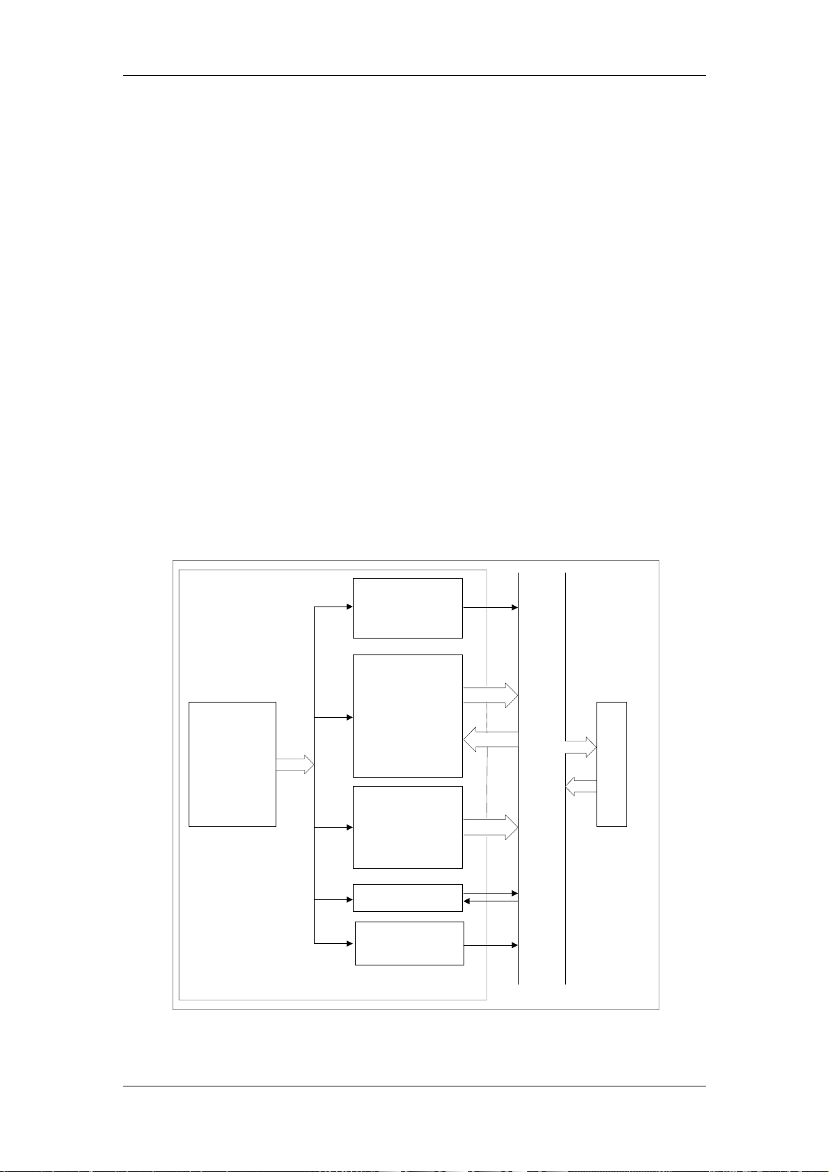
Hardware
5. Power supply circuit: provide +48V DC, 120V AC and ±12V supplies. The ±12V
supply is realized by using the DC-DC module with +5V input. The +48V circuit
provides constant-current source necessary for RBC/PLT measurement. The 120V
AC circuit provides the necessary voltage to zap the apertures;
6. Multiplexer circuit: supply the function that multiple-way signals can be transmit
through the same A/D channel. Use multiplexer to control the sequence of
multiple-way output signals to CPU board. The signal controlling the analog switch
comes from CPU board.
7. Supply monitoring circuit: monitor +48V and ±12V voltages. Obtain the desired
amplitude of the output signal by using resistor to divide voltages.
Block Diagram of Analog Signal Board
The block diagram of analog signal board is shown in figure 3-3.
Pressure Module
Vacuum Signal
Pressure Signal
Hematocyte Signal
Module
Power Supply
Module
+12V
-12V
+48V
120VAC
WBC Signal
RBC Signal
PLT Signal
WBC-HOLE Signal
RBC-HOLE Signal
Monitor Module
+48V Monitor
+12V Monitor
-12V Monitor
HGB Signal Module
CPU Board
Temperature
Monitor Module
Figure 3-3
Auto Hematology Analyzer Service Manual (V1.1) 3-7
Page 66

Hardware
● WBC and RBC/PLT AMP Module
The circuits of three AMP channels WBC, RBC and PLT are basically the same
except difference on small points. RBC and PLT channel uses the first two stages of
AMP circuit and is separated from each other since the third stage. The following
description uses WBC channel as the example.
The input signal is AC signal from uV to mV grade. Therefore using capacitors to
filter direct current signal and connect the AMP channel at the preliminary stage. The
preliminary stage AMP uses U14 to amplify the signal. At the end of this stage,
passive RC circuit is applied to realize high-pass filter. The second stage AMP uses
U15. Its feedback loop is the same as the first stage. It uses parallel-connected
capacitors to realize low-pass filter. The third stage AMP uses U10. Its feedback loop
adopts electronic potentiometer U19, which is controlled by CPU board so that circuit
of this stage can provide different AMP multiples and realize the adjustable
program-controlled gain. Besides, a voltage regulating tube is connected to the
circuit of this stage to protect U19 from being damaged due to too high voltage. A
passive RC circuit is connected at the end of this stage to finish high-pass filter. After
amplifying the signal to the value within the required range, use U11 to realize active
RC filter circuit in order to realize low-pass filter as well as limit the band width of the
signal within the required range. At last the circuit outputs the signal that has passing
circuit of removing negative pulse and buffer circuit.
● HGB Measuring Module
The input signal of HGB circuit is current signal. Before amplifying the signal, the
current signal shall be first converted into voltage signal. OP AMP U27 is adopted to
construct this circuit. The circuit uses classical current-voltage converting circuit.
Resistor is connected into the feedback loop in order to convert current signal into
voltage signal. A capacitor is parallel connected into the feedback loop to realize
low-pass filter. After converting the current signal into voltage signal, input the
voltage signal into the voltage AMP stage. U28 is used to realize the AMP circuit.
Adjustable resistor is connected into the feedback loop in order to adjust the AMP
multiple. Besides, a zero adjusting circuit is connected to the input end via an add
circuit in order to ensure that when the input is zero the input signal of the circuit has
positive voltage. An adjustable resistor is used to control the output of zero point.
● Pressure Monitor Module and Temperature Monitor Module
Both pressure measuring and temperature measuring circuits use instrumentation
amplifier to amplify the signal. The circuits for measuring pressure and temperature
3-8 Auto Hematology Analyzer Service Manual (V1.1)
Page 67

Hardware
are basically the same. The following description uses pressure measuring circuit as
the example.
The circuit uses U25 to construct the constant current source to power the pressure
sensor. The pressure sensor has bridge circuit. Its output signal is transmitted into
U20 by means of difference. U20 can adjust the AMP multiple via the adjustable
resistor at its R
pin so as to amplify and output the signal. Additionally, an adjustable
g
resistor is connected to the output of the pressure measuring circuit to adjust the
zero output of the pressure sensor.
● Power Supply Monitor
The ±12V voltage powering the analog circuit is converted from +5V voltage. This
part is realized by using DC-DC module U30. Add a LC filter circuit at the end output
of the power supply to reduce its ripple.
On this board, relay is used to control ON/OFF of the 120V AC so as to zap the
apertures.
+48V voltage is converted from the 53V AC voltage. This part first uses DB104 to
implement DC conversion, then use U29 to obtain the +48V DC voltage. Optical
coupler is used to control ON/OFF of the supply.
The monitor circuit adopts the form of voltage-division with resistor. Its output is
transmitted to the CPU board by a follower. The power supplies to be monitored are
+48V and ±12V.
Auto Hematology Analyzer Service Manual (V1.1) 3-9
Page 68

Hardware
3.3 Power Drive Board
Functions and Modules
The power drive board is designed to control the rotatory motor, fluctuating motor and
syringe motors. Besides, it also receives the switch signal from the host to control the
pump and valve. The power board has three modules: ON/OFF control module, motor
control module and power supply module.
The ON/OFF control module consists of optical coupler isolation circuit, valve driving
circuit and pump driving circuit.
Optical coupler isolation circuit: isolate the parallel ON/OFF signal coming from the host;
eliminate the interference of large current signal to the front-end control circuit.
V alve driver circuit: realize power driving function for 18-way valves; the driving current is
1.5A and the driving voltage is 12V.
Pump driver circuit: realize power driving function for 4-way pumps, the driving current of
three ways is 1.5A and the driving current of the other way is 3A. The driving voltage is
12V.
Motor control circuit: it consists of serial port communication circuit, program control
circuit, current-limiting circuit, motor driving circuit and protective circuit.
Serial port communication circuit: realize serial port communication with the host, the
signal level is compliable with RS232 serial port. According to the requirement for
isolation, the communication between the host and the module is isolated by using
optical coupler. Besides communication management circuit is used to realize
multi-machine communication management.
Program control circuit: control the rotatory motor, fluctuating motor, and 10ml syringe
motor and 2.5ml&50µl syringe motor according to the command from the host. Three
53-series CPUs are used to realize the control. At the same time, receives information of
received command and returns the executed results to the host.
Current-limiting circuit: use constant current to control the syringe motor and the
3-10 Auto Hematology Analyzer Service Manual (V1.1)
Page 69

Hardware
fluctuating motor in order to obtain good results.
Motor driver circuit: drive the step motor. The driving current of each phase should be 1A.
Protective circuit: Because the motor is inductive load, protective circuit should supply
continuous current for it.
Power supply module: provide +7.2V and +5V supplies to respectively power of the
recorder and the power board.
Block Diagram of Power Drive Board
Figure 3-4
● Switch Control Module
The control signals of 18 ways valves and 4 ways pumps are transmit to the power
board through parallel port. 7 optical couplers are used to isolate the digital supply
from the driving supply in order to avoid the interference of big current on the
Auto Hematology Analyzer Service Manual (V1.1) 3-11
Page 70

Hardware
front-end circuit. The circuit driving the valve uses ULN2068B as the driver chip. Its
driving voltage is 12V. The maximum driving current of each valve is 1.5A.
Similar to the circuit driving the valve, the circuit driving the pump also uses
ULN2068B as the driver chip. Their difference lies in that a pump with big power
consumption uses transistor Q1 to amply the current in order to obtain 3A driver
current.
The control logic level is TTL, which is valid at low level. It means when the input
signal is “0”, the corresponding pump or valve is connected through.
● Motor Control Module
Receive the command from the host via serial port under the control of serial port
communication and management circuit. For serial port communication circuit, the
optical coupler isolation OP7 and OP8 as well as level transition U10 are adopted to
realize isolation and level transition. Besides, U28 is applied to manage the
communication circuit so as to realize multi-machine communication.
The 4-step motors are controlled by three modules which U21 controls the rotatory
and fluctuating motor in order to control the sample probe assembly. The rotatory
motor uses constant-voltage full step driver way while the fluctuating motor adopts
constant-current half-step driver way. In addition, U26 and U27 are used to control
the motors of 10ml syringe and 2.5ml&50µl syringe by means of constant-current
half-step drive.
The driving circuit of rotatory motor uses optical coupler isolation and is driven by U9.
U15 acts to drive the fluctuating motor and syringe motors. Its output can be 2A per
phase.
Current-limiting circuit and voltage protective circuit are realized respectively by
L6506D and UC3610. The setup limit current is 1A. The driving voltage of motor
shouldn’t exceed 50V.
● Power Supply
Provide +5V for power board. U29 is used to realize the constant-voltage output and
Q2 for amplifying the current. The maximum current that can be pr ovided is 4.5A.
The internal control supply of the power board is realized by LM7805.
3-12 Auto Hematology Analyzer Service Manual (V1.1)
Page 71
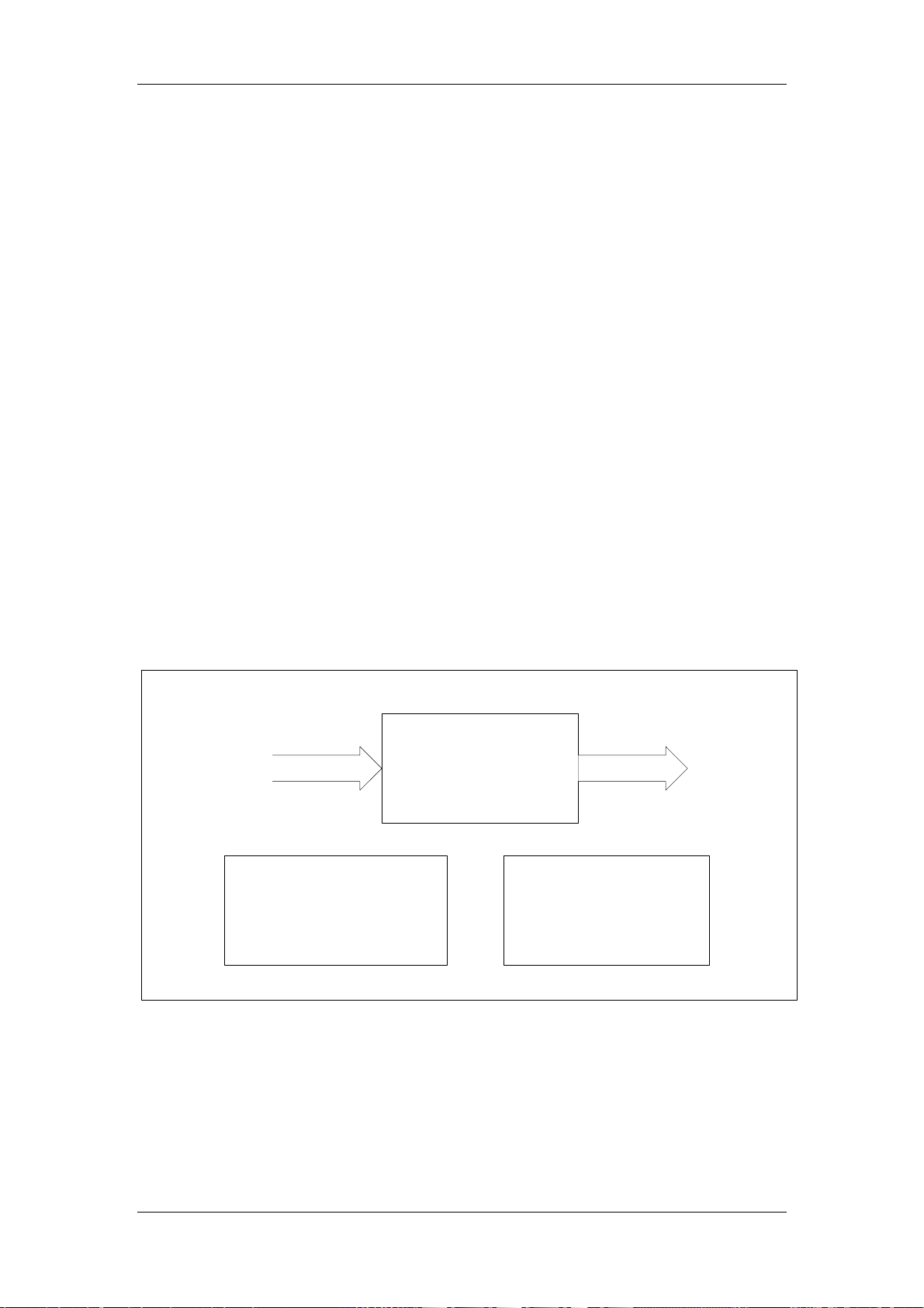
Hardware
3.4 Keypad
Functions and Modules
The keypad circuit may not only support the input via man-machine interface but also
control the buzzer and LCD backlight. The main circuit modules are:
1. Key matrix: the key matrix circuit I0~I6, O0~O3 make up of 7×4 key matrix. There
are totally 23 keys on the keypad. When single key is pressed, only a unique pair
between I0~I6 and O0~O3 are connected through to identify the key function.
2. Circuit for controlling LCD backlight: this circuit first uses a piece of 7805 to obtain
the constant 5V supply. Then it can acquire the voltage used to control the backlight
brightness through using 2 resistors with fixed resistance and an adjustable resistor.
The voltage-division range is between 1V ~ 3V. LCDBCTL signal is used to control
the existence of backlight.
3. Buzzer: use control signal I7 and a dynatron to control the buzzer.
Block Diagram of Keypad
I0厖 I6
Key Matrix
Circuit for controlling
Buzzer circuit
LCD backlight
O0厖 O3
Figure 3-5
Auto Hematology Analyzer Service Manual (V1.1) 3-13
Page 72
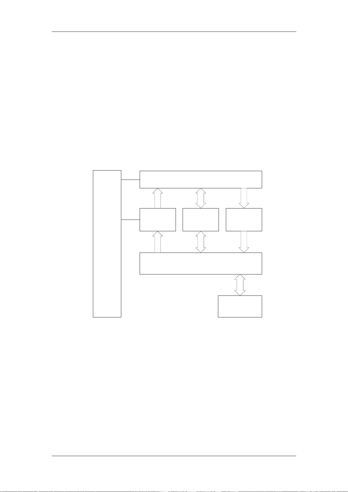
Hardware
3.5 Recorder Board
Functions and Modules
The main function of the recorder board is to receive the data from the CPU board via
serial port, process them and send them to the thermal head. At the same time, it drives
the motor of the thermal head to feed paper so that the received data can be printed out
in the form of characters or graphs.
Block Diagram of Recorder Board
Thermal Head
Motor
Driver
CPLD
9536
Status
Detection
DC/DC
12V>8V
CPU
Signal & 5V
Figure 3-6
● Thermal head
The thermal head, the core component in the recorder, is the PTMBL1306A thermal
head, manufactured by the ALPS company.
● CPU system
The CPU system is the core of the drive board. Its task is to receive the data from the
host and generate lattice messages after calculation using a specified algorithm. These
messages are then sent to the thermal head to be printed out. The CPU system can
simultaneously collect data from both thermal head and drive board and display data
sent to the host.
3-14 Auto Hematology Analyzer Service Manual (V1.1)
Page 73

Hardware
● Power conversion
The recorder requires the system to provide two voltages: 12 V and 5 V. The 5 V is
directly driven by the logic and analog circuit of the drive board and the thermal head. Its
current is less than 150 mA. The 12 V is converted into 8 V (by the DC/DC on the board)
to drive the thermal head and he motor. The current required is determined by the
printing content and ranges from 0.5 A to 2 A.
● Motor drive
A small motor is used to control the p aper movement at the thermal head. The processor
on the drive board uses two motor drives IC LB1843 V to control and drive the motor.
These two IC’s use constant current to control and drive the motor.
● Status detection
To correctly and safely control and drive the thermal head and the motor, the drive board
must use the sensor inside the thermal head to detect the following signals: the position
of the chart paper, if the paper is installed and if the temperature of the thermal head has
exceeded the limit.
● Key Test Points
NO. NAME LOCATION FUNCTION
1 12 V JP3.1 Power input, range: 10~18 V
2 GND JP3.2 Power and signal ground
Power supply for heating thermal head
3 VPP U7.8
and drive motor: 7.8 V~8.4 V
4 VCC U1.14 +5 V supply: 4.75~5.25 V
CPU reset signal. At high level(>2.4 V)
5 RESET U3.10
after power-on
Auto Hematology Analyzer Service Manual (V1.1) 3-15
Page 74

Hardware
3.6 Volumetric Metering Board
Functions and Modules
The volumetric metering board can calculate liquid volume with the help of volumetric
tube and optical coupler. It is used to ensure the accuracy of WBC and RBC/PLT count.
The volumetric metering board has two channels: WBC channel and RBC/PLT channel.
Each channel consists of one volumetric tube and two optical couplers. When the system
starts counting, the liquid starts flowing in the volumetric tube. When the liquid is passing
through the first optical coupler, the comparator outputs signal of starting count. After the
liquid is passing through the second optical coupler, the comparator outputs the signal of
stopping count. In this way we can know the time when the system starts and stops
counting process.
The circuit has four parts:
1. Circuit for driving optical coupler: provide driving current for the four optical couplers.
Besides, its activity is controlled by CPU board in order to decide whether the optical
coupler works.
2. Circuit for detecting signal of optical couplers: this circuit collects the signal of voltage
variation when the liquid is flowing through the optical coupler and then transmit the
signal to the subsequent circuit.
3. Circuit for generating comparative level: generate the comparative threshold level of
the comparator.
4. Circuit for outputting comparative signal: compare the voltage output from the circuit
for detecting signal of optical coupler with the comparative threshold and accordingly
output start count or stop count signal.
Block Diagram of Volumetric Metering Board
Circuit
for
Detect circuit for WBC start
count optical coupler
Detect circuit for WBC end
count optical coupler
Circuit for generating
comparative voltage
Circuit for generating
comparative voltage
Circuit for outputting
comparative signal
Circuit for outputting
comparative signal
driving
optical
couplers
Detect circuit for RBC/PLT
start count optical coupler
Circuit for generating
comparative voltage
Circuit for outputting
comparative signal
Detect circuit for RBC/PLT
end count optical coupler
Circuit for generating
comparative voltage
Circuit for outputting
comparative signal
Figure 3-7
3-16 Auto Hematology Analyzer Service Manual (V1.1)
Page 75

Hardware
● Circuit for Driving Optical Couplers
To obtain the same light intensity of the four optical couplers, we need to use uniform
constant-current sources. The source is made up of U3 and resistor with the output
range of 5~25mA. CPU board generates signal to control the optical couplers. This
signal is isolated from Q1 by an optical coupler.
● Circuit for Detecting Signal of Optical Couplers
The detecting signal is output from the receive terminal of the optical coupler. Use
potentiometer to adjust the output voltage so that the output voltage of the detecting
signal of the optical coupler can be 2.5V.
● Circuit for Outputting Comparative Signal
Connect U11 with the comparator to form hysteresis comparator with the hysteresis
difference set to 0.25V. Moreover, a LED is added into this part to serve as the indicator.
LED lighting on means the optical coupler has detected liquid.
Auto Hematology Analyzer Service Manual (V1.1) 3-17
Page 76
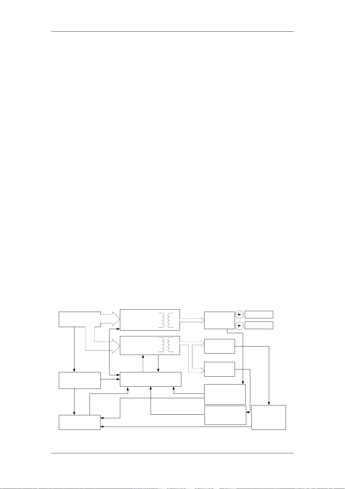
Hardware
3.7 Power Supply Board
General
This power supply is designed for use only on BC-3000PLUS hematology analyzer.
There are two types of power supply board, one input power is AC220V±20% and
another input power is AC110V±20%.The outputs of rating load are +5V& 3Amax,
+12V&3Amax and +32V&1A. The outputs of maximum load are +5V& 7Amax,
+12V&6.5Amax and +32V&3A peak. The outputs of the three ways are isolated from
each other in order to reduce the noise interference.
Working Principle
The two types power supply boards have the same working principle. The power supply
board filters and rectifies the input AC supply in order to obtain a smooth DC volt age with
the amplitude about 1.2 times of the input AC voltage. At the same time, the input AC
supply provides a startup voltage for U2 control chip to control the supply converter. U2
controls the on/off of the main switch through monitoring the voltage and current of the
+12.5V and +5V feedback circuits in order to stabilize the output of +12.8V and +5V. In
addition, the turn ratio of the transformer is used to stabilize the +30V output.
At the same time, this power supply has over-voltage and under-voltage protecting
functions for +12.8V, +5V and +30V. On the primary side, after the power supply
becomes stable, the transformer will provide the VCC necessary for U2.
Block Diagram of Power Supply Board
AC inpu t , filte r an d
rectification
Startup circuit and
auxiliary power
supply
Shutdown
circuit
DC-DC isolation
and conversion
circuit
DC-DC isolation
and conversion
circuit
UCC3810 PWM
control circuit
+12.8V filter
and output
+30Vfilter and
output
+5V fil te r a n d
output
+12.8V feedback
and over/under-
voltage detection
+5Vfeedback and
over/under-voltage
detectio n
+12V output
+12V output
+30Vfeedback
and over/under-
voltage
detection
Figure 3-8
3-18 Auto Hematology Analyzer Service Manual (V1.1)
Page 77

Hardware
Difference Between Two Types Power Supply Board
The difference between the two types power board is the rectification circuit. The figure
3-9 is the 220V input rectification circuit and the figure 3-10 is the 110V input rectification
circuit. The difference on PCB layout is if there is a connection wire between BD1 and
the joint of C5 and C6 as shown in figure 3-10.
Figure 3-9
Figure 3-10
Do not confuse the type of the power supply board otherwise lead
to the instrument damage or body hazard.
Auto Hematology Analyzer Service Manual (V1.1) 3-19
Page 78

Page 79

Chapter 4 Hydraulic System
4.1 Hydraulic System Block Diagram
Hydraulic System
1718
78
3
1
24
10
2
6
Figure 4-1 Hydraulic System Block Diagram
Auto Hematology Analyzer Service Manual (V1.1) 4-1
Page 80

Hydraulic System
4.2 Units of Hydraulic System
■ Sensor Unit
This part is made up of front bath, aperture, rear bath, electrodes and seal washer. This
part is the most important for the whole instrument. Simply speaking this part is a sensor.
Most measuring results are generated by this part.
■ HGB Unit
This part is used to measure the hemoglobin concentration.
■ Dilute Unit
This part consists of 4 step motors (rotatory motor, fluctuating motor and two syringe
driving motors), 2 syringes (10ml and 50ul), wipe block and sample probe. It is used to
aspirate and dilute the sample and clean the system.
■ Volumetric Unit
This part implements the function of measuring the volume; we can calculate the
concentration of blood cells with the number of pulses and the value of volume. This part
is mainly made up of glass tubes and optical couplers.
■ Vacuum Unit
V acuum is the impetus to drive the counting process of hematology analyzer. It is made up
of vacuum chamber, valves and vacuum pump.
■ Pressure Unit
The pressure of this part is provided by pressure pump.
It has the function of mix-up dilution.
■ Auxiliary Unit
This part mainly refers to the connecting tube, connectors and valves which are mainly
used for connection
4-2 Auto Hematology Analyzer Service Manual (V1.1)
Page 81

Hydraulic System
4.3 Whole Blood Count Cycle
In whole blood mode, press the “Start” key, the system transmits “Start Count” request to
CPU, which will feedback the response signal.
1. The 50ul syringe aspirates 13ul of EDT A-K2 anticoagulant whole blood into the probe.
The instrument reads HGB blank. The WBC bath rinses and drains. The 10ml syringe
dispenses diluent into the WBC bath to prefill it.
2. The probe moves to the WBC bath and the 10ml and 50ul syringes dispense the
sample (13ul) and diluent into the WBC bath, making a 1:269 dilution.
3. The 50ul syringe aspirates 15.6ul of the 1:269 dilution into the probe for the RBC/PLT
dilution. The RBC bath rinses and drains. The 10ml syringe dispenses diluent into the
RBC bath to prefill it.
4. The 2.5ml syringe sends 0.5ml lyse reagent to the WBC bath for a final 1:308 dilution,
while the 10ml and 50ul syringes dispense 15.6ul of the 1:269 dilution and additional
diluent into the RBC bath for a final RBC/PLT dilution of 1:44833.
5. Mixing bubbles enter the baths to mix the bath contents. The vacuum chamber
drains.
6. Both dilutions (WBC and RBC/PLT) are drawn through the apertures via regulated
vacuum.
7. The instrument counts 500ul dilution for WBCs and counts 300ul dilution for RBCs
and PLTs. After counting finishes, the flow ends.
8. The system takes an HGB sample reading.
9. The system analyzes the data while the WBC and RBC baths drains and rinses.
10. The system zaps the apertures and the probe moves to the aspirating position. The
system displays results on the screen.
11. The system is ready for the next sample.
Auto Hematology Analyzer Service Manual (V1.1) 4-3
Page 82

Hydraulic System
4.4 Flow Charts of Main Procedures
4.4.1 Power on
Power on
Information about last
shutdown
Abnormal
Startup sequence of
abnormal shutdown
Y
Ready to count
Normal
Startup sequence of
normal shutdown
Background Check
Pass
N
Abnormal background error
Ready to count
Empty tubing
Startup sequence after
empty tubing
Y
N
Count time < 2
Y
Clog: Clog moving sequence
Bubbles: Cleaning sequence
End
Figure 4-2 Power On
4-4 Auto Hematology Analyzer Service Manual (V1.1)
Page 83
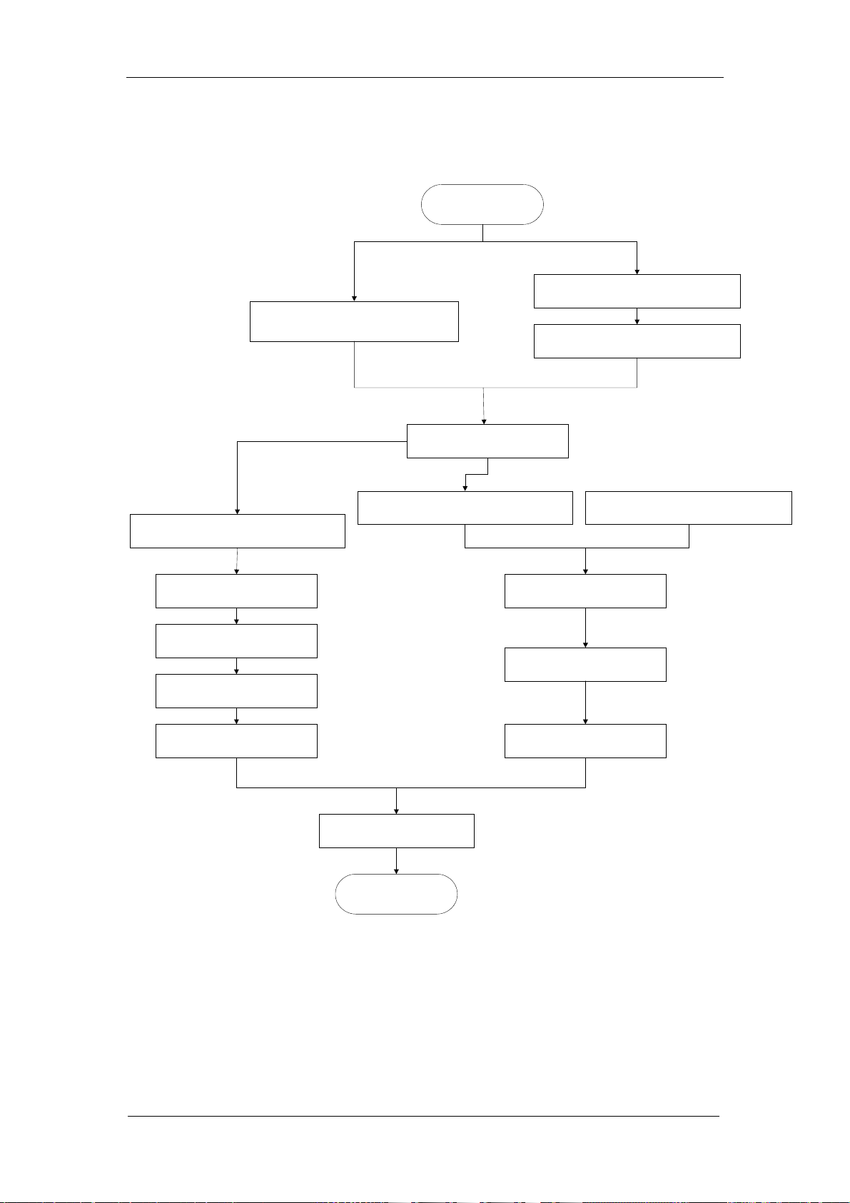
4.4.2 Whole Blood Count
Hydraulic System
Whole Blood Count
Read HGB blank
50ul syringe aspirate 13ul blood sample
Add 0.5ml lyse reagent to the WBC bath
1:308 dilution
in WBC bath
WBC Count
Read HGB sample
Rinse and drain WBC bath
Dispense d iluent prefill the WBC bath
1:269 dilution in WBC bath
50ul syringe aspirate 15.6ul blood dilution
1:44833 dilution in RBC bath
RBC/PLT Count
Rinse and drain RBC bath
Dispense d iluent prefill the RBC bath
Rinse WBC bath
Zap the apertures
End
Rinse RBC bath
Figure 4-3 Whole Blood Count
Auto Hematology Analyzer Service Manual (V1.1) 4-5
Page 84

Hydraulic System
4.4.3 Prediluted Count
Well-mixed 1:80 prediluted
sample
10ml syringe aspirate 0.7ml 1:80
prediluted sample
Prediluted Mode Count
Rinse and drain WBC bath
Dispense d iluent prefill th e WBC bath
1:366 dilution in WBC bath
Read HGB blank
Add 0.36ml lyse reagent to the WBC bath
1:407 dilution
in WBC bath
WBC Count
Read HGB sample
Rinse WBC bath
50ul syringe aspirate 24.8ul blood dilution
1:44274 dilution in RBC bath
Zap the apertures
End
Rinse and drain RBC bath
Dispense diluent prefill the RBC bath
RBC/PLT Count
Rinse RBC bath
Figure 4-4 Prediluted Count
4-6 Auto Hematology Analyzer Service Manual (V1.1)
Page 85

4.4.4 Startup
Clean WBC bath
Clean RBC bath
Hydraulic System
Startup
Create positive pressure in
vacuum chamber
Flush WBC and RBC
apertures
Clean WBC bath
Clean RBC bath
Clean WBC bath
Clean RBC bath
Check background
End
Restore the pressure to normal
state in vacuum chamber
Figure 4-5 Startup
Auto Hematology Analyzer Service Manual (V1.1) 4-7
Page 86
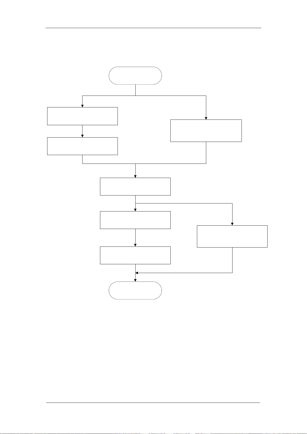
Hydraulic System
4.4.5 Flush Apertures
Empty WBC bath
Empty RBC bath
Flush Apertures
Create positive pressure in
vacuum chamber
Flush WBC and RBC
apertures
Clean WBC bath
Adjust pressure in
vacuum chamber
Clean RBC bath
End
Figure 4-6 Flush Aperture
4-8 Auto Hematology Analyzer Service Manual (V1.1)
Page 87

4.4.6 Dispense Diluent
10ml syringe aspirates 1.6ml
10ml syringe primes 1.6ml
Dispense Diluent
diluent
diluent to the cup
Exit dispense diluent
Hydraulic System
N
Y
Clean the sample probe
End
Figure 4-7 Dispense Diluent
Auto Hematology Analyzer Service Manual (V1.1) 4-9
Page 88

Hydraulic System
4.4.7 Shut Down
Shutdown
10ml syringe aspirates 1.6ml E-Z
cleanser by sample probe from
vial
Empty WBC and RBC baths
Add diluent and 0 .8ml E-Z
cleanser from sample probe to
WBC bath
Add diluent and 0 .8ml E-Z
cleanser from sample probe to
RBC bath
Prime the volumetric glass tubes
with E-Z cleanser from the WBC
and RBC baths
Add diluent to WBC bath
Add diluent to RBC bath
10ml syringe moves to the end
position
End
Figure 4-8 Shut Down
4-10 Auto Hematology Analyzer Service Manual (V1.1)
Page 89
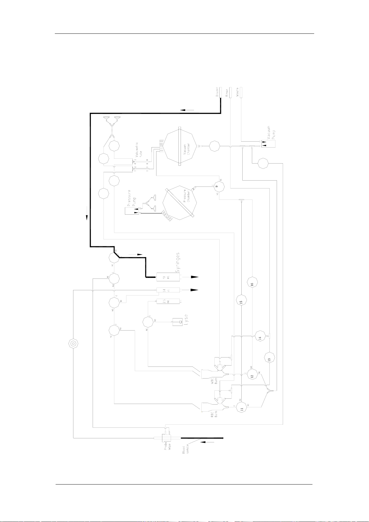
4.5 Hydraulic System Flow Diagram
4.5.1 Inspire Sample and Diluent (Whole Blood Mode)
Hydraulic System
1718
78
3
1
24
10
2
6
Figure 4-9 Inspire Sample and Diluent (Whole Blood Mode)
Auto Hematology Analyzer Service Manual (V1.1) 4-11
Page 90

Hydraulic System
4.5.2 Inspire Sample and Diluent (Prediluted Mode)
18 17
87
10
2
3
1
42
6
Figure 4-10 Inspire Sample and Diluent (Prediluted Mode)
4-12 Auto Hematology Analyzer Service Manual (V1.1)
Page 91

4.5.3 WBC Injection & Lyse Preparation
Hydraulic System
1718
78
3
1
10
2
6
24
Figure 4-11 WBC Injection & Lyse Preparation
Auto Hematology Analyzer Service Manual (V1.1) 4-13
Page 92
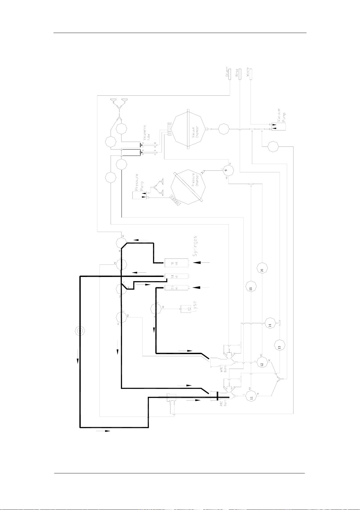
Hydraulic System
4.5.4 RBC & Lyse Injection
18 17
87
10
2
3
1
42
6
Figure 4-12 RBC & Lyse Injection
4-14 Auto Hematology Analyzer Service Manual (V1.1)
Page 93

4.5.5 Mixture
Hydraulic System
1718
78
3
1
10
2
6
24
Figure 4-13 Mixture
Auto Hematology Analyzer Service Manual (V1.1) 4-15
Page 94

Hydraulic System
4.5.6 Count Cycle
17
7
18
8
3
1
42
10
2
6
Figure 4-14 Count Cycle
4-16 Auto Hematology Analyzer Service Manual (V1.1)
Page 95

4.5.7 Cleaning
Hydraulic System
17
7
18
8
3
1
10
2
6
24
Figure 4-15 Cleaning
Auto Hematology Analyzer Service Manual (V1.1) 4-17
Page 96
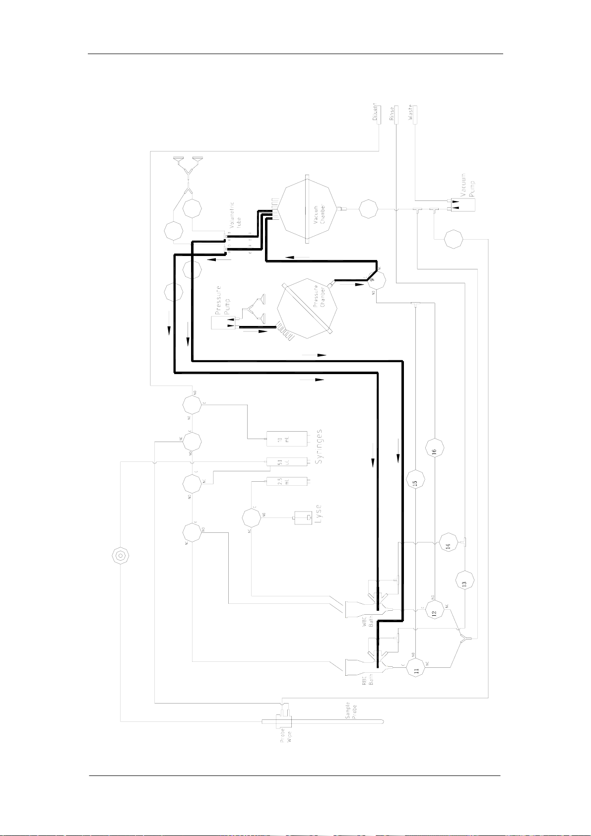
Hydraulic System
4.5.8 Flush
17
7
18
8
3
1
10
2
6
24
Figure 4-16 Flush
4-18 Auto Hematology Analyzer Service Manual (V1.1)
Page 97

4.5.9 Empty Tube
Hydraulic System
17
7
18
8
3
1
42
10
2
6
Figure 4-17 Empty Tube
Auto Hematology Analyzer Service Manual (V1.1) 4-19
Page 98

Page 99
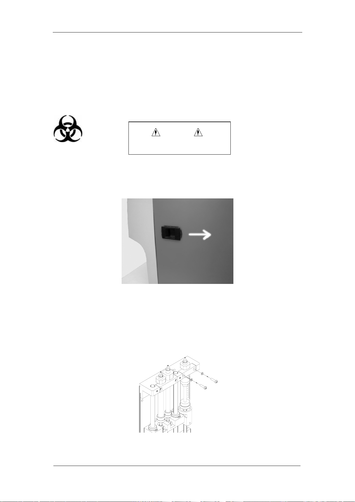
System Structure
Chapter 5 System Structure
5.1 Disassemble/Replace Parts and Components
5.1.1 Disassemble Syringe and Replace Piston
WARNING
Potential biohazard
It is unnecessary to remove the syringe assembly from the instrument.
Push the switch as shown in figure 5-1 and open the right side door of the machine.
Figure 5-1
Figures 5-2 through 5-8 show how to remove the 10ml syringe and replace the piston.
1. Take out the screw on the baffle.
Figure 5-2
2. Remove the baffle.
Auto Hematology Analyzer Service Manual (V1.1) 5-1
Page 100

System Structure
Figure 5-3
3. Take out the fixing screw between the 10ml motor lever and white metal connector.
Figure 5-4
4. Rotate the step motor lever out from the metal connector.
Figure 5-5
5. Remove the syringe and metal connector.
5-2 Auto Hematology Analyzer Service Manual (V1.1)
 Loading...