

Page 1

BA-88A Semi-auto Chemistry Analyzer
Service Manual
Page 2

Page 3

i
© 2008-2009 Shenzhen Mindray Bio-medical Electronics Co., Ltd. All rights Reserved.
For this Operator’s Manual, the issued Date is 2009-03 (Version: 1.1).
Intellectual Property Statement
SHENZHEN MINDRAY BIO-MEDICAL ELECTRONICS CO., LTD. (hereinafter called
Mindray) owns the intellectual property rights to this Mindray product and this manual.
This manual may refer to information protected by copyrights or patents and does not
convey any license under the patent rights of Mindray, nor the rights of others. Mindray
does not assume any liability arising out of any infringements of patents or other rights of
third parties.
Mindray intends to maintain the contents of this manual as confidential information.
Disclosure of the information in this manual in any manner whatsoever without the written
permission of Mindray is strictly forbidden.
Release, amendment, reproduction, distribution, rental, adaption and translation of this
manual in any manner whatsoever without the written permission of Mindray is strictly
forbidden.
, , , , , BeneView, WATO,
BeneHeart, are the registered trademarks or trademarks owned by Mindray in China
and other countries. All other trademarks that appear in this manual are used only for
editorial purposes without the intention of improperly using them. They are the property of
their respective owners.
Responsibility on the Manufacturer Party
Contents of this manual are subject to changes without prior notice.
All information contained in this manual is believed to be correct. Mindray shall not be
liable for errors contained herein nor for incidental or consequential damages in
connection with the furnishing, performance, or use of this manual.
Mindray is responsible for the effects on safety, reliability and performance of this product,
only if:
all installation operations, expansions, changes, modifications and repairs of this
product are conducted by Mindray authorized personnel;
the electrical installation of the relevant room complies with the applicable national
and local requirements;
the product is used in accordance with the instructions for use.
Page 4
ii
NOTE:
This equipment must be operated by skilled/trained clinical
professionals.
WARNING:
It is important for the hospital or organization that employs this
equipment to carry out a reasonable service/maintenance plan.
Neglect of this may result in machine breakdown or personal injury.
Warranty
THIS WARRANTY IS EXCLUSIVE AND IS IN LIEU OF ALL OTHER WARRANTIES,
EXPRESSED OR IMPLIED, INCLUDING WARRANTIES OF MERCHANTABILITY OR
FITNESS FOR ANY PARTICULAR PURPOSE.
Exemptions
Mindray's obligation or liability under this warranty does not include any transportation or
other charges or liability for direct, indirect or consequential damages or delay resulting
from the improper use or application of the product or the use of parts or accessories not
approved by Mindray or repairs by people other than Mindray authorized personnel.
This warranty shall not extend to:
any Mindray product which has been subjected to misuse, negligence or accident;
any Mindray product from which Mindray's original serial number tag or product
identification markings have been altered or removed;
any product of any other manufacturer.
Return Policy
Return Procedure
In the event that it becomes necessary to return this product or part of this product to
Mindray, the following procedure should be followed:
1 Return authorization: Contact the Customer Service Department and obtain
a Customer Service Authorization number. This number must appear on the
outside of the shipping container. Returned shipments will not be accepted if
the number is not clearly visible. Please provide the model number, serial
number, and a brief description of the reason for return.
2 Freight policy: The customer is responsible for freight charges when this
product is shipped to Mindray for service (this includes customs charges).
3 Return address: Please send the part(s) or equipment to the address offered
by the Customer Service department
Page 5

iii
Company Contact
Manufacturer:
Shenzhen Mindray Bio-Medical Electronics Co., Ltd.
Address:
Mindray Building, Keji 12th Road South, Hi-tech Industrial Park,
Nanshan, ShenZhen518057, P.R. China
Tel:
+86 755 26582479 26582888
Fax:
+86 755 26582934 26582500
EC Representative
Name:
Shanghai International Holding Corp. GmbH
(Europe)
Address:
Eiffestraβe 80, 20537Hamburg, Germany
Phone:
0049-40-2513175
Fax:
0049-40-255726
Page 6

Page 7
Foreward 1
Foreword
Who Should Read This Manual
This manual is geared for service personnel authorized by Mindray.
What Can You Find in This Manual
This manual covers principles, installation procedures, theories, maintenance and
troubleshooting guidelines of the BA-88A. Please service the system strictly as instructed
by this manual.
Conventions Used in This Manual
This manual uses the following typographical conventions to clarify meanings in the text.
Bold and Italic font indicates text displayed on the screen, such as Sample Request.
Safety Symbols
This chart explains the symbols used in this manual.
When you see… Then…
WARNING
Read the statement following the symbol. The
statement is alerting you to an operating hazard
that can cause personal injury.
BIOHAZARD
Read the statement following the symbol. The
statement is alerting you to a potentially
biohazardous condition.
CAUTION
Read the statement following the symbol. The
statement is alerting you to a possibility of system
damage or unreliable results.
NOTE
Read the statement following the symbol. The
statement is alerting you to information that
requires your attention.
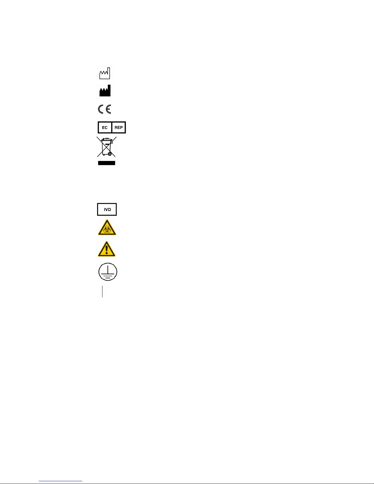
Labels Used On the System
The labels attached to the panels of the system use symbols to clarify the meaning of the
text. The chart below explains the symbols on the labels.
Serial Number
Page 8
Foreward 2
Date of Manufacture
Manufacturer
CE marking. The device is fully in conformity with the
Council Directive Concerning In Vitro Diagnostic
Medical Devices 98/79/EC.
Authorized Representative in the European
Community
The following definition of the WEEE label applies to
EU member states only: The use of this symbol
indicates that this product should not be treated as
household waste. By ensuring that this product is
disposed of correctly, you will help prevent bringing
potential negative consequences to the environment
and human health. For more detailed information with
regard to returning and recycling this product, please
consult the distributor from whom you purchased the
product.
In Vitro diagnostic equipment
Biohazard warning: risk of potentially biohazardous
infection
Warning: Risk of personal injury or equipment damage
Protective ground terminal
ON (Power)
Graphics
All graphics, including screens and printout, are for illustration purposes only and must
not be used for any other purpose.
EC Representative
Name: Shanghai International Holding Corp. GmbH (Europe)
Address: Eiffestraβe 80, 20537 Hamburg Germany
Phone: 0049-40-2513175
Fax: 0049-40-255726
Page 9
Foreward 3
Safety Precautions
Observe theses safety precautions when using the system. Ignoring any of the
precautions may lead to personal injury or equipment damage.
WARNING
If the instrument is used in a manner not specified by our company, the
protection provided by the system may be impaired.
Preventing Electric Shock
Please observe the following instructions to prevent electric shock.
WARNING
When the instrument is turned on, users must not open the cover.
Spillage of reagent or sample on the analyzer may cause equipment
failure and even electric shock. Do not place sample and reagent on
the analyzer. In case of spillage, switch off the power immediately,
remove the spillage and contact our company customer service
department or your local distributor.
This instrument is supplied with a slow-blow fuse (250V, 3.15A), which
must not be replaced by the user.
Power supply: 100-240V~, 50/60Hz.
The instrument is supplied with a three-wire power cord and should be
properly grounded during application.
Preventing Personal Injury Caused by Moving Parts
Please observe the following instructions to prevent personal injury caused by moving
parts.
WARNING
Do not put your finger or hand into any open part when the system is in
operation.
Page 10
Foreward 4
Preventing Personal Injury Caused by Photometer Lamp
Please observe the following instructions to prevent personal injury caused by
photometer lamp.
WARNING
Light sent by the photometer lamp may hurt your eyes. Do not stare into
the lamp when the system is in operation.
If you want to replace the photometer lamp, first switch off the Main
Power and then wait at least 15 minutes for the lamp to cool down
before touching it. Do not touch the lamp before it cools down, or you
may get burned.
Preventing Infection
Please observe the following instructions to protect against the biohazardous infection.
BIOHAZARD
Inappropriately handling samples may lead to biohazardous infection. Do
not touch the sample, mixture or waste with your hands. Wear gloves and
lab coat and, if necessary, goggles.
In case your skin contacts the sample, follow standard laboratory safety
procedures and consult a doctor.
Handling Reagents and Wash Solution
WARNING
Reagents and enhanced wash solution may hurt human skins. Exercise
caution when using the reagents and enhanced wash solution. In case
your skin or clothes contact them, wash them off with clean water. In
case the reagents or wash solution spill into your eyes, rinse them with
much water and consult an oculist.
Page 11
Foreward 5
Treating Waste Liquids
Please observe the following instructions to prevent environmental pollution and personal
injury caused by waste.
BIOHAZARD
Some substances in reagent, control, enhanced wash solution and
waste are subject to regulations of contamination and disposal. Dispose
of them in accordance with your local or national guidelines for
biohazard waste disposal and consult the manufacturer or distributor of
the reagents for details.
Wear gloves and lab coat and, if necessary, goggles.
Treating Waste Analyzer
Please observe the following instructions to dispose of the waste analyzer.
WARNING
Materials of the analyzer are subject to contamination regulations. Dispose
of the waste analyzer in accordance with your local or national guidelines
for waste disposal.
Preventing Fire or Explosion
Please observe the following instructions to prevent fire and explosion.
WARNING
Ethanol is flammable substance. Please exercise caution while using the
ethanol.
Page 12

Foreward 6
Precautions on Use
To use the system safely and efficiently, please pay much attention to the following
operation notes.
Intended Use
WARNING
The system is an analyzer designed for in vitro quantitative
determination of clinical chemistries in serum, plasma, urine and CSF
samples. Please consult Mindray first if you want to use the system for
other purposes.
To draw a clinical conclusion, please also refer to the patient’s clinical
symptoms and other test results.
Operator
WARNING
The system is to be operated only by clinical professionals, doctors or
laboratory experimenters trained by our company or our authorized
distributors.
Environment
CAUTION
Please install and operate the system in an environment specified by this
manual. Installing and operating the system in other environment may lead
to unreliable results and even equipment damage.
To relocate the system, please contact our customer service department or
your local distributor.
Page 13
Foreward
7
Preventing Interference by Electromagnetic Noise
CAUTION
Electromagnetic noise may interfere with operations of the system. Do
not install devices generating excessive electromagnetic noise around
the system. The electromagnetic environment should be evaluated
prior to operation of the device. Do not use such devices as mobile
phones or radio transmitters in the room housing the system. Do not
use other CRT displays around the system. The electromagnetic noise
might lead to system failures.
Do not use other medical instruments around the system that may
generate electromagnetic noise to interfere with their operations.
NOTE
It is the manufacturer's responsibility to provide equipment
electromagnetic compatibility information to the customer or user.
NOTE
It is the user's responsibility to ensure that a compatible
electromagnetic environment for the equipment can be maintained in
order that the device will perform as intended.
Operating the System
CAUTION
Operate the system strictly as instructed by this manual. Inappropriate use
of the system may lead to unreliable test results or even equipment
damage or personal injury.
Before using the system for the first time, run the calibration program and
QC program to make sure the system is in normal status.
Be sure to run the QC program every time you use the system, otherwise
the result may be unreliable.
Do not touch the screen with wet hands or hands contaminated by
chemicals.
Do not place the Power to ON again within 10 seconds since placing it to
OFF;
Page 14
Foreward 8
Maintaining the System
CAUTION
Maintain the system strictly as instructed by this manual. Inappropriate
maintenance may lead to unreliable results, or even equipment damage
and personal injury.
To wipe off dust from the system surface, use a soft, clean and wet (not too
wet) cloth, soaked with mild soap solution if necessary, to clean the
surface. Do not use such organic solvents as ethanol for cleaning. After
cleaning, wipe the surface with dry cloth.
Switch off all the powers and unplug the power cord before cleaning. Take
necessary measures to prevent water ingression into the system,
otherwise it may lead to equipment damage or personal injury.
Replacement of such major parts as lamp assembly must be followed by a
calibration.
Check the pump tubing for leakage as needed and replace the tubing in
time. Otherwise, the normal aspiration of the system might be affected. It is
recommended that the inner system tubing should be replaced every 24
months to avoid possible blockage or invalidation brought about by aging.
Setting up the System
CAUTION
To define such parameters as calculation method and wavelength, follow
the instructions in this manual and the package insert of the reagents.
Page 15

Foreward 9
Samples
CAUTION
Use samples that are completely free of insoluble substances like fibrin, or
suspended matter; otherwise the probe may be blocked.
Medicines, anticoagulants or preservative in the samples may lead to
unreliable results.
Hemolysis, icterus or lipemia in the samples may lead to unreliable test
results, so a sample blank is recommended.
Store the samples properly. Improper storage may change the
compositions of the samples and lead to unreliable results.
Sample volatilization may lead to unreliable results. Do not leave the
sample open for a long period.
Some samples may not be analyzed on the system based on parameters
the reagents claim capable of testing. Consult the reagent manufacturer or
distributor for details.
Certain samples need to be processed before being analyzed by the
system. Consult the reagent manufacturer or distributor for details.
Reagents, Calibrators and Controls
CAUTION
Use appropriate reagents, calibrators and controls on the system.
Select appropriate reagents according to performance characteristic of the
system. Consult the reagent suppliers, our company or our authorized
distributor for details, if you are not sure about your reagent choice.
Store and use reagents, calibrators and controls strictly as instructed by
the suppliers. Otherwise, you may not obtain reliable results or best
performance of the system.
Improper storage of reagents, calibrators and controls may lead to
unreliable results and bad performance of the system even in validity
period.
Perform a calibration after changing reagents. Otherwise, you may not
obtain reliable results.
Contamination caused by carryover among reagents may lead to
unreliable test results. Consult the reagent manufacturer or distributor for
details.
Page 16
Foreward 10
External Equipment
WARNING
External equipment connected to the analogue and digital interfaces
must be complied with the relevant Safety and EMC standards (e.g., IEC
60950 Safety of Information Technology Equipment Standard and CISPR
22 EMC of Information Technology Equipment Standard (CLASS B)).
Any person, who connects additional equipment to the signal input or
output ports and configures an IVD system, is responsible for ensuring
that the system work normally and complies with the safety and EMC
requirements. If you have any problem, consult the technical services
department of your local representative.
Communication interface
CAUTION
The system is equipped with two USB ports which can be used in
connecting the keyboard, mouse, printer and other external
equipments or in system upgrading. RS232 is used in connecting the
PC with the analyzer to transfer data.
These three ports should not be used to operate the system for usage
other than those mentioned above. Otherwise, system might be
damaged.
Page 17

Contents
I
Contents
Contents.................................................................................................................. I
1
System Specifications .............................................................................. 1-1
1.1 System specifications............................................................................................. 1-1
1.2 Parameters ............................................................................................................ 1-1
1.3 Instrument Configuration ........................................................................................ 1-2
1.4 Overview................................................................................................................ 1-2
2
System Installation.................................................................................... 2-1
2.1 Basic...................................................................................................................... 2-1
2.2 Installation Procedures........................................................................................... 2-2
3
System Description................................................................................... 3-1
3.1 Operating Procedures ............................................................................................ 3-1
3.2 Component Structure and Functions....................................................................... 3-2
3.2.1 Photometer Assembly................................................................................ 3-2
3.2.2 Lamp assembly ......................................................................................... 3-3
3.2.3 Lamp Base Assembly ................................................................................ 3-5
3.2.4 Flow Cell Base Assembly........................................................................... 3-9
3.2.5 Base Plate Assembly............................................................................... 3-12
3.2.6 Enclosure Assembly ................................................................................ 3-13
4
Hardware....................................................................................................4-1
4.1 Overview................................................................................................................ 4-1
4.2 Safety Precautions................................................................................................. 4-1
4.3 Introduction of the Modules .................................................................................... 4-1
4.4 CPU Board............................................................................................................. 4-2
4.4.1 LED Indicator............................................................................................. 4-2
4.4.2 Memory Module......................................................................................... 4-2
4.4.3 Clock Module............................................................................................. 4-3
4.4.4 Interface Module........................................................................................ 4-3
4.5 CPU Extension Board ............................................................................................ 4-3
4.5.1 Overview ................................................................................................... 4-3
4.5.2 LED Indicator............................................................................................. 4-4
4.5.3 USB Functions........................................................................................... 4-4
4.5.4 LCD&Touchscreen Driver Control .............................................................. 4-5
4.5.5 Serial Port Communication ........................................................................ 4-5
4.5.6 Driver of the Step Motor............................................................................. 4-6
4.5.7 Driver of the Peristaltic Pump..................................................................... 4-6
4.5.8 Driver of the Refrigeration Plate ................................................................. 4-6
4.5.9 Detection of the Input Signal ...................................................................... 4-7
4.5.10 Analogue Board Control........................................................................... 4-7
Page 18

Contents II
4.6 Analogue Board ..................................................................................................... 4-7
4.7 LCD&Touchscreen Board....................................................................................... 4-8
4.8 Power board .......................................................................................................... 4-9
4.8.1 Overview ................................................................................................... 4-9
4.8.2 The Basic Feature of the Power Module..................................................... 4-9
4.9 LCD Background Adjustment ............................................................................... 4-10
4.10 Connection of the Hardware System..................................................................4-11
4.10.1 Definition of the CPU Board + CPU Extension Board Interface................4-11
4.10.2 Analogue Board Interface ...................................................................... 4-12
4.10.3 Power Board Interface ........................................................................... 4-12
4.10.4 LCD&Touchscreen Board Interface ........................................................ 4-13
5
Service and Maintenance..........................................................................5-1
5.1 Maintenance .......................................................................................................... 5-2
5.1.1 Daily Maintenance ..................................................................................... 5-2
5.1.2 Weekly Maintenance.................................................................................. 5-2
5.1.3 Irregular Maintenance................................................................................ 5-2
5.2 Software Upgrading................................................................................................ 5-3
5.2.1 Software Structure..................................................................................... 5-3
5.2.2 Software List.............................................................................................. 5-4
5.2.3 Upgrading Procedures for Software on CPU Board.................................... 5-5
5.2.4 Upgrading Procedures for Software on CPU Extension Board.................... 5-7
5.3 Maitenance .......................................................................................................... 5-12
5.3.1 Replacing the tubing................................................................................ 5-12
5.3.2 Replacing Aspiration Tubing..................................................................... 5-16
5.3.3 Replacing Lamp....................................................................................... 5-17
5.3.4 Replacing CPU Board.............................................................................. 5-19
6
Troubleshooting ........................................................................................6-1
6.1 Alarm Message Classification................................................................................. 6-1
6.2 Levels.................................................................................................................... 6-1
6.2.1 Errors to Warn User (0).............................................................................. 6-2
6.2.2 Errors to Invalidate Tests(1) ....................................................................... 6-2
6.2.3 Errors to Forbid Test(2).............................................................................. 6-2
6.3 Error Display.......................................................................................................... 6-2
6.3.1 Dialog Box................................................................................................. 6-2
6.3.2 Sound........................................................................................................ 6-2
6.4 Details.................................................................................................................... 6-3
Page 19

1 Systemystem Specifications 1-1
1 System Specifications
1.1 System specifications
Dimension: ≤420mm ×350mm ×158mm(L×W×H)
Weight: ≤7Kg
Power supply: 100-240V~, 50/60Hz;
Power consumption: maximum 140VA;
Operating methods: touchscreen, USB key board and mouse.
1.2 Parameters
Reaction type: Endpoint, Kinetics, Fixed-time, Absorbance;
Analyzing methods: single/double- wavelength;
Clinical chemistries, immunoassays, TDM (Therapeutic Drug Monitoring)
Aspiration volume: 200μl-9000μl ;
Temperature: room temperature, 25℃, 30℃, 37℃;
Capable of storing and outputting various data and tables/graphs, and
calculating among different tests
Storage capacity: capable of storing more than 3000 test results.
Page 20

1 Systemystem Specifications 1-2
1.3 Instrument Configuration
Wavelengths: 6 wavelengths (available): 340nm, 405nm, 510nm, 546nm,
578nm and 630nm.2 wavelengths (optional): 450nm and 670nm.
Reaction container: flow cell or cuvette.
Printing: thermal recorder.
1.4 Overview
Colorimetric system: The colorimetric analysis is realized through the
combination of optical collimating, mono-color filter, mechanical parts and
software, hardware module.
Aspiration system: it is used to aspirate the matter to be tested or to wash the
tubing system (only for flow cell system).
Software/hardware system: it is used to set tests, enter operating instructions,
control the data collection, calculate and save the results.
Page 21

2 System Installation 2-1
2 System Installation
2.1 Basic
Make sure the installation site of the hospital meet the system installation
requirements on space, power supply and environment. Please refer to the
operator’s manual for details.
If data management software or test and maintaenance software is used on PC,
please make sure the configuration of the PC meet the system requirement.
1 PC requirement for test and maintenance software:
CPU: Celeron 1.7 or above;
Memory: 256M or above;
Resolution of the screen: 1024*768;
Operating system: windows 2000(professional/server SP4), windows
xp(home/professional SP1 or above)
Communication interface: RS-232C
2 PC requirement for data management software:
CPU: Pentinum II or above;
Memory: at least 1G for Vista operating system; at least 512 M for other
operating system.
Resolution of the screen: 1024*768 or above;
Operating system: Windows XP/Vista/Windows 2000
Page 22

2 System Installation 2-2
Databse: SqlServer 2005 Express
Network communication: 10/100M 10/100M
Communication interface: RS-232C
Hard disk ( the disk on which the software is installed): 10G
Printer (connected with PC)
2.2 Installation Procedures
1 When you receive the system, carefully inspect the package. After opening
the package, check the delivered goods against the packing list.
2 Move the instrument to the installation site and remove all the package and
protective materials.
3 Connect the instrument to waste container.
4 Connect the power cable and power on the analyzer. After self-check and
tubing wash is completed, the main screen is displayed.
5 After the system is stable, request one or two routine tests and run. Assess
the test results. Please refer to the operator’s manual for details.
6 Follow the normal procedure to shutdown the analyzer.
7 Training:
Can the customer complete daily tests?
Yes □ No □
Is the customer familiar with the daily, weekly and monthly maintenance and
relevant maintenance methods? Yes □ No □
Is the customer familiar with cleaning and washing the system?
Yes □ No □
Is the customer familiar with troubleshooting the common failures?
Yes □ No □
Is the customer familiar with replacing the peristaltic pump tubing and
calibrating the flow volume? Yes □ No □
Is the customer familiar with replacing the aspiration tubing? Is the customer
familiar with replacing the lamp? Yes □ No □
Page 23
3 System Description 3-1
3
System Description
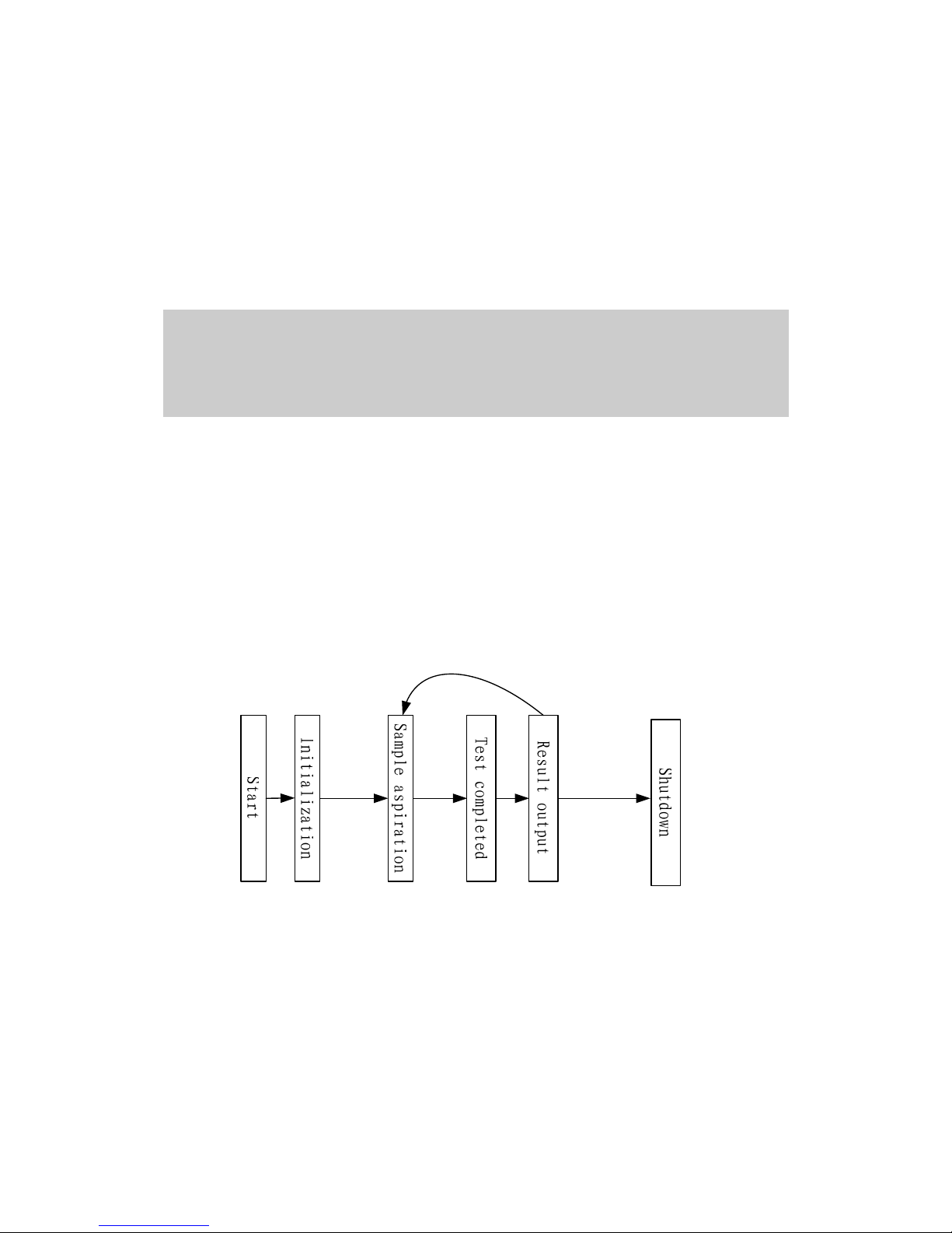
3.1 Operating Procedures
The typical operating procedure of BA-88A is shown as follows:
Figure 3-1 Operating procedure
Lamp
stabilization
Reaction
All the
tests
finished
Temperature
stabilization
Other
tests
Procedures:
1 Empty the waste. Connect the waste tubing to the waste container. Prepare
the samples, reagents and distilled water;
2 Connect power cable correctly. Power on the analyzer. The instrument will
under go the initialization processes, including; system startup, hardware
self-check, parameters download, dark current testing. After initialization,
wait until the temperature and the light source are stable. The whole
process lasts for about 15 minutes;
3 After the system is stable, set the parameters of the tests, such as
wavelength, temperature, methods and etc. Start the test.
Page 24
3 System Description 3-2
4 After the test is completed, run other tests if necessary. Washing should be
inserted between two tests to minimize the carryover, when the
concentrations of the two tests are too different or the two tests are different.
5 After all the tests are completed, shutdown the analyzer. Cut off the
instrument power after washing is completed.
3.2 Component Structure and Functions
3.2.1 Photometer Assembly
3.2.1.1 Introduction
Photometer assembly is the core of BA-88A, integrating optical system, temperature
control system and photoelectrical collection system. The photometer assembly is the
key for reliability of the system. Photometer assembly includes lamp assembly, lamp
base assembly, flow cell assembly and other components, which are used to position
and install the optical components, thermal components and analogue board.
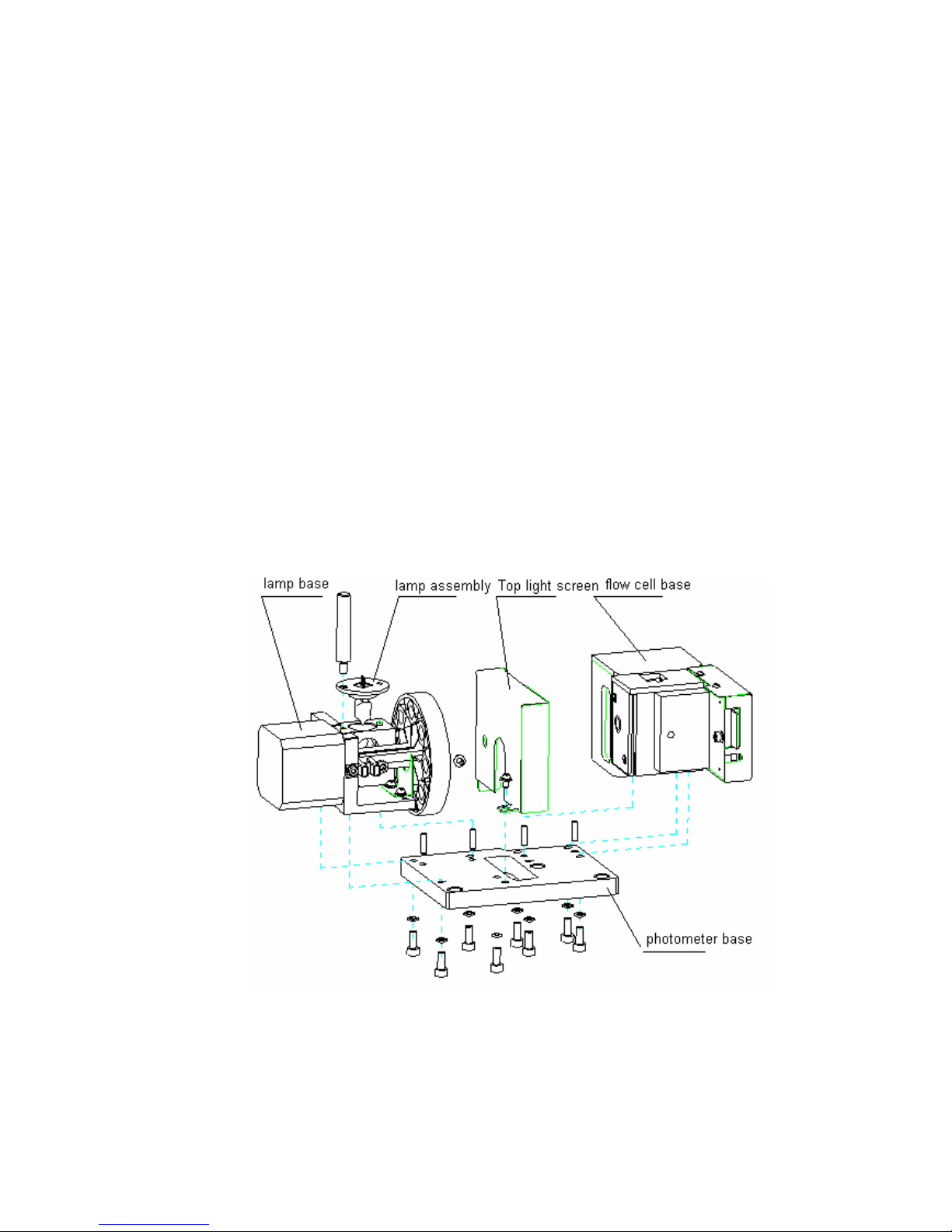
3.2.1.2 Components and Structure
The basic structure of the photometer assembly is shown as figure 3-2.
Figure 3-2 Photometer assembly structure
3.2.1.3 Assembly and Disassembly of the Photometer
Assembly
Photometer assembly is fixed on the instrument base by 3 M4 socket head screws.
Page 25

3 System Description 3-3
Maintenance of the system, except for replacing the assemblies or components other
than lamp assemblies will involve the assembly and disassembly of the photometer
assembly as a whole. Please pay attention to the following:
1 When disassembling the instrument, do not drag the cable with excessive force.
If necessary, you can disconnect the connection of some cables in advance. Do
not make any cable pressed, especially the cable under the photometer base.
2 When disassembling the instrument, do not press the air duct or conduct any
operation that might distort the air duct, otherwise the refrigeration plate might be
damaged.
3.2.2 Lamp assembly
3.2.2.1 Introduction
The lamp assembly is the light source of the instrument, providing energy source for
the detection system. Among the components of the lamp assembly, the lamp should
be replaced regularly, so when we design the system, we take the manual
replacement into consideration, taking the assembly as a whole connected with the
lamp base, fixing it with a long hand screw to facilitate manual disassembly.
3.2.2.2 Components and Structure
The basic structure of the lamp assembly is shown as figure 3-3.
Figure 3-3 Lamp assembly structure
3.2.2.3 Assembly and Disassembly of the Lamp Assembly
Lamp assembly is connected with lamp base assembly through lamp fixing screw
and aφ3 pin. (figure 3-2).
Page 26

3 System Description 3-4
The replacement of lamp assembly is shown in the following picture.
Figure 3-4 Procedure for lamp replacement
Components relevant to lamp replacement are shown in the following figure. For
more details please refer to 5.3.3.
Page 27

3 System Description 3-
5
Figure 3-5 Lamp assembly structure
WARNING
If you want to replace the lamp, first switch off the power and then wait at
least 15 minutes for the lamp to cool down before touching it. Do not touch
the lamp before it cools down, or you may get burned.
NOTE
When replacing the lamp assembly, do not touch the surface of the bulb to
avoid contamination.
icult to
3.2.3 Lamp Base Assembly
3.2.3.1 Introduction
The lamp base assembly supports the installation and positioning of the lamp
assembly and in the meantime supports the installation and positioning for filter wheel
and driver motor.Integration structure design will increase the positioning accuracy of
the optical elements.
Page 28

3 System Description 3-6
3.2.3.2 Components and Structure
The assembly is composed of lamp base, filter wheel, step motor and etc. The
structure is shown as the following figure.
Figure 3-6 Lamp base assembly structure
3.2.3.3 Assembly and Disassembly of the Lamp Base Assembly
Lamp base assembly is fixed on the instrument base by 4 M4 socket head screws
and positioned by 2φ3 pins. When the assembly is dismounted as a whole, you can
disassemble the components, but you have to pay attention to the following
problems:
1 If fixture is not used when you assemble or disassemble the filter, extra care
should be taken lest the filter is scratched by the screw driver. Please follow the
correct order to install the filter. The order is shown in the following table.
No. 1 2 3 4 5 6 7 8
Wavelength
nm
340 405 546 670 450 510 578 630
450 nm and 670 nm are optional wavelengths. When these two wavelengths are
not configured, relevant position is shielded by stop plate; when relevant filters are
installed, the arrow on the circle should point outward of the hole.
2 When assembling or disassembling the home position sensor, place the surface
with text onward (refer to the base plate).
3 When assembling or disassembling the lens, make sure the spherical surface
face the outside. Press it until secure with clamping ring. Make sure that the
outer surface of the clamping ring is at the same level with or higher than the
Page 29

3 System Description 3-
7
surface of the lamp base. If obvious blow-up is found, skewed installation of the
lens might be the cause and the readjustment might be needed.
4 When disassembling, if it is not necessary to replace the motor, filter wheel or
sensor stop plate, we recommend you to keep the connection between the motor
and the filter wheel, thus the installing procedure would be simplified; otherwise,
the relative position between the filter wheel and the motor positioning surface
might change. Fixture BA89-J01 should be used to position. If there is no fixture
on the spot, ensure distance between the position surface of the control motor
and the filter wheel end face is 59.6±0.5mm. Please refer to the following figure.
Figure 3-7 Filter wheel positioning
5 During assembly and disassembly, ensure that optical elements like filter, lens
and bulb are properly protected. When installation is completed, use balloon to
blow away the dust or other impurities from the surface of the optical elements.
3.2.3.4 Adjust the Filter Wheel Home Position
If any of the following components: filter wheel, home position sensor, motor is
dismounted or conduct any operation that might lead to the dismounting of these
components, the home position of the filter wheel might be modified, so the test result
might be inaccurate. Thus, dismounting of these elements should be followed with
the adjustment of home position of the filter wheel. During adjustment, PC, serial
cable and test&maintenance software are used. The procedure for adjusting is shown
as follows:
1 After the instrument is reassembled, power on the analyzer.
2 Click Maintenance on the main screen of the instrument. Select Maintenance
tab. Click Advanced and enter the password “analyzer” to enter the advanced
adjustment interface.
3 Click H pos..
4 When the system is in Standby (if Lamp stabilizing is displayed, tests can only
be started when lamp is stabilized), Put the aspiration tubing into a tube filled
with about 2 ml of distilled water. Click Asp.. When the aspiration is completed,
click Start to calculate the deviation.
Page 30

3 System Description 3-8
5 After completing the serial port setting, click Enable Para. Modification on the
screen. Select the tab Photoele. And Fluid and then select Filter wheel home
position to enter the following screen.
Figure 3-8 Adjusting home position of the filter wheel
6 It will take 3 minutes to complete the test. When the test is completed, the
deviation of the filter wheel will be displayed in Deviation. The deviated steps
should be within 0-63, otherwise, the position of the home position sensor should
be adjusted before testing.
Tips: when the value of the deviated steps is higher than 63, move the sensor
downward; when the value is lower than 0, move it upward. When the above
requirements are met, click Save.
Figure 3-9 View parameters
7 When operations above are completed, click Return to go back to the main
screen. The analyzer will restart automatically. When analyzer is stable (after
about 15-20 minutes), click Maintenance-Maintenance on the analyzer to enter
the maintenance screen. Select Gain adjust on the screen to adjust the
photoelectric gain of the system. When adjustment is completed, wait at least 15
minute to start testing. Please refer to the operator’s manual for details on
photoelectric adjustment.
Page 31

3 System Description 3-9
NOTE
Wear clean cotton gloves, when replacing the filter or lens. If contaminant is
found on the surface of the filter or lens, clean it with ethanol.
NOTE
The assembly or disassembly of the filter wheel, motor or home position
sensor should be followed with home position deviation adjustment.
Otherwise, the test result might not be reliable.
The home position deviation adjustment of the filter wheel should be followed
with the adjustment of photoelectric gain. Otherwise, the test result might not
be reliable.
3.2.4 Flow Cell Base Assembly
3.2.4.1 Introduction
The flow cell, temperature control elements, analogue board and etc are installed and
positioned by the flow cell base assembly. Two modes—flow cell and cuvette are
available on the system. Manual replacement is supported. The temperature control
system is composed of semi-conductor refrigeration plate, air duct, temperature
sensor and insulation material, providing 37℃, 30℃ and 25℃ which are needed on
the system. Analogue board collects the data of absorbance and temperature.
3.2.4.2 Components and Structure
The structure of the flow cell assembly is shown in the following figure.
Page 32

3 System Description 3-10
Figure 3-10 Flow cell assembly structure
3.2.4.3 Assembly and Disassembly of the Flow Cell Base Assembly
Flow cell assembly is fixed on the instrument base by 4 M4 socket head screws and
positioned by 2φ3 pins. When maintaining the components on the side of analogue
board and air duct, it is not necessary to dismount the flow cell base assembly and
maintenance can be done on the dismounted photometer assembly. When
dismounting the components other than the position mentioned above, dismounting
of the whole assembly is needed. When dismounting the assembly and relevant
components, please pay attention to the following:
1
When replacing the refrigeration plate, we recommend you to replace it after
dismounting the photometer assembly. The order is: 1. dismount the photometer
assembly as a whole; 2. dismount the flow cell air duct; 3. dismount the
refrigeration plate; 4. replace the refrigeration plate. Reverse the above
procedures to install.
2
When installing the refrigeration plate, please pay attention to the installing
direction. The cable should project at the side of the analogue board and the red
cable should be lower;
3
The semi-conduct refrigeration plate should be installed between the air duct
and the flow cell base. Before installing, apply heat conducting gel to both sides
of the refrigeration plate (the thickness is about 0.05-0.1mm, the gel should be
evenly applied and no granule or nodular matter is allowed; the gel should not be
too watery). Correctly stick the plate inside the groove of the flow cell assembly
(follow step 2).Stick the air duct to the other side of the plate and tighten it with
spring and spring lightener. The two longer spring lightener should be inside the
hole on the upper side of the air duct and insulation is needed. Use straight slot
head screw driver to tighten the screws.
Page 33

3 System Description 3-11
4
When replacing the optical components, take care to protect the components.
Do not touch the surface of the optical elements with bare hand.
5
Wear antistatic gloves to dismount and mount the analogue board;
6
Do not drag the cable with excessive force. If necessary, you can disconnect the
connection of some cables in advance.
7
When replacing the temperature sensor, please take care to dismount the
insulation cotton, otherwise damage might occur; when reinstalling, use double
glue to stick the insulation back.
3.2.4.4 Replacement of the Temperature Measurement Assembly
The analogue board and the temperature sensor are components for measuring the
temperature on flow cell base assembly, so they should be replaced together.
Replacement of the two should be followed with parameter configuration. The
method is indicated as follows:
1 When the instrument is reinstalled, power on the system.
2 Click Maintenance on the main screen of the instrument. Select Maintenance
tab. Click Advanced and enter the password “analyzer” to enter the advanced
adjustment interface.
3 Select Temp. to enter the following screen. Select Cell. Enter the A, B, C
parameters on the flow cell accessory into their respective positions, making sure
that they are in accordance with those on the accessory. Click Save.
Figure 3-11 Parameter configuration
4 Select Cuvette. Repeat the operation in step 3 to configure the A, B and C
parameters.
5 After above operations are completed, click Return. Click View para. and make
sure the inquired A, B and C parameters are in accordance with those on the
accessory. Click Return.
6 Exit the Maitenance screen and the system will restart. Follow the instruction to
complete the configuration of the temperature.
Page 34

3 System Description 3-12
NOTE
If either of the temperature sensor or analogue board is damaged, both
of the two should be replaced by one assembly at the same time. And
the replacement should be followed with temperature paremter
configuration.
During configuration, modifying parameters other than temperature
parameters should not be allowed. Otherwise, the test result might be
affected.
3.2.5 Base Plate Assembly
3.2.5.1 Introduction
The base plate assembly supports the system, providing fixing and support for
photometer assembly, hardware board, interface and other components.
3.2.5.2 Components and Structure
The basic structure of the base plate assembly is shown as figure 3-12.
Figure 3-12 Base plate assembly structure
3.2.5.3 Assembly and Disassembly of the Base Plate Assembly
The base plate assembly is a strutting piece of sheet metal, providing fixing and
support for photometer assembly, hardware board, interface and other components.
Pay attention to the following while assembling and disassembling it.
1 When assembling and disassembling the photometer assembly, do not drag the
cable with excessive force, especially the cable of the semiconductor
Page 35

3 System Description 3-13
refrigeration plate, lamp cable and the connection cable of analogue board. If
necessary, you can disconnect the connection of some cables in advance.
2 Replacement of the peristaltic pump should be followed with flow volume
calibration (this is not for system configured with cuvette). Please refer to the
operator’s manual for details.
3 Wear antistatic gloves to replace the hardware board.
WARNING
When the enclosure is opened, do not touch the boards, sockets, switch
and etc, when the system is powered on, otherwise, electric shock might
occur.
3.2.6 Enclosure Assembly
3.2.6.1 Introduction
The enclosure assembly supports and fixes the touchscreen, recorder, aspirate
button, other input and output components and etc. Optical window cover and lamp
replacement window cover are designed to facilitate the replacement of flow cell,
cuvette and lamp.
3.2.6.2 Components and Structure
The basic structure of the enclosure assembly is shown as figure 3-13.
Figure 3-13 Enclosure assembly structure
Page 36

3 System Description 3-14
3.2.6.3 Assembly and Disassembly of the Enclosure Assembly
The enclosure assembly is fixed by 11 screws which are connected to the base plate.
Of the 11 screws, 3 are located at the back of the system and the remaining which
can be dismounted directly are located under the enclosure. When assembling and
disassembling the enclosure, please pay attention to the following:
1 If the system is configured with flow cell, before opening the enclosure, move the
flow cell out of the installing location and place it in the hole for holding flow cell
temporarily. Otherwise, the tubing connection will be dragged off.
2 When opening the enclosure, do not drag the cable with excessive force.
3 Place the enclosure in a stable location to make it stand vertically. If the
enclosure falls down, some cables, especially the touchscreen board cable,
aspirate button cable, might be dragged.
When installing the LCD/touchscreen module, pay attention to the following as shown
in figure 3-14.
1 When installing LCD cable, the blue face (untouchable face) of the FPC should
face outward;
2 When installing the LCD data cable of LCD&touchscreen board, the metal face
of the FPC cable (touchable face) should face outward;
3 When installing the touchscreen data cable of LCD&touchscreen board, the
metal face of the FPC cable (touchable face) should face outward;
4 When installing the supporting plate of the touchscreen, tighten the four screws
gradually one by one to avoid uneven force on the screen and excessive
tightening force on the screw which will result in false reaction of the
touchscreen.
Enclosure Touchscreen
Aspirate button
Recorder
Touch screen
supporting board
Aspirate button movement
switch
Cover of
lamp
replacement
window
Enclosure
fixing screw
hole
Hole for holding
flow cell t
temporarily
Page 37

3 System Description 3-15
Figure 3-14 LCD/touchscreen cable
The blue face
should face
outward
The metal face
should face
outward
The metal face
should face
outward
Touchscreen
FPC cable
Page 38

Page 39

4 Hardware 4-1
4
Hardware
4.1 Overview
This chapter describes the function of circuit boards in the BA-88A.
4.2 Safety Precautions
WARNING
Don’t touch the circuit boards by hand or others, when the analyzer is
working.
If you are about to detach the circuit boards, you should cut off the
power of the analyzer.
Please wear the glove to protect the circuit boards from ESD or release
the charge first when you detach the circuit boards.
4.3 Introduction of the Modules
The hardware system of the BA-88A is divided into the following modules or boards:
1 Main unit: CPU board, CPU extension board;
2 Data collection board: analogue board;
3 Human-machine communication module: LCD&touchscreen board;
4 The power module: Power board
Page 40

4 Hardware 4-2
Figure 4-1 The structure of hardware system
4.4 CPU Board
CPU board which is the minimum structure system of CPU system uses 32 digit chip
microcomputer as its core. CPU board and CPU extension board make up of the
main module.
The CPU communicates with the CPU extension board via CPU external interface in
multiple-buses communication mode.
Figure 4-2 Structure of the CPU board
4.4.1 LED Indicator
D3: +3.3V power indicator
4.4.2 Memory Module
Flash which communicates with CPU via local bus, is used to store the CPU program,
system parameters and test results.
SDRAM which is configured on CPU board, is used to run the software.
Page 41

4 Hardware 4-3
4.4.3 Clock Module
The real time clock circuit which is composed of real time clock and battery, is to
realize the function of real time clock on CPU board.
4.4.4 Interface Module
CPU communicates with the CPU extension board via various bus interfaces on CPU
board. The sockets on CPU board are, J2, J3 and J10; the sockets on CPU extension
board are J5, J6 and J4.
4.5 CPU Extension Board
4.5.1 Overview
The CPU extension board realizes some functions of the CPU external interfaces.
Such as:
USB functions;
LCD driver control;
Touchscreen control;
Recorder serial port communication;
Hummer control;
PC serial port communication.
In the meantime, the CPU extension board receives the command and completes the
following tasks:
Control and driving of the moving parts;
Checking of the input signal;
Data collection;
Data transfer of the CPU board.
The function graph is shown in the following figure:
Page 42

4 Hardware 4-4
Figure 4-2 Structure of the CPU extension board
4.5.2 LED Indicator
D3: ++12V power indicator
D6: ++24V power indicator
D7: ++5.0V power indicator
D17: +3.3V power indicator
4.5.3 USB Functions
USB controller is configured on the CPU extension board which communicates with
the CPU via bus and realizes the USB communication function via USB interface.
USB power control and ESD protector is added between the USB controller and the
USB interface.
Page 43

4 Hardware 4-
5
Figure 4-4 Structure of USB functions
4.5.4 LCD&Touchscreen Driver Control
CPU realizes the functions of LCD drive control, reading touch screen data,
transforming data transfer protocol.
Figure 4-5 Graph of LCD/touchscreen drive control
4.5.5 Serial Port Communication
The COM0 of CPU board uses RS232 level translator to translate the level, realizing
the serial port communication with PC. The communication between COM3 and
recorder is realized through the level translation between LVTTL and TTL.
Figure 4-6 Graph of serial port communication
Page 44

4 Hardware 4-
6
4.5.6 Driver of the Step Motor
Figure 4-7 Graph of the step motor driver
The control module of the CPU extension board (including: MCU and FPGA) outputs
motor control signal, which can control the step motor of the filter wheel via step
motor driver circuit.
4.5.7 Driver of the Peristaltic Pump
Figure 4-8 Graph of the peristaltic pump driver
The control module of the CPU extension board (including: MCU and FPGA) outputs
peristaltic pump control signal, which can control the motor of peristaltic pump via
power driver circuit.
4.5.8 Driver of the Refrigeration Plate
Figure 4-9 Graph of the refrigeration plate driver
The control module of the CPU extension board (including: MCU and FPGA) outputs
motor control signal, which can control the refrigeration plate via power driver circuit.
Page 45

4 Hardware 4-
7
4.5.9 Detection of the Input Signal
Figure 4-10 Graph of input signal detection
The system should detect the signal from filter position sensor, aspirate button,
cuvette temp. controlling fan blocking. Before detected by control module, all input
signals should go through the level translation circuit.
4.5.10 Analogue Board Control
Figure 4-11 Graph of analogue board controlling
Three signals are controlled by analogue board: digital potentiometer control signal
(DCPx), channel selection signal (CH), AD collection and control signal (AD_Ox and
AD_lx). All control signals are generated by control module. The signals between the
control module end and analogue board should go through level translation (TTL to
LVTTL).
4.6 Analogue Board
The analogue board realizes the functions of photoelectric signal, temperature
sensor signal modulation and amplification, AD collection.
The photodiode transforms the light signal which has passed through the flow
cell (or cuvette) into voltage signal. The voltage signal will be filtered,
amplified inversely, and finally output at the outputting end of the AD
converter through selectable switch.
Page 46

4 Hardware 4-
8
The temperature sensor outputs the voltage signal to the analogue board,
where it will go through amplification and modulation. Finally, it will be output
at the inputting end of the AD converter through selectable switch.
The AD converter receives control signal from the CPU extension board and
samples the processed photoelectric/temperature signal and sends the AD
value to CPU extension board for processing.
The power of the analogue board is provided by power board.
Figure 4-12 Structure of the analogue board
D12: +12V power indicator
D13: -12V power indicator
D14: +5.0V power indicator
4.7 LCD&Touchscreen Board
LCD&touchscreen board realizes the functions of LCD and touchscreen driver and
signal transmission.
LCD&touchscreen board receives the LCD display control/data signal which
is exported from CPU extension board and outputs the LCD display
control/data to LCD screen.
LCD&touchscreen board realizes the function of four-wire resistance
touchscreen AD collection. It receives the touchscreen control signal from the
CPU extension board and output the touchscreen data to CPU extension
board.
Figure 4-13 LCD&touchscreen structure
D6: +3.3V power indicator
Page 47

4 Hardware 4-9
D5: touchscreen valid-clicking indicator
4.8 Power board
4.8.1 Overview
The power board provides stable and reliable DC power to the modules and devices
of the system. The circuit is of Flyback converter structure, providing +24V, ±12V
and +5V voltage to the system and the functions of over-current protection,
over-power protection and over-voltage protection are available on the system.
4.8.2 The Basic Feature of the Power Module
4.8.2.1 Alternating Voltage Input
Input power: 140VA
Input AC voltage: 100-240V~
AC2 frequency: 50/60±3Hz
4.8.2.2 Output
A5V output – for circuit board
A12V output – for circuit board (analogue)
-12V output – for circuit board (analogue)
24V output- board motor/power driver
B12V output-recorder/fan/peristaltic pump motor/semi-conductor heater
and power driver
9.9V output-LCD background light power
B5V output-lamp power supply
4.8.2.3 Output Protection
Over-current and over-power protection
Over-voltage protection
Short circuit protection
Over-heating protection
Page 48

4 Hardware 4-10
4.9 LCD Background Adjustment
If the power board or CPU extension board is serviced or replaced, the LCD
background voltage might change. To ensure the voltage meet the requirement, it is
necessary to adjust it. The procedure for adjusting is shown as follows:
1 Install all the boards back and ensure all the connections are well connected;
2 Set the digital universal meter to volt measurement. Connect the connectors of
the universal meter to LCD background cable connectors. (“+” is connected to
red cable; “-“ is connected to white cable). Turn on the power of the analyzer.
3 Observe the voltage result measured by digital universal meter, if the voltage is
within the range of 9.80V≤V≤10.10V, it meets the requirement; Otherwise, the
voltage should be adjusted by operating software. The procedure for adjusting is
shown as follows:
4 Click Maintenance on the main screen of the instrument. Select Maintenance
tab. Click Advanced and enter the password “analyzer” to enter the advanced
adjustment interface as shown in figure 4-14.
5 Click Optional to enter the advanced setting interface. Use “+” or “-“in Screen
brightness area to adjust the background voltage. Click “+” to increase the LCD
background voltage (LCD background is brightening); click “-“to decrease the
LCD background voltage (LCD background is darkening). The adjustment range
is: 9.80V≤V≤10.10V;
6 Return to the main screen when adjustment is completed.
Figure 4-14 LCD background adjustment
Page 49

4 Hardware 4-11
4.10 Connection of the Hardware System
Figure 4-15 System connection
4.10.1 Definition of the CPU Board + CPU Extension Board
Interface
Figure 4-16 CPU board + CPU extension board interface
Page 50

4 Hardware 4-12
4.10.2 Analogue Board Interface
Figure 4-17 Analogue board interface
4.10.3 Power Board Interface
Figure 4-18 Power board interface
Page 51

4 Hardware 4-13
4.10.4 LCD&Touchscreen Board Interface
Figure 4-19 LCD& touchscreen board interface
Page 52

Page 53

5 Service and Maintenance
5-1
5
Service and Maintenance
To ensure reliability, good performance and service life of the system, regular
maintenance is required. Be sure to follow the instructions given below to maintain
the system. Even you’re only an operator, it’s very important for you to learn this
chapter. Your thorough understanding will help you obtaining the best performance of
the system.
WARNING
Do not perform any maintenance procedures that are not described
in this chapter.
Do not touch the components other than the ones specified in this
chapter.
Performing unauthorized maintenance procedures may damage
your system, void any applicable warranty or service contract and
even cause personal injury.
After performing any maintenance actions or procedures, ensure that
the system runs normally.
Do not spill water or reagent on mechanical or electrical components
of the system.
BIOHAZARD
Wear gloves and lab coat and, if necessary, goggles during
maintaining process.
Page 54

5 Service and Maintenance
5-2
5.1 Maintenance
5.1.1 Daily Maintenance
1 Use neutral wash solution and wet cloth to clean the spillage on the instrument.
2 Wash the tubing with distilled water or DI water before shutting down the
analyzer (for instrument installed with flow cell).
3 When the system is not in use, make sure that the tubing and the flow cell is
filled with clean distilled water (or DI water).
5.1.2 Weekly Maintenance
1、 Wash the waste bottle interior with clean water. Soak the bottle with disinfector if
necessary.
2、 If the instrument will not be in use for a long time. Detach the pump head from
the pump to elongate the service life of the pump tubing. Refer to the step 2 in
5.3.1 for details about detaching pump head. Do not disconnect the connection
of the tubing.
5.1.3 Irregular Maintenance
5.1.3.1 Cleaning Flow Cell
1 Low Background
Contamination of the flow cell or bubble in the flow cell might cause low
background. You can use the absolute alcohol to clean the flow cell ( also
applies for bubble in the flow cell). The procedure is as follows:
A) Click Wash on the software to wash the tubing. After 10 seconds, click
Stop.
B) Prepare about 5 ml absolute alcohol in the tube. Put the aspiration tubing
into the tube and click Wash. After 5 seconds, click Stop. Wait for 10
seconds.
C) Wash with absolute alcohol for 5 seconds again, and then wait for 10
seconds. Wash the tubing with DI water for 10-20 seconds. The cleaning is
completed.
D) Other recommended wash solutions include: 0.1N NaOH (KOH) solution
(with some surfactant); or, enzyme solution capable of decomposing the
protein; or, reagent used in chemistry analysis, capable of removing the
protein, total protein reagent (biuret) and etc.
2 Before switching to other tests
Before switching to other tests, it is recommended the flow cell be washed with
distilled water (or DI water). This is very necessary for tests which carryover
might take place, or samples whose concentration differs a lot. The cleaning
should last for no less than 5 seconds. The amount of distilled water (or DI water)
should be around 1.5 ml. You can also use the wash solution specifically for
chemistry analyzer to wash first, then with the distilled water (or DI water).
3 Cleaning Exterior of the Flow Cell
Page 55

5 Service and Maintenance
5-3
If the optical surface of the flow cell is contaminated, use cloth soaked with
certain amount of absolute alcohol to clean it.
5.1.3.2 Adjust the photoelectric gain
Photoelectric gain should be adjusted, if it is low. After entering the Maintenance
screen, click Gain adjust to pop up the Gain adjust page. Click Start and do as the
system prompts. The system will complete the photoelectric adjustment and
parameter configuration automatically. If the adjustment failed, possible reasons are:
bubble in the flow cell or dirty optical elements or low intensity of the lamp, or
damaged boards. After photoelectric gain is completed, wait for 10 min before testing.
Otherwise, test result might be affected because of unstable light source.
5.1.3.3 Calibrate the Peristaltic Pump
The flow volume of the peristaltic pump might change after being used for a certain
period, so it is necessary to calibrate the flow volume of the pump. If obviously
incorrect aspiration volume of the pump is observed. Please refer the operator’s
manual for details on adjustment.
5.2 Software Upgrading
In order to facilitate operation, U disk is used at the customer end to upgrade the
software. All softwares that might be upgraded at the customer end are located in 2
boards: CPU board and CPU extension board.
CPU extension board: lower computer software and FPGA software
CPU board: operating software, operating software resource package,
device driver, printing software, printing software resource package, printer
driver, printing template.
5.2.1 Software Structure
Page 56

5 Service and Maintenance
5-4
Figure 5-1 System structure of the software
5.2.2 Software List
The software on CPU board that should be upgraded:
Name Code Example of
Version
File or file folder
BA89 operating
software
G87048 G87048-xxxxxx analyzer
BA89 operating
software resource
package
G87057 G87057-xxxxxx
mdres(file folder)
BA89 printing template G87054 G87054-xxxxxx
templates(file folder)
BA89 printing software
GS
G87052 G87052-xxxxxx
Gs
BA89 printing software
GS resource package
G87053 G87053-xxxxxx
share(file folder)
BA89 printing driver
Hpijs
G87055 G87055-xxxxxx
hpijs
BA89 device driver G87051 G87051-xxxxxx gpio_drv.o
Page 57

5 Service and Maintenance
5-
5
The software on CPU extension board that should be upgraded:
Name Code Example of
Version
File or file folder
BA89 control software
( lower computer )
_ijsresource
packagepgraded: ce
driver, printing
software, printing
software resource
package, pringer dir
G87049 G87049-xx semiauto_mcu.hex
CPU extension board
EPCS1SI8N write
software (FPGA
software)
G87045 G87045-xx ba89cpuextendboard.pof
5.2.3 Upgrading Procedures for Software on CPU Board
1 Connect the U disk to the computer. Clear the U disk to ensure it is not infected
by virus.
2 Set up a file directory in U disk: \hd\soft\ and copy the software to be upgraded as
shown in the figure.
NOTE
Only the copy the software that needs to be upgraded to the
relevant directory. The upgrading time is in direct proportion to
the size of the file.
3 Remove the U disk from the PC.
4 Connect the U disk which contains the upgrading program to the analyzer, and
power on the analyzer.
Page 58

5 Service and Maintenance
5-6
5 It will take about 15 minutes for the system to initialize, then the interface to
detect the upgrading program on the U disk will be displayed.
6 Click Yes to pop up the interface for upgrading.
7 The upgrading time is in direct proportion to the size of the file. It will take 10
minutes to upgrade the operating software. After upgrading is completed, the
following interface is displayed, click OK. And the system will be restarted.
Remove the U disk.
Page 59

5 Service and Maintenance
5-
7
5.2.4 Upgrading Procedures for Software on CPU Extension
Board
1 Please make sure the FPGA software or lower computer software has been copied to
relevant directories on U disk.
If not, execute the CPU board software upgrading again. But only FPGA software or
lower computer software is needed to be copied the U disk.
Page 60

5 Service and Maintenance
5-
8
2 After confirming that the FPGA software or the lower computer software has been copied
to the instrument memory, enter the Maintenance interface.
Click Advanced to pop up the dialog box shown in the following figure. Enter the
password—analyzer and click OK.
And the following screen will be displayed:
Page 61

5 Service and Maintenance
5-9
Click Lower upgr and the Lower computer upgrading dialog box will be displayed.
Click start and a dialog box notifying the user to shut down lower computer
communication will be displayed.
Page 62

5 Service and Maintenance
5-10
After upgrading is completed, a dialog box will pop up to notify the user to restart.
Restart the system.
3 Click Advanced to enter the following screen;
Page 63

5 Service and Maintenance
5-11
Click FPGA upgr and the FPGA upgrading dialog box will be displayed.
Click Start and a dialog box notifying the user to shut down lower computer
communication will be displayed.
After upgrading is completed, a dialog box will pop up to notify the user to restart.
Page 64

5 Service and Maintenance
5-12
Restart the system.
4 When the software upgrading is completed, enter Setup-Basic to check whether the
software is of the latest version.
5.3 Maintenance
5.3.1 Replacing the tubing
The tubing is a component that should be replaced regularly. When the instrument is
in use, if you notice that the instrument can not aspirate or aspiration volume
decreases obviously, check for leakage in the peristaltic pump. If yes, the pump
tubing might be broken and it should be replaced. A pump tubing is in the accessory
package (outer diameter 3.2mm, length 150-160mm, yellow).The procedure for
replacing is shown as follows:
1 Shutdown the instrument and disconnect the power cable between the
instrument and the power supply.
Page 65

5 Service and Maintenance
5-13
2 Locate the position where the peristaltic pump is installed. Pull out the
tubing that goes through the backboard of the analyzer for 40-50mm until
the adapter is exposed. Pinch the two buckles on the left and right side of
the pump shell and detach the pump head carefully.
3 After detaching the pump head, unplug the tubing (yellow) whose adapters
are closer to the pump head.
Unplug the
tubing
(yellow)
whose
adapters
are closer
to the pump
head.
Pinch the
buckles to
detach the
pump head
Pull the
tubing out
slightly
Page 66

5 Service and Maintenance
5-14
4 After unplugging the adapters, pinch the buckles on the pump head and
detach the pump shell.
5 After detaching the pump shell, press the roller inside the pump to take the
used pump tubing out. Remove the red ring on the used tubing and install
them on the new tubing. Install the new pump tubing on the pump and
carefully pull it to make the tubing fit well with the inside of the pump without
any twisting. Make sure the lengths exposed at both ends are roughly the
same. If necessary, pull both ends of the tubing slightly.
Pinch the
buckles on
the pump
head and
detach the
pump shell.
Page 67

5 Service and Maintenance
5-15
6 After mounting the pump shell, install the pump head on the pump.
7 After installing the pump head, connect the tubing with the tubing that goes
through the backboard and the waste tubing. The pump tubing on the left
should be connected to the tubing that goes through the backboard, the
pump tubing on the right to the waste tubing.
8 After connecting the tubing, slip the tubing that goes through the backboard
into the analyzer until the adapters does not expose to the outside.
9 Check the installation for any errors. Connect the analyzer to the power
supply and calibrate the pump. Please refer to the relevant part of the
operator’s manual for calibration method.
Pinch the
buckles to lock
the pump head
the pump tubing on
the right to the waste
tubing.
Install the pump
head on the pump,
with the motor
shaft into the
installation hole
The pump tubing on
the left should be
connected to the
tubing that goes
through the
backboard.
Page 68

5 Service and Maintenance
5-16
BIOHARZARD
When replacing the pump tubing, wear gloves and lab
coat and, if necessary, goggles. In case your skin
contacts the waste, follow standard laboratory safety
procedure and consult a doctor.
NOTE
The service life of the pump tubing is 18 month. Tubing
should be checked irregularly and replaced in time.
Do not use excessive force while pulling, slipping the
tubing or doing any operation that might pulling the
tubing. Otherwise, the tubing might be damaged or the
inner connection might be cut off.
While connecting the tubing, insert the tubing into the
adapter until the tubing reaches the bottom of the adapter
so as to ensure the reliability of the connection.
While installing the pump tubing into the pump, avoid
twisting. If necessary, pull the tubing back and forth
slightly.
Calibrate the pump after replacing the pump tubing.
Otherwise, the aspiration volume might not be correct
and the test may be affected.
5.3.2 Replacing Aspiration Tubing
During operation, if the aspiration tubing is blocked and can not be unblocked,
replace it with the tubing (OD: 1.6mm; length: 200-220mm, transparent material),
with one end connected with silicone tube-OD: 4mm; length: about 30mm) in the
accessory. The replacement procedure is as follows:
1 Open the optical window cover and press the bottom of the flow cell ( if flow
cell fastening screw is installed, you do not have to press), then carefully pull
the metal inlet tubing which is connected with the flow cell ( the slimmer one
which is closer to the front of the instrument)
Pull the
tubing
out
Page 69

5 Service and Maintenance
5-
17
2 Connect the thicker end of the new tube to the inlet metal tube and then guide
the tube through the deflection tube.
BIOHAZARD
When replacing the pump tubing, wear gloves and lab coat and, if
necessary, goggles. In case your skin contacts the waste, follow
standard laboratory safety procedure and consult a doctor.
NOTE
After replacement is completed, please make sure that the flow cell
is pressed to the bottom of the installation hole (the top of the flow
cell should be on the same level with the installation surface).
Otherwise the test result might not be reliable.
NOTE
When connecting the tube, the tube should reach the root of the
metal tube to ensure reliability.
After the aspiration tubing is installed, the bending part should be
transitioned smoothly, no sharp angle, corrugation is allowed
5.3.3 Replacing Lamp
When the system warns that the background is too weak (no bubble in the flow cell)
and the warning can not be dealt with by cleaning the flow cell, the optical element
and adjusting the photoelectric gain. The detailed operation is as follows:
Aspiration
deflection
tube
The thicker
end is
connected
with the metal
tube
Page 70

5 Service and Maintenance
5-18
1 Open the optical window cover, use cross screw driver to unscrew the screws on
the lamp replacement window cover. Remove the cover.
2 Unscrew the fastening screw of the lamp base (if it is difficult to dismount, some
tools like the clipper might be used). Put the screws in a proper place outside the
instrument. Pinch the lamp base directing line and then carefully take the lamp
assembly out).
Unscrew the
two screws
and remove
the
replacement
window cover
Lamp
base
directing
line
Lamp
base
fastening
screw
Page 71

5 Service and Maintenance
5-19
3 Pull the wire out and you can see the wire joint connecting the lamp assembly,
with one end connecting to the lamp and the other end connecting to the inside
of the instrument. Pinch both ends of the joint and press the buckle to disconnect
the joint. The dismounting is completed.
4 Connect the new lamp with the wire joint of the lamp assembly and wire joint in
the instrument. Install the lamp into the installing hole in the lamp base. Fasten
the retaining screw on the lamp base.
5 After installation, power on the instrument. Adjust the gain. Check the
background after the instrument is stabilized to check whether the replacement
is successful.
WARNING
If you want to replace the lamp, first switch off the power and then
wait at least 15 minutes for the lamp to cool down before touching it.
Do not touch the lamp before it cools down, or you may get burned.
NOTE
When replacing the lamp assembly, do not touch the surface of the
bulb.
When dismounting the restraining screw of the lamp base, please
take extra care to avoid element falling into the inside of the
instrument. If it is difficult to dismount, some tools like the clipper
might be used. The photoelectric gain should be adjusted after the
lamp is replaced. For more details, please refer to 5.3.2 Adjusting the
Photoelectric Gain.
5.3.4 Replacing CPU Board
After the CPU board is replaced, the system can not read the original parameter
configuration. These parameters include flow cell temperature adjustment
parameters, cuvette temperature adjustment parameters, filter wheel home position
deviation, original flow volume of the peristaltic pump and the peak wavelength of the
340 nm. The temperature adjustment parameters and filter wheel home position
Wire
joint
Page 72

5 Service and Maintenance
5-20
deviation can not be directly measured in operating software, so they are configured
by other methods. The configuration procedures are shown as follows:
1 Find the “sensor parameter A, B and C”, “filter wheel home position deviation”
and “340 nm peak wavelength” in parameter configuration based on the SN.
2 Click Maintenance on the main screen of the instrument. Select Maintenance
tab. Click Advanced and enter the password “analyzer” to enter the advanced
adjustment interface. Select H pos. and enter the filter wheel photo-coupler
offset in the Deviation. Click Save to return. Note the offset should be within
0-63, otherwise it can not be saved.
3 Configure the sensor parameters of flow cell and cuvette in parameter
configuration table to the system. If the temperature measurement assembly has
been replaced, configure the new one.
4 Click Maintenance on the main screen of the instrument. Select Maintenance
tab. Click Advanced and enter the password “analyzer” to enter the advanced
adjustment interface. Click Optional in the interface. Enter the value of 340 nm
channel peak wavelength to peak wavelength in the parameter configuration into
the Peak Wavelength. Click OK.
5 Adjust the photoelectric gain and refer to 5.1.3.2 for details; calibrate the pump
and refer to 5.1.3.3 for details.
NOTE
If the temperature sensor or analogue board has been replaced
before replacing the CPU board, enter new parameters after
replacement
If the home position sensor, motor, filter wheel and sensor stop
plate has been dismounted and repaired before replacing the
CPU board, enter new parameters after replacement.
Page 73

6 Troubleshooting
6-1
6
Troubleshooting
This chapter presents all warning messages and recommended corrective actions,
which should be taken in time once any error occurs.
When an error or failure occurs, relevant alarm message will be displayed, and the
system will take corresponding actions.The logs will record the time, level, code and
detailed information of each warning to help user record and search errors.
6.1 Alarm Message Classification
The error messages are divided into different types according to their severity.
In case of an error/warning message, check its error code on the Logs screen, and
then check the table below for recommended corrective measures.
WARNING
When troubleshooting the analyzer, first find out whether it is necessary
to switch off the Main Power or Power.
BIOHAZARD
Wear gloves and lab coat and, if necessary, goggles.
6.2 Levels
Of all the system failures, the causes of many failures are similar. Classifying the
failure into different levels and allocating all failures to different levels will facilitate
troubleshooting and make failures of the same level have common corrective
measures.
All the failures recorded in the log can be classified into 3 levels.
Page 74

6 Troubleshooting
6-2
6.2.1 Errors to Warn User (0)
The movement of the system and the test result will not be affected, however, the
user should be informed of the error.After calibration is completed, calibration formula
can not be gained, but the previous calibration formula can be used to calculate the
formula and the test will not be affected. But the system should inform the user of the
cause of the calibration failure in the form of dialog box and remind the user of
reclibration. The system will not alarm if the test result exceeds reference limit, only
commenting on the result.
6.2.2 Errors to Invalidate Tests (1)
The test results are not reliable and rerun is necessary, such as ABS out of limit, out of
linearity range, the reaction curve of the kinetics test out of linearity range, out of ABS
limit, reagent blank higher or lower than set points, test result of non-linear calibration
higher the maxium set point or lower than the minimum set point. In such cases,
system should pop up dialog boxes to notify the user that the test results are not
reliable and rerun is necessary. The test results are market by a specified symbol.
6.2.3 Errors to Forbid Test (2)
When system is started, if relevant conditions do not meet certain requirements, the
tests will be forbidden, such as over high temperature, over low temperature,
abnormal temperature control sensor, block of fan during testing, flow cell out of
control, filter wheel home position damaged. In such cases, all the tests will be
forbidden.
6.3 Error Display
There are two ways to display the errors on the system: dialog box and sound.
6.3.1 Dialog Box
Whatever the cause of the error is, once there is an error, the system will pop up
dialog box to notify the user. All the alarm messages will be recorded in log (not
including out of reference range).
The phenomenon and the error code will be displayed in the dialog box. Users can
use the error code to search the detailed information and corrective measures in the
logs.
The error information recorded in the logs includes: alarm date, alarm time, alarm
name, code, level, and details. The details include: error description, causes and
corrective measures.
6.3.2 Sound
The sound alarm is available on the system as well. You can enable or disable the
sound alarm in Setup.
Page 75

6 Troubleshooting
6-3
6.4 Details
Code Level Description Causes
Corrective measures
provided by log
↑
0
Above Reference
High
/ /
↓
0
Above Reference
Low
/ /
MON 1
( XX Test )
Calibration monotone
checking error
Nonlinear calibration
curve is not monotone
Recalibrate
COV 0
Iterative but not
convergent while
calculating the
calibration parameter
or result!
When calculating
nonlinear calibration
result, if no qualified
result is obtained after
1000 iterations,
calibration is failed
Rerun
R!
0
( Nonlinear
calibration test)The
response of sample
or control out of
response range of the
calibrator
Abnormal sample
(hemolysis, etc).
Calibrator concentration
is too low
Run diluted sample, or
recalibrate
PR1 1 Printer can not print
Not enough paper in the
printer, printer error or
printer not connected
Check whether there is
enough paper. Restart the
printer or replace the printer.
PR2 1
Thernal printer can
not print
Not enough paper in the
printer, printer error.
Check whether there is
enough paper or replace the
printer.
PR3 1 No printing template No printing template Upgrade printing template
ABS 0
The absorbance of
sample, calibrator or
control exceeds limit
Absorbance exceeds
the limit
Check whether the sample is
qualified; whether the
reagent expired; whether the
cuvettes are dirty; whether
the flow cell is placed right.
ABS++ 1
The absorbance of
water blank, reagent
blank or sample blank
out of readable range:
-5000-35000
Bubble in the cuvette or
else
Remove the bubbles; rerun
ABS+ 0
The absorbance of
XX test out of
readable range. (only
for sample, calibration
and QC test)
Bubble in the cuvette or
else
Check the position of the
flow cell and whether the
optical system is normal.
RBK 1
(XX Test)Reagent
blank out of range
Reagent expired or dirty
cuvette
Rerun after replacing
reagent
NLN-1 1
( XX Test ) ( xx
sample or calibrator
or control ) The
reaction curve has no
linear interval
Measuring points in
both kinetic read
window and substrate
limit are less than 3
Rerun or rerun after dilution
NLN-2 0
( XX Test ) ( xx
sample or calibrator
or control ) The
Measuring points in
both kinetic read
window and substrate
Rerun or rerun after dilution
Page 76

6 Troubleshooting
6-4
reaction curve has no
linear interval
limit are less than 3
LIN 1
( XX Test ) ( xx
sample or calibrator
or control ) The
reaction curve Out of
linear range
Reaction data does not
meet linearity criteria
Rerun or rerun after dilution
> 0
( XX Test ) ( xx
sample or calibrator
or control ) Above
Linearity High
Calculated
concentration exceeds
high limit of linearity
range
Rerun or rerun after dilution
< 0
( XX Test ) ( xx
sample or calibrator
or control ) Above
Linearity Low
Calculated
concentration exceeds
low limit of linearity
range
Rerun
CIE 1
(XX Test)No result
calculated for
calculation test!
Abnormal test result.
Error occurs like 0
dividend
Rerun participated tests.
Check and reset calculation
formula
ADL 0 Light signal too weak
AD too low when
running water blank,
lamp off; replacement
of the lamp is needed;
light path is obstructed,
or lamp falls off, or gain
error occurs.
Rerun; wash flow cell
(cuvette); adjust gain; clean
optical path; replace lamp.
ADH 1 Light signal too strong
Gain adjustment error;
lamp abnormal
Restart the system; adjust
the gain; replace the
analogue board
DRH 2
Dark current is too
high
The installation hole of
the flow cell is not
covered; hardware
abnormal; optical
system abnormal
Check whether the flow cell
(cuvette) is placed right;
restart the system; replace
the analogue board
DRL 2
Dark current is too
low
Hardware abnormal;
optical system
abnormal
Restart the system; replace
the analogue board
01 0 Temp. control failled
Temp. data collection
error; refrigeration plate
error; main board error;
refrigeration plate
invalid.
Restart thesystem; check the
connection of the
semi-conductor refrigeration
plate; replace the
refrigeration plate; replace
the temperature sensor;
replace the analogue board
02 0 Temperature too high
Ambient temperature
too high; Temp. data
collection error;
refrigeration plate error;
main board error;
refrigeration plate
invalid.
Confirm the ambient
temperature; check the
connection of the
semi-conductor refrigeration
plate; restart the system;
replace the refrigeration
plate; replace the
temperature sensor; replace
the analogue board
Page 77

6 Troubleshooting
6-5
03 0 Temperature too low
Ambient temperature
too low; Temp. data
collection error;
refrigeration plate error;
main board error;
refrigeration plate
invalid.
Confirm the ambient
temperature; check the
connection of the
semi-conductor refrigeration
plate; restart the system;
replace the refrigeration
plate; replace the
temperature sensor; replace
the analogue board
04 0
Temperature
unstable!
Too much fluctuation of
the ambient
temperature;
temperature data
collection error; main
board error;
refrigearation plate
error; too much
temperature difference
between the reactant
and the system.
Conform the ambient and
testing temperature; restart
the system; replace the
semi-conductor
refrigearation plate; replace
temperature sensor; replace
analogue board
05 0
Fan blocked during
running
The running of the fan
is blcked or the fan is
damaged; board error
Check the cable connection;
restart the analyzer; replace
the fan; replace the board
06 0
Temperature sensor
abnormal
Temperature sensor
error; sensor cable
falling off; analogue
board error;
temperature out of
range
Confirm the ambient
temperature; check the
connection of the
temperature sensor; replace
the temperature sensor;
replace the analogue board
07 0
Gain adjustment
failed
Lamp error; optical path
contaminated; data
collection error;
analogue board error
Readjust the gain; clean the
optical elements; replace the
lamp; replace the analogue
board
08 2
Filter wheel can not
find home position.
The failure can not be
recovered
Home position sensor
damaged or dust
accumulation on
sensor, or motor
damaged
Check the connection of
sensor and motor. Clean or
replace home position
sensor; replace the motor
09 1
Filter wheel can not
find home position.
The failure can be
recovered
Accidental error of the
home position sensor or
motor
Rerun
010 1
Filter wheel step
missing! The failure
can be recovered
Accidental error of the
home position sensor or
motor
Rerun
011 2
Filter wheel step
missing!
Motor driver error
Check whether the home
position sensor is damaged
or has dust collected; check
whether the rotation of the
filter wheel is blocked; check
whether the CPU board is
damaged
012 2
Can not pass
hardware self-check
Circuit error
CPU board is damaged and
should be replaced
Page 78

6 Troubleshooting
6-6
013 2 Handshake failed Communication error!
Check whether the
connection of the CPU board
or CPU extension board is
loosen; CPU board or CPU
extension board is damaged
and should be replaced
014 2
Filter wheel does not
respond in maximum
delay!
The communication
between MCU and
FPGA failed, or FPGA
failed
Check whether the
connection of the CPU board
or CPU extension board is
loosen; CPU board or CPU
extension board is damaged
and should be replaced
015 1
Filter wheel does not
respond in maximum
delay!
Filter wheel does not
respond in maximum
delay and the failure
can be recovered
The accidental
communication between the
CPU board and MCU or
FPGA is not normal. The
system can be recovered
016. 2
Peristaltic pump does
not respond in
maximum delay!
The communication
between MCU and
FPGA failed, or FPGA
failed
Check whether the
connection of the CPU board
or CPU extension board is
loosen; CPU board or CPU
extension board is damaged
and should be replaced
017 2
Gain adjustment or
AD collection does
not respond in
maximum delay!
The communication
between MCU and
FPGA failed, or FPGA
failed
Check whether the
connection of the CPU board
or CPU extension board is
loosen; CPU board or CPU
extension board is damaged
and should be replaced
018 1
Gain adjustment or
AD collection does
not respond in
maximum delay!
Gain adjustment or AD
collection does not
respond in maximum
delay! The failure can
be recovered
The accidental
communication between the
CPU board and MCU or
FPGA is not normal. The
system can be recovered
019 2
Photoelectric
collection error!
The AD initialization is
not executed or AD
read data has been
executed during data
collection
Check whether the home
position sensor is damaged
or has dust collected; check
whether the rotation of the
filter wheel is blocked; check
whether the CPU board is
damaged
020 1
System is busy.
Cannot respond to
current instruction!
System can not
respond temporily;
hardware damaged;
software error
Restart the system; replace
the board or upgrade
software
023 1
Can not calculate the
result
Can not calculate the
result
Replace reagent. Replace
calibrator. Recalibrate or
recalculate calibration
parameters
Page 79

P/N: BA89-20-87067 (V1.1)
 Loading...