

Page 1

Operating Instructions
0070-01-0699-02_Acctr V ops color.indd 1 2/18/11 9:08 AM
Page 2

Operating Instructions
0070-02-0699-02_Acctr V ops b_w.indd 1 2/18/11 9:21 AM
Page 3

Accutorr® is a registered trademark of Mindray DS USA, Inc.
f
Masimo SET
®
Mindray
®
Nellcor
is a U.S. registered trademark of Nellcor Puritan Bennett LLC.
SmarTemp
®
is a U.S. registered trademark of Masimo Corp.
is a trademark or a registered trademark of Shenzhen Mindray Bio-Medical Electronics Co., Ltd.
™
is a trademark of Shenzhen Mindray Bio-Medical Electronics Co., Ltd.
Copyright © Mindray DS USA, Inc., 2009. All rights reserved. Contents of this publication may not be reproduced in any
orm without permission of Mindray DS USA, Inc.
0070-10-0699-02 Accutorr V Operating Instructions
Page 4

Table of Contents
Foreword .................................................................................................................................... v
Warnings, Cautions, and Notes..................................................................................................... vi
Warnings.................................................................................................................................... vi
Cautions ..................................................................................................................................... vii
Notes ......................................................................................................................................... ix
Safety Designations ...................................................................................................................... ix
Indications For Use ....................................................................................................................... x
Product Limitations........................................................................................................................ x
Unpacking................................................................................................................................... xi
Symbols and Descriptions.............................................................................................................. xi
General Description .......................................................................................................... 1 - 1
General Product Description ..........................................................................................................1 - 2
Product Features...........................................................................................................................1 - 4
Recommended Test and Calibration Frequency ................................................................................ 1 - 5
Controls and Indicators ..................................................................................................... 2 - 1
Introduction ................................................................................................................................. 2 - 2
Front Panel ..................................................................................................................................2 - 3
Rear Panel...................................................................................................................................2 - 7
Recorder Module .........................................................................................................................2 - 8
Operation......................................................................................................................... 3 - 1
Introduction ................................................................................................................................. 3 - 2
Operator Position .........................................................................................................................3 - 2
Setting-up and Turning Power On...................................................................................................3 - 2
Standby and Power OFF ...............................................................................................................3 - 4
Entering Standby ...................................................................................................................3 - 4
Exiting Standby ..................................................................................................................... 3 - 4
Turning Power Off..................................................................................................................3 - 4
Selecting a Configuration .......................................................................................................3 - 4
Patient Setup................................................................................................................................ 3 - 6
Entering Patient Information..................................................................................................... 3 - 6
Quick Admit .................................................................................................................. 3 -7
Selecting the Patient Size ........................................................................................................3 - 7
Setting Initial Cuff Inflation Pressure..........................................................................................3 - 8
Manual NIBP Measurements.......................................................................................................... 3 - 11
NIBP Pressure Limit Fail Safe ...................................................................................................3 - 13
Cuff Inflation Time..................................................................................................................3 - 13
Automatic Retry .....................................................................................................................3 - 13
Automatic NIBP Measurements (Interval Mode) ................................................................................ 3 - 14
Starting an Automatic Measurement ......................................................................................... 3 - 14
Canceling an Automatic NIBP Measurement ............................................................................. 3 - 14
Changing the Interval Setting .................................................................................................. 3-15
START and DEFLATE Functions.................................................................................................3 - 15
Automatic Adjustment of Cuff Inflation Pressure (Adaptive Inflation)..............................................3 - 15
Automatic Retry .....................................................................................................................3 - 16
Alarms ........................................................................................................................................3 - 17
Accutorr V Operating Instructions 0070-10-0699-02 i
Page 5

Table of Contents
Setting Alarm Limits................................................................................................................3 - 17
Alarm Violations .................................................................................................................... 3 - 19
Pausing and Silencing Alarms ................................................................................................. 3 - 20
Viewing and Deleting Stored Trend Data......................................................................................... 3-21
Storing Measurements ............................................................................................................3 - 21
Viewing Stored/Trend Data ....................................................................................................3 - 21
Reviewing and Deleting Stored/Trend Data ..............................................................................3 - 22
Selecting a Patient ID ...................................................................................................... 3 - 22
Reviewing Trend Data ..................................................................................................... 3 - 22
Deleting Trend Data ........................................................................................................3 - 23
Exiting the REVIEW SETUP Dialog ....................................................................................3 - 23
Common Setup ............................................................................................................................3 - 24
Setting the Alarm Volume, Key Volume, and Pulse Volume, and NIBP End Tone Volume .................3 - 24
Setting the LCD Brightness and Contrast....................................................................................3 - 24
Measurements ....................................................................................................................3 - 26
SpO
2
Pulse Oximetry Sensors........................................................................................................... 3 - 26
Sequence for Establishing SpO
with Nellcor® Pulse Oximetry .................................................... 3 - 28
2
NELLCOR® Sensors ........................................................................................................3 - 29
Sequence for Establishing SpO
®
MASIMO
Sensors and Patient Cable .............................................................................. 3 - 31
with Masimo® Pulse Oximetry ...................................................3 - 29
2
DPM SpO2........................................................................................................................... 3 - 31
Temperature Measurement ............................................................................................................3 - 34
Setting Temperature Properties ................................................................................................3 -34
Applying a Probe Cover (SmarTemp) .......................................................................................3 - 35
Taking an Oral Temperature Measurement ............................................................................... 3 - 35
Taking an Axillary Temperature Measurement ...........................................................................3 - 36
Measuring Rectal Temperature ............................................................................................... 3 - 37
Recorder .....................................................................................................................................3 - 39
Setting The Clock (Date and Time) .................................................................................................. 3 - 40
Battery Operation......................................................................................................................... 3 - 41
Creating a User Configuration ....................................................................................................... 3 - 42
Turning Barcode Power On or Off ...........................................................................................3 - 43
Selecting a Language............................................................................................................. 3 - 43
Turning Alarm Tones Off.........................................................................................................3 - 44
Sensor Off ...................................................................................................................3 -44
SpO
2
Saving a user configuration .................................................................................................... 3-44
Setting a Default Power-on Configuration..................................................................................3 - 45
Status and Error Codes .................................................................................................................3 - 47
Physiological Alarm Messages ................................................................................................3 - 47
Technical Alarm Messages...................................................................................................... 3 -47
General Alarm Messages of Parameter Modules........................................................................ 3 - 48
NIBP Module Alarm Messages ................................................................................................ 3 - 48
Masimo SpO
Nellcor SpO
DPM SpO
Module Alarm Messages...................................................................................3 - 50
2
Module Alarm Messages.................................................................................... 3 - 51
2
Module Alarm Messages .......................................................................................3 - 51
2
SmarTemp™ TEMP Module Alarm Messages .............................................................................3 - 53
Recorder Module Alarm Messages........................................................................................... 3 - 53
ii 0070-10-0699-02 Accutorr V Operating Instructions
Page 6

Table of Contents
System Alarm Messages ........................................................................................................ 3 -55
Prompt Messages................................................................................................................... 3 - 55
User Maintenance............................................................................................................. 4 - 1
Introduction ................................................................................................................................. 4 - 2
Cleaning and Disinfection of the Accutorr V Monitor.........................................................................4 - 3
™
Decontamination of the Optional SmarTemp
TEMP Probe ............................................................... 4 - 4
Sterilization and Cleaning of Reusable Cuffs....................................................................................4 - 5
Battery Maintenance and Replacement ...........................................................................................4 -6
Battery Maintenance ..............................................................................................................4 - 6
Battery Replacement...............................................................................................................4 - 6
Recorder Maintenance.................................................................................................................. 4 - 7
Recorder Paper Replacement................................................................................................... 4 - 7
Care and Storage of Thermal Paper ...............................................................................................4 - 9
Resetting the NIBP ........................................................................................................................4 - 10
Nurse Call Set-up .........................................................................................................................4 - 12
Accutorr V Accessories ...................................................................................................... 5 - 1
Accessories .................................................................................................................................5 - 2
Hoses, Non Invasive Blood Pressure.........................................................................................5 - 2
Oximetry Sensors and Accessories........................................................................................... 5 - 3
Pulse Oximetry DPM SpO
..............................................................................................5 - 3
2
Pulse Oximetry-Masimo SET® LNOP® SpO2 ...................................................................... 5 - 4
®
Pulse Oximetry-Masimo SET
Pulse Oximetry-Nellcor
LNCS® SpO2 ....................................................................... 5 - 5
®
SpO2 .........................................................................................5 - 5
SmarTemp Temperature Accessories......................................................................................... 5 - 5
®
Welch Allyn SureTemp
Plus Thermometer Accessories ..............................................................5 - 6
Nurse Call Connector............................................................................................................. 5 - 6
Recorder Paper......................................................................................................................5 - 6
Barcode Scanner ................................................................................................................... 5 - 6
Battery and Power Cords ........................................................................................................5-6
Mounting Assemblies .............................................................................................................5 - 6
Appendix ......................................................................................................................... 6 - 1
How To Get Assistance ................................................................................................................. 6 - 2
Specifications .............................................................................................................................. 6 - 3
Systolic Pressure Readout........................................................................................................6 - 3
Diastolic Pressure Readout ......................................................................................................6 - 3
Mean Pressure Readout .......................................................................................................... 6-3
NIBP Measurement Cycle Time ................................................................................................ 6 - 3
Pulse Rate .............................................................................................................................6 - 4
Maximum Cuff Pressure ..........................................................................................................6-4
Temperature.......................................................................................................................... 6 - 5
®
Nellcor
Performance Specifications ........................................................................................6 - 5
Masimo Performance Specifications ......................................................................................... 6 - 6
DPM Performance Specifications.............................................................................................. 6 - 8
Battery.................................................................................................................................. 6 - 8
Real Time Clock.....................................................................................................................6 - 10
Physical Characteristics ..........................................................................................................6 - 10
Accutorr V Operating Instructions 0070-10-0699-02 iii
Page 7

Recovery from Power Loss ..........................................................................................................6 - 11
Alarm Restoration from Power Loss ....................................................................................... 6 - 11
Data Logging after Power Loss ............................................................................................. 6 - 11
Environmental Characteristics .....................................................................................................6 - 12
Electrical Ratings.......................................................................................................................6 - 13
Agency Compliance.................................................................................................................. 6 - 14
Electromagnetic Compatibility.....................................................................................................6 - 15
Indirect Blood Pressure Measurements and Associated Errors.......................................................... 6 - 19
Precautions With Using Automatically Cycled Blood Pressure Cuffs .................................................6 - 20
Cuff Size ...........................................................................................................................6 - 20
Other Factors .....................................................................................................................6 - 20
User Verification Of The Accutorr V NIBP Measurements................................................................ 6 - 21
Warranty.................................................................................................................................6 - 22
Manufacturer’s Responsibility .....................................................................................................6 - 23
i - iv 0070-10-0699-02 Accutorr V Operating Instructions
Page 8

Foreword Introduction
Foreword
These operating instructions are intended to provide information for the proper operation of
the Mindray DS USA, Inc./Shenzhen Mindray Bio-Medical Electronics Co., Ltd Accutorr V.
The Accutorr V configurations are:
®
• Accutorr V with Nellcor
includes NIBP, Nellcor SpO2, a Trend Display, and Recorder
• Accutorr V with Nellcor® Pulse Oximetry and SmarTemp™—
includes NIBP, Nellcor SpO2, SmarTemp, a Trend Display, and Recorder
• Accutorr V with Masimo SET® Pulse Oximetry—
includes NIBP, Masimo SpO2, a Trend Display, and Recorder
• Accutorr V with Masimo SET® Pulse Oximetry and SmarTemp™—
includes NIBP, Masimo SpO2, SmarTemp, a Trend Display, and Recorder
• Accutorr V with DPM Pulse Oximetry—
includes NIBP, DPM SpO2, a Liquid Crystal Display (LCD), and Recorder
• Accutorr V with DPM Pulse Oximetry and SmarTemp™—
includes NIBP, DPM SpO2, SmarTemp, a Liquid Crystal Display (LCD), and Recorder
• Accutorr V with DPM NIBP and SmarTemp™—
includes NIBP, SmarTemp, a Trend Display, and Recorder
• Accutorr V with DPM NIBP only—
includes NIBP, a Trend Display, and Recorder
Pulse Oximetry—
All Accutorr V configurations can be upgraded with a barcode scanner.
In this manual, when a described feature refers to a particular Accutorr V configuration, it
will be noted. When the name Accutorr V is used, it refers to all configurations.
General knowledge of monitoring and an understanding of the features and functions of the
Accutorr V are prerequisites for its proper use.
DO NOT OPERATE THIS UNIT BEFORE READING ALL INSTRUCTIONS.
Refer to the Accutorr V Service Manual: P/N 0070-00-0702 for information for servicing this
instrument. For additional information or assistance, contact an authorized representative.
U.S. Federal Law restricts this device to sale by or on the order of a physician or other
practitioner licensed by state law to use or order the use of this device.
Mindray maintains a policy of continual product improvement and reserves the right to
change materials and specifications without notice.
Masimo Patents: This device (MASIMO SpO
following U.S. Patents 5,758,644, 5,823,950, 6,011,986, 6,157,850, 6,263,222,
6,501,975, and other applicable patents listed at: www.masimo.com/patents.htm.
Possession or purchase of this device does not convey any express or implied license to use
the device with replacement parts which would, alone, or in combination with this device,
fall within the scope of one or more of the patents relating to this device.
Module) is covered under one or more of the
2
Accutorr V Operating Instructions 0070-10-0699-02 v
Page 9

Introduction Warnings, Cautions, and Notes
Nellcor Patents: This device (Nellcor SpO2 Module) is covered under one or more of the
following U.S. Patents Patent No. 5,485,847, 5,676,141, 5,743,263, 6,035,223,
6,226,539, 6,411,833, 6,463,310, 6,591,123, 6,708,049, 7,016,715, 7,039,538,
7,120,479, 7,120,480, 7,142,142, 7,162,288, 7,190,985, 7,194,293, 7,209,774,
7,212,847, and 7,400,919. Possession or purchase of this device does not convey any
express or implied license to use the device with replacement parts which would, alone, or in
combination with this device, fall within the scope of one or more of the patents relating to
this device.
Warnings, Cautions, and Notes
Read and adhere to all of the warnings and cautions listed throughout this manual.
A WARNING is provided to alert the user to potentially serious outcomes (death, injury or
serious adverse events) to the patient or the user.
A CAUTION is provided to alert the user that special care should be taken for the safe and
effective use of the device. They will include actions to be taken to avoid effects on patients
or users that will not be potentially life threatening or result in serious injury, but about which
the user should be aware.
A NOTE is provided when additional general information is available.
Warnings
WARNING: Internal Electrical Shock Hazard - This unit does not contain
any user-serviceable parts. Do not remove instrument
covers. Refer servicing to qualified personnel. When the
integrity of the protective earth conductor, in the installation
or its arrangement, is in doubt, the equipment should be
operated from its internal battery. Observe all CAUTION and
WARNING labels on the unit.
WARNING: Possible explosion hazard. Do not operate machine near
WARNING: Continued use of the STAT NIBP mode or short term
WARNING: Always place the unit on a flat, rigid surface or onto a
WARNING: To ensure proper performance and safety and to prevent
flammable anesthetic agents or other flammable
substances. Do not use flammable anesthetic agents (i.e.,
ether or cyclopropane.)
automatic mode may result in surface vessel rupture
(petechia).
Mindray approved stable mounting bracket.
the voiding of the warranty, only use authorized parts and
accessories with the Accutorr V. Use of unauthorized
accessories may result in erroneous readings.
WARNING: Use only cuffs with approved quick connect type connectors.
WARNING: The Accutorr V is not intended for use in a magnetic
vi 0070-10-0699-02 Accutorr V Operating Instructions
resonance imaging (MRI) environment and may interfere
with MRI procedures.
Page 10

Cautions Introduction
WARNING: Danger of explosion if battery is incorrectly replaced.
WARNING: Do not use a damaged or broken unit or accessory.
WARNING: Operation of the Accutorr V below the minimum amplitude
WARNING: Use of accessories, transducers, and cables other than those
WARNING: Perform the decontamination or cleaning process with the
WARNING: Use only authorized single use disposable probe covers
Replace only with the same or equivalent type
recommended by the manufacturer. Dispose of used
batteries according to the manufacturers instructions and
local regulations. Batteries used in this device may present a
risk of fire or chemical burn if mistreated. Do not incinerate
battery, possible explosion may occur.
or value of patient physiological signal may cause
inaccurate results.
specified in the manual may result in increased
Electromagnetic Emissions or decreased Electromagnetic
Immunity of the Accutorr V. It can also cause delayed
recovery after the discharge of a cardiac defibrillator.
unit powered down and power cord removed.
when taking temperature measurements. Use of any other
probe cover may result in erroneous readings or damage to
the probe.
Cautions
CAUTION: Observe extreme caution when a defibrillator is in use. Do
not touch any part of the patient, table, or monitor when a
defibrillator is in use. The Accutorr V should not be used
adjacent to or stacked with other equipment. If adjacent or
stacked use is necessary, the Accutorr V should be observed
to verify normal operation in the configuration in which it
will be used.
CAUTION: The unit should be checked periodically for obstructed vents.
If an obstruction is found, refer the unit to qualified service
personnel.
CAUTION: At the end of their life, dispose of the Accutorr V,
accessories, and single use supplies in accordance with local
regulations. Dispose of packaging waste in accordance with
local regulations.
CAUTION: Wrapping the cuffs too tightly may cause a hazard to the
patient.
®
CAUTION: When equipped with Nellcor
CAUTION: When equipped with MASIMO
oxygen transducers including Nellcor
dedicated adhesive sensors. Use of other oxygen
transducers may cause improper oximeter performance.
oxygen transducers including MASIMO LNOP
®
patient dedicated adhesive sensors and MASIMO PC
LNCS
Series Patient Cable. Use of other oxygen transducers may
cause improper oximetry performance.
SpO2, use only Nellcor®
®
Oxisensor® patient
®
SpO2, use only MASIMO®
®
, MASIMO
Accutorr V Operating Instructions 0070-10-0699-02 vii
Page 11

Introduction Cautions
CAUTION: When equipped with DPM SpO
sensors and cables. Use of other oxygen sensors may cause
, use only DPM oxygen
2
improper oximeter performance.
CAUTION: Excessive ambient light may cause inaccurate SpO
measurements. Cover the sensor with opaque materials.
2
CAUTION: Inaccurate readings may be caused by incorrect sensor
application or use; significant levels of dysfunctional
hemoglobins (i.e. carbohemoglobins or methemoglobin); or
intra-vascular dyes such as indocyanine green or methylene
blue; exposure to excessive illumination, such as surgical
lamps (especially ones with a Xenon light source), bilirubin
lamps, fluorescent lights, infrared heating lamps, or direct
sunlight; excessive patient movement; venous pulsations;
electro-surgical interference; and placement of a sensor on
an extremity that has a blood pressure cuff, arterial
catheter, or intra-vascular line.
CAUTION: Route cables neatly. Ensure cables, hoses, and wires are
kept away from patient’s neck to avoid strangulation. Keep
floors and walkways free of cables to reduce risk to
hospital personnel, patients, and visitors. If the sensor or
patient cable is damaged in any way, discontinue use
immediately.
CAUTION: When cleaning sensors, do not use excessive amounts of
liquid. Wipe the sensor surface with a soft cloth, dampened
with the cleaning solution. To prevent damage, do not soak
or immerse the sensor in any liquid solution. DO NOT
ATTEMPT TO STERILIZE.
CAUTION: Prolonged and continuous monitoring may increase the risk
of skin erosion and pressure necrosis at the site of the
sensor. Check the SpO
proper positioning, alignment, and skin integrity at least
sensor site frequently to ensure
2
every eight (8) hours; with the Adult and Pediatric re-usable
finger sensor, check every four (4) hours; for neonates and
patients of poor perfusion or with skin sensitive to light,
check every 2 - 3 hours; more frequent examinations may
be required for different patients. Change the sensor site if
signs of circulatory compromise occur. Ensure proper
adhesion, skin integrity, and proper alignment. Exercise
extreme caution with poorly perfused patients. When
sensors are not frequently monitored, skin erosion and
pressure necrosis can occur. Assess the site every two (2)
hours with poorly perfused patients and neonates.
CAUTION: Recharge the Lithium ion battery while in the unit at room
temperature. If using the Accutorr V in a hot environment,
the Lithium ion battery may not charge when the unit is
connected to the AC mains.
CAUTION: Remove the battery if the Accutorr V is not likely to be used
for an extended period of time.
CAUTION: The Communications Connectors on the Accutorr V are only
for use with IEC 60601-1-1 compliant equipment.
CAUTION: Never place fluids on top of this monitor. If fluid spills on the
unit, wipe clean immediately and refer the unit to qualified
service personnel.
viii 0070-10-0699-02 Accutorr V Operating Instructions
Page 12

Notes Introduction
Notes
NOTE: The Accutorr V should be operated only by trained and
qualified personnel.
NOTE: Use disposable and single use accessories only once.
NOTE: Place the equipment in a location where the screen can
easily be seen and the operating controls can easily be
accessed.
NOTE: In certain situations in which perfusion and signal strength
are low, such as in patients with thick or pigmented skin,
inaccurately low SpO
oxygenation should be made, especially in preterm infants
and patients with chronic lung disease, before instituting
any therapy or intervention.
readings will result. Verification of
2
NOTE: The instructions in this manual are based on the maximum
NOTE: The optional Temperature module kit must be installed only
NOTE: Only devices specified by Mindray DS USA, Inc./Shenzhen Mindray
NOTE: When the RS-232 connector is used for DIAP, barcode power
NOTE: Disconnect the Accutorr V from the mains to isolate it from
configuration.
by trained personnel, and proper ESD prevention methods
must be followed.
Bio-Medical Electronics Co., Ltd shall be connected the RS-232 port.
must be set to OFF.
the mains power during an emergency.
Safety Designations
Safety designations per IEC 60601-1 Standard:
Type of protection against electric shock Class 1 with internal electric power source.
Where the integrity of the external protective
earth (ground) in the installation or its
conductors is in doubt, the equipment shall be
operated from its internal electric power
source.
Degree of protection against electric shock Monitor - Type B applied part.
NIBP - Type BF defibrillation protected
applied part.
SpO
- Type BF protected applied part.
2
Temp - Type BF protected applied part.
Supply Connection 100 – 240 VAC
50/60 Hz
0.85 – 0.5 A
Accutorr V Operating Instructions 0070-10-0699-02 ix
Page 13

Introduction Indications For Use
Mode of Operation Continuous
Protection Against Hazard of Explosion Not Protected (Ordinary)
Protection Against Ingress of Liquids IPX1
Degree of Electrical Connection Between
Equipment and Patient
Degree of Mobility Portable
Equipment designed for direct electrical and
non-electrical connection to the patient.
Indications For Use
The Accutorr V is intended for intra-hospital use under the direct supervision of a licensed
healthcare practitioner. The Indications for Use for the Accutorr V include the monitoring of
the following human physiological parameters:
• Noninvasive blood pressure (NIBP)
• Pulse oximetry (SpO
• Heart Rate
• Temperature
)
2
Product Limitations
Non-invasive blood pressure (NIBP) accuracy depends on the application of the proper cuff
size. See Chapter 3.0 for detailed information.
The Accutorr V will not operate effectively on patients who are experiencing convulsions or
tremors.
The Accutorr V is a portable device intended for intra-hospital use.
If the pressure cuff is not placed at the patient’s heart level, the NIBP measurement may be
subject to error, due to the hydrostatic effect.
The pulse rate data displayed on the Accutorr V is computed from the measurement of
peripheral pulses (peripheral pulses taken only during a measurement cycle). The rate
measured by the Accutorr V may differ from the rate of an ECG monitor. This is because the
ECG is an electrical signal that may not always result in a peripheral pulse.
Administration of certain vasoconstrictor drugs (for example, norepinephrine), may reduce
peripheral perfusion to a level that prevents the Accutorr V from taking pulse rate
measurements.
Arterial compression, tricuspid regurgitation, or other conditions may reduce perfusion to a
level that prevents the Accutorr V from taking pulse rate measurements.
The presence of arrhythmias may increase the time required to complete a measurement and
may extend this time so that a measurement cannot complete.
x 0070-10-0699-02 Accutorr V Operating Instructions
Page 14
Unpacking Introduction
T1
The Accutorr V is not intended for use during CPR. The monitor uses an oscillometric
technique based on normal peripheral circulation to compute blood pressure.
Unpacking
Remove the instrument from the shipping carton and examine it for signs of shipping
damage. Save all packing materials, invoice, and bill of lading. These may be required to
process a claim with the carrier. Check all materials against the packing list. Contact the
Customer Service Department (800) 288-2121 or (201) 265-8800 for prompt assistance in
resolving shipping problems.
NOTE: The Accutorr V should only be shipped in its original
packing materials to avoid shipping damage.
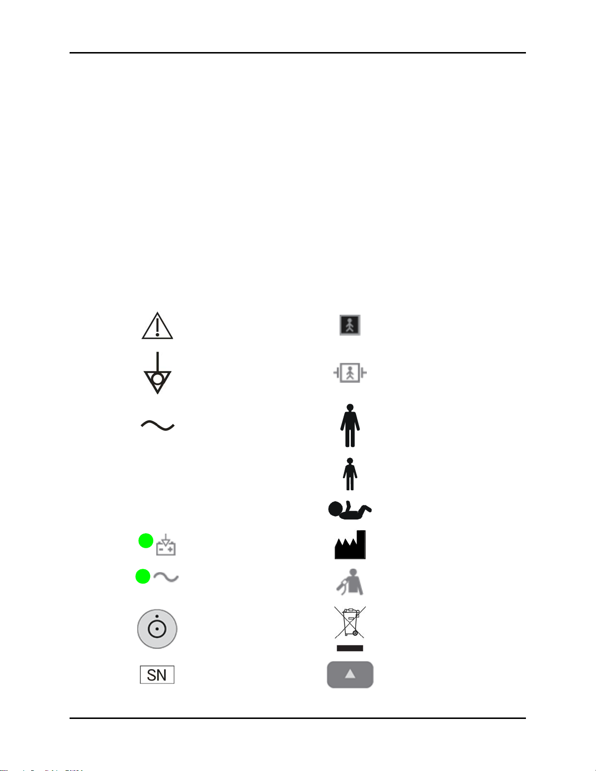
Symbols and Descriptions
SYMBOL DESCRIPTION SYMBOL DESCRIPTION
Attention, Consult
Accompanying Documents /
Refer to Manual
Type BF Equipment
SpO
Equipotentiality
Equipotential grounding
Alternating Current (AC) Adult
Predictive Thermometer
Connector
SpO
Connector Neonate
2
2
Operating on battery power Manufacturer
Connected to AC mains
Power On/Off – Standby Recycle
Defibrillator-proof Type BF
Equipment
Pediatric/Child
NIBP Connector
Serial number Up key
Accutorr V Operating Instructions 0070-10-0699-02 xi
Page 15
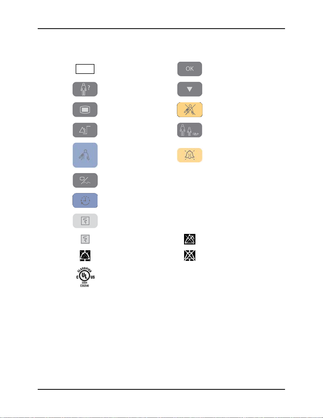
Introduction Symbols and Descriptions
SYMBOL DESCRIPTION SYMBOL DESCRIPTION
REF
Part Number Confirm key
Patient Information key Down key
Main menu key Deflate Cuff key
Set alarms key Patient Size key
Start NIBP key Alarm Silence key
Display Tabular Trends/Pleth
Wav e
NIBP interval key SP1
NC1 Nurse Call connector
RS-232 connector
(Serial Port 1)
Print key (front panel) CS1 Network connector
Print key (recorder)
Alarm Silenced indicator on
LCD display
Alarm Disabled indicator on
LCD display
Audio Alarm Off indicator on
LCD display
Classified by Underwriters Laboratories Inc. with respect to electric shock, fire and
mechanical hazards, only in accordance with UL 60601-1, CAN/CSA C22.2
NO.601-1, IEC 60601-1-1, IEC 60601-2-30, IEC 60601-2-49.
xii 0070-10-0699-02 Accutorr V Operating Instructions
Page 16

1.0
General Description
General Product Description ............................................................................ 1-2
Product Features ............................................................................................. 1-4
Recommended Test and Calibration Frequency................................................... 1-5
Accutorr V Operating Instructions 0070-10-0699-02 1 - 1
Page 17
General Product Description General Description
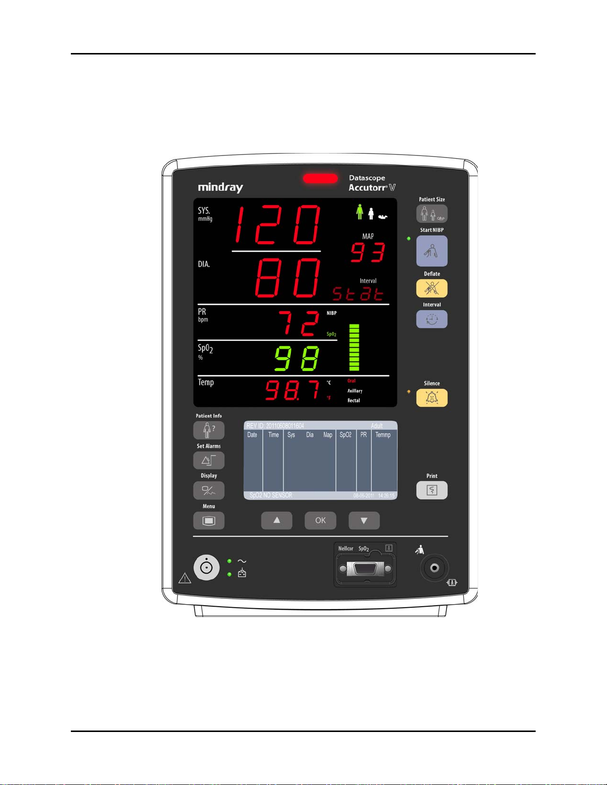
1.1 General Product Description
The Accutorr V monitors vital signs non-invasive blood pressure (NIBP), pulse oxygen
saturation (SpO2), pulse rate (PR), and temperature (Temp) for a single adult, pediatric, or
neonatal patient. Temperature is measured using the optional Temperature Module.
FIGURE 1-1 View of Accutorr V Front Panel
An Accutorr V contains an NIBP module, SpO
and an internal printer.
1 - 2 0070-10-0699-02 Accutorr V Operating Instructions
module, a rechargable Lithium ion battery,
2
Page 18

General Description General Product Description
Product Configurations:
NIBP
MODULE SPO2 MODULE
DPM NIBP DPM SpO
DPM NIBP DPM SpO
DPM NIBP Masimo SET
DPM NIBP Masimo SET
DPM NIBP Nellcor Oximax
DPM NIBP Nellcor Oximax
DPM NIBP - SmarTemp™ Lithium ion Recorder
DPM NIBP --Lithium ion Recorder
NOTE: For any of these configurations, the Barcode Scanner is
optional.
2
2
®
SpO2 (MS-2013) — Lithium ion Recorder
®
SpO2 (MS-2013) SmarTemp™ Lithium ion Recorder
®
SpO2 (NELL-3) — Lithium ion Recorder
®
SpO2 (NELL-3) SmarTemp™ Lithium ion Recorder
All configurations measure NIBP, pulse rate, and SpO
PREDICTIVE
TEMPERATURE
MODULE BATTERY RECORDER
— Lithium ion Recorder
SmarTemp™ Lithium ion Recorder
(optional). The Accutorr V features
2
front panel digital displays for Mean Arterial Pressures, Temperature, and Interval Mode
Timer. It has extra large displays for the Systolic, Diastolic, Pulse Rate, optional Temperature,
and SpO
with a choice of Nellcor, Masimo, or DPM. The Accutorr V incorporates a Liquid
2
Crystal Display (LCD) to view stored measurements and to access system setting menus.
On all units, temperature can be measured with the optional Predictive Thermometer Module
(SmarTemp). All units are equipped with a recorder module for documenting NIBP, pulse rate,
SpO
and temperature information. Each printout includes the time and date of each
2,
measurement.
The Accutorr V stores a maximum of 1,200 groups of measurement data in memory. These
1,200 groups of measurement data are shared by the number of patients that are monitored
(one patient at a time) by the Accutorr V. When only one patient is monitored, the Accutorr V
can store up to 1,200 groups of measurement data for that one patient. When more than
one patient is monitored, the Accutorr V can store any number of measurements for each
patient provided the total number of stored groups of measurement data for all patients
equals 1,200 or less.
The Accutorr V has an Interval Mode that enables the unit to take automatic NIBP
measurements at timed intervals.
Alarm limits can be set for Accutorr V parameters. All alarm violations are indicated by an
audible alarm tone, flashing front panel displays, parenthesis around the violated parameter
on the recorder printouts, and reverse video on the Trend display.
The Accutorr V can operate from a battery.
Accutorr V Operating Instructions 0070-10-0699-02 1 - 3
Page 19

Product Features General Description
1.2 Product Features
Some key features of the Accutorr V are:
• Non-Invasive Blood Pressure (NIBP)
• Pulse Rate
• Nellcor, Masimo, or DPM SpO
•Alarms
•Interval Mode
• Large Light Emitting Diode (LED) Displays
• Trend Memory—Up to 1,200 Measurements
• Communications—Improved ASCII Protocol (DIAP) using straight serial cable
• Nurse Call function
• Universal Power Supply
• User Configured Settings
• Optional Predictive Thermometer Module (SmarTemp)
•Recorder
• High Contrast LCD
• Customer Replaceable Lithium ion Battery
• Universal mounting adapter for rolling stands and wall mounts
• Barcode ready
2
1 - 4 0070-10-0699-02 Accutorr V Operating Instructions
Page 20

General Description Recommended Test and Calibration Frequency
1.3 Recommended Test and Calibration Frequency
CHECK/MAINTENANCE ITEM FREQUENCY
Visual test When first installing or after reinstalling.
Power on test 1. When first installing or after reinstalling.
2. Following any maintenance or replacement of any main unit
part.
NIBP tests Accuracy test 1. If the user suspects that the measurement is incorrect.
Leakage test
Calibration
SpO
test
2
Temperature test
Analog output test If the user suspects that analog output is abnormal.
Bar code scanner test If the user suspects that bar code scan is incorrect.
Electrical safety tests Enclosure leakage
current test
Earth leakage current
test
Patient leakage
current test
Patient auxiliary
current test
Recorder check Following any repair or replacement of the recorder.
2. Following any repairs or replacement of the NIBP module.
3. At least once per year.
1. Following any repair or replacement of the power module.
2. At least once every two years.
Accutorr V Operating Instructions 0070-10-0699-02 1 - 5
Page 21

Recommended Test and Calibration Frequency General Description
This page intentionally left blank.
1 - 6 0070-10-0699-02 Accutorr V Operating Instructions
Page 22

2.0
Controls and Indicators
Introduction.................................................................................................... 2-2
Front Panel .................................................................................................... 2-3
Rear Panel..................................................................................................... 2-7
Recorder Module............................................................................................ 2-8
Accutorr V Operating Instructions 0070-10-0699-02 2 - 1
Page 23

Introduction Controls and Indicators
2.1 Introduction
This section of the Operating Instructions identifies and describes each control and display of
the Accutorr V. For step-by-step operating instructions, see Chapter 3.0.
The following is a list of all controls, connectors, and indicators, their item numbers and the
page numbers. The item number refers to the call-outs on the drawings within this chapter.
The page number refers to the page where the item description is found.
FRONT PANEL PAGE FRONT PANEL PAGE
1. Alarm lamp 2-3 25. DEFLATE key 2-5
2. Systolic pressure (SYS) 2-4 26. INTERVAL key 2-6
3. Mean pressure (MAP) 2-4 27. NIBP Interval indicator 2-6
4. Diastolic pressure (DIA) 2-4 28. Pulse strength indicator 2-6
5. Pulse Rate (PR) Source indicator 2-4 29. SILENCE key 2-6
6. Pulse rate (PR) 2-4 30. Silence indicator 2-6
7. Oxygen saturation (SpO2) 2-4 31. Temperature site 2-6
8. Temperature (Temp) 2-4 32. Temperature Unit indicator 2-6
9. PATIENT INFO key 2-4 33. PRINT key 2-6
10. SET ALARMS key 2-4 34. NIBP connector 2-6
11. DISPLAY key 2-4 REAR PANEL
12. MENU key 2-4 35. TEMP probe sheath 2-7
13. ON/STANDBY key/indicator 2-4 36. TEMP probe covers 2-7
14. AC power indicator 2-4 37. TEMP probe connector 2-7
15. Battery status indicator 2-5 38. RS-232 connector 2-7
16. UP ARROW key 2-5 39. Nurse call connector 2-7
17. LCD Display 2-5 40. Network connector 2-8
18. OK key 2-5 41. Equipotential grounding connector 2-8
19. DOWN Arrow key 2-5 42. AC power input connector 2-8
20. SpO2 Connector 2-5 RECORDER MODULE
21. Patient size indicator 2-5 43. Paper outlet 2-8
22. NIBP status indicator 2-5 44. Recorder door 2-8
23. PATIENT SIZE key 2-5 45.
24. START NIBP key 2-5 46. Recorder door latch 2-8
Power indicator 2-8
2 - 2 0070-10-0699-02 Accutorr V Operating Instructions
Page 24
Controls and Indicators Front Panel
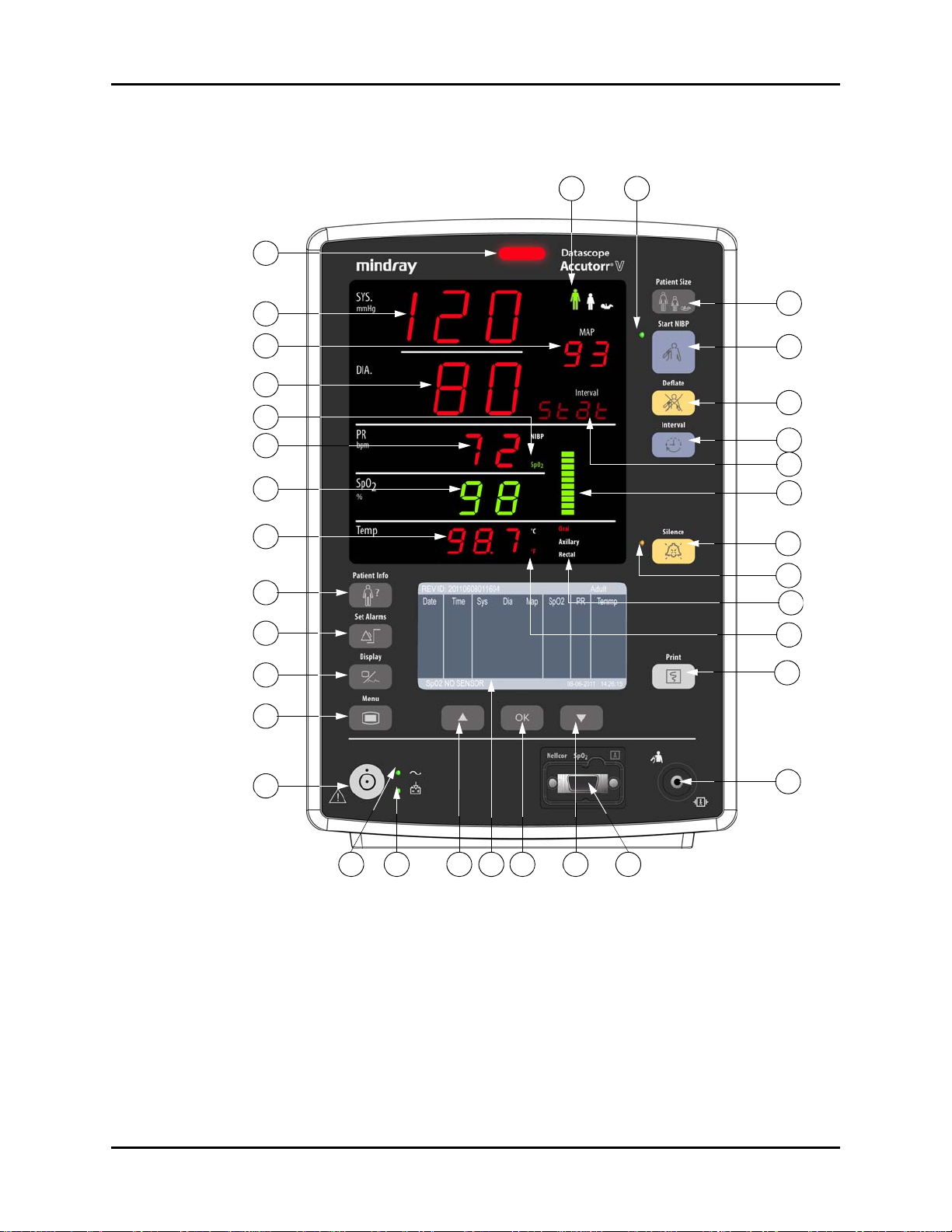
2.2 Front Panel
2221
1
10
11
12
2
3
4
5
6
7
8
9
23
24
25
26
27
28
29
30
31
32
33
13
15 18
14
16
17
19
20
34
FIGURE 2-1 Accutorr V Front Panel
NOTE: The numbers in parentheses ( ) refer to the items described
as follows and shown in Figures 2-1 through 2-3.
1. Alarm lamp
Flashes red for a high priority alarm and shows continuous yellow for a low priority alarm.
NOTE: In the event that a high alarm and a low alarm occur
simultaneously, only the high priority red lamp flashes.
Accutorr V Operating Instructions 0070-10-0699-02 2 - 3
Page 25

Front Panel Controls and Indicators
2. Systolic pressure (SYS)
The value of systolic pressure is obtained by the NIBP module. When no other LEDs illuminate
and the SYS LED displays three (3) flashing dashes and the LCD display (17) is blank, the
Accutorr V is in the standby state.
3. Mean pressure (MAP)
The value of mean pressure is obtained by the NIBP module.
4. Diastolic pressure (DIA)
The value of diastolic pressure is obtained by the NIBP module.
5. Pulse Rate (PR) Source indicator
The PR source is either SpO
or NIBP.
2
6. Pulse rate (PR)
The value of the pulse rate is obtained by the NIBP module or SpO
module. The PR unit is
2
beats per minute (bpm).
7. Oxygen saturation (SpO2)
The monitor displays the SpO
value in %.
2
8. Temperature (Temp)
The monitor displays the temperature value in degrees C or degrees F, selectable in the Temp
SETUP dialog. The currently applied unit is illuminated as shown in callout (32).
9. PATIENT INFO key
Press to switch to the PATIENT INFORMATION dialog and automatically create a patient ID.
10. SET ALARMS key
Press to switch between the SET ALARMS dialog and the Trend display.
11. DISPLAY key
Press to switch between the PLETH display and Trend display.
12. MENU key
Press to switch between the SYSTEM SETUP dialog and the Trend display.
13. ON/STANDBY key/indicator
Press to turn the monitor on or off or to enter/exit the standby state. In the operating state,
press and hold for less than 1second to switch the device to standby. To turn off the monitor,
press and hold for more than 2 seconds.
Inside this key there is a working status indicator:
• Illuminated: Indicates the monitor is powered on.
• Dark: Indicates the monitor is powered off.
14. AC power indicator
• Illuminated: Indicates the AC power is connected.
2 - 4 0070-10-0699-02 Accutorr V Operating Instructions
Page 26

Controls and Indicators Front Panel
• Dark: Indicates the AC power is not connected.
15. Battery status indicator
• Illuminated: Indicates the unit is on and the battery is inserted.
• Flashes: Indicates the system is on and in low battery status.
• Dark: Indicates the battery is not inserted. The battery indicator also remains
dark when monitor power is off.
16. UP ARROW key
Moves the cursor up within the LCD display (17).
17. LCD Display
Displays startup screen, menus, trend data, PLETH waveforms, and current date and time.
18. OK key
Selects the highlighted option. In the trend view, pressing this key displays the REVIEW
SETUP dialog.
19. DOWN Arrow key
Moves the cursor down within the LCD display (17).
20. SpO
Connector
2
Used to attach an SpO2 sensor to the Accutorr V.
21. Patient size indicator
Patient sizes include adult, pediatric, or neonate from left to right.
22. NIBP status indicator
• Illuminated: Indicates the monitor is ready to perform an NIBP measurement.
• Dark: Indicates that interval NIBP measurement is in progress or device not
ready to perform an NIBP measurement.
23. PATIENT SIZE key
Changes the patient size by cycling through adult, pediatric, and neonate. Patient size
changes only when this key is pressed and held for one second.
24. START NIBP key
Starts an NIBP measurement.
25. DEFLATE key
Stops an NIBP measurement that is in progress and deflates the cuff. Pressing this key while
in the interval mode suspends the interval mode operation until the Start NIBP key is pressed
again.
NOTE: Interval display flashes between pressing the Deflate key
Accutorr V Operating Instructions 0070-10-0699-02 2 - 5
and pressing the Start NIBP key.
Page 27

Front Panel Controls and Indicators
26. INTERVAL key
Changes the NIBP measuring mode and interval by cycling through the modes and intervals
displayed in the NIBP Interval indicator (27), as follows:
OFF (manual), STAT, or 1, 2, 3, 5, 10, 15, 20, 30, 60, 120, 240 minutes
Pressing and holding the Interval key for 3 seconds directly goes to OFF, i.e. the manual
mode.
27. NIBP Interval indicator
Indicates the current NIBP measuring mode or interval.
28. Pulse strength indicator
Indicates the patient’s relative pulse strength by the number of stacked bars.
29. SILENCE key
A quick press of this key pauses the current alarm for two (2) minutes, after which alarm tone
resumes if alarm limits are still violated. If a new alarm condition occurs during the two (2)
minutes, a new alarm tone sounds. Pressing and holding this key for more than two (2)
seconds disables alarm tones indefinitely. If a new alarm condition occurs while in this state,
the monitor automatically exits the alarm silenced state.
30. Silence indicator
• Dark (Normal state): when an alarm occurs, the monitor presents an alarm tone,
visual indication, and message according to the alarm level.
• Illuminated: Alarm silenced state: when an alarm occurs, the monitor presents a
visible alarm and alarm message, but no alarm tone is given. If a new alarm condition
occurs, the monitor automatically exits the alarm silenced state.
• Flash (Alarm paused status): when an alarm occurs, the monitor displays a visible
alarm and alarm message, but no alarm tone is given. The alarm paused time is 120
seconds, after which the alarm tone sounds again if alarm limits are still violated. The
unit counts down the 120 seconds on the LCD Display (17) in place of the date and
time. If a new alarm occurs during this period, the monitor automatically exits the
alarm paused state.
31. Temperature site
The temperature measuring position and monitoring mode, oral, auxiliary, and rectal
selection illuminates.
32. Temperature Unit indicator
The current temperature unit.
33. PRINT key
Starts or stops the recorder.
34. NIBP connector
Used to attach the specified NIBP hose to the Accutorr V.
2 - 6 0070-10-0699-02 Accutorr V Operating Instructions
Page 28
Controls and Indicators Rear Panel
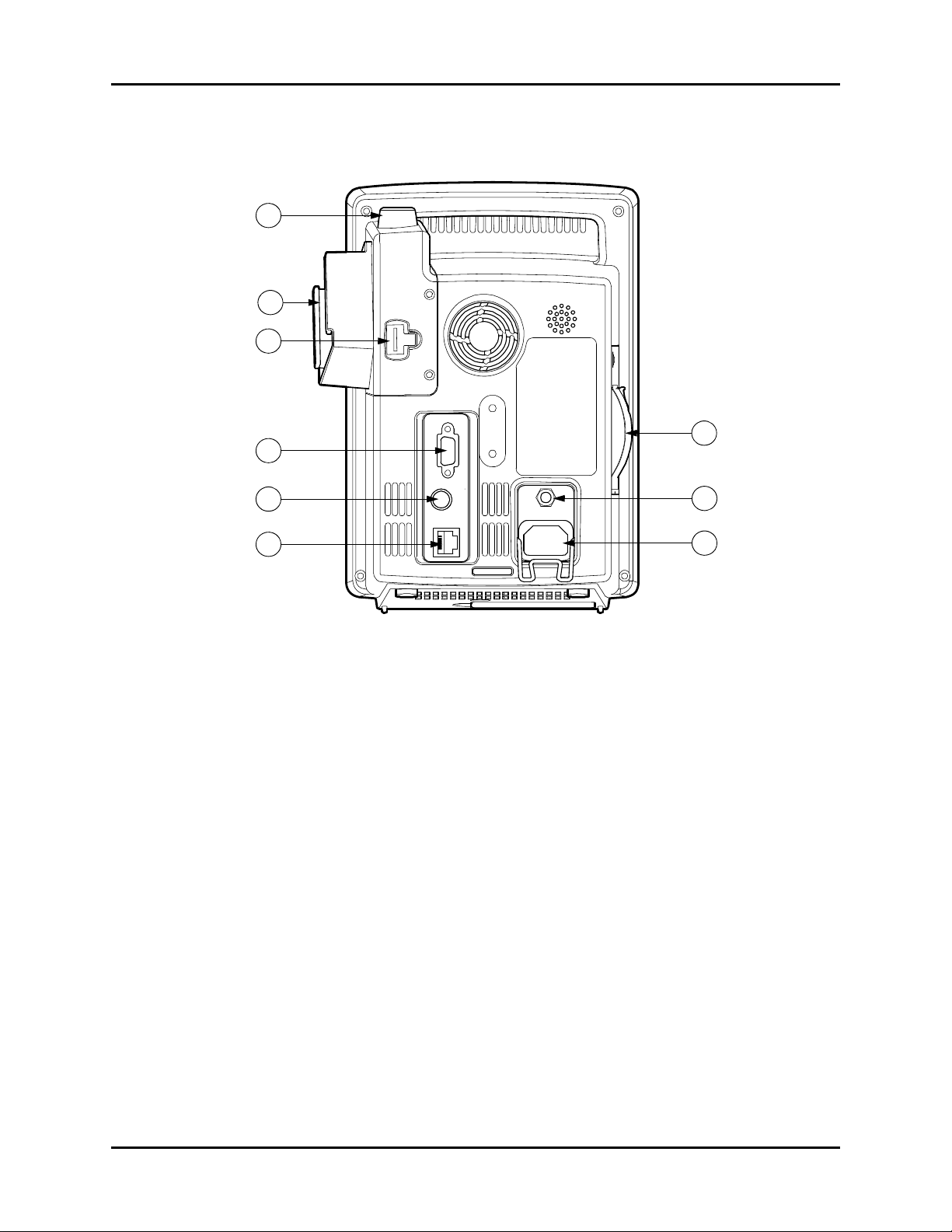
2.3 Rear Panel
35
36
37
41
38
39
40
42
43
FIGURE 2-2 Accutorr V — Rear Panel
35. TEMP probe sheath
Holds the temperature probe when not in use.
36. TEMP probe covers
Holds the temperature probe covers for easy access.
37. TEMP probe connector
Used to attach a temperature probe to the Accutorr V.
NOTE: The Temperature Module is an optional kit.
38. RS-232 connector
Used to attach a bar code scanner or DIAP.
NOTE: When the RS-232 connector is used for DIAP, barcode power
must be set to OFF. Refer to Section 3.16.1 for turning
BARCODE POWER to OFF.
39. Nurse call connector
Provides compatible communication from the Accutorr V to the hospital’s nurse call system.
NOTE: All equipment attached to the communications ports on the
Accutorr V must meet the requirements as specified in
EN 60601-1-1.
Accutorr V Operating Instructions 0070-10-0699-02 2 - 7
Page 29
Recorder Module Controls and Indicators
40. Network connector
For software updates only.
41. Recorder
Recorder for printing trend data and PLETH waveform.
42. Equipotential grounding connector
Used to connect the equipotential grounding connectors of other devices.
43. AC power input connector
Connects the monitor to the AC power through a 3-core power cable.
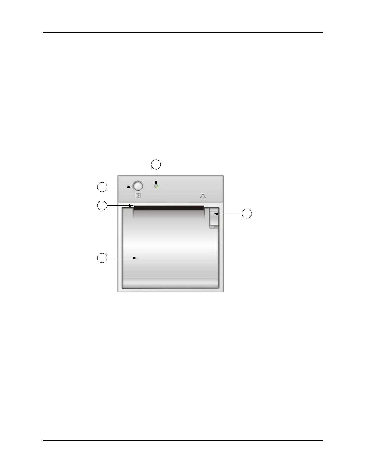
2.4 Recorder Module
47
44
45
46
FIGURE 2-3 Accutorr V — Recorder Module
44. Print button
Prints the PLETH curve or the trend data on the current display.
45. Paper outlet
Recorder feeds paper out of slot.
46. Recorder door
Access to paper roll.
48
47. Power indicator
Indicates power to the recorder.
48. Recorder door latch
Secures the recorder door.
2 - 8 0070-10-0699-02 Accutorr V Operating Instructions
Page 30

3.0
Operation
Introduction.................................................................................................... 3-2
Operator Position ........................................................................................... 3-2
Setting-up and Turning Power On ..................................................................... 3-2
Standby and Power OFF ................................................................................. 3-4
Patient Setup.................................................................................................. 3-6
Manual NIBP Measurements ............................................................................ 3-11
Automatic NIBP Measurements (Interval Mode) .................................................. 3-14
Alarms .......................................................................................................... 3-17
Viewing and Deleting Stored Trend Data........................................................... 3-21
Common Setup .............................................................................................. 3-24
SpO2 Measurements ...................................................................................... 3-26
Temperature Measurement ............................................................................... 3-34
Recorder ....................................................................................................... 3-39
Setting The Clock (Date and Time) .................................................................... 3-40
Battery Operation........................................................................................... 3-41
Creating a User Configuration ......................................................................... 3-42
Status and Error Codes ................................................................................... 3-47
Accutorr V Operating Instructions 0070-10-0699-02 3 - 1
Page 31

Introduction Operation
3.1 Introduction
This section of the Operating Instructions provides guidelines and step-by-step instructions for
proper operation of the Accutorr V. The numbers in parentheses ( ) refer to the items
described in Chapter 2.0 , “Controls and Indicators” and shown in Figures 2-1 through 2-3.
3.2 Operator Position
The operator of the device should be positioned in front of the Accutorr V Patient Monitoring
Display at a distance of no more than 1m.
3.3 Setting-up and Turning Power On
1. Before turning the power on, check the rear panel for voltage requirements. Confirm
proper voltage is available and install the battery.
2. Optional – Attach a serial cable to the 9-pin rear panel RS-232 connector (38).
CAUTION: The Communications Connectors on the Accutorr V are only
for use with IEC 60601-1-1 compliant equipment.
3. Attach the AC power cord into the rear panel AC power input connector (43) and into a
grounded (3-prong) hospital grade AC receptacle. Do not use an adapter to defeat the
ground. The AC power indicator (14) illuminates, indicating AC power has been
applied. The internal battery charges automatically when AC power is applied. The
Accutorr V operates from the AC mains and can be operated from its internal battery.
4. Press (13) to activate the unit.
• The system beeps indicating the software has loaded.
• All the LEDs on the front panel light up.
• The technical alarm lamp turns yellow, red, then turns off to indicate the self test related
to alarm lamps passed.
• After the Accutorr V initializes, the start-up screen clears, and the Trend display shows
in the LCD Display (17) (see FIGURE 3-1).
NOTE: If an error occurs during the power-up sequence, see Section
3.17.3.
3 - 2 0070-10-0699-02 Accutorr V Operating Instructions
Page 32

Operation Setting-up and Turning Power On
Patient ID Patient Size
Message Area
Date and Time
FIGURE 3-1 Example LCD Display (17)
5. Optional – To set the time and date, refer to section 3.14 for instructions.
6. Optional – To adjust the contrast on the LCD, refer to section 3.10.2, “Setting the LCD
Brightness and Contrast”.
7. Test the recorder by pressing (33). The recorder prints a real time waveform to
verify proper function.
8. If the optional Temperature module kit is installed, test the predictive thermometer by
removing the probe from its holder.
9. Verify that the message “Temp Warming Up” displays, followed by the message
“Predictive Temp Ready” and a double beep.
Accutorr V Operating Instructions 0070-10-0699-02 3 - 3
Page 33

Standby and Power OFF Operation
3.4 Standby and Power OFF
3.4.1 Entering Standby
1. Press (13) for less than 1 second to put the monitor in standby mode.
2. In the dialog on the LCD Display (17), confirm entering standby by pressing (18).
3.4.2 Exiting Standby
1. Press any key on the device.
2. In the dialog on the LCD Display (17), confirm exiting standby by pressing (18).
NOTE: The monitor exits standby mode when it receives SpO2
Once the monitor exits Standby mode, it enables alarms, restores all functions, restores
communication, and starts to save trend data.
physiological signals or the temp probe is removed from the
sheath.
3.4.3 Turning Power Off
Press (13) for two (2) seconds or more to turn off the monitor.
NOTE: Disconnect the Accutorr V from the mains to isolate it from
the mains power during an emergency.
3.4.4 Selecting a Configuration
When power to the Accutorr V is turned on, it automatically loads one of three
configurations.
•The FACTORY DEFAULT (or FACTORY CONFIG) is installed by the factory and
cannot be modified.
•The USER CONFIG is created by following the steps in Section 3.16.5.
•The LAST CONFIG consists of the parameter settings in use before the unit was
powered off.
To select a configuration to be loaded at power-on, follow the steps in Section 3.16.6.
To load a user configuration or factory default configuration after the Accutorr V is powered
on:
1. Press (12) to display the SYSTEM SETUP dialog as shown in FIGURE 3-2.
3 - 4 0070-10-0699-02 Accutorr V Operating Instructions
Page 34

Operation Standby and Power OFF
FIGURE 3-2 SYSTEM SETUP Dialog
2. Press (16) or (19) to highlight DEFAULT to display the DEFAULT dialog as
shown in FIGURE 3-3.
FIGURE 3-3 DEFAULT Configuration Load Dialog
3. Press (16) or (19) to highlight a configuration to load.
4. Once the choice is highlighted, press (18) to select it.
5. Press (12) to display the SYSTEM SETUP dialog.
6. Press (12) again to display the main screen.
Accutorr V Operating Instructions 0070-10-0699-02 3 - 5
Page 35

Patient Setup Operation
3.5 Patient Setup
3.5.1 Entering Patient Information
Patient information in the Accutorr V monitor consists of the PATIENT ID and the PATIENT
TYPE as shown in FIGURE 3-4.
FIGURE 3-4 Example PATIENT INFORMATION Dialog
To enter patient information:
1. Press (9) to display the PATIENT INFORMATION dialog.
2. Scan the patient ID barcode to enter the PATIENT ID.
NOTE: After connecting the barcode scanner to the Accutorr V,
follow the steps in Section 3.16.1 to turn BARCODE POWER
on.
NOTE: Each time the monitor is turned on, it generates a new
PATIENT ID. If Quick Admit is on and (9) is pressed, the
monitor generates a new PATIENT ID. Scanning the patient
ID barcode replaces the generated PATIENT ID. If Quick
Admit is off and (9) is pressed, the monitor does not
generate a new PATIENT ID. To turn Quick Admit on or off,
see Section 3.5.1.1.
3. Press (16) or (19) to select the PATIENT TYPE (patient size) field. See
Section 3.5.2 to select a patient size without using the PATIENT INFORMATION dialog.
4. Once the field is highlighted, press (18) to select it.
5. Press (16) or (19) to select the PATIENT TYPE (patient size).
6. Once the choice is highlighted, press (18) to select it.
7. Press (16) or (19) to highlight OK.
8. Press (18) to return to the Trend display mode.
• The patient size indicator (21) displays the new patient size.
• Select CANCEL and then press (18) to cancel the patient type change.
3 - 6 0070-10-0699-02 Accutorr V Operating Instructions
Page 36

Operation Patient Setup
3.5.1.1 Quick Admit
To turn Quick Admit on or off:
1. Press (12) to display the SYSTEM SETUP dialog as shown in FIGURE 3-2.
2. Press (16) or (19) to highlight MAINTENANCE.
3. Once MAINTENANCE is highlighted, press (18) to display the
MAINTENANCE dialog as shown in FIGURE 3-5.
FIGURE 3-5 MAINTENANCE dialog
NOTE: The VERSION and IP ADDRESS SETUP selections in the
MAINTENANCE dialog (FIGURE 3-5) are used by service. See
the Service Manual, part number 0070-10-0702.
4. Press (16) or (19) to highlight the QUICK ADMIT field.
5. Once the QUICK ADMIT field is highlighted, press (18) to enable the QUICK
ADMIT field.
6. Press (16) or (19) to turn Quick Admit on or off.
7. Press (18) to keep the new setting.
8. Press (12) to display the SYSTEM SETUP dialog.
9. Press (12) again to return to the Trend display mode.
3.5.2 Selecting the Patient Size
Select patient size using one of the two methods:
• Press (9) to display the PATIENT INFORMATION dialog (see Section 3.5.1).
• Press (23) as follows.
Adult
Pediatric
Neonate
FIGURE 3-6 Patient Size Graphics and Indicators (21)
Accutorr V Operating Instructions 0070-10-0699-02 3 - 7
Page 37

Patient Setup Operation
To select the Patient Size, press (23). Three choices are available: Adult, Pediatric,
and Neonate. The patient size changes with each key press.
The Patient size indicator (21) illuminates to indicate the selected size as shown in
FIGURE 3-6. The factory default Patient Size setting is Adult.
NOTE: Selecting Neonate patient size changes Temperature site
(31) to Axiliary. The temperature site will default to oral
when Adult patient size is selected.
3.5.3 Setting Initial Cuff Inflation Pressure
The initial cuff inflation pressure depends on the Patient Size setting. The initial cuff inflation
pressures are listed in the following table.
PATIENT SIZE
SETTING
Adult 180 mmHg 100 mmHg 280 mmHg 5 mmHg
Pediatric 140 mmHg 60 mmHg 180 mmHg 5 mmHg
Neonate 100 mmHg 40 mmHg 120 mmHg 5 mmHg
NOTE: The default patient size and initial cuff inflation pressure can
FACTORY DEFAULT
INITIAL CUFF
INFLATION VALUES
be customized.
LOWEST
SELECTABLE
PRESSURE
HIGHEST
SELECTABLE
PRESSURE INCREMENT
To modify the initial cuff inflation pressure:
1. Press (12) to display the SYSTEM SETUP dialog as shown in FIGURE 3-7.
2. Press (16) or (19) to highlight MAINTENANCE.
FIGURE 3-7 SYSTEM SETUP Dialog
3. Once MAINTENANCE is highlighted, press (18) to display the MAINTENANCE
dialog as shown in FIGURE 3-8.
3 - 8 0070-10-0699-02 Accutorr V Operating Instructions
Page 38

Operation Patient Setup
FIGURE 3-8 MAINTENANCE dialog
4. Press (16) or (19) to highlight NIBP TOOLS to display the NIBP TOOLS
dialog as shown in FIGURE 3-9.
5. Once NIBP TOOLS is highlighted, press (18) to display the NIBP TOOLS dialog.
FIGURE 3-9 NIBP TOOLS Dialog
NOTE: The ACCURACY TEST, LEAK TEST, and CALIBRATION selection
shown the NIBP TOOLS dialog (FIGURE 3-9) are explained in
the Service Manual, part number 0070-10-0702. Calibration
should be carried out by qualified personnel only.
6. Press (16) or (19) to highlight INITIAL PRESSURE to display the INITIAL
PRESSURE dialog as shown in FIGURE 3-10.
7. Once INITIAL PRESSURE is highlighted, press (18) select it.
FIGURE 3-10 Example NIBP Cuff Initial Pressure Dialog
Accutorr V Operating Instructions 0070-10-0699-02 3 - 9
Page 39

Patient Setup Operation
8. Press (16) or (19) to highlight an initial cuff pressure to change.
9. Once the initial cuff pressure is highlighted, press (18) to select it.
10. Press (16) or (19) to change the initial cuff pressure value.
11. Once the desired pressure is displayed, press (18) to set it.
12. Repeat steps 8 through 11 as needed.
13. Once the initial cuff pressure values are set, press (16) or (19)until OK is
selected.
14. Once OK is selected, press (18) to accept the new cuff pressure values and exit
the INITIAL PRESSURE dialog to the NIBP TOOLS dialog.
NOTE: Select CANCEL and then press (18) to cancel the
operation and exit the INITIAL PRESSURE dialog without
changing the initial pressure values.
3 - 10 0070-10-0699-02 Accutorr V Operating Instructions
Page 40

Operation Manual NIBP Measurements
3.6 Manual NIBP Measurements
The Accutorr V calculates NIBP values using the oscillometric method of noninvasive blood
pressure measurement. These measurements correspond to comparisons with auscultatory
values, measured using the fifth Korotkoff sound within ANSI/AAMI SP10 standards for
accuracy.
1. Select a pressure cuff that is appropriate for the patient size. Use the following chart as
a guideline.
LIMB
CIRCUMFERENCE*
REUSABLE CUFFS – QUICK CONNECT– LATEX FREE*
10 – 19 cm Small Child 0683-15-0001-01
18 – 26 cm Small Adult 0683-15-0002-01
25 – 35 cm Adult 0683-15-0003-01
33 – 47 cm Large Adult 0683-15-0004-01
46 – 66 cm Adult Thigh 0683-15-0005-01
25 – 35 cm Adult Long 0683-15-0006-01
33 – 47 cm Large Adult Long 0683-15-0007-01
SINGLE PATIENT USE CUFFS – QUICK CONNECT– LATEX FREE**
10 – 19 cm Small Child 0683-14-0001-01 (box of 10)
18 – 26 cm Small Adult 0683-14-0002-01 (box of 10)
25 – 35 cm Adult 0683-14-0003-01 (box of 10)
33 – 47 cm Large Adult 0683-14-0004-01 (box of 10)
46 – 66 cm Adult Thigh 0683-14-0005-01 (box of 5)
25 – 35 cm Adult Long 0683-14-0006-01 (box of 10)
33 – 47 cm Large Adult Long 0683-14-0007-01 (box of 10)
SINGLE PATIENT USE CUFFS – QUICK CONNECT– LATEX FREE**
(REQUIRES HOSE P/N 0683-04-0003)
3 – 6 cm Neonatal, Size 1 0683-23-0001 (box of 10)
5 – 8 cm Neonatal, Size 2 0683-23-0002 (box of 10)
7 – 10 cm Neonatal, Size 3 0683-23-0003 (box of 10)
9 – 13 cm Neonatal, Size 4 0683-23-0004 (box of 10)
12 – 17 cm Neonatal, Size 5 0683-23-0005 (box of 10)
* The limb circumferences of cuffs adhere to the American Heart Association (AHA) guidelines for size.
They also incorporate index and range lines to assist in cuff selection.
** Do not reuse single patient use cuffs.
DESCRIPTION /
CUFF NAME PART NUMBER
NOTE: The Accutorr V cuffs have special quick connect connectors.
WARNING: To ensure proper performance and safety and to prevent
the voiding of the warranty, only use authorized parts and
accessories with the Accutorr V. Use of unauthorized
accessories may result in erroneous readings.
The limb pressure may not fall to zero between measurements if the cuff is wrapped too
tightly. Therefore, assure that the cuff is properly applied.
Accutorr V Operating Instructions 0070-10-0699-02 3 - 11
Page 41

Manual NIBP Measurements Operation
The skin is sometimes fragile (i.e., on pediatrics, geriatrics, etc.). In these cases, consider a
longer timer interval to decrease the number of cuff inflations over a period of time.
NOTE: In extreme cases, a thin layer of soft roll or webril cotton
padding may be applied to the limb in order to cushion the
skin when the cuff is inflated. This measure may affect NIBP
performance and should be used with caution.
2. Attach the cuff hose to the NIBP connector (34) by holding the hose behind the knurled
pressure fitting (female). Push onto the male connector until a “click” is heard. To
remove, hold the knurled female fitting and pull firmly to release.
3. Apply the cuff to the patient. To reduce errors, the cuff should fit snugly, but with enough
room for two fingers to be placed between the cuff and the patient’s arm (on adults), and
with little or no air present within the cuff. The cuff should fit loosely on neonates. Apply
the cuff so that the center of the inflation bag (bladder) is over the brachial artery. Be
sure that the INDEX line on the cuff falls between the two RANGE lines. If not, a larger or
smaller cuff is required. Be sure the cuff lies directly against the patient’s skin. For best
results, the cuff should be placed on the arm at heart level, and no clothing should come
between the patient and the cuff.
NOTE: Avoid compression or restriction of the pressure hose. Do
not place the NIBP cuff on a limb that is being utilized for
any other medical procedure. For example, an I.V. Catheter.
4. If required, select the Patient Size with (23). On initial power up, the configurable
default setting is used. Otherwise, the last selected patient size is used. Initial default cuff
inflation pressure depends on the Patient Size setting. See section 3.5.3 for details on
changing the initial cuff inflation pressure.
5. Press (24) to begin an NIBP measurement. During inflation and deflation of the
cuff, the Accutorr V displays the bladder pressure in the MAP display.
NOTE: Inflate the cuff only after proper application to the patient’s
limb. Cuff damage can result if the cuff is left unwrapped
and then inflated.
The cuff begins to inflate to the selected cuff pressure. After reaching the selected pressure,
the cuff begins to slowly deflate, and the Accutorr V collects oscillometric pulsations.
If the unit detects inadequate initial cuff inflation, the unit retries with a higher inflation
pressure (+50 mmHg in the adult and pediatric modes; +40 mmHg in the neonate mode).
Have the patient remain still to avoid unnecessary motion artifact. After the cuff pressure
drops below the diastolic pressure, the results of the measurement are displayed, and the cuff
deflates.
NOTE: When required, press (25) to interrupt a
NOTE: Once the initial measurement is taken, the Accutorr V
NOTE: Check the patient’s limb for any indications of circulation
3 - 12 0070-10-0699-02 Accutorr V Operating Instructions
measurement and deflate the cuff.
continues to use the selected patient size.
impairment.
Page 42

Operation Manual NIBP Measurements
3.6.1 NIBP Pressure Limit Fail Safe
If the cuff is over-pressurized, it will automatically deflate, and “OVER PRESSURE” displays as
an error message on the LCD Display (17).
Before taking a new measurement, press (24) to clear an over-pressure message.
3.6.2 Cuff Inflation Time
If the cuff pressure does not attain 15 mmHg within 20 seconds for adult and pediatric
patients or 15 mmHg within 10 seconds for neonate patients from the start of inflation or if
the target pressure is not reached within another 60 seconds, the cuff is deflated, and status
codes display. See Section 3.17 for a list of error and status codes.
3.6.3 Automatic Retry
If an NIBP measurement fails, the Accutorr V retries measuring up to three times. The
message “NIBP RETRY” is displayed after the cuff deflates. If the measurement fails all three
retries, the LCD Display (17) shows the Sys, Dia, and Map values as “XXX” and PR as “–” if
SpO
not providing the pulse rate.
2
Accutorr V Operating Instructions 0070-10-0699-02 3 - 13
Page 43

Automatic NIBP Measurements (Interval Mode) Operation
3.7 Automatic NIBP Measurements (Interval Mode)
The Accutorr V can be set to automatically take NIBP measurements. When first placed in
service and powered up, the interval setting defaults to OFF. Use the User Configuration
mode to set custom defaults for the Interval Mode. See section 3.16, ‘Creating a User
Configuration’ for details. In this mode, adaptive inflation is always enabled.
WARNING: Continued use of the STAT NIBP mode or short term
automatic mode may result in surface vessel rupture
(petechia).
3.7.1 Starting an Automatic Measurement
Follow steps 1 through 4 in the manual NIBP measurement procedure, section 3.6, to select
the cuff, attach and apply the cuff, and to adjust the initial cuff inflation pressure. Then do the
following:
1. Press (26) to display the current selection in the NIBP Interval indicator (27).
2. Press (26) to scroll through the interval selections.
The selections are OFF, STAT, 1, 2, 3, 5, 10, 15, 20, 30, 60, 120, 240 minutes.
3. Press (24) to take a measurement and to activate the interval mode.
NOTE: When the NIBP STAT interval is chosen, the Accutorr V takes
back to back (one right after the other) blood pressure
readings. As a safety precaution, there is a five minute or
10 measurement limit for continuous NIBP measurements.
After 5 minutes or 10 measurements, the NIBP module
automatically switches to the mode in use before NIBP STAT
was selected. This reduces the chance of surface vessel
rupture (petechia).
3.7.2 Canceling an Automatic NIBP Measurement
To cancel a scheduled measurement, press (25), which suspends the timed NIBP
measurements until (24) is pressed. The interval indicator flashes. See section 3.7.4
for more details on the start and deflate function.
NOTE: Pressing (25) also ends a measurement cycle that is
already in progress.
To take an immediate measurement and to reactivate the Interval mode, press (24).
The Accutorr V continues the interval mode. For example, if the interval was set to 30
minutes, the next timed measurement will be 30 minutes after pressing .
NOTE: If the Interval mode is no longer required, set the interval to
OFF prior to pressing (24). See section 3.7 for details
on changing the interval mode.
3 - 14 0070-10-0699-02 Accutorr V Operating Instructions
Page 44

Operation Automatic NIBP Measurements (Interval Mode)
NOTE: If (25) is pressed, there is a 1 – 2 second delay before
another measurement can be taken. The Accutorr V
illuminates the NIBP status indicator (22) when ready.
3.7.3 Changing the Interval Setting
If the INTERVAL mode is active and the interval time is changed (follow steps 1 through 3 in
section 3.7.1), the measurement cycle is reset with the new interval. Measurement resumes
after the new interval time elapses.
For example: The interval time is set to 60 minutes. Thirty minutes have elapsed since the last
timed automatic measurement and the interval time is changed to 10 minutes. Once the
interval time is entered, the Accutorr V will take an automatic NIBP measurement in 10
minutes and then once every 10 minutes.
3.7.4 START and DEFLATE Functions
The START NIBP and DEFLATE functions have the following effects on the timed measurement
sequence.
If the INTERVAL mode is active, the NIBP module instantly begins a
measurement. Taking this unscheduled measurement does not affect the
timing of the interval cycle, therefore, the scheduled measurements will
START NIBP key
(24)
DEFLATE key (25)
still be taken as if there were no interruptions. Only one measurement is
taken for each measurement cycle - even if the unscheduled
measurement coincides with the scheduled measurement.
If a measurement is in progress, the measurement is suspended and the
cuff deflates. If the INTERVAL mode is active with a measurement in
progress, no additional measurements are taken until the START NIBP
key (24) is pressed.
3.7.5 Automatic Adjustment of Cuff Inflation Pressure (Adaptive Inflation)
The Accutorr V adjusts the inflation pressure according to the previous reading of the systolic
pressure. After the first successful measurement, the inflation pressure is the previous systolic
+50 mmHg in the adult and pediatric modes, or +40 mmHg in the neonate mode. If a
manual measurement is taken between interval readings, the manual measurement uses
Adaptive Inflation because the unit is in Interval Mode.
NOTE: When not in Interval mode, Adaptive Inflation is disabled.
To view the current initial inflation pressure, follow the steps in Section 3.5.3. Press
(16) or (19) to change the inflation pressure.
Accutorr V Operating Instructions 0070-10-0699-02 3 - 15
Page 45

Automatic NIBP Measurements (Interval Mode) Operation
3.7.6 Automatic Retry
If an NIBP measurement fails, the Accutorr V retries measuring up to three times. The
message “NIBP RETRY” is displayed after the cuff deflates. If the measurement fails all three
retries, the LCD Display (17) shows the Sys, Dia, and Map values as “XXX” and PR as “–” if
SpO
not providing the pulse rate.
2
3 - 16 0070-10-0699-02 Accutorr V Operating Instructions
Page 46

Operation Alarms
3.8 Alarms
The Accutorr V provides HI (high) and LO (low) alarm limit settings for systolic, diastolic,
MAP, pulse rate, and SpO
equals or exceed the specified alarm limits.
NOTE: The audio alarm complies with the requirements of
IEC60601-1-8.
The measured sound pressure level for the high audio alarm is 75.4 dB.
The measured sound pressure level for the low audio alarm is 47 dB.
3.8.1 Setting Alarm Limits
The factory and custom defaults for alarms can be changed as required to accommodate the
needs of individual patients.
Pressing (10) toggles between the Trend display and the SET ALARMS dialog shown in
FIGURE 3-11.
. An alarm violation occurs when one or more patient parameters
2
FIGURE 3-11 Example SET ALARMS Dialog
1. Press (10) to display the SET ALARMS dialog.
2. Press (16) or (19) to highlight a HI or LO alarm limit.
3. Once the alarm limit is highlighted, press (18) to select it.
4. Press (16) or (19) to change the alarm limit values.
NOTE: The high end of a HI (high) alarm limit is OFF, and the low
end of a LO (low) alarm limit is OFF.
5. Once the desired value is displayed, press (18) to set it.
6. Repeat steps 2 to 5 as needed.
7. Once the alarm values are set, press (10) to exit the SET ALARMS dialog.
NOTE: If the patient size is changed and it is the first time that
patient size is selected, the alarm settings change to the
factory default settings.
Accutorr V Operating Instructions 0070-10-0699-02 3 - 17
Page 47

Alarms Operation
Alarm Limit Table
PAR A METER RAN G E UNI TS
Systolic High
Adult
Pediatric
Neonate
Off, 60–235
Off, 60–160
Off, 50–120
mmHg Off
Systolic Low
Adult
Pediatric
Neonate
Off, 55–230
Off, 55–155
Off, 45–115
mmHg Off
Diastolic High
Adult
Pediatric
Neonate
Off, 35–200
Off, 35–150
Off, 25–100
mmHg Off
Diastolic Low
Adult
Pediatric
Neonate
Off, 30–195
Off, 30–145
Off, 20–95
mmHg Off
MAP High
Adult
Pediatric
Neonate
Off, 35–235
Off, 30–160
Off, 25–120
mmHg Off
MAP Low
Adult
Pediatric
Neonate
Off, 30–230
Off, 30–155
Off, 20–115
mmHg Off
NIBP Pulse Rate
High
Adult
Pediatric
Neonate
Off, 37–245
Off, 37–245
Off, 72–245
bpm Off
NIBP Pulse Rate
Low
Adult
Pediatric
Neonate
DPM SpO
High
2
Adult
Pediatric
Neonate
DPM SpO
Adult
Low
2
Pediatric
Neonate
DPM SpO
Pulse Rate High
2
Adult
Off, 35–243
bpm Off
Off, 35–243
Off, 70–243
Off, 51–100
%SpO
Off, 51–100
Off, 51–100
50–99
%SpO
50–99
50–99
Off, 2–254 bpm Off 1
Pediatric
Neonate
DPM SpO
Pulse Rate Low
Adult
2
Off, 0–252 bpm Off 1
Pediatric
Neonate
FACTORY
DEFAULT
UNITS OF
INCREMENT
5
Off
Off
5
Off
Off
5
Off
Off
5
Off
Off
5
Off
Off
5
Off
Off
1
Off
Off
1
Off
Off
2
Off
Off
1
Off
2
85
1
90
92
3 - 18 0070-10-0699-02 Accutorr V Operating Instructions
Page 48

Operation Alarms
Alarm Limit Table
PAR A METER RAN G E UNI TS
Masimo SpO
Pulse Rate High
Adult
Pediatric
Neonate
Masimo SpO
Pulse Rate Low
Adult
Pediatric
Neonate
Nellcor SpO
Pulse Rate High
Adult
Pediatric
Neonate
Nellcor SpO
Pulse Rate Low
Adult
Pediatric
Neonate
NOTE: If the SpO2 alarm high is set to OFF, the alarm OFF symbol
2
Off, 27–240 bpm Off
2
Off, 25–238 bpm Off
2
Off, 22–250 bpm Off
2
Off, 20–248 bpm Off
will display in the SpO
parameter tile.
2
FACTORY
DEFAULT
Off
Off
Off
Off
Off
Off
Off
Off
UNITS OF
INCREMENT
1
1
1
1
Alarms occurring during the process of SpO2 measurement include two (2) types:
physiological alarms and technical alarms. Physiological alarms occur when the patient’s
pulse rate or oxygen saturation level is equal to or exceeds set alarm limits. Technical alarms
are any SpO
-related alarms, which are not physiological, such as functional failures.
2
3.8.2 Alarm Violations
An alarm condition exists if the physiological parameter is equal to or exceeds the high/low
alarm limit. An alarm limit violation causes the following to occur:
• The alarm lamp flashes red for high priority alarms, and shows continuous yellow for
low priority alarms.
• The LEDs for the alarming parameter condition flash.
• The parameter in an alarm condition is in reverse video on the LCD Display (17).
• The alarmed parameters displayed in red on color display.
• The alarm tone sounds (unless silenced with (29)).
• The alarming parameter prints in parenthesis ( ) when printed on the recorder.
NOTE: If the message “ALARM DISABLED!” is shown on the LCD
Display (17), one or more alarms is OFF as shown for the
ALM HI in FIGURE 3-11. To view the alarm settings,
SPO
2
press (10).
Accutorr V Operating Instructions 0070-10-0699-02 3 - 19
Page 49

Alarms Operation
3.8.3 Pausing and Silencing Alarms
When an NIBP alarm exists:
• Press (29) for less than two (2) seconds to pause the alarm tone for two (2)
minutes. The alarm tone returns if the next measurement value violates the selected
limits.
NOTE: The Accutorr V counts down time remaining for the alarm
• Press (29) for two (2) seconds or more to silence the alarm. The alarm tone
When in the paused state:
• Press (29) for less than two (2) seconds to return to the normal state.
• Press (29) for two (2) seconds or more to silence the alarm. The alarm tone
When in the silenced state:
• Press (29) for less than two (2) seconds to enter the paused state.
• Press (29) for two (2) seconds or more to return to the normal state.
pause in the Trend display.
returns after the next measurement value that violates the selected limits.
returns after the next measurement value that violates the selected limits.
3 - 20 0070-10-0699-02 Accutorr V Operating Instructions
Page 50

Operation Viewing and Deleting Stored Trend Data
3.9 Viewing and Deleting Stored Trend Data
The Accutorr V displays trend data for configured parameters. The displayed contents of a
full configuration include data in trend tables for all working parameters: systolic pressure,
diastolic pressure, mean pressure, SpO
ID, and patient type.
3.9.1 Storing Measurements
The Accutorr V automatically stores measurements in trend memory. It stores a maximum of
1,200 rows of data. When the trend memory is full, the Accutorr V automatically deletes the
oldest data for the currently displayed patient.
, pulse rate, temperature, measurement time, patient
2
The Accutorr V stores SpO
when an NIBP measurement is acquired. It stores NIBP and predictive mode temperature
values when the measurements are acquired.
Referring to the example trend display in FIGURE 3-12, the TEMP module was in PREDICTIVE
mode, and the temperature measurement was stored with the current SpO
measurements when it was acquired. A minute later the NIBP module acquired and stored a
blood pressure measurement with the current SpO
stored measurements every 30 seconds and when temperature and blood pressure
measurements were acquired.
and monitor mode Temp values once every 30 seconds and
2
3.9.2 Viewing Stored/Trend Data
The LCD screen displays trend data by default as shown in FIGURE 3-12. If it is not
displayed, press (11) to change the screen to display trend data.
and PR
2
and PR measurements. The SpO2 module
2
FIGURE 3-12 Example Trend Display
NOTE: If measured data is not saved, the LCD does not show trend
data.
If a measurement is invalid or not available, the LCD Display (17) shows a “–” in its place. If
an NIBP measurement was interrupted, “XXX” shows under Sys, Dia, and Map.
Accutorr V Operating Instructions 0070-10-0699-02 3 - 21
Page 51

Viewing and Deleting Stored Trend Data Operation
NOTE: When the time or date settings in the Accutorr V are
changed, the monitor saves the new data with the new time
and/or date, and trend data displays according to the
actual saved time sequence.
3.9.3 Reviewing and Deleting Stored/Trend Data
To display the Review Setup dialog, press (18) while the LCD Display (17) shows
Trend List data.
FIGURE 3-13 Example REVIEW SETUP Dialog
3.9.3.1 Selecting a Patient ID
The REVIEW ID check box is checked, and the field to the right shows the Patient ID to
review. To select a Patient ID for review:
1. Press (16) or (19) to highlight the PATIENT ID field.
2. Once the Patient ID field is highlighted, press (18) to select it.
3. Press (16) or (19) to view the Patient IDs.
4. Once the Patient ID shows in the field, press (18) to select it.
3.9.3.2 Reviewing Trend Data
The trend mode determines which data is displayed in the Trend List. The REVIEW MODE
field selections are:
ALL View all data based on the time of each measurement.
NIBP (default) View all data based on the time of the NIBP measurement.
If SpO
2
measurement, then SpO
same line as the NIBP measurement.
TEMP View only data that includes temperature measurements.
To select a review mode:
1. Press (16) or (19) to highlight the REVIEW MODE field.
or temperature is acquired within 2 minutes of the NIBP
, PR, and temperature will be displayed on the
2
3 - 22 0070-10-0699-02 Accutorr V Operating Instructions
Page 52

Operation Viewing and Deleting Stored Trend Data
2. Once the REVIEW MODE field is highlighted, press (18) to select it.
3. Press (16) or (19) to view the review modes.
4. Once the REVIEW MODE shows in the field, press (18) to select it.
3.9.3.3 Deleting Trend Data
To delete stored trend data:
1. Press (16) or (19) to highlight the DELETE check box.
2. Once the DELETE check box is highlighted, press (18) to place a check in it.
The delete items selection field becomes active. The selections are:
ITEMS OF ALL ID Deletes all stored trend data.
ITEMS OF CURRENT ID Delete all items from the current ID’s stored trend data
CURRENT ITEM Delete only the item selected in the LIST Display when the
REVIEW SETUP dialog was entered.
3. Press (16) or (19) to highlight a delete field.
4. Once the field is highlighted, press (18) to view the delete item list.
5. Press (16) or (19) to view the delete item selections.
6. Once the delete item shows in the field, press (18) to select it.
7. Exit the REVIEW SETUP dialog as show in Section 3.9.3.4 to complete the deletions.
3.9.3.4 Exiting the REVIEW SETUP Dialog
To exit the REVIEW SETUP dialog:
1. Press (16) or (19) to highlight OK.
2. Once OK is highlighted, press (18) to accept the selections and return to the
Trend List Display.
NOTE: Select CANCEL and then press (18) to cancel the any
changes or deletions.
Accutorr V Operating Instructions 0070-10-0699-02 3 - 23
Page 53

Common Setup Operation
3.10 Common Setup
Set volumes and display visuals using the COMMON SETUP dialog.
1. Press (12) to display the SYSTEM SETUP dialog as shown in FIGURE 3-7.
2. Press (16) or (19) to highlight COMMON SETUP.
3. Once the COMMON SETUP has been highlighted, press (18) to display the
COMMON SETUP dialog as shown in FIGURE 3-14.
FIGURE 3-14 Example COMMON SETUP Dialog (Black-and- White LCD display)
NOTE: The monitor with color LCD DOES NOT have the setting item
LCD CONTRAST in the COMMON SETUP.
3.10.1 Setting the Alarm Volume, Key Volume, and Pulse Volume, and NIBP End Tone Volume
To set alarm, key, pulse volume, or NIBP end tone volume:
1. Press (16) or (19) to highlight the ALARM VOL selection field.
2. Once the selection field has been highlighted, press (18) to activate it.
3. Press (16) or (19) to change the ALARM VOL value.
4. Once the desired value is displayed, press (18) to set it.
5. Repeat steps 1 through 4 as needed.
6. Once the volume values are set, either:
• (12) to exit the COMMON SETUP dialog.
• Set the LCD contrast and brightness (refer to Section 3.10.2).
3.10.2 Setting the LCD Brightness and Contrast
To adjust the brightness or contrast on the Accutorr V LCD Display (17) for optimum viewing:
1. Press (16) or (19) to highlight the contrast or brightness selection field.
2. Once the selection field has been highlighted, press (18) activate it.
3. Press (16) or (19) to change the value.
3 - 24 0070-10-0699-02 Accutorr V Operating Instructions
Page 54

Operation Common Setup
4. Once the desired value is displayed, press (18) to set it
5. Repeat steps 1 through 4 as needed.
6. Once the contrast or brightness values are set, either:
• (12) to exit the COMMON SETUP dialog.
• Set the alarm, key, or pulse volume (refer to Section 3.10.1).
NOTE: Any changes made to LCD BRIGHT and LCD CONTRAST
NOTE: There is no setting item “LCD CONTRAST” on the color LCD
remain when the monitor is turned off and then on again.
display.
Accutorr V Operating Instructions 0070-10-0699-02 3 - 25
Page 55

SpO2 Measurements Operation
3.11 SpO2 Measurements
To obtain SpO2 measurements and SpO2 Heart Rate from the Accutorr V with an optional
SpO
module, see: section 3.11.2 for units with Nellcor SpO2, section 3.11.3 for units with
2
Masimo SpO
, and section 3.11.4 for units with DPM SpO2.
2
The LCD Display (17) can display a normalized PLETH waveform from SpO
data. To view
2
the waveform when the LCD shows any other display, press the DISPLAY key (11).
CAUTION: Route cables neatly. Ensure cables, hoses, and wires are
kept away from patient’s neck to avoid strangulation. Keep
floors and walkways free of cables to reduce risk to
hospital personnel, patients, and visitors. If the sensor or
patient cable is damaged in any way, discontinue use
immediately.
NOTE: If a reading cannot be obtained, or the reading is
inaccurate, check the patients vital signs by alternate means
and consider the following:
• If the patient is poorly perfused, try applying the sensor to another
site (i.e., a different finger or toe).
• Check that the sensor is properly aligned.
• In electrosurgery, verify the sensor is not too close to ESU devices or
cables.
• Verify the site area is clean / non-greasy. Clean the site and sensor if
needed. Remove nail polish and fungus.
NOTE: The pulse tone frequency increases as oxygen saturation
increases.
NOTE: SpO
modules on the Accutorr V have a typical response
2
time of 15 seconds.
NOTE: Information specific to the technical design of Nellcor and
Masimo SpO
manufacturer.
modules should be obtained from the
2
3.11.1 Pulse Oximetry Sensors
A. Sensor Selection and Application
Selection of a specific sensor is based on the patient’s size, physical condition, and expected
monitoring duration. Sensor application instructions are provided in each sensor package.
For optimal placement, ensure that the cable side is placed in the correct position (see
FIGURE 3-15 and FIGURE 3-16).
3 - 26 0070-10-0699-02 Accutorr V Operating Instructions
Page 56

Operation SpO2 Measurements
Cable on Top
FIGURE 3-15 Typical reusable sensor
placement
FIGURE 3-16 Typical disposable sensor
Cable on Bottom
placement
B. Connect a sensor to the Accutorr V:
1. Align the cable connector on the sensor assembly with the SpO2 Connector (20) on
the Accutorr V.
2. Push the cable connector into the SpO2 Connector (20). Confirm that the cable
connector is securely in place.
3. The digital SpO
values and SpO2 pulse rate display in the SpO2 and Pulse Rate LED
2
windows.
4. If desired, adjust the beep volume. See section 3.10.1, Setting the Alarm Volume, Key
Volume, and Pulse Volume, and NIBP End Tone Volume, for details on adjusting the
beep volume.
C. Inspect the Sensor
Before use, always inspect sensors, cables, and connectors for damage, i.e., cuts and
abrasions. Do not use a sensor, cable, or connector if damaged. Replace it with a good
working sensor if needed.
For long sensor life:
• Do not drop on the floor, or jolt the sensor(s). Between use, store the sensors in the
accessory pouch, or coil the sensor cable and store on the side of the Accutorr V
rolling stand using the optional cable retainer. For accessory part number information
see section 5.0, “Accutorr V Accessories”.
• Avoid running any cart, bed, or any piece of equipment over the sensor cable.
• Avoid yanking the sensor cable.
• Watch for cracks in the housing.
• Watch for cracks, cuts, rips, fogging, or signs of moisture accumulation.
D. For the best sensor performance:
• DO NOT PLACE any sensor on an extremity with an arterial catheter or blood pressure
cuff in place. Placement of an arterial catheter or blood pressure cuff on an extremity
may obstruct normal blood flow. False pulse rate information may result if the sensor is
placed on that same extremity. Place the sensor on the limb opposite the site of the
arterial catheter or blood pressure cuff.
• Encourage the patient to remain still. Patient motion may affect the sensor’s
performance. If it is not possible for the patient to remain still, replace the sensor
bandage on the sensor to assure good adhesion, or change the site of the sensor.
• Check the reusable sensor site every 2 hours and check the disposable sensor site
every 8 hours for indications of skin abrasions, sensor displacement, sensor damage,
or circulation impairment. Check the sensor site every 4 hours if the ear clip is used. If
Accutorr V Operating Instructions 0070-10-0699-02 3 - 27
Page 57

SpO2 Measurements Operation
necessary, remove and reapply the sensor. If any of the above mentioned indications
occur, immediately remove the sensor and find an alternate site.
NOTE: Check the sensor site more frequently on neonate and active
patients.
• Incorrect placement can also reduce the acquired sensor signal, and therefore
compromise performance. Select an alternate site (toe) if the sensor can not be placed
on the patient’s finger correctly or if the fingernails interfere with the acquisition of a
reliable signal.
• Use of the reusable sensor is not recommended for long-term monitoring (4 to 6 hours).
For monitoring situations exceeding 4 to 6 hours, either reposition the reusable sensor
every 2 to 4 hours to a different site (finger/toe) or use a disposable sensor with its
appropriate bandage.
CAUTION: Prolonged and continuous monitoring may increase the risk
of skin erosion and pressure necrosis at the site of the
sensor. Check the SpO2 sensor site frequently to ensure
proper positioning, alignment, and skin integrity at least
every eight (8) hours; with the Adult and Pediatric re-usable
finger sensor, check every four (4) hours; for neonates and
patients of poor perfusion or with skin sensitive to light,
check every 2 - 3 hours; more frequent examinations may
be required for different patients. Change the sensor site if
signs of circulatory compromise occur. Ensure proper
adhesion, skin integrity, and proper alignment. Exercise
extreme caution with poorly perfused patients. When
sensors are not frequently monitored, skin erosion and
pressure necrosis can occur. Assess the site every two (2)
hours with poorly perfused patients and neonates.
• Do not over-tighten the sensor bandages. Excessive pressure on the monitoring site can
affect SpO
readings and may reduce readings below true SpO2. Excessive pressure
2
can also result in pressure necrosis and other skin damage.
3.11.2 Sequence for Establishing SpO2 with Nellcor® Pulse Oximetry
This is an optional feature.
1. Plug the sensor directly into the SpO2 Connector (20) or if necessary, use a Nellcor
DOC-10 extension cable.
2. See package insert(s) for use and care instructions. Additional information is available
from Nellcor Puritan Bennett Inc. at www.nellcor.com.
CAUTION: When equipped with Nellcor® SpO2, use only Nellcor®
oxygen transducers including Nellcor® Oxisensor® patient
dedicated adhesive sensors. Use of other oxygen
transducers may cause improper oximeter performance.
CAUTION: Excessive ambient light may cause inaccurate SpO2
measurements. Cover the sensor with opaque materials.
®
3 - 28 0070-10-0699-02 Accutorr V Operating Instructions
Page 58

Operation SpO2 Measurements
CAUTION: Inaccurate readings may be caused by incorrect sensor
CAUTION: Route cables neatly. Ensure cables, hoses, and wires are
NOTE: Do not place the sensor on an extremity with an invasive
NOTE: In certain situations in which perfusion and signal strength
application or use; significant levels of dysfunctional
hemoglobins (i.e. carbohemoglobins or methemoglobin); or
intra-vascular dyes such as indocyanine green or methylene
blue; exposure to excessive illumination, such as surgical
lamps (especially ones with a Xenon light source), bilirubin
lamps, fluorescent lights, infrared heating lamps, or direct
sunlight; excessive patient movement; venous pulsations;
electro-surgical interference; and placement of a sensor on
an extremity that has a blood pressure cuff, arterial
catheter, or intra-vascular line.
kept away from patient’s neck to avoid strangulation. Keep
floors and walkways free of cables to reduce risk to
hospital personnel, patients, and visitors. If the sensor or
patient cable is damaged in any way, discontinue use
immediately.
catheter or blood pressure cuff in place.
are low, such as in patients with thick or pigmented skin,
inaccurately low SpO2 readings will result. Verification of
oxygenation should be made, especially in preterm infants
and patients with chronic lung disease, before instituting
any therapy or intervention.
The digital SpO2 value displays on the SpO2 LED (7), and the SpO2 Pulse Rate displays on
the Pulse Rate LED (6).
3. If desired, adjust the beep volume. See section 3.10.1, “Setting the Alarm Volume, Key
Volume, and Pulse Volume, and NIBP End Tone Volume”, for details on adjusting the
beep volume.
3.11.2.1 NELLCOR® Sensors
NELLCOR® provides a family of sensors suitable for a wide variety of clinical settings and
patients. See package insert(s) for use and care instructions. Additional information is
available from Nellcor Puritan Bennett Inc. at www.nellcor.com.
3.11.3 Sequence for Establishing SpO2 with Masimo® Pulse Oximetry
This is an optional feature.
1. Select the appropriate sensor for the patient from the list of accessories in Chapter 5.0 .
2. Attach the appropriate corresponding Patient Cable (P/N 0012-00-1099-02, 0012-00-
1652, 0012-00-1599, or 0012-00-1653) to the sensor and plug the other end of the
patient cable into the SpO
CAUTION: When equipped with MASIMO® SpO2, use only MASIMO®
oxygen transducers including MASIMO LNOP®, MASIMO
LNCS® patient dedicated adhesive sensors and MASIMO PC
Series Patient Cable. Use of other oxygen transducers may
cause improper oximetry performance.
connector (20).
2
CAUTION: Excessive ambient light may cause inaccurate SpO2
measurements. Cover the sensor with opaque materials.
Accutorr V Operating Instructions 0070-10-0699-02 3 - 29
Page 59

SpO2 Measurements Operation
CAUTION: Inaccurate readings may be caused by incorrect sensor
CAUTION: In certain situations in which perfusion and signal strength
CAUTION: Prolonged and continuous monitoring may increase the risk
application or use; significant levels of dysfunctional
hemoglobins (i.e. carbohemoglobins or methemoglobin); or
intra-vascular dyes such as indocyanine green or methylene
blue; exposure to excessive illumination, such as surgical
lamps (especially ones with a Xenon light source), bilirubin
lamps, fluorescent lights, infrared heating lamps, or direct
sunlight; excessive patient movement; venous pulsations;
electro-surgical interference; and placement of a sensor on
an extremity that has a blood pressure cuff, arterial
catheter, or intra-vascular line.
are low, such as in patients with thick or pigmented skin,
inaccurately low SpO2 readings will result. Verification of
oxygenation should be made, especially in preterm infants
and patients with chronic lung disease, before instituting
any therapy or intervention.
of skin erosion and pressure necrosis at the site of the
sensor. Check the SpO2 sensor site frequently to ensure
proper positioning, alignment, and skin integrity at least
every eight (8) hours; with the Adult and Pediatric re-usable
finger sensor, check every four (4) hours; for neonates and
patients of poor perfusion or with skin sensitive to light,
check every 2 - 3 hours; more frequent examinations may
be required for different patients. Change the sensor site if
signs of circulatory compromise occur. Ensure proper
adhesion, skin integrity, and proper alignment. Exercise
extreme caution with poorly perfused patients. When
sensors are not frequently monitored, skin erosion and
pressure necrosis can occur. Assess the site every two (2)
hours with poorly perfused patients and neonates.
CAUTION: Route cables neatly. Ensure cables, hoses, and wires are
kept away from patient’s neck to avoid strangulation. Keep
floors and walkways free of cables to reduce risk to
hospital personnel, patients, and visitors. If the sensor or
patient cable is damaged in any way, discontinue use
immediately.
NOTE: The PC Series Patient Cable is not used with the
NOTE: Do not place the sensor on an extremity with an invasive
®
•DCSC Sensors.
LNOP
catheter or blood pressure cuff in place.
The digital SpO2 value displays on the SpO2 LED (7), and the SpO2 Pulse Rate displays on
the Pulse Rate LED (6).
3. If needed, adjust the beep volume. See Section 3.10.1, “Setting the Alarm Volume, Key
Volume, and Pulse Volume, and NIBP End Tone Volume”, for details on adjusting the
beep volume.
3 - 30 0070-10-0699-02 Accutorr V Operating Instructions
Page 60

Operation SpO2 Measurements
3.11.3.1 MASIMO® Sensors and Patient Cable
MASIMO® provides a family of sensors suitable for a wide variety of clinical settings and
patients. There are specific sensors for each patient size. All sensors are indicated for
continuous non-invasive monitoring of arterial oxygen saturation (SpO
sensors are intended for “single-patient use only” unless indicated as “reusable”.
A. Selecting a Sensor
To select the appropriate sensor, consider the patient’s weight, level of activity, adequacy of
perfusion, available sensor sites, and the anticipated duration of monitoring.
B. Cleaning and Re-use
The sensor may be reattached to the same patient if the emitter and detector windows are
clear and the adhesive still adheres to the skin. The adhesive can be partially rejuvenated by
wiping with an alcohol wipe and allowing the sensor to thoroughly air dry prior to
replacement on the patient.
C. Performance Considerations
To insure optimal performance, use an appropriate sensor, apply it as directed, and observe
all warnings and cautions.
) and pulse rate. All
2
If excessive ambient light is present, cover the sensor site with opaque material. Failure to do
so may result in inaccurate measurements. Light sources that can affect performance include
surgical lights, especially those with a xenon light source, bilirubin lamps, fluorescent lights,
infrared heating lamps, and direct sunlight.
Special Features
D. Automatic Calibration
The oximetry subsystem incorporates automatic calibration mechanisms. It is automatically
calibrated each time it is turned on, at periodic intervals thereafter, and whenever a new
sensor is connected. Also, the intensity of the sensor’s LEDs is adjusted automatically to
compensate for differences in tissue thickness.
Each sensor is calibrated when manufactured; the effective mean wavelength of the red LED
is determined and encoded into a calibration resistor in the sensor plug. The instrument’s
software reads this calibration resistor to determine the appropriate calibration coefficients
for the measurements obtained by that sensor.
E. Oximetry Sensitivity Mode and Post Averaging Time
The Accutorr V sensitivity mode for SpO
pulse rate, and signal strength measurements for SpO2 is set to 8 seconds.
3.11.4 DPM SpO
is set to normal and the averaging of the saturation,
2
2
The DPM SpO2 module accuracy has been validated in human studies against arterial blood
sample reference measured with a co-oximeter. Pulse oximeter measurements are statistically
distributed, and about two-thirds of the measurements can be expected to fall within the
specified accuracy compared to the co-oximeter measurements.
Accutorr V Operating Instructions 0070-10-0699-02 3 - 31
Page 61

SpO2 Measurements Operation
Two (2) sensors are available with DPM SpO2. They are an adult reusable finger sensor and
a reusable Y sensor for adult and pediatric patients.
The digital SpO2 value displays on the SpO2 LED (7), and the SpO2 Pulse Rate displays on
the Pulse Rate LED (6).
CAUTION: When equipped with DPM SpO2, use only DPM oxygen
sensors and cables. Use of other oxygen sensors may cause
improper oximeter performance.
NOTE: Refer to instructions included with each SpO
cable for proper placement and use.
sensor and
2
1. Select an SpO2 sensor that is appropriate for the patient size.
2. Attach the connector of the SpO2 sensor to the SpO2 extension cable.
3. Attach the SpO
4. Align the key slot on the connector on the end of the SpO
SpO
receptacle on the right side panel of the Accutorr V. Push the connector into the
2
SpO
receptacle until a “click” is heard. The SpO2 measurement displays when the
2
sensor to the patient’s finger (or other appropriate site).
2
extension cable with the
2
Accutorr V detects that the sensor is connected to the patient. A plethysmogram displays
on the LCD.
NOTE: To disconnect the cable from the Accutorr V, pull straight out
on the collar of the connector marked with two arrows.
Monitoring with a Reusable Y Sensor (Adult and Pediatric)
The reusable Y SpO2 sensor consists of the sensor and its sheath. One side of the sensor has
an LED with an infrared detector and the other side has a pulse detector.
1. Insert the LED and pulse detector ends of the Y SpO2 sensor into the respective grooves
of the sheath (see FIGURE 3-17 and FIGURE 3-18).
SpO2 sensor sheath
Y SpO2 sensor
FIGURE 3-17 Inserting the Y SpO
FIGURE 3-18 The Y SpO
3 - 32 0070-10-0699-02 Accutorr V Operating Instructions
sensor inserted in the sheath
2
sensor into the sheath
2
Page 62

Operation SpO2 Measurements
2. Once inserted, place the sensor on the patient's finger, hand or foot. Check sensor
position before securing it to the patient.
3. To secure the sensor, place the side of the sensor belt with V edge into the V groove on
the corresponding side of the sheath. Repeat with the other side, ensuring the belt is
secure, but comfortably placed on the patient. If necessary, adjust the belt using the
second lock bar.
4. Ensure the sensor's LED and pulse detector sides are opposite each other.
5. Check sensor site frequently. If the sensor is too tight it may cause venous pulsation and
therefore result in inaccurate measurement. Perform frequent site checks to verify skin
integrity is not compromised.
CAUTION: When using the Accutorr V equipped with SpO2, use only
Mindray supplied oxygen transducers and patient cables.
Use of other oxygen transducers may cause improper
oximeter performance.
Accutorr V Operating Instructions 0070-10-0699-02 3 - 33
Page 63

Temperature Measurement Operation
3.12 Temperature Measurement
The optional SmarTemp™ TEMP module is intended for monitoring oral, auxiliary, and rectal
temperature of adult and pediatric patients and auxiliary temperature of neonatal patients.
TEMP TYPE can be set to PREDICTIVE or MONITOR (see Section 3.12.1). The default TEMP
TYPE is PREDICTIVE.
NOTE: If the patient size is adult or pediatric, the Accutorr V
NOTE: If the patient size is neonatal, the Accuttor V automatically
automatically selects oral as the measurement site if the
oral/axillary temperature probe is in use. You can change
the measurement site in the TEMP SETUP dialog.
selects axillary as the measurement site if the oral
temperature probe is in use. In this case, you cannot change
measurement site.
PREDICTIVE MODE: In PREDICTIVE mode, the TEMP probe warms up automatically as the
probe is withdrawn from the probe sheath. Warming takes approximately 10 seconds, and
the monitor beeps twice when the probe is up to temperature. The monitor beeps once when
the patient’s temperature is obtained, which takes approximately 10 to12 seconds. The
temperature reading remains on the display until the probe is removed from the sheath
again.
CAUTION: In PREDICTIVE mode, place the temperature probe in the
measurement site when probe warm-up is completed or an
inaccurate temperature reading may result.
The Accutorr V automatically enters the predict mode when the probe is replaced in the
probe sheath.
MONITOR MODE: In MONITOR mode, the patient’s temperature is obtained in 3 to 5
minutes and the temperature reading is continuously shown as long as the probe is kept at
the measurement position and the patient’s temperature is within the measuring range. In this
mode, the monitor does not beep when the final temperature is obtained.
The monitor automatically enters the MONITOR mode when an accurate temperature is not
reached in the PREDICTIVE mode.
NOTE: After a measurement, allow 60 seconds for the tip to cool
before proceeding with the next measurement.
3.12.1 Setting Temperature Properties
To configure the TEMP properties:
1. Press (12) to display the SYSTEM SETUP dialog as shown in FIGURE 3-7.
2. Press (16) or (19) to highlight TEMP SETUP.
3. Once TEMP SETUP is highlighted, press (18) to display the TEMP SETUP dialog as
shown in FIGURE 3-19.
3 - 34 0070-10-0699-02 Accutorr V Operating Instructions
Page 64

Operation Temperature Measurement
FIGURE 3-19 Example TEMP SETUP dialog
4. Press (16) or (19) to highlight a property.
5. Once the property is highlighted, press (18) to select it.
6. Press (16) or (19) to change the choice in the field.
7. Once the desired choice is displayed, press (18) to set it.
8. Repeat steps 4 to 7 as needed.
9. Once the choices are set, press (12) to exit the TEMP SETUP dialog.
CAUTION: Selecting the incorrect PATIENT SIZE (see Section 3.5.2)
and/or TEMP POSITION may result in an inaccurate
temperature measurement.
3.12.2 Applying a Probe Cover (SmarTemp)
1. To open the probe cover box, remove the “tear out” tab on the end of the box top.
2. Place the box of probe covers into the thermometer module holder with the opening to
the bottom.
3. Remove the probe from the sheath. This turns on the thermometer.
4. Insert the probe into a probe cover in the box, and push firmly on the cap of the probe
handle until the probe cover snaps into place.
WARNING: Use only authorized single use disposable probe covers
when taking temperature measurements. Use of any other
probe cover may result in erroneous readings or damage to
the probe.
The two types of TEMP probe are: oral/axillary probe (blue) and rectal probe (red). Use the
blue oral/axillary probe only with the blue probe sheath. Use the red rectal probe only with
red probe sheath.
3.12.3 Taking an Oral Temperature Measurement
To measure Oral Temperature.
1. Verify that the oral/axillary probe is connected to the probe connector, and the indicator
lamp illuminates to indicate that TEMP module is operating.
Accutorr V Operating Instructions 0070-10-0699-02 3 - 35
Page 65

Temperature Measurement Operation
2. Select the temperature type (see Section 3.12.1).
3. Set TEMP POSITION to ORAL (see Section 3.12.1).
4. Remove the probe from the probe sheath and insert it into a cover in the probe cover
box. Press the probe handle down firmly until the probe engages the cover.
5. After probe warms, apply the probe under the patient’s tongue from either side of the
mouth (see FIGURE 3-20). Verify that the probe reaches the rear sublingual pocket. Have
the patient close his/her lips to hold the probe.
NOTE: Obtain accurate temperatures in the heat pocket at this
location. Temperatures in other locations in the mouth may
vary by two degrees F (one degree C) or more. Hold the
probe steady in this location. The patient’s mouth must be
closed for the measurement. The thermometer reading
begins to flash, and then indicates the rising temperature as
the measurement proceeds.
Frenulum
Linguae
Sublingual
Pocket
Probe
Tip
FIGURE 3-20 Probe Placement for Oral Temperatures
6. The monitor beeps when the temperature measurement is complete.
7. Withdraw the probe from the patient’s mouth.
8. Press the ejection button on the top of the probe to eject the probe cover.
9. Return the probe to the sheath.
3.12.4 Taking an Axillary Temperature Measurement
1. Verify that the oral/axillary probe is connected to the probe connector, and the indicator
lamp illuminates to indicate that TEMP module is operating.
2. Select the temperature type.
3. Set TEMP POSITION to AXILLARY (see Section 3.12.1).
4. Remove the probe from the probe sheath and insert it into a cover in the probe cover
box. Press the probe handle down firmly until the probe engages the cover.
5. After the probe warms, lift the patient’s arm to show the entire armpit. Apply the probe
as high as possible in the armpit. Check that the probe tip is completely surrounded by
the axillary tissue. Lower the patient’s arm so that it is tightly placed at the patient side.
Keep the patient’s arm and the probe in place throughout the measurement.
3 - 36 0070-10-0699-02 Accutorr V Operating Instructions
Page 66

Operation Temperature Measurement
FIGURE 3-21 Probe Placement for Axillary Temperatures
FIGURE 3-22 Probe Placement for Axillary Temperatures
6. The monitor beeps when the temperature measurement is complete.
7. Withdraw the probe from the patient’s armpit.
8. Press the ejection button on the top of the probe to eject the probe cover.
9. Return the probe to the sheath.
3.12.5 Measuring Rectal Temperature
1. Verify that the rectal probe is connected to the probe connector, and the indicator lamp
illuminates to indicate that TEMP module is operating.
2. Select the temperature type.
3. Set TEMP POSITION to RECTAL (see Section 3.12.1).
4. Remove the probe from the probe sheath and insert it into a cover in the probe cover
box. Press the probe handle down firmly until the probe engages the cover.
5. After probe warms, insert the probe into the patient’s rectum. To insure proper tissue
contact, angle the probes lightly after insertion. Insertion depth is recommended at 1/2"
to 3/4" (1.25 to 2 cm) for adults and 1/4" to 1/2" (0.5 to 1.25 cm) for children. A
lubricant may be used if desired. The measurement will proceed similarly to the oral
measurement, and the final reading will be displayed when the display stops flashing.
Accutorr V Operating Instructions 0070-10-0699-02 3 - 37
Page 67

Temperature Measurement Operation
FIGURE 3-23 .Probe Placement for Rectal Temperatures
6. The monitor beeps when the temperature measurement is complete.
7. Withdraw the probe from the patient’s rectum.
8. Press the ejection button on the top of the probe to eject the probe cover.
9. Return the probe into the sheath.
NOTE: The tip of the probe should not come in contact with a heat
NOTE: The thermometer turns itself off about 3 minutes after
NOTE: The thermometer will not take a reading if the patient’s
source(i.e., hands or finger) prior to taking a temperature. If
this happens, allow at least 5 seconds for the tip to cool
before proceeding with the reading.
turning it on, or when the probe is returned to the probe
sheath. Always store in the sheath for the protection of the
probe and to reset the temperature module.
temperature is less than 6°F (3.3°C) above the ambient
temperature.
3 - 38 0070-10-0699-02 Accutorr V Operating Instructions
Page 68

Operation Recorder
3.13 Recorder
The Accutorr V provides a permanent record of patient data using the recorder.
• To print the data on the current display (5 lines of data), press (33) for less than 2
seconds (1 beep tone).
• To print all the trend data for the current patient (up to 11 lines of data per block.), press
(33) for more than 2 seconds (1 beep tone) in trend data review mode.
• To stop printing while in progress, press (33) (1 beep tone).
An interrupted NIBP measurement prints as
XXX for Sys, Dia, and Map.
If the temperature is shown in every time slot, the
temperature parameter is in continuous mode.
When no information is available for a
particular parameter, a dash prints.
Time Sys (mmHg) Dia (mmHg) Map (mmHg) SpO2 (%) PR (BPM) Temp (°F)
12 – 10 11:19 XXX XXX XXX 97.2
Trend Table 12 – 10 11:19 — — — 94 80 96.8
(ALL) 12 – 10 11:18 — — — (85) (122) 95.7
12 – 10 11:18 — — — 92 110 93.4
12 – 10 11:17 120 80 93 — 72 83.5
PATIENT ID: 20081210095209 Record Time: 12-10-2008 11:19:29 Mindray DS USA, Inc.
Parenthesis print around measurements that
caused an alarm violation.
FIGURE 3-24 Example Recorder Strip of Data on the Current Display
• Whenever SpO2 is active, it is used to measure Pulse Rate.
• If data is invalid or not available for any given parameter, “—” prints under that
parameter.
• If an NIBP measurement was interrupted, “XXX” is printed under Sys, Dia, and Map.
• Parenthesis ( ) indicate a parameter value that violated alarm limits.
Accutorr V Operating Instructions 0070-10-0699-02 3 - 39
Page 69

Setting The Clock (Date and Time) Operation
3.14 Setting The Clock (Date and Time)
Set the clock during normal operation or in the User Configuration. See section 3.16, for
details on entering the User Configuration. There are six (6) properties to set in the clock
dialog: DATE FORMAT, YEAR, MONTH, DAY, HOUR, and MINUTE.
NOTE: The Accutorr V always displays time in a 24-hour format.
FIGURE 3-25 Example TIME SETUP Dialog
To set the time and date:
1. Press (12) to display the SYSTEM SETUP dialog as shown in FIGURE 3-7.
2. Press (16) or (19) to select TIME SETUP.
3. Once TIME SETUP is highlighted, press (18) to display the TIME SETUP dialog
as shown in FIGURE 3-25.
4. Press (16) or (19) to highlight a property to set.
5. Once the property is highlighted, press (18) to select it.
6. Press (16) or (19) to change the value in the selection.
7. Once the desired value is displayed, press (18) to set it.
8. Repeat steps 4 to 7 as needed.
9. Once the values are set, press (12) to exit to the SYSTEM SETUP dialog.
10. Press (12) to exit to the Trend display.
3 - 40 0070-10-0699-02 Accutorr V Operating Instructions
Page 70

Operation Battery Operation
3.15 Battery Operation
When the Accutorr V is powered from the battery and switched on, the Battery status
indicator (15) illuminates, and the AC power indicator (14) remains dark.
When the battery charge is low, but not below the cutoff voltage, the battery indicator
flashes. When the LED begins to flash, at least 5 minutes of low battery warning time remain.
Battery run time for the Accutorr V is approximately 540 minutes for a new Lithium ion
battery, fully charged, at an ambient temperature of 25
measurement taken every 15 minutes, continuous SpO2 measurement, and the recorder not
in use.
The Accutorr V automatically recharges the battery, when required, if the monitor is plugged
into an AC receptacle. When the unit is plugged into an AC receptacle, the Battery status
indicator (15) is always illuminated. Maximum battery recharge time is 4.5 hours for Lithium
ion with the Accutorr V in standby mode or off, and 6 hours in normal running mode (not in
Standby mode).
°
C, with one automatic NIBP
NOTE: Replace the Lithium ion battery with new battery if its run
time is diminished.
Accutorr V Operating Instructions 0070-10-0699-02 3 - 41
Page 71

Creating a User Configuration Operation
3.16 Creating a User Configuration
The operator can set custom default settings. Each time the Accutorr V is turned on, it will use
the User Configuration (custom default settings).
To create a User Configuration:
1. Press (12) to display the SYSTEM SETUP dialog FIGURE 3-7.
2. Press (16) or (19) to select MAINTENANCE.
3. Once the MAINTENANCE is highlighted, press (18) to display the
MAINTENANCE dialog as shown in FIGURE 3-26.
FIGURE 3-26 MAINTENANCE Dialog
4. Press (16) or (19) to select USER MAINTENANCE.
5. Once USER MAINTENANCE is highlighted, press (18) to display the Enter
Password dialog, as shown in FIGURE 3-27.
FIGURE 3-27 ENTER PASSWORD Dialog
3 - 42 0070-10-0699-02 Accutorr V Operating Instructions
Page 72

Operation Creating a User Configuration
6. In the Enter Password dialog, press (18).
7. Press (16) or (19) to set the first password digit to 3.
8. Press (18).
9. Press (16) or (19) to highlight the second password digit.
10. Press (18).
11. Press (16) or (19) to set the second password digit to 2.
12. Press (18).
13. Press (16) or (19) to highlight the third password digit.
14. Press (18).
15. Press (16) or (19) to set the third password digit to 1.
16. Press (18).
17. Press (16) or (19) to highlight OK.
18. Press (18)to display the USER MAINTENANCE dialog as shown in FIGURE 3-28.
FIGURE 3-28 Example USER MAINTENANCE Dialog
NOTE: Press (12) to exit to the MAINTENANCE dialog.
3.16.1 Turning Barcode Power On or Off
1. Follow steps 1 to 18 above to access the USER MAINTENANCE dialog as shown in
FIGURE 3-28.
2. Press (16) or (19) to highlight the BARCODE POWER selection field.
3. Once the selection field is highlighted, press (18) select it.
4. Press (16) or (19) to select ON or OFF.
5. Once the selection is highlighted, press (18) select it.
NOTE: When the RS-232 connector is used for DIAP, barcode power
must be set to OFF.
3.16.2 Selecting a Language
1. Follow steps 1 to 18 above to access the USER MAINTENANCE dialog as shown in
FIGURE 3-28.
Accutorr V Operating Instructions 0070-10-0699-02 3 - 43
Page 73

Creating a User Configuration Operation
2. Press (16) or (19) to highlight the LANGUAGE selection field.
3. Once the selection field is highlighted, press (18) select it.
4. Press (16) or (19) to highlight a language.
5. Once the selection is highlighted, press (18) select it.
NOTE: The new language becomes effective once the Accutorr V is
restarted.
3.16.3 Turning Alarm Tones Off
To turn off the alarm tones, in the USER MAINTENANCE dialog do the following:
1. Follow steps 1 to 18 above to access the USER MAINTENANCE dialog as shown in
FIGURE 3-28.
2. Press (16) or (19) to highlight the MIN ALARM VOL selection field.
3. Once the selection field is highlighted, press (18) select it.
4. Press (16) or (19) to change the value to 0.
5. Once 0 is displayed, press to set it.
6. Press (12) again to exit to the SYSTEM SETUP dialog.
7. Press (16) or (19) to highlight COMMON SETUP.
8. Once the COMMON SETUP has been highlighted, press (18) to display the
COMMON SETUP dialog as shown in FIGURE 3-14.
9. In steps 1 through 4 of Section 3.10.1, set the ALARM VOL to 0.
3.16.4 SpO2 Sensor Off
When SPO2 SENSOR OFF is set to OFF, the Accutorr V disables all alarm indications related
to the SpO
To set the SpO
1. Follow steps 1 to 18 above to access the USER MAINTENANCE dialog as shown in
2. Press (16) or (19) to highlight the SPO2 SENSOR OFF selection field.
3. Once the selection field is highlighted, press (18) to select it.
4. Press (16) or (19) to change it to OFF.
NOTE: The SPO2 SENSOR OFF selections are HIGH priority, LOW
5. Once OFF is displayed, press to set it.
sensor off alarm.
2
sensor alarm:
2
FIGURE 3-28.
priority, and OFF.
3.16.5 Saving a user configuration
To save a newly created configuration:
1. Press (16) or (19) to highlight SAVE USER CONFIG.
3 - 44 0070-10-0699-02 Accutorr V Operating Instructions
Page 74

Operation Creating a User Configuration
2. Once SAVE USER CONFIG is highlighted, press to save the new user
configuration.
3. When the confirmation request is displayed, press to confirm saving the new
configuration.
3.16.6 Setting a Default Power-on Configuration
The operator can select the default power-on configuration. Each time the Accutorr V is
turned on, it will use that default configuration.
To select a default power-on configuration:
1. Press (12) to display the SYSTEM SETUP dialog FIGURE 3-7.
2. Press (16) or (19) to select MAINTENANCE.
3. Once the MAINTENANCE is highlighted, press (18) to display the
MAINTENANCE dialog as shown in FIGURE 3-26.
4. Press (16) or (19) to select USER MAINTENANCE.
5. Once USER MAINTENANCE is highlighted, press (18) to display the Enter
Password dialog, as shown in FIGURE 3-27.
6. In the Enter Password dialog, press (18).
7. Press (16) or (19) to set the first password digit to 3.
8. Press (18).
9. Press (16) or (19) to highlight the second password digit.
10. Press (18).
11. Press (16) or (19) to set the second password digit to 2.
12. Press (18).
13. Press (16) or (19) to highlight the third password digit.
14. Press (18).
15. Press (16) or (19) to set the third password digit to 1.
16. Press (18).
17. Press (16) or (19) to highlight OK.
18. Press (18)to display the USER MAINTENANCE dialog as shown in FIGURE 3-28.
19. Press (16) or (19) to highlight SELECT CONFIG.
20. Once SELECT CONFIG is highlighted, press (18) to display the SELECT
CONFIG dialog as shown in FIGURE 3-29.
Accutorr V Operating Instructions 0070-10-0699-02 3 - 45
Page 75

Creating a User Configuration Operation
FIGURE 3-29 Default Power-on Configuration Selection Dialog (SELECT CONFIG)
21. Press (16) or (19) to highlight a default power-on configuration to load.
22. Once the configuration is highlighted, press (18) select it.
23. Press (16) or (19) to highlight OK or CANCEL.
24. Once the OK or CANCEL is highlighted, press (18) select it and return to the
USER MAINTENANCE dialog.
3 - 46 0070-10-0699-02 Accutorr V Operating Instructions
Page 76

Operation Status and Error Codes
3.17 Status and Error Codes
3.17.1 Physiological Alarm Messages
ALARM MESSAGE LEVEL CAUSE ACTION
HIGH PR H PR value exceeds the upper alarm
limit.
LOW PR H PR value is lower than the lower
alarm limit.
HIGH SPO2 H SpO
LOW SPO2 H SpO
HIGH SYS H SYS value exceeds the upper alarm
LOW SYS H SYS value is lower than the lower
HIGH DIA H DIA value exceeds the upper alarm
LOW DIA H DIA value is lower than the lower
HIGH MAP H MAP value exceeds the upper
LOW MAP H MAP value is lower than the lower
NO PULSE H The pulse signal of the patient is so
The alarm levels are H = high and L = low.
value exceeds the upper
2
alarm limit.
value is lower than the lower
2
alarm limit.
limit.
alarm limit.
limit.
alarm limit.
alarm limit.
alarm limit.
weak that the monitor cannot
perform pulse analysis.
Make sure the alarm limits
are appropriate for the
patient, and check the
patient’s condition.
Make sure the alarm limits
are appropriate for the
patient, and check the
patient’s condition.
Make sure the alarm limits
are appropriate for the
patient, and check the
patient’s condition.
Make sure the alarm limits
are appropriate for the
patient, and check the
patient’s condition.
Make sure the alarm limits
are appropriate for the
patient, and check the
patient’s condition.
Check the connection of
the sensor and the
patient’s condition.
3.17.2 Technical Alarm Messages
In the following tables, XX represents a parameter module such as NIBP or SpO2, or a
parameter label, such as PR and SpO
Section 3.17.9). ## stands for patient category, i.e., adult, pediatric, or neonate. The
“Level” field indicates the alarm level: H means high and L means low.
Accutorr V Operating Instructions 0070-10-0699-02 3 - 47
, but not RECORDER (for RECORDER, see
2
Page 77

Status and Error Codes Operation
3.17.3 General Alarm Messages of Parameter Modules
ALARM MESSAGE A B LEVEL CAUSE ACTION
XX INIT ERR N Yes No H An error occurs to the XX
module during
initialization.
NOTE: Note: N stands for error code.
XX COMM STOP No No H Failure in communication
between XX module and
the main board.
XX COMM ERROR No No H Failure in communication
between XX module and
the main board.
XX ALM LMT ERR No No H The alarm limit of the XX
parameter is changed
inadvertently.
XX OUT OF RANGE No No H The measured XX value
exceeds the measurement
range.
The “A” field indicates whether all alarm indications can be cleared or not, and the “B” field indicates whether all alarm
indications except the alarm message can be cleared or not. The alarm levels are H = high and L = low.
Restart the monitor. If the
problem persists, contact
service personnel for
repair.
If the problem persists,
contact service personnel
for repair.
3.17.4 NIBP Module Alarm Messages
ALARM MESSAGE A B LEVEL CAUSE ACTION
NIBP SELFTEST ERR No No L An error occurs during
NIBP module
initialization.
NIBP INIT ERR No No L An error occurs during
NIBP module
initialization.
NIBP COMM ERR No No L Communication between
NIBP module and the
host fails.
LOOSE CUFF No No L The NIBP cuff is not
properly connected.
AIR LEAK No No L The NIBP cuff is not
properly connected or
there is leak in the
airway.
AIR PRESSURE ERROR No No L Failures occur in the pulse
measurement. The
monitor cannot perform
measurement, analysis,
or calculation.
The “A” field indicates whether all alarm indications can be cleared or not, and the “B” field indicates whether all alarm
indications except the alarm message can be cleared or not. The alarm levels are H = high and L = low.
Select NIBP RESET in the
MAINTAIN menu. If the
problem still exists, contact
service personnel for
repair. See Section 4.8.
Restart the monitor. If the
problem still exists, contact
service personnel for
repair.
Reconnect the NIBP cuff.
Check the connections or
use a new cuff. If the
problem persists, contact
our service personnel for
repair.
Check the connections
between the cuff, the
monitor and the patient. or
use a new cuff. It the
problem persists, contact
our service personnel for
repair.
3 - 48 0070-10-0699-02 Accutorr V Operating Instructions
Page 78

Operation Status and Error Codes
ALARM MESSAGE A B LEVEL CAUSE ACTION
NIBP WEAK SIGNAL No No L Failures occur in the pulse
NIBP OVERRANGE No No L Failures occurred in the
EXCESSIVE MOTION No No L Excessive motion of the
OVER PRESSURE No No L The airway might be
SIGNAL SATURATED No No L A failure occurred during
PNEUMATIC LEAK No No L Leak in the airway.
NIBP SYSTEM FAILURE No No L Failures occur in the pulse
NIBP TIME OUT No No L
CUFF TYPE ERR No No L The cuff used does not
NIBP RESET ERROR No No L Illegal reset during NIBP
The “A” field indicates whether all alarm indications can be cleared or not, and the “B” field indicates whether all alarm
indications except the alarm message can be cleared or not. The alarm levels are H = high and L = low.
measurement. The
monitor cannot perform
measurement, analysis,
or calculation.
pulse measurement. The
monitor cannot perform
measurement, analysis,
or calculation.
patient’s arms
blocked.
pulse measurement. The
monitor cannot perform
measurement, analysis,
or calculation.
measurement. The
monitor cannot perform
measurement, analysis,
or calculation.
correspond to selected
patient type.
measurement.
Check the patient’s
condition and verify
patient type. Replace with
an appropriate cuff and
connect it correctly. If the
problem still exists, contact
service personnel for
repair.
Check the airway and
take measurements again.
If the problem still exists,
contact service personnel
for repair.
Accutorr V Operating Instructions 0070-10-0699-02 3 - 49
Page 79

Status and Error Codes Operation
3.17.5 Masimo SpO2 Module Alarm Messages
ALARM MESSAGE A B LEVEL CAUSE ACTION
SPO2 SENSOR OFF No Yes * The sensor is
disconnected from the
patient or the monitor.
SPO2 PULSE SEARCH No No L The monitor is searching
for the patient’s pulse
signal.
SPO2 INTERFERENCE No No L The pulse signals are
subject to great external
interference.
SPO2 LOW
PERFUSION
SPO2 TOO MUCH
LIGHT
UNKNOWN SPO2
SENSOR
SPO2 BOARD FAULT No No L The SpO
No No L The pulse signal is too
weak.
No No L Too much light on the
sensor.
No No L The monitor cannot
recognize the SpO
sensor type.
board
malfunctions and might
2
2
not be able to measure
the pulse signals
correctly.
SPO2 SENSOR FAULT No No L The sensor is damaged. Stop using the sensor.
SPO2 NO SENSOR No Yes L The sensor is
disconnected from the
patient or the monitor, or
the sensor is not properly
connected.
sensor is reversed. Disconnect and reconnect
SpO
2
SPO2 WEAK SIGNAL No No L The pulse signals
detected by the monitor
are of poor quality.
SPO2 SENSOR CHECK No No L
WRONG SPO2
SENSOR
No No L The SpO
incompatible to the
sensor is
2
monitor, or is damaged.
The “A” field indicates whether all alarm indications can be cleared or not, and the “B” field indicates whether all alarm
indications except the alarm message can be cleared or not. The alarm levels are H = high and L = low.
* The alarm level is user-adjustable.
Make sure that the sensor
is placed at an
appropriate position and
the monitor is connected to
cables correctly.
If the pulse reading is not
displayed after 30
seconds, check if the
sensor is properly
connected to the patient.
Change the sensor site for
better signals if necessary.
Reduce or remove external
interference.
Move the sensor to a site
with better perfusion.
Turn down or off the
lighting, move the sensor
to a place of weaker light
or cover the sensor.
Check whether the type of
the sensor is correct.
Stop using the SpO
module, and contact
biomedical engineers or
service for maintenance.
Disconnect and reconnect
the sensor as directed by
the instructions. If the
alarm remains, the sensor
or the cable might have
been damaged.
the sensor as directed by
the instructions. Pay
attention to the mark on
the sensor.
Move the sensor to a site
with better signals.
Stop using the sensor.
2
3 - 50 0070-10-0699-02 Accutorr V Operating Instructions
Page 80

Operation Status and Error Codes
3.17.6 Nellcor SpO2 Module Alarm Messages
ALARM MESSAGE A B LEVEL CAUSE ACTION
SPO2 SENSOR OFF No Yes * The sensor is
disconnected from the
patient or the monitor.
SPO2 NO SENSOR No Yes L The sensor is
disconnected from the
patient or the monitor, or
the sensor is not
connected properly.
sensor is reversed. Disconnect and reconnect
SpO
2
SPO2 INTERFERENCE No No L The pulse signals are
subject to great external
interference.
SPO2 BOARD FAULT No No L The SpO
malfunctions and might
be unable to measure
the pulse signals
correctly.
SPO2 SENSOR CHECK No No L
SPO2 SENSOR FAULT No No L The sensor is damaged. Stop using the sensor.
SPO2 WEAK SIGNAL No No L The SpO
weak.
The “A” field indicates whether all alarm indications can be cleared or not, and the “B” field indicates whether all alarm
indications except the alarm message can be cleared or not. The alarm levels are H = high and L = low.
* The alarm level is user-adjustable.
board
2
signal is
2
Make sure that the sensor
is placed at an
appropriate position and
the monitor is connected to
cables correctly.
Disconnect and reconnect
the sensor as directed by
the instructions. If the
alarm remains, the sensor
or the cable might have
been damaged.
the sensor as directed by
the instructions. Pay
attention to the mark on
the sensor.
Reduce or remove external
interference.
Stop using the SpO
module, and contact
biomedical engineers or
us for maintenance.
Change the sensor site for
better signals.
2
3.17.7 DPM SpO
MESSAGE/ISSUE REASON SOLUTION
SPO2 SENSOR
OFF
SPO2 INIT ERR1 SpO
SPO2 COMM
STOP
SPO2 COMM ERR SpO
SPO2 ALM LMT
ERR
PR ALM LMT ERR Functional failure Notify hospital technician or
SPO2 EXCEED SpO
Accutorr V Operating Instructions 0070-10-0699-02 3 - 51
Module Alarm Messages
2
sensor may be disconnected
SpO
2
from the patient or the monitor
module failure Notify hospital technician or
2
SpO
module failure or
2
communication error
module failure or
2
communication error
Functional failure Notify hospital technician or
value exceeds the measurement
2
range
Plug the sensor into the monitor or
the sensor into the cable. Place the
sensor on the patient
service personnel
Notify hospital technician or
service personnel
Notify hospital technician or
service personnel
service personnel
service personnel
Check patient, notify physician
Page 81

Status and Error Codes Operation
MESSAGE/ISSUE REASON SOLUTION
PR EXCEED PR value exceeds the measurement
Check patient, notify physician
range
SEARCH PULSE SpO
module is searching for pulse Change sensor sites, ensure site is
2
not on a limb with vasoconstriction
or other conditions which would
contra-indicate use. Change or
readjust sensor if loose or
disconnected
Unable to obtain
SPO2 reading
Patient has poor perfusion Move sensor to limb with better
perfusion, notify physician
Sensor not applied properly Reapply sensor
Cables loose / not connected Check connections, switch cables
Ambient light detected Switch limbs and cover sensor with
an opaque material
No SPO2
waveform
Low amplitude
SPO2 signal
Cable or sensor not plugged in Check connections and sensor
Replace as necessary
sensor on same limb as blood
SpO
2
pressure cuff
Check sensor placement, move as
necessary
Patient has poor perfusion Move sensor to limb with better
perfusion, notify physician
3 - 52 0070-10-0699-02 Accutorr V Operating Instructions
Page 82

Operation Status and Error Codes
3.17.8 SmarTemp™ TEMP Module Alarm Messages
ALARM MESSAGE A B LEVEL CAUSE ACTION
WARMUP TIMED OUT Yes Yes L TEMP probe initial
temperature is too high.
WARMING RESISTOR
ERR
TEMP PROBE
MISPLACED
ENV TEMP
OVERRANGE
TEMP VOLTAGE ERR No Yes L Supply voltage is too high or
TEMP NO PROBE No Yes L The TEMP probe is
TEMP PREDICTION
ERR
TEMP SELFTEST ERR No No L An error occurs during the
TEMP PROBE OFF No Yes L TEMP probe does not
TEMP OVER HIGH
LIMIT
TEMP OVER LOW
LIMIT
TEMP WRONG PROBE No No L A TEMP probe not supplied
TEMP COMM ERR No No L TEMP module is not
The “A” field indicates whether all alarm indications can be cleared or not, and the “B” field indicates whether all alarm
indications except the alarm message can be cleared or not. The alarm levels are H = high and L = low.
No No L The warming resistor in the
TEMP probe fails.
Yes No L TEMP probe is not placed in
the sheath or the probe
sheath is not in place.
No Yes L The ambient temperature is
beyond the measuring
range.
too low.
disconnected from the TEMP
module.
Yes Yes L Improper temperature
measurement
TEMP module initialization
contact with the patient.
No No L The temperature measured is
too high or measurement
error
No No L The temperature measured is
too low or measurement
error
by Mindray DS USA, Inc./
Shenzhen Mindray BioMedical Electronics Co., Ltd
is used.
available or TEMP module
fails
Cool the TEMP probe
before taking
measurement.
Replace the TEMP
probe.
1. Check that the probe
sheath is in place.
2. Replace the TEMP
probe in the sheath
properly.
Take measurement in
proper working
condition.
Check the power
supply.
Reconnect the probe
with the TEMP module.
Take TEMP
measurement again
correctly.
Replace the TEMP
module.
Take measurement
again after the probe
warms up.
Lower the measured
temperature or replace
the TEMP module.
Raise the measured
temperature or replace
the TEMP module.
Replace with a TEMP
probe Mindray DS
USA, Inc./Shenzhen
Mindray Bio-Medical
Electronics Co., Ltd
supplies.
Check if a TEMP
module is available. If
yes, replace the TEMP
module.
Accutorr V Operating Instructions 0070-10-0699-02 3 - 53
Page 83

Status and Error Codes Operation
3.17.9 Recorder Module Alarm Messages
ALARM MESSAGE A B LEVEL CAUSE ACTION
RECORDER INIT ERR N Yes No L An error occurs during
the recorder
initialization.
REC SELFTEST ERR Yes No L An error might occur to
the RAM, ROM and CPU
watchdog.
RECORDER HEAD HOT No No L The thermal head of the
recorder is too hot.
REC HEAD WRONG
POS.
REC OUT OF PAPER Yes Yes L The recorder paper is
RECORDER PAPER JAM No No L The recorder has
RECORDER COMM ERR Yes No L Error in recorder
TOO MANY REC
TAS KS
RECORDER PAPER W.P. Yes Yes L The paper roll of the
REC S. COMM ERR Yes No L Error in recorder
REC NOT AVAILABLE No No L Error in the recorder
The “A” field indicates whether all alarm indications can be cleared or not, and the “B” field indicates whether all alarm
indications except the alarm message can be cleared or not. The alarm levels are H = high and L = low.
Yes Yes L The thermal head of the
recorder is in wrong
position.
used up.
recorded data on paper
for 30m long or more.
communication.
No No L Too many alarm events
occur at the same time.
recorder is not placed in
the correct position.
communication.
work mode.
Contact the hospital’s
engineers or Customer
Service.
Restart the recorder. If the
error remains, contact
service personnel for
repair.
Resume the recording after
the recorder cools down
completely. If the problem
still exists, contact service
personnel for repair.
Restore the control lever of
the recorder to its previous
position.
Replace with a new paper
roll.
Place the recorder
correctly and try again.
Clear recording tasks and
restart the monitor. If the
problem remains, contact
service personnel for
repair.
Place the paper roll
correctly.
Clear recording tasks and
restart the monitor. If the
problem remains, contact
service personnel for
repair.
3 - 54 0070-10-0699-02 Accutorr V Operating Instructions
Page 84

Operation Status and Error Codes
3.17.10 System Alarm Messages
ALARM MESSAGE A B LEVEL CAUSE ACTION
REAL CLOCK NEED SET No No L The system time is
incorrect.
REAL CLK NOT EXIST No No L There is no button
battery, or the battery
power is depleted.
NET INIT ERR (G.) No No L The monitor cannot be
NET INIT ERR (RAM) No No L
NET INIT ERR (REG) No No L
NET INIT ERR (MII) No No L
NET INIT ERR (LOOP) No No L
NET ERR (RUN 1) No No L
NET ERR (RUN 2) No No L
NET ERR (RUN 3) No No L
12V TOO HIGH No No L A problem occurs to the
12V TOO LOW No No L
BATTERY TOO LOW No No H The battery voltage is
NET ERROR Yes No L The monitor is not
The “A” field indicates whether all alarm indications can be cleared or not, and the “B” field indicates whether all alarm
indications except the alarm message can be cleared or not. The alarm levels are H = high and L = low.
connected to the
network due to network
problem.
system’s power supply.
too low.
connected to the
network.
Reset the system time and
then restart the monitor.
Install a button battery or
replace with a new one.
Contact service personnel
for repair.
If this alarm message
occurs frequently, contact
service personnel for
repair.
Connect the monitor to AC
mains to charge the
battery.
Check the network links.
3.17.11 Prompt Messages
PROMPT MESSAGE CAUSE ACTION
PULSE SEARCH The SpO
REC INITIALIZING The recorder is initializing Wait until initialization complete before
NIBP MEASURING... NIBP measurement in process Wait until measurement complete or
PRESS START NIBP Interval NIBP measurement has been
stopped by pressing (25).
PNEUM TESTING... Pneumatic testing in process. Wait until testing complete.
MEASUREMENT
COMPLETE
NIBP RETRY NIBP measurement failed and is retrying. Wait until measurement complete or
NIBP RETRY PUMP HIGHER NIBP measurement failed and is retrying
BARCODE FAILED The barcode reader failed to read the
Accutorr V Operating Instructions 0070-10-0699-02 3 - 55
A measurement has finished. None
with a higher pressure.
patient’s barcode.
module is searching the pulse. Wait till the end of the search.
2
printing.
press (25) to interrupt a
measurement and deflate the cuff.
Press
(24) to restart NIBP
interval mode measurements.
press (25) to interrupt a
measurement and deflate the cuff.
Use another barcode reader. If failure
continues, contact service personnel.
Page 85

Status and Error Codes Operation
PROMPT MESSAGE CAUSE ACTION
STANDBY FAILED The unit failed to enter the standby mode. Following instructions in Section 3.4.1
again. If standby fails again, restart unit.
If failure continues, contact service
personnel.
SPO2 WEAK PULSE The SpO
SPO2 MOTION SpO
signal is weak. Change the sensor site for better signals.
2
sensor is moving. Eliminate sensor movement.
2
ALARM DISABLED! One or more alarms are switched off. Switch on alarm(s).
RECORDER BUSY The recorder is recording data. Wait till the end of the recording.
RESETTING… Module is resetting. Wait till resetting is finished.
CALIBRATING... The NIBP module is being calibrated. Wait till the end of the calibration.
CALIBRATION COMPLETE The calibration is finished. None
PNEUM TEST COMPLETE The test for air leakage is finished. None
RESET FAILED The NIBP module fails to be reset. None
TEMP WARMING UP TEMP module is warming up. Wait till TEMP module completes warm-
up.
PREDICTIVE TEMP READY TEMP module completes warming up
Perform predictive TEMP measurement.
and predictive measurement can be
performed now.
PREDICTIVE TEMP
TEMP predictive measurement is finished. Check TEMP reading.
COMPLETE
TEMP MEASURE
COMPLETE
TEMP monitoring is over Remove the TEMP probe from patient
and insert it in the probe sheath.
SERVER NOT EXIST Sever is not installed. Install the server.
CONFIGURATION
Last configuration is loaded successfully. None
RESTORED
FAC ADULT CONFIG
LOADED
FAC PEDIATRIC CONFIG
LOADED
FAC NEONATAL CONFIG
LOADED
USER ADULT CONFIG
LOADED
USER PEDIATRIC CONFIG
LOADED
USER NEONATAL CONFIG
LOADED
ADULT factory configuration is loaded
successfully.
PEDIATRIC factory configuration is
loaded successfully.
NEONATAL factory configuration is
loaded successfully.
ADULT user configuration is loaded
successfully.
PEDIATRIC user configuration is loaded
successfully.
NEONATAL user configuration is loaded
successfully.
None
None
None
None
None
None
NOTE: The prompt message PULSE SEARCH is for the DPM and
Nellcor SpO
NOTE: The prompt message SPO2 MOTION is for the Nellcor SpO
modules only.
2
2
module only.
3 - 56 0070-10-0699-02 Accutorr V Operating Instructions
Page 86

4.0
User Maintenance
Introduction.................................................................................................... 4-2
Cleaning and Disinfection of the Accutorr V Monitor........................................... 4-3
Sterilization and Cleaning of Reusable Cuffs...................................................... 4-5
Battery Maintenance and Replacement.............................................................. 4-6
Recorder Maintenance .................................................................................... 4-7
Care and Storage of Thermal Paper.................................................................. 4-9
Resetting the NIBP .......................................................................................... 4-10
Nurse Call Set-up ........................................................................................... 4-12
Accutorr V Operating Instructions 0070-10-0699-02 4 - 1
Page 87

Introduction User Maintenance
4.1 Introduction
This section of the manual outlines routine user maintenance care.
The Accutorr V is stable for operation over long periods of time and under normal
circumstances should not require technical maintenance beyond that described in this
section. However, routine maintenance, calibration, and safety checks are recommended at
least once a year, or more often as required by local statutory or hospital administration
practice. For details about maintenance and testing frequency, see the Accutorr V Service
Manual Part Number 0070-10-0702.
4 - 2 0070-10-0699-02 Accutorr V Operating Instructions
Page 88

User Maintenance Cleaning and Disinfection of the Accutorr V Monitor
4.2 Cleaning and Disinfection of the Accutorr V Monitor
WARNING: Be sure to shut down the monitor and disconnect all power
cords from the outlet before cleaning.
The equipment should be cleaned regularly. Please consult your hospital’s policy for the
recommended frequency for cleaning and disinfecting equipment.
The exterior surfaces of the equipment may be cleaned with a clean and soft cloth, sponge or
cotton ball, dampened with either of the following cleaning solutions:
• Mild soap (Diluted)
• Quaternary ammonia (Diluted)
• Sodium hypochlorite bleach (10%)
• Hydrogen peroxide (3%)
• Ethyl alcohal (70%)
• Isopropyl alcohol (70%)
• Super sani-cloth (0.5% quaternary ammonia + 55% Isopropyl alcohol)
To avoid damage to the equipment:
• ALWAYS use solutions in accordance with the manufacturer's instructions.
• ALWAYS wipe off the excess cleaning solution with a dry cloth after cleaning.
• NEVER submerge the equipment into water or any cleaning solution, or pour or spray
water or any cleaning solution on the equipment.
• NEVER permit fluids run into the casing, switches, connectors, or any ventilation
openings in the equipment.
Accutorr V Operating Instructions 0070-10-0699-02 4 - 3
Page 89

Decontamination of the Optional SmarTemp™ TEMP Probe User Maintenance
4.3 Decontamination of the Optional SmarTemp™ TEMP Probe
WARNING: Perform the decontamination or cleaning process with the
Use LpH SE Germicidal detergent to decontaminate a probe that has come in contact with a
biological material. Apply a small amount of detergent to a disposable wipe (paper based)
and wipe down the outside of the probe. Discard the wipe appropriately. After waiting 10
minutes, use a clean dry wipe to dry the probe.
unit powered down and power cord removed.
4 - 4 0070-10-0699-02 Accutorr V Operating Instructions
Page 90

User Maintenance Sterilization and Cleaning of Reusable Cuffs
4.4 Sterilization and Cleaning of Reusable Cuffs
Take out the bladder before cleaning and disinfecting the cuff.
NOTE: Some disinfectants may cause skin irritation. Rinse cuff
NOTE: Using dark colored soaks may stain the cuffs. Test a single
NOTE: When cleaning cuffs do not use excessive amounts of liquid.
thoroughly with water to remove any residual disinfectants.
cuff to ensure that no damage occurs.
Wipe the cuff surface with a soft cloth, dampened with the
cleaning solution.
Cleaning
Hand wash or machine wash the cuff in warm water or with mild detergent. Clean the
bladder with a damp cloth. Air dry the cuff thoroughly after washing.
NOTE: Machine washing may shorten the service life of the cuff.
Disinfection
Disinfect the cuff with a damp cloth with 70% ethanol or 70% isopropanol or with ultraviolet.
Disinfect the bladder only with ultraviolet.
NOTE: Prolonged use of disinfectant may cause discoloration of the
cuff.
Replace the bladder after cleaning and disinfecting the cuff, as follows:
1. Place the bladder on the top of the cuff, as the figure shows.
2. Roll the bladder lengthwise and insert it into the large opening. See the FIGURE 4-1.
3. Hold the hose and the cuff and shake the complete cuff until the bladder is in position.
4. Thread the hose from inside the cuff, and out through the small hole under the internal
flap.
FIGURE 4-1 Cuffs with Bladders
• Do not dry clean the cuff.
• Do not use detergent and disinfectant other than 70% ethanol or 70% isopropanol.
• Clean and disinfect the cuff according to the instructions.
Accutorr V Operating Instructions 0070-10-0699-02 4 - 5
Page 91

Battery Maintenance and Replacement User Maintenance
4.5 Battery Maintenance and Replacement
4.5.1 Battery Maintenance
The Accutorr V uses a lithium ion battery. This battery type may be subject to local
regulations regarding disposal. At the end of the battery life, dispose of the battery in
accordance with any local regulations.
CAUTION: Recharge the Lithium ion battery while in the unit at room
temperature. If using the Accutorr V in a hot environment,
the Lithium ion battery may not charge when the unit is
connected to AC.
CAUTION: Remove the battery if the Accutorr V is not likely to be used
CAUTION: Replace the Lithium ion battery with new battery if its run
for an extended period of time.
time is seriously diminished.
4.5.2 Battery Replacement
Use only the battery specified in Section 5.1.8.
1. Open battery compartment door, located on the bottom of the unit, by pressing the
release tab.
2. Rotate the battery retaining clip away from the battery.
3. Slide out the old battery by pulling on the fabric tab attached to the battery.
4. With the main label facing the back of the Accutorr V, slide the replacement battery in
until it clicks into place.
5. Rotate the battery retaining clip back over the battery.
6. Close the battery compartment door.
7. Batteries are shipped partially charged and require fully charging prior to use. Charge
the Lithium ion battery the Accutorr V for 4.5 hours minimum prior to use.
NOTE: If the Accutorr V is plugged into the AC mains, the Battery
Status Indicator (15) illuminates if a battery is inserted. The
Battery Status Indicator also (15) illuminates if the Accutorr
V is turned on with a battery inserted and the AC mains
unplugged.
4 - 6 0070-10-0699-02 Accutorr V Operating Instructions
Page 92

User Maintenance Recorder Maintenance
4.6 Recorder Maintenance
4
1
2
5
3
FIGURE 4-2 Accutorr V — Recorder Module
1. Print button
2. Paper outlet
3. Recorder door
Open this door to access the recorder paper.
4. Power indicator
5. Recorder door latch
Gently pull down on this latch to open the recorder door.
4.6.1 Recorder Paper Replacement
The instructions below describe the replacement of recorder paper. Use only recommended
recorder paper (P/N 0683-00-0505-02.) This ensures that the print quality is acceptable
and reduces printer head wear.
1. Open the recorder door, located on the left side panel, by pulling down on the recorder
door latch, located on the upper right side of the recorder door.
NOTE: If the recorder door does not open completely, carefully pull
the door until it is completely open.
Accutorr V Operating Instructions 0070-10-0699-02 4 - 7
Page 93

Recorder Maintenance User Maintenance
2. Remove empty paper spool.
FIGURE 4-3 Paper Loading
3. Replace the paper roll in the holder with the sensitive (shiny) side of the paper facing
upward as shown in FIGURE 4-3.
4. Unroll approximately six (6) inches (15 cm.) of paper.
5. Close the recorder door.
4 - 8 0070-10-0699-02 Accutorr V Operating Instructions
Page 94

User Maintenance Care and Storage of Thermal Paper
4.7 Care and Storage of Thermal Paper
Thermal chart paper is chemically treated and the permanency of the printout can be
affected by storage and handling conditions.
Conditions which may affect the integrity of the paper and printouts are:
• Ultraviolet Light
We recommend storing the printouts in a filing cabinet within a few days of printing. Long
term exposure to natural or artificial UV sources may be detrimental
• Storage Temperature and Humidity
Keep the printouts in a cool and dry area for a longer lasting image. Extreme
temperature and humidity (above 80 °F/26 °C and 80% humidity) should be avoided
• Solvent Reactions
Do not store the printouts in plastic bags, acetate sheet protectors and similar items made
from petroleum products. These products emit a small amount of vapor which will, over a
period of time, deteriorate the image on the chart paper
• Adhesive Tape
Never place adhesive tape over printouts. The reaction between adhesive compound and
the chemical/thermal paper can destroy the image within hours
•Archives
We recommend that if long term archives are required, make a photocopy of the
printouts as a back-up. Under normal office filing conditions the printouts should retain
acceptable image quality for about five (5) years
Accutorr V Operating Instructions 0070-10-0699-02 4 - 9
Page 95

Resetting the NIBP User Maintenance
4.8 Resetting the NIBP
To reset the NIBP:
1. Press (12) to display the SYSTEM SETUP dialog as shown in FIGURE 4-4.
2. Press (16) or (19) to highlight MAINTENANCE.
FIGURE 4-4 SYSTEM SETUP Dialog
3. Once MAINTENANCE is highlighted, press (18) to display the MAINTENANCE
dialog as shown in FIGURE 4-5.
FIGURE 4-5 MAINTENANCE dialog
4. Press (16) or (19) to highlight NIBP TOOLS to display the NIBP TOOLS
dialog as shown in FIGURE 4-6.
5. Once NIBP TOOLS is highlighted, press (18) to display the NIBP TOOLS dialog.
FIGURE 4-6 NIBP TOOLS Dialog
4 - 10 0070-10-0699-02 Accutorr V Operating Instructions
Page 96

User Maintenance Resetting the NIBP
NOTE: The ACCURACY TEST, LEAK TEST, and CALIBRATION selections
shown the NIBP TOOLS dialog (FIGURE 4-6) are explained in
the Service Manual, part number 0070-10-0702. Calibration
should be carried out by qualified personnel only.
6. Press (16) or (19) to highlight NIBP RESET to display the INITIAL
PRESSURE dialog as shown in FIGURE 4-6.
7. Once NIBP RESET is highlighted, press (18) reset the NIBP. While the NIBP is
setting, the prompt message “RESETTING…
” displays.
Accutorr V Operating Instructions 0070-10-0699-02 4 - 11
Page 97

Nurse Call Set-up User Maintenance
4.9 Nurse Call Set-up
1. If needed, press to return to the Normal display.
2. Press to display the SYSTEM SETUP dialog.
3. Press or to highlight MAINTENANCE.
4. Once MAINTENANCE is highlighted, press to display the MAINTENANCE
dialog shown in FIGURE 4-5.
5. Press or to highlight NURSE CALL.
6. Once NURSE CALL is highlighted, press to display the NURSE CALL SETUP
dialog shown in FIGURE 4-7.
FIGURE 4-7 NURSE CALL SETUP Dialog
7. Press or to highlight the SIGNAL DURATION pull-down list.
8. Once the SIGNAL DURATION pull-down list is highlighted, press to select it.
9. Press or to highlight CONTINUOUS or PULSE.
• CONTINUOUS sets the nurse call signal duration to the same as the alarm duration.
• PULSE sets the nurse call signal to a one (1) second pulse. When multiple alarms
occur, the monitor outputs only one pulse signal. If another alarm occurs before the
current alarm is cleared, the monitor will output another pulse signal.
10. Once the selection is highlighted, press to select it.
11. Press or to highlight the SIGNAL TYPE pull-down list.
12. Once the SIGNAL TYPE pull-down list is highlighted, press to select it.
13. Press or to highlight NORMAL OPEN or NORMAL CLOSE.
NOTE: SIGNAL TYPE is determined by the hospital nurse call
system.
14. Once the selection is highlighted, press to select it.
15. Press or to highlight either HIGH or LOW for ALM LEV.
16. Once an ALM LEV is highlighted, press to select it.
17. Press or to highlight either TECH or PHYS for ALM TYPE.
18. Once an ALM TYPE is highlighted, press to select it.
4 - 12 0070-10-0699-02 Accutorr V Operating Instructions
Page 98

5.0
Accutorr V Accessories
Accessories.................................................................................................... 5-2
Accutorr V Operating Instructions 0070-10-0699-02 5 - 1
Page 99

Accessories Accutorr V Accessories
5.1 Accessories
5.1.1 Hoses, Non Invasive Blood Pressure
DESCRIPTION PART NUMBER
Hose, quick connect to quick connect (1.5 m.) 0683-04-0003
Hose, quick connect to quick connect (3.5 m.) 0683-04-0004
Reusable Cuffs - Quick-Connect
DESCRIPTION PART NUMBERS
Starter Kit: (1) child, (1) small adult, (1) adult, (1) large adult,
(1) thigh)
Child, 10 – 19 cm (limb circumference), latex free 0683-15-0001-01
Small Adult, 18 – 26 cm (limb circumference), latex free 0683-15-0002-01
Adult, 25 – 35 cm (limb circumference), latex free 0683-15-0003-01
Large Adult, 33 – 47 cm (limb circumference), latex free 0683-15-0004-01
Thigh, 46 – 66 cm (limb circumference), latex free 0683-15-0005-01
Adult Long, 25 – 35 cm (limb circumference), latex free 0683-15-0006-01
Large Adult Long, 33 – 47 cm (limb circumference), latex free 0683-15-0007-01
0020-00-0184-01
Single Patient Use - Quick-Connect
DESCRIPTION PART NUMBERS
Child, 10 – 19 cm (limb circumference), latex free, box of 10 0683-14-0001-01
Small Adult, 18 – 26 cm (limb circumference), latex free, box of 10 0683-14-0002-01
Adult, 25 – 35 cm (limb circumference), latex free, box of 10 0683-14-0003-01
Large Adult, 33 – 47 cm (limb circumference), latex free, box of 10 0683-14-0004-01
Thigh, 46 – 66 cm (limb circumference), latex free, box of 5 0683-14-0005-01
Adult Long, 25 – 35 cm (limb circumference), latex free, box of 10 0683-14-0006-01
Large Adult Long, 33 – 47 cm (limb circumference), latex free,
box of 10
0683-14-0007-01
Single Patient Use Cuffs - Quick-Connect (Neonatal)*
DESCRIPTION PART NUMBERS
APPROXIMATE
LIMB CIRCUMFERENCE: BOX OF 10
Size 1: 3 – 6 cm, box of 10 0683-23-0001
Size 2: 5 – 8 cm, box of 10 0683-23-0002
Size 3: 7 – 10 cm, box of 10 0683-23-0003
Size 4: 9 – 13 cm, box of 10 0683-23-0004
Size 5: 12 – 17 cm, box of 10 0683-23-0005
* Hose P/N 0683-04-0003 is required.
5 - 2 0070-10-0699-02 Accutorr V Operating Instructions
Page 100

Accutorr V Accessories Accessories
5.1.2 Oximetry Sensors and Accessories
5.1.2.1 Pulse Oximetry DPM SpO
DESCRIPTION PART NUMBER
Extension cable, 2.5 m, 6 pins 0010-20-42594
520A Adult (>30 kg) single patient/disposable Wrap type with 0.5m.
cable
520P Pediatric (10 to 50 kg) single patient/disposable Wrap type with
0.5m. cable
520I Infant (3 to 20 kg) single patient/disposable Wrap type with 0.5m.
cable
520N Neonate (<3 kg), Adult (>40 kg) single patient/disposable Wrap
type with 0.5m. cable
518B Adult, pediatric, neonate (multi-sites) reusable Wrap type with 1.1m.
cable
512F Adult reusable Finger Clip type with 1.1m. cable 512F-30-28263
512H Pediatric reusable Finger Clip type with 1.1m. cable 512H-30-79061
Envitec DPM SpO2, Adult Ear Sensor 0010-10-12392
2
520A-30-64101
520P-30-64201
520I-30-64301
520N-30-64401
518B-30-72107
Accutorr V Operating Instructions 0070-10-0699-02 5 - 3
 Loading...