

Page 1
Accutorr
®
Operating Instructions
0070-01-0428-02_revC.indd 1 4/8/10 11:51:13 AM
Page 2

Accutorr
Datasc ope
®
Accutorr
®
Operating Instructions
Page 3

Accutorr Plus™ is a U.S. trademark of Mindray DS USA, Inc.
f
Masimo SET
Nellcor
Oxisensor
Velcro
®
and LNOP® are registered trademarks of Masimo Corporation.
®
, Oxiband®, and Durasensor® are U.S. registered trademarks of Nellcor Puritan Bennett Inc.
™
is a trademark of Nellcor Puritan Bennett Inc.
®
is a registered trademark of Velcro Industries B.V.
©
Copyright
Mindray DS USA, Inc., 2008. All rights reserved. Contents of this publication may not be reproduced in any
orm without permission of Mindray DS USA, Inc.
0070-10-0692-02 Accutorr Plus™ Operating Instructions
Page 4

Table of Contents
Foreword....................................................................................................................................................... v
Warnings, Precautions and Notes..................................................................................................................... vi
Warnings ......................................................................................................................................................vi
Cautions ........................................................................................................................................................ viii
Safety Designations.........................................................................................................................................xi
Product Limitations ..........................................................................................................................................xii
Unpacking .....................................................................................................................................................xii
Symbols and Descriptions ................................................................................................................................xiii
General Description .......................................................................................................... 1 - 1
General Description ........................................................................................................................................ 1 - 1
Controls and Indicators ..................................................................................................... 2 - 1
Front Panel..................................................................................................................................................... 2 - 3
Rear Panel ..................................................................................................................................................... 2 - 9
Predictive Thermometer Module (PTM) ............................................................................................................... 2 - 10
Recorder Module ............................................................................................................................................ 2 - 11
Operation......................................................................................................................... 3 - 1
Setting-up / Turning Power On ......................................................................................................................... 3 - 1
Patient Setup and Room/Bed Assignment........................................................................................................... 3 - 3
Selecting the Patient Size.......................................................................................................................... 3 - 3
Cuff Inflation Pressure............................................................................................................................... 3 - 3
Room Number and Bed Letter ................................................................................................................... 3 - 4
Manual NIBP Measurements and General NIBP Measurement Information............................................................. 3 -5
NIBP Pressure Limit Fail Safe ..................................................................................................................... 3 - 7
Cuff Inflation Time.................................................................................................................................... 3 - 7
Automatic Adjustment of Cuff Inflation Pressure (Adaptive Inflation)................................................................ 3 - 7
Automatic NIBP Measurements (Interval Mode)................................................................................................... 3 - 8
Canceling an Automatic NIBP Measurement ............................................................................................... 3 - 8
Changing the Interval Setting .................................................................................................................... 3 - 9
Effects of Changing the Room Number and/or Bed Letter on the Interval Setting.............................................. 3 - 9
START and DEFLATE Functions .................................................................................................................. 3 - 9
Alarms........................................................................................................................................................... 3 - 10
Setting Alarm Limits.................................................................................................................................. 3 - 10
Alarm Violations...................................................................................................................................... 3 - 12
How to Mute Alarms ................................................................................................................................ 3 - 12
Alarms and Changing the Room Number and/or Bed Letter ......................................................................... 3 -12
To View and Delete Stored Data (Trend Mode)................................................................................................... 3 - 14
To View the Stored Measurements on the Accutorr Plus, basic model ............................................................. 3 -14
To View the Stored Measurements on the Accutorr Plus, advanced models...................................................... 3 - 14
To Delete the Stored Measurements on the Accutorr Plus............................................................................... 3 - 15
Setting the Alarm Volume and Beep Volume....................................................................................................... 3 - 16
Setting the LCD Contrast (View Angle Adjustment)............................................................................................... 3 - 17
Display Time Out Mode................................................................................................................................... 3 - 17
Measurements (Accutorr Plus advanced models) ........................................................................................ 3 - 18
SpO
2
Pulse Oximetry Sensors ............................................................................................................................ 3 - 18
Sequence for establishing SpO
Sequence for Establishing SpO
Temperature Measurement (Optional)................................................................................................................ 3 - 25
Predictive Thermometer Measurements ....................................................................................................... 3 - 25
How to Apply the Probe Cover (PTM)......................................................................................................... 3 - 25
How to take Oral, Rectal, and Axillary Temperatures ................................................................................... 3 - 26
Storing Temperature Measurements ........................................................................................................... 3 - 28
Recorder (Optional) ........................................................................................................................................ 3 - 29
with Nellcor® Pulse Oximetry...................................................................... 3 - 20
2
with Masimo® Pulse Oximetry..................................................................... 3 - 21
2
Accutorr Plus™ Operating Instructions 0070-10-0692-02 i
Page 5

Table of Contents
How To Set The Clock (Date and Time).............................................................................................................. 3 - 30
Battery Operation ........................................................................................................................................... 3 - 32
User Configuration.......................................................................................................................................... 3 - 33
Status and Error Codes.................................................................................................................................... 3 - 36
How to Attach Optional Thermometer and Recorder Modules............................................................................... 3 - 38
To Attach the Recorder Module: ................................................................................................................ 3 - 38
To Attach the Thermometer Module:........................................................................................................... 3 - 38
Placement Of The Quick Reference Card ........................................................................................................... 3 - 39
Placement of Recorder Paper Loading Label ....................................................................................................... 3 - 40
User Maintenance............................................................................................................. 4 - 1
Introduction.................................................................................................................................................... 4 - 1
Care and Cleaning Of Monitor ........................................................................................................................ 4 - 1
Decontamination of the Accutorr Plus ......................................................................................................... 4 - 1
Sterilization and Cleaning of Reusable Cuffs ...................................................................................................... 4 - 2
Cleaning Cuffs with Bladders .................................................................................................................... 4 - 2
Cleaning Bladderless Cuffs ....................................................................................................................... 4 - 2
Battery Maintenance and Replacement .............................................................................................................. 4 - 4
Battery Maintenance ................................................................................................................................ 4 - 4
Battery Replacement ................................................................................................................................ 4 - 5
Recorder Paper Replacement............................................................................................................................ 4 - 6
To Install Paper........................................................................................................................................ 4 - 6
Thermal Paper Durability ................................................................................................................................. 4 - 7
Accutorr Plus Versions and Accessories ............................................................................. 5 - 1
Accutorr Plus Versions ..................................................................................................................................... 5 - 1
Accutorr Plus with Lithium Ion Battery ......................................................................................................... 5 - 1
®
Accutorr Plus with Nellcor
Accutorr Plus with Masimo SET
Pulse Oximetry and Lithium Ion Battery................................................................ 5 - 1
®
Pulse Oximetry and Lithium Ion Battery......................................................... 5 - 2
Accessories.................................................................................................................................................... 5 - 3
Hoses, Non Invasive Blood Pressure........................................................................................................... 5 - 3
Cuffs, Non Invasive Blood Pressure, Latex Free............................................................................................ 5 - 3
Oximetry Sensors and Accessories............................................................................................................. 5 - 5
Recorder Module..................................................................................................................................... 5 - 6
Temperature Modules/Probes ................................................................................................................... 5 - 7
Manuals ................................................................................................................................................. 5 - 8
Nurse Call Connector .............................................................................................................................. 5 - 8
Mounting Assemblies ............................................................................................................................... 5 - 8
Recorder Paper ....................................................................................................................................... 5 - 8
Battery ................................................................................................................................................... 5 - 9
Appendix ......................................................................................................................... 6 - 1
Phone Numbers and How To Get Assistance...................................................................................................... 6 - 1
Specifications................................................................................................................................................. 6 - 2
Systolic Pressure Readout.......................................................................................................................... 6 - 2
Diastolic Pressure Readout ........................................................................................................................ 6 - 2
NIBP Measurement Cycle Time.................................................................................................................. 6 - 2
Pulse Rate............................................................................................................................................... 6 - 2
Maximum Cuff Pressure ............................................................................................................................ 6 - 2
Temperature (Predictive) ........................................................................................................................... 6 - 3
- Nellcor® Performance Specifications............................................................................................... 6 - 3
SpO
2
– Masimo® Performance Specifications ............................................................................................. 6 - 4
SpO
2
Battery ................................................................................................................................................... 6 - 6
Real Time Clock ...................................................................................................................................... 6 - 6
Physical Characteristics ............................................................................................................................ 6 - 7
ii 0070-10-0692-02 Accutorr Plus™ Operating Instructions
Page 6

Table of Contents
Environmental Characteristics.................................................................................................................... 6 - 7
Electrical Ratings ..................................................................................................................................... 6 - 8
Safety Characteristics............................................................................................................................... 6 - 8
Agency Compliance ................................................................................................................................ 6 - 9
Electromagnetic Compatibility .......................................................................................................................... 6 - 10
Indirect Blood Pressure Measurements and Associated Errors ............................................................................... 6 - 14
Precautions With Using Automatically Cycled Blood Pressure Cuffs ....................................................................... 6 - 14
Cuff Size ................................................................................................................................................ 6 - 14
Other Factors .......................................................................................................................................... 6 - 14
User Verification Of The Accutorr Plus NIBP Measurements .................................................................................. 6 - 15
Warranty....................................................................................................................................................... 6 - 16
Manufacturer’s Responsibility ........................................................................................................................... 6 - 16
Accutorr Plus™ Operating Instructions 0070-10-0692-02 iii
Page 7

Table of Contents
This page intentionally left blank.
iv 0070-10-0692-02 Accutorr Plus™ Operating Instructions
Page 8

Foreword Introduction
Foreword
This operating instructions is intended to provide information for the proper operation of the
Accutorr Plus.
This manual describes three models—one basic and two advanced—of the Accutorr Plus:
1. Accutorr Plus with Lithium Ion Battery—the Accutorr Plus basic model, which
measures non-invasive blood pressure (NIBP) and Pulse Rate
2. Accutorr Plus with Nellcor® Pulse Oximetry and Lithium Ion Battery—the
Accutorr Plus advanced model, which includes basic model features, and adds Liquid
Crystal Display (LCD), Trend Screen, and SpO
3. Accutorr Plus with Masimo SET® Pulse Oximetry and Lithium Ion
Battery—the Accutorr Plus advanced model, which includes basic model features, and
adds Liquid Crystal Display (LCD), Trend Screen, and SpO2 (Masimo)
In this manual, when a described feature refers to a particular model, it will be noted. When
the name Accutorr Plus is used, it refers to all three models.
General knowledge of monitoring and an understanding of the features and functions of the
Accutorr Plus are prerequisites for its proper use.
(Nellcor)
2
DO NOT OPERATE THIS UNIT BEFORE READING ALL INSTRUCTIONS.
Information for servicing this instrument is contained in the Accutorr Plus Service Manuals:
Part Numbers 0070-00-0691 (0998-00-0444-9XX). For additional information or
assistance, please contact an authorized representative in your area.
U.S. Federal Law restricts this device to sale by or on the order of a physician or other
practitioner licensed by state law to use or order the use of this device.
NOTE: In order to ensure proper performance and safety, and to
prevent the voiding of the warranty, only approved parts
and accessories are to be used with the Accutorr Plus.
NOTE: Potential hazards due to errors in software or hardware
have been minimized by actions taken in accordance with
IEC 60601-1-4.
Mindray DS USA, Inc. maintains a policy of continual product improvement and reserves the
right to change materials and specifications without notice.
Masimo Patents: This device (MASIMO SpO
Module) is covered under one or more of the
2
following U.S.A. patents: 5,758,644; 5,823,950; 6,011,986; 6,157,850; 6,263,222;
6,501,975; and other applicable patents listed at: www.masimo.com/patents.htm.
Possession or purchase of this device does not convey any expressed or implied license to
use this device with replacement parts that would, alone or in combination with this device,
fall within the scope of one or more of the patents relating to this device.
Accutorr Plus™ Operating Instructions 0070-10-0692-02 v
Page 9

Introduction Warnings, Precautions and Notes
Nellcor Patents: This device (Nellcor SpO2 Module) is covered under one or more of the
following U.S.A. patents: 4,802,486; 4,869,254; 4,928,692; 4,934,372; 4,960,126;
5,078,136; 5,485,847; 5,743,263; 5,865,736; 6,035,223; 6,298,252; 6,463,310;
6,591,123; 6,675,031; 6,708,049; 6,801,797; Re.35,122; and non-U.S.A. equivalents.
Possession or purchase of this device does not convey any expressed or implied license to
use this device with replacement parts that would, alone or in combination with this device,
fall within the scope of one or more of the patents relating to this device.
Warnings, Precautions and Notes
Please read and adhere to all of the warnings and precautions listed throughout this manual.
A WARN ING is provided to alert the user to potentially serious outcomes (death, injury or
serious adverse events) to the patient or the user.
A CAUTION is provided to alert the user that special care should be taken for the safe and
effective use of the device. They will include actions to be taken to avoid effects on patients
or users that will not be potentially life threatening or result in serious injury, but about which
the user should be aware.
A NOTE is provided when additional general information is available.
Mindray DS USA, Inc. maintains a policy of continual product improvement and reserves the
right to change materials and specifications without notice.
Warnings
WARNING: Internal Electrical Shock Hazard - This unit does not contain
any user-serviceable parts. Do not remove instrument
covers. Refer servicing to qualified personnel.
When the integrity of the protective earth conductor, in the
installation or its arrangement, is in doubt, the equipment
should be operated from its internal battery.
Observe all CAUTION and WARNING labels on the unit.
WARNING: Possible explosion hazard. Do not operate machine near
WARNING: Communications Connector - Connection of non-isolated
WARNING: Always place the unit on a flat, rigid surface or onto a
flammable anesthetic agents or other flammable
substances. Do not use flammable anesthetic agents (i.e.,
ether or cyclopropane.)
devices to the Communications Connector on this unit may
cause chassis leakage to exceed the specification standards.
stable mounting pole.
WARNING: Never place fluids on top of this unit. In case of accidental
wetting, remove power, dry it immediately and have the
unit serviced to insure no hazard exists.
WARNING: If fluid spills on the unit or if the unit is damaged, refer to
vi 0070-10-0692-02 Accutorr Plus™ Operating Instructions
qualified service personnel.
Page 10

War nin gs Introduction
WARNING: Observe extreme caution when a defibrillator is in use. Do
WARNING: Do not leave the patient unattended for long periods of time
WARNING: Use only approved accessories with this product. Use of
WARNING: This instrument may have trouble obtaining pulse rate and
WARNING: Wrapping the cuffs too tightly may cause a hazard to the
WARNING: Only connect cuffs with approved quick connect type
WARNING: The Accutorr Plus is not intended for use in a magnetic
WARNING: Do not incinerate battery, possible explosion may occur.
WARNING: Route cables neatly. Ensure cables, hoses and wires are
not touch any part of the patient, table or monitor when a
defibrillator is in use.
while using this instrument.
other accessories may result in erroneous readings.
NIBP readings on patients undergoing intra-aortic balloon
pump treatment.
patient.
connectors.
resonance imaging (MRI) environment and may interfere
with MRI procedures.
kept away from patient’s neck to avoid strangulation. Keep
floors and walkways free of cables to reduce risk to
hospital personnel, patients and visitors.
WARNING: Do not use a damaged or broken unit or accessory.
WARNING: Do not clean the monitor while it is on and/or plugged in.
WARNING: Operation of the Accutorr Plus below the minimum
amplitude or value of PATIENT physiological signal may
cause inaccurate results.
WARNING: Use of ACCESSORIES, transducers and cables other than
those specified in the manual may result in increased
Electromagnetic Emissions or decreased Electromagnetic
Immunity of the Accutorr Plus. It can also cause delayed
recovery after the discharge of a cardiac defibrillator.
WARNING: The Accutorr Plus should not be used adjacent to or stacked
with other equipment. If adjacent or stacked use is
necessary, the Accutorr Plus should be observed to verify
normal operation in the configuration in which it will be
used.
WARNING: Perform the decontamination or cleaning process with the
unit powered down and power cord removed.
WARNING: When attached to other products ensure that the total
chassis leakage currents of all units (combined) do not
exceed 300µa.
WARNING: Use only authorized accessories. Use of unauthorized
accessories may result in erroneous measurements.
WARNING: It is essential that a single use disposable probe cover is
Accutorr Plus™ Operating Instructions 0070-10-0692-02 vii
used when taking temperature measurements.
Page 11

Introduction Cautions
WAR NIN G: P erf orm this proc ess with the unit powered down and
power cord removed.
Cautions
CAUTION: The unit should be checked periodically for obstructed vents.
If an obstruction is found refer to qualified service
personnel.
CAUTION: Operation of the Accutorr Plus below the minimum
CAUTION: Use of accessories, transducers and cables other than those
CAUTION: This battery type may be subject to local regulations
CAUTION: It is the user’s responsibility, when changing the room/bed,
CAUTION: Do not place the sensor on an extremity with an invasive
amplitude or value of patient physiological signal may
cause inaccurate results.
specified in the manual may result in increased
Electromagnetic Emissions or decreased Electromagnetic
Immunity of the Accutorr Plus. It can also cause delayed
recovery after the discharge of a cardiac defibrillator.
regarding disposal. At the end of the battery life dispose of
the batteries in accordance with local regulations.
to assure the patient size and alarm settings are set as
required.
catheter or blood pressure cuff in place.
CAUTION: A pulse oximeter should not be used as an apnea monitor.
CAUTION: A pulse oximeter should be considered an early warning
device. As a trend towards patient deoxygenation is
indicated, blood samples should be analyzed by a
laboratory co-oximeter to completely understand the
patient’s condition.
CAUTION: Ensure proper routing of the patient cable to avoid
entanglement and/or strangulation.
®
CAUTION: When equipped with Nellcor
oxygen transducers including Nellcor
dedicated adhesive sensors. Use of other oxygen
transducers may cause improper oximeter performance.
CAUTION: Tissue damage or inaccurate measurements may be caused
by incorrect sensor application or use, such as wrapping it
too tightly, applying supplemental tape, failing to inspect
the sensor site periodically, or failing to position it
appropriately. Carefully read the sensor directions for use,
the Accutorr Plus operating instructions, and all
precautionary information before use.
CAUTION: Excessive ambient light may cause inaccurate
measurements. Cover the sensor with opaque materials.
SpO2, use only Nellcor®
®
Oxisensor® patient
viii 0070-10-0692-02 Accutorr Plus™ Operating Instructions
Page 12

Cautions Introduction
CAUTION: Inaccurate reading may be caused by incorrect sensor
application or use; significant levels of dysfunctional
hemoglobins, (i.e. carbohemoglobins or methemoglobin); or
intra-vascular dyes such as indocyanine green methylene
blue; exposure to excessive illumination, such as surgical
lamps (especially ones with a Xenon light source), bilirubin
lamps, fluorescent lights, infrared heating lamps, or direct
sunlight; excessive patient movement; venous pulsations;
electro-surgical interference; and placement of a sensor on
an extremity that has a blood pressure cuff, arterial
catheter, or intra-vascular line.
CAUTION: In certain situations in which perfusion and signal strength
are low, such as in patients with thick or pigmented skin,
inaccurately low SpO
readings will result. Verification of
2
oxygenation should be made, especially in preterm infants
and patients with chronic lung disease, before instituting
any therapy or intervention.
CAUTION: If the sensor or patient cable is damaged in any way,
discontinue use immediately. To prevent damage do not
soak or immerse the sensor in any liquid solution. DO NOT
ATTEMPT TO STERILIZE.
®
CAUTION: When equipped with MASIMO
oxygen transducers including MASIMO LNOP
SpO2, use only MASIMO®
®
patient
dedicated adhesive sensors and MASIMO PC Series Patient
Cable. Use of other oxygen transducers may cause
improper Oximetry performance.
CAUTION: Many patients suffer from poor peripheral perfusion due to
hypothermia, hypovolemia, severe vasoconstriction,
reduced cardiac output, etc. These symptoms may cause a
loss in vital sign readings.
CAUTION: The SpO2 sensor site should be checked at least every eight
(8) hours (every two (2) hours with the Adult re-usable
finger sensor). Ensure proper adhesion, skin integrity, and
proper alignment. Exercise extreme caution with poorly
perfused patients. Skin erosion and pressure necrosis can
be caused when sensors are not frequently monitored.
Assess the site every two (2) hours with poorly perfused
patients and neonates.
CAUTION: If the sensor or patient cable is damaged in any way,
discontinue use immediately. To prevent damage do not
soak or immerse the sensor in any liquid solution. Do not
attempt to sterilize.
CAUTION: Use only authorized probe covers. Use of any other probe
cover may result in erroneous readings or damage to the
probe.
CAUTION: Changing any part of the time or date will cause all stored
patient information (trend data) to be permanently erased.
Viewing the time or date does NOT cause data to be erased.
CAUTION: To avoid loss of patient data (trend), do not replace the
battery unless the Accutorr Plus is connected to an AC
receptacle. Hospital defaults and the time are unaffected by
battery replacement.
Accutorr Plus™ Operating Instructions 0070-10-0692-02 ix
Page 13

Introduction Cautions
CAUTION: It is the users responsibility, when changing the room/bed,
CAUTION: Do not get the detergent into any vent openings.
CAUTION: Some disinfectants may cause skin irritation. Please rinse
CAUTION: Using dark colored soaks may stain the cuffs. Test a single
CAUTION: When ironing or pressing the cuffs, be aware that the
CAUTION: Cuffs with bladders contain natural rubber latex which may
CAUTION: When cleaning sensors do not use excessive amounts of
CAUTION: Li-Ion batteries are intended for replacement by qualified
CAUTION: Batteries used in this device may present a risk of fire or
to assure the patient size and alarm settings are as
required.
cuff thoroughly with water to remove any residual
disinfectants.
cuff to ensure that no damage will occur.
Velcro® fasteners can melt at temperatures above 325°F
(162°C).
cause allergic reactions.
liquid. Wipe the sensor surface with a soft cloth, dampened
with the cleaning solution.
service personnel only.
chemical burn if mistreated. Do not disassemble, heat above
100°C (212°F), or incinerate. Replace Lithium Ion battery
with P/N: 0146-00-0069 only. Use of another battery may
present a risk of fire or explosion.
CAUTION: Dispose of used battery promptly in accordance with local
laws. Keep away from children. Do not disassemble and do
not dispose of in fire.
CAUTION: Recharge the Lithium ion battery while in the unit at room
CAUTION: Remove the battery if the Accutorr Plus is not likely to be
CAUTION: The Communications Connector on the Accutorr Plus is only
CAUTION: Removing the battery from the Accutorr Plus while the AC
temperature. If the Accutorr Plus is being used in a hot
environment, the Lithium Ion battery may not charge when
the unit is connected to AC. This safety feature is important
because charging a hot battery shortens the battery’s life
span.
used for an extended period of time.
for use with IEC 60601-1 compliant equipment.
line cord is disconnected may cause the alarm settings to be
reset to their defaults.
x 0070-10-0692-02 Accutorr Plus™ Operating Instructions
Page 14

Safety Designations Introduction
Safety Designations
Safety designations per IEC 60601-1 Standard:
Type of protection against electric shock Class 1 with internal electric power source.
Where the integrity of the external protective
earth (ground) in the installation or its
conductors is in doubt, the equipment shall be
operated from its internal electric power
source.
Degree of protection against electric shock Monitor - Type B applied part.
NIBP - Type BF defibrillation protected
applied part.
SpO2 - Type BF protected applied part.
Supply Connection 100-120 VAC / 220-240 VAC
50-60 Hz; 0.85 / 0.5 A
11.1 VDC Lithium Ion Internal Battery
Mode of Operation Continuous
Protection Against Hazard of Explosion Not Protected (Ordinary)
Protection Against Ingress of Liquids Meets the requirements specified by IEC
60601-1, clause 44.3 and IEC 60601-2-30:
Non Protected Equipment (IPX1) as specified
in EN 60529.
Degree of Electrical Connection Between
Equipment and Patient
Degree of Mobility Mobile and/or hand held
Equipment designed for direct electrical and
non-electrical connection to the patient.
Accutorr Plus™ Operating Instructions 0070-10-0692-02 xi
Page 15

Introduction Product Limitations
Product Limitations
Non-invasive blood pressure (NIBP) accuracy depends on the application of the proper cuff
size. See Section 3.0 for detailed information.
The Accutorr Plus will not operate effectively on patients who are experiencing convulsions or
tremors.
The Accutorr Plus is a portable device intended for intra-hospital use.
If the pressure cuff is not placed at the patient’s heart level, the NIBP measurement may be
subject to error, due to the hydrostatic effect.
The pulse rate data displayed on the Accutorr Plus is computed from the measurement of
peripheral pulses (peripheral pulses taken only during a measurement cycle). The rate
measured by the Accutorr Plus may differ from the rate of an ECG monitor. This is because
the ECG is an electrical signal that may not always result in a peripheral pulse.
Administration of certain vasoconstrictive drugs (for example, norepinephrine), may reduce
peripheral perfusion to a level that prevents the Accutorr Plus from taking pulse rate
measurements.
Arterial compression, tricuspid regurgitation, or other conditions may reduce perfusion to a
level that prevents the Accutorr Plus from taking pulse rate measurements.
The presence of arrhythmias may increase the time required to complete a measurement and
may extend this time to a point where a measurement cannot be completed.
The Accutorr Plus is not intended for use during CPR. The monitor uses an oscillometric
technique based on normal peripheral circulation to compute blood pressure.
On occasion, increased motion, prolonged crying, or hyperactivity may produce
measurements with a status code of 8810 (RETRY-UNABLE TO MEASURE) or 8813 (STOPUNABLE TO MEASURE). See section 3.16 for a list of status and error codes.
Unpacking
Remove the instrument from the shipping carton and examine it for signs of shipping
damage. Save all packing materials, invoice, and bill of lading. These may be required to
process a claim with the carrier. Check all materials against the packing list. Contact the
Customer Service Department (800) 288-2121 (U.S.A and Canada) or (201) 265-8800
(outside U.S.A. and Canada) for prompt assistance in resolving shipping problems.
xii 0070-10-0692-02 Accutorr Plus™ Operating Instructions
Page 16
Symbols and Descriptions Introduction
- - - -
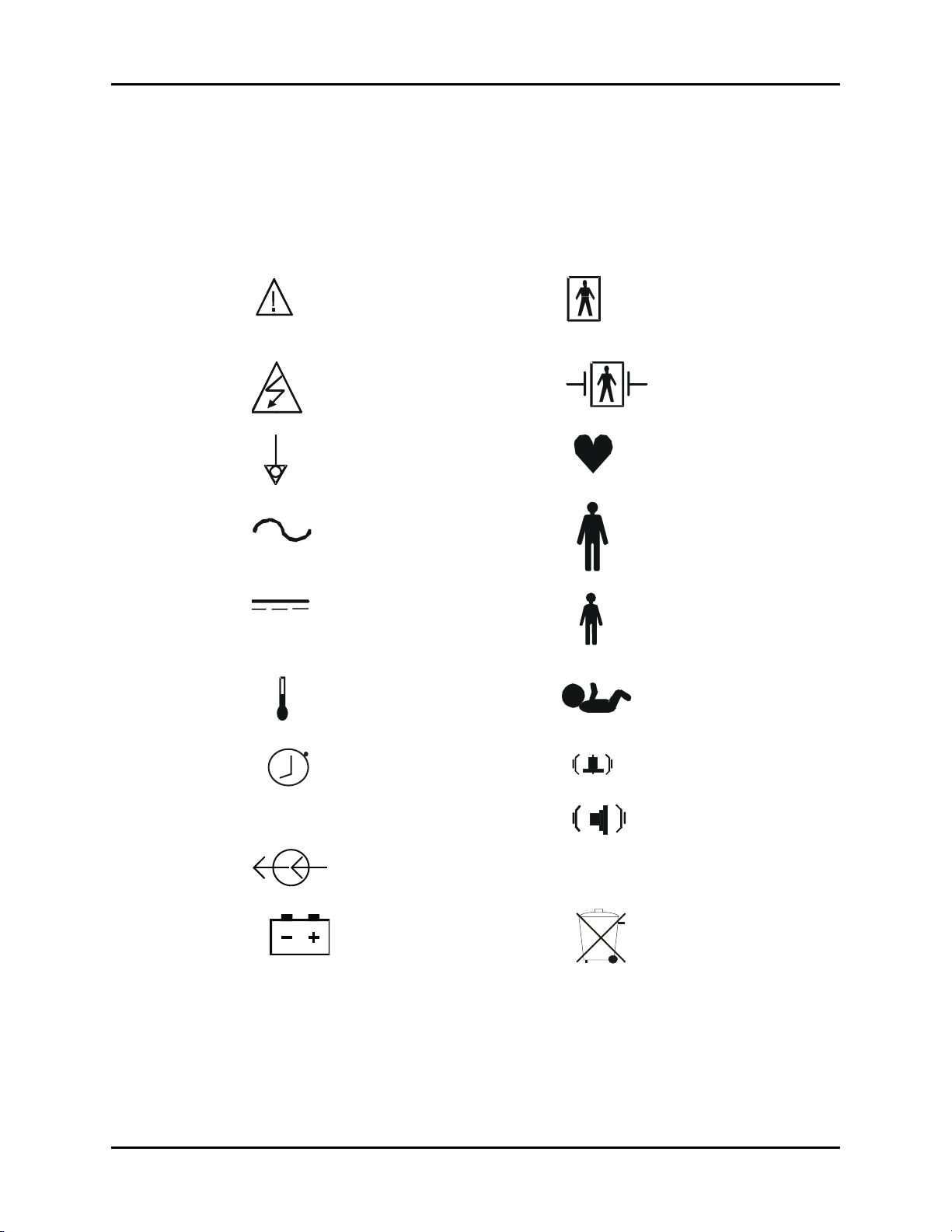
Symbols and Descriptions
Most of the symbols in the table below are defined in the IEC Publication 878 and ISO
Standard 7000. These symbols are used on all models of the Accutorr Plus.
SYMBOL DESCRIPTION SYMBOL DESCRIPTION
Attention, Consult
Accompanying Documents /
Refer to Manual
Type BF Equipment
Refer Servicing to Qualified
Service Personnel
Equipotentiality Pulse Rate
Alternating Current (AC) Adult
Direct Current (DC) Pediatric/Child
Temperature Neonate
Interval Setting / Timer Alarm Volume
Cont. Continuous NIBP Mode Beep Volume
Defibrillator-proof Type
BF Equipment
Electrical connectors Off
Battery Recycle
Accutorr Plus™ Operating Instructions 0070-10-0692-02 xiii
Page 17

Introduction Symbols and Descriptions
This page intentionally left blank.
xiv 0070-10-0692-02 Accutorr Plus™ Operating Instructions
Page 18
1.0
General Description
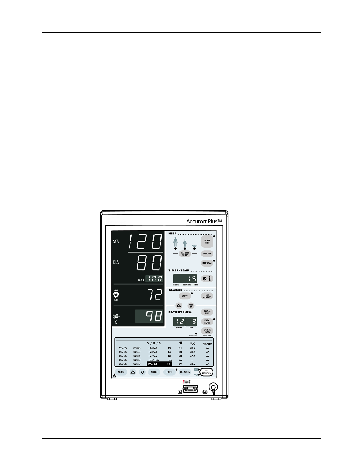
1.1 General Description
FIGURE 1-1 Accutorr Plus, advanced model (Historical Trend Display and Oximeter
optional features)
Accutorr Plus™ Operating Instructions 0070-10-0692-02 1 - 1
Page 19

General Description General Description
The Accutorr Plus is available in three models—one basic and two advanced:
1. Accutorr Plus with Lithium Ion Battery—the Accutorr Plus basic model, which
measures non-invasive blood pressure (NIBP) and Pulse Rate
2. Accutorr Plus with Nellcor® Pulse Oximetry and Lithium Ion Battery—the
Accutorr Plus advanced model, which includes basic model features, and adds Liquid
Crystal Display (LCD), Trend Screen and SpO
(Nellcor)
2
3. Accutorr Plus with Masimo SET® Pulse Oximetry and Lithium Ion
Battery—the Accutorr Plus advanced model, which includes basic model features, and
adds Liquid Crystal Display (LCD), Trend Screen and SpO
(Masimo)
2
In this manual, when a feature is described and it only refers to a particular model, it will be
noted. When the name Accutorr Plus is used, it refers to all three models.
All Accutorr Plus models are supplied with Lithium Ion Battery Technology. All models
measure NIBP and pulse rate. The Accutorr Plus features front panel digital displays for Mean
Arterial Pressures, Temperature, and Time; and extra large displays for the Systolic, Diastolic,
Pulse Rate, and SpO
. The Accutorr Plus advanced models incorporate an LCD to view
2
stored measurements (trend); to access a menu system for setting the alarm volume and SpO2
beep volume; and to display the view angle. Advanced models also add automatic SpO
measurement function with your choice of Nellcor or Masimo SpO
, depending upon your
2
2
model.
On all units, temperature can be measured with the optional Predictive Thermometer Module
(PTM) or the optional AccuTemp IR Infrared Thermometer Module. All units can also be
optionally equipped with a recorder module for documenting NIBP, pulse rate, SpO
and
2
temperature information. Each printout includes the time and date of each measurement
taken.
The Accutorr Plus can store up to 100 measurements in memory. These 100 measurements
are shared by the number of patients that are monitored by the Accutorr Plus. When only one
patient is monitored, then that one patient can have up to 100 measurements stored. When
more than one patient is monitored each patient can have any number of measurements
stored as long as the total number of stored measurements for all patients equals 100 or less.
The Accutorr Plus has an Interval Mode which enables the unit to take automatic NIBP
measurements at timed intervals.
The Accutorr Plus allows setting of alarm limits. All alarm violations are indicated by an
audible alarm tone, flashing front panel displays and brackets around the violated parameter
on the recorder print outs.
The Accutorr Plus also has the capability of operating from a battery.
1 - 2 0070-10-0692-02 Accutorr Plus™ Operating Instructions
Page 20

General Description General Description
Some key features of the Accutorr Plus are:
• Non-Invasive Blood Pressure (NIBP)
• Pulse Rate
• Nellcor or Masimo SpO
(advanced models only)
2
•Alarms
•Interval Mode
• Large Light Emitting Diode (LED) Displays
• Trend Memory - Up to 100 Measurements
• Communications - DIAP
• Nurse Call function
• Universal Power Supply
• Automatic Power Saver
• User Configured Settings
• Thermometry, PTM or AccuTemp IR (Optional)
• Recorder (Optional)
• High Contrast LCD (advanced models only)
• Customer Replaceable Lithium Ion Battery
• Universal mounting adapter for rolling stands and wall mounts
Accutorr Plus™ Operating Instructions 0070-10-0692-02 1 - 3
Page 21

General Description General Description
This page intentionally left blank.
1 - 4 0070-10-0692-02 Accutorr Plus™ Operating Instructions
Page 22

2.0
Controls and Indicators
This section of the Operating Instructions identifies and describes each control and display of
the Accutorr Plus. For step-by-step operating instructions, see Chapter 3.0, “Operation”.
The following is a list of all controls, connectors and indicators, their item number and the
page number. The item number refers to the call-outs on the drawings within this chapter. The
page number refers to the page where the description of the item can be found.
Accutorr Plus™ Operating Instructions 0070-10-0692-02 2 - 1
Page 23

Controls and Indicators
FRONT PANEL PAGE PAGE
1. NIBP SYSTOLIC DISPLAY 2-3 29. SET ALARMS KEY 2-6
2. NIBP DIASTOLIC DISPLAY 2-3 30. MUTE KEY 2-7
3. NIBP MAP DISPLAY 2-3 31. Mute Indicator 2-7
4. PULSE RATE DISPLAY 2-4 32. TIMER/TEMP KEY 2-7
5. NIBP/SpO2 Pulse Rate Indicator 2-4 33. Interval/Elap. Time/Temp Display 2-7
6. SpO2 Display (optional feature with
2-4 34. INTERVAL KEY 2-7
the Accutorr Plus advanced models)
7. LIQUID CRYSTAL DISPLAY (LCD)
2-4 35. Interval Indicator 2-7
(optional feature with the Accutorr Plus
advanced models))
8. MENU KEY (optional feature with the
2-4 36. DEFLATE KEY 2-7
Accutorr Plus advanced models)
9. LCD Up Arrow Key (optional feature
2-4 37. PATIENT SETUP KEY 2-8
with the Accutorr Plus advanced
models)
10. LCD Down Arrow Key (optional feature
2-4 38. START NIBP KEY 2-8
with the Accutorr Plus advanced
models)
11. Select Key (optional feature with the
2-4 39. Start NIBP Indicator 2-8
Accutorr Plus advanced models)
12. PRINT KEY 2-4 40. Patient Size Indicators 2-8
13. PRINT INDICATOR 2-5 REAR PANEL
14. DEFAULTS KEY 2-5 41. Thermometer Module Connector 2-12
15. SpO2 Connector (optional feature with
2-5 42. Equipotential Lug 2-9
the Accutorr Plus advanced models)
16. AC Power Indicator 2-5 43. AC Power Connector 2-9
17. Battery Indicatorr 2-5 44. Communications Connector 2-9
18. NIBP Connector 2-5 45. Service Connector 2-9
19. ON/STANDBY KEY 2-5 46. Recorder Module Connector 2-9
20. Memory Full Indicator 2-5
21. DELETE INFO. KEY 2-5 PREDICTIVE THERMOMETER MODULE (PTM)
22. DATA SCAN KEY 2-6 47. Probe Cover Holder 2-10
23. Data Scan Indicator 2-6 48. Probe Chamber 2-10
24. ROOM/BED NUMBER KEYy 2-6 49. Probe Connector 2-10
25. Bed Letter Display 2-6
26. Room Number Display 2-6 RECORDER MODULE
27. Patient Info. Down Arrow Key 2-6 50. Paper Door 2-11
28. Patient Info. Up Arrow Key 2-6 51. Paper Tear Edge 2-11
2 - 2 0070-10-0692-02 Accutorr Plus™ Operating Instructions
Page 24
Controls and Indicators Front Panel
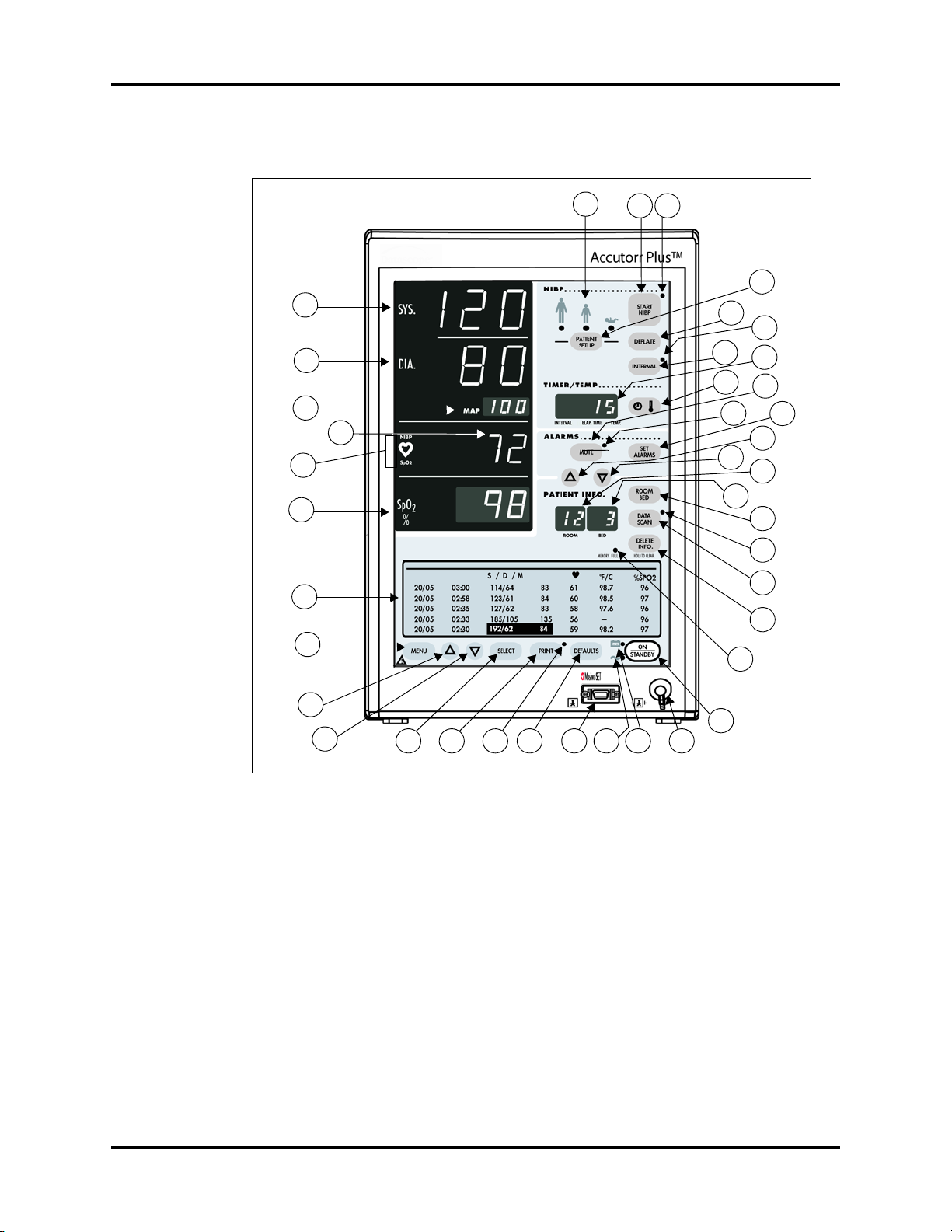
2.1 Front Panel
40
1
2
3
4
5
6
7
8
38 39
34
32
36
27
31
25
37
35
33
30
29
28
26
24
23
22
21
20
9
10
11 12 13 14 15 16 17 18
19
FIGURE 2-1 Accutorr Plus, advanced model — NIBP with Trend Screen and SpO2 with
Recorder Module (Historical Trend Display and Oximeter Optional Features)
1. NIBP SYSTOLIC DISPLAY
Displays the systolic blood pressure data from NIBP measurements. It is also used to display
NIBP error codes and systolic alarm limits.
2. NIBP DIASTOLIC DISPLAY
Displays the diastolic blood pressure data from NIBP measurements. It is also used to display
diastolic alarm limits.
3. NIBP MAP DISPLAY
Displays the mean arterial pressure (MAP) information from NIBP measurements. During a
measurement, it will display the cuff pressure. It is also used to display the MAP alarm limits
and the inflation pressure when selecting the initial inflation pressure.
Accutorr Plus™ Operating Instructions 0070-10-0692-02 2 - 3
Page 25

Front Panel Controls and Indicators
4. PULSE RATE DISPLAY
Displays the pulse rate information from either the NIBP measurement or the SpO
reading
2
(Accutorr Plus advanced model). It is also used to display pulse rate alarm limits.
5. NIBP/SpO2 PULSE RATE INDICATOR
When the pulse rate displayed is based on an NIBP measurement, then NIBP is illuminated.
When the pulse rate displayed is based on an SpO2 measurement (Accutorr Plus advanced
model), then SpO
is illuminated.
2
6. SpO
Displays the %SpO
DISPLAY (optional feature with the Accutorr Plus advanced models)
2
measurement information. This area is also used to display the %SpO2
2
alarm limits.
7. LIQUID CRYSTAL DISPLAY (LCD) (optional feature with the Accutorr Plus
advanced models)
The Liquid Crystal Display (LCD) is used to display previous measurements (trend list) for the
selected patient, or a menu that controls the beep volume and alarm volume.
8. MENU KEY (optional feature with the Accutorr Plus advanced models)
This key is used to toggle between the trend list screen and the menu screen in the LCD.
When the back light in the LCD is off, pressing this key turns it on. This key is also used to
adjust the LCD contrast. Press and hold the key for two beeps to enter the adjustment mode.
Use the Arrow keys (9 & 10) to change the contrast.
9. LCD UP ARROW KEY (optional feature with the Accutorr Plus advanced
models)
This key is used to scroll the trend data so that more recent measurements are displayed in
the LCD. When the back light in the LCD is off, pressing this key turns it on. This key is also
used to adjust the LCD contrast when in the adjustment mode. Use the Menu key (8) to enter
the adjustment mode.
10. LCD DOWN ARROW KEY (optional feature with the Accutorr Plus
advanced models)
This key is used to scroll the trend data so that older measurements are displayed in the LCD.
When the back light in the LCD is off, pressing this key turns it on. This key is also used to
adjust the LCD contrast when in the adjustment mode. Use the Menu key (8) to enter the
adjustment mode.
11. SELECT KEY (optional feature with the Accutorr Plus advanced models)
When the menu screen is displayed in the LCD, this key is used to select the menu items.
When the back light in the LCD is off, pressing this key turns it on.
12. PRINT KEY
Press this key to print all stored information for the selected patient. Press to stop a printing
that is in process. Press and hold this key (2 single beep tones, approx. 3 seconds) to change
the print mode between Continuous and Request. When in the Continuous mode, the PRINT
Indicator LED is illuminated. When loading in a new roll of recorder paper, press this key to
feed the paper through the printer.
2 - 4 0070-10-0692-02 Accutorr Plus™ Operating Instructions
Page 26

Controls and Indicators Front Panel
13. PRINT INDICATOR
This indicator is illuminated when continuous printing of measurements is selected.
14. DEFAULTS KEY
Press and hold this key (2 single beep tones, approx. 3 seconds) to reset all parameters back
to the hospital default settings. This includes alarms, inflation pressure, interval, etc. When in
the process of making a change to a setting, you can return to the original setting by
momentarily pressing this key. To enter the User Configuration, press and hold this key (1
beep tone), while turning the unit on. See section 3.15 for details on default settings and
User Configuration.
15. SpO
Connector (optional feature with the Accutorr Plus advanced
2
models)
This connector is used to attach SpO2 sensors.
16. AC Power Indicator
This green LED illuminates whenever AC power is applied to the unit.
17. Battery Indicator
This green LED illuminates whenever the unit is operating on battery power. The LED will flash
when the battery requires charging. When the LED begins flashing, at least 10 minutes
minimum of battery time remain on the Accutorr Plus.
18. NIBP Connector
This connector is used to attach specified NIBP hoses.
19. ON/STANDBY KEY
This key is used to activate the unit, enabling it to begin taking measurements. The unit does
not have to be “ON” for the internal battery to charge. However, the unit does need to be
plugged into an AC receptacle for the battery to be charging.
20. Memory Full Indicator
This LED indicator flashes when 80 - 99 of the 100 available entries of trend are used. This
LED is on continuously when 100 are used. Delete measurements manually using the DELETE
INFO. key or the unit will automatically delete the oldest measurement for the current patient.
NOTE: The unit will also automatically delete data that is 24 hours
old.
21. DELETE INFO. KEY
Press the DATA SCAN key to enable the Delete Info. key (Accutorr Plus basic model only).
Once enabled, press and hold this key (1 beep tone, approx. 3 seconds) to delete the most
recent reading when it is displayed. When displaying any measurement, press and hold this
key (2 beep tones, approx. 6 seconds) to delete all information for the currently selected
patient. Press and hold at power up to delete all information for all patients.
Accutorr Plus™ Operating Instructions 0070-10-0692-02 2 - 5
Page 27

Front Panel Controls and Indicators
22. DATA SCAN KEY
Press this key (1 beep tone) to view previous measurements for the selected patient on the
Accutorr Plus and to enable the Delete Info. key (Accutorr Plus NIBP only). The LED indicator
next to the key illuminates. On the Accutorr Plus NIBP, use the Patient Info. Up & Down Arrow
keys (27 & 28) to scroll through the stored measurements for the selected patient. On all
models of the Accutorr Plus, press and hold this key (2 beep tones, approx. 6 seconds) to
scan all of the rooms and beds for stored measurements. Press the DATA SCAN key again
to stop on a particular room/bed. Press the DATA SCAN key again to exit this view mode.
23. Data Scan Indicator
This LED indicator is illuminated when viewing prior data.
24. ROOM/BED NUMBER KEY
Press this key to change the displayed Room/Bed. After pressing this key use the Patient Info.
Up & Down Arrow keys (27 & 28) to change the Room/Bed. This key is also used when
selecting a User Configuration item.
25. Bed Letter Display
This display is used to show the current patient bed letter. It is also used to display status
codes for NIBP, SpO
and Temperature and to display User Configuration items.
2
26. Room Number Display
This display is used to show the current patient room number. It is also used to display status
codes for NIBP, SpO
and Temperature, indicates which alarm is being set (Hi or Lo), and
2
displays a User Configuration item.
27. PATIENT INFO. Down Arrow KEY
This key is used to decrement the alarm limits when they are shown on the LED displays and
to decrement the hours, minutes, month, day and year in the clock set mode. This key is also
used to change the Room/Bed, to scroll through previous data and to change initial inflation
pressure.
28. PATIENT INFO. Up Arrow KEY
This key is used to increment the alarm limits when they are shown on the LED displays and to
increment the hours, minutes, month, day and year in the clock set mode. This key is also
used to change the Room/Bed, to scroll through previous data and to change initial inflation
pressure.
29. SET ALARMS KEY
This key is used to select the NIBP and SpO
(Accutorr Plus advanced models only) alarms to
2
be changed. Repeated presses of this key sequences through the choices of Systolic Hi,
Systolic Lo, Diastolic Hi, Diastolic Lo, Map Hi, Map Lo, Pulse Rate Hi, Pulse Rate Lo, SpO
and SpO
Lo. After the last available parameter, the next press returns the unit to normal
2
2
Hi
operation. Once the desired parameter is flashing, use the Patient Info. Up & Down Arrow
keys (27 & 28) to increment or decrement the alarm values.
2 - 6 0070-10-0692-02 Accutorr Plus™ Operating Instructions
Page 28

Controls and Indicators Front Panel
30. MUTE KEY
Press this key (one beep tone), to silence the current alarm tone for 2 minutes. If a new alarm
is detected during the 2 minutes, a new alarm tone will sound. Press and hold (2 beep tones,
approx. 3 seconds) to permanently silence all alarm tones. Press this key again (1 beep
tone), to activate alarm tones.
31. Mute Indicator
This LED indicator is illuminated when the alarm tone has been silenced permanently and
when the alarm volume is set to OFF.
32. TIMER/TEMP KEY
This key is used to switch between viewing the elapsed time or the temperature in the
Interval/Elap. Time/Temp Display. When viewing stored measurements on the Accutorr Plus
NIBP, press this key to switch between viewing the temperature and time of the measurement.
33. Interval/Elap. Time/Temp Display
This displays the time, in minutes since the last successful NIBP measurement (Elap. Time is
illuminated). When the Interval key is pressed, the Elap. Time changes to the current Interval
setting (Interval is illuminated). When the Predictive thermometer probe is removed from its
holder, the Elap. Time changes to Temp (Temp is illuminated). Either “85.0" (°F) or ‘‘29.4’’
(°C) will display; this is an internal self test feature.
As the Predictive thermometer is taking a measurement, the display will flash as the number
increases. When the final temperature measurement is determined, the display will no longer
flash and a beep tone is generated. When the AccuTemp IR thermometer is used, the
temperature is not displayed until after the measurement is taken and the thermometer is
placed back into its holder. This display will also show the current time and date when setting
the clock.
34. INTERVAL KEY
Press to enter the set time interval mode. An interval is set for automatic NIBP measurement
cycles. To sequence through the interval choices of: OFF (——, when set to display graphics),
CONT (Continuous), 1, 2.5, 5, 10, 15, 20, 30, 60, 120 and 240 minutes, repeatedly press
the INTERVAL key. When the desired interval is displayed in the Interval/Elap. Time/Temp
Display the TIMER/TEMP key may be pressed to enter the interval setting or, the displayed
setting will be entered when 15 seconds have elapsed without pressing the Patient Info. Up
or Down arrow keys (27 & 28).
35. Interval Indicator
When an interval setting is selected, except for Off, the Interval Indicator flashes. When the
interval mode is activated the Interval Indicator illuminates continuously.
36. DEFLATE KEY
Press this key to stop an NIBP measurement that is in progress and deflate the cuff. A new
measurement cycle will not be allowed for 10 seconds following the use of this key. The Start
NIBP LED indicator is illuminated when a new measurement can begin. Press this key while in
the interval mode to suspend the interval operation.
Accutorr Plus™ Operating Instructions 0070-10-0692-02 2 - 7
Page 29

Front Panel Controls and Indicators
37. PATIENT SETUP KEY
Press this key (1 beep tone) to select the patient size. Each time the key is pressed the patient
size will change. The choices will cycle from Adult, Pediatric, Neonate, Adult, Pediatric,
Neonate, etc.
CAUTION: It is the user’s responsibility, when changing the room/bed,
to assure the patient size and alarm settings are set as
required.
This key is also used to view the cuff inflation pressure for an NIBP measurement. Press and
hold (2 beep tones, approx. 3 seconds) to display the current inflation pressure in the MAP
display. Use the Patient Info. Up & Down Arrow keys (27 & 28) to change the cuff pressure.
38. START NIBP KEY
Press this key to initiate an NIBP measurement. If a measurement is already in progress, a
new measurement can not be initiated until a minimum of 10 seconds after the end of the one
in progress (30 seconds when in the interval mode). The Start NIBP LED indicator is
illuminated when a measurement can begin.
39. Start NIBP Indicator
This LED indicator is illuminated when the Accutorr Plus is ready to initiate an NIBP
measurement.
40. Patient Size Indicators
One of theses LEDs illuminates to indicate the selected patient size.
2 - 8 0070-10-0692-02 Accutorr Plus™ Operating Instructions
Page 30
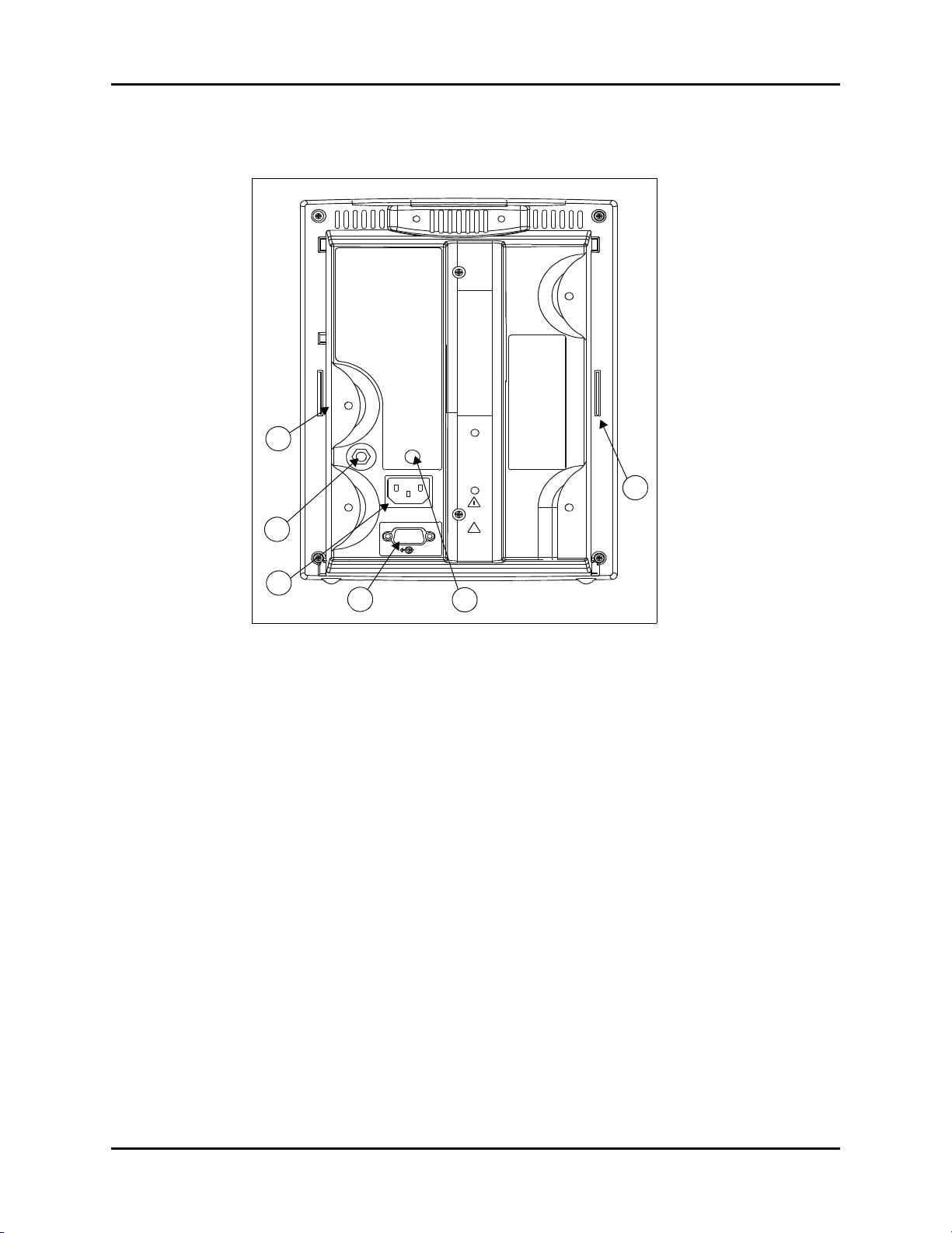
Controls and Indicators Rear Panel
2.2 Rear Panel
41
46
42
43
44
45
FIGURE 2-2 Rear Panel - All Units
41. Thermometer Module Connector
Used to attached one of the optional thermometer modules (PTM or AccuTemp IR).
42. Equipotential Lug
Provides equipotential bonding between hospital equipment.
43. AC Power Connector
Allows for A.C. power cord connection.
44. Communications Connector
Provides compatible communications to external devices and hospital’s nurse call and
information system.
CAUTION: The Communications Connector on the Accutorr Plus is only
for use with IEC 60601-1 compliant equipment.
45. Service Connector
Used by Technical Service Personnel.
46. Recorder Module Connector
Used to connect the optional recorder module.
Accutorr Plus™ Operating Instructions 0070-10-0692-02 2 - 9
Page 31

Predictive Thermometer Module (PTM) Controls and Indicators
2.3 Predictive Thermometer Module (PTM)
47
48
49
FIGURE 2-3 Predictive Thermometer Module
47. Probe Cover Holder
Used to store a box of probe covers.
48. Probe Chamber
Used to store the temperature probe when not in use.
49. Probe Connector
Used to connect the thermometer probe to the PTM module.
2 - 10 0070-10-0692-02 Accutorr Plus™ Operating Instructions
Page 32

Controls and Indicators Recorder Module
2.4 Recorder Module
50
51
FIGURE 2-4 Recorder Module
50. Paper Door
Open this door when loading recorder paper.
51. Paper Tear Edge
The paper tear edge is used to tear off printed recorder strips. The edge can be removed in
the event of a paper jam that needs to be cleared.
Accutorr Plus™ Operating Instructions 0070-10-0692-02 2 - 11
Page 33

Recorder Module Controls and Indicators
This page intentionally left blank.
2 - 12 0070-10-0692-02 Accutorr Plus™ Operating Instructions
Page 34

3.0
Operation
This section of the Operating Instructions provides guidelines and step-by-step instructions for
proper operation of the Accutorr Plus. The numbers in parentheses ( ) refer to the items
described in section 2.0, “Controls and Indicators”. When a described feature refers to a
particular model, it will be noted. When the name Accutorr Plus is used, it refers to all three
models.
3.1 Setting-up / Turning Power On
1. Before turning the power on, check the rear panel for voltage requirements. Confirm
proper voltage is available.
2. Before turning the power on, install battery and connect any required modules (recorder,
thermometer). For instructions on connecting modules, see section 3.17.
Upon installation of any optional modules, a test is required after power up (step 5). For
the recorder, press the PRINT key and the recorder will feed the paper to verify proper
function. For the Predictive thermometer, remove the probe from its holder and verify
85.0 (29.4) appears in the Interval/Elap. Time/Temp display.
3. If additional communications capabilities are required, attach a communications
interface cable to the rear panel COMMUNICATIONS CONNECTOR (44) and to the
corresponding interface connector on the peripheral instrument.
WARNING: The Communications Connector on the Accutorr Plus is only
4. Attach the AC power cord into the rear panel AC POWER CONNECTOR (43) and into
a grounded (3-prong) Hospital Grade AC receptacle. Do not use an adapter to defeat
the ground. The green AC POWER INDICATOR (16) illuminates, indicating AC power
has been applied. The internal battery charges automatically when AC power is
applied.
WARNING: When attached to other products ensure that the total
for use with IEC 60601-1 compliant equipment.
chassis leakage currents of all units (combined) do not
exceed 300µa.
Accutorr Plus™ Operating Instructions 0070-10-0692-02 3 - 1
Page 35

Setting-up / Turning Power On Operation
5. Press the ON/STANDBY key (19) to activate the unit. If it is required to enter the User
Configuration mode, press and hold the DEFAULTS key (14) while the unit is powering
on. See section 3.15 for more details on the User Configuration mode.
6. The unit will count down from 20, display all 8’s in the LEDS and perform internal
diagnostic tests. Any status codes are displayed in the appropriate LED. See section
3.16 for a list of status codes. At the end of power up, all of the displays illuminate and
then blank, except the Bed Letter and Room Number displays (25 & 26) which does not
blank. A beep tone will sound during the power up sequence to confirm the operation of
the audio indicator. If the time and date need to be set, see section 3.13 for instructions.
7. On Accutorr Plus advanced models, adjust the contrast on the LCD if necessary. To
adjust the contrast, press and hold the MENU key (8) (2 beep tones, approx. 3
seconds). Use the LCD Up & LCD Down Arrow keys (9 & 10) to adjust the contrast. See
section 3.8, Setting the LCD Contrast (View Angle Adjustment), for more details.
3 - 2 0070-10-0692-02 Accutorr Plus™ Operating Instructions
Page 36

Operation Patient Setup and Room/Bed Assignment
3.2 Patient Setup and Room/Bed Assignment
3.2.1 Selecting the Patient Size
The Patient Size is selected using the PATIENT SETUP key (37).
Adult Pediatric Neonate
PATIENT
SETUP
FIGURE 3-1 Patient Size Graphics and Indicators
1. Press the PATIENT SETUP key (37) to select the Patient size. Three choices are
available: Adult, Pediatric and Neonate. Each time the key is pressed the patient size
changes. The indicator under the graphic of the patient size illuminates to indicate which
size is selected. The factory default setting for the Patient size is Adult. See section 3.15,
“User Configuration” to set a custom default setting.
NOTE: Do not press and hold the PATIENT SETUP key to change the
patient size. Pressing and holding this key enters the initial
cuff inflation pressure change mode.
3.2.2 Cuff Inflation Pressure
The initial cuff inflation pressure depends on the Patient Size setting. The initial cuff inflation
pressures are listed in the table below. The initial cuff inflation pressures can be modified
from the default (custom or factory) settings. When the Accutorr Plus is powered down, these
modifications are deleted.
1. To modify the initial cuff inflation pressure, press and hold the PATIENT SETUP key (37)
(2 beep tones, approx. 3 seconds). The current initial cuff pressure for the selected
patient size displays in the MAP display.
2. Use the Patient Info. Up and Down Arrow keys (27 & 28) to change the pressure.
3. Once the desired pressure is displayed, press the PATIENT SETUP key (37) to enter this
value.
NOTE: Waiting 15 seconds will also enter this value.
INITIAL FACTORY
PATIENT SIZE
SETTING
Adult 180 mmHg 100 mmHg 260 mmHg 5 mmHg
Pediatric 140 mmHg 60 mmHg 160 mmHg 5 mmHg
Neonate 100 mmHg 40 mmHg 120 mmHg 5 mmHg
Accutorr Plus™ Operating Instructions 0070-10-0692-02 3 - 3
DEFAULT CUFF
INFLATION VALUES
LOWEST
SELECTABLE
PRESSURE
HIGHEST
SELECTABLE
PRESSURE INCREMENT
Page 37

Patient Setup and Room/Bed Assignment Operation
NOTE: The default patient size and initial cuff inflation pressure can
be customized. See section 3.15, “User Configuration” for
Room Number and Bed Letter
3.2.3 Room Number and Bed Letter
To monitor more than one patient, assign each patient to a particular room number and bed
letter. Use the ROOM/BED key (24) to set the room number from 0 to 99 and the bed letter
as a, b, c or d. On initial power up (no stored patient data), the room number and bed letter
default to 0,a.
PATIENT I NFO.
ROOM BED
MEMORY FULL
FIGURE 3-2 Room Number and Bed Letter Keys and Indicators
ROOM
BED
DATA
SCAN
DELETE
INFO.
HOLD TO CLEAR.
Press to increase or
decrease the Room
Number and Bed Letter
Press to change the
Room Number and
Bed Letter
1. Press the ROOM/BED key (24). The ROOM LED flashes indicating that the room
number can now be changed.
2. Press the PATIENT INFO. Up or Down Arrow key (27 & 28) to increment or
decrement the room number.
3. Press the ROOM/BED key again. The BED LED flashes.
4. Press the PATIENT INFO. Up or Down Arrow key (27 & 28) to increment or
decrement the bed letter.
5. Press the ROOM/BED key a third time to exit this mode, or do not press the key for 15
seconds.
Once measurements have been taken, and the unit is powered off and on, the room number
and bed letter will default to the lowest room and bed where data is currently stored.
3 - 4 0070-10-0692-02 Accutorr Plus™ Operating Instructions
Page 38

Operation Manual NIBP Measurements and General NIBP Measurement Information
3.3 Manual NIBP Measurements and General NIBP Measurement Information
1. Select a pressure cuff that is appropriate for the size of the patient. Use the chart below
as a guideline.
LIMB CIRCUMFERENCE (CM)
DISPOSABLE CUFFS - QUICK CONNECT - LATEX FREE
10 - 19 Small Child 0683-14-0001-01
18 - 26 Small Adult 0683-14-0002-01
25 - 35 Adult 0683-14-0003-01
33 - 47 Large Adult 0683-14-0004-01
46 - 66 Adult Thigh 0683-14-0005-01
25 - 35 Adult Long 0683-14-0006-01
33 - 47 Large Adult Long 0683-14-0007-01
3 - 6 Neonatal, Size 1 0683-
5 - 8 Neonatal, Size 2 0683-
7 - 10 Neonatal, Size 3 0683-
9 - 13 Neonatal, Size 4 0683-
12 - 17 Neonatal, Size 5 0683-
REUSABLE CUFFS** - QUICK CONNECT - LATEX FREE
10 - 19 Small Child 0683-15-0001-01
18 - 26 Small Adult 0683-15-0002-01
25 - 35 Adult 0683-15-0003-01
33 - 47 Large Adult 0683-15-0004-01
46 - 66 Adult Thigh 0683-15-0005-01
25 - 35 Adult Long 0683-15-0006-01
33 - 47 Large Adult Long 0683-15-0007-01
* When using the thigh cuff, this product may not comply with product specifications listed in chapter 6.
** The limb circumferences of cuffs adhere to the AHA guidelines for size. They also incorporate index and
range lines to assist in cuff selection.
DESCRIPTION /
CUFF NAME PART NUMBER
23-0001-01
23-0002-01
23-0003-01
23-0004-01
23-0005-01
A cuff that is too small for the limb will result in erroneously high readings. The correct size of
the pressure cuff for a given patient has, among other considerations, a direct bearing on the
accuracy of the obtained NIBP measurements. Base your selection of the cuff size on the limb
circumference of the patient. The table above indicates the available cuffs for use with the
Accutorr Plus. The design dimensions of the cuffs and their intended uses are based on
recommendations of the American Heart Association.
NOTE: The cuffs that are used with the Accutorr Plus use special
snap on connectors.
WARNING: Use only authorized accessories. Use of unauthorized
accessories may result in erroneous measurements.
Accutorr Plus™ Operating Instructions 0070-10-0692-02 3 - 5
Page 39

Manual NIBP Measurements and General NIBP Measurement Information Operation
The pressure on the limb may not fall to zero between measurements if the cuff is wrapped
too tightly. Therefore, assure that the cuff is properly applied.
The skin is sometimes fragile (i.e., on pediatrics, geriatrics, etc.). In these cases, a longer
timer interval should be considered to decrease the number of cuff inflations over a period of
time.
NOTE: In extreme cases, a thin layer of soft roll or webril cotton
padding may be applied to the limb in order to cushion the
skin when the cuff is inflated. This measure may affect NIBP
performance and should be used with caution.
2. Attach the cuff hose to the NIBP cuff connector (18). To do this, hold the hose behind the
knurled pressure fitting (female). Push onto the male connector until a click is heard. To
remove, hold the knurled female fitting and pull firmly to release.
3. Apply the cuff to the patient. To reduce errors, the cuff should fit snugly, but with enough
room for two fingers to be placed between the cuff and the patient’s arm (on adults), and
with little or no air present within the cuff. Cuff should fit loosely on neonates. Apply the
cuff so that the center of the inflation bag (bladder) is over the brachial artery. Be sure
that the INDEX line on the cuff falls between the two RANGE lines. If not, a larger or
smaller cuff is required. Be sure the cuff lies directly against the patient’s skin. For best
results, the cuff should be placed on the arm at heart level and no clothing should come
between the patient and the cuff.
NOTE: Avoid compression or restriction of the pressure hose. The
NIBP cuff should not be placed on a limb that is being
utilized for any other medical procedure. For example, an
I.V. Catheter.
4. If required, select the patient size with the PATIENT SETUP key (37). On initial power up,
the configurable default setting is used. Otherwise, the last selected patient size is used.
Initial default cuff inflation pressures depend on the Patient Size setting. See section
3.2.2 for details on changing the initial cuff inflation pressure.
5. Press the START NIBP key (38) to begin an NIBP measurement. A beep is sounded
after a completed measurement.
NOTE: Inflate the cuff only after proper application to the patient’s
limb. Cuff damage can result if the cuff is left unwrapped
and then inflated.
The cuff begins to inflate to the selected cuff pressure. After reaching the selected pressure,
the cuff begins to slowly deflate and the Accutorr Plus collects oscillometric pulsations.
If the initial cuff inflation is found to be inadequate, the unit retries with a higher inflation
pressure (+50 mmHg in the adult mode; +50 in the pediatric mode; +40 mmHg in the
neonate mode). A triple beep tone is generated.
NOTE: Any time there is an unsuccessful NIBP measurement, a
triple beep tone is generated.
Have the patient remain still to avoid unnecessary motion artifact. After the cuff pressure
drops below the diastolic pressure, the results of the measurement are displayed and the cuff
is vented to atmosphere.
3 - 6 0070-10-0692-02 Accutorr Plus™ Operating Instructions
Page 40

Operation Manual NIBP Measurements and General NIBP Measurement Information
If an error code displays in the Systolic Display or a status code in the Room/Bed Display,
refer to Section 3.16, Status and Error Codes, for its explanation. A successful measurement
clears a status code. To clear a status code, press the ROOM/BED NUMBER key (24).
6. When required, press the DEFLATE key (36) to interrupt a measurement. The cuff will
deflate.
NOTE: Once the initial measurement is taken for a room/bed, the
Accutorr Plus will continue to use the selected patient size.
NOTE: Check the patient’s limb for any indications of circulation
impairment.
3.3.1 NIBP Pressure Limit Fail Safe
If the cuff is over-pressurized, it will automatically deflate and the status code 8812 (STOP CUFF OVER PRESSURE) or error code 987 (STOP - HARDWARE OVER PRESSURE) will be
displayed in the Room/Bed or systolic display.
The unit must be turned off and back on again to reset the hardware over-pressure switch
(error code 987) before any new measurements can be taken.
3.3.2 Cuff Inflation Time
If the cuff pressure does not attain 20 mmHg within 40 seconds of the start of inflation or if
the target pressure is not reached within another 60 seconds, then the cuff is deflated and
status codes will be displayed in the Room/Bed display. See section 3.16 for a list of error
and status codes.
3.3.3 Automatic Adjustment of Cuff Inflation Pressure (Adaptive Inflation)
The unit adjusts the inflation pressure according to the previous reading of the systolic
pressure. After the first successful measurement, the inflation pressure is the previous systolic
+50 mmHg in the adult mode, +50 mmHg in the pediatric mode and +40 mmHg in the
neonate mode. When not in Interval mode the Adaptive inflation may be disabled.
To view the current inflation pressure, press and hold (2 beep tones, approximately 3
seconds) the Patient Setup Key (37). The current inflation pressure is shown in the MAP
display. If required, use the Patient Info. Up & Down arrow keys (27 & 28) to change the
inflation pressure. It is also possible to permanently override this adjustment in the User
Configuration. See section 3.15 for details.
Accutorr Plus™ Operating Instructions 0070-10-0692-02 3 - 7
Page 41

Automatic NIBP Measurements (Interval Mode) Operation
3.4 Automatic NIBP Measurements (Interval Mode)
The Accutorr Plus can be set to automatically take NIBP measurements. On initial power up,
the interval setting will default to OFF. The User Configuration mode can be used to set
custom defaults for the Interval Mode. See section 3.15, User Configuration for details. In this
mode, the adaptive inflation is always enabled.
Follow Steps 1 - 4 in the Manual Procedure, section 3.3, to select, attach and apply the cuff
and to adjust the initial cuff inflation pressure.
5. Press the INTERVAL key (34). The current selection is displayed in the Interval/
Elap.Time/Temp. display (33). Press the INTERVAL key to scroll to the next available
interval selection. The selections are: Off (—— when set to graphic display), CONT
(continuous), 1, 2.5, 5, 10, 15, 20, 30, 60, 120 and 240 minutes. When an interval
setting is selected, except for Off, the Interval Indicator (35) flashes. When the interval
mode is activated the Interval Indicator illuminates continuously.
6. The displayed interval time is entered when the INTERVAL key has not been pressed for
15 seconds or, when the TIMER/TEMP key (32) is pressed, which changes the display
back to Elap. Time or, when the START NIBP key (38) is pressed, which initiates an NIBP
measurement, activates the Interval Mode, and changes the display back to Elap. Time.
7. If the START NIBP key (38) has not already been pressed, press to take a measurement
and to activate the interval mode.
NOTE: If the interval time is changed, the START NIBP key does not
need to be pressed for the new interval to initiate. When the
new time interval has elapsed, a measurement will be
taken.
NOTE: When the NIBP continuous interval is chosen, the Accutorr
Plus will take back to back (one right after the other) blood
pressure readings. As a safety precaution, a five minute
limit is placed on continuous measurements. After 5
minutes, the NIBP interval will automatically switch to
measurements taken once every 5 minutes. This is done to
reduce the chance of surface vessel rupture (petechia).
If it is desirable to maintain a fixed cuff inflation pressure, the adaptive inflation feature may
be disabled when not in Interval mode.
3.4.1 Canceling an Automatic NIBP Measurement
To cancel a scheduled measurement, press the DEFLATE key (36). This will suspend the
timed NIBP measurements until the START NIBP key (38) is pressed. The interval indicator will
flash. See section 3.4.4 for more details on the start and deflate function.
NOTE: Pressing the DEFLATE key (36) will also end a measurement
cycle that is already in progress.
To take an immediate measurement and to reactivate the Interval mode, press the START
NIBP key (38). The next timed measurement will be taken at the time set by the interval. For
example, if the interval was set to 30 minutes, the next timed measurement will be 30
minutes after the START NIBP key was pressed.
3 - 8 0070-10-0692-02 Accutorr Plus™ Operating Instructions
Page 42

Operation Automatic NIBP Measurements (Interval Mode)
NOTE: If the Interval mode is no longer required, set the interval to
NOTE: If the DEFLATE key (36) is pressed, it will take 10 seconds
NOTE: When in the Interval mode and the Room/Bed is changed,
“OFF” prior to pressing the START NIBP key. See section 3.4
for details on changing the interval mode.
before another measurement can be taken. The START NIBP
INDICATOR (39) will be illuminated, when ready.
the interval mode is suspended (interval indicator flashes)
until the NIBP Start key is pressed.
3.4.2 Changing the Interval Setting
If the interval time is changed while the Accutorr Plus is in the interval mode, the new interval
time is used once it is entered. For example: The interval time is set to 60 minutes. Thirty
minutes have elapsed since the last timed automatic measurement and the interval time is
changed to 10 minutes. Once the interval time is entered, the Accutorr Plus will take an
automatic NIBP measurement in 10 minutes and then once every 10 minutes.
3.4.3 Effects of Changing the Room Number and/or Bed Letter on the Interval Setting
When the Room Number and/or Bed Letter is changed, the interval setting will remain the
same.
NOTE: The interval setting can be changed if required. Also, if an
NIBP measurement is in progress, the measurement will
stop and the cuff will deflate. The timed interval
measurements will not activate again (interval indicator
flashes) until the START NIBP key (38) is pressed.
3.4.4 START and DEFLATE Functions
The START NIBP and DEFLATE functions have the following effects on the timed measurement
sequence.
INTERVAL mode is active and the START NIBP key (38) is pressed causing an unscheduled
measurement to be taken. Taking this unscheduled measurement does not affect the timing of
the interval cycle, therefore, the scheduled measurements will still be taken as if there were
no interruptions. Only one measurement is taken for each measurement cycle - even if the
unscheduled measurement coincides with the scheduled measurement.
INTERVAL mode is active and the DEFLATE key (36) is pressed. The INTERVAL INDICATOR
(35) flashes. No additional measurements will be taken until the START NIBP key (38) is
pressed. If a timed measurement is in progress, the measurement is suspended and the cuff
deflates.
INTERVAL mode is active and the interval time is changed. The measurement cycle is reset
with the new interval. A measurement will be taken after the new interval time has elapsed.
Accutorr Plus™ Operating Instructions 0070-10-0692-02 3 - 9
Page 43

Alarms Operation
_ _
_ _ _
_
_
3.5 Alarms
The Accutorr Plus provides “HI” and “LO” alarm limit settings for systolic, diastolic, MAP,
pulse rate and SpO
or falls outside the limits that have been specified.
WARNING: Removing the battery from the Accutorr Plus while the AC
3.5.1 Setting Alarm Limits
The Factory Default for all parameter alarms, except Low SpO2, is OFF. The Low SpO2
factory default is 86. The User Configuration mode can be used to set custom defaults. See
section 3.15, User Configuration for details. The factory and custom defaults for alarms can
be changed as required to accommodate the needs of individual patients. The SET ALARMS
key (29) and the Patient Info. Up and Down Arrow keys (27 & 28) are used to set alarm
values.
1. Press the SET ALARMS key (29) (1 beep) to enter into the alarm set mode.
. An alarm violation occurs when one or more patient parameters equals
2
line cord is disconnected may cause the alarm settings to be
reset to their defaults.
The first time this key is pressed, all NIBP displays blank except for the systolic display
which shows the current high systolic alarm value. The word HI is displayed in the
Interval/Elap. Time/Temp display (33).
The second time the SET ALARMS key (29) is pressed the Systolic LO parameter is
selected. The word LO is displayed in the Interval/Elap. Time/Temp display (33). When
the unit has been configured to display graphics, the symbol is displayed.
_ _ _ _
_ _ _ _
_ _ _ _
_
_ _ _ _
_ _ _ _
_ _ _ _
_
_
_ _ _
_ _ _ _
_ _ _
_ _ _ _
When the graphic is displayed, the bottom lines blink. This indicates the low alarm is
selected.
Each time the SET ALARMS key (29) is pressed a new parameter is selected for alarm
setting (all other displays blank). The order they are available is: Systolic HI, Systolic LO,
Diastolic HI, Diastolic LO, MAP HI, MAP LO, Pulse Rate HI, and Pulse Rate LO, SpO
2
HI
and SpO2 LO. When all of the available parameters have been selected, the next press
of the ALARM SELECT key returns the Accutorr Plus to normal operation.
2. To change an alarm limit setting, use the Patient Info. Up & Down Arrow keys (27 & 28).
The Up arrow increments the alarm limit setting. The Down arrow decrements the alarm
limit setting.
To cancel all of the changed alarm values while still in progress of changing, press the
DEFAULTS key (14) (1 beep tone).
If the SET ALARMS or Arrow keys have not been pressed for 15 seconds, the Accutorr
Plus returns to normal operation and saves any alarm limit changes.
NOTE: If the patient size is changed, the alarm settings will change
to the default settings for the new patient size.
3 - 10 0070-10-0692-02 Accutorr Plus™ Operating Instructions
Page 44

Operation Alarms
Alarm Limit Table
PAR AMETE R RANGE UNITS
Systolic High
Adult
Pediatric
Neonate
Off, 60-260
Off, 60-160
Off, 50-125
mmHg Off 5
Systolic Low
Adult
Pediatric
Neonate
Off, 55-150
Off, 55-130
Off, 45-115
mmHg Off 5
Diastolic High
Adult
Pediatric
Neonate
Off, 40-200
Off, 40-150
Off, 35-100
mmHg Off 5
Diastolic Low
Adult
Pediatric
Neonate
Off, 30-120
Off, 30-50
Off, 25-50
mmHg Off 5
MAP High
Adult
Pediatric
Neonate
Off, 90-200
Off, 90-150
Off, 60-110
mmHg Off 5
MAP Low
Adult
Pediatric
Neonate
Off, 40-100
Off, 40-70
Off, 30-70
mmHg Off 5
Pulse Rate High
Adult
Pediatric
Neonate
Off, 100-245
Off, 100-245
Off, 100-245
bpm Off 5
Pulse Rate Low
Adult
Pediatric
Neonate
High
SpO
2
Adult
Pediatric
Neonate
SpO
Low
2
Adult
Pediatric
Neonate
Off, 35-120
Off, 35-150
Off, 75-200
Off, 61-99
Off, 61-99
Off, 61-99
60-95
60-95
60-95
bpm Off 5
%SpO
%SpO
FACTORY
DEFAULT
2
2
Off 1
86 1
UNITS OF
INCREMENT
Accutorr Plus™ Operating Instructions 0070-10-0692-02 3 - 11
Page 45

Alarms Operation
3.5.2 Alarm Violations
An alarm condition exists if the physiological parameter is equal to or is outside the high/low
limit range that has been set. When an alarm limit is violated, the following actions occur:
• The LEDs for the parameter in an alarm condition flashes.
• The parameter in an alarm condition is in reverse video on the LCD (Accutorr Plus
advanced models).
• The alarm tone is sounded (unless muted with the MUTE key (30)).
• The parameter(s) that was in an alarm condition will be in brackets [ ] when printed on
the recorder.
3.5.3 How to Mute Alarms
When an NIBP alarm exists, press the MUTE key (30) (1 beep tone) to silence the alarm tone
for 2 minutes. The alarm tone will return after the next measurement value that violates the
selected limits.
When an SpO
tone for two minutes. The alarm tone will return after two minutes, unless the SpO2 value
changes and is within the alarm limits. If during that two minutes the measured SpO
changes to a value that is within the acceptable range, and then returns to a value that is
outside the set alarm limit, the alarm tone will return before the two minutes elapse. Example
(within 2 minutes): • SpO
the alarm tone sounds and the SpO
measured at 88; there is no alarm tone, but the SpO2 display flashes. • SpO2 is measured at
91; no alarm tone sounds and the display stops flashing. • SpO
alarm tone sounds and the SpO
Press and hold the MUTE key (30) (2 beep tones, approx. 3 seconds) to permanently silence
the alarm tone. The MUTE LED (31) illuminated. The LEDs for the alarming parameter will
continue to flash. To reactivate the alarm tone function, press the MUTE key (30) again.
alarm exists, press the MUTE key (30) (1 beep tone) to silence the alarm
2
low alarm limit has been set to 90. • SpO2 is measured at 89;
2
display flashes. • The MUTE key is pressed. • SpO2 is
2
is measured at 89; the
2
display flashes.
2
3.5.4 Alarms and Changing the Room Number and/or Bed Letter
When changing the rooms and beds, the alarm settings will change if the final room/bed
displayed is a different patient size than the original room/bed. When a new patient size is
detected, the alarm settings change to the defaults for the different patient size. See section
3.15 for information on custom defaults.
The table below describes 6 measurements in different rooms/beds and different patient
sizes, and the effect on the alarm settings.
value
2
3 - 12 0070-10-0692-02 Accutorr Plus™ Operating Instructions
Page 46

Operation Alarms
MEASUREMENT
ORDER
1 1/a Adult Have been manually set.
2 1/b Adult Remain the same.
3 2/a Pediatric Changed to defaults for a pediatric size
4 3/a Adult Changed to defaults for an adult size patient.
5 4/a Adult Remain the same.
6 1/a Adult Remain the same. If the alarm settings that
NOTE: The alarm settings can be changed, if necessary, when
changing the room/bed and the patient size is the same.
CAUTION: It is the user’s responsibility, when changing the room/bed,
to assure the patient size and alarm settings are set as
required.
ROOM/
BED
PATIENT
SIZE ALARM SETTINGS
patient.
were set from the 1st measurement are
required, they need to be set again manually.
Accutorr Plus™ Operating Instructions 0070-10-0692-02 3 - 13
Page 47

To View and Delete Stored Data (Trend Mode) Operation
3.6 To View and Delete Stored Data (Trend Mode)
The Accutorr Plus is capable of storing up to 100 entries of measurement data. Each time a
successful NIBP measurement is made, the data is automatically stored in memory. When a
temperature measurement is made between two minutes before and two minutes after an
NIBP measurement, it is stored as the same entry with the NIBP measurement. If a
temperature measurement is made outside this time, it is stored as a separate entry. When
either NIBP or temperature measurements are stored and SpO
the SpO
When 80 to 99 entries are stored into trend memory, the MEMORY FULL Indicator (20) will
flash. When 100 entries are stored into trend memory, the MEMORY FULL Indicator (20) will
illuminate continuously. Once 100 entries are stored, old data can be deleted manually for
any patient; or when new data is available, the Accutorr Plus will automatically delete the
oldest data for the currently displayed patient.
data is also stored.
2
information is available, then
2
NOTE: The unit will also automatically delete data that is 24 hours
The Accutorr Plus basic model uses the Systolic, Diastolic, MAP, and Temp displays to view
stored data. The Accutorr Plus advanced models display up to 5 measurements at a time. The
stored data that is viewed is for the currently selected patient (indicated by the room number/
bed letter).
old.
3.6.1 To View the Stored Measurements on the Accutorr Plus, basic model
1. Press the DATA SCAN key (22) (1 beep tone). The DATA SCAN Indicator (23)
illuminates.
2. Press the PATIENT INFO. Up and Down Arrow keys (27 & 28) to view stored data
for the current patient. The stored data is displayed in the Systolic, Diastolic, MAP, Pulse
Rate and Temp displays.
Consecutive presses or pressing and holding the UP or DOWN arrow will allow the
stored measurements to continuously wrap around. When the measurements wrap, a
double beep tone will sound. If a temperature measurement is not available for the NIBP
measurement that is displayed, then - - - - is shown in the Interval/Elap. Time/Temp
display (33). To view the time of measurements, press the TIME/TEMP key (32).
3. To exit the view stored data mode, press the DATA SCAN key (22) (1 beep).
3.6.2 To View the Stored Measurements on the Accutorr Plus, advanced models
The stored measurements on the Accutorr Plus advanced models are displayed in the LCD.
Up to 5 stored measurements are displayed at one time. Measurements are displayed in time
order, with the newest measurement at the top. A scroll bar with one or both arrows will
display on the right side of the LCD when more measurements are available to view. When
only one arrow displays, more measurements are only available in the direction of the arrow.
3 - 14 0070-10-0692-02 Accutorr Plus™ Operating Instructions
Page 48

Operation To View and Delete Stored Data (Trend Mode)
1. To view more measurements press the LCD Up or Down Arrow key (9 & 10).
TimeDate
o
F/C
S / D / M
20/05
20/05
20/05
20/05
20/05
FIGURE 3-3 LCD Trend List Display
03:00
02:58
02:35
02:33
02:30
114/64
123/61
127/62
185/105
129/62
Alarm Violated Measurement
83
84
83
135
84
61
60
58
56
59
98.7
98.5
97.6
----
98.2
%SPO2
96
97
96
96
97
3.6.3 To Delete the Stored Measurements on the Accutorr Plus
While viewing stored data, you can delete the most recent measurement or all of the stored
measurements for the currently displayed patient.
1. Select a room/bed where stored information can be deleted. (See section 3.2.3 for
details on selecting a room/bed.) If it is the currently displayed room/bed, go to step 2.
When you are uncertain what rooms/beds have stored data, press and hold the DATA
SCAN key (22) (2 beep tones, more than 3 seconds). The Accutorr Plus will scan
through all of the rooms/beds that have data stored. To stop on a Room/ Bed as the
Accutorr Plus is scanning, press the DATA SCAN key (22).
NOTE: The Accutorr Plus will scan through the rooms/bed with
stored data only once.
Scroll
Bar
2. On the Accutorr Plus NIBP only, when the desired room/bed is displayed, press the
DATA SCAN key (22) (1 beep tone). The DATA SCAN Indicator (23) illuminates.
3. When the most recent stored data is displayed, press and hold the DELETE INFO. key
(21) (1 beep tone, approx. 3 seconds) to delete this measurement.
4. When viewing any of the stored measurements, press and hold the DELETE INFO. key
(21) (2 beep tones, approx. 6 seconds) to delete all stored measurements for the current
patient. When all data is cleared the patient size will be the default selection.
5. On the Accutorr Plus NIBP only, press the DATA SCAN key (22) (1 beep tone) to exit
the delete data mode.
NOTE: The unit will also automatically delete data that is 24 hours
old.
NOTE: To delete all information for all patients, press and hold the
DELETE INFO. key (21) while powering on the unit.
Accutorr Plus™ Operating Instructions 0070-10-0692-02 3 - 15
Page 49

Setting the Alarm Volume and Beep Volume Operation
3.7 Setting the Alarm Volume and Beep Volume
The LCD on the Accutorr Plus advanced models is used to display the Trend List as described
in section 3.6. It is also used to display a menu which is used to set the alarm volume and the
SpO
beep volume. The MENU key (8), the LCD Up and Down Arrow keys (9 & 10), and the
2
SELECT key (11) are used to set these volumes. The User Configuration mode can be used to
set custom defaults for the alarm volume and beep volume. See section 3.15, User
Configuration for details.
1. Press the MENU key (8) to display the menu. The menu is shown in figure 3-4. The
alarm volume is initially highlighted when the menu is displayed. The highlighting
indicates this item can be changed.
2. Press the LCD Up and Down Arrow keys (9 & 10) to change the current selection for
the alarm volume. The selections are: OFF, 1, 2, 3, 4, and 5 with 5 being the loudest.
3. Press the SELECT key (11) to move the highlighting to SpO2 beep volume.
4. Press the LCD Up and Down Arrow keys (9 & 10) to change the current selection for
the SpO2 volume. The selections are: OFF, 1, 2, 3, 4, and 5 with 5 being the loudest.
5. Press the MENU key (8) again to exit the menu and return to the Trend screen.
NOTE: Any changes made to the alarm volume or the SpO2
volume will be erased when the unit is turned off and then
back on again. Also, any changes made (except off) will
restore and enable the alarm tone, regardless of prior mute
condition.
Alarm
Vol um e
SpO2 Beep
Vol um e
3
3
FIGURE 3-4 Menu
3 - 16 0070-10-0692-02 Accutorr Plus™ Operating Instructions
Page 50

Operation Setting the LCD Contrast (View Angle Adjustment)
3.8 Setting the LCD Contrast (View Angle Adjustment)
The LCD on the Accutorr Plus advanced models can be adjusted for optimum viewing. The
MENU key (8) and the LCD Up and Down Arrow keys (9 & 10) are used to adjust the
contrast.
1. Press and hold the MENU key (8) (2 beep tones, approx. 3 seconds). A beep tone is
generated when the key is first pressed and the display changes to the menu. When a
second beep tone is generated, release the key.
2. To quickly adjust the contrast, press and hold either the LCD Up or Down Arrow key
(9 or 10). For fine adjustment, momentarily press either the LCD Up or Down Arrow
key.
3. The LCD contrast adjustment is saved by either pressing the MENU key (8) again or not
pressing either the LCD Up or Down Arrow keys (9 & 10) for 15 seconds.
NOTE: The contrast setting will be the same each time the unit is
turned on, unless readjusted by the user.
3.9 Display Time Out Mode
To conserve power, most displays will blank at user selected times. The LCD illumination time
out can be set between 3 and 15 minutes. The LED display time out can be set between 5
and 60 minutes. Since the Accutorr Plus can be powered from either an AC or DC source,
the user configuration allows the setting of separate times for each type of power source. See
User Configuration, section 3.15 for more information on setting the time out minutes.
To turn on the LCD light, press the MENU key (8). To turn on the LED displays, press any key.
Accutorr Plus™ Operating Instructions 0070-10-0692-02 3 - 17
Page 51

SpO2 Measurements (Accutorr Plus advanced models) Operation
3.10 SpO2 Measurements (Accutorr Plus advanced models)
To obtain SpO2 measurements and SpO2 Heart Rate from the Accutorr Plus advanced
models, see section 3.10.2 for units with Nellcor SpO2, and section 3.10.3 for units with
Masimo SpO
CAUTION: Do not place the sensor on an extremity with an invasive
CAUTION: A pulse oximeter should not be used as an apnea monitor.
CAUTION: A pulse oximeter should be considered an early warning
CAUTION: Ensure proper routing of the patient cable to avoid
.
2
catheter or blood pressure cuff in place.
device. As a trend towards patient deoxygenation is
indicated, blood samples should be analyzed by a
laboratory co-oximeter to completely understand the
patient’s condition.
entanglement and/or strangulation.
NOTE: In the event you are unable to obtain a reading, or the
reading is inaccurate, check the patients vital signs by
alternate means and consider the following:
• If your patient is poorly perfused, try applying the sensor to another
site (i.e. a different finger or toe).
• Check that the sensor is properly aligned.
• In electrosurgery, make sure the sensor is not too close to ESU
devices or cables.
• Check to make sure the site area is clean / non-greasy. Clean the site
and sensor if needed. Nail polish and fungus should be removed.
3.10.1 Pulse Oximetry Sensors
A. Sensor Selection and Application
Selection of a specific sensor is based on the patient’s size, physical condition, and expected
monitoring duration. Instructions for the application of a sensor to a patient are provided in
each sensor package. For optimal placement, ensure that cable side is placed in the correct
position see FIGURE 3-5 and FIGURE 3-6).
Cable on Top
Cable on Bottom
FIGURE 3-5 Typical reusable sensor
placement
FIGURE 3-6 Typical flexible sensor
placement
B. Sensor Connection to the Accutorr Plus advanced model:
3 - 18 0070-10-0692-02 Accutorr Plus™ Operating Instructions
Page 52

Operation SpO2 Measurements (Accutorr Plus advanced models)
1. Align the cable connector on the sensor assembly with the SpO2 Connector (15) on the
Accutorr Plus advanced model.
2. Push the cable connector into the SpO2 Connector (15). Confirm that the cable
connector is securely in place.
3. The digital SpO
values and SpO2 pulse rate will be displayed in the SpO2 and pulse
2
Rate LED windows.
4. If desired, adjust the beep volume. See section 3.7, Setting the Alarm Volume and Beep
Volume, for details on adjusting the beep volume.
C. Sensor Inspection
Before use, always inspect sensors, cables, and connectors for damage, i.e., cuts and
abrasions. Do not use the sensor, cable or connector if damaged. Replace with a good
working sensor.
For long sensor life:
• Do not drop on the floor, or give other sharp shocks to the sensor(s). Between use, store
the sensors in the accessory pouch, or coil the sensor cable and store on the side of the
Accutorr Plus rolling stand using the optional cable retainer. For accessory part number
information see section 5.0, “Accutorr Plus Versions and Accessories”.
• Avoid running any cart, bed, or any piece of equipment over the sensor cable.
• Avoid strong pulls on the sensor cable (10 lbs/4kg).
• Watch for cracks in the housing.
• Watch for cracks, cuts, rips, fogging, or signs of moisture accumulation.
D. Sensor Performance
For the BEST performance:
• DO NOT PLACE any sensor on an extremity with an arterial catheter or blood pressure
cuff in place. Placement of an arterial catheter or blood pressure cuff on an extremity may
obstruct normal blood flow. False pulse rate information may result if the sensor is placed
on that same extremity. Place the sensor on the limb opposite the site of the arterial
catheter or blood pressure cuff.
• Encourage the patient to remain still. Patient motion may affect the sensor’s performance.
If it is not possible for the patient to remain still, replace the sensor bandage on the sensor
to assure good adhesion, or change the site of the sensor.
• Check the reusable sensor site every 2 hours and check the disposable sensor site every
8 hours for indications of skin abrasions, sensor displacement, sensor damage, or
circulation impairment. Check the sensor site every 4 hours if the ear clip is used. If
necessary, remove and reapply the sensor. If any of the above mentioned indications
occur, immediately remove the sensor and find an alternate site. NOTE: Check the sensor
site more frequently on infant and active patients.
• Incorrect placement can also reduce the acquired sensor signal, and therefore
compromise performance. Select an alternate site (toe) if the sensor can not be placed on
the patient’s finger correctly or if the fingernails interfere with the acquisition of a reliable
signal.
• Use of the reusable sensor is not recommended for long-term monitoring (4-6 hours). For
monitoring situations exceeding 4-6 hours, either reposition the reusable sensor every 2-4
hours to a different site (finger/toe) or use a disposable sensor with its appropriate
bandage.
Accutorr Plus™ Operating Instructions 0070-10-0692-02 3 - 19
Page 53

SpO2 Measurements (Accutorr Plus advanced models) Operation
• Do not over-tighten the sensor bandages. Excessive pressure on the monitoring site can
affect SpO2 readings and may reduce readings below true SpO2. Excessive pressure can
also result in pressure necrosis and other skin damage.
3.10.2 Sequence for establishing SpO2 with Nellcor® Pulse Oximetry
*This feature applicable only if available or installed on your unit.
1. Plug the sensor directly into the SpO
DOC-10 extension cable.
2. See package insert(s) for use and care instructions. Additional information is available
from Nellcor Puritan Bennett Inc. at WWW.NELLCOR.COM.
NOTE: Do not place the sensor on an extremity with an invasive
catheter or blood pressure cuff in place.
CAUTION: When equipped with Nellcor® SpO2, use only Nellcor®
oxygen transducers including Nellcor® Oxisensor® patient
dedicated adhesive sensors. Use of other oxygen
transducers may cause improper oximeter performance.
CAUTION: Tissue damage or inaccurate measurements may be caused
by incorrect sensor application or use, such as wrapping it
too tightly, applying supplemental tape, failing to inspect
the sensor site periodically, or failing to position it
appropriately. Carefully read the sensor directions for use,
the Accutorr Plus operating instructions, and all
precautionary information before use.
CAUTION: Excessive ambient light may cause inaccurate
measurements. Cover the sensor with opaque materials.
CAUTION: Inaccurate reading may be caused by incorrect sensor
application or use; significant levels of dysfunctional
hemoglobins, (i.e. carbohemoglobins or methemoglobin); or
intra-vascular dyes such as indocyanine green methylene
blue; exposure to excessive illumination, such as surgical
lamps (especially ones with a Xenon light source), bilirubin
lamps, fluorescent lights, infrared heating lamps, or direct
sunlight; excessive patient movement; venous pulsations;
electro-surgical interference; and placement of a sensor on
an extremity that has a blood pressure cuff, arterial
catheter, or intra-vascular line.
connector (15) or if necessary, use a Nellcor®
2
*
CAUTION: In certain situations in which perfusion and signal strength
are low, such as in patients with thick or pigmented skin,
inaccurately low SpO2 readings will result. Verification of
oxygenation should be made, especially in preterm infants
and patients with chronic lung disease, before instituting
any therapy or intervention.
CAUTION: If the sensor or patient cable is damaged in any way,
3 - 20 0070-10-0692-02 Accutorr Plus™ Operating Instructions
discontinue use immediately. To prevent damage do not
soak or immerse the sensor in any liquid solution. DO NOT
ATTEMPT TO STERILIZE.
Page 54

Operation SpO2 Measurements (Accutorr Plus advanced models)
3. The digital SpO2 value and SpO2 Pulse Rate will be displayed on the SpO2 and Pulse
Rate LED’s.
4. If desired, adjust the beep volume. See section 3.7, “Setting the Alarm Volume and Beep
Volume”, for details on adjusting the beep volume.
3.10.2.1 NELLCOR® Sensors
NELLCOR® provides a family of sensors suitable for a wide variety of clinical settings and
patients. See package insert(s) for use and care instructions. Additional information is
available from Nellcor Puritan Bennett Inc. at WWW.NELLCOR.COM.
3.10.3 Sequence for Establishing SpO2 with Masimo® Pulse Oximetry
*This feature applicable only if available or installed on your unit.
1. Select the appropriate sensor for the patient from the tables below. All sensors below are
non-sterile and can be used during patient movement.
®
MASIMO
SELECTION PART NUMBER PATIENT SIZE
LNOP
Sensor
LNOP
Disposable Sensor
LNOP
adhesive sensor
LNOP
Sensor
LNOP
Disposable Sensor
LNOP
Finger Sensor
LNOP
Sensor
LNOP
Check Sensor
LNOP
LNOP
PC Series Patient Cable Extension 0012-00-1099-02 All Re-usable
LNOP® Sensor Family
DISPOSABLE
/REUSABLE
®
•Adt Adult Disposable Finger
®
•ADT Pediatric/Slender Digit
®
•II Inf-L-Infant L single patient
®
•Neo Neonatal Disposable
®
•NeoPt Neonatal Pre-term
®
•DC-12 Adult Reusable
®
•DCI Adult Reusable Finger
®
•DCSC Adult Reusable Spot
®
•YI Multisite Reusable Sensor 0600-00-0078 > 1 kg. Re-usable
®
•EAR Reusable Ear Sensor 0600-00-0110 > 30 kg. Re-usable
0600-00-0043-01 > 30 kg. Disposable
0600-00-0044-01 10 to 50 kg. Disposable
0600-00-0100 3 to 20 kg. Disposable
0600-00-0045-01 < 10 kg. Disposable
0600-00-0046-01 < 1 kg. Disposable
0600-00-0120 > 30 kg. Re-usable
0600-00-0047 > 30 kg. Re-usable
0600-00-0077 > 30 kg. Re-usable
*
MASIMO® LNCS® Sensor Family
SELECTION PART NUMBER PATIENT SIZE
®
•DC-I Adult finger reusable
LNCS
sensor
®
•DC-IP Pediatric finger
LNCS
reusable sensor
®
•TC-1 Reusable Adult Ear
LNCS
Sensor
Accutorr Plus™ Operating Instructions 0070-10-0692-02 3 - 21
0600-00-0126 > 30 kg. Re-usable
0600-00-0127 10 to 50 kg. Re-usable
0600-00-0128 > 30 kg. Re-usable
DISPOSABLE
/REUSABLE
Page 55

SpO2 Measurements (Accutorr Plus advanced models) Operation
MASIMO® LNCS® Sensor Family
SELECTION PART NUMBER PATIENT SIZE
®
•ADTX Adult single patient
LNCS
0600-00-0121 > 30 kg. Disposable
DISPOSABLE
/REUSABLE
adhesive sensor
®
•PDTX Pediatric single patient
LNCS
0600-00-0122 10 to 50 kg. Disposable
adhesive sensor
®
•INF-L Infant single patient
LNCS
0600-00-0123 3 to 20 kg. Disposable
adhesive sensor
®
•NEO-L Neonatal single
LNCS
patient adhesive sensor
®
•NEO PT-L Neonatal preterm
LNCS
0600-00-0124 < 3 kg. or
Disposable
> 40 kg.
0600-00-0125 > 1 kg. Disposable
single patient adhesive sensor
LNC-4 SpO2 Patient cable, 4' 0012-00-1652 All Re-usable
LNC-10 SpO2 Patient cable, 10' 0012-00-1599 All Re-usable
LNC-14 SpO2 Patient cable, 14' 0012-00-1653 All Re-usable
2. Attach the appropriate corresponding Patient Cable (P/N 0012-00-1099-02, 0012-00-
1652, 0012-00-1599, or 0012-00-1653 from table above) to the sensor and plug the
other end of the patient cable into the SpO
NOTE: The PC Series Patient Cable is not used with the
NOTE: Do not place the sensor on an extremity with an invasive
®
•DCSC Sensors.
LNOP
catheter or blood pressure cuff in place.
connector (15).
2
NOTE: Ensure proper routing of patient cable to avoid
entanglement and/or strangulation.
CAUTION: When equipped with MASIMO® SpO2, use only MASIMO®
oxygen transducers including MASIMO LNOP® patient
dedicated adhesive sensors and MASIMO PC Series Patient
Cable. Use of other oxygen transducers may cause
improper Oximetry performance.
CAUTION: Tissue damage or inaccurate measurements may be caused
by incorrect sensor application or use, such as wrapping it
too tightly, applying supplemental tape, failing to inspect
the sensor site periodically, or failing to position it
appropriately. Carefully read the sensor directions for use,
the Accutorr Plus operating instructions, and all
precautionary information before use.
CAUTION: Excessive ambient light may cause inaccurate
measurements. Cover the sensor with opaque materials.
3 - 22 0070-10-0692-02 Accutorr Plus™ Operating Instructions
Page 56

Operation SpO2 Measurements (Accutorr Plus advanced models)
CAUTION: Inaccurate reading may be caused by incorrect sensor
CAUTION: In certain situations in which perfusion and signal strength
CAUTION: Many patients suffer from poor peripheral perfusion due to
CAUTION: The SpO2 sensor site should be checked at least every eight
application or use; significant levels of dysfunctional
hemoglobins, (i.e. carbohemoglobins or methemoglobin); or
intra-vascular dyes such as indocyanine green methylene
blue; exposure to excessive illumination, such as surgical
lamps (especially ones with a Xenon light source), bilirubin
lamps, fluorescent lights, infrared heating lamps, or direct
sunlight; excessive patient movement; venous pulsations;
electro-surgical interference; and placement of a sensor on
an extremity that has a blood pressure cuff, arterial
catheter, or intra-vascular line.
are low, such as in patients with thick or pigmented skin,
inaccurately low SpO2 readings will result. Verification of
oxygenation should be made, especially in preterm infants
and patients with chronic lung disease, before instituting
any therapy or intervention.
hypothermia, hypovolemia, severe vasoconstriction,
reduced cardiac output, etc. These symptoms may cause a
loss in vital sign readings.
(8) hours (every two (2) hours with the Adult re-usable
finger sensor). Ensure proper adhesion, skin integrity, and
proper alignment. Exercise extreme caution with poorly
perfused patients. Skin erosion and pressure necrosis can
be caused when sensors are not frequently monitored.
Assess the site every two (2) hours with poorly perfused
patients and neonates.
CAUTION: If the sensor or patient cable is damaged in any way,
discontinue use immediately. To prevent damage do not
soak or immerse the sensor in any liquid solution. Do not
attempt to sterilize.
3. The digital SpO2 value and SpO2 Pulse Rate will be displayed on the SpO2 and Pulse
Rate LEDs.
4. If desired, adjust the beep volume. See section 3.7, “Setting the Alarm Volume and Beep
Volume”, for details on adjusting the beep volume.
3.10.3.1 MASIMO® Sensors and Patient Cable
MASIMO® provides a family of sensors suitable for a wide variety of clinical settings and
patients. Specific sensors have been developed for neonates, infants, children, and adults.
All sensors are indicated for continuous non-invasive monitoring of arterial oxygen saturation
(SpO
) and pulse rate. The LNOP®•DCSC Adult Reusable Spot Check Sensor is used for
2
“spot check” applications. The LNOP®•DCI Adult Re-usable Finger Sensor can also be used
for “spot check” applications if needed. All sensors are intended for “single-patient use only”
unless indicated as “reusable”.
Accutorr Plus™ Operating Instructions 0070-10-0692-02 3 - 23
Page 57

SpO2 Measurements (Accutorr Plus advanced models) Operation
A. Selecting a Sensor
Sensors are designed for specific sites on patients with designated weight ranges. To select
the appropriate sensor, consider the patient’s weight, level of activity, adequacy of perfusion,
which sensor sites are available and the anticipated duration of monitoring.
B. Cleaning and Re-use
The sensor may be reattached to the same patient if the emitter and detector windows are
clear and the adhesive still adheres to the skin. The adhesive can be partially rejuvenated by
wiping with an alcohol wipe and allowing the sensor to thoroughly air dry prior to
replacement on the patient.
C. Performance Considerations
To insure optimal performance, use an appropriate sensor, apply it as directed, and observe
all warnings and cautions.
If excessive ambient light is present, cover the sensor site with opaque material. Failure to do
so may result in inaccurate measurements. Light sources that can affect performance include
surgical lights, especially those with a xenon light source, bilirubin lamps, fluorescent lights,
infrared heating lamps, and direct sunlight.
Special Features
D. Automatic Calibration
The oximetry subsystem incorporates automatic calibration mechanisms. It is automatically
calibrated each time it is turned on, at periodic intervals thereafter, and whenever a new
sensor is connected. Also, the intensity of the sensor’s LEDs is adjusted automatically to
compensate for differences in tissue thickness.
Each sensor is calibrated when manufactured; the effective mean wavelength of the red LED
is determined and encoded into a calibration resistor in the sensor plug. The instrument’s
software reads this calibration resistor to determine the appropriate calibration coefficients
for the measurements obtained by that sensor.
E. Oximetry Sensitivity Mode and Post Averaging Time
The Accutorr Plus sensitivity mode for SpO
saturation, pulse rate, and signal strength measurements for SpO2 is set to 8 seconds.
is set to normal and the averaging of the
2
3 - 24 0070-10-0692-02 Accutorr Plus™ Operating Instructions
Page 58

Operation Temperature Measurement (Optional)
3.11 Temperature Measurement (Optional)
NOTE: For information on the optional AccuTemp IR Thermometer
Module see the Operating Instructions manual that is
provided with the thermometer, part number 0070-00-
0346.
NOTE: For information on the optional Welch Allyn Sure Temp Plus
Thermometer, see the Operating Instructions manual that is
provided with the thermometer (Welch Allyn SureTemp Plus
thermometer kit with non-locking bracket — P/N STPLUS).
NOTE: The Welch Allyn thermometers do not report the
An optional Predictive Thermometer Module (PTM) is available to connect to the Accutorr
Plus. The Predictive Thermometer provides temperature measurements in approximately 30
seconds. The Predictive Thermometer module takes oral, rectal or axillary temperatures.
For instructions on how to connect the temperature module see section 3.17.
Patient temperature depends upon the site measured. Predictive Thermometers are typically
substituted for mercury thermometers to measure oral, rectal and axillary sites. While
correlation among these various sites is generally good, actual temperature differences
among sites will vary by patient and physiological activity. Consequently, attempts to
estimate the temperature of one site based on the temperature of any other site (e.g., rectal
temperature axillary temperature) have met with less than favorable results.
WARNING: It is essential that a single use disposable probe cover is
measurements to the Accutorr Plus trend memory.
used when taking temperature measurements.
3.11.1 Predictive Thermometer Measurements
When the predictive thermometer probe is removed from its holder, the Interval/Elap. Time/
Temp display shows 85°F (29.4°C). This is an internal self test feature. Once the probe is in
place in the patient and the probe detects a temperature greater then 85°F (29.4°C), the
Time/Temp display will begin flashing. When the temperature measurement is complete, the
display will stop flashing and a beep tone is sounded. NOTE: After a measurement allow 60
seconds for the tip to cool before proceeding with the next measurement.
3.11.2 How to Apply the Probe Cover (PTM)
1. To open probe cover box, remove the “tear out” tab on the end of the box top.
2. Place the box of probe covers into the holder of the thermometer module with the
opening to the bottom.
3. Remove the probe from its chamber in the thermometer. This turns on the thermometer.
4. Insert the probe into a probe cover in the box, and push firmly on the cap of the probe
handle until you feel the probe cover “snap” into place.
CAUTION: Use only authorized probe covers. Use of any other probe
cover may result in erroneous readings or damage to the
probe.
Accutorr Plus™ Operating Instructions 0070-10-0692-02 3 - 25
Page 59

Temperature Measurement (Optional) Operation
3.11.3 How to take Oral, Rectal, and Axillary Temperatures
1. ORAL TEMPERATURES - Using the BLUE oral probe assembly, place the probe tip firmly
in the sublingual pocket next to the frenulum linguae (the vertical fold of tissue in the
middle of the tongue) toward the back of the mouth.
NOTE: Accurate temperatures can only be obtained in the “heat
pocket” at this location. Temperatures in other locations in
the mouth may vary by two degrees F (one degree C) or
more. Hold the probe steady in this location. The patient’s
mouth must be closed for the measurement. The
thermometer reading will begin to flash, then will indicate
the rising temperature as the measurement proceeds.
Frenulum
Linguae
Sublingual
Pocket
Probe
Tip
FIGURE 3-7 Probe Placement for Oral Temperatures
2. The display will stop flashing and a beep tone is generated when the final temperature
has been reached. The final reading will be displayed for approximately 1 minute.
3. Remove the probe from the patient’s mouth, and discard the used probe cover by
pressing on the button on the probe handle. Discard the used probe cover according to
standard hospital procedures.
4. After the Accutorr Plus records the patient’s temperature, replace the probe in the probe
chamber (50). Wait at least 60 seconds before taking another temperature to allow
probe to cool down.
FIGURE 3-8 Probe Placement for Rectal Temperatures
3 - 26 0070-10-0692-02 Accutorr Plus™ Operating Instructions
Page 60

Operation Temperature Measurement (Optional)
5. RECTAL TEMPERATURES - Use a RED rectal probe assembly. Install a probe cover as
instructed for oral temperatures, and insert the probe into the patient’s rectum. To insure
proper tissue contact, angle the probes lightly after insertion. Insertion depth is
recommended at 1/2" to 3/4" for adults and 1/4" to 1/2" for children. A lubricant
may be used if desired. The measurement will proceed similarly to the oral
measurement, and the final reading will be displayed when the display stops flashing.
FIGURE 3-9 Probe Placement for Axillary Temperatures
6. AXILLARY TEMPERATURES - Using the RED rectal probe, install a new probe cover in the
normal manner. Have the patient raise his/her arm. Place the probe tip in the axilla,
pressing gently to assure good contact. Have the patient lower his/her arm, holding the
probe in position almost parallel to the arm. The measurement will proceed similarly to
the oral measurement, and the final reading will be displayed when the display stops
flashing.
FIGURE 3-10 Probe Placement for Axillary Temperatures
NOTE: It is important that the tip of the probe does not come into
contact with a heat source(i.e., hands or finger) prior to
taking a temperature. If this should happen, allow at least 5
seconds for the tip to cool before proceeding with the
reading.
NOTE: The thermometer will turn itself off about 3 minutes after
turning it on, or when the probe is returned to the probe
chamber (50). Always store in the chamber for the
protection of the probe and to reset the temperature
module.
NOTE: The thermometer will not take a reading if the patient
temperature is less than 6°F (3.3°C) above the ambient
temperature.
Accutorr Plus™ Operating Instructions 0070-10-0692-02 3 - 27
Page 61

Temperature Measurement (Optional) Operation
3.11.4 Storing Temperature Measurements
Predictive temperature measurements are automatically stored in the trend memory.
AccuTemp IR temperature measurements are stored in the trend memory only if the AccuTemp
I.R. thermometer is returned to the Accutorr Plus within 60 seconds of the reading. Welch
Allyn Sure Temp Plus Thermometer measurements are not stored in the trend memory.
When a temperature measurement is completed within 2 minutes before or after an NIBP
measurement, it is stored as occurring at the same time as the NIBP measurement. If more
than one temperature measure is taken during this ±2 minutes, then only the last temperature
measurement is stored.
When a temperature measurement is taken outside of this ±2 minutes, then it is stored as an
individual item. Also, when temperature measurements are taken within two minutes of each
other, the newer measurement replaces the older measurement. When more than 2 minutes
passes between temperature measurements, then each measurement will be stored.
3 - 28 0070-10-0692-02 Accutorr Plus™ Operating Instructions
Page 62

Operation Recorder (Optional)
9
S 6
9
3.12 Recorder (Optional)
The Accutorr Plus can provide a permanent record of patient data using the PRINT key (12).
There are two print modes available. They are Continuous Print or Request Print. In the
Continuous Print mode the printer will print each time there is a valid NIBP or Temperature
measurement. In the Request Print mode the printer will print all of the stored information for
the displayed patient.
1. Attach the Recorder Module as shown in section 3.17.
2. Press the PRINT key (12) (1 beep tone) to generate a Request printing. The recorder will
print all stored measurements for the currently displayed patient. Press the PRINT key (1
beep tone) while a printing is in progress, to stop the printing.
3. Press and hold the PRINT key (12) (2 beep tones, approx. 3 seconds) to switch the print
mode between Continuous and Request. When in the Continuous mode the Print LED
(13) is illuminated.
NOTE: When a printing is in progress and the PRINT key is pressed
or Room Number and/or Bed Letter is changed, the printing
will stop.
M/D/Y 11/25/97 2a
HH:MM SYS DIA MAP
15:25[122] [ 88] [ 99]
BPM SPO2 °F/C
[S 64] [99] P 98.9
HH:MM SYS DIA MAP
15:20 120 [ 88] 99
BPM SPO2 °F/C
S 64 99 P 98.
HH:MM SYS DIA MAP
15:15 120 88 99
BPM SPO2 °F/C
S 64 99 – – – –
HH:MM SYS DIA MAP
15:10 120 [ 88] 99
BPM SPO2 °F/C
[S 64] 99 P 98.9
HH:MM SYS DIA MAP
15:05 120 [ 120] 88 99
BPM SPO2 °F/C
4 99 P 98.
The Date and Room/Bed is printed
for each group of measurements.
Parameter Headings are repeated
for each line of measurements.
Brackets are printed around measurements
that caused an alarm violation.
P or I is printed with the Temp
measurement, indicating the temperature
was acquired from a Predictive or the
AccuTemp IR thermometer.
When no information is available for a
particular parameter, dashes are printed.
S or N is printed with the Pulse Rate (BPM)
measurement, indicating the Pulse Rate
was acquired from SpO
or NIBP.
2
FIGURE 3-11 Recorder Strip Sample
When the Predictive thermometer is used, “P” is printed next to the temperature
measurement. When the IR thermometer is used, “I” is printed next to the temperature
measurement. When NIBP is used to obtain a pulse rate measurement, “N” is printed next to
the pulse rate measurement. When SpO
is used to obtain a pulse rate measurement, “S” is
2
printed next to the pulse rate measurement. If data is not available for any given parameter,
“—-” is printed under that parameter. Parameter values that violated alarm limits are
indicated by the brackets “[ ]”.
Accutorr Plus™ Operating Instructions 0070-10-0692-02 3 - 29
Page 63

How To Set The Clock (Date and Time) Operation
3.13 How To Set The Clock (Date and Time)
The clock can be set during normal operation or in the User Configuration. See section 3.15,
for details on entering the User Configuration. The Timer/Temp key (32), Interval/Elap.
Time/Temp Display (33), and the Up and Down arrow keys (27 & 28) are used to set the
time and date.
CAUTION: Changing any part of the time or date will cause all stored
patient information (trend data) to be permanently erased.
Viewing the time or date does NOT cause data to be erased.
1. Press and hold the TIMER/TEMP key (32) (2 beep tones, approx. 6 seconds). The hour
digit only displays.
Hour Display
TIMER/TEMP
INTERVAL TEMPELAP. TIME
ALARMS
Press to Change
MUTE
SET
ALARMS
Press and hold to
enter the clock set
mode. Set hour,
then press again
to set the minute.
FIGURE 3-12 Setting the Hour
2. Press the PATIENT INFO. Up or Down Arrow key (27 or 28) to change the
number.
NOTE: The Accutorr Plus always displays time in a 24 hour format.
3. Press the TIMER/TEMP key (32) to activate the minute display.
Minute Display
TIMER/TEMP
After the time and
date have been set,
press to exit the
INTERVAL TEMPELAP. TIME
ALARMS
Press to Change
MUTE
SET
ALARMS
clock set mode.
FIGURE 3-13 Setting the Minute
3 - 30 0070-10-0692-02 Accutorr Plus™ Operating Instructions
Page 64

Operation How To Set The Clock (Date and Time)
4. Press the PATIENT INFO. Up or Down Arrow key (27 or 28) to change the
number.
Continue pressing the TIMER/TEMP key and the Arrow keys to set the month, day, and
year (in that order).
5. After the year has been selected, the next press of the TIMER/TEMP key (32) exits the
clock set mode and enters the new information.
To cancel a changed value while that value is still displayed, press the DEFAULTS key
(14) for less than 3 seconds.
If the TIMER/TEMP or Arrow keys have not been pressed for 15 seconds, the Accutorr
Plus returns to normal operation and saves any Time/Date changes.
When the clock is displayed, it displays real-time (current time). When the clock is displayed
while viewing previous data, frozen time is displayed. When frozen time is displayed, the
colon between the hours and minutes is illuminated continuously. When real-time is displayed
the colon between the hours and minutes flashes.
Accutorr Plus™ Operating Instructions 0070-10-0692-02 3 - 31
Page 65

Battery Operation Operation
3.14 Battery Operation
When the Accutorr Plus is powered from the battery, the Battery Indicator (17) is illuminated
continuously.
To conserve power, most displays will blank (time out) at user selected times. The LCD
illumination time out can be set between 3 and 15 minutes. The LED displays time out can be
set between 5 and 60 minutes. Since the Accutorr Plus can be powered from either an AC or
DC source, the user configuration allows the setting of separate times for each type of power
source. See User Configuration, section 3.15 for more information on setting the time out
minutes.
When the battery charge is low, but not below the cutoff voltage, the battery LED will flash
and the recorder will not operate. When the LED begins to flash, at least 10 minutes
minimum of low battery warning time remain.
When the battery charge drops below the cutoff voltage the Accutorr Plus will automatically
turn off. Patient information will be retained for later use.
Battery run time for the Accutorr Plus basic model is approximately 9.5 hours with a new
Lithium ion battery, fully charged at 25
°
C with a NIBP measurement taken every 5 minutes
and the recorder not in use. Battery run time for the Accutorr Plus advanced models is
approximately 7 hours for a new Lithium ion battery, fully charged at 25
measurement taken every 5 minutes continuous SpO
measurement and the recorder not in
2
°
C with a NIBP
use.
The Accutorr Plus automatically recharges the battery, when required, when the unit is
plugged into an AC receptacle. Maximum battery recharge time is 4 hours for Lithium ion
with the Accutorr Plus in standby mode. Charge time may increase if unit is operational (not
in Standby mode).
CAUTION: To avoid loss of patient data (trend), do not replace the
battery unless the Accutorr Plus is connected to an AC
receptacle. Hospital defaults and the time are unaffected by
battery replacement.
3 - 32 0070-10-0692-02 Accutorr Plus™ Operating Instructions
Page 66

Operation User Configuration
3.15 User Configuration
The User Configuration Mode allows the operator the opportunity to set custom default
settings. These custom default settings will be used each time the Accutorr Plus is turned on.
Once the User Configuration Mode is entered, the only way to exit this mode is to turn off the
Accutorr Plus using the ON/STANDBY key (19).
1. To enter the User Configuration Mode, press and hold the DEFAULTS key (14) while
turning the unit ON. Release after the third beep.
2. To select a User Configuration item number, press the ROOM/BED key (24) to display
the desired User Configuration Number in the ROOM and BED displays (25 & 26). See
table below for User Configuration Numbers. The current default setting for that item
displays.
3. Press the START NIBP key (38) to be able to change the default value. The default
setting flashes.
4. Press the PATIENT INFO. Up or Down Arrow key (27 or 28) to change the default
setting.
5. Press the START NIBP key (38) to enter the changed default setting.
6. Repeat Step 2 for additional choices.
The following table list the functions that can be configured in the user configuration mode.
USER
CONFIGURATION
NUMBER FUNCTION DESCRIPTION
1a Clock Set Setting the date and time.
1b Date Format Set the format as M/D/Y
2 Reserved for future use.
3 Text / Symbols Set the description of which
4 Patient Size Set the default patient size
5a Time Out, LEDs and LCD
Characters when unit is
powered from AC
mains.
See section 3.13 for details
on setting the clock.
(1231)* or D/M/Y (3112)*
alarm limit is being set, Hi
and Lo or the graphic. Also
change the Interval of OFF
to ——.
to be Adult, Pediatric or
Neonate.
Set how long the numeric
information is displayed,
when no keys have been
pressed, in the LEDs and
LCD before they are
blanked to conserve energy.
The choices are: 5, 15, 30
or 60 minutes. NOTE: The
information is not erased.
FACTORY
DEFAULT
D/M/Y
(3112)*
The word “Hi”
which will then
use Hi and Lo
as the
indicators. OFF
for Interval.
Adult
15 minutes
Accutorr Plus™ Operating Instructions 0070-10-0692-02 3 - 33
Page 67

User Configuration Operation
USER
CONFIGURATION
NUMBER FUNCTION DESCRIPTION
5b Time Out, LEDs and LCD
Characters when unit is
powered from the
internal battery.
Set how long the numeric
information is displayed,
when no keys have been
pressed, in the LEDs and
FACTORY
DEFAULT
5 minutes
LCD before they are
blanked to conserve energy.
The choices are: 5, 15, 20
or 30 minutes. NOTE: The
information is not erased.
5c Time Out, Light in the
LCD when the unit is
powered from AC
mains.
Set how long the light will
stay on, when no keys are
pressed, in the LCD. The
choices are: 3, 5, 10 or 15
3 minutes
minutes.
5d Time Out, Light in the
LCD when the unit is
powered from the
internal battery.
Set how long the light will
stay on, when no keys are
pressed, in the LCD. The
choices are: 3, 5, 10 or 15
3 minutes
minutes.
6a Adult Initial Inflation
Pressure
Set the initial cuff inflation
pressure for an adult size
180 mmHg
patient. The choices are:
100 to 260 mmHg at 5
mmHg increments.
6b Pediatric Initial Inflation
Pressure
Set the initial cuff inflation
pressure for a pediatric size
140 mmHg
patient. The choices are: 60
to 180 mmHg at 5 mmHg
increments.
6c Neonate Initial Inflation
Pressure
Set the initial cuff inflation
pressure for a neonate size
100 mmHg
patient. The choices are: 40
to 120 mmHg at 5 mmHg
increments.
7 Adaptive Inflation Choices are ON or OFF. If
ON
User Configuration #3 is set
to display graphics, the
choices are -l- or -O-.
8 Interval Setting Set the NIBP Interval Time.
OFF (or ——)
The choices are: OFF (or —
—), Cont. (Continuous), 1,
2.5, 5, 10, 15, 20, 30, 60,
120 and 240 minutes.
9a Adult Alarm Limits Set the default alarm limit
values for an Adult size
patient. See Section 3.5 for
OFF, except
low
SpO
2
which is 86
details on setting alarm
limits.
9b Pediatric Alarm Limits Set the default alarm limit
values for a Pediatric size
patient. See Section 3.5 for
OFF, except
low
SpO
2
which is 86
details on setting alarm
limits.
3 - 34 0070-10-0692-02 Accutorr Plus™ Operating Instructions
Page 68

Operation User Configuration
USER
CONFIGURATION
NUMBER FUNCTION DESCRIPTION
9c Neonate Alarm Limits Set the default alarm limit
values for a Neonate size
patient. See Section 3.5 for
FACTORY
DEFAULT
OFF, except
low
SpO
2
which is 86
details on setting alarm
limits.
10a Alarm Volume Set the volume of an alarm
4
signal. The choices are: 1,
2, 3, 4 & 5. 5 is the loudest.
10b SpO
Volume Set the volume of the SpO2
2
OFF
beep. The choices are: Off
(or ——), 1, 2, 3, 4 & 5. 5
is the loudest.
11 Continuous Print Choices are ON or OFF. If
OFF
User Configuration #3 is set
to display graphics, the
choices are -l- or -O-.
12 Reset to Factory Defaults To change all of the User
Configuration items back to
the Factory Defaults, while
in User Config. #12, press
and hold the START NIBP
key for 3 seconds.
Accutorr Plus™ Operating Instructions 0070-10-0692-02 3 - 35
Page 69

Status and Error Codes Operation
3.16 Status and Error Codes
The Accutorr Plus uses the various displays on the front panel to display the operational
status. Status and error codes listed below can generally be resolved by the user however,
some error codes, which are marked with an asterisk (*), may require resolution by a
qualified technical service person. These codes with their descriptions are listed on the back
of the Quick Reference card.
NOTE: Status codes 8810 through 8858 can be cleared from the
Room and Bed displays by pressing the Room/Bed key (24).
Status and Error Code Table
TYPE CODE DESCRIPTION REASON
NIBP 8810 Retry - Unable to Measure Motion artifact, cycle time-out, weak
8811 Retry - Pump Higher Insufficient cuff pressure. A triple beep tone
8812 Stop - Cuff Overpressure Excessive cuff pressure detected by the
8813 Stop - Unable to Measure 4 successive measurement attempts failed.
TEMP
(PTM)
SpO
8830 Check Probe Tissue contact may have been lost.
8831 Replace Probe Defective probe or connection.
8850 No Sensor No sensor connected.
2
8851 Sensor Off Sensor not on patient. (Masimo SpO
8852 Interference Interference on signal. (Masimo SpO
8853 Pulse Search Unit cannot find signal. (Nellcor SpO
8854 Weak Pulse Weak pulse detected. (Masimo SpO
8856 Check Sensor Sensor problem. (Masimo SpO
8857 PR<21 Pulse rate is less than 21 bpm. (Nellcor
8857 PR<26 Pulse rate is less than 26 bpm. (Masimo
8858 PR>249 Pulse rate is greater than 249 bpm. (Nellcor
8858 PR>239 Pulse rate is greater than 239 bpm.
pulsations or no pulsations. A triple beep
tone is generated.
is generated.
software. A triple beep tone is generated.
A triple beep tone is generated.
only)
2
only)
2
only)
2
2
only)
2
Module will report “Pulse Search” -8853when the sensor is not on the patient.)
SpO
only)
2
SpO
only)
2
SpO
only)
2
(Masimo SpO
only)
2
3 - 36 0070-10-0692-02 Accutorr Plus™ Operating Instructions
Page 70

Operation Status and Error Codes
Status and Error Code Table
TYPE CODE DESCRIPTION REASON
SYSTEM 984* NIBP Hardware Failure NIBP A/D failure detected.
985* NIBP Overpressure Circuit
not Programmed
986* NIBP Overpressure Circuit
not Tracking
987* Stop - Hardware
Overpressure
988* TEMP Bad Calibration Thermometer needs calibration.
990* TEMP Illegal Mode Thermometer switch is set wrong.
991* TEMP Module Failed Thermometer internal failure.
995* SpO
996* SpO
Uncalibrated SpO2 fails calibration check.
2
Failure SpO2 failed self-test.
2
The overpressure circuit is not set to the
current patient size.
The two pressure transducers are not
tracking each other.
Excessive cuff pressure detected by
hardware over-pressure sensor. A triple
beep tone is generated.
Accutorr Plus™ Operating Instructions 0070-10-0692-02 3 - 37
Page 71

How to Attach Optional Thermometer and Recorder Modules Operation
3.17 How to Attach Optional Thermometer and Recorder Modules
The Accutorr Plus can be configured with a Recorder Module and Thermometer Module.
3.17.1 To Attach the Recorder Module:
Looking at the rear panel of the unit, the Recorder Module is attached to the right side of the
Accutorr Plus.
1. Insure that the Accutorr Plus is OFF.
2. Insert the tab on the Recorder Module into the Recorder Module Connector (48) on the
Accutorr Plus. Push firmly to seat properly.
3. Use the 2 screws provided to secure the Recorder Module to the Accutorr Plus.
3.17.2 To Attach the Thermometer Module:
Looking at the rear panel of the unit, the Thermometer Module is attached to the left side of
the Accutorr Plus.
1. Insure that the Accutorr Plus is OFF.
2. Insert the tab on the Thermometer Module into the Thermometer Module Connector (42)
on the Accutorr Plus. Push firmly to seat properly.
3. Use the 2 screws provided to secure the Thermometer Module to the Accutorr Plus.
AccuTemp
Thermometer
Module
Screw
Screw
--OR--
Recorder
Module
Tab
Accutorr Plus with Trend
Screen and SpO
2
Tab
Predictive
Thermometer
Module
FIGURE 3-14 Attaching Optional Modules
3 - 38 0070-10-0692-02 Accutorr Plus™ Operating Instructions
Page 72

Operation Placement Of The Quick Reference Card
3.18 Placement Of The Quick Reference Card
The Quick Reference card provides abbreviated descriptions of front panel keys on one side,
and on the other side provides descriptions of the status codes. To attach the Quick Reference
card, thread the NIBP hose through the two holes in the card.
Thread the
NIBP hose
through the 2
holes in the
Quick
Reference
Guide.
FIGURE 3-15 Placement of Quick Reference Label
NOTE: The card shown in figure 3-15 is a sample to show how to
attach the card. The actual card may differ.
Accutorr Plus™ Operating Instructions 0070-10-0692-02 3 - 39
Page 73
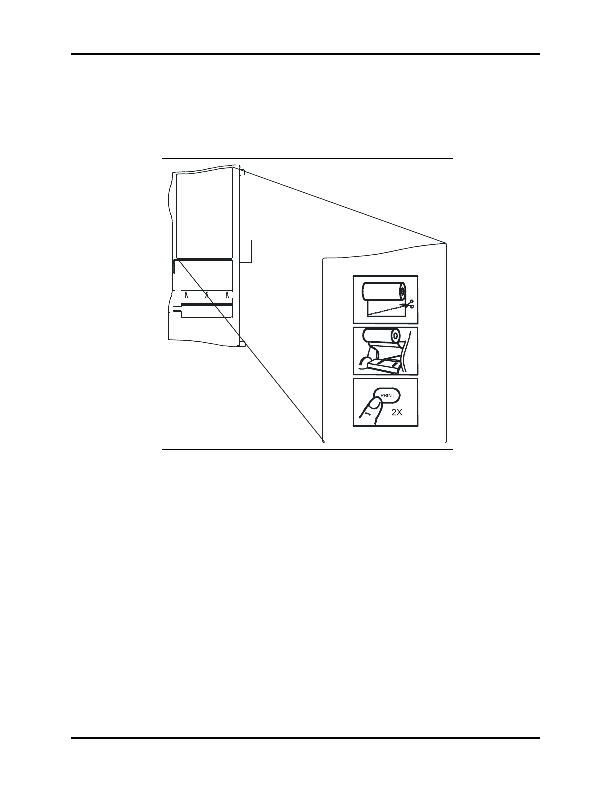
Placement of Recorder Paper Loading Label Operation
3.19 Placement of Recorder Paper Loading Label
The Recorder Paper Loading label is designed to be placed on the recorder module.
Attach label as shown in the figure below.
FIGURE 3-16 Placement of Recorder Paper Loading Label
3 - 40 0070-10-0692-02 Accutorr Plus™ Operating Instructions
Page 74

4.0
User Maintenance
4.1 Introduction
This section of the manual outlines routine maintenance that should be performed by the user.
The Accutorr Plus is designed for stable operation over long periods of time and under
normal circumstances should not require technical maintenance beyond that described in this
section. However, it is recommended that routine maintenance calibration and safety checks
be performed at least once a year, or more often as required by local statutory or hospital
administration practice.
4.2 Care and Cleaning Of Monitor
The monitor enclosure may be cleaned with a mild soap and water solution or ammoniated
window cleaner. Apply cleaning solution to the cloth, not directly onto the monitor. DO NOT
apply large amounts of liquid. DO NOT use abrasive cleaning agents or organic solvents.
Remove dust and dirt particles with a soft sponge moistened with cleaner solution; or a fine,
soft-hair brush. To prevent scratches DO NOT use abrasive cleaning materials. Fingerprints
and stains may be removed by using a liquid lens cleaner and a soft cloth. DO NOT wipe a
dry screen or use alcohol or chlorinated hydrocarbon solvents.
4.2.1 Decontamination of the Accutorr Plus
WAR NIN G: P erf orm this proc ess with the unit powered down and
power cord removed.
Decontamination of a unit that has come in contact with a biological material can be
performed using LpH SE Germicidal detergent. Apply a small amount of detergent to a
disposable wipe (paper based) and wipe down the outside of the unit. Discard the wipe
appropriately. After waiting 10 minutes, use a clean dry wipe to dry the unit.
CAUTION: Do not get the detergent into any vent openings.
Accutorr Plus™ Operating Instructions 0070-10-0692-02 4 - 1
Page 75

Sterilization and Cleaning of Reusable Cuffs User Maintenance
4.3 Sterilization and Cleaning of Reusable Cuffs
4.3.1 Cleaning Cuffs with Bladders
Take out the bladder before cleaning and disinfecting the cuff.
Cleaning
The cuff can be hand washed or machine washed in warm water or with mild detergent. The
bladder can be cleaned with a damp cloth. Air dry the cuff thoroughly after washing.
NOTE: Machine washing may shorten the service life of the cuff.
Disinfection
The cuff may be disinfected with a damp cloth with 70% ethanol or 70% isopropanol. It may
also be disinfected with ultraviolet. The bladder can only be disinfected with ultraviolet.
NOTE: Prolonged use of disinfectant may cause discoloration of the
Replace the bladder after cleaning and disinfecting the cuff, as follows:
1. Place the bladder on the top of the cuff, as the figure shows.
2. Roll the bladder lengthwise and insert it into the large opening. See the figures below.
3. Hold the hose and the cuff and shake the complete cuff until the bladder is in position.
4. Thread the hose from inside the cuff, and out through the small hole under the internal
flap.
FIGURE 4-1 Cuffs with Bladders
cuff.
CAUTION: Do not dry clean the cuff.
Do not press the cuff with a hot iron.
Do not use detergent and disinfectant other than fresh
water, 70% ethanol or 70% isopropanol.
Clean and disinfect the cuff according to the instructions.
4.3.2 Cleaning Bladderless Cuffs
Clean cuffs with warm water and a mild detergent. Do not use a detergent containing hand
conditioners, softeners, or fragrances.
4 - 2 0070-10-0692-02 Accutorr Plus™ Operating Instructions
Page 76

User Maintenance Sterilization and Cleaning of Reusable Cuffs
NIBP cuffs can be sterilized with gamma sterilization without effecting the repeated
performance of the cuff. Steam sterilization is not recommended. Use of a washing liquid
containing bleach is not recommended because chlorine will chemically break down the
urethane on the inside of the cuff.
Antimicrobial Definition
Mindray’s bladderless cuffs are treated with an antimicrobial coating. Antimicrobial
technology effectively controls a broad spectrum of bacteria, fungi, algae and yeasts on a
wide variety of treated substrates.
Accutorr Plus™ Operating Instructions 0070-10-0692-02 4 - 3
Page 77

Battery Maintenance and Replacement User Maintenance
4.4 Battery Maintenance and Replacement
4.4.1 Battery Maintenance
The Accutorr Plus is available with a lithium ion battery. This battery type may be subject to
local regulations regarding disposal. At the end of the battery life, dispose of the battery in
accordance with any local regulations.
CAUTION: Batteries used in this device may present a risk of fire or
chemical burn if mistreated. Do not disassemble, heat above
100°C (212°F), or incinerate. Replace Lithium Ion battery
with P/N: 0146-00-0069 only. Use of another battery may
present a risk of fire or explosion.
CAUTION: Dispose of used battery promptly in accordance with local
laws. Keep away from children. Do not disassemble and do
not dispose of in fire.
CAUTION: Recharge the Lithium ion battery while in the unit at room
temperature. If the Accutorr Plus is being used in a hot
environment, the Lithium Ion battery may not charge when
the unit is connected to AC. This safety feature is important
because charging a hot battery shortens the battery’s life
span.
CAUTION: Remove the battery if the Accutorr Plus is not likely to be
used for an extended period of time.
4 - 4 0070-10-0692-02 Accutorr Plus™ Operating Instructions
Page 78

User Maintenance Battery Maintenance and Replacement
4.4.2 Battery Replacement
1. Open battery compartment door, located on the bottom of the unit, by pressing the
release lever.
2. Press the release lever, located next to the battery, to eject the battery. Slide out the old
battery.
3. Slide in the replacement battery until it clicks into place.
4. Close the battery compartment door.
5. Batteries are shipped partially charged and therefore require charging prior to use. It is
recommended that the Lithium ion battery be charged in a Accutorr Plus for 4 hours
minimum prior to use.
CAUTION: Removing the battery from the Accutorr Plus while the AC
line cord is disconnected may cause the alarm settings to be
reset to their defaults.
Accutorr Plus™ Operating Instructions 0070-10-0692-02 4 - 5
Page 79

Recorder Paper Replacement User Maintenance
4.5 Recorder Paper Replacement
Use only recommended recorder paper, Part Number 0683-00-0447-XX, to insure that the
print quality will be acceptably dark. See Miscellaneous Accessories, section 5.2.5 for part
numbers of various quantities of recorder paper.
NOTE: Use of low grade paper will result in shortened print head
life and poor print quality.
4.5.1 To Install Paper
1. Open recorder door by pulling the door on the upper left side. An indented area is
provided there for ease of opening the door.
2. Remove empty paper spool.
3. Cut or tear off a clean angled edge on a new roll of paper.
FIGURE 4-2 Recorder Paper Installation
4. Sit the new roll of paper inside the door with the free edge coming off the bottom of the
roll.
5. Slide the free edge behind the metal edge at the top of the printer.
6. Press the PRINT key to feed the paper through the printer.
7. Pull through any slack in the roll of paper and then close the recorder door.
4 - 6 0070-10-0692-02 Accutorr Plus™ Operating Instructions
Page 80

User Maintenance Thermal Paper Durability
NOTE: If the paper jams as it is coming out from under the recorder
door, remove the paper cutter to allow for better access to
the paper jam. The paper cutter can be sharp and must be
carefully taken out.
4.6 Thermal Paper Durability
Our thermal paper will perform for at least two years from the date of manufacture. In actual
experience our papers are very stable and should last for many more years under normal
storage conditions.
We do not recommend that our paper be exposed for a long period of time to certain vinyls,
plastics, adhesives, wet-toner copies, or certain carbon papers.
In storage, under normal office filing conditions (70°F, 45% relative humidity), our thermal
paper can be expected to maintain acceptable legibility for many years — the exact period
is dependent upon actual conditions. Under adverse storage conditions such as high
temperatures and/or humidity, papers are less stable.
Our thermal papers use a dye and co-reactant to form an image. The dye is slightly sensitive
to UV light and will exhibit some fading over an extended exposure to normal office light or
shorter exposure to intense UV light. The degree of fading depends upon:
A. The degree to which the image was developed originally.
B. The intensity of the UV light.
C. The percentage of UV in a light source.
D. The dyes in a particular paper.
While black image papers are inherently more stable, none of the papers are fade proof.
Some image intensity/color change will occur under prolonged and severe exposure to UV
light.
Therefore:
• Store paper in a cool, dry place
• Do not subject finished records to exposure to sunlight or storage over 120°F
• Finished records may fade if exposed to transparent adhesive tape or clear plastic page
protectors
Accutorr Plus™ Operating Instructions 0070-10-0692-02 4 - 7
Page 81

Thermal Paper Durability User Maintenance
This page intentionally left blank.
4 - 8 0070-10-0692-02 Accutorr Plus™ Operating Instructions
Page 82

5.0
Accutorr Plus Versions and Accessories
5.1 Accutorr Plus Versions
5.1.1 Accutorr Plus with Lithium Ion Battery
DESCRIPTION PART NUMBER
Accutorr Plus NIBP, Lithium Ion battery, English 0998-00-0444-91A
Accutorr Plus NIBP, Lithium Ion battery, German 0998-00-0444-91G
Accutorr Plus NIBP, Lithium Ion battery, Spanish 0998-00-0444-91P
Accutorr Plus NIBP, Lithium Ion battery, French 0998-00-0444-91F
Accutorr Plus NIBP, Lithium Ion battery, Italian 0998-00-0444-91T
5.1.2 Accutorr Plus with Nellcor
®
Pulse Oximetry and Lithium Ion
Battery
DESCRIPTION PART NUMBER
*Accutorr Plus NIBP, Trend, Nellcor
Lithium Ion battery, English
*Accutorr Plus NIBP, Trend, Nellcor
Lithium Ion battery, German
*Accutorr Plus NIBP, Trend, Nellcor
Lithium Ion battery, Spanish
*Accutorr Plus NIBP, Trend, Nellcor
Lithium Ion battery, French
*Accutorr Plus NIBP, Trend, Nellcor
Lithium Ion battery, Italian
* Nellcor SpO
monitor only. Reorders must be placed directly with Nellcor. See Pulse Oximetry Accessories for pricing.
Accutorr Plus™ Operating Instructions 0070-10-0692-02 5 - 1
sensor-one sensor and one cable available for sale with initial purchase of Accutorr
2
®
OxiMax® SpO2,
®
OxiMax® SpO2,
®
OxiMax® SpO2,
®
OxiMax® SpO2,
®
OxiMax® SpO2,
0998-00-0444-93A
0998-00-0444-93G
0998-00-0444-93P
0998-00-0444-93F
0998-00-0444-93T
Page 83

Accutorr Plus Versions Accutorr Plus Versions and Accessories
5.1.3 Accutorr Plus with Masimo SET® Pulse Oximetry and Lithium Ion Battery
DESCRIPTION PART NUMBER
®
Accutorr Plus NIBP, Trend, Masimo SET
Lithium Ion battery, English
Accutorr Plus NIBP, Trend, Masimo SET
Lithium Ion battery, German
Accutorr Plus NIBP, Trend, Masimo SET
Lithium Ion battery, Spanish
Accutorr Plus NIBP, Trend, Masimo SET
Lithium Ion battery, French
Accutorr Plus NIBP, Trend, Masimo SET
Lithium Ion battery, Italian
SpO2,
®
SpO2,
®
SpO2,
®
SpO2,
®
SpO2,
0998-00-0444-94A
0998-00-0444-94G
0998-00-0444-94P
0998-00-0444-94F
0998-00-0444-94T
5 - 2 0070-10-0692-02 Accutorr Plus™ Operating Instructions
Page 84

Accutorr Plus Versions and Accessories Accessories
5.2 Accessories
5.2.1 Hoses, Non Invasive Blood Pressure
DESCRIPTION PART NUMBER
Hose, quick connect to quick connect (1.5 m.) 0683-04-0003
Hose, quick connect to quick connect (3.5 m.) 0683-04-0004
5.2.2 Cuffs, Non Invasive Blood Pressure, Latex Free
5.2.2.1 Reusable Quick Connect
DESCRIPTION PART NUMBER
Reusable NIBP cuffs variety kit, 6 cuffs, (1) small child, (1)
child, (1) small adult, (1) adult, (1) large adult, (1) thigh,
quick connect
Reusable NIBP cuffs variety kit, 6 cuffs, (1) small adult, (2)
adult, (2) large adult, (1) thigh, quick connect
Reusable NIBP cuffs variety kit, 6 cuffs, (1) small child, (2)
child, (3) small adult, quick connect
Reusable NIBP cuff, child, 10–19 cm., quick connect 0683-15-0001-01
Reusable NIBP cuff, small adult, 18–26 cm., quick connect 0683-15-0002-01
Reusable NIBP cuff, adult, 25–35 cm., quick connect 0683-15-0003-01
Reusable NIBP cuff, large adult, 33–47 cm., quick connect 0683-15-0004-01
Reusable NIBP cuff, adult thigh, 46–66 cm., quick connect 0683-15-0005-01
Reusable NIBP cuff, adult long, 25–35 cm., quick connect 0683-15-0006-01
Reusable NIBP cuff, large adult long, 33–47 cm., quick
connect
0020-00-0082-31
0020-00-0082-33
0020-00-0082-32
0683-15-0007-01
5.2.2.2 Disposable Quick Connect, Latex Free
DESCRIPTION PART NUMBER
Disposable NIBP cuff, child, 10–19 cm., quick connect (box
of 10)
Disposable NIBP cuff, small adult, 18–26 cm., quick connect
(box of 10)
Disposable NIBP cuff, adult, 25–35 cm., quick connect (box
of 10)
Disposable NIBP cuff, large adult, 33–47 cm., quick connect
(box of 10)
Disposable NIBP cuff, adult thigh, 46–66 cm., quick connect
(box of 5)
Disposable NIBP cuff, adult long, 25–35 cm., quick connect
(box of 10)
Disposable NIBP cuff, large adult long, 33–47 cm., quick
connect (box of 10)
Accutorr Plus™ Operating Instructions 0070-10-0692-02 5 - 3
0683-14-0001-01
0683-14-0002-01
0683-14-0003-01
0683-14-0004-01
0683-14-0005-01
0683-14-0006-01
0683-14-0007-01
Page 85

Accessories Accutorr Plus Versions and Accessories
5.2.2.3 Disposable Neonatal Quick Connect, Latex Free*
DESCRIPTION PART NUMBER
Neonatal Size 1, 3–6 cm. (box of 10) 0683-
Neonatal Size 2, 5–8 cm. (box of 10) 0683-
Neonatal Size 3, 7–10 cm. (box of 10) 0683-
Neonatal Size 4, 9–13 cm. (box of 10) 0683-
Neonatal Size 5, 12–17 cm. (box of 10) 0683-
* Disposable neonatal cuffs require NIBP 1.5 m. hose, part number 0683-04-0003
23-0001-01
23-0002-01
23-0003-01
23-0004-01
23-0005-01
5 - 4 0070-10-0692-02 Accutorr Plus™ Operating Instructions
Page 86

Accutorr Plus Versions and Accessories Accessories
5.2.3 Oximetry Sensors and Accessories
5.2.3.1 Pulse Oximetry-Masimo SET
DESCRIPTION PART NUMBER
®
LNOP
DCI Adult/Pediatric starter kit (1 reusable adult
sensor, 2 adult and 1 pediatric single patient adhesive
sensors, and one 12’ cable)
®
DCI-Adult reusable finger sensor (with added "flaps"
LNOP
for ambient light shielding and 3’ cable)
®
DCI-12 direct connect adult reusable finger sensor
LNOP
with a 12’ integral cable
®
DCIP-Pediatric/slender digit reusable finger sensor 0600-00-0063
LNOP
®
LNOP
TCI Tip Clip Ear Sensor 0600-00-0110
Ear Clip 0600-00-0086
Ear Hanger (pkg of 5) 0600-00-0087
®
LNOP
YI-Multisite reusable sensor 0600-00-0078
Multisite wrap (box of 100) 0600-00-0081
Multisite wrap, foam (pkg of 12) 0600-00-0083
®
LNOP
DCSC-Adult spot check reusable sensor 0600-00-0077
PC08-SpO
PC12-SpO
LNOP
more than 30 kgs. (pkg of 20)
LNOP
patients more than 10 kgs. and less than 50 kgs. (pkg of 20)
LNOP
patients more than 3 kgs. and less than 20 kgs. (pkg of 20)
Tape, Infant, L-Series (Package of 100) 0600-00-0108
LNOP
patients more than 1 kg. and less than 10 kgs. (pkg of 20)
Adhesive tapes for Neonatal Y single patient adhesive
sensors (pkg of 100)
LNOP
patients more than 1 kg. and less than 10 kgs. (pkg of 20)
Adhesive tapes for Neonatal L single patient adhesive
sensors (pkg of 100)
LNOP
sensors-for patients less than 1 kg. (pkg 20)
Posey wraps for Preterm Neonatal Y single patient adhesive
sensors (pkg of 12)
LNOP
sensors-for patients less than 1 kg. (pkg 20)
Posey wraps for Preterm Neonatal L single patient adhesive
sensors (pkg of 12)
Adult/Pediatric starter kit (two adult and two pediatric single
patient adhesive sensors and one 3.66 m./12’ cable)
cable (2.44 m./8’) 0012-00-1099-01
2
cable (3.66 m./12’) 0012-00-1099-02
2
®
Adt-Adult single patient adhesive sensors for patients
®
Pdt-Pediatric/slender digit single patient sensors for
®
II Inf-L-Infant L single patient adhesive sensors for
®
Neo-Neonatal Y single patient adhesive sensors for
®
II Neo-Neonatal L single patient adhesive sensors for
®
NeoPt-Preterm Neonatal Y single patient adhesive
®
II NeoPt-L-Preterm Neonatal L single patient adhesive
®
LNOP® SpO
2
0020-00-0130
0600-00-0047
0600-00-0120
0600-00-0043-01
0600-00-0044-01
0600-00-0100
0600-00-0045-01
0600-00-0065
0600-00-0099
0600-00-0096
0600-00-0046-01
0600-00-0064
0600-00-0098
0600-00-0097
0020-00-0123-01
Accutorr Plus™ Operating Instructions 0070-10-0692-02 5 - 5
Page 87

Accessories Accutorr Plus Versions and Accessories
DESCRIPTION PART NUMBER
Neonatal Y starter kit (two neonatal and two preterm
0020-00-0123-02
neonatal Y single patient adhesive sensors and one 3.66 m./
12’ cable)
Clothing clips (pkg of 5) 0600-00-0084
Adhesive squares (12 cards/12 squares per card) 0600-00-0085
5.2.3.2 Pulse Oximetry-Masimo SET® LNCS® SpO
DESCRIPTION PART NUMBER
®
Adult/Pediatric starter kit (1 reusable adult sensor, 1
LNCS
adult and 1 pediatric single patient adhesive sensor, and one
3.1m. cable)
®
LNCS
Adult/Pediatric disposable starter kit (1 adult and 1
pediatric single patient adhesive sensor, and 3.1m. cable)
®
Neonatal disposable starter kit (1 Neonate and 1
LNCS
Neonate PreTerm single patient adhesive sensor, and one
3.1m. cable)
®
LNCS
DC-I Adult finger reusable sensor 0600-00-0126
®
DC-IP Pediatric finger reusable sensor 0600-00-0127
LNCS
®
TC-1 Reusable Adult Ear Sensor 0600-00-0128
LNCS
®
LNCS
ADTX Adult single patient adhesive sensors (20/Box) 0600-00-0121
®
PDTX Pediatric single patient adhesive sensors
LNCS
(20/Box)
®
INF-L Infant single patient adhesive sensors (20/Box) 0600-00-0123
LNCS
®
NEO-L Neonatal single patient adhesive sensors
LNCS
(20/Box)
®
NEO PT-L Neonatal preterm single patient adhesive
LNCS
sensors (20/Box)
LNC-4 SpO2 Patient cable, 4' 0012-00-1652
LNC-10 SpO2 Patient cable, 10' 0012-00-1599
LNC-14 SpO2 Patient cable, 14' 0012-00-1653
®
to LNOP® PC series adapter 0012-00-1651
LNCS
Masimo SET
®
AC-1 LNCS® adapter cable 0012-00-1656
2
0020-00-0154
0020-00-0156
0020-00-0155
0600-00-0122
0600-00-0124
0600-00-0125
5.2.3.3 Pulse Oximetry-Nellcor® SpO2*
DESCRIPTION PART NUMBER
cable, DOC-10, OxiMax
SpO
2
* Oximetry-Nellcor
®
OxiMax® SpO2 Replacement sensors are available from
®
0012-00-1464
Nellcor-Puritan Bennet. Phone: 1 800 NELLCOR or WWW.NELLCOR.COM
5.2.4 Recorder Module
DESCRIPTION PART NUMBER
Recorder 0998-00-0127
5 - 6 0070-10-0692-02 Accutorr Plus™ Operating Instructions
Page 88

Accutorr Plus Versions and Accessories Accessories
5.2.5 Temperature Modules/Probes
5.2.5.1 Accutemp/IR Infrared Thermometer Module
Includes one thermometer and one box of 250 disposable thermometer covers.
DESCRIPTION PART NUMBER
Adult 0998-00-0128-01
Pediatric 0998-00-0128-02
Neonatal 0998-00-0128-03
5.2.5.2 Stand-Alone AccuTemp/IR Infrared Thermometer
Includes one thermometer, operator's manual, wall mount and one box of 250 disposable
thermometer covers.
DESCRIPTION PART NUMBER
Adult 0998-00-0128-04
Pediatric 0998-00-0128-05
Neonatal 0998-00-0128-06
Covers for IR Probe, Adult/Neonatal (pkg of 250) 0198-00-0016-01
Covers for IR Probe, Adult/Neonatal (pkg of
2500)
0198-00-0016-03
5.2.5.3 Accutorr Plus Predictive Thermometer Module
Includes one oral and one rectal thermometer and one box of 20 disposable probe covers.
DESCRIPTION PART NUMBER
Predictive Thermometer 0998-00-0129
Predictive Probe, Oral (Replacement) 0206-00-0725-01
Predictive Probe, Rectal (Replacement) 0206-00-0725-02
Covers for Predictive Probe, Package of 500 0198-00-0012-03
Accutorr Plus™ Operating Instructions 0070-10-0692-02 5 - 7
Page 89

Accessories Accutorr Plus Versions and Accessories
5.2.5.4 Welch Allyn SureTemp® Plus Thermometer Kit
Includes wall mount, oral probe 2.7 m., 25 covers, operator's manual and mounting
brackets.
DESCRIPTION PART NUMBER
Welch Allyn SureTemp Plus thermometer kit, locking bracket STPLUSLCK
Welch Allyn SureTemp Plus thermometer kit, non-locking
bracket
Welch Allyn SureTemp Plus thermometer module (without
mounting bracket kit)
Locking mounting bracket kit, SureTemp Plus 0020-00-0153
Non-locking mounting bracket kit, SureTemp Plus 0020-00-0477
SureTemp Plus oral probe, 2.7m. cable and well 0992-00-0213-02
SureTemp Plus rectal probe, 2.7m. cable and well 0992-00-0212-02
Probe covers (box of 1000) 0198-00-0044
STPLUS
0992-00-0198
5.2.6 Manuals
DESCRIPTION PART NUMBER
Operator's Manual, Multi-Language
(English, Spanish, French, German and Italian)
Operator's Manual, English 0070-00-0692-02
Operator's Manual, Spanish 0070-00-0692-03
Service Manual, English 0070-00-0691
5.2.7 Nurse Call Connector
DESCRIPTION PART NUMBER
Nurse Call connecting cable 0012-00-1667
5.2.8 Mounting Assemblies
DESCRIPTION PART NUMBER
Wall mount bracket 0436-00-0247
Wall mount kit and bracket ACTPLUSWMT
Rolling stand with mounting bracket ACCTROLLSTD
5.2.9 Recorder Paper
0070-00-0695
DESCRIPTION PART NUMBER
Recorder paper (5 rolls) 0683-00-0447-02
Recorder paper (10 rolls) 0683-00-0447-03
Recorder paper (20 rolls) 0683-00-0447-04
5 - 8 0070-10-0692-02 Accutorr Plus™ Operating Instructions
Page 90

Accutorr Plus Versions and Accessories Accessories
5.2.10 Battery
DESCRIPTION PART NUMBER
Battery, Lithium-Ion 0146-00-0069
Accutorr Plus™ Operating Instructions 0070-10-0692-02 5 - 9
Page 91

Accessories Accutorr Plus Versions and Accessories
Accutorr Plus
Wall Mount Bracket
0436-00-0247
Accutorr Plus
(Basic/Advanced)
Sample Wall Mount
FIGURE 5-1 Universal Wall Mount Kit (P/N: 0436-00-0247)
FIGURE 5-2 Universal Rolling Stand (P/N: ACCTROLLSTD)
5 - 10 0070-10-0692-02 Accutorr Plus™ Operating Instructions
Page 92

6.0
Appendix
6.1 Phone Numbers and How To Get Assistance
Mindray DS USA, Inc. maintains a network of service representatives and factory-trained
distributors. Prior to requesting service, perform a complete operational check of the
instrument to verify proper control settings. If operational problems continue to exist, contact
the Service Department at (800) 288-2121 (U.S.A. and Canada) or (201) 995-8116
(outside U.S.A. and Canada) for assistance in determining the nearest field service location.
Please include the instrument model number, the serial number, and a description of the
problem with all requests for service.
Any questions regarding the warranty should be directed to the nearest authorized location.
Contact information is provided at the end of this manual.
Accutorr Plus™ Operating Instructions 0070-10-0692-02 6 - 1
Page 93

Specifications Appendix
6.2 Specifications
6.2.1 Systolic Pressure Readout
Number of Digits: 3
Accuracy*: Mean error <
Range: Adult Mode: 55 to 260 mmHg
6.2.2 Diastolic Pressure Readout
Number of Digits: 3
Accuracy*: Mean error less than ±5 mmHg,
Range: Adult Mode: 30 to 200 mmHg
*Tested per ANSI/AAMI SP10-1992, ANSI/AAMI SP10A-1996 methods
6.2.3 NIBP Measurement Cycle Time
Less than 30 seconds average at 80 BPM with 180mmHg pump up pressure, without retries,
motion artifact or arrhythmia with standard adult cuff on a healthy individual. Cycle time is
affected by arm size and wrapping technique.
5 mmHg, Standard deviation
less than <8 mmHg
Pediatric Mode: 55 to 160 mmHg
Neonatal Mode: 45 to 120 mmHg
Standard deviation less than ±8 mmHg
Pediatric Mode: 30 to 150 mmHg
Neonatal Mode: 25 to 100 mmHg
6.2.4 Pulse Rate
Range: 35-245 BPM for Adult and Pediatric
70-245 BPM for Neonates
Display Resolution: 1 BPM
Accuracy: ±3 BPM or ±3%, whichever is greater
6.2.5 Maximum Cuff Pressure
Two means of limiting cuff pressure are provided; a hardware over pressure monitor which
limits the pressure to 330mmHg for Adults, 220mmHg for Pediatrics, and 165mmHg for
Neonates. A software overpressure monitor which vents if the pressure exceeds 300mmHg
for Adults, 200mmHg for Pediatrics and 150mmHg for Neonates. If the hardware over
pressure circuit is tripped in normal operation then the unit must be turned off and back on to
reset the system.
6 - 2 0070-10-0692-02 Accutorr Plus™ Operating Instructions
Page 94

Appendix Specifications
Inflation Source
This inflation source is capable of supplying sufficient air to bring a volume of 700cc’s to a
pressure of 300 mmHg in no more than 35 seconds. If the cuff is not inflated to the desired
pressure within 60 seconds then the cuff is vented and a retry cycle is initiated.
Leak Rate
With the bleed valve closed, the maximum pressure drop shall be 10 mmHg in 90 seconds
measured with a 700cc volume at a differential pressure of 250 mmHg.
Cuff Vent Rate
When the unit is vented, a volume of at least 700 cc’s is reduced from a pressure of 250
mmHg to a pressure of 20 mmHg in a maximum of 14 seconds.
6.2.6 Temperature (Predictive)
Range: 90-110°F, 32-43°C
Display Resolution: 0.1°F, 0.1°C
Accuracy: Meets ASTM E1112-86 for accuracy
6.2.7 SpO
Range: 70-100% SpO
Display Resolution: 1% SpO
SpO2 Response Time: 4.5 to 6.5 seconds
Display Update: Less than 4 seconds
Calibration: Factory Calibrated to Functional Saturation
Accuracy - Nellcor
Pulse Rate Range - Nellcor 21 - 249 BPM
- Nellcor® Performance Specifications
2
®
:* ± 2 digits from 70 - 100% SpO2 - Adult
±3 digits from 70 -100% SpO
<70% unspecified
2
2
- Neonates
2
Accutorr Plus™ Operating Instructions 0070-10-0692-02 6 - 3
Page 95

Specifications Appendix
*Neonatal accuracy specifications are based upon testing the N-3000 and N-25 neonatal
sensors on healthy adult volunteers in induced hypoxia studies, in the range of 70 - 100%
Sp02. The specified accuracy also takes into account published literature which predicts
that there may be small difference in % Sp0
reported by the Oximetry when measurements
2
from adult and fetal blood 100% fetal hemoglobin are compared. Fetal hemoglobin is
present in concentrations varying from 10% to 90% in neonatal blood, and this percentage
declines over time. As the percentage of fetal hemoglobin in neonatal blood declines, the
theoretical effect on accuracy due to this source is reduced.
6.2.8 SpO2 – Masimo® Performance Specifications
Range: 70-100% SpO
Display Resolution: 1% SpO
2
2
Display Update: <4 secs
SpO
Accuracy Saturation during No Motion Conditions1:
2
Adults / Pediatrics: 70% to 100% ± 2
5
<70% unspecified
Neonates (LNOP/LNCS): 70% to 100% ± 3
SpO
Accuracy Saturation during Motion Conditions6:
2
Adults / Pediatrics
2
: 70% to 100% ± 3
<70% unspecified
3
Neonates
Neonates
(LNOP): 70% to 100% ± 4
3
(LNCS): 70% to 100% ± 3
<70% unspecified
Response Time: 10 secs (Display Averaging Time is not user-
SpO
2
selectable for Masimo. It will be set to the
default value of 8 seconds.)
NOTE: This time was measured with post average time at 8
seconds.
Low Perfusion Performance4: >0.02% Pulse Amplitude and %Transmission
>5%
Saturation (%SpO
) ±2 digits
2
Pulse ±3 digits
Wavelengths Emitted: 660nm and 905nm
Maximum Emitted Energy: 30mW at 50μA pulsed
6 - 4 0070-10-0692-02 Accutorr Plus™ Operating Instructions
Page 96

Appendix Specifications
Interfering Substances: Carboxyhemoglobin may erroneously
increase readings. The level of increase is
approximately equal to the amount of
carboxyhemoglobin present. Dyes, or any
substance containing dyes, that change
usual arterial pigmentation may cause
erroneous readings.
Pulse Rate Performance Specifications
Pulse Rate During No Motion Conditions1:
Adult/Pediatric/Neonates: 26 to 239 BPM ±3 digits
Pulse Rate During Motion Conditions
2,3
:
Adult/Pediatric/Neonates: 26 to 239 BPM ±5 digits
Update Rate: Less than 4 seconds
1
The Masimo MS-3 pulse Oximetry with LNOP®•Adt sensors have been validated for no
motion accuracy in human blood studies on healthy adult volunteers in induced hypoxia
studies in the range of 70% to 100% SpO
against a laboratory co-Oximetry and ECG
2
monitor. This variation equals plus or minus one standard deviation. Plus or minus one
standard deviation encompasses 68% of the population.
2
The Masimo MS-3 pulse Oximetry with LNOP®•Adt sensors has been validated for motion
accuracy in human blood studies on healthy adult volunteers in induced hypoxia studies
while performing rubbing and tapping motions at 2 to 4 Hz. At an amplitude of 1 to 2 cm
and non-repetitive motion between 1 to 5 Hz. At an amplitude of 2 to 3 cm in induced
hypoxia studies in the range of 70% to 100% SpO
against a laboratory co-Oximetry and
2
ECG monitor. This variation equals plus or minus one standard deviation. Plus or minus one
standard deviation encompasses 68% of the population.
3
The Masimo MS-3 pulse Oximetry with LNOP®•Neo and LNOP®•NeoPt sensors has
been validated for motion accuracy in human blood studies on neonates while moving the
neonates foot at 2 to 4 Hz at an amplitude of 1 to 2 cm against a laboratory co-Oximetry
and ECG monitor. This variation equals plus or minus one standard deviation. Plus or minus
one standard deviation encompasses 68% of the population.
4
The Masimo MS-3 pulse Oximetry has been validated for low perfusion accuracy in bench
top testing against a Biotek Index 2 simulator and Masimo’s simulator with signal strengths
of greater than 0.02% and a % transmission of greater than 5% for saturation’s ranging
from 70% to 100%. This variation equals plus or minus one standard deviation. Plus or
minus one standard deviation encompasses 68% of the population.
5
The LNOP®•Ear Sensors have an SpO2 accuracy of 70% to 100% ±3.5 for adults during
no motion conditions, however, since the monitor cannot display ½ digits, the accuracy
shall be rounded to ±4 digits.
6
The SpO2 accuracy during motion conditions is not specified for the LNOP®•Ear Sensors.
Accutorr Plus™ Operating Instructions 0070-10-0692-02 6 - 5
Page 97

Specifications Appendix
6.2.9 Battery
Battery Type: Lithium Ion
Number of Batteries: 1
Battery Voltage: 11.1 VDC nominal
Battery Capacity: 4.4 Amp-Hour
Battery Run Time: Accutorr Plus basic model - 9.5 hours from
full charge with new battery at 25
NIBP measurement every 5 minutes and
recorder not in use.
Accutorr Plus advanced models - 7 hours
from full charge with new battery at 25
with 1 NIBP measurement every 5 minutes,
continuous SpO
not in use
measurement and recorder
2
°
C with 1
°
C
Recharge Time: 4 Hours Maximum
6.2.10 Real Time Clock
Resolution: 1 minute
Accuracy: ±1 minute/week
Display Format: 24 hours
Power: The real time clock maintains the time and
date when the instrument is On or in the
Standby mode, connected to AC mains or
running from internal battery for at least ten
years from original assembly. The real time
clock will maintain time and date even if the
instrument’s main battery is disconnected.
6 - 6 0070-10-0692-02 Accutorr Plus™ Operating Instructions
Page 98

Appendix Specifications
6.2.11 Physical Characteristics
• Size (maximum):
Main Unit: 19 cm(W) x 26.93 cm(H) x 20.83 cm (D)
7.5" (W) x 10.6" (H) x 8.2" (D)
Recorder Module: 5.33 cm(W) x 23 cm(H) x 11 cm (D)
2.1" (W) x 9" (H) x 4.25" (D)
Predictive Module: 5.7 cm(W) x 15.9 cm(H) x 11.8 cm (D)
2.25" (W) x 6.25" (H) x 4.63" (D)
Weight: <4.95 kg (11 pounds), depending on
configuration
6.2.12 Environmental Characteristics
• Operating:
Temperature: 10°C to 40°C, 50°F to 104°F (Accutorr Plus
& Recorder)
10°C to 32°C, 50°F to 90°F (Predictive
Thermometer)
Humidity: 15 to 90% max, non-condensing.
Altitude: 1013 hPa to 697 hPa (0 to 10,000 ft.)
Shock and Vibration: Meets IEC 60068-2-27 for shock with peak
acceleration of 15g, 11 mSec duration, half
sine.
Meets EN 60068-2-64 for random vibration
with frequencies of 10 to 2000 Hz,
resolution of 10Hz, 10 minutes per axis,
acceleration spectral density of:
10 Hz to 100 Hz : 1.0 (m/s2)2/Hz
100 Hz to 200 Hz : -3 dB per octave
200 Hz to 2000 Hz : 0.5 (m/s2)2/Hz
Shipping: Meets ISTA Test Procedure 1A
(less than 100 lbs)
• Storage:
Temperature: -15°C to +60°C,
+5°F to 104°F
Humidity: 10 to 95%, non-condensing
Accutorr Plus™ Operating Instructions 0070-10-0692-02 6 - 7
Page 99

Specifications Appendix
6.2.13 Electrical Ratings
Voltage: 100 - 120 / 220 - 240 VAC
Current: 0.85 / 0.5 A
Frequency: 60 / 50 Hz
Power Consumption: 40 W, maximum
6.2.14 Safety Characteristics
Risk (Leakage) Currents
Enclosure Risk (Leakage)
Current: ≤100µA normal operating conditions
≤300µA single fault condition
Patient Source Current: ≤10µA normal operating conditions
≤50µA single fault condition
Patient Sink Current: ≤50µA.
Dielectric Withstand
• 1500 V RMS at 50 or 60 Hz for 1 minute from AC mains hot or neutral to chassis
• 2500 V RMS at 50 or 60 Hz for 1 minute from any patient lead or combination of patient
leads to chassis
NOTE: These two tests satisfy IEC 60601-1 requirements for double
or reinforced insulation (tested at 4000 V RMS) between the
applied part and live parts (between patient leads and AC
mains hot or neutral)
Ground Resistance
• ≤0.1 ohm from the AC mains power inlet module’s ground contact pin to any exposed
metal part which may become energized when measured per IEC 60601-1. A ground
resistance of =0.2 ohm is allowed when measured from the U blade of the supplied AC
line cord to any exposed metal part which may become energized.
6 - 8 0070-10-0692-02 Accutorr Plus™ Operating Instructions
Page 100

Appendix Specifications
6.2.15 Agency Compliance
This monitor is designed to comply with the following agency standards:
Safety, IEC EN 60601-1:1990 +A1:1992 + A2:1995
+A13:1996 / IEC 60601-1:1988
+A1:1991 +A2:1995
Safety, UL UL 60601-1:2003
Safety, Canada CAN/CSA C22.2 No. 601.1-M90 (R2005)
Safety, collateral EN 60601-1-1:2001 / IEC 60601-1-
1:2000
Multifunction EN 60601-2-49:2001 / IEC 60601-2-
49:2001
SpO2 particular ISO 9919:2005
NIBP, particular EN 60601-2-30:2000 / IEC 60601-2-
30:1999
NIBP, IEC EN 1060-1:1995 +A1:2002
NIBP, supplementary EN 1060-3:1997 +A1:2005
NIBP, USA ANSI/ AAMI SP10:2002 +A1:2003
+A2:2006
Programmable EN 60601-1-4:1996 +A1:1999
IEC 60601-1-4:1996 +A1:1999
Temperature ASTM E1112-00:2006 / EN12470-3:2000
Biological ISO 10993-1:2003
Risk EN 14971:2000 +A3:2003
Acoustics EN 60601-1-8:2004 +A1:2006
Random Vibe EN 60068-2-64:1994 / IEC 60068-2-64
+corrig:1993
Shock IEC 60068-2-27:1987
Ingress EN 60529:1991 +A1:2001 +Corr.1:2003
Shipping ISTA Procedure 1A:2001
Drop and Impact ECRI PB 29689:1979
EMC IEC 60601-1-2:2001
Magnetic Fields EN 61000-4-8:1993 +A1:2001
Voltage Dips EN 61000-4-11:2004
Volt Change, Fluctuations and Flicker EN 61000-3-3:1995 +A1:2001 +A2:2005
+IS1:2005
Conducted Immunity EN 61000-4-6:1996 +A1:2001 +A2:2006
Radiated Immunity EN 61000-4-3:2006
ESD EN 61000-4-2:1995 +A1:1998 +A2:2001
EFT EN 61000-4-4:2004
Surge EN 61000-4-5:2006
Radiated and Conducted Emissions EN 55011:1998 +A1:1999 +A2:2002
Harmonic Emissions EN 61000-3-2:2000 +A1:2001 +A2:2005
Accutorr Plus™ Operating Instructions 0070-10-0692-02 6 - 9
 Loading...