

Page 1

Service Manual
™
Anesthesia System
Page 2

Service Manual
™
Anesthesia System
Page 3

A7™ is U.S. trademarks of Mindray DS USA, Inc.
Selectatec® is a registered trademark of Ohmeda.
Copyright © Mindray DS USA, Inc., 2014 to 2016. All rights reserved. Contents of this publication may not be reproduced in
any form without permission of Mindray DS USA, Inc.
046-006272-00 A7™ Service Manual
Page 4

Page 5

Table of Contents
Table of Contents
Foreword ...............................................................................................................................................................................................................................vii
Warnings, Cautions, and Notes.....................................................................................................................................................................................vii
Warnings................................................................................................................................................................................................................................vii
Cautions................................................................................................................................................................................................................................viii
Notes........................................................................................................................................................................................................................................ix
Theory of Operation ............................................................................................................................................ 1 - 1
Introduction..........................................................................................................................................................................................1 - 2
Electrical and Pneumatic Connections .......................................................................................................................................1 - 4
Electrical Connections .......................................................................................................................................................................................1 - 4
Pneumatic Connections (A7)...........................................................................................................................................................................1 - 7
Connections Between Pneumatic Circuit, Breathing System and Ventilator Control Board................................................1 - 10
Gas Flow .............................................................................................................................................................................................. 1 - 12
Pneumatic Circuit Diagram...........................................................................................................................................................................1 - 12
Parts List...............................................................................................................................................................................................................1 - 13
Key to Symbols.................................................................................................................................................................................................. 1 - 14
Description.......................................................................................................................................................................................................... 1 - 14
Anesthesia System Components ............................................................................................................................................... 1 - 42
Auxiliary Outlets................................................................................................................................................................................................ 1 - 42
Work Light Board.............................................................................................................................................................................................. 1 - 42
The Breathing System .................................................................................................................................................................... 1 - 44
Brief Introduction ............................................................................................................................................................................................. 1 - 44
Automatic Mode, Inspiration .......................................................................................................................................................................1 - 44
Automatic Mode, Expiration ........................................................................................................................................................................ 1 - 45
Manual Mode, Inspiration .............................................................................................................................................................................1 - 45
Manual Mode, Expiration............................................................................................................................................................................... 1 - 46
Pneumatic PEEP ................................................................................................................................................................................................1 - 47
Ventilator in Standby ...................................................................................................................................................................................... 1 - 47
Breathing System Components.................................................................................................................................................................. 1 - 47
Ventilator UI ....................................................................................................................................................................................... 1 - 49
Display..................................................................................................................................................................................................................1 - 49
CPU Board ...........................................................................................................................................................................................................1 - 57
Ventilator Control and Drive........................................................................................................................................................ 1 - 60
Mother Board..................................................................................................................................................................................................... 1 - 60
Ventilator Control and Drive Board ...........................................................................................................................................................1 - 70
Battery .................................................................................................................................................................................................................. 1 - 77
Infrared Communication Board .................................................................................................................................................................. 1 - 79
Anesthesia Signal Interface Board.............................................................................................................................................................. 1 - 80
Breathing System Heater...............................................................................................................................................................................1 - 81
Electrical Flow Control System.................................................................................................................................................... 1 - 81
EFCS Monitoring Board .................................................................................................................................................................................. 1 - 81
BFCS Position Board ........................................................................................................................................................................................ 1 - 85
Total Flow Meter Backlight Board ..............................................................................................................................................................1 - 86
Air Flow Sensor Interface Board..................................................................................................................................................................1 - 86
Nitrous Oxide Flow Sensor Interface Board............................................................................................................................................ 1 - 88
O2 Flow Sensor Interface Board.................................................................................................................................................................. 1 - 89
Ventilator Pneumatic- O2 Drive Gas ......................................................................................................................................... 1 - 91
Ventilator Pneumatic Drive...........................................................................................................................................................................1 - 91
Drive Pressure-High Pressure Regulator (200 kPa, 29 psi).................................................................................................................1 - 91
Drive Gas Assembly ......................................................................................................................................................................................... 1 - 91
Tube Color Coding........................................................................................................................................................................................... 1 - 91
Installation Guide ................................................................................................................................................ 2 - 1
Preparation - Additional Material Required ..............................................................................................................................2 - 2
Assembly................................................................................................................................................................................................2 - 3
Unpacking and Setup ........................................................................................................................................................................................2 - 3
Breathing System and Breathing System Accessories and Checkout Procedures................................................................... 2 - 18
Vaporizers (if available) .................................................................................................................................................................................. 2 - 18
A7™ Service Manual 046-006272-00 i
Page 6

Table of Contents
Monitoring Products Mounting and Electrical Connection (if available).....................................................................................2 - 19
Functional Tests................................................................................................................................................................................ 2 - 20
Breathing System Leak Test..........................................................................................................................................................................2 - 20
Automatic Backup Flow Control Test........................................................................................................................................................ 2 - 27
Display Setup Check........................................................................................................................................................................................ 2 - 30
Calibrate the AG Module ...............................................................................................................................................................................2 - 30
Gas Module Verification.................................................................................................................................................................................2 - 32
Gas Delivery System Tests............................................................................................................................................................................. 2 - 32
Pneumatic Leak Tests ..................................................................................................................................................................... 2 - 35
Line Pressure Gauges Accuracy Test .........................................................................................................................................................2 - 35
N2O Cylinder Leak Test ..................................................................................................................................................................................2 - 35
O2 Cylinder Leak Test...................................................................................................................................................................................... 2 - 35
AIR Cylinder Leak Test..................................................................................................................................................................................... 2 - 36
Line Pressure Leak Tests................................................................................................................................................................................. 2 - 36
Breathing System Checks.............................................................................................................................................................. 2 - 38
Waste Gas Scavenger Test (if available) ................................................................................................................................................... 2 - 38
Internal Gas Connections Test..................................................................................................................................................................... 2 - 38
Drive Gas Pressure Loss Alarm, N2O Cutoff Test................................................................................................................................... 2 - 42
Performance Verification............................................................................................................................................................... 2 - 43
Manual Mode Ventilation Test.....................................................................................................................................................................2 - 43
APNEA Alarm Test ............................................................................................................................................................................................2 - 43
Alarm Silence Test............................................................................................................................................................................................ 2 - 43
VCV Adult Ventilation Mode Test ............................................................................................................................................................... 2 - 44
VCV Adult Ventilation Mode Test 2............................................................................................................................................................2 - 44
VCV Child Ventilation Mode Test................................................................................................................................................................ 2 - 45
Airway Disconnect Alarm Test..................................................................................................................................................................... 2 - 46
PCV Adult Ventilation Mode Test ............................................................................................................................................................... 2 - 46
Pressure Support (PS) Ventilation Mode Test ........................................................................................................................................ 2 - 47
Alarms and Fail safe Functions.................................................................................................................................................... 2 - 48
Set Up....................................................................................................................................................................................................................2 - 48
Low O2 Alarm Test........................................................................................................................................................................................... 2 - 48
High O2 Alarm Test..........................................................................................................................................................................................2 - 48
Peak Pressure Alarms Test............................................................................................................................................................................. 2 - 49
Minute Volume Alarm Test ...........................................................................................................................................................................2 - 49
Miscellaneous Tests......................................................................................................................................................................... 2 - 50
Test the Line Voltage Alarm.......................................................................................................................................................................... 2 - 50
Top Light and Auxiliary Light Test..............................................................................................................................................................2 - 50
Touchpad Test................................................................................................................................................................................................... 2 - 50
Module Rack Functional Test ....................................................................................................................................................................... 2 - 50
Vaporizer Interlock Test................................................................................................................................................................. 2 - 51
For 2 vaporizer Mount .................................................................................................................................................................................... 2 - 51
For 3 vaporizer Mount .................................................................................................................................................................................... 2 - 51
Vaporizer Accuracy Test ................................................................................................................................................................ 2 - 52
Suction Regulator Test................................................................................................................................................................... 2 - 52
Electrical Tests................................................................................................................................................................................... 2 - 53
Auxiliary Electrical Outlet Test..................................................................................................................................................................... 2 - 53
Electrical Safety Inspection Test..................................................................................................................................................................2 - 53
Electrical Safety Inspection Form................................................................................................................................................................ 2 - 53
Periodic Maintenance.......................................................................................................................................... 3 - 1
Maintenance Schedule .....................................................................................................................................................................3 - 2
Periodical Maintenance Consumable Parts Kits ......................................................................................................................3 - 2
Periodical Maintenance Schedule ................................................................................................................................................3 - 2
Checklist before surgery................................................................................................................................................................... 3 - 3
Visual Inspection Checklist ..............................................................................................................................................................3 - 4
List of Periodic Maintenance Parts to be Replaced and Checked .....................................................................................3 - 4
Battery Maintenance and Replacement .....................................................................................................................................3 - 8
Functional Tests...................................................................................................................................................................................3 - 8
ii 046-006272-00 A7™ Service Manual
Page 7

Table of Contents
Breathing System Leak Test.............................................................................................................................................................................3 - 9
Automatic Backup Flow Control Test........................................................................................................................................................ 3 - 16
Check the AG Module Accuracy................................................................................................................................................................. 3 - 20
Gas Module Verification.................................................................................................................................................................................3 - 21
Gas Delivery System Tests............................................................................................................................................................................. 3 - 21
Check the Sensor Zero Point........................................................................................................................................................................ 3 - 24
Check the Flow Sensor Accuracy................................................................................................................................................................3 - 25
Check the Pressure Sensor Accuracy.........................................................................................................................................................3 - 28
Total Flow Sensor Self Test............................................................................................................................................................................ 3 - 33
Pneumatic Leak Tests ..................................................................................................................................................................... 3 - 33
Line Pressure Gauges Accuracy Test .........................................................................................................................................................3 - 33
N2O Cylinder Leak Test ..................................................................................................................................................................................3 - 34
O2 Cylinder Leak Test...................................................................................................................................................................................... 3 - 34
AIR Cylinder Leak Test..................................................................................................................................................................................... 3 - 34
Line Pressure Leak Tests................................................................................................................................................................................. 3 - 35
Breathing System Checks.............................................................................................................................................................. 3 - 37
Waste Gas Scavenger Test (if available) ................................................................................................................................................... 3 - 37
Internal Gas Connections Test..................................................................................................................................................................... 3 - 37
Drive Gas Pressure Loss Alarm, N2O Cutoff Test................................................................................................................................... 3 - 40
Performance Verification............................................................................................................................................................... 3 - 41
Manual Mode Ventilation Test.....................................................................................................................................................................3 - 41
APNEA Alarm Test ............................................................................................................................................................................................3 - 41
Alarm Silence Test............................................................................................................................................................................................ 3 - 41
VCV Adult Ventilation Mode Test ............................................................................................................................................................... 3 - 42
VCV Child Ventilation Mode Test................................................................................................................................................................ 3 - 42
Airway Disconnect Alarm Test..................................................................................................................................................................... 3 - 43
PCV Adult Ventilation Mode Test ............................................................................................................................................................... 3 - 43
Pressure Support (PS) Ventilation Mode Test ........................................................................................................................................ 3 - 44
Alarms and Fail safe Functions.................................................................................................................................................... 3 - 44
Set Up....................................................................................................................................................................................................................3 - 44
Low O2 Alarm Test........................................................................................................................................................................................... 3 - 45
High O2 Alarm Test..........................................................................................................................................................................................3 - 45
Peak Pressure Alarms Test............................................................................................................................................................................. 3 - 45
Minute Volume Alarm Test ...........................................................................................................................................................................3 - 46
Miscellaneous Tests......................................................................................................................................................................... 3 - 47
Test the Line Voltage Alarm.......................................................................................................................................................................... 3 - 47
Top Light and Auxiliary Light Test..............................................................................................................................................................3 - 47
Touchpad Test................................................................................................................................................................................................... 3 - 47
Module Rack Functional Test ....................................................................................................................................................................... 3 - 47
Vaporizer Interlock Test................................................................................................................................................................. 3 - 48
For 2 vaporizer Mount .................................................................................................................................................................................... 3 - 48
For 3 vaporizer Mount .................................................................................................................................................................................... 3 - 48
Vaporizer Accuracy Test ................................................................................................................................................................ 3 - 49
Suction Regulator Test................................................................................................................................................................... 3 - 49
Electrical Tests................................................................................................................................................................................... 3 - 50
Auxiliary Electrical Outlet Test..................................................................................................................................................................... 3 - 50
Electrical Safety Inspection Test..................................................................................................................................................................3 - 50
Electrical Safety Inspection Form................................................................................................................................................................ 3 - 51
Calibration............................................................................................................................................................ 4 - 1
Introduction..........................................................................................................................................................................................4 - 2
Calibration Warnings, Precautions, and Notes......................................................................................................................... 4 - 2
Warnings.................................................................................................................................................................................................................4 - 2
Cautions..................................................................................................................................................................................................................4 - 2
Notes........................................................................................................................................................................................................................4 - 3
System Calibration..............................................................................................................................................................................4 - 3
Flow Calibration (User)......................................................................................................................................................................................4 - 4
Flow Calibration (Service).................................................................................................................................................................................4 - 8
Pressure Calibration (Service) ......................................................................................................................................................................4 - 30
Pressure and Flow Zeroing (Service) .........................................................................................................................................................4 - 45
A7™ Service Manual 046-006272-00 iii
Page 8

Table of Contents
EFCS Zeroing (User) ........................................................................................................................................................................................4 - 49
Total Flow Sensor Calibration (factory) ....................................................................................................................................................4 - 53
Calibrate the AG Module ...............................................................................................................................................................................4 - 56
..........................................................................................................................................................Cylinder Yoke Regulator Calibration4 - 57
Adjust the back pressure valve....................................................................................................................................................................4 - 60
Repair and Troubleshooting............................................................................................................................... 5 - 1
Troubleshooting Guidelines ...........................................................................................................................................................5 - 2
Identify the problem ..........................................................................................................................................................................................5 - 2
Avoid shorting component leads together...............................................................................................................................................5 - 2
Use the proper equipment ..............................................................................................................................................................................5 - 2
Clean up the repair area....................................................................................................................................................................................5 - 2
Technical Alarms Check....................................................................................................................................................................5 - 3
Startup Alarm Messages ...................................................................................................................................................................................5 - 4
CPU Board Runtime Alarm ...............................................................................................................................................................................5 - 8
Power Board Runtime Alarm...........................................................................................................................................................................5 - 8
Runtime Alarms of Flow Sensor Board.....................................................................................................................................................5 - 10
Ventilator Control Board Runtime Alarm.................................................................................................................................................5 - 16
Real-time Alarms of External AG Module.................................................................................................................................................5 - 19
Runtime Alarms of Internal AG Module ........................................................... 5 - 22
Pneumatic Circuit System Problems......................................................................................................................................... 5 - 23
Tools for on-site Maintenance ..................................................................................................................................................................... 5 - 23
Gas Supplies and Drive Gas ..........................................................................................................................................................................5 - 32
Anesthetic Gas Delivery System..................................................................................................................................................................5 - 41
Breathing System ............................................................................................................................................................................................. 5 - 53
Tidal Volume ...................................................................................................................................................................................................... 5 - 68
Sensors and Valves Problems ...................................................................................................................................................... 5 - 71
Correspondence with Pneumatic Circuit Components ..................................................................................................................... 5 - 71
Correspondence with Hardware Components ..................................................................................................................................... 5 - 71
Preparations before Using Diagnostic Tests........................................................................................................................................... 5 - 72
Zero Points of Flow & Pressure Sensors Problems ............................................................................................................................... 5 - 72
Connections and Measurement of the Flow Sensors Problems......................................................................................................5 - 73
Connections and Measurement of the Pressure Sensors Problems.............................................................................................. 5 - 73
Opening State of the Inspiratory Valve Problems ................................................................................................................................ 5 - 75
Opening States of the PEEP Safety Valve Problems............................................................................................................................. 5 - 75
Opening State of the PEEP Valve Problems............................................................................................................................................5 - 76
Basal Flow Adjustment of O2 Needle Valve............................................................................................................................................ 5 - 77
Hardware and Electrical Problems............................................................................................................................................. 5 - 79
Software Update and Software Configuration Activation................................................................................................ 5 - 81
Repair and Disassembly ...................................................................................................................................... 6 - 1
Prepare for Disassembly...................................................................................................................................................................6 - 2
Tools.........................................................................................................................................................................................................................6 - 2
Preparations ..........................................................................................................................................................................................................6 - 2
Bleed Gas Pressure..............................................................................................................................................................................................6 - 2
Disassemble the Assemblies........................................................................................................................................................... 6 - 3
Disassemble the Internal Assemblies of the Machine Upper Half.....................................................................................................6 - 3
Disassemble Hardware Box ..........................................................................................................................................................................6 - 14
Disassemble the Work Surface.................................................................................................................................................................... 6 - 27
Disassemble the Auxiliary Work Surface.................................................................................................................................................. 6 - 36
Disassemble the Display................................................................................................................................................................................6 - 38
Remove the Module Rack Assembly ......................................................................................................................................................... 6 - 47
Remove the Module Rack Fan .....................................................................................................................................................................6 - 48
Remove the Panel of Pressure Gauges.....................................................................................................................................................6 - 49
Disassemble the Vacuum Suction Related Assembly......................................................................................................................... 6 - 57
Remove the Auxiliary Gas Outlet Assembly............................................................................................................................................ 6 - 59
Remove the Rotating Block of Breathing Circle .................................................................................................................................... 6 - 60
Remove the AGSS Assembly ........................................................................................................................................................................6 - 61
Remove the Electronically Controlled ACGO Drive Valve.................................................................................................................. 6 - 62
Remove the Built-in Anesthesia Module..................................................................................................................................................6 - 63
Remove the ACGO Assembly (electronically controlled)................................................................................................................... 6 - 65
Remove Anesthesia Module Inlet Pipeline Assembly.........................................................................................................................6 - 66
iv 046-006272-00 A7™ Service Manual
Page 9

Table of Contents
Disassemble the Base Assembly................................................................................................................................................................. 6 - 67
Disassemble the Breathing System........................................................................................................................................... 6 - 71
Remove the Breathing Tubes....................................................................................................................................................................... 6 - 71
Remove the Flow Sensor ............................................................................................................................................................................... 6 - 72
Remove the Manual Bag................................................................................................................................................................................6 - 73
Remove the Absorbent Canister................................................................................................................................................................. 6 - 74
Remove the CO2 Bypass Assembly............................................................................................................................................................6 - 76
Remove the Prepak Handle ..........................................................................................................................................................................6 - 77
Remove the Contact Switch of the L-shaped Handle ......................................................................................................................... 6 - 78
Remove the Patient Circle Assembly.........................................................................................................................................................6 - 79
Remove the Bellows Assembly....................................................................................................................................................................6 - 80
Remove the Pop-off Valve Assembly ........................................................................................................................................................ 6 - 81
Disassemble the Expiratory/Inspiratory Check Valve Assemblies ..................................................................................................6 - 82
Remove the Water Collection Cup.............................................................................................................................................................6 - 83
Remove the Airway Pressure Gauge ......................................................................................................................................................... 6 - 84
Remove the Bag Arm ...................................................................................................................................................................................... 6 - 84
Remove the Back Upper Cover and Back Lower Cover Assemblies............................................................................................... 6 - 85
Remove the Front Upper Cover, Median Plate and Front Lower Cover Assemblies ...............................................................6 - 87
Disassemble the Automatic/Manual Ventilation Switch Assembly ............................................................................................... 6 - 90
Remove the APL Valve Assembly ............................................................................................................................................................... 6 - 92
Replacement Parts............................................................................................................................................... 7 - 1
Introduction..........................................................................................................................................................................................7 - 2
Ordering Replaceable Parts.............................................................................................................................................................................7 - 2
Diagrams and Tables..........................................................................................................................................................................................7 - 3
Warranty............................................................................................................................................................... 8 - 1
Warranty Statements.........................................................................................................................................................................8 - 2
Disclaimers ............................................................................................................................................................................................8 - 3
Manufacturer's Responsibility........................................................................................................................................................8 - 3
Phone Numbers and How to Get Assistance............................................................................................................................8 - 3
A7™ Service Manual 046-006272-00 v
Page 10

Table of Contents
This page intentionally left blank.
vi 046-006272-00 A7™ Service Manual
Page 11

Foreword Introduction
Foreword
This Service Manual is intended as a guide for technically qualified personnel performing repair and
calibration procedures.
Warnings, Cautions, and Notes
Please read and adhere to all warnings, cautions, and notes listed here and in the appropriate areas
throughout this manual.
A WARNING is provided to alert the user to potential serious outcomes (death, injury, or serious
adverse events) to the patient or the user.
A CAUTION is provided to alert the user to use special care necessary for the safe and effective use of
the device. They may include actions to be taken to avoid effects on patients or users that may not be
potentially life threatening or result in serious injury, but about which the user should be aware.
Cautions are also provided to alert the user to adverse effects on this device of use or misuse and the
care necessary to avoid such effects.
A NOTE is provided when additional general information is applicable.
Warnings
WARNING: Whenever using anesthetic gases, nitrous oxide, oxygen, or any
WARNING: Use only an approved lubricant on any O-ring in contact with oxygen.
WARNING: For continued protection against fire hazard, replace all fuses with the
WARNING: In order to prevent an electric shock, the machine (protection class I)
WARNING: Remove all accessory equipment from the shelf before moving the
WARNING: Possible explosion hazard. Do not operate machine near flammable
WARNING: The use of anti-static or electrically conductive respiration tubes, when
hospital gas, always follow the appropriate agent evacuation/
collection procedures. Use the hospital gas evacuation system.
Krytox® is the recommended oxygen service lubricant.
specified type and rating.
may only be connected to a correctly grounded mains connection
(socket outlet with grounding contact).
anesthesia machine over bumps or on any inclined surface. Heavy top
loading can cause the machine to tip over causing injury.
anesthetic agents or other flammable substances. Do not use
flammable anesthetic agents (e.g., ether or cyclopropane.)
utilizing high frequency electric surgery equipment, may cause burns
and is therefore not recommended in any application of this machine.
WARNING: Possible electric shock hazard. The machine may only be opened by
authorized service personnel.
A7™ Service Manual 046-006272-00 vii
Page 12

Introduction Cautions
WARNING: Compressed gasses are considered Dangerous Goods/Hazardous
WARNING: Avoid exposure to respiratory gases by always directing the fresh gas
WARNING: When using the AG module to perform AG measurements on the
WARNING: Remove the airway sampling line from the patient’s airway and seal the
WARNING: Before connecting the exhaust line to the sample gas outlet on the
WARNING: Perform factory calibration in the working environment after
Materials per I.A.T.A (International Air Transport Association). and
D.O.T. (Department Of Transport) regulations. It is a violation of federal
and international law to transport dangerous goods without the
packages being appropriately identified, packed, marked, classified,
labeled and documented according to D.O.T. and I.A.T.A. regulations.
Please refer to the applicable I.A.T.A. Dangerous Goods Regulations
and /or the Code of Federal Regulations 49 (Transportation, Parts 171-
180) for further information.
flow from the fresh gas outlet to the waste gas scavenger.
patients who are receiving or have recently received anesthetic
agents,connect the outlet to the waste gas disposal system to prevent
the medical staff from breathing in the anesthetic agents.
sample port while nebulized medications are being
delivered.Nebulized medications interfere with accuracy gas reading.
compact airway module,ensure the other end is connected to the
sample gas return port on the anesthesia machine.Incorrect
connections may cause patient injury.
completion of anesthesia machine assembling.Contact us if factory
calibration is required during system use.
WARNING: Do not perform testing or maintenance on A7 anesthesia machine
WARNING: Items can be contaminated due to infectious patients.Wear sterile
WARNING: Obey infection control and safety procedures.Used equipment may
while it is being used on a patient.Possible injury can result.
rubber gloves.Contamination can spread to you and others.
contain blood and body fluids.
Cautions
CAUTION: This device uses high pressure compressed gas. When attaching or
disconnecting backup gas cylinders, always turn the cylinder valves
slowly. Use the A7 flow meters to bleed down the pressure, watching
the cylinder gauge indicate the depleting cylinder pressure, before
disconnecting the cylinder from the yoke. Always open and close
cylinder valves fully.
CAUTION: This device operates using compressed gas at high pressures from the
CAUTION: Refer to section 3.3 Periodical Maintenance Schedule for assistance
hospital central supply. When connecting gas supply lines attach the
hose connection to the machine before connecting the quick
disconnect fitting to the hospital source. Disconnect the supply hose
from the hospital source connection prior to disconnecting it from the
A7 gas connection fittings.
when performing scheduled periodic maintenance.
viii 046-006272-00 A7™ Service Manual
Page 13

Notes Introduction
CAUTION: Do not leave gas cylinder valves open if the pipeline supply is in use
CAUTION: Use cleaning agent sparingly. Excess fluid could enter the machine,
CAUTION: This machine must only be operated by trained, skilled medical staff.
CAUTION: Perform the electrical safety inspection as the last step after
CAUTION: After changing the CO2 absorbent, carry out a vaporizer and system
CAUTION: Only Selectatec™ compatible vaporizers with Interlock-System may be
CAUTION: After each exchange of a vaporizer, carry out a system Leak test.
CAUTION: Do not clean the machine while it is on and/or plugged in.
CAUTION: Pressing "cancel" at any time during the procedure will cancel the
CAUTION: Depleted sodalime changes color. Replace the sodalime if
and the system master switch is turned to 'ON'. If used simultaneously,
cylinder supplies could be depleted, leaving an insufficient reserve
supply in the event of pipeline failure.
causing damage.
completing a repair or after routine maintenance. Perform this
inspection with all covers, panels, and screws installed.
leak test.
used with the A7 unit.
session's settings and reload the previously-stored calibration
coefficients.
approximately 2/3 of the absorber content is discolored. CO2 absorbent
can be safely changed without stopping mechanical ventilation.
CAUTION: This equipment contains parts sensitive to damage by electrostatic
discharge (ESD). Use ESD precautionary procedures when touching,
removing, or inserting parts or assemblies.
CAUTION: The watertrap collects water drops condensed in the sampling tube and
therefore prevents them from entering the AG module.If the collected
water reaches a certain amount, you should drain it to avoid airway
blockage.
CAUTION: The watertrap has a filter preventing bacterium,vapor and patient
secretions from entering the module.After a long-term use,dust or
other subtances may compromise the performance of the filter or even
block the airway.In the case, replace the watertrap.Replacing the
watertrap once a month is recommended.
CAUTION: Strong scavenging suction on the AG monitor exhaust port nay change
the operating presure of the monitor and cause inaccurate readings or
internal damage.
Notes
NOTE: Unauthorized servicing may void the remainder of the warranty. Check
with the factory or with a local authorized distributor to determine the
warranty status of a particular instrument.
A7™ Service Manual 046-006272-00 ix
Page 14

Introduction Notes
This page intentionally left blank.
x 046-006272-00 A7™ Service Manual
Page 15

1.0
Theory of Operation
Introduction .................................................................................................................................................................................................1-2
Electrical and Pneumatic Connections .......................................................................................................................................1-4
Gas Flow ......................................................................................................................................................................................................1-12
Anesthesia System Components.................................................................................................................................................1-42
The Breathing System......................................................................................................................................................................... 1-44
Ventilator UI............................................................................................................................................................................................... 1-49
Ventilator Control and Drive........................................................................................................................................................... 1-49
Electrical Flow Control System...................................................................................................................................................... 1-81
Ventilator Pneumatic- O2 Drive Gas........................................................................................................................................... 1-91
A7™ Service Manual 046-006272-00 1 - 1
Page 16

Introduction Theory of Operation
1.1 Introduction
The A7 Anesthesia System is a simple and convenient anesthetic gas delivery system that produces
anesthesia gas and controls delivery of anesthesia gas by using a configured vaporizer. It supports
automatic and manual ventilation. It can also monitor various parameters of patients, such as the
airway pressure, inspired tidal volume and expired tidal volume.
The A7 Anesthesia System provides the following ventilation modes:
• Volume Control Ventilation (VCV), which includes the Pressure Limit Ventilation (PLV) function
• Pressure Control Ventilation (PCV) with/without the Volume Guarantee (VG) ventilation mode
• Synchronized Intermittent Mandatory Ventilation (SIMV) with the VC mode
• SIMV with the PC mode
• Pressure Support (PS) ventilation mode
• Spontaneous ventilation in Manual mode with the Airway Pressure Limit (APL) fully open
• Manual Ventilation through the use of a breathing bag
• Electronic Positive End Expiratory Pressure (PEEP) is available in all ventilation modes. Control over
inspiratory flow (Tslope) is possible in PCV, SIMV, and PS modes. Automatic fresh gas
compensation helps patients suffer less from manual changes in fresh gas flow rate. The
traditional bellows system is driven by gas and makes patient ventilation clearly visible.
The A7 fresh gas electronic flow metering system inherits the features of a traditional anesthesia
system and moreover is enhanced in ease of use. The dual-tube electronic flow meter displays more
precise readouts. A knob guard prevents inadvertent movement of the flow control knobs. Gas
supply gauges indicate the pipeline and cylinder gas supply pressures in real time. An auxiliary O2
flow meter is placed on the upper left to make it convenient to read the O2 flow rate. The O2 flush
button is in the traditional position near the front left corner of the table top.
Safety systems within the A7 work to prevent hypoxic mixtures from being delivered to the patient.
Nitrous oxide will not be delivered unless oxygen pressure is present.
The heating system of the A7 patient breathing circuit minimizes condensed water and sends warm
and humidified gas back to the patient. The pressure gauge, APL valve and manual breathing bag of
the patient breathing circuit support fast plug and unplug to facilitate their installation and
maintenance. The APL valve has a rotary knob that provides a clear view of the manual breathing
pressure setting. The sodalime absorber canister can be opened and closed quickly through a handle.
It can absorb sodalime in standard Pre-paks or loose-fill sodalime. A drainage valve is configured for
the sodalime absorber canister.
Two flow sensors are configured on the patient breathing circuit to monitor the flow of inspired and
expired gases and monitor the airway pressure. The operator can rotate and fix the patient breathing
circuit as required. In addition, the patient breathing circuit is equipped with a side plug for gas
leakage detection. The Anesthesia Gas Scavenging System (AGSS) connectors are at the rear of the
A7.
1 - 2 046-006272-00 A7™ Service Manual
Page 17

Theory of Operation Introduction
When the A7 uses AC power supply, the A7 power management system supplies power for its main
system while charging its internal battery. In case of an AC power failure, the A7 operates on battery
power, two new batteries supporting normal running in a minimum of 90 minutes. The main system
switch can power on and off the system. The four auxiliary AC sockets on the A7 at the rear of the
machine operate independent of the main system switch.
NOTE: The warmer for the patient breathing circuit system does not operate
when the A7 is working on battery power.
NOTE: If the main switch is set to OFF, the O2 supply is turned off.
A7™ Service Manual 046-006272-00 1 - 3
Page 18

Electrical and Pneumatic Connections Theory of Operation
1.2 Electrical and Pneumatic Connections
1.2.1 Electrical Connections
FIGURE 1-1
1 - 4 046-006272-00 A7™ Service Manual
Page 19

Theory of Operation Electrical and Pneumatic Connections
No. Description P/N
B1 Power Board (A7) 115-018145-00
B2 Battery Interface Board 801-0631-00109-00
B3 CPU Board 115-040636-00
B4 IndicatorLight Board 051-001257-00
B5 Infrared Communication Board 801-0621-00165-00
B6 Anesthesia Signal Interface Board 801-0613-00033-00
B7 Display Interface Board 051-001258-00
B8 Backlight Inverter Board
B9 Warning Light Board 801-0631-00019-00
B10 Touchscreen Control Board 801-0631-00018-00
B11 Encoder Board 051-001260-00
B12 Flow Meter Lighting Board
B13 Top Lighting Board 801-0631-00039-00
B14 Mother Board
B15-16 Ventilator Control Board 801-0631-00027-00
B17 Sensor Interface Board 801-0631-00089-00
B18 Electronic Flow Control System (EFCS) Monitor Board 115-018150-00
B19 Air Flow Sensor Interface Board 051-001415-01
B20 Nitrous Oxide Flow Sensor Interface Board 051-001416-01
B21-22 O2 Flow Sensor Interface Board 051-001414-01
B23 Total Flow Meter Backlight Board Part of 115-014479-00
B24 BFCS Position Board 051-001286-01
P1 Filter Power 250VAC 15A Panel Mount 801-0631-00029-00
P2 Breaker(10.0A) 801-0631-00030-00
P3-6 Breaker(3.0A) 801-0631-00031-00
P7-10 Auxiliary Output Socket 801-0631-00032-00
P11 Speaker and Connecting cable 801-0631-00038-00
P12 Hardware Box Fan 801-0631-00028-00
P13-14 Lithium-ion Battery 115-018012-00
P15 Button Cell M05-010R03---
P16 Touchpad 801-0631-00052-00
P17 Gas Bench Fan 024-000407-00
P18 Touch Screen 801-0631-00014-00
P19 LCD 115-039181-00
P20-21 Rotary Encoder 010-000150-00
P22 Cable, Lighting Switch 009-000981-00
P23 Circuit Heater 115-034450-00
C1-4 Cable, Power, AC Internal 009-000985-01
051-001519-00 (old)
051-002583-00 (new)
Part of 115-01816500(FDA)
Part of 115-01816600(Canadian)
051-001259-00
051-002662-00 (VGA)
A7™ Service Manual 046-006272-00 1 - 5
Page 20

Electrical and Pneumatic Connections Theory of Operation
No. Description P/N
C5 Cable, Auxiliary Outlet 009-000984-00
C6 Cable, AC power 009-000983-00
C8 Cable, Indicator 009-000977-00
C9 Cable, System Switch 009-001776-00
C10 Cable, Touchpad 009-000972-00
C11 Cable, Patient Monitor 009-002927-00
C12 Cable, ACGO Valve Status 009-002940-00
C13 Cable, Internal AG Module 009-003131-00
C14 Cable, Display 009-000973-00
C15
C16
C17 Cable, Alarm 009-000976-00
C18 Cable, Touch Screen 009-000978-00
C19 Cable, Encoder Board 009-002932-00
C20 Cable, Display Lighting 009-000986-00
C21 Cable, Top Lighting A 009-000982-00
C22 Cable, O2 Pressure Switch 0621-20-69588
C24 2-pin O2 Sensor Pedestal 801-0631-00067-00
C25 Cable, Circuit Switch 0621-20-78593
C26 Cable, Sodalime Canister Switch Cable 009-000987-00
C28 Cable, Breathing System 009-002928-00
C29 Cable, BFCS Position Switch 009-002930-00
C30 Cable, Total Flowmeter Backlight 009-002931-00
C31 Cable, Flowmeter Switch Signal 009-002929-00
C32 Cable, Backup Needle Valve Switch(without N2O) 009-005146-00
C34 Cable, Flow Sensor 009-002481-01
C35 Cable, Flowmeter 3 way Valve B 009-002937-00
C37 Cable, Ventilator 009-000979-00
C39 Cable, Three Way Valve(ACGO) 009-002592-00
0631 inverter control high-voltage lines (old)
0632 screen backlight output cable (new)
0631 inverter cable B (old)
0635 screen LED backlight input cable (new)
009-000974-00 (old)
009-006731-00 (new)
009-000988-00 (old)
009-006382-00 (new)
1 - 6 046-006272-00 A7™ Service Manual
Page 21
Theory of Operation Electrical and Pneumatic Connections
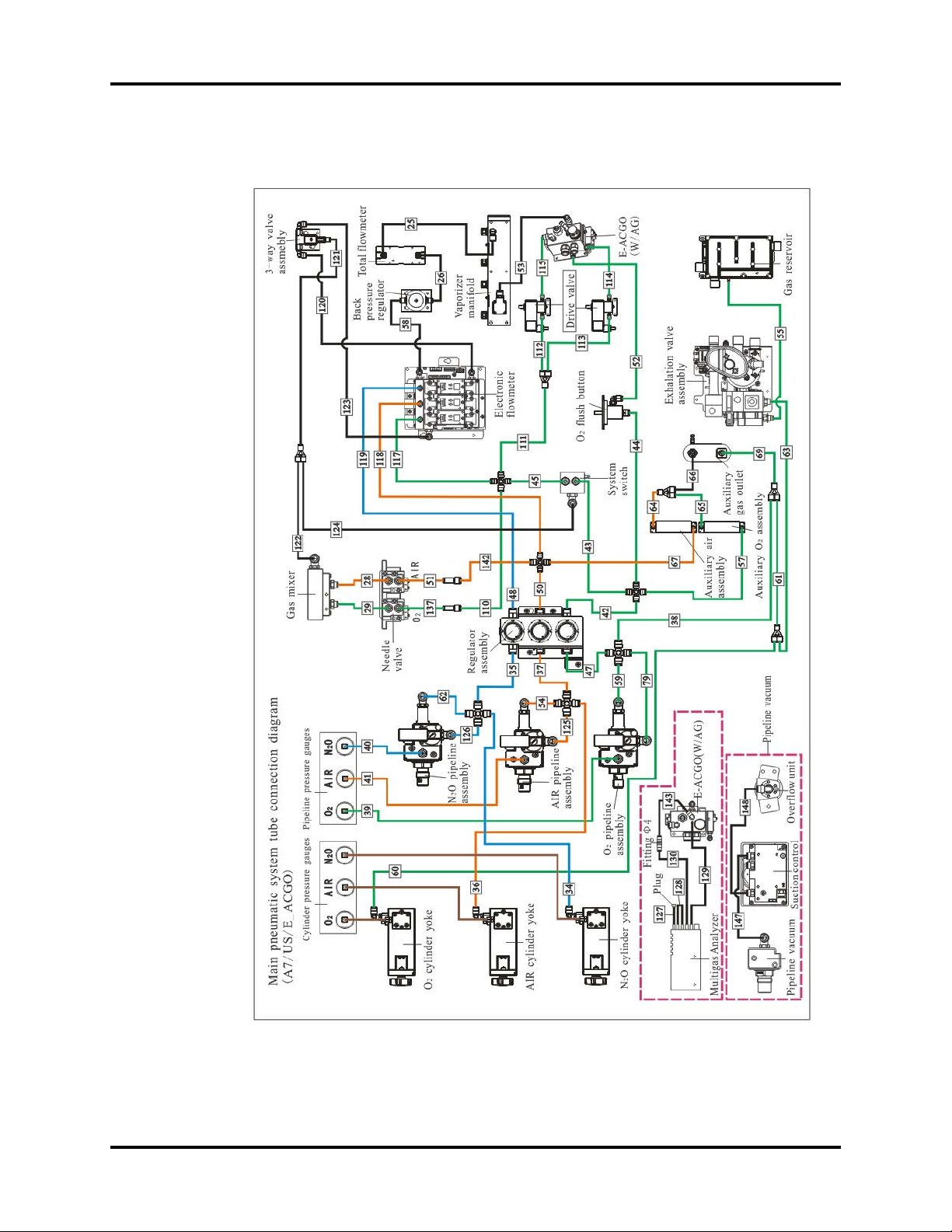
1.2.2 Pneumatic Connections (A7)
FIGURE 1-2
A7™ Service Manual 046-006272-00 1 - 7
Page 22

Electrical and Pneumatic Connections Theory of Operation
S/N From To P/N
25 Total Flow Meter Vaporizer Manifold M6G-020045---
26 Back Pressure Regulator Total Flow Meter M6G-020045---
28 AIR Needle Valve Gas Mixer 082-000518-00
29 O2 Needle Valve Gas Mixer 082-000523-00
34 N2O Cylinder Yoke Y4 082-000662-00
35 Y4 N2O Regulator 082-000662-00
36 Air Cylinder Yoke Y1 or Y4 082-000517-00
37 Y4 Air Regulator 082-000517-00
38 Y4 Y1 082-000521-00
39 O2 Pipeline Pressure Gauge O2 Pipeline Assembly 082-000523-00
40 N2O Pipeline Pressure Gauge N2O Pipeline Assembly 082-000516-00
41 Air Pipeline Pressure Gauge AIR Pipeline Assembly 082-000518-00
42 O2 Regulator Y5 082-000522-00
43 Y5 System Switch 082-000522-00
44 Y5 O2 Flush Button 082-000522-00
45 System Switch Y5 082-000522-00
47 Y4 O2 Regulator 082-000521-00
50 Air Regulator Y5 082-000520-00
51 Y6 Air Needle Valve 082-000518-00
52 O2 Flush Button ACGO Assembly(Electric) 082-000522-00
53 Vaporizer Manifold ACGO Assembly(Electric) M6G-020045---
54 Y4 Air Pipeline Assembly 082-000517-00
55 Exhalation Valve Assembly Gas Reservoir 082-000522-00
57 Y5 Auxiliary O2 Assembly 082-000522-00
58 Electronic Flowmeter Back Pressure Regulator M6G-020045---
59 Y4 O2 Pipeline Assembly 082-000521-00
60 O2 Cylinder Yoke Y1 082-000521-00
61 Y1 Y1 082-000521-00
62 Y4 N2O Pipeline Assembly 082-000662-00
63 Y1 Exhalation Valve Assembly 082-000521-00
64 Auxiliary Air Assembly Y2 082-000520-00
65 Auxiliary O2 Assembly Y2 082-000522-00
66 Y2 Auxiliary Gas Outlet M6G-020026---
67 Y5 Auxiliary Air Assembly 082-000520-00
69 Y1 Auxiliary Gas Outlet 082-000521-00
79 Y4 O2 Pipeline Assembly 082-000521-00
110 Y5 Y6 082-000522-00
111 Y5 Y2 082-000522-00
112 Y2 Drive Valve(UP) 082-000522-00
113 Y2 Drive Valve(DOWN) 082-000522-00
114 Drive Valve(DOWN) ACGO Assembly(Electric) 082-000522-00
115 Drive Valve(UP) ACGO Assembly(Electric) 082-000522-00
1 - 8 046-006272-00 A7™ Service Manual
Page 23

Theory of Operation Electrical and Pneumatic Connections
S/N From To P/N
117 Y5 Electronic Flowmeter 082-000522-00
118 Y5 Electronic Flowmeter 082-000520-00
119 N2O Regulator Electronic Flowmeter 082-000516-00
120 Electronic Flowmeter 3-way Valve Assembly M6G-020045---
121 Y1 3-way Valve Assembly M6G-020045---
122 Gas Mixer Y1 M6G-020045---
123 3-way Valve Assembly Electronic Flowmeter M6G-020045---
124 Y1 System Switch M6G-020045---
125 Y4 AIR Pipeline Assembly 082-000517-00
126 Y4 N2O Pipeline Assembly 082-000662-00
127 Multigas Analyzer Plug 9200-10-10556
128 Multigas Analyzer Multigas Analyzer 9200-10-10556
129 Multigas Analyzer
130 Fitting Φ4 Multigas Analyzer 115-017879-00
137 Y6 O2 Needle Valve 082-000523-00
142 Y5 Y6 082-000520-00
143
147 Pipeline Vacuum Suction Control M6G-020045---
148 Suction Control Over flow Unit M6G-020045---
Y1 Three-way Connector 8 \ 082-000583-00
Y2 Three-way Connector 6 \ 082-000582-00
Y4 Four-way Connector 8 \ 082-001197-00
Y5 Four-way Connector 6 \ 082-001201-00
Y6 Two-way Connector 6 to 4 \ 082-001285-00
Gas-out Connector of ACGO
Connector
Gas-out Connector of ACGO
Connector
Fitting Φ4 082-002600-00
9200-10-10557
A7™ Service Manual 046-006272-00 1 - 9
Page 24

Electrical and Pneumatic Connections Theory of Operation
1.2.3 Connections Between Pneumatic Circuit, Breathing System and Ventilator Control Board
FIGURE 1-3
1 - 10 046-006272-00 A7™ Service Manual
Page 25

Theory of Operation Electrical and Pneumatic Connections
S/N From To P/N
1 Exhalation Gas Assembly Flow Sensor connector A21-000007---
2 Exhalation Gas Assembly Hardware Box Connector A21-000007---
3 Exhalation Gas Assembly Flow sensor connector A21-000007---
4 Three-way Valve Ventilator Control Board A21-000007---
5 Three-way Valve Y2 A21-000007---
6 Three-way Valve Ventilator Control Board A21-000007---
7 Three-way Valve Y2 A21-000007---
8 Y2 Ventilator Control Board A21-000007---
9 Y2 Ventilator Control Board A21-000007---
10 Hardware Box Connector Y1 A21-000007---
11 Y1 Breathing System Connector M6G-020046---
12 Hardware Box Connector Y1 A21-000007---
13 Y1 Breathing System Connector M6G-020046---
14 Hardware Box Connector Y1 A21-000007---
15 Y1 Breathing System Connector M6G-020046---
16 Hardware Box Connector Y1 A21-000007---
17 Y1 Breathing System Connector M6G-020046---
18 Exhalation Gas Assembly Gas Reservoir 082-002365-00
21
22
23 Breathing System Connector Exhalation Gas Assembly 115-037606-00
24 Breathing System Connector Gas Reservoir 115-034449-00
72 Hardware Box Connector Ventilator Control Board A21-000007---
80 Hardware Box Connector Ventilator Control Board A21-000007---
82 Hardware Box Connector Ventilator Control Board A21-000007---
84 Hardware Box Connector Ventilator Control Board A21-000007---
86 Hardware Box Connector Y2 A21-000007---
88 Y2 Three-way Valve A21-000007---
94 Y1 Hardware Box Connector A21-000007---
95 Independent Outlet of ACGO Y1 M6G-020046---
96 Hardware Box Connector Three-way Valve A21-000007---
98 Hardware Box Connector Three-way Valve A21-000007---
116 CPC Connector Breathing System Connector M6G-020026---
141 Gas Reservoir Exhaust Gas Letout Pipe 082-002365-00
155 Breathing System Connector Exhalation Gas Assembly 115-037605-00
Y1 Two-way Connector \ M02A-10-25945
Y2 Three-way Connector \ M90-100030---
Gas-out Connector of ACGO
Connector
Gas-out Connector of ACGO
Connector
Independent Outlet of ACGO 082-000519-00
Fresh Gas 082-000519-00
A7™ Service Manual 046-006272-00 1 - 11
Page 26

Gas Flow Theory of Operation
1.3 Gas Flow
1.3.1 Pneumatic Circuit Diagram
62
50
60
59
52
Gas Bench
48
49
45
51
61
44
43
47
33
43
46
45
33
Pipeline Suction
66
67
68
69
70
53
12
1&
54
55
38
57
56
24
58
19
18
17
16
10
23
33
22
21
20
26
25
31
12
1&
27
41
40
30
31
31
19
41
42
AG
39
30
29 29
29
30
29
29
28 28
37
36
35
34
30
32
15
14
13
64
65
63
8
64
11
63
9
12
10
10
15
14
13
8
13
7
11
10
2
9
12
15
14
13
8
13
7
11
10
Supply Inlet
10
4
5
13
9
7
12
10
6
FIGURE 1-4
1 - 12 046-006272-00 A7™ Service Manual
Page 27

Theory of Operation Gas Flow
1.3.2 Parts List
1. O2 Gas Pipeline Connection 36. Check Valve3
2. O
3. N
4. N
5. Air Gas Pipeline Connection 40. Flow Restrictor
6. Air Gas Cylinder Connection 41. Latching Valve
7. Gas Cylinder Pressure Regulator (360kPa) 42. Electronic ACGO valve
8. Pressure Relief Valve (758kPa) 43. Bypass
9. Pressure Relief Valve (Regulator) 44. CO2 Absorber Canister
10. Drive Gas Inlet Filter 45. Inspiratory Check Valve
11. Gas Pipeline Pressure Gauge 46. Airway pressure gauge
12. Gas Cylinder Pressure Gauge 47. Inspiratory Flow Sensor
13. Check valve1 48. Expiratory Flow Sensor
14. Pressure Switch (220kPa) 49. Watertrap
15. Pressure Regulating Valve (200kPa) 50. Gas Bench
16. Pressure Regulator (200kPa) 51. Check valve
17. Inspiratory Flow Control Valve 52. APL valve
18. Inspiratory Flow Sensor 53. Breathing Bag
19. Safety Valve (110 cmH2O) 54. Auto/Manual Bag Switch
20. PEEP Safety Valve 55. Bellows
21. Drive Gas Pressure Switch (140kPa) 56. Pop-off Valve
22. PEEP Proportional Valve 57. Pressure Relief Valve (1kPa,10cmH2O)
23. Flow Restrictor 58. Negative Pressure Check Valve
24. Exhaust Valve 59. Negative Pressure Check Valve (1cmH2O)
25. Electronic Flow Control System 60. Gas Container1
26. O2 Flush Valve 61. Gas Container2
27. System Switch 62. AGSS
28. Needle Valve 63. Auxiliary Air Flowmeter
29. Check Valve2 64. Auxiliary Flow Needle Valve
30. Flow Sensor 65. Auxiliary O2 Gas Power Outlet
31. Proportional Valve 66. Suction Regulator
32. 3-way Valve 67. Vacuum Gauge
33. Pressure Sensor 68. Overflow Safety Trap
34. Backpressure Valve 69. Filter
35. Total Flowmeter 70. Collection Container
Gas Cylinder Connection 37. Dual Vaporizer Block
2
O Gas Pipeline Connection 38. Ventilator
2
O Gas Cylinder Connection 39. Pressure Relief Valve (37.9kPa)
2
A7™ Service Manual 046-006272-00 1 - 13
Page 28

Gas Flow Theory of Operation
1.3.3 Key to Symbols
Filter
Pressure Gauge
Regulator
Check Valve
Gas Supply Connector
Flowmeter
Pressure Switch
1.3.4 Description
1.3.4.1 Anesthetic Gas Delivery System
The anesthetic gas delivery system is connected to the gas supply, anesthetic gas delivery device
(vaporizer) and breathing system. The system inputs N2O, O2 and AIR from the gas supply assembly
and outputs gas mixture of the three gases and anesthetic agent (fresh gas), pure O2 (high-pressure
O2 output , auxiliary O2 supply and flushing O2), or AIR-O2 mixture. The following figure shows the
pneumatic circuit of the anesthetic gas delivery system.The ACGO is configured in electrical modes
Pressure Relief Valve
Flow Control Valve
Flow Restrictor
FIGURE 1-5
1 - 14 046-006272-00 A7™ Service Manual
Page 29

Theory of Operation Gas Flow
1.3.4.2 Gas Supplies
The A7 anesthesia machine supports three gas supplies: O2, N2O and AIR. All the gas supply
interfaces are designed based on IEC 60601-2-13, which prevents misconnection between different
gases. The A7 gas supply inlet assemblies comprise the pipeline gas supply inlet assembly and
cylinder gas supply inlet assembly.
The following describes the O2 gas flow. The difference between the O2 and the AIR/N2O limbs lies
in that the drive gas output and high-pressure O2 output are available at the upstream end of the
regulator (15) on the O2 limb. The configurations of other components are the same. The O2 pipeline
supply inlet assembly includes filter 10, pressure gauge 11, pressure relief valve 8, check valve 13,
pressure switch 14 and regulator 15. The cylinder gas supply inlet assembly includes the filter (10),
pressure gauge (12), pressure reducing valve (7), pressure relief value (9), check valve (13), pressure
switch (14) and regulator (15). Where, the pressure switch (14) and regulator (15) are shared by the
pipeline and cylinder gas supply limbs. The following figure is the block diagram.
The following table lists parameters of key components.
Name Supplier Description of Functions Key Index
Applied to compressed air, O2 and N2O .
Adjusts pressure and ensures
Regulator Camozzi
Pressure
switch
Pressure
relief valve
A7™ Service Manual 046-006272-00 1 - 15
AIR LOGIC
Mindray Prevents gas pressure too high.
constant output pressure at the
regulator outlet.
Reports an alarm when the gas
supply is insufficient. Pressure
switches are configured on the
O2, N2O and air limbs.
Pressure range: 0.05 to 1 MPa (7 to 145 psi)
Flow: 160 L/min (At 10 bar (145 psi) inlet
pressure, 4bar (58 psi) outlet pressure, with
0.5bar (7 psi) drop)
Precision: 0.5 to 100 PSI, +/- 0.5 tolerance on
the initial starting pressure
Alarm type: an alarm will be reported when
the gas supply pressure reduces to 32 PSI.
Pressure resistance: 300 PSI
Startup pressure: 758 kPa±20 kPa (110 psi ±
2.9 psi)
Leakage volume requirement: The leakage
volume should be smaller than 5 ml/min for
a 600 kPa pressure relief valve.
Page 30

Gas Flow Theory of Operation
The following figure shows the physical pipeline gas supply inlet assembly of the system, including
the gas supply inlet assembly and regulators. The gas supply inlet assembly integrates the filter,
pressure relief valve, pressure switch and check valve. Gases regulated by the regulator will be output
to the flow control systems EFCS and BFCS.
FIGURE 1-6
The following figure shows the models of the gas supply inlet assembly and regulator. The gas from
the pipeline gas supply (280~600 kPa) enters the system through the gas supply connector. After
being cleaned by the internal filter of the inlet assembly, the gas is output to the regulator and
degraded to about 200 kPa. (The filter can be replaced after the pipeline gas supply connector is
removed).
FIGURE 1-7
1 - 16 046-006272-00 A7™ Service Manual
Page 31

Theory of Operation Gas Flow
FIGURE 1-8
As shown in the following figure, the gas from the cylinder gas supply is divided into two limbs after
being cleaned by the filter. One limb is directly connected to the high pressure gauge and the other
limb is degraded to 440 kPa by the high pressure reducing valve and then output from the check
valve. After the gas from the cylinder gas supply is mixed with the gas from the pipeline gas supply,
the gas mixture is output to the regulator. Currently, the system provides only a cylinder connector.
The connector complies with CGA V-1. Cylinders of the E size are supported. The capacity of a
cylinder is limited; therefore, it is recommended that the cylinder gas supply is used as the backup
gas supply to prevent gas supply exhaustion.
FIGURE 1-9
A7™ Service Manual 046-006272-00 1 - 17
Page 32

Gas Flow Theory of Operation
FIGURE 1-10
1.3.4.3 System Switch Assembly
The system switch assembly is the pneumatic circuit on-off valve of the breathing system. It controls
the on and off of the pneumatic circuit and provides system power-off signal when the pneumatic
circuit is switched on, implementing synchronous on/off control on the pneumatic and electrical
circuits of the system. When the system switch knob is rotated clockwise, the valve stem pushes the
valve core to switch on the pneumatic circuit and triggers the tact switches on the system switch
assembly to switch on the electrical circuit at the same time. When the system switch knob is rotated
counterclockwise, the pneumatic and electrical circuits will be switched off at the same time. There is
an exhaust limb on the system switch, which functions to exhaust the residual gas in the backup limb
at power-off to prevent the residual gas in the backup limb from lifting the float of the total
flowmeter.
The system switch assembly is equipped with two tact switches, providing the same functions and
located at symmetrical positions. This design is only used to ensure that one tact switch can operate
properly when the other tact switch fails. When the two PINs of either tact switch are shorted, the
system power supply will be switched on.
1 - 18 046-006272-00 A7™ Service Manual
Page 33

Theory of Operation Gas Flow
FIGURE 1-11
1.3.4.4 Flow Control System - EFCS
FIGURE 1-12
A7™ Service Manual 046-006272-00 1 - 19
Page 34

Gas Flow Theory of Operation
The following figure shows the pneumatic block structure of the EFCS. The three gases, after being
regulated, go through the proportional valves, through limb sensors, through the gas mixing
chamber, and into the three-way valve. Then, the gas mixture returns to the total flow sensor and
finally output to the mechanical float flow meter. Hardware boards and various hardware interfaces
are available under the pneumatic block.
FIGURE 1-13
1.3.4.5 Flow Control System - BFCS
The BFCS of the A7 comprises two mechanical needle valves that are used to control the flow of the
O2 and air limbs and control the O2-AIR ratio. After passing through the two independent check
valves in the mixing chamber, the gases of the two limbs are mixed and finally output.
1.3.4.5.1 BFCS - Motor
The motor of the BFCS provides the force for withdrawing the backup needle valve assembly, and
locates and fastens the backup needle valve assembly by using electromagnet.
1 - 20 046-006272-00 A7™ Service Manual
Page 35

Theory of Operation Gas Flow
FIGURE 1-14
1.3.4.5.2 BFCS - Needle Valves
The needle valve assembly controls the valve port openness by converting the rotation movement of
the knobs into the linear movement of the valve core and thus controls the gas flow. The needle
valve assembly is configured with a tact switch. When a needle valve is closed, the valve core triggers
the tact switch to monitor the close status of the needle valve and feed back the status to the control
unit.
The following figure is a model of the BFCS backup needle valve module.
A7™ Service Manual 046-006272-00 1 - 21
Page 36

Gas Flow Theory of Operation
FIGURE 1-15
FIGURE 1-16
1 - 22 046-006272-00 A7™ Service Manual
Page 37

Theory of Operation Gas Flow
1.3.4.5.3 Back Pressure Valve
The back pressure valve stabilizes the pressure at the upstream inlet and prevents continual fluctua-
tion of the system flow due to load changes. The following figure shows the position of the back pres-
sure valve in the system.
FIGURE 1-17
The following figure shows the structure model and the corresponding interface information.
A7™ Service Manual 046-006272-00 1 - 23
Page 38

Gas Flow Theory of Operation
FIGURE 1-18
1.3.4.6 Three-way Valve
The three-way valve is a two-position three-way solenoid valve with two inlets and one outlet. The
two inlets are connected to the outputs of the EFCS and BFCS respectively, whereas the outlet is
connected to the total flow meter. The three-way valve implements pneumatic circuit switching
between the EFCS and BFCS. Upon power-on, the EFCS limb is switched on and the BFCS limb is
switched off; upon power-off, the EFCS limb is switched off and the BFCS limb is switched on. The
following figure shows the position of the three-way valve in the system.
FIGURE 1-19
1 - 24 046-006272-00 A7™ Service Manual
Page 39

Theory of Operation Gas Flow
The following figure shows the structure model and the corresponding interface information.
FIGURE 1-20
1.3.4.7 Total Flow Meter
The mechanical float flow meter (range: 10 L/min, based on the central line of the float (steel ball))
monitors the fresh gas flow. Located on the main limb of the pneumatic circuit, the total flow meter
can monitor the total flow of the EFCS or BFCS. The following figure shows the position of the total
flow meter in the system.
FIGURE 1-21
A7™ Service Manual 046-006272-00 1 - 25
Page 40

Gas Flow Theory of Operation
The following figure shows the structure model and the corresponding interface information.
FIGURE 1-22
1.3.4.8 Vaporizer Manifold
The vaporizer manifold (installation type: Selectatec) is used to bear the vaporizers and provide an
airtight chamber. In the chamber, the gas mixture and anesthetic gas converge into the fresh gas and
output to the downstream ACGO assembly. Each column on the manifold is a two-position three-
way valve. When no vaporizer is installed, the columns are at the original positions and the gas
mixture is delivered to the downstream through the bypass inside the manifold. When vaporizers are
installed, the columns are bended and the gas mixture is delivered to the manifold and output to the
downstream. The following figure shows the position of the vaporizer manifold in the system.
FIGURE 1-23
1 - 26 046-006272-00 A7™ Service Manual
Page 41

Theory of Operation Gas Flow
The following figure shows the structure model and the corresponding interface information.
FIGURE 1-24
1.3.4.9 ACGO Assembly
The ACGO assembly is used to connect the fresh gas output from the vaporizer manifold and the O2
output from the O2 flush device to the breathing circuit of the anesthesia machine or to an
independent outlet. Mechanical and electrical ACGO configurations are available.
The electrical ACGO pushes the valve core by gas pressure after switching on the control gas supply
at a corresponding end to switch the ACGO state. The following figure is the diagram. For example,
the status needs to be switched to ACGO OFF. When this order is received, the two drive gas control
valves (two-position three-way solenoid valves in the upper part of the following figure) of the
electrical ACGO switch to the state shown in the following figure. On the left side (as shown in the
green arrows), the two connectors on the left and right of the valve are connected and the gas outlet
in the middle is closed; on the right side (as shown in the black arrows), the connector on the left is
disconnected and the connector on the right and the gas outlet in the middle are connected. In this
case, the drive O2 from the system switch passes through the control valve on the left, outputs to the
main ACGO valve shown at the lower part of the following figure and drives the valve core in the
middle rightwards. At the same time, the residential gas on the left side of the valve core is released
to the air through the drive gas control valve on the right side. If the gas on the right side is not
released, the drive gas on the left side cannot push the valve core. Therefore, the two states must be
available at the same time. The valve core pushes rightwards by the drive gas to implement ACGO
state switching. Then, the fresh gas will be output from the patient circuit outlet of the ACGO
assembly.
A7™ Service Manual 046-006272-00 1 - 27
Page 42

Gas Flow Theory of Operation
FIGURE 1-25
If the system is configured with the anesthesia calculation function, corresponding sampling connectors will be integrated on the ACGO valve block. The positions (under the work surface) of the ACGO
assembly with the two configurations in the system are similar, as shown in the following figure.
FIGURE 1-26
Independent ACGO Outlet
When the ACGO assembly is switched to the ACGO state, the fresh gas will be output from the inde-
1 - 28 046-006272-00 A7™ Service Manual
Page 43

Theory of Operation Gas Flow
pendent ACGO outlet. Traditionally, the fresh gas is output from the ACGO limb integrated on the patient circuit. By contrast, the independent ACGO outlet is independent from the patient circuit. The
following figure shows the position of the independent ACGO outlet in the system. The gas input is
from the ACGO outlet on the ACGO assembly.
FIGURE 1-27
The following figure shows the structure model and the corresponding interface information.
FIGURE 1-28
1.3.4.10 O2 Flush Button Assembly
The O2 flush assembly is located on the work surface. When the O2 flush button is depressed, O2
rushes into the pneumatic circuit, and will be cut off when this button is released. The O2 supply gas
is at 0.2 MPa (29 psi), after being regulated, goes through the O2 flush valve and into the O2 flush inlet
of the ACGO assembly. The O2 flush assembly is not affected by the system switch. Flushing O2 can
be performed as long as O2 supply is normal. The O2 flush valve has a slide valve structure inside that
ensures automatic reset each time the valve is depressed and released via the spring. The following
figure shows the position of the O2 flush valve in the system.
A7™ Service Manual 046-006272-00 1 - 29
Page 44

Gas Flow Theory of Operation
FIGURE 1-29
The following figure shows the structure model and the corresponding interface information.
FIGURE 1-30
1.3.4.11 Auxiliary Gas Supply Assembly
The auxiliary gas supply assembly is composed of the oxygen and air limbs. Two needle valves are
used to control the flow of the auxiliary oxygen and air supplies, and corresponding glass tube flow
meters are used for flow monitoring. After being mixed, the oxygen and air are output. The following
figure shows the position of the auxiliary gas supply assembly in the system.
1 - 30 046-006272-00 A7™ Service Manual
Page 45

Theory of Operation Gas Flow
FIGURE 1-31
The following figure shows the structure model and the corresponding interface information.
FIGURE 1-32
A7™ Service Manual 046-006272-00 1 - 31
Page 46

Gas Flow Theory of Operation
1.3.4.12 High Pressure O2 Output Assembly
The high pressure O2 input comes from the gas supply (280 to 600 kPa) ( 40 to 87 psi) directly and
provides high pressure O2 for the external ventilation device (jet ventilation devices). See “Auxiliary
Gas Supply Assembly” on page 1-30..
1.3.4.13 Pneumatically-Controlled Module of Anesthetic
The pneumatically-controlled module of the anesthetic ventilator provides drive gas for the patient
to breathe. O2 (or AIR) from the gas supply inlet assembly enters the anesthetic ventilator and is
output in three pathways: drive gas entering the breathing system, drive gas discharged through the
AGSS outlet, and drive gas discharged through the PEEP outlet. The ventilator controls drive gas flow
to implement various ventilation modes and prevent excessively high pressure inside the pneumatic
circuit from injuring the patient. The following figure shows the pneumatic circuit diagram of the
anesthetic ventilator.
FIGURE 1-33
As shown in the preceding figure, the filter (10) filters drive gas again. The regulator (16) regulates
pressure (about 0.2 MPa (29 psi)) inside the pneumatic circuit. The proportional solenoid valve (17)
controls the inlet gas flow. Component 18 is a flow sensor of differential pressure type that monitors
gas flow in the drive gas circuit. The mechanical overpressure valve (19) ensures that the pressure in
the drive gas circuit does not exceed the safety pressure. It releases excess gas when gas pressure
exceeds 11 kPa (110 cm H2O). Component 24 is the expiratory valve.
The PEEP function is performed through the expiratory valve. Component 22 is a low-flow
proportional solenoid valve. When it opens, gas is bled from the pneumatic resistor (23), forming
relatively stable pressure in the pneumatic circuit from component 22 to component 23. Such
pressure is exerted on the membrane of the expiratory valve (24) to form PEEP.
To prevent excessively high pressure inside the pneumatic circuit from injuring the patient and
damaging the equipment, the pressure relief valve (20), which is a solenoid on-off valve, is placed
before the gas pathway of the expiratory valve. Component 21 is a pressure switch. When the drive
gas pressure is less than 140 kPa (20.3 psi), an alarm is triggered. Component 33 is a pressure sensor
that monitors the pressure at the expiratory valve which is closed. The mechanical pressure relief
valve (57) ensures that the tube pressure after the expiratory valve is less than 10 cm H2O.
The following figure is a picture of the pneumatically-controlled module of the anesthetic ventilator.
1 - 32 046-006272-00 A7™ Service Manual
Page 47

Theory of Operation Gas Flow
FIGURE 1-34
1.3.4.14 Breathing System
The breathing system provides a closed loop for the anesthetic gas. The expired gas from the patient
can be inspired in the inspiration phase to maintain the temperature and humidity conditions of the
patient's expired gas. During inspiration, the drive gas depresses the bag inside the bellows to force
the inside gas to enter the patient's lung. During expiration, the patient's expired gas goes into the
bag inside the bellows. The sodalime absorber canister (integrating 43 and 44) absorbs CO2 that the
patient expires. The following figure shows the pneumatic circuit of the breathing system.
A7™ Service Manual 046-006272-00 1 - 33
Page 48

Gas Flow Theory of Operation
FIGURE 1-35
The breathing system is connected to the anesthesia machine main unit through the circuit adapter.
The breathing system is highly integrated, as its tubes are all internal as shown in the following figure.
FIGURE 1-36
1 - 34 046-006272-00 A7™ Service Manual
Page 49

Theory of Operation Gas Flow
FIGURE 1-37
Mechanical and manual ventilation modes are selected through the Auto/Manual ventilation switch.
Excess water condensed from the exhaled gas is collected in the water collection cup, located on the
bottom side of the breathing system.
The breathing system is easily disassembled and is autoclavable at 134
o
C.
A7™ Service Manual 046-006272-00 1 - 35
Page 50

Gas Flow Theory of Operation
1.3.4.14.1 Mechanical Ventilation
FIGURE 1-38
1.3.4.14.1.1 Drive Gas Path
In case of mechanical ventilation, during inspiration, gas flows through the Auto/Manual ventilation
switch (54), sodalime absorber canister (integrating 44 and 43), inspiratory check valve (45), O2
sensor, airway pressure gauge (46), and inspiratory flow sensor (47) to the patient. During expiration,
gas flows through the expiratory flow sensor (48), expiratory check valve (45), and Auto/Manual
ventilation switch (54) to the bellows. Airway pressure is monitored by the airway pressure gauge
(46).
1 - 36 046-006272-00 A7™ Service Manual
Page 51

Theory of Operation Gas Flow
1.3.4.14.1.2 Fresh Gas Path
FIGURE 1-39
• Red arrows: direction of the fresh gas.
• Black arrows: direction of the patient's expired gas.
• Blue arrows: input direction of the drive gas.
• Black dotted arrows: output direction of the drive gas.
1.3.4.14.2 Manual Ventilation
1.3.4.14.2.1 Flow Path
When the Auto/Manual switch is set to Manual, the operator squeezes the manual breathing bag (53)
to supply gas for the breathing system. The APL valve (52) is used to adjust the pressure inside the
pneumatic circuit in case of manual ventilation. When the Auto/Manual switch is set to Auto, the
ventilator mechanically assists or replaces the spontaneous breathing of the patient. The ventilator
controls the drive gas to depress the bag inside bellows (55) and supply gas for the breathing system
according to the selected ventilation mode.
A7™ Service Manual 046-006272-00 1 - 37
Page 52

Gas Flow Theory of Operation
FIGURE 1-40
• Red arrows: direction of the fresh gas.
• Black arrows: direction of the patient's expired gas.
1.3.4.14.3 Gas Bench
As shown in the following figure, the gas bench is an internal path for the sample gas to return to the
breathing circuit at the patient breathing end. This path must ensure that the waste gas is filtered by
the CO2 absorber canister and then arrives at the inspiratory end of the patient. In this way, the waste
gas can be recycled, which increases the utilization of the anesthetic gas. In the following figure, the
red arrows indicate the direction of the anesthetic gas. Currently, this path is integrated into the main
unit of the patient breathing circuit.
1 - 38 046-006272-00 A7™ Service Manual
Page 53

Theory of Operation Gas Flow
FIGURE 1-41
1.3.4.14.4 Anesthesia Calculation Module
The following figure shows the model for electrical ACGO with sampling for anesthesia calculation.
FIGURE 1-42
NOTE: The anesthesia calculation inlet/outlet sampling connectors are
relative to the inlet/outlet of the anesthesia module.
The following figure shows the tube connection of the anesthesia calculation module.
A7™ Service Manual 046-006272-00 1 - 39
Page 54

Gas Flow Theory of Operation
FIGURE 1-43
1.3.4.15 Anesthetic Gas Scavenging System
The Anesthetic Gas Scavenging System (AGSS) is composed of the AGSS transfer system, the AGSS
receiving system, and the AGSS disposal system. Waste gas goes from the exhaust port of the
anesthesia machine through the AGSS transfer system and the AGSS receiving system to the
hospital's waste gas disposal system (AGSS disposal system), as shown below.
FIGURE 1-44
The following figure shows the operational theory of the AGSS. The throttling holes reduce the effect
of negative pressure at the AGSS outlet onto the flow at the entrance. The float helps the user
determine if the disposal system meets the requirement for the minimum pump rate. The filter
provides for filtering of foreign substances to prevent the disposal system from being occluded. The
gas reservoir is connected to the air through pressure compensation openings. When positive or
negative pressure occurs inside the gas reservoir, gas is inputted or outputted to ensure pressure
balance inside the system.
The AGSS transfer system is a clear tube with 30 mm conical connectors at both ends. The inlet of the
transfer system is a female 30 mm conical connector and the outlet a male 30 mm conical connector.
The transfer system is connected to the receiving system through the male 30 mm conical connector.
The receiving system is connected to the receiving hose through the 30 mm connector. The
following picture shows the AGSS structure and the connections between the AGSS transfer system,
receiving system, and disposal system.
1 - 40 046-006272-00 A7™ Service Manual
Page 55

Theory of Operation Gas Flow
FIGURE 1-45
A7™ Service Manual 046-006272-00 1 - 41
Page 56

Anesthesia System Components Theory of Operation
1.4 Anesthesia System Components
1.4.1 Auxiliary Outlets
The A7 anesthesia system has four 125V 15A Hospital Grade auxiliary outlets. Each outlet has one
250V 3A breaker. Additionally, a main breaker limits the combined current of the four outlets to 10A.
FIGURE 1-46 Auxiliary Outlet Diagram for the A7
1.4.2 Work Light Board
1.4.2.1 Top lighting board
FIGURE 1-47 Top Lighting Board, Top View
FIGURE 1-48 Top Lighting Board, Bottom View
The Flow Meter Lighting Board Interface, J1
PIN NAME FUNCTION
1 12V 12V Power Supply of the Flow Meter Lighting board
2GND Ground
3GND Ground
4LIGHT_IN Flow Meter Lighting Control Signal
Lighting Grade Option Switch Interface, J2
1 - 42 046-006272-00 A7™ Service Manual
Page 57

Theory of Operation Anesthesia System Components
PIN NAME FUNCTION
1 HIGH_BRIGHTNESS High Brightness Grade
2 HIGH_BRIGHTNESS High Brightness Grade
3OFF Close Light Grade
4OFF Close Light Grade
5 LOW_BRIGHTNESS Low Brightness Grade
6 LOW_BRIGHTNESS Low Brightness Grade
Power Supply Interface, J3
PIN NAME FUNCTION
1 12V 12V Power Supply of the Top Lighting Board
2GND Ground
3 12V_AUX The 12V Power Supply of the Flow Meter Lighting Board
1.4.2.2 Flow Meter Lighting Board
FIGURE 1-49 Flow Meter Lighting Board, Top View
FIGURE 1-50 Flow Meter Lighting Board, Bottom View
Flow Meter Lighting Board Interface, J1
PIN NAME FUNCTION
1 12V 12V Power Supply of the Flow Meter Lighting board
2GND Ground
3GND Ground
4LIGHT_IN Flow Meter Lighting Control Signal
A7™ Service Manual 046-006272-00 1 - 43
Page 58

The Breathing System Theory of Operation
1.5 The Breathing System
1.5.1 Brief Introduction
The A7 breathing system supports three operating modes: mechanical ventilation, manual
ventilation, and standby. These modes allow the operator to apply proper ventilation strategies
based on the patient's needs.
The types of flow paths through the breathing system vary with the operating mode or status.
1.5.2 Automatic Mode, Inspiration
When the Auto/Manual switch is positioned at Auto, the system closes the manual ventilation path.
Drive gas pushes down on the bellows. Gas flows from the bellows, through the CO2 absorber
canister, and through the inspiratory check valve to the patient.
During inspiration, fresh gas flows into the inspiratory limb, upstream of the inspiratory check valve.
In volume mode, tidal volume is compensated for variations in fresh gas flow to ensure that the
volume delivered to the patient meets the set value.
In pressure mode, the inspiratory pressure is regulated both in gas flow and airway pressure to ensure
the airway pressure is held at the set inspiratory pressure during the patient inspiration.
FIGURE 1-51 Automatic Mode, Inspiration Diagram
1 - 44 046-006272-00 A7™ Service Manual
Page 59

Theory of Operation The Breathing System
1.5.3 Automatic Mode, Expiration
When the Auto/Manual switch is set to Auto, the system closes the manual ventilation path. Drive-
gas flow stops and the exhaust valve opens. Exhaled gas flows from the patient, through the
expiratory check valve, and into the bellows.
Residual drive gas flows out of the bellows dome through the exhaust valve to the scavenging
system (AGSS).
If PEEP is selected, static pressure on the pilot port of the exhaust valve sets the PEEP level.
During exhalation, fresh gas flows backwards through the CO2 absorber into the expiratory limb,
downstream of the expiratory check valve.
FIGURE 1-52 Automatic Mode, Expiration Diagram
1.5.4 Manual Mode, Inspiration
When the Auto/Manual switch is set to Manual, the system closes the Auto ventilation path. Gas
flows from the breathing bag when compressed, through the CO2 absorber canister, into the
breathing circuit, and through the inspiratory check valve to the patient.
During inspiration, fresh gas flows from the machine into the inspiratory limb, upstream of the
inspiratory check valve.
A7™ Service Manual 046-006272-00 1 - 45
Page 60

The Breathing System Theory of Operation
If airway pressure exceeds the set value of the APL Valve, the residual gas will pass through the APL
Valve to the scavenging system (AGSS).
FIGURE 1-53 Manual Mode, Inspiration Diagram
1.5.5 Manual Mode, Expiration
When the Auto/Manual switch is set to Manual, the system closes the Auto ventilation path. Gas
flows from the patient, through the expiratory check valve, and into the breathing bag. During
exhalation, fresh gas enters the Breathing System. Residual fresh gas passes through the APL valve to
the AGSS.
1 - 46 046-006272-00 A7™ Service Manual
Page 61

Theory of Operation The Breathing System
FIGURE 1-54 Manual Mode, Expiration Diagram
1.5.6 Pneumatic PEEP
The PEEP valve regulates the pressure at which the exhaust valve opens. Therefore, if PEEP is selected,
static pressure on the pilot port of the exhalation valve sets the PEEP level during the automatic
ventilation.
1.5.7 Ventilator in Standby
When the anesthesia system is in standby mode, monitoring will be inactive, and automatic
ventilation will be unavailable. The patient should not be ventilated when the system is in standby
mode.
1.5.8 Breathing System Components
1.5.8.1 Ventilation Bellows System
The ventilator's driving system is a flow generator. Driving gas fills the bellows dome to compress the
bellows. The breathing gas is pressed out of the bellows into the patient breathing circuit. The
bellows is refilled with fresh gas and the expired gas from the patient.
A7™ Service Manual 046-006272-00 1 - 47
Page 62

The Breathing System Theory of Operation
1.5.8.2 Manual Breathing Bag
In manual mode, this device acts as a normal breathing bag, enabling the user to ventilate the
patient manually.
1.5.8.3 CO2 Absorber Canister
The sodalime inside the CO2 absorber canister absorbs the carbon dioxide from the exhaled gas. The
CO2 absorber canister accommodates standard sized Pre-paks or loose-fill CO2 absorbent.
1.5.8.4 Inspiratory and Expiratory Valves
To ensure correct gas flow direction to and from the patient, check-valves are integrated in the
inspiratory and expiratory limb of the Breathing System.
1.5.8.5 APL (Airway Pressure Limiting) Valve
In manual mode, the APL Valve acts as a normal spring-loaded pressure relief valve, limiting the
maximum pressure in the Breathing System.
1 - 48 046-006272-00 A7™ Service Manual
Page 63

Theory of Operation Ven tilat or UI
1.6 Ventilator UI
1.6.1 Display
1.6.1.1 Display Interface Board
FIGURE 1-55 Display Interface Board, Top View
FIGURE 1-56 Display Interface Board, Bottom View
Inverter interface, J1
PIN NAME FUNCTION
1 12V Inverter 12V Power Supply
2 12V Inverter 12V Power Supply
3GND Ground
4GND Ground
5 LCD_EN LCD Backlight Enable
6 LCD_BR LCD Backlight Brightness Control
A7™ Service Manual 046-006272-00 1 - 49
Page 64

Ventilator UI Theory of Operation
Warning Light Board Interface, J2
PIN NAME FUNCTION
1 12V Warning Light Board 12V Power Supply
2GND Ground
3 SDA_CPU CPU Board I2C Data Signal
4 SCL_CPU CPU Board I2C Clock Signal
5 3_3V 3.3V Power Supply
6GND Ground
Touch Screen Control Board interface, J4
PIN NAME Function
1 5V 5V Power Supply
2 RXD_TOUCH_PANEL Touch Screen Control Board Serial Port Receive Signal
3 TXD_TOUCH_PANEL Touch Screen Control Board Serial Port Transmit Signal
4GND Ground
Display Control Signal Interface, J5
PIN Name Function
1 LCD_EN LCD Backlight Enable
2 LCD_BR LCD Backlight Brightness Control
3 RXD_TOUCH_PANEL Touch Screen Control Board Serial Port Receive Signal
4 TXD_TOUCH_PANEL Touch Screen Control Board Serial Port Transmit Signal
5GND Ground
6 LED_AC AC Indicator Light Drive Signal
7 LED_BAT Battery Indicator Light Drive Signal
8 SDA_CPU CPU Board I2C Signal
9 SCL_CPU CPU Board I2C Signal
10 TXD_Encoder Serial Port Transmit Signal of the Display Interface Board
11 RXD_Encoder Serial Port Receive Signal of the Display Interface Board
12 Lighting Lighting Control Signal
13 USB+ USB Signal
14 USB- USB Signal
15 Lighting_12V Lighting 12 V Power Supply
16 12V 12V Power Supply
17 12V 12V Power Supply
18 GND Ground
19 GND Ground
20 GND Ground
1 - 50 046-006272-00 A7™ Service Manual
Page 65

Theory of Operation Ven tilat or UI
Display Control Signal Interface, J6
PIN Name Function
1VCC 5 V Power Supply
2GND Ground
3Encoder_A1 Output A of Encoder 1
4Encoder_B1 Output B of Encoder 1
5 Encoder_Y1 Depress of Encoder 1 (Reserved)
6Encoder_A2 Output A of Encoder 2
7Encoder_B2 Output B of Encoder 2
8 Encoder_Y2 Depress of Encoder 2 (Reserved)
1.6.1.2 Warning Light Board
FIGURE 1-57 Warning Light Board, Top View
FIGURE 1-58 Warning Light Board, Bottom View
Warning Light Board Interface, J1
PIN NAME FUNCTION
1 12V 12V Power Supply
2GND Ground
3 MAIN_BRD_SDA CPU Board I2C Data Signal
4 MAIN_BRD_SCL CPU Board I2C Clock Signal
53_3V 3.3V Power Supply
1.6.1.3 Display and Touchscreen
The anesthesia machine is fitted up with a 15-inch 24-bit 1024x768 LVDS display as the main output
component, and a 15-inch touchscreen as the main input component (another touchpad is available
on the A7 anesthesia machine).
A7™ Service Manual 046-006272-00 1 - 51
Page 66

Ventilator UI Theory of Operation
1.6.1.4 Other Components
The display system also includes the backlight inverter board, warningLight board, touchscreen
control board and encoder board. The backlight inverterboard provides backlight for the display; the
warninglight board is used for reporting visual alarms on the anesthesia machine; the touchscreen
control board controls the inputs through the touchscreen and sends processed touchscreen
operation information through a serial port.
1.6.1.5 Backlight Inverter Board
NOTE: System will have a Backlight Inverter Board or a Screen Backlight
Board.
FIGURE 1-59 Backlight Inverter Board, Top View
FIGURE 1-60 Backlight Inverter Board, Bottom View
Inverter Board Interface, J1
PIN NAME FUNCTION
1GND Ground
2GND Ground
3GND Ground
4 BL_ADJ Display Brightness Control Signal
5BL_ON/OFF Inverter Enable Signal
6 12V 12V Power Supply
7 12V 12V Power Supply
8 12V 12V Power Supply
Inverter Board Interface, J2 and J3
PIN NAME FUNCTION
1 High_Voltage High-Voltage Output of the Inverter
2 Low_Voltage Low-Voltage Output of the Inverter
1 - 52 046-006272-00 A7™ Service Manual
Page 67

Theory of Operation Ven tilat or UI
1.6.1.6 Screen Backlight Board
NOTE: System will have a Backlight Inverter Board or a Screen Backlight
Board.
FIGURE 1-61 Screen Backlight Board, Top View
FIGURE 1-62 Screen Backlight Board, Bottom View
Screen Backlight Board Interface, J1
PIN NAME FUNCTION
1 VPP 12V Power Supply
2GND Ground
3 BCON Screen Backlight Enable Signal
4 DIMMING Screen Backlight Control Signal
5NC None Connection
Screen Backlight Board Interface, J2
PIN NAME FUNCTION
1GND Ground
2 PWM Screen Backlight Control PWM Signal
3 LED_EN Screen Backlight Enable Signal
4 VPP 12V Power Supply
A7™ Service Manual 046-006272-00 1 - 53
Page 68

Ventilator UI Theory of Operation
1.6.1.7 Touchscreen Control Board
FIGURE 1-63 Touchscreen Control Board, Top View
FIGURE 1-64 Touchscreen Control Board, Top View
Touchscreen Control Board Interface, J3
PIN NAME FUNCTION
1VCC 5 V Power Supply
2 RXD_touch Serial Port Receive Signal of the Touchscreen Control Board
3 TXD_touch Serial Port Transmit Signal of the Touchscreen Control Board
4GND Ground
1 - 54 046-006272-00 A7™ Service Manual
Page 69

Theory of Operation Ven tilat or UI
1.6.1.8 Encoder Board
FIGURE 1-65 Encoder Board, Top View
FIGURE 1-66 Encoder Board, Bottom View
Encoder Board Interface, J1
PIN NAME FUNCTION
1 VCC 5 V Power Supply (range: 4.75V~5.25V)
2GND Ground
3Encoder_A1 Output A of Encoder 1
4Encoder_B1 Output B of Encoder 1
5 Encoder_Y1 Depress of Encoder 1 (Reserved)
6Encoder_A2 Output A of Encoder 2
7Encoder_B2 Output B of Encoder 2
8 Encoder_Y2 Depress of Encoder 2 (Reserved)
Fresh Flow Sensor Board Interface, J2 and J3
PIN NAME FUNCTION
1 VCC 5 V Power Supply
2 Encoder_A Output A of Encoder
3Encoder_B Output B of Encoder
4 Encoder_Y Depress of Encoder (Reserved)
5GND Ground
6GND Ground
A7™ Service Manual 046-006272-00 1 - 55
Page 70

Ventilator UI Theory of Operation
1.6.1.9 Indicator Light Board
FIGURE 1-67 Indicator Light Board, Top View
FIGURE 1-68 Indicator Light Board, Bottom View
Indicator Light Board interface, J1
PIN NAME FUNCTION
1 LED_BAT Battery Indicator Light Drive Signal
2 LED_AC AC Indicator Light Drive Signal
3GND Ground
1 - 56 046-006272-00 A7™ Service Manual
Page 71

Theory of Operation Ven tilat or UI
1.6.2 CPU Board
FIGURE 1-69 CPU Board, Top View
A7™ Service Manual 046-006272-00 1 - 57
Page 72

Ventilator UI Theory of Operation
FIGURE 1-70 CPU Board, Bottom View
Network Port, J9
PIN NAME FUNCTION
1 TX+ Positive End of Transmit Signal
2 TX- Negative End of Transmit Signal
3 RX+ Positive End of Receive Signal
4 CT1 No Definition
5 CT1 No Definition
6 RX- Negative End of Receive Signal
7 CT2 No Definition
8 CT2 No Definition
USB Interface, J8
PIN NAME FUNCTION
1VCC USB Power Supply
2 DM0 USB Data Signal – (Negative)
3 DP0 USB Data Signal + (Positive)
4GND Ground
5VCC USB Power Supply
6 DM1 USB Data Signal – (Negative)
1 - 58 046-006272-00 A7™ Service Manual
Page 73

Theory of Operation Ven tilat or UI
PIN NAME FUNCTION
7 DP1 USB Data Signal + (Positive)
8GND Ground
RS-232 Interface, J4
PIN NAME FUNCTION
1 NC No Connection
2 RXD RS-232 Receive Signal
3 TXD RS-232 Transmit Signal
4 NC No Connection
5GND Ground
6 NC No Connection
7 NC No Connection
8 NC No Connection
9 NC No Connection
A7™ Service Manual 046-006272-00 1 - 59
Page 74

Ventilator Control and Drive Theory of Operation
1.7 Ventilator Control and Drive
1.7.1 Mother Board
The mother board provides signal interfaces for all boards and electrical components.
FIGURE 1-71 Mother Board, Top View
FIGURE 1-72 Mother Board, Bottom View
1 - 60 046-006272-00 A7™ Service Manual
Page 75

Theory of Operation Ventilator Control and Drive
VCM Interface, J1
PIN NAME FUNCTION
1 SAFE_VALVE Pressure Relief Valve Drive Signal
27VIN Inspiration Valve Drive Signal
3INSP_VALVE Inspiration Valve Drive Signal
4 7VIN_or_5VIN PEEP Valve Drive Signal
5 PEEP_VALVE PEEP Valve Drive Signal
6SOLENOID_VALVE1Three-way Valve 1
7SOLENOID_VALVE2Three-way Valve 2
8SOLENOID_VALVE3Three-way Valve 3
9SOLENOID_VALVE4Three-way Valve 4
10 PNEUM_PRES_SW Pneumatic Block Pressure Switch Signal
11 NC No Connection
12 ACGO_SW ACGO Tact Switch Signal
13 O2_PRE_SW O2 Pressure Switch Signal at Gas Supply Inlet
14 MANU_AUTO_SW Auto/Manual Switch Signal
15 GND Ground
16 CO2_BYPASS_SW Circuit CO2 Absorber Canister Signal
17 O2+ O2 Concentration Signal
18 O2- O2 Concentration Signal
19 TXD_AUX_BRD VPM Serial Port Transmit Signal
20 RXD_AUX_BRD VPM Serial Port Receive Signal
21 GND Ground
22 SDA IIC Data Signal
23 SCL IIC Clock Signal
24 VT Thermal Mass Flow Sensor Temperature Signal
25 VF Differential Pressure Sensor Flow Signal
26 GND Ground
27 TXD_MON_BRD VCM Serial Port Transmit Signal
28 RXD_MON_BRD VCM Serial Port Receive Signal
29 12V 12V Power Supply
30 GND Ground
31 5V VCM Close Pressure Relief Valve Signal
32 5V 5V Power Supply
33 TXD_CALIBRATE Calibration Serial Port Transmit Signal
34 RXD_CALIBRATE Calibration Serial Port Receive Signal
35 GND Ground
36 12V 12V Power Supply
Pneumatic Assembly Interface, J2
PIN NAME FUNCTION
1 7Vout_or_5Vout Pressure Relief Valve Power Supply
2 SAFE_VALVE Pressure Relief Valve Drive Signal
A7™ Service Manual 046-006272-00 1 - 61
Page 76

Ventilator Control and Drive Theory of Operation
PIN NAME FUNCTION
3 7Vout Inspiration Valve Power Supply
4INSP_VALVE Inspiration Valve Drive Signal
5 7Vout_or_5Vout PEEP Valve Power Supply
6 PEEP_VALVE PEEP Valve Drive Signal
7 ACGO+ Positive End of the ACGO Valve Drive Signal
8 ACGO- Negative End of the ACGO Valve Drive Signal
9VBB1 Electromagnet Power Supply
10 GND Ground
11 12VB_4 Stepper Motor Power Supply
12 GND Ground
13 12VB_5 Reserved Three-Way Valve Power Supply
14 VBB2 Power Supply of the EFCS VCM CPU And Total Flow Meter Backlight
15 GND Ground
16 12VB_2 Power Supply of the EFCS VCM
17 GND Ground
18 VF Differential Pressure Sensor Flow Signal
19 12VA_4 12 V Power Supply
20 GND Ground
21 12VB_3 Proportional Valve Power Supply (range: 10.8V~13.2V)
22 GND Ground
23 ACGO_switch ACGO Pressure Switch Signal
24 GND Ground
25 O2_PRE_SW O2 Pressure Switch Signal at Gas Supply Inlet
26 GND Ground
27 PNEUM_PRES_SW Pneumatic Block Pressure Switch Signal
28 GND Ground
29 MANU_AUTO_SW Auto/Manual Switch Signal
30 GND Ground
31 CO2_BYPASS_SW Circuit CO2 Absorber Canister Signal
32 GND Ground
33 NC No Connection
34 GND Ground
35 O2+ O2 Concentration Signal
36 O2- Ground
37 LOOP_SW Circuit Switch
38 GND Ground
39 NTC_R11 Signal of Thermistor 1
40 NTC_R12 Signal of Thermistor 2
41 NTC_R21 Signal of Thermistor 1
42 NTC_R22 Signal of Thermistor 2
43 HEA_PWR_15V Heater Drive Voltage Signal
44 HEA_PWR_15V Heater Drive Voltage Signal
45 GND Ground
1 - 62 046-006272-00 A7™ Service Manual
Page 77

Theory of Operation Ventilator Control and Drive
PIN NAME FUNCTION
46 GND Ground
47 12VA_1 Electronic Flowmeter Power Supply
48 GND Ground
49 RXD_FLOW_BRD Electronic Flowmeter Serial Port Receive Signal
50 TXD_FLOW_BRD Electronic Flowmeter Serial Port Transmit Signal
Display Interface, J3
PIN NAME FUNCTION
1LCD_EN Inverter Enable Signal
2 LCD_BR Inverter Brightness Adjustment Signal
3 RXD_TOUCH_PANEL Touch Screen Control Board Serial Port Receive Signal
4 TXD_TOUCH_PANEL Touch Screen Control Board Serial Port Transmit Signal
5 NC No Connection
6 LED_AC AC Indicator Light Drive Signal
7 LED_BAT Battery Indicator Light Drive Signal
8 MAIN_BRD_SDA CPU Board I2C Signal
9 MAIN_BRD_SCL CPU Board I2C Signal
10 TXD_KEY Serial Port Transmit Signal of the Display Interface Board
11 RXD_KEY Serial Port Receive Signal of the Display Interface Board
12 Lighting Lighting Control Signal
13 USB+ USB Data Signal+
14 USB- USB Data Signal-
15 Lighting_12V Lighting 12 V Power Supply (range: 10.8V~13.2V)
16 12V 12V Power Supply
17 GND Ground
18 GND Ground
19 VCC_LCD
20 VCC_LCD
21 GND Ground
22 GND Ground
23 LVDS_DATA0+ LVDS Data Difference to Positive Signal 0
24 LVDS_DATA0- LVDS Data Difference to Negative Signal 0
25 GND Ground
26 LVDS_DATA1+ LVDS Data Difference to Positive Signal 1
27 LVDS_DATA1- LVDS Data Difference to Negative Signal 1
28 GND Ground
29 LVDS_DATA2+ LVDS Data Difference to Positive Signal 2
30 LVDS_DATA2- LVDS Data Difference to Negative Signal 2
31 GND Ground
32 LVDS_DATA3+ LVDS Data Difference to Positive Signal 3
33 LVDS_DATA3- LVDS Data Difference to Negative Signal 3
Optional Backplane Power Supply or CPU Board Power Supply for
Display
Optional Backplane Power Supply or CPU Board Power Supply for
Display
A7™ Service Manual 046-006272-00 1 - 63
Page 78

Ventilator Control and Drive Theory of Operation
PIN NAME FUNCTION
34 GND Ground
35 LVDS_CLK+ LVDS Clock Difference to Positive Signal
36 LVDS_CLK- LVDS Clock Difference to Negative Signal
37 GND Ground
Infrared Module Rack Interface for Patient Monitor, J4
PIN NAME FUNCTION
1LED_AC AC Indicator Light Drive Signal
2 3V3_Gasbench 3.3V Power Supply
3 12VA_6 12V Power Supply
4 12VA_6 12V Power Supply
5GND Ground
6GND Ground
RXD_Infrared Comm
7
Board
TXD_Infrared Comm
8
Board
9 12VA_5 12V Power Supply
10 Fan_PWM2 PWM Driver Signal for Fan
11 Fan_State2 State Detection Signal for Fan
12 GND Ground
13 LED_BAT1 Battery Indicator Light Drive Signal
14 ACGO_State1 ACGO State Detection Signal 1
15 ACGO_State2 ACGO State Detection Signal 2
16 PCON+ Power ON/OFF Circuit 3.3V
17 PCON- Power ON/OFF Signal
18 TOUCHPAD_5V 5V Power Supply
19 TOUCHPAD_GND Ground
20 TOUCHPAD_USB+ TOUCHPAD_USB Difference to Positive Signal
21 TOUCHPAD_USB- TOUCHPAD_USB Difference to Negative Signal
22 12VA_1 12V Power Supply
23 GND Ground
24 RSVDRXD_AG Built-in AG Module Receive Signal
25 RSVDTXD_AG Built-in AG Module Transmit Signal
Infrared Comm Board Serial Port Receive Signal
Infrared Comm Board Serial Port Transmit Signal
Calibration Interface, J5
PIN NAME FUNCTION
1 NC No Connection
2 NC No Connection
3 NC No Connection
4 NC No Connection
5 NC No Connection
1 - 64 046-006272-00 A7™ Service Manual
Page 79

Theory of Operation Ventilator Control and Drive
PIN NAME FUNCTION
6 12V 12V Power Supply
7 RXD_CALIBRATE Calibration Serial Port Receive Signal
8 TXD_CALIBRATE Calibration Serial port Transmit Signal
9GND Ground
Anesthetic Ventilator Cooling Fan Interface, J7
PIN NAME FUNCTION
1 12VA_3 12V Power Supply
2RSVD Reserved
3 FAN1_STATE Fan Status Signal
4GND Ground
Speaker Interface, J8
PIN NAME FUNCTION
1Speak+ Speaker Positive End
2Speak- Speaker Negative End
Battery Adaptation Board Interface, J9
PIN NAME FUNCTION
1BAT1+ Battery Voltage
2NTC1 Battery Internal Thermistor
3 BC1 Battery In-position Signal
4GND Ground
5BAT2+ Battery Voltage
6NTC2 Battery Internal thermistor
7 BC2 Battery In-position Signal
8GND Ground
Power Board Interface, J10
PIN NAME FUNCTION
1 PLAM Buzzer Drive Signal (drives the buzzer directly)
2 RXD_PWR_BRD Power Board Serial Port (receives signal)
3 LOOP_SW Circuit Switch (reflects if the circuit is in position)
4 TXD_PWR_BRD Power Board Serial Port (transmits signal)
5 NC Power Board Cooling Fan Drive
6GND Ground
7 LED-BAT Battery Status Indicator Light Drive Output
8 LCD_EN Backlight Enable Signal
9 LED-AC AC Status Indicator Light Drive Output
10 LCD_BR Backlight Brightness Control Voltage
A7™ Service Manual 046-006272-00 1 - 65
Page 80

Ventilator Control and Drive Theory of Operation
PIN NAME FUNCTION (Continued)
11 PCON-
12 3.3VBF 3.3V only used for power ON/OFF the machine
13 BAT2+ 2# Battery Input, connect to battery positive end
14 GND Ground
15 BC2F
16 NTC2 2# Lithium-ion Battery Internal Thermistor Signal
17 BAT1+ 1# Battery Input, connect to battery positive end
18 GND Ground
19 BC1F
20 NTC1 1# Lithium-ion Battery Internal Thermistor Signal
21 GND Ground
22 GND Ground
23 HEA_PWR_15V Heat Wire Drive Voltage Output
24 HEA_PWR_15V Heat Wire Drive Voltage Output
25 NTC_R12 Thermistor (for controlling heat wire) Pin 1
26 NTC_R22 Thermistor (for controlling heat wire) Pin 2
27 NTC_R11 Thermistor (for controlling heat wire) Pin 1
28 NTC_R21 Thermistor (for controlling heat wire) Pin 2
29 GND Ground
30 GND Ground
31 3V3 3.3V Supply Voltage Output
32 3V3 3.3V Supply Voltage Output
33 5V 5V Supply Voltage Output
34 GND Ground
35 GND Ground
36 GND Ground
37 12VB #2 12V Power Supply Voltage Output
38 GND Ground
39 12VB #2 12V Power Supply Voltage Output
40 12VB #2 12V Power Supply Voltage Output
41 GND Ground
42 GND Ground
43 12VA #1 12V Power Supply Voltage Output
44 GND Ground
45 12VA #1 12V Power Supply Voltage Output
46 12VA #1 12V Power Supply Voltage Output
47 NC No Connection
48 15V2 15.2V Supply Voltage Output
49 NC No Connection
50 15V2 15.2V Supply Voltage Output
Power ON/OFF Signal, LVTTL Pulse Signal. If this signal is high level, the
system is turned on; if this signal is low level, the system is turned off.
2# Battery Availability Signal. Low level indicates battery available; high
level indicates battery unavailable
1# Battery Availability Signal. Low level indicates battery available; high
level indicates battery unavailable
1 - 66 046-006272-00 A7™ Service Manual
Page 81

Theory of Operation Ventilator Control and Drive
CPU Board Interface, J11
PIN NAME FUNCTION
A1 LCD_VDD LCD Power Supply
A2 GND LCD Ground
A3 NC No Connection
A4 NC No Connection
A5 RXD_HW_OR_JH Infrared Backplane or Patient Monitor Receive Signal
A6 TXD_HW_OR_JH
A7 GND Ground
A8 RXD_AG Built-in AG Module Receive Signal
A9 TXD_AG Built-in AG Module Transmit Signal
A10 GND Ground
A11 UIVCC_USB USB Power Supply
A12 TOUCHPAD_USB+ TOUCHPAD_USB Data Signal +
A13 TOUCHPAD_USB- TOUCHPAD_USB Data Signal -
A14 GND Ground
A15 SCL_CPU CPU Board I2C Clock
A16 SDA_CPU CPU Board I2C Data
A17 GND Ground
A18 MAIN_ACGO_CTRL2 ACGO Control Signal 2
A19 NC No Connection
A20 ACGO_State1 ACGO State Signal 1
A21 NC No Connection
A22 FAN_STATE2 Fan State Detected Signal 2
A23 FAN_STATE1 Fan State Detected Signal 1
A24 GND Ground
A25 3V3 CPU Board Main Power Supply
A26 3V3 CPU Board main Power Supply
A27 GND Ground
A28 GND Ground
A29 5V CPU Board Interface Chip Power Supply
A30 5V CPU Board Interface Chip Power Supply
A31 GND Ground
A32 GND Ground
B1 NC Not Connected
B2 NC Not Connected
B3 NC Not Connected
B4 SPK_OUT+ Speaker Drive Signal +
B5 SPK_OUT- Speaker Drive Signal -
B6 GND Ground
B7 VGA_Red VGA Red Signal
B8 VGA_Green VGA Green Signal
B9 VGA_Blue VGA Blue Signal
Serial Port Receive SignalInfrared Backplane or Patient Monitor Transmit
Signal
A7™ Service Manual 046-006272-00 1 - 67
Page 82

Ventilator Control and Drive Theory of Operation
PIN NAME FUNCTION (Continued)
B10 VGA_HSYNC
B11 VGA_VSYNC VGA Field Frequency Signal
B12 GND Ground
B13 TXD_PWR_BRD Power Board Serial Port Transmit Signal
B14 RXD_PWR_BRD Power Board Serial Port Receive Signal
B15 GND Ground
B16 TXD_FLOW_BRD Fresh Flow Sensor Board Serial Port Transmit Signal
B17 RXD_FLOW_BRD Fresh Flow Sensor Board Serial Port Receive Signal
B18 GND Ground
B19 TXD_TOUCH_PANEL Touch Screen Controller Serial Port Transmit Signal
B20 RXD_TOUCH_PANEL Touch Screen Controller Serial Port Receive Signal
B21 OUT2 Backup Output
B22 ACGO_State2 ACGO State Signal 2
B23 GND Ground
B24 NC No Connection
B25 DISPLAY_USB- Display Interface Board USB Data Signal-
B26 DISPLAY_USB+ Display Interface Board USB Data Signal+
B27 GND Ground
B28 NC No Connection
B29 NC No Connection
B30 NC No Connection
B31 NC No Connection
B32 NC No Connection
C1 GND Ground
C2 LVDS-TO0+ LVDS Data Signal
C3 LVDS-TO0- LVDS Data Signal
C4 GND Ground
C5 LVDS-TO1+ LVDS Data Signal
C6 LVDS-TO1- LVDS Data Signal
C7 GND Ground
C8 LVDS-TO2+ LVDS Data Signal
C9 LVDS-TO2- LVDS Data Signal
C10 GND Ground
C11 LVDS-TO3+ LVDS Data Signal
C12 LVDS-TO3- LVDS Data Signal
C13 GND Ground
C14 LVDS-TOC+ LVDS Clock Signal
C15 LVDS-TOC- LVDS Clock Signal
C16 GND Ground
C17 TXD_MON_BRD Ventilator Control Board Serial Port Transmit Signal
C18 RXD_MON_BRD Ventilator Control Board Serial Port Receive Signal
C19 GND Ground
VGA Line Frequency Signal
1 - 68 046-006272-00 A7™ Service Manual
Page 83

Theory of Operation Ventilator Control and Drive
PIN NAME FUNCTION (Continued)
C20 TXD_AUX_BRD Auxiliary Ventilator Control Board Serial Port Transmit Signal
C21 RXD_AUX_BRD Auxiliary Ventilator Control Board Serial Port Receive Signal
C22 GND Ground
C23 RXD_KEY Serial Port Receive Signal of the Display Interface Board
C24 TXD_KEY Serial Port Transmit Signal of the Display Interface Board
C25 GND Ground
C26 TP_PWR_CTRL Touch Pad Power Supply Control Signal
C27 MAIN_ACGO_CTRL1 ACGO Valve Control Signal 1
C28 FAN_PWM1 Fan Control Signal
C29 FAN_PWM2 Fan Control Signal
C30 IN1 Backup Input Signal
C31 NC No Connection
C32 NC No Connection
Debugging Power ON/OFF Interface, J12
PIN NAME FUNCTION
1 PCON+ Power ON/OFF Signal
2 PCON- Power ON/OFF Signal
Test Point Definition
DESIGNATOR NAME FUNCTION RANGE (Unit: V)
T1 BAT1 Lithium-ion Battery Voltage 1 Fully charged 12.6±5%
T2 BAT2 Lithium-ion Battery Voltage 2 Fully charged 12.6±5%
T3 LED_BAT Battery Indicator Light Drive Signal
T4 TXD_7024
T5 TXD_TOUCH
T6 RXD_7024
T7 RXD_TOUCH
T8 TXD_33209 VPM Serial Port Transmit Signal
T9 TXD_FLOW
T10 RXD_33209 VPM Serial Port Receive Signal
T11 RXD_FLOW
T12 TXD_POWER
T13 RXD_POWER
Auxiliary Ventilator Control Board
Serial Port Transmit Signal
Touch Screen Controller Serial Port
Transmit Signal
Auxiliary Ventilator Control Board
Serial Port Receive Signal
Touch Screen Controller Serial Port
Receive Signal
Fresh Flow Sensor Board Serial Port
Transmit Signal
Fresh Flow Sensor Board Serial Port
Receive Signal
Power Board Serial Port Transmit
Signal
Power Board Serial Port Receive
Signal
With battery: 2.5~3.5;
Without battery: 0~0.4
High level 2.4~5;
Low level 0~0.4
High level 2.4~5;
Low level 0~0.4
High level 2.4~5;
Low level 0~0.4
High level 2.4~5;
Low level 0~0.4
High level 2.4~5;
Low level 0~0.4
High level 2.4~5;
Low level 0~0.4
High level 2.4~5;
Low level 0~0.4
High level 2.4~5;
Low level 0~0.4
High level 2.4~5;
Low level 0~0.4
High level 2.4~5;
Low level 0~0.4
A7™ Service Manual 046-006272-00 1 - 69
Page 84

Ventilator Control and Drive Theory of Operation
DESIGNATOR NAME FUNCTION RANGE (Unit: V)
T14 5V 5V Power Supply 4.75~5.25
T15 3.3V 3.3V Power Supply 3.135~3.465
T16 15V2 15.2V Power Supply 14.44~15.96
T17 12V 12V Power Supply 11.4~12.6
T18 P15V Heater Power Supply 0~15
T19 LED_AC AC Indicator Light Drive Signal
T20 12V1 12V Power Supply 11.4~12.6
T21 12V2 12V Power Supply 11.4~12.6
T22 12V3 12V Power Supply 11.4~12.6
T23 7V 7V Power Supply 6.65~7.35
T24 LCD_EN LCD Backlight Enable Signal
T25 LCD_BR
LCD Backlight Brightness
Adjustment Signal
With AC: 5~3.5;
Without AC: 0~0.4
High level 3.145~3.465; Low
level 0~0.3
Brightest 0~1.5; least bright
4.75~5.25
1.7.2 Ventilator Control and Drive Board
The monitor subsystem performs pressure and flow detection of the anesthetic ventilator and
anesthetic breathing system, valve control, status monitoring collection, accuracy monitoring of
pressure and flow inside the circuit, and accuracy control of tidal volume. The monitor subsystem is
composed of four boards: monitor signal detection board, valve drive board, ventilator sensor
interface board, and VPM (auxiliary ventilator control board).
1 - 70 046-006272-00 A7™ Service Manual
Page 85

Theory of Operation Ventilator Control and Drive
1.7.2.1 Monitor Signal Detection Board
FIGURE 1-73 Monitor Signal Detection Board, Top View
A7™ Service Manual 046-006272-00 1 - 71
Page 86

Ventilator Control and Drive Theory of Operation
FIGURE 1-74 Monitor Signal Detection Board, Bottom View
Monitor Signal Detection Board Communication Interface, J1
PIN NAME FUNCTION
1TXD Serial Port Transmit
2RXD Serial Port Receive
3 12V 12V Power Supply
4GND Ground
5GND Ground
6 12V 12V Power Supply
7 PRST Pressure Relief Valve Control Signal
85V 5V Power Supply
Ventilator Sensor Interface, J3
PIN NAME FUNCTION
1SDA I2C Data Signal
2 SCL I2C Clock Signal
3 VT Thermal Mass Flow Sensor Temperature Signal
4 VF Thermal Mass Flow Sensor Flow Signal
5 12V Sensor Power Supply
6GND Ground
1 - 72 046-006272-00 A7™ Service Manual
Page 87

Theory of Operation Ventilator Control and Drive
VT Calibration Communication Interface, J7
PIN NAME FUNCTION
1 TXD_CALIBRATE Calibration Serial Port Transmit Signal
2 RXD_CALIBRATE Calibration Serial Port Receive Signal
3GND Ground
4 12V 12V Power Supply
Three-way Valve Control Interface, J6
PIN NAME FUNCTION
1 12V Three-way Valve Power Supply
2 SOLENOID_VALVE1 Three-way Valve Control 1
3 12V Three-way Valve Power Supply
4 SOLENOID_VALVE2 Three-way Valve Control 2
5 12V Three-way Valve Power Supply
6 SOLENOID_VALVE3 Three-way Valve Control 3
7 12V Three-way Valve Power Supply
8 SOLENOID_VALVE4 Three-way Valve Control 4
VPM Communication Interface, J5
PIN NAME FUNCTION
1 TXD_AUX_BRD VPM Serial Port Transmit Signal
2 RXD_AUX_BRD VPM Serial Port Receive Signal
3GND Ground
4 12V 12V Power Supply
O2 Cell Detection Interface, J12
PIN NAME FUNCTION
1O2+ O2 Cell +
2O2- O2 Cell -
3GND Ground
Test Point Definition
DESIGNATOR NAME FUNCTION RANGE (unit: V)
T1 O2 O2 Concentration Voltage 0~3.5
T2 PP PEEP Pressure 0.2~4.5
T3 PW Airway Pressure 0.2~4.5
T6 FM Ventilator Flow Detection 0.21~5.25
T8 FE Expiratory Flow Value 0.2~5.5
T9 VAJF3 Offset Voltage 0.602~0.622
T10 10V5 10.5V 10.25~10.75
A7™ Service Manual 046-006272-00 1 - 73
Page 88

Ventilator Control and Drive Theory of Operation
DESIGNATOR NAME FUNCTION RANGE (unit: V)
T11 REF_4V 4.096V Baseline Power Supply 3.096~4.196
T12 1V2 1.2V Baseline Power Supply 1.1~1.3
T13 VADJ_P Offset Voltage 0.602~0.622
T14 FI Inspiratory Flow Value 0.2~5.5
T15 VADJ_FI Offset Voltage 0.602~0.622
T16 TXD1 Serial Port Transmit Signal (to CPU Board) 0~3.3
T17 RXD1 Serial Port Receive Signal (from CPU board) 0~5
T18 TXD2 Serial Port Transmit Signal (for calibration) 0~3.3
T19 RXD2 Serial Port Receive Signal (for calibration) 0~5
T20 VD 7V 6.8~7.6
T21 DVDD 3.3V Digital Voltage 3.15~3.45
T22 AVCC 5V Analog Voltage 4.75~5.25
T23 WDI Watchdog Signal 0~3.3
T24 RST Reset Signal 0~3.3
T25 CLK Clock Signal 0~3.3
T26 SAN1 Signal of Three-way Valve 1 0~12
T27 SAN2 Signal of Three-way Valve 2 0~12
T28 SAN3 Signal of Three-way Valve 3 0~12
T29 SAN4 Signal of Three-way Valve 4 0~12
1.7.2.2 Valve Drive Board
FIGURE 1-75 Valve Drive Board, Top View
1 - 74 046-006272-00 A7™ Service Manual
Page 89

Theory of Operation Ventilator Control and Drive
FIGURE 1-76 Valve Drive Board, Bottom View
Proportional Valve and Pressure Relief Valve Drive Interface, J4
PIN NAME FUNCTION
1 7V Pressure Relief Valve Power Supply
2 SAFE_VALVE Pressure Relief Valve Control Signal
3 7V Inspiration Valve Power Supply
4 INSP_VALVE Inspiration Valve Control Signal
5 7V PEEP Valve Power Supply
6 PEEP_VALVE PEEP Valve Control Signal
Power Supply Interface, J2
PIN NAME FUNCTION
1GND Ground
2GND Ground
3 12V 12V Power Supply
Status Monitor Detection Interface, J8
PIN NAME FUNCTION
1GND Ground
2 PNEUM_PRE_SW Circuit block pressure Switch Signal
3GND Ground
4NC /
5GND Ground
A7™ Service Manual 046-006272-00 1 - 75
Page 90

Ventilator Control and Drive Theory of Operation
PIN NAME FUNCTION
6 QUICK_O2_SW O2 Flushing Pressure Switch Signal
7GND Ground
8 CGO_PRE_SW CGO Switch Signal
9GND Ground
10 O2_PRE_SW O2 Pressure Switch Signal at Gas Supply Inlet
11 GND Ground
12 MANU_AUTO_SW Auto/Manual Switch Signal
Test Point Definition
DESIGNATOR NAME FUNCTION RANGE (unit: V)
T1 K_OUT1 Status Monitor Signal 0~3.45
T2 K_OUT2 Status Monitor Signal 0~3.45
T3 SAFE Pressure Relief Valve Signal 0~7
T4 VOC Reserved DA Output Signal 0~1.2
T5 AD2 Analog Channel Output Signal 0~5
T6 FLOW Inspiration Valve Control Signal 0~7
T7 PEEP PEEP Valve Control Signal 0~7
T8 10V 12V Input Signal 10~14
T9 7V Valve Power Supply 6.65~7.35
T10 SGND Ground 0
1.7.2.3 Sensor Interface Board
FIGURE 1-77 Sensor Interface Board, Top View
1 - 76 046-006272-00 A7™ Service Manual
Page 91

Theory of Operation Ventilator Control and Drive
FIGURE 1-78 Sensor Interface Board, Bottom View
Sensor Interface Board Interface, J2
PIN NAME FUNCTION
1 MON_BRD_SDA VCM I2C Data Signal
2 MON_BRD_SCL VCM I2C Clock Signal
3 VT Thermal Mass Flow Sensor Temperature Signal
4 VF Thermal Mass Flow Sensor Flow Signal
5 12V 12V Power Supply
6GND Ground
Test Point Definition
PIN NAME FUNCTION
TP1 3V3 Test 3.3V Power Supply
TP2 5V Test 5V Power Supply
TP3 5VA Test Analog 5V Power Supply
1.7.3 Battery
1.7.3.1 Battery Power
For A7 anesthesia system:
Battery: 11.1V, 4.5Ah×2 Lithium-ion Battery (sealed)
Battery Run Time: 90 minutes (new battery)
Battery Charge Time: 8 hours max from an initial charge of 10%.
A7™ Service Manual 046-006272-00 1 - 77
Page 92

Ventilator Control and Drive Theory of Operation
1.7.3.2 Battery Adaptation Board
FIGURE 1-79 Battery Adaptation Board, Top View
FIGURE 1-80 Battery Adaptation Board, Bottom View
Battery Interface, J1 and J2
PIN NAME FUNCTION
1 BAT+ Battery+
2 BAT+ Battery+
3 BC Battery In-position Signal
4 BAT- Battery-
5NTC Temperature Signal
6 BAT- Battery-
7 BAT- Battery-
Battery Cable Interface, J3
PIN NAME FUNCTION
1VBAT1 Battery Voltage
2 NTC1 Battery Internal Thermistor
3 BC1 Battery In-position Signal
4GND Ground
5VBAT2 Battery Voltage
6 NTC2 Battery Internal Thermistor
7 BC2 Battery In-position Signal
8GND Ground
1 - 78 046-006272-00 A7™ Service Manual
Page 93

Theory of Operation Ventilator Control and Drive
1.7.4 Infrared Communication Board
FIGURE 1-81 Infrared Communication Board, Top View
FIGURE 1-82 Infrared Communication Board, Bottom View
Power Supply Interface, J2
PIN NAME FUNCTION
1 12V 12V Power Supply
2 12V 12V Power Supply
3GND Ground
A7™ Service Manual 046-006272-00 1 - 79
Page 94

Ventilator Control and Drive Theory of Operation
PIN NAME FUNCTION
4GND Ground
5 VDD 3.3V Power Supply
6 VDD 3.3V Power Supply
7GND Ground
8GND Ground
Communication Interface, J4
PIN NAME FUNCTION
1 TXD_Infrared Comm Board Infrared Communication Board Serial Port Transmit Signal
2 RXD_Infrared Comm Board Infrared Communication Board Serial Port Receive Signal
3GND Ground
1.7.5 Anesthesia Signal Interface Board
FIGURE 1-83 Anesthesia Signal Interface Board, Top View
FIGURE 1-84 Anesthesia Signal Interface Board, Bottom View
1 - 80 046-006272-00 A7™ Service Manual
Page 95

Theory of Operation Electrical Flow Control System
Anesthesia Signal Interface Board Interface, P1
PIN NAME FUNCTION
1 RXD_AG_TTL AG Module Receive Signal
2 TXD_AG_TTL AG Module Transmit Signal
3GND Ground
4 VPP 12V Power Supply
1.7.6 Breathing System Heater
The anesthesia system heater provides software and hardware dual-protection from overheating. The
heater can switch over its operating mode automatically according to the change in ambient
temperature.
1.8 Electrical Flow Control System
1.8.1 EFCS Monitoring Board
FIGURE 1-85 EFCS Monitoring Board, Top View
A7™ Service Manual 046-006272-00 1 - 81
Page 96

Electrical Flow Control System Theory of Operation
FIGURE 1-86 EFCS Monitoring Board, Bottom View
EFCS Monitoring Board Interface, J1
PIN NAME FUNCTION
1 VBB2 CPU Power Supply
2GND Ground
3 FPGA_VPP FPGA, NO and NC Valve Power Supply
4GND Ground
5 PROP_VALVE_VPP Proportional Valve
6GND Ground
7SAN_VPP Backup Three-Way Power Supply
8GND Ground
9 CPU_TXD_MB_BUF Communication with the CPU Board
10 GND Ground
11 CPU_RXD_MB Communication with the CPU Board
12 GND Ground
13 FPGA_RXD_MB Backup Communication Between the FPGA and the CPU Board
14 FPGA_TXD_MB_BUF Backup Communication Between the FPGA and the CPU Board
EFCS Monitoring Board Interface, J3
PIN NAME FUNCTION
1 VBB1 Solenoid Magnet Power Supply
2 VBB1 Solenoid Magnet Power Supply
3GND Ground
4GND Ground
5 STEP_VPP Stepper Motor Power Supply
6 STEP_VPP Stepper Motor Power Supply
1 - 82 046-006272-00 A7™ Service Manual
Page 97

Theory of Operation Electrical Flow Control System
PIN NAME FUNCTION
7GND Ground
8GND Ground
EFCS Monitoring Board, J4
PIN NAME FUNCTION
1 CPU_TXD_DEBUG 7129 Serial Port Transmit
2 CPU_RXD_DEBUG 7129 Serial Port Receive
3GND Ground
4FPGA_VPP Power Supply
EFCS Monitoring Board, J5
PIN NAME FUNCTION
1 NC_VALVE+ Three-Way Valve Power Supply
2 NC_VALVE- Negative End of the Three-Way Valve
EFCS Monitoring Board Interface, J6
PIN NAME FUNCTION
1 SOLENOID_VPP Positive End of the Electromagnet
2 VA_STEP Power Supply of the Stepper Motor Drive Chip
3 MOTOR_A1 A1 Connecting Cable of the Stepper Motor
4 MOTOR_A2 A2 Connecting Cable of the Stepper Motor
5 SOLENOID- Negative End of the Electromagnet
6GND Ground
7 MOTOR_B1 B1 Connecting Cable of the Stepper Motor
8 MOTOR_B2 B2 Connecting Cable of the Stepper Motor
EFCS Monitoring Board Interface, J7
PIN NAME FUNCTION
1 P_VALVE+ Proportional Valve Power Supply
2 O2_VALVE- Negative End of the Oxygen Proportional Valve
3 P_VALVE+ Proportional Valve Power Supply
4 AIR_VALVE- Negative End of the Air Proportional Valve
5 P_VALVE+ Proportional Valve Power Supply
6 N2O_VALVE- Negative End of the Nitrous Oxide Proportional Valve
EFCS Monitoring Board Interface, J8
PIN NAME FUNCTION
1 EE_SCL IIC Clock Signal
2 C_DVCC Sensor Power Supply (range: 4.75V~5.25V )
A7™ Service Manual 046-006272-00 1 - 83
Page 98

Electrical Flow Control System Theory of Operation
PIN NAME FUNCTION
3 EE_SDA IIC Data Signal
4 C_DVDD Sensor Signal Conversion Pin
5GND Ground
6GND Ground
7 FPGA_DVCC Sensor Power Supply (range: 4.75V~5.25V)
8 O2_SCL IIC Clock Signal
9 FPGA_3V3 Sensor Signal Conversion Pin
10 O2_SDA IIC Data Signal
11 AIR_SCL IIC Clock Signal
12 FPGA_DVCC Sensor Power Supply (range: 4.75V~5.25V)
13 AIR_SDA IIC Data Signal
14 FPGA_3V3 Sensor Signal Conversion Pin
15 GND Ground
16 GND Ground
17 FPGA_DVCC Sensor Power Supply (range: 4.75V~5.25V)
18 N2O_SCL IIC Clock Signal
19 FPGA_3V3 Sensor Signal Conversion Pin
20 N2O_SDA IIC Data Signal
EFCS Monitoring Board Interface, J10
PIN NAME FUNCTION
1 LED1_C_POWER Power Supply 5 V of the Glass Tube Light (Controlled)
2GND Ground
3 LED2_C_POWER Power Supply 5 V of the Display Indicator (Controlled)
4GND Ground
5 NEEDLE_SWITCH1_IN Needle Valve Position Switch 1
6GND Ground
7 NEEDLE_SWITCH2_IN Needle Valve Position Switch 2
8GND Ground
9 NEEDLE_SWITCH3_IN Needle Valve Position Switch 3
10 GND Ground
11 NEEDLE_SWITCH4_IN Needle Valve Position Switch 4
12 GND Ground
13 NEEDLE_SWITCH5_IN Needle Valve Position Switch 5
14 GND Ground
15 NEEDLE_SWITCH6_IN Needle Valve Position Switch 6
16 GND Ground
17 BFCS_SWITCH1_IN BFCS Position Switch 1
18 GND Ground
19 BFCS_SWITCH2_IN BFCS Position Switch 2
20 GND Ground
21 BFCS_SWITCH3_IN BFCS Position Switch 3
22 GND Ground
1 - 84 046-006272-00 A7™ Service Manual
Page 99

Theory of Operation Electrical Flow Control System
PIN NAME FUNCTION
23 BFCS_SWITCH4_IN BFCS Position Switch 4
24 GND Ground
25 O2_SWITCH O2 Supply Pressure Switch
26 GND Ground
27 Air_SWITCH AIR Supply Pressure Switch
28 GND Ground
29 N2O_SWITCH N2O Supply Pressure Switch
30 GND Ground
1.8.2 BFCS Position Board
FIGURE 1-87 BFCS Position Board, Top View
FIGURE 1-88 BFCS Position Board, Bottom View
EFCS Monitoring Board Interface, J1
PIN NAME FUNCTION
1 BFCS_Switch1 BFCS Position Switch 1
2GND Ground
3 BFCS_Switch2 BFCS Position Switch 2
4GND Ground
5 BFCS_Switch3 BFCS Position Switch 3
6GND Ground
7 BFCS_Switch4 BFCS Position Switch 4
8GND Ground
A7™ Service Manual 046-006272-00 1 - 85
Page 100

Electrical Flow Control System Theory of Operation
1.8.3 Total Flow Meter Backlight Board
FIGURE 1-89 Total Flow Meter Backlight Board, Top View
FIGURE 1-90 Total Flow Meter Backlight Board, Bottom View
Total Flow Meter Backlight Board Interface, J1
PIN NAME FUNCTION
1 VCC 5 V Power Supply
2 NC Not Connected Internally
3GND Ground
1.8.4 Air Flow Sensor Interface Board
FIGURE 1-91 Air Flow Sensor Interface Board, Top View
1 - 86 046-006272-00 A7™ Service Manual
 Loading...