

Page 1
909 UV Digester
Manual
8.909.8001EN
Page 2

Page 3

Metrohm AG
CH-9100 Herisau
Switzerland
Phone +41 71 353 85 85
Fax +41 71 353 89 01
info@metrohm.com
www.metrohm.com
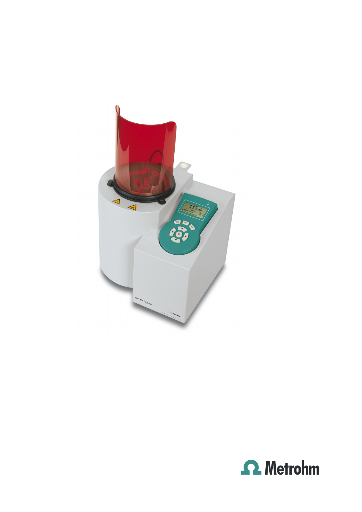
909 UV Digester
8.909.8001EN
Manual
01.2013 ebe
Page 4

Teachware
Metrohm AG
CH-9100 Herisau
teachware@metrohm.com
This documentation is protected by copyright. All rights reserved.
Although all the information given in this documentation has been
checked with great care, errors cannot be entirely excluded. Should you
notice any mistakes please send us your comments using the address
given above.
Documentation in additional languages can be found on
http://documents.metrohm.com.
Page 5

■■■■■■■■■■■■■■■■■■■■■■
Table of contents
1 Introduction 1
1.1 Instrument description ......................................................... 1
1.1.1 Supply voltage ......................................................................... 1
1.1.2 Intended use ........................................................................... 1
1.2 Function description ............................................................. 2
1.3 About the documentation ................................................... 3
1.3.1 Symbols and conventions ........................................................ 3
1.4 Safety instructions ................................................................ 4
1.4.1 General notes on safety ........................................................... 4
1.4.2 Electrical safety ........................................................................ 4
1.4.3 Personnel safety ...................................................................... 5
1.4.4 Flammable solvents and chemicals ........................................... 6
1.4.5 Recycling and disposal ............................................................. 6
Table of contents
2 Overview of the instrument 7
3 Installation 9
3.1 Setting up the instrument .................................................... 9
3.1.1 Packaging ................................................................................ 9
3.1.2 Checks .................................................................................... 9
3.1.3 Location .................................................................................. 9
3.2 Inserting the UV lamp .......................................................... 9
3.3 Mounting the UV protective shield ................................... 11
3.4 Preparing and connecting the temperature sensor ........ 14
3.5 Inserting the sample holder ............................................... 17
3.6 Connecting the power supply cable ................................. 18
4 Operation 20
4.1 Switching the instrument on and off ............................... 20
4.2 Dialog window overview ................................................... 20
4.2.1 Main dialog ........................................................................... 20
4.2.2 "Parameters" dialog ............................................................... 20
4.2.3 "Lamp info" dialog ................................................................ 21
4.2.4 "Lamp setup" dialog .............................................................. 21
909 UV Digester
4.3 The keypad .......................................................................... 23
4.3.1 The key functions .................................................................. 23
4.4 The display .......................................................................... 24
4.4.1 Display elements .................................................................... 24
4.4.2 Status display ........................................................................ 25
■■■■■■■■
III
Page 6

Table of contents
■■■■■■■■■■■■■■■■■■■■■■
4.5 Changing numerical values ................................................ 25
5 Carrying out sample digestion 26
6 Application examples 31
7 Operation and maintenance 33
7.1 General ................................................................................ 33
7.2 Care ...................................................................................... 34
7.2.1 Maintaining and replacing the UV lamp ................................. 34
7.2.2 Clearing a jammed fan ........................................................... 35
7.2.3 Cleaning sample glasses ........................................................ 36
7.3 Quality Management and qualification with
Metrohm ............................................................................. 36
8 Troubleshooting 37
8.1 Error messages ................................................................... 37
8.2 Additional faults and their remedy ................................... 38
9 Technical specifications 39
9.1 Radiating ............................................................................. 39
9.2 Mercury vapor lamp ........................................................... 39
9.3 Temperature measuring input ........................................... 39
9.4 Power connection ............................................................... 40
9.4.1 220 - 240 V power connection .............................................. 40
9.4.2 100 - 127 V power connection with a transformer ................ 40
9.5 Safety specifications ........................................................... 40
9.6 Electromagnetic compatibility (EMC) ................................ 41
9.7 Ambient temperature ......................................................... 41
9.8 Reference conditions .......................................................... 42
9.9 Dimensions .......................................................................... 42
10 Warranty (guarantee) 43
11 Accessories 45
11.1 Scope of delivery ................................................................ 45
11.2 Optional accessories ........................................................... 49
■■■■■■■■
IV
Index 50
909 UV Digester
Page 7

■■■■■■■■■■■■■■■■■■■■■■
Table of figures
Figure 1 UV lamp spectrum ............................................................................. 2
Figure 2 Front 909 UV Digester ....................................................................... 7
Figure 3 Rear 909 UV Digester ........................................................................ 8
Figure 4 Guiding the UV lamp downward into the wet end ........................... 10
Figure 5 Installing the UV lamp in the wet end .............................................. 11
Figure 6 Removing the stop .......................................................................... 11
Figure 7 Positioning the UV protective shield over the wet end ..................... 12
Figure 8 Positioning the stop over the threaded hole ..................................... 13
Figure 9 Screwing the stop in place ............................................................... 13
Figure 10 Removing the temperature sensor from the storage vessel .............. 14
Figure 11 Removing the spacer from the temperature sensor .......................... 14
Figure 12 Removing the SGJ sleeve from the temperature sensor .................... 14
Figure 13 Attaching the thermometer plug on the temperature sensor ........... 15
Figure 14 Attaching the spacer to the temperature sensor .............................. 15
Figure 15 Inserting the storage vessel for the temperature sensor into the
holder ............................................................................................. 16
Figure 16 Connecting a temperature sensor .................................................... 16
Figure 17 Guiding the sample holder into the wet end .................................... 17
Figure 18 Positioning the cylindrical guide for the sample holder ..................... 18
Figure 19 Inserting the temperature sensor at sample position 6 ..................... 18
Figure 20 Keypad for the operating unit .......................................................... 23
Figure 21 Main dialog - Display elements ........................................................ 24
Table of figures
909 UV Digester
■■■■■■■■
V
Page 8

Page 9

■■■■■■■■■■■■■■■■■■■■■■
1 Introduction
1.1 Instrument description
The 909 UV Digester is used for the digestion of aqueous samples moderately loaded with organic material. Its primary use is sample preparation
for analyses in voltammetry, ion chromatography, AAS and ICP-AES. The
digestion of samples is based on the photolytic generation of hydroxyl
radicals, whose formation is initiated by a hydrogen peroxide radical initiator. The hydroxyl radicals immediately react with the organic compounds
and work to break them down. The temperature and time for digestion
can be entered conveniently using the operating unit. The temperature is
controlled automatically using air cooling and the UV lamp's emitter
power (medium pressure mercury lamp), which is regulated between
100% and 50% as needed.
The 909 UV Digester combines the wet end and control unit in one housing. The UV lamp is located in the center of the wet end. The sample vessels are inserted in the sample holder encircling the UV lamp. The fan for
air cooling is located in the lower portion of the wet end. The control unit
consists of the operating unit and all of the electronics including the electronic ballast for regulating the UV lamp. The 909 UV Digester is used as a
standalone instrument.
1 Introduction
1.1.1 Supply voltage
The 909 UV Digester can be operated only with a supply voltage of 220 to
240 V. Therefore, for a supply voltage of 100 to 120 V, a transformer has
to be connected between the power and the instrument. You can find
details on the transformer's specifications in Chapter Technical specifica-
tions, page 39.
1.1.2 Intended use
The 909 UV Digester is a sample preparation instrument that can be used
in analytical laboratories for preparing samples for the following analysis
processes:
■ Voltammetry
■ Ion chromatography
■ AAS
■ ICP-AES
Chemicals and flammable substances can be used as a sample additive or
auxiliary reagent in this instrument. Usage of the 909 UV Digester therefore requires the user to have basic knowledge and experience in handling
toxic and caustic substances. Knowledge with respect to the application
909 UV Digester
■■■■■■■■
1
Page 10
1.2 Function description
100
90
80
70
60
50
40
30
20
10
0
200 300 400 500
600
700
Intensity [%]
Wavelength [nm]
1 2
of the fire prevention measures prescribed for laboratories is also mandatory.
1.2 Function description
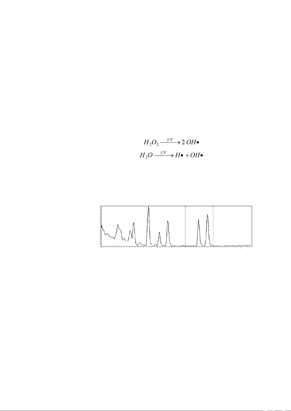
Through the effects of UV radiation, dissolved organic matter that disrupts
the trace analysis of heavy metals is decomposed. However, the UV radiation itself does not cause the digestion of the organic sample components; rather, hydroxyl radicals that form break down the organic matter.
Hydroxyl radicals are initially formed from the added hydrogen peroxide
that functions as the initiator for the radical chain reaction. Subsequently,
additional hydroxyl radicals are generated from the water if the temperature is high enough. Depending on the sample matrix, it may be necessary
to add more H2O2 during digestion.
■■■■■■■■■■■■■■■■■■■■■■
Spectrum of the UV lamp
The following figure shows a typical spectrum for the UV lamp. Certain
deviations from this spectrum are possible; this can be traced back to production-related factors.
Figure 1
UV lamp spectrum
■■■■■■■■
2
909 UV Digester
Page 11
■■■■■■■■■■■■■■■■■■■■■■
UV
1.3 About the documentation
Caution
Please read through this documentation carefully before putting the
instrument into operation. The documentation contains information
and warnings which the user must follow in order to ensure safe operation of the instrument.
1.3.1 Symbols and conventions
The following symbols and formatting may appear in this documentation:
Cross-reference to figure legend
The first number refers to the figure number, the second to the instrument part in the figure.
1 Introduction
Instruction step
Carry out these steps in the sequence shown.
Method Dialog text, parameter in the software
File ▶ New Menu or menu item
[Continue] Button or key
Warning
This symbol draws attention to a possible life-threatening hazard or risk of injury.
Warning
This symbol draws attention to a possible hazard due
to electrical current.
Warning
This symbol draws attention to a possible hazard due
to heat or hot instrument parts.
Warning
This symbol draws attention to hazardous UV radiation.
Warning
This symbol draws attention to a possible biological
hazard.
909 UV Digester
■■■■■■■■
3
Page 12
1.4 Safety instructions
1.4 Safety instructions
1.4.1 General notes on safety
Warning
This instrument may only be operated in accordance with the specifications in this documentation.
This instrument has left the factory in a flawless state in terms of technical
safety. To maintain this state and ensure non-hazardous operation of the
instrument, the following instructions must be observed carefully.
■■■■■■■■■■■■■■■■■■■■■■
Caution
This symbol draws attention to possible damage to
instruments or instrument parts.
Note
This symbol marks additional information and tips.
1.4.2 Electrical safety
The electrical safety when working with the instrument is ensured as part
of the international standard IEC 61010.
Only personnel qualified by Metrohm are authorized to carry out service
work on electronic components.
Never open the housing of the instrument. The instrument could be
damaged by this. There is also a risk of serious injury if live components
are touched.
There are no parts inside the housing which can be serviced or replaced
by the user.
Warning
Warning
■■■■■■■■
4
909 UV Digester
Page 13
■■■■■■■■■■■■■■■■■■■■■■
UV
Warning
1 Introduction
Supply voltage
Warning
An incorrect supply voltage can damage the instrument.
Operate this instrument only with a supply voltage specified for it (refer
to the rear of the instrument). Use a transformer if necessary (for specifications for the transformer see Chapter 9.4.2, page 40).
Protection against electrostatic charges
Warning
Electronic components are sensitive to electrostatic charges and can be
destroyed by discharges.
Do not fail to pull the mains cable out of the mains connection socket
before you set up or disconnect electrical plug connections at the rear
of the instrument.
1.4.3 Personnel safety
Hazardous chemical substances
Chemical substances can cause chemical burns and skin damage.
Correctly install the UV protective shield and wear protective glasses,
protective gloves and work clothes appropriate for laboratory work
when operating the 909 UV Digester.
Harmful UV radiation
UV radiation damages the eyes.
Protect your eyes from UV light during operation. Correctly install the
UV protective shield and wear UV protective glasses.
The 909 UV Digester has to be operated in a closed fume cupboard or
in a closed laboratory and may be operated only by trained personnel.
Warning
909 UV Digester
Attach the supplied UV warning shield included in the accessories to
the fume cupboard.
■■■■■■■■
5
Page 14
1.4 Safety instructions
■■■■■■■■■■■■■■■■■■■■■■
Warning
Escaping ozone
Ozone can damage mucous membranes.
The 909 UV Digester has to be operated in a closed fume cupboard or
in a closed laboratory and may be operated only by trained personnel.
Warning
Hot surfaces
The UV lamp, sample vessels and sample holder become very hot during operation. The UV lamp can reach a temperature of 900 °C.
Skin contact during and immediately after a radiating procedure will
cause burns.
Avoid skin contact until the instrument is completely cool or wear heatinsulated gloves if necessary.
1.4.4 Flammable solvents and chemicals
Warning
All relevant safety measures are to be observed when working with
flammable solvents and chemicals.
■ Set the instrument up in a closed fume cupboard.
■ Keep all sources of flame far from the workplace.
■ Clean up spilled liquids and solids immediately.
■ Follow the safety instructions of the chemical manufacturer.
1.4.5 Recycling and disposal
This product is covered by European Directive 2002/96/EC, WEEE – Waste
from Electrical and Electronic Equipment.
The correct disposal of your old equipment will help to prevent negative
effects on the environment and public health.
More details about the disposal of your old equipment can be obtained
from your local authorities, from waste disposal companies or from your
local dealer.
■■■■■■■■
6
909 UV Digester
Page 15
■■■■■■■■■■■■■■■■■■■■■■
1
2
3
4
5
6
7
8
9
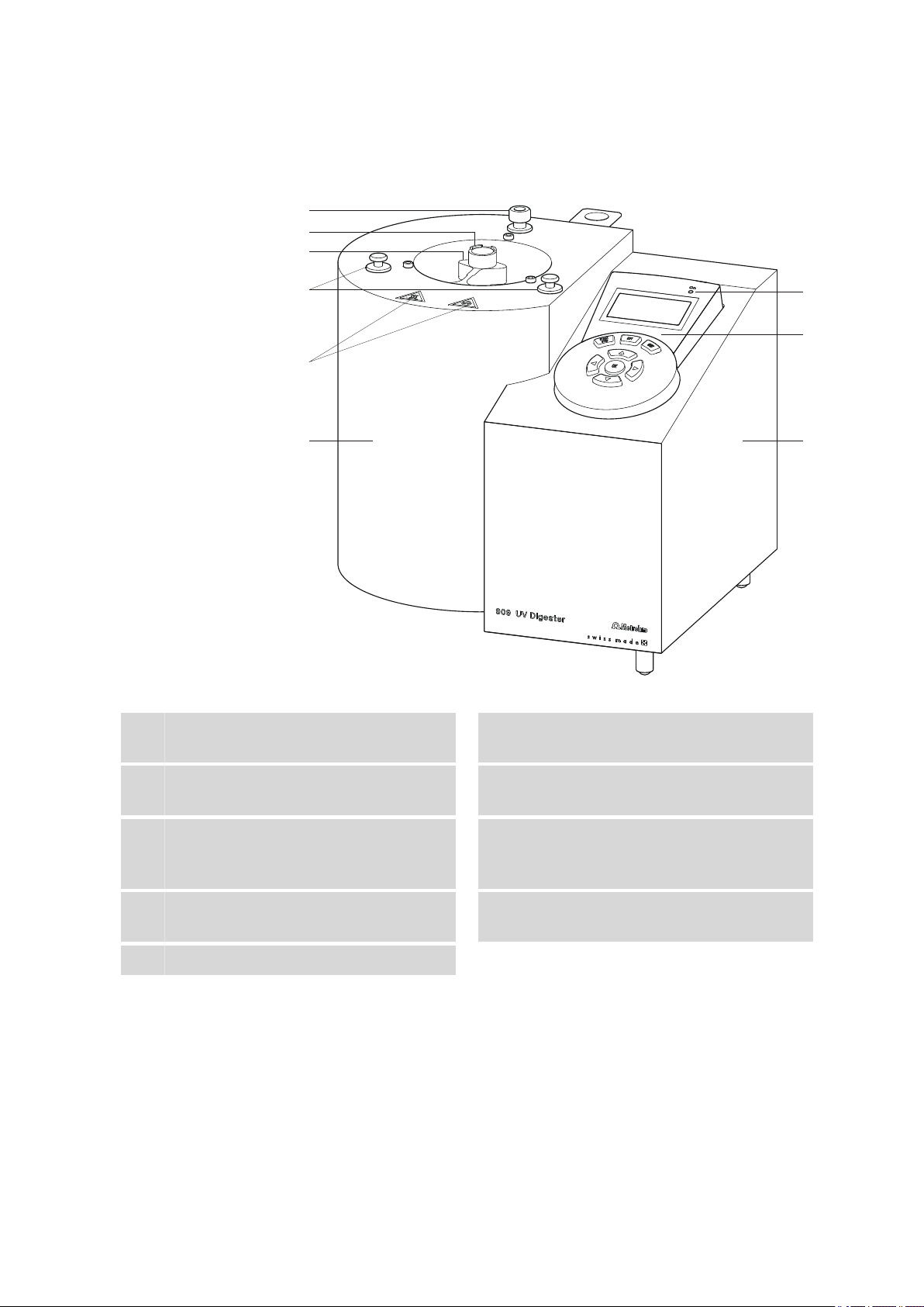
2 Overview of the instrument
2 Overview of the instrument
Figure 2 Front 909 UV Digester
Wet end
1
Stops
3
For positioning the UV protective shield.
Holder
5
For inserting the sample holder.
"On" LED
7
Lights up if the instrument is switched on.
Control unit
9
Warning symbols
2
"UV radiation" and "Hot surfaces".
Lamp holder
4
With upper lamp socket.
Stop
6
With hex socket head screw, for mounting
the UV protective shield.
Operating unit
8
With keyboard and display.
909 UV Digester
■■■■■■■■
7
Page 16
■■■■■■■■■■■■■■■■■■■■■■
1
2
3
4
5
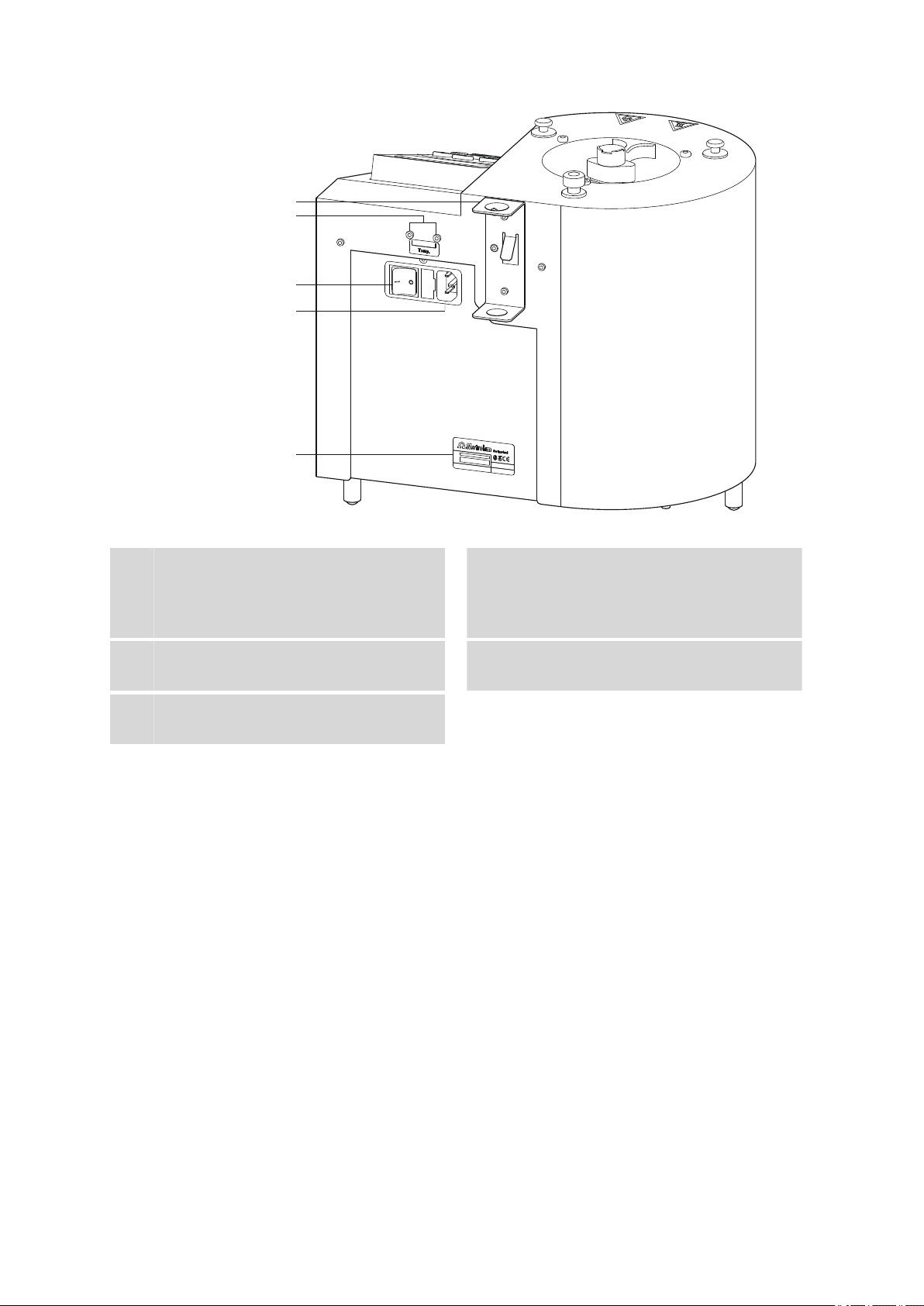
Figure 3 Rear 909 UV Digester
Holder
1
For storage vessel for temperature sensor.
Power switch
3
For switching the instrument on and off.
Type plate
5
Contains the serial number.
Temperature sensor connection
2
(Temp.)
For connecting the Pt1000 temperature sensor. Two B sockets, 2 mm.
Power socket
4
■■■■■■■■
8
909 UV Digester
Page 17

■■■■■■■■■■■■■■■■■■■■■■
3 Installation
3.1 Setting up the instrument
3.1.1 Packaging
The instrument is supplied in highly protective special packaging together
with the separately packed accessories. Keep this packaging, as only this
ensures safe transportation of the instrument.
3.1.2 Checks
Immediately after receipt, check whether the shipment has arrived complete and without damage by comparing it with the delivery note.
3.1.3 Location
The instrument has been developed for operation indoors and may not be
used in explosive environments.
3 Installation
In the wet end of the 909 UV Digester, ozone from the air is released due
to the UV radiation. Set up the instrument in a fume cupboard or closed
laboratory at a location in the laboratory that is suitable for operation and
free of vibrations. The location should be protected from corrosive atmospheres and contamination from chemicals.
The instrument should be protected against excessive temperature fluctuations and direct sunlight.
3.2 Inserting the UV lamp
The UV lamp (6.2804.090) is included in the scope of delivery for the 909
UV Digester.
Caution
Spots on the quartz tube
Spots will be burned into the quartz glass if you touch the UV lamp's
quartz tube with bare hands and put it into operation without cleaning
it first. This lowers the power of the UV lamp.
909 UV Digester
Always use the cotton glove included with the UV lamp to install the
lamp and only touch the UV lamp at the two flattened ends. Remove
any grease spots or dust particles stuck to the quartz tube before starting the UV lamp.
■■■■■■■■
9
Page 18
3.2 Inserting the UV lamp
■■■■■■■■■■■■■■■■■■■■■■
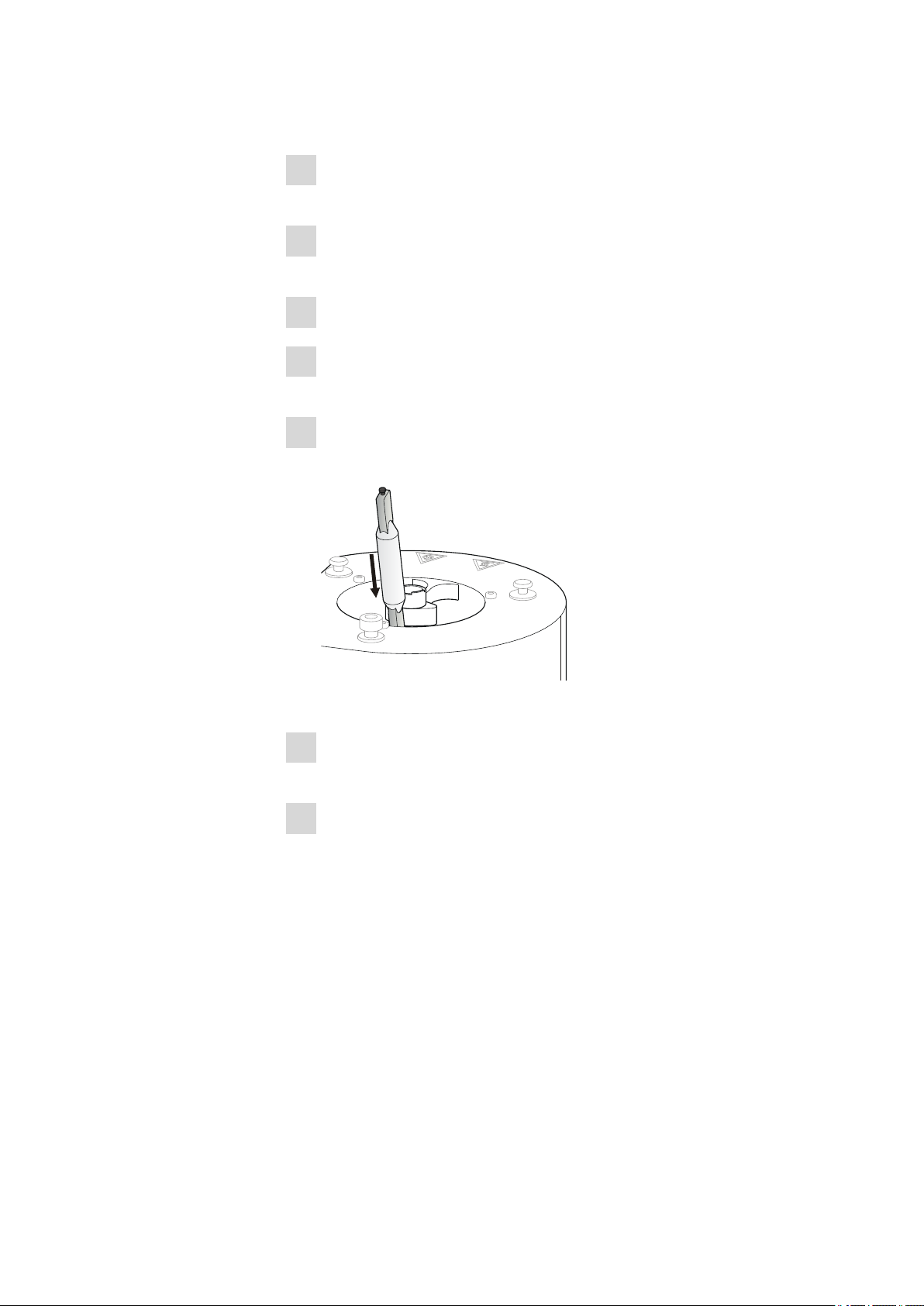
Proceed as follows to insert the UV lamp:
Ensure that the power for the 909 UV Digester has been disconnec-
1
ted.
Remove the sample holder from the wet end if it has already been
2
inserted.
Put on the cotton glove included with the UV lamp.
3
Wipe off any spots on the quartz tube using a clean towel wetted
4
with pure alcohol.
Hold the UV lamp by one of the two flattened ends and guide it
5
downward into the wet end.
Figure 4 Guiding the UV lamp downward into the wet end
Insert the metal contact projecting on the lower end of the UV lamp
6
into the lower lamp socket and press it down gently.
While holding the UV lamp down, click the metal contact projecting
7
upwards into the upper lamp socket.
■■■■■■■■
10
909 UV Digester
Page 19

■■■■■■■■■■■■■■■■■■■■■■
1
2
3 Installation
Figure 5 Installing the UV lamp in the wet end
3.3 Mounting the UV protective shield
A UV protective shield (6.2745.100) pre-installed on a metal ring is included in the scope of delivery for the 909 UV Digester.
Proceed as follows:
Using the hex key (6.2621.100), unscrew the stop's hex socket head
1
screw (2-6) on the back of the housing and remove the stop.
Keep the stop with the hex socket head screw in reach. It will have
to be screwed back in place on the housing afterwards.
Figure 6 Removing the stop
Place the UV protective shield over the wet end's opening so that the
2
metal ring rests on the two front stops (2-3).
909 UV Digester
■■■■■■■■
11
Page 20

3.3 Mounting the UV protective shield
■■■■■■■■■■■■■■■■■■■■■■
Ensure that the UV protective shield is positioned towards the front.
Figure 7 Positioning the UV protective shield over the wet end
Place the stop removed earlier over the threaded hole in the back on
3
the housing.
Ensure that the metal ring for the UV protective shield is located in
the slot between the lower and upper part of the stop.
■■■■■■■■
12
909 UV Digester
Page 21

■■■■■■■■■■■■■■■■■■■■■■
Figure 8 Positioning the stop over the threaded hole
Screw the stop back in place on the housing with the hex socket
4
head screw.
3 Installation
909 UV Digester
Figure 9 Screwing the stop in place
Check whether the UV protective shield can be turned back all the
way to the stop (2-6) on both sides.
■■■■■■■■
13
Page 22

3.4 Preparing and connecting the temperature sensor
■■■■■■■■■■■■■■■■■■■■■■
3.4 Preparing and connecting the temperature sensor
The temperature sensor (6.1110.010) is included in the scope of delivery
for the 909 UV Digester.
Preparing
Proceed as follows:
Remove the temperature sensor from the storage vessel.
1
Figure 10 Removing the temperature sensor from the storage ves-
sel
Remove the spacer in the lower part of the glass tube.
2
Figure 11 Removing the spacer from the temperature sensor
Keep the spacer in reach. It will have to be attached back on the
glass tube afterwards.
Remove the SGJ sleeve.
3
Figure 12 Removing the SGJ sleeve from the temperature sensor
Guide the thermometer plug (6.1446.190) over the temperature sen-
4
sor from the bottom until it is flush with the head of the temperature
sensor.
■■■■■■■■
14
909 UV Digester
Page 23

■■■■■■■■■■■■■■■■■■■■■■
Figure 13 Attaching the thermometer plug on the temperature
sensor
Insert the spacer back into the notch in the glass tube.
5
Figure 14 Attaching the spacer to the temperature sensor
The spacer ensures that the temperature sensor is positioned in the
middle of the sample, thereby ensuring optimal temperature measurement.
3 Installation
Inserting the storage vessel for the temperature sensor
Insert the storage vessel (6.2008.040) included in the scope of deliv-
1
ery in the holder (3-1) on the rear of the instrument.
909 UV Digester
■■■■■■■■
15
Page 24

3.4 Preparing and connecting the temperature sensor
■■■■■■■■■■■■■■■■■■■■■■
Figure 15 Inserting the storage vessel for the temperature sensor
into the holder
For storing the temperature sensor between digestion processes.
Insert the temperature sensor equipped with the temperature plug
2
and spacer into the storage vessel.
Connecting
Proceed as follows:
Insert the plugs for the temperature sensor into the Temp. sockets.
1
■■■■■■■■
16
Figure 16 Connecting a temperature sensor
909 UV Digester
Page 25

■■■■■■■■■■■■■■■■■■■■■■
12
1
Note
Always insert the red plug into the red socket. This is the only way
that shielding against electrical interference can be ensured.
3.5 Inserting the sample holder
The sample holder has to be fully filled to ensure uniform temperature distribution in the samples (see "Preparing samples", page 26).
Proceed as follows:
Guide the sample holder on the mounting bracket into the wet end
1
so that the slot between sample positions 1 and 12 ends up located
at the front at the lamp holder (2-4).
3 Installation
909 UV Digester
Figure 17 Guiding the sample holder into the wet end
Ensure that the cylindrical guide on the bottom of the sample holder's mounting bracket clicks in place in the holder (2-5).
■■■■■■■■
17
Page 26

3.6 Connecting the power supply cable
12
1
6
2
■■■■■■■■■■■■■■■■■■■■■■
Figure 18 Positioning the cylindrical guide for the sample holder
Always insert the temperature sensor into the sample vessel filled
with sample at Position 6 of the sample holder.
Figure 19 Inserting the temperature sensor at sample position 6
3.6 Connecting the power supply cable
Warning
An incorrect supply voltage can damage the instrument.
The 909 UV Digester is designed for 220 to 240 V. You need to use a
transformer if your power supply provides 100 to 120 V. You can find
the specification for the transformer in Chapter 9.4.2, page 40.
Proceed as follows to connect the instrument to the power supply.
■■■■■■■■
18
909 UV Digester
Page 27

■■■■■■■■■■■■■■■■■■■■■■
Without a transformer
Connect the UV Digester to the power supply using the power sup-
1
ply cable included in the scope of delivery.
With a transformer
Connect the transformer to the power supply.
1
Connect the UV Digester to the transformer using the power supply
2
cable included in the scope of delivery.
3 Installation
909 UV Digester
■■■■■■■■
19
Page 28

4.1 Switching the instrument on and off
4 Operation
4.1 Switching the instrument on and off
The toggle switch for switching on and off is located on the rear of the
instrument (3-3).
After switching on the instrument, the main dialog is displayed with the
most recently configured parameters.
When starting for the first time, the standard parameters Sample Temp.
= 90 °C and Rad. Time = 90 min appear.
4.2 Dialog window overview
The following four dialogs are available for operating the 909 UV Digester:
■■■■■■■■■■■■■■■■■■■■■■
4.2.1 Main dialog
The main dialog is displayed after switching on the 909 UV Digester.
The following information is displayed:
■ The temperature currently being measured in the sample (Curr.
Temp.).
■ The sample setpoint temperature configured in the Parameters dialog
(Set Temp.).
4.2.2 "Parameters" dialog
■■■■■■■■
20
You can open the Parameters dialog from the main dialog by pressing
the [SET] key.
You must configure the following parameters in this dialog:
909 UV Digester
Page 29

■■■■■■■■■■■■■■■■■■■■■■
Sample Temp.
Rad. Time
4 Operation
■ The sample setpoint temperature (Sample Temp.).
■ The radiating time (Rad. Time).
Setpoint temperature for the samples.
Input range 80 - 100 °C (Increment: 1)
Default value 90 °C
Radiating time for the samples.
Input range 1 - 999 min (Increment: 1)
Default value 90 min
Note
■ The configured parameters can be modified during digestion.
■ The configured parameters remain stored in the instrument after it is
switched off.
4.2.3 "Lamp info" dialog
You can open the Lamp info dialog from the main dialog by pressing the
[OK] key twice.
The following information is displayed:
■ The cumulative number of operating hours for the current UV lamp in
use since the last replacement (Hours).
■ The number of times the current UV lamp in use has been switched on
since the last replacement (Ignitions).
4.2.4 "Lamp setup" dialog
909 UV Digester
■■■■■■■■
21
Page 30

4.2 Dialog window overview
Replace after
Reset counters
■■■■■■■■■■■■■■■■■■■■■■
You can open the Lamp setup dialog by pressing and holding the [SET]
key while switching on the 909 UV Digester.
You have to edit the following parameters if you have inserted a new UV
lamp:
■ Reset the counters back to zero for the cumulative operating hours and
number of times the lamp has been switched on (Reset Counters).
■ Configure the number of operating hours for the new UV lamp until
the next replacement (Replace after).
Maximum number of operating hours for the UV lamp until the next
replacement.
Input range 0 - 1000 h (Increment: 1)
Default value 750 h
We recommend replacing the UV lamp after 750 h
of operating time.
For resetting both counters for cumulative operating hours and the number of times the UV lamp has been switched on (ignitions) to 0.
Confirming with [OK] triggers the following confirmation prompt:
Selection [OK] | [QUIT]
[OK]
Both counters are reset to 0.
[QUIT]
Both counters remain at their current values.
Caution
The counters cannot be reset during the ongoing service life of a UV
lamp currently in use.
■■■■■■■■
22
909 UV Digester
Page 31

■■■■■■■■■■■■■■■■■■■■■■
4.3 The keypad
Below you will find an overview of the operating unit's keypad and the
functions of the keys in the various dialog windows.
4 Operation
Figure 20 Keypad for the operating unit
4.3.1 The key functions
Key Main dialog Parameters Lamp info Lamp setup
[START
STOP]
[SET] Open the Parameters
[QUIT] Acknowledge an error
[OK] Open the Lamp info
■ Start lamp radiat-
ing.
■ Stop lamp radiat-
ing.
dialog.
message.
dialog.
– – –
– – –
Depending on the cur-
Leave the dialog. Depending on the cur-
sor position:
■ Discard a change.
■ Leave the dialog.
Depending on the cursor position:
■ Save a change and
switch to the next
parameter.
■ Save a change and
Display the number of
cumulative operating
hours and times the
lamp has been
switched on (ignitions).
leave the dialog.
sor position:
■ Discard a change.
■ Leave the dialog.
Depending on the cursor position:
■ Save a change.
■ Trigger the confir-
mation prompt for
resetting the counters.
■ Reset the counters
to zero.
909 UV Digester
■■■■■■■■
23
Page 32

4.4 The display
T
1
2
3
4
Key Main dialog Parameters Lamp info Lamp setup
■■■■■■■■■■■■■■■■■■■■■■
[▲] Increase the display's
contrast.
[▼] Decrease the display's
contrast.
[▶] – Depending on the cur-
[◀] – Depending on the cur-
Depending on the cursor position:
■ Go up one line.
■ Page up by one
value list.
Depending on the cursor position:
■ Go down one line.
■ Page down by one
value list.
sor position:
■ Move the cursor to
the value range.
■ Move the cursor
one position to the
right.
sor position:
■ Move the cursor to
the value range.
■ Move the cursor
one position to the
left.
Go up one line. Depending on the cur-
sor position:
■ Go up one line.
■ Page up by one
value list.
Go down one line. Depending on the cur-
sor position:
■ Go down one line.
■ Page down by one
value list.
– Depending on the cur-
sor position:
■ Move the cursor to
the value range.
■ Move the cursor
one position to the
right.
– Depending on the cur-
sor position:
■ Move the cursor to
the value range.
■ Move the cursor
one position to the
left.
4.4 The display
4.4.1 Display elements
Figure 21
Radiating time
1
Shows the remaining radiating time since
the UV lamp was started.
Temperature display
3
Shows the configured sample setpoint temperature.
Main dialog - Display elements
Temperature display
2
Shows the current temperature measured in
the sample.
Status line
4
Contains the current status or an error message along with the respective symbol.
■■■■■■■■
24
909 UV Digester
Page 33

■■■■■■■■■■■■■■■■■■■■■■
4.4.2 Status display
The following symbols and the respective text can be displayed in the status line:
Symbol Text Meaning
4 Operation
Heating The samples are being heated.
Temp. reached The configured sample setpoint
temperature has been reached.
Lamp cooling The samples are being cooled.
Various error messages
4.5 Changing numerical values
The various parameters can be selected using the arrow keys [▼] and [▲].
The colors on the current line are reversed.
Change parameters as follows:
Use the arrow keys [▶] or [◀] to select a numerical value.
1
The selected digit is displayed in black on white. The colors for the
rest of the line remain reversed.
Change the digit using the arrow keys [▲] or [▼].
2
Select the next digit and change it, etc.
3
Apply the modified value with the [OK] key.
4
see Chapter 8.1, page 37.
909 UV Digester
Press [QUIT] if the previous value is to be restored.
■■■■■■■■
25
Page 34

5 Carrying out sample digestion
The following steps can be used as a model describing the steps for sample digestion using the 909 UV Digester. You can find additional useful
tips on analysis methods in the Application Bulletins and Application Notes
listed in Chapter 6, page 31.
Preparing the 909 UV Digester
Installing the 909 UV Digester (see Chapter 3, page 9).
1
Set the sample setpoint temperature to the desired value (see "Sam-
2
ple Temp.", page 21).
Set the radiating time to the desired period (see "Rad. Time", page
3
21).
■■■■■■■■■■■■■■■■■■■■■■
Preparing samples
Warning
Samples with increased organic load
Overflowing chemical substances can cause chemical burns and skin
damage. They can also damage the instrument.
Ensure that the sample vessel with the temperature sensor has the
same sample as the rest of the sample vessels. Otherwise the PTFE stoppers can be pushed out during heating and the sample can overflow.
Wear protective glasses, protective gloves and work clothes suitable for
laboratory work.
Add, at most, 12 mL of sample to be broken down per sample ves-
1
sel.
■■■■■■■■
26
909 UV Digester
Page 35

■■■■■■■■■■■■■■■■■■■■■■
5 Carrying out sample digestion
Note
Use the provided sample vessels
Only use the sample vessels made of quartz glass (6.2414.000)
that have been provided. Normal reagent glasses do not let UV
radiation through and do not ensure complete digestion. Clean
the sample glasses before use as described in Chapter 7.2.3, page
36.
Add nitric acid (w(HNO3) = 65%, for trace analysis) and hydrogen
2
peroxide (w(H2O2) = 30%, for trace analysis).
Samples with a low organic load are offset with the following
reagent concentrations:
■ 0.01 mL HNO
■ 0.05 mL H
(w(HNO3) = 65%, for trace analysis)
3
(w(H2O2) = 30%, for trace analysis)
2O2
The sample volume, the volume of the reagents and the digestion
parameters must be adjusted accordingly for samples with increased
organic load.
Place the PTFE stopper (6.1446.100) on the sample vessels. Leave the
3
sample vessel at Position 6 free for measuring the temperature.
Insert the sample holder into the wet end (see Chapter 3.5, page
4
17).
Note
Fully filled sample holder
Only a fully filled sample holder enables even temperature distribution to the samples. If you use fewer than twelve samples, fill the
remaining sample vessels with distilled water.
909 UV Digester
Insert the temperature sensor (6.1110.010) with attached thermom-
5
eter plug (6.1446.190) and spacer into the sample vessel at Position
6 and press it down.
■■■■■■■■
27
Page 36

■■■■■■■■■■■■■■■■■■■■■■
UV
Warning
Starting sample digestion
1
Hazardous UV radiation
UV radiation damages the eyes.
Protect your eyes from UV light during operation. Position the UV
protective shield on the front of the instrument and wear UV protective glasses.
The 909 UV Digester has to be operated in a closed fume cupboard or in a closed laboratory and may be operated only by
trained personnel.
Press the [START / STOP] key.
The UV lamp is switched on. You can track the current temperature
and time until the end of radiating on the display.
You can top off the hydrogen peroxide (w(H2O2) = 30%, for trace
analysis) as needed during radiating. This may be necessary for samples with a larger organic load.
Note
The digestion temperature and radiating time can be modified during the digestion process. Proceed as described in Chapter 4.2.2,
page 20 as needed.
Procedure after sample digestion
Sample digestion ends and the UV lamp is switched off automatically once
the configured radiating time elapses. The fan cools the samples for 10
min.
Proceed as follows after sample digestion:
Wait for the samples to cool (the fan switches off after 10 min).
1
Remove the sample holder with the samples from the wet end.
2
■■■■■■■■
28
909 UV Digester
Page 37

■■■■■■■■■■■■■■■■■■■■■■
5 Carrying out sample digestion
Note
Leave the PTFE stoppers on the sample vessels until you are ready
to continue using the samples.
Switch off the 909 UV Digester or carry out additional sample diges-
3
tion processes.
Canceling sample digestion
Proceed as follows if you would like to stop a sample digestion process
before the radiating time has elapsed:
Press the [START / STOP] key.
1
The UV lamp is switched off.
Wait for the samples to cool (the fan switches off after 10 min).
2
Remove the sample holder with the samples from the wet end.
3
Switch off the 909 UV Digester or carry out additional sample diges-
4
tion processes.
Note
Opened samples smell like ammonia or fish (amine)
If an open sample smells like ammonia or fish, you need to increase the
amount of acid and/or H2O2 being added.
909 UV Digester
■■■■■■■■
29
Page 38

■■■■■■■■■■■■■■■■■■■■■■
Note
Nitrite interference
Nitrite forms from the effects of UV radiation on nitrate. It is voltammetrically active and shows a wide peak at –1.2 V. This peak can overlap with signals from metals such as zinc, thereby causing interference.
You can prevent this reaction in two ways:
■ Add acid to the sample solutions using HCl instead of HNO
■ Reduce the nitrite using sulfamic acid: add 0.025 mL (β(sulfamic
.
3
acid) = 40 g/L) to 10 mL of open, hot sample solution.
■■■■■■■■
30
909 UV Digester
Page 39

■■■■■■■■■■■■■■■■■■■■■■
6 Application examples
You can find useful examples of analysis methods in the Application Bulletins and Application Notes below.
Table 1 Application Bulletins
6 Application examples
Application
Bulletin No.
74 Tl, Sb, Bi, Fe, Cu, V
96 Hg
116 Cr
117 Se
123 Fe, Mn
131 Al
146 Mo
176 Sn, Pb
186 Al
207 Ag
220 Pt, Rh
226 As
231 Zn, Cd, Pb, Cu, Tl, Ni, Co
Analytes
909 UV Digester
242 W
243 Cr
266 Ti, U
Table 2 Application Notes
Application
Note No.
V-83 Zinc, cadmium, lead and copper in waste water after
V-84 Total chromium in waste water after UV digestion
V-89 Mercury in waste water
V-92 Nickel in white wine
Title
UV digestion
■■■■■■■■
31
Page 40

■■■■■■■■■■■■■■■■■■■■■■
Application
Title
Note No.
V-93 Zinc, cadmium, lead and copper in red wine
V-94 Rhodium and platinum in red wine
V-96 Platinum in urine
V-106 Nickel and cobalt in waste water
V-107 Tin in waste water
V-108 Thallium in waste water
V-109 Selenium in waste water
V-110 Chromium in waste water
V-120 Nickel in glycol after UV digestion
V-121 Determination of total iron in waste water of UV
digestion
V-176 Total selenium in tap water after reduction of sele-
nium(VI) to selenium(IV) by means of UV Digester
V-201 Nickel and cobalt in red wine
■■■■■■■■
32
909 UV Digester
Page 41

■■■■■■■■■■■■■■■■■■■■■■
7 Operation and maintenance
Warning
Never open the housing of the instrument. The instrument could be
damaged by this. There is also a risk of serious injury if live components
are touched.
There are no parts inside the housing which can be serviced or replaced
by the user.
7.1 General
The 909 UV Digester requires appropriate care. Excess contamination of
the instrument may result in functional disruptions and a reduction in the
lifetime of the sturdy mechanics and electronics of the instrument.
7 Operation and maintenance
Severe contamination can also have an influence on sample digestion.
Regular cleaning of exposed parts can prevent this to a large extent.
Spilled chemicals and solvents must be removed immediately. In particular,
the power plug should be protected from contamination.
Warning
Hot surfaces
The UV lamp, sample vessels and sample holder become very hot during operation. The UV lamp can reach a temperature of 900 °C.
Skin contact during and immediately after sample digestion will cause
burns.
Only clean the wet end once it has cooled completely.
909 UV Digester
■■■■■■■■
33
Page 42

7.2 Care
7.2 Care
7.2.1 Maintaining and replacing the UV lamp
Keep the following information in mind so that the lifetime of the UV
lamp is not shortened unnecessarily:
■ Clean the UV lamp as needed using a clean towel wetted with pure
alcohol. This lets you remove particles from the quartz glass that have
not yet been burned in.
Do not touch any part of the UV lamp other than the two flattened
ends during cleaning and wear the provided cotton glove when removing or installing the lamp.
■ Avoid switching the UV lamp on and off unnecessarily. Each time the
lamp is switched on shortens its lifetime.
Removing the old UV lamp
Warning
■■■■■■■■■■■■■■■■■■■■■■
Risk of electric shock due to defective electronic components
Coming into contact with potentially defective electronic components
in the instrument could result in an electric shock.
Ensure that the instrument is unplugged before replacing the UV lamp.
Proceed as follows:
Ensure that the wet end has cooled completely.
1
Remove the sample holder from the wet end if it has been inserted.
2
Put on the glove included with the UV lamp.
3
Hold the UV lamp by the upper flattened end and gently press it
4
down.
While holding the UV lamp down, release the upper end from the
5
lamp socket.
Take the UV lamp out of the lower lamp socket and remove it from
6
the wet end.
■■■■■■■■
34
909 UV Digester
Page 43

■■■■■■■■■■■■■■■■■■■■■■
Inserting the new UV lamp
Insert the new UV lamp in accordance with Chapter 3.2, page 9.
1
Configuring parameters for the new UV lamp
Reset the counters to zero for the number of operating hours and
1
the number of times the lamp has been switched on under Lamp
setup ▶ Reset Counters (see "Reset counters", page 22).
Set the number of operating hours for the new UV lamp under
2
Lamp setup ▶ Replace after (see "Replace after", page 22).
We recommend 750 h of operating time.
7.2.2 Clearing a jammed fan
The wet end with inserted sample holder is designed so that no parts such
as PTFE stoppers can fall down. If the fan happens to get jammed anyway,
keep the following safety instruction in mind:
7 Operation and maintenance
Warning
Jammed fan
Improper work on the fan may result in injuries.
Ensure that the instrument is unplugged before clearing the jammed
fan.
Proceed as follows to remove PTFE stoppers that have fallen into the wet
end of the 909 UV Digester:
Remove the sample holder.
1
Turn the instrument upside down.
2
Gently shake the overturned instrument until the PTFE stoppers come
3
out.
909 UV Digester
■■■■■■■■
35
Page 44

7.3 Quality Management and qualification with Metrohm
■■■■■■■■■■■■■■■■■■■■■■
7.2.3 Cleaning sample glasses
Clean the sample glasses after each sample digestion process:
Proceed as follows:
Thoroughly rinse the sample glasses with double-distilled water.
1
Place the sample glasses in dilute nitric acid overnight or until their
2
next use.
Rinse the sample glasses again using double-distilled water.
3
7.3 Quality Management and qualification with
Metrohm
Quality management
Metrohm offers you comprehensive support in implementing quality management measures for instruments and software. Further information on
this can be found in the brochure "Metrohm Quality Management"
available from your local Metrohm representative.
Qualification
Please contact your local Metrohm representative for support in qualification of instruments and software. The Installation Qualification (IQ)
and Operational Qualification (OQ) are offered by Metrohm representatives as a service. They are carried out by trained employees using standardized qualification documents and in accordance with the currently
applicable requirements of the regulated industry. Further information on
this can be found in the brochure "Analytical Instrument Qualifica-
tion – Confidence in quality with IQ/OQ".
Maintenance
The electronic and mechanical functional groups of Metrohm instruments
can and should be checked by specialist personnel from Metrohm as part
of a regular preventive maintenance schedule. Please ask your local
Metrohm representative regarding the precise terms and conditions
involved in concluding a corresponding maintenance agreement. Further
information on this can be found in the brochure "Metrohm Care Con-
tracts – Protect your investment the smart way" available from your
local Metrohm representative.
■■■■■■■■
36
909 UV Digester
Page 45

■■■■■■■■■■■■■■■■■■■■■■
8 Troubleshooting
8.1 Error messages
The following error messages can occur when operating the 909 UV
Digester. Follow the instructions in the "Remedy" column and acknowledge each of the error messages by pressing the [QUIT] button.
Error message Cause Remedy
8 Troubleshooting
Max. temp. reached The temperature in the wet
end is above 105 °C. The UV
lamp is switched off automatically.
Adj. data missing
The instrument is not ready
for operation since the checksum for the calibration data
was incorrect when the
instrument was switched on.
Lamp exhausted The maximum lifetime config-
ured for the UV lamp in the
Lamp setup dialog has been
reached.
■ Check the sample matrix
and adjust it if necessary.
■ Check whether sample fluid
may have evaporated and
refill the sample if necessary.
■ Check the fan and clear it if
jammed (see Chapter 7.2.2,
page 35).
■ Contact your local Metrohm
Service department.
■ Switch the instrument off
and back on.
■ Contact your local Metrohm
Service department.
Replace the UV lamp (see
Chapter 7.2.1, page 34).
No sensor connectd The temperature sensor is
either not connected or incorrectly connected.
909 UV Digester
■ Check the temperature sen-
sor's connection.
■ Connect the temperature
sensor.
■■■■■■■■
37
Page 46

8.2 Additional faults and their remedy
Error message Cause Remedy
■■■■■■■■■■■■■■■■■■■■■■
Check Sensor/Lamp No increase in temperature is
being recorded. Possible causes:
■ The temperature sensor
has not been inserted in
the sample.
■ The sample holder includ-
ing the temperature sensor
has not been inserted into
the wet end.
■ The UV lamp is defective.
■ The electronics are defec-
tive.
Dev. busy cooling The UV lamp is too hot to be
switched on again.
Thermo switch open The instrument is defective.
Overtemperature protection is
switching off the electronic
ballast.
■ Insert the temperature sen-
sor into the sample.
■ Insert the sample holder
including the temperature
sensor into the instrument.
■ Replace the UV lamp (see
Chapter 7.2.1, page 34).
■ Contact your local Metrohm
Service department.
Wait for the end of the cooling
process (Lamp cooling status
message disappears).
Contact your local Metrohm
Service department.
8.2 Additional faults and their remedy
Problem
The configured
digestion temperature cannot be
saved.
Cause Remedy
The entered temperature is
outside the input range of
80 - 100 °C.
Set a temperature within the input range.
■■■■■■■■
38
909 UV Digester
Page 47

■■■■■■■■■■■■■■■■■■■■■■
9 Technical specifications
9.1 Radiating
9 Technical specifications
Digestion temperature
Ambient temperature
Duration 1 - 999 min
Power 600 - 300 W
Control accuracy ±3 °C
+80 - +100 °C
+5 - +35 °C
9.2 Mercury vapor lamp
UV-A radiation
UV-B radiation 280 - 315 nm
UV-C radiation 200 - 280 nm
Dimensions
Length 137 - 139 mm
Outer diameter approx. 16 mm
315 - 400 nm
35 W
40 W
70 W
9.3 Temperature measuring input
A measuring input for the Pt1000 type temperature sensor.
Accuracy
Measuring range –20.0 - +150.0 °C
909 UV Digester
±0.2 °C
(under reference conditions)
■■■■■■■■
39
Page 48

9.4 Power connection
9.4 Power connection
9.4.1 220 - 240 V power connection
Supply voltage 220 - 240 V (± 10%)
Frequency 50 - 60 Hz (± 3%)
■■■■■■■■■■■■■■■■■■■■■■
Power consump-
630 W
tion
Fuse 6.3 ATH
9.4.2 100 - 127 V power connection with a transformer
Specification for
the transformer
Input voltage 110 V typical
Output voltage 230 V typical
Frequency 50 - 60 Hz
Power > 700 VA
9.5 Safety specifications
This instrument fulfills the following electrical safety requirements:
CE marking in accordance with the EU directives:
■ 2006/95/EC (Low Voltage Directive, LVD)
■ 2004/108/EC (EMC Directive, EMC)
Federal Inspectorate for Heavy Current Installations ESTI (Accreditation
Number SCESp 033)
■ Safety mark for certification type 2 in accordance with NEV (type
testing with market monitoring, EMC conformity)
Design and testing According to EN/IEC/UL 61010-1, CSA-C22.2 No. 61010-1, protection
class I, EN/IEC 61010-2-010, EN/IEC 60529.
Safety instructions This document contains safety instructions which have to be followed
by the user in order to ensure safe operation of the instrument.
■■■■■■■■
40
909 UV Digester
Page 49

■■■■■■■■■■■■■■■■■■■■■■
9.6 Electromagnetic compatibility (EMC)
Emission
Standards fulfilled
Immunity
Standards fulfilled
■ EN/IEC 61326-1
■ EN/IEC 61000-6-3
■ EN 55011 / CISPR 11
■ EN/IEC 61000-3-2
■ EN/IEC 61000-3-3
■ EN/IEC 61326-1
■ EN/IEC 61000-6-2
■ EN/IEC 61000-4-2
■ EN/IEC 61000-4-3
■ EN/IEC 61000-4-4
■ EN/IEC 61000-4-5
■ EN/IEC 61000-4-6
■ EN/IEC 61000-4-11
■ EN/IEC 61000-4-14
■ EN/IEC 61000-4-28
9 Technical specifications
9.7 Ambient temperature
Nominal function
range
Storage –20 - +70 °C
Transport –40 - +70 °C
+10 - +35 °C
(Humidity < 80%)
(Humidity < 95%)
(Humidity < 95%)
909 UV Digester
■■■■■■■■
41
Page 50

9.8 Reference conditions
9.8 Reference conditions
■■■■■■■■■■■■■■■■■■■■■■
Ambient temperature
Supply voltage 230 V
Relative humidity ≤ 60%
Operating temperature status
Validity After adjustment
+25 °C (± 3 °C)
Instrument in operation at least 30 min
9.9 Dimensions
Width
Height 290 mm
With UV protective shield
Depth 310 mm
Weight (without
accessories)
330 mm
500 mm
10.90 kg
Material of housing
Metal, surface-treated
■■■■■■■■
42
909 UV Digester
Page 51

■■■■■■■■■■■■■■■■■■■■■■
10 Warranty (guarantee)
Metrohm guarantees that the deliveries and services it provides are free of
defects in materials, design or manufacturing.
The general warranty period is 36 months (exclusions below) from the
date of delivery or 18 months in the event of continuous operation. The
warranty remains valid on the condition that the servicing is provided by a
service organization authorized by Metrohm at defined intervals and with
a defined scope.
The warranty period for anion suppressors of the type "MSM" is 120
months from the date of delivery or 60 months in the case of continuous
operation.
The warranty period for IC separation columns is 90 days after start-up.
For third-party components that are recognizable as such, the manufacturer's warranty regulations apply.
10 Warranty (guarantee)
Consumables and materials with limited storage life and glass breakage in
the case of electrodes or other glass parts are excluded from the warranty.
Warranty claims cannot be asserted if the ordering party has failed to
meet its payment obligations according to schedule.
During the warranty period, Metrohm undertakes either to replace free of
charge or to credit the purchaser for any modules or components that can
be shown to be faulty. Any transport or customs fees that may apply are
the ordering party’s responsibility.
The precondition for this is that the ordering party has to specify the article number, the article designation, an adequate error description, the
delivery date and (if applicable) the serial number or chip data in the Support Tracker. Metrohm then decides whether a replacement or a credit
note is to be issued or whether the faulty part has to be returned using
the Return Material Authorization (RMA). If a replacement or credit note is
issued, the ordering party undertakes to store the faulty part for at least
24 months in accordance with the current storage directives (in compliance with ESD guidelines) and to hold it in readiness for onsite inspection
or for return shipment to Metrohm. Metrohm reserves the right to invoice
the ordering party for these articles, including retroactively, in the event of
noncompliance with these preconditions.
909 UV Digester
The same warranty periods that are specified for a corresponding new
part apply to parts that are replaced or repaired within the above-mentioned warranty periods. However, replacement or repair of a part does
not extend the warranty period of the entire system.
■■■■■■■■
43
Page 52

■■■■■■■■■■■■■■■■■■■■■■
Deficiencies arising from circumstances that are not the responsibility of
Metrohm, such as improper storage or improper use, etc., are expressly
excluded from the warranty.
Metrohm also offers a 120 month spare parts availability guarantee and a
60 month PC software support warranty, calculated from the date on
which the product is withdrawn from the market. The content of this warranty is the ability of the customer to obtain functioning spare parts or
appropriate software support at market prices during the time of the warranty period.
If Metrohm AG is unable to meet this obligation due to circumstances
beyond the control of Metrohm AG, then the ordering party shall be
offered alternative solutions at preferential conditions.
■■■■■■■■
44
909 UV Digester
Page 53

■■■■■■■■■■■■■■■■■■■■■■
11 Accessories
Note
Subject to change without notice.
11.1 Scope of delivery
2.909.0014 909 UV Digester
11 Accessories
Qty.
Order no. Description
1 1.909.0014 909 UV Digester 220-240 V/50-60 Hz
Digestion instrument for UV photolysis of water samples with low to
medium organic load. For sample preparation in trace element determination by means of voltammetry, ion chromatography and spectroscopy (AAS, ICP). Integrated instrument with operating unit and
wet end. With air cooling and automatic control of digestion temperature and time. For 12 samples with a maximum of 12 mL sample
volume each. Instrument for 220 - 240 V and 50 - 60 Hz.
1 6.1110.010 Pt1000 temperature sensor
Pt1000 temperature sensor (Class B), 1 mm plug for 909 UV Digester
Shaft material: Glass
Measuring range: -50 ... 180
Measuring unit: °C
Max. installation length (mm): 120
SGJ sleeve: Flexible SGJ sleeve
Shaft diameter top (mm): 12
Shaft diameter bottom (mm): 5
Min. immersion depth (mm): 20
Electrode plug-in head: Fixed cable (l = 0.5 m) with plug 2
x 1 mm
909 UV Digester
■■■■■■■■
45
Page 54

11.1 Scope of delivery
Qty. Order no. Description
12 6.1446.100 PTFE stopper for UV quartz sample vessel
12 mL
For quartz sample vessel 6.2414.000
Material: PTFE black
Height (mm): 35
Outer diameter (mm): 19
1 6.1446.190 Thermometer stopper for Pt1000 tempera-
ture sensor
For 6.1110.010 Pt1000 temperature sensor and 6.2414.000 12 mL
quartz sample vessel.
Material: PP
Material remark: Stopper
Material 2: Nitrile rubber
Material remark 2: O-ring
Height (mm): 22
Outer diameter (mm): 18
Inner diameter (mm): 12.2
■■■■■■■■■■■■■■■■■■■■■■
1 6.2008.040 Storage vessel
Together with 6.2008.050 storage vessel holder provides a support
for the electrode on 6.3032.XXX dosing units.
■■■■■■■■
46
909 UV Digester
Page 55

■■■■■■■■■■■■■■■■■■■■■■
Qty. Order no. Description
1 6.2041.240 Sample holder for 12 quartz sample vessels
12 mL
For 909 UV Digester.
Material: Stainless steel (AISI 304)
Height (mm): 185
Outer diameter (mm): 100
12 6.2414.000 Quartz sample vessel 12 mL
For UV Digester
Material: Quartz
Outer diameter (mm): 15.6
Length (mm): 125
Volume (mL): 12
11 Accessories
1 6.2621.100 Hexagon key 3 mm
Hexagon key 3 mm for IC Sample Processors
Length (mm): 73
909 UV Digester
■■■■■■■■
47
Page 56

11.1 Scope of delivery
Qty. Order no. Description
1 6.2745.100 UV protective shield
For 909 UV Digester.
Material: Plexiglas (PMMA)
Material remark: Protective shield
Material 2: Aluminum
Material remark 2: Mounting ring
Height (mm): 212
Outer diameter (mm): 160
Inner diameter (mm): 140
1 6.2804.090 UV mercury vapor lamp
Medium pressure mercury vapor lamp for 909 UV Digester
Material: Quartz
Outer diameter (mm): 16 ... 18
Length (mm): 137 ... 139
■■■■■■■■■■■■■■■■■■■■■■
1 6.2225.000 UV warning plate
For 909 UV Digester
Material: PVC
Width (mm): 100
Height (mm): 92
1 6.2122.0x0 Power supply cable with IEC 60320 line
socket, type C13
Cable plug according to customer requirements.
Switzerland: SEV 1011, Type 12
6.2122.020
Germany, …: CEE 7, Type VII
6.2122.040
USA, …: NEMA 5-15, Type 498
6.2122.070
Length: 1.5 m
1 8.909.8001EN 909 UV Digester Manual
■■■■■■■■
48
909 UV Digester
Page 57

■■■■■■■■■■■■■■■■■■■■■■
11.2 Optional accessories
2.909.0014 909 UV Digester
Qty. Order no. Description
1 6.2042.050 Spacer for Pt1000 temperature sensor
Material: PTFE
Height (mm): 1.5
Outer diameter (mm): 11.5
Inner diameter (mm): 4.8
11 Accessories
909 UV Digester
■■■■■■■■
49
Page 58

Index
Index
■■■■■■■■■■■■■■■■■■■■■■
A
Accessories
Optional ............................. 49
Application
Examples ............................ 31
C
Control end ................................ 1
Control unit ................................ 7
D
Dialog window
"Lamp info" ........................ 21
"Lamp setup" ..................... 21
"Parameters" ...................... 20
Display elements ................. 24
Main dialog ........................ 20
Symbols .............................. 25
Digestion
Cancel ................................ 29
End .................................... 28
Interference ........................ 30
Start ................................... 28
Digestion temperature
Cannot be saved ................ 38
E
Electrostatic charge .................... 5
Error message .......................... 37
F
Fan
Jammed ............................. 35
Front of the instrument .............. 7
Function description ................... 2
G
GLP .......................................... 36
Guarantee ................................ 43
I
Installation
Storage vessel ..................... 15
UV lamp ............................... 9
UV protective shield ............ 11
K
Keypad
Operating unit .................... 23
Keys
Function ............................. 23
L
Lamp ignitions
Reset .................................. 22
Lamp use
Number .............................. 21
Literature
Application Bulletins ........... 31
Application Notes ............... 31
M
Maintenance Agreement .......... 36
Mercury vapor lamp
Radiation data .................... 39
O
Operating hours
UV lamp ....................... 21, 22
Operating hours counter
Reset .................................. 22
Operation ................................... 2
Keypad ............................... 23
Organic load
High ................................... 26
Ozone emission
Protective measures .............. 6
P
Parameter
Change .............................. 25
Configure ........................... 20
Power connection
100 to 120 volts ................. 19
220 to 240 volts ................. 19
Transformer .................... 1, 19
Q
Quality Management ................ 36
R
Radiating time
Configure ........................... 21
Reaction equation ...................... 2
Reagents
Add .................................... 27
Rear of the instrument ................ 8
Reset
Lamp ignitions .................... 22
Operating hours counter
S
Safety instructions ...................... 4
Personnel safety ................... 5
Sample digestion
Procedure ........................... 26
Sample glasses
Clean .................................. 36
Sample holder
Insert .................................. 17
Sample temperature
Configure ........................... 21
Samples
Prepare ............................... 26
Scope of delivery ...................... 45
Service ....................................... 4
Setup location ............................ 9
Supply voltage ...................... 5, 18
Symbols
Meaning ............................. 25
T
Temperature
Configure ........................... 21
Temperature sensor
Insert .................................. 27
Temperature sensor
Connect ............................. 16
Prepare ............................... 14
Storage .............................. 15
Transformer
Power connection ................ 1
U
UV digester
Prepare ............................... 26
UV lamp
Clean .................................. 34
Handling .............................. 9
Ignitions ............................. 21
Install ................................... 9
New ................................... 22
Operating hours ........... 21, 22
Radiation data .................... 39
Replace .............................. 34
Spectrum .............................. 2
UV protective shield
Mount ................................ 11
.... 22
■■■■■■■■
50
909 UV Digester
Page 59

■■■■■■■■■■■■■■■■■■■■■■
Index
UV radiation
Protective measures ............ 28
Protective measures .............. 5
V
Validation ................................. 36
W
Warranty .................................. 43
Wet end ................................. 1, 7
909 UV Digester
■■■■■■■■
51
 Loading...