

Page 1
901 Titrando
Manual
8.901.8003EN / 2014-08-19
Page 2

Page 3

Metrohm AG
CH-9100 Herisau
Switzerland
Phone +41 71 353 85 85
Fax +41 71 353 89 01
info@metrohm.com
www.metrohm.com
901 Titrando
8.901.8003EN / 2014-08-19
Manual
ek/jb
Page 4

Teachware
Metrohm AG
CH-9100 Herisau
teachware@metrohm.com
This documentation is protected by copyright. All rights reserved.
Although all the information given in this documentation has been
checked with great care, errors cannot be entirely excluded. Should you
notice any mistakes please send us your comments using the address
given above.
Documentation in additional languages can be found on
http://documents.metrohm.com.
Page 5

■■■■■■■■■■■■■■■■■■■■■■
Table of contents
1 Introduction 1
1.1 The Titrando system ............................................................. 1
1.2 Instrument description ......................................................... 2
1.3 Titration modes – Measuring modes – Dosing com-
1.4 About the documentation ................................................... 4
1.4.1 Symbols and conventions ........................................................ 4
1.5 Safety instructions ................................................................ 5
1.5.1 General notes on safety ........................................................... 5
1.5.2 Electrical safety ........................................................................ 5
1.5.3 Working with liquids ................................................................ 6
1.5.4 Flammable solvents and chemicals ........................................... 6
1.5.5 Recycling and disposal ............................................................. 7
Table of contents
mands .................................................................................... 3
2 Overview of the instrument 8
3 Installation 10
3.1 Setting up the instrument .................................................. 10
3.1.1 Packaging .............................................................................. 10
3.1.2 Checks .................................................................................. 10
3.1.3 Location ................................................................................ 10
3.2 Connecting a controller ..................................................... 10
3.2.1 Operation .............................................................................. 10
3.3 Connecting MSB devices .................................................... 14
3.3.1 Connecting a dosing device ................................................... 15
3.3.2 Connecting a stirrer or titration stand .................................... 16
3.3.3 Connecting a Remote Box ..................................................... 17
3.4 Connecting USB devices ..................................................... 18
3.4.1 General ................................................................................. 18
3.4.2 Connecting a USB hub ........................................................... 19
3.4.3 Connecting a printer .............................................................. 19
3.4.4 Connecting a balance ............................................................ 20
3.4.5 Connecting a PC keyboard (only for operation with Touch
Control) ................................................................................. 21
3.4.6 Connecting a barcode reader ................................................. 22
901 Titrando
3.5 Setting up the titration vessel ........................................... 23
3.5.1 General ................................................................................. 23
3.5.2 Titration vessel for volumetric KF titration .............................. 24
3.6 Connecting sensors ............................................................ 28
3.6.1 Connecting a pH, metal or ion-selective electrode .................. 28
3.6.2 Connecting a reference electrode .......................................... 29
■■■■■■■■
III
Page 6

Table of contents
■■■■■■■■■■■■■■■■■■■■■■
3.6.3 Connecting a polarizable electrode ........................................ 29
3.6.4 Connecting a temperature sensor or an electrode with inte-
grated temperature sensor .................................................... 30
3.6.5 Connecting an iConnect ........................................................ 30
3.6.6 Differential potentiometry ...................................................... 31
4 Karl Fischer titration 33
4.1 Volumetric titration ............................................................ 33
4.1.1 Principle of the volumetric Karl Fischer titration ...................... 33
4.1.2 Endpoint determination ......................................................... 33
4.1.3 Karl Fischer reagents .............................................................. 34
4.1.4 Application of the Karl Fischer titration .................................. 34
4.1.5 Working with water standards ............................................... 34
4.1.6 Sample addition .................................................................... 36
4.1.7 Optimum working conditions ................................................ 38
5 Operation and maintenance 40
5.1 General notes ...................................................................... 40
5.1.1 Care ...................................................................................... 40
5.1.2 Maintenance by Metrohm Service .......................................... 40
5.2 Quality management and qualification with Metrohm .. 41
6 Troubleshooting 42
6.1 General ................................................................................ 42
6.2 Karl Fischer titration .......................................................... 42
6.2.1 ............................................................................................. 42
6.3 SET titration ........................................................................ 44
6.3.1 ............................................................................................. 44
7 Appendix 45
7.1 Remote interface ................................................................ 45
7.1.1 Pin assignment of the remote interface .................................. 45
8 Technical specifications 49
8.1 Measuring interface ........................................................... 49
8.1.1 Potentiometry ........................................................................ 49
8.1.2 Temperature .......................................................................... 49
8.1.3 Polarizer ................................................................................ 50
8.2 Power connection ............................................................... 51
8.3 Safety specifications ........................................................... 51
■■■■■■■■
IV
8.4 Electromagnetic compatibility (EMC) ................................ 51
8.5 Ambient temperature ......................................................... 52
8.6 Reference conditions .......................................................... 52
8.7 Dimensions .......................................................................... 52
901 Titrando
Page 7

■■■■■■■■■■■■■■■■■■■■■■
9 Warranty (guarantee) 54
10 Accessories 56
Index 58
Table of contents
8.8 Interfaces ............................................................................. 52
901 Titrando
■■■■■■■■
V
Page 8

Table of figures
Table of figures
Figure 1 The Titrando system .......................................................................... 1
Figure 2 Front 901 Titrando ............................................................................ 8
Figure 3 Rear 901 Titrando ............................................................................. 9
Figure 4 Connecting the Touch Control ......................................................... 11
Figure 5 Connecting the computer ................................................................ 13
Figure 6 MSB connections ............................................................................ 14
Figure 7 Connecting a dosing device ............................................................. 16
Figure 8 Connecting an MSB stirrer ............................................................... 17
Figure 9 Connecting the propeller stirrer to the titration stand ...................... 17
Figure 10 Connecting the Remote Box ............................................................ 18
Figure 11 Connecting a printer ....................................................................... 20
Figure 12 Schematic configuration of magnetic stirrer, electrode and buret tip
during a titration. a) stirring direction clockwise, b) stirring direction
counterclockwise. ........................................................................... 23
Figure 13 Connecting a pH, metal or ion-selective electrode ........................... 28
Figure 14 Connecting a reference electrode .................................................... 29
Figure 15 Connecting a polarizable electrode .................................................. 29
Figure 16 Connecting a temperature sensor or an electrode with integrated tem-
perature sensor ............................................................................... 30
Figure 17 Connecting the iConnect ................................................................. 31
Figure 18 Connecting an electrode to the iConnect ........................................ 31
Figure 19 Connectors of the Remote Box ........................................................ 45
Figure 20 Pin assignment of remote socket and remote plug .......................... 45
■■■■■■■■■■■■■■■■■■■■■■
■■■■■■■■
VI
901 Titrando
Page 9
■■■■■■■■■■■■■■■■■■■■■■
MSB
USB
Controller
Input 1 / 2
Sensors
PC keyboard
Barcode
reader
USB hub
USB/RS-232 Converter
Balance
Touch Control
USB Sample Processor
Robotic Titrosampler
Printer
Relay Box
Remote Box
Dosing Interface
Stirrer / Ti Stand Dosino Dosimat
On
Status
8
05
D
o
s
i
m
a
M
e
t
r
o
h
On
Titrando
Computer
1 Introduction
1.1 The Titrando system
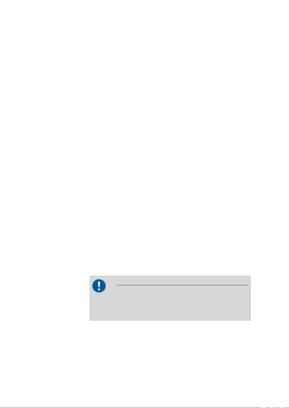
The Titrando is the heart of the modular Titrando system. Operation is carried out either by Touch Control with a touch-sensitive screen ("standalone titrator") or by a computer with a corresponding software.
A Titrando system can contain numerous kinds of a variety of instruments.
The following figure provides an overview of the peripheral devices you
can connect to the 901 Titrando.
1 Introduction
901 Titrando
Figure 1
The Titrando system
■■■■■■■■
1
Page 10

1.2 Instrument description
Up to three control instruments (Titrando, Dosing Interface, USB Sample
Processor, etc.) can be controlled via USB connection during operation
with the 900 Touch Control.
You can request information on special applications in the "Application
Bulletins" and "Application Notes", available free of charge through the
responsible Metrohm representative. Various monographs on the subjects
of titration techniques and electrodes are also available.
Updating the device software is described in the Help for the corresponding PC software.
1.2 Instrument description
The 901 Titrando has the following characteristics:
■ Operation
Operation is carried out by means of a touch-sensitive Touch Control
or with high-performance PC software.
■ MSB connectors
Four MSB connectors (Metrohm Serial Bus) for connecting dosing devi-
ces (Dosimat with exchange unit or Dosino with dosing unit), stirrers,
titration stands and Remote Boxes.
■ USB connectors
Two USB connectors, through which devices such as printers, PC key-
boards, barcode readers or additional control instruments (USB Sample
Processor, Titrando, Dosing Interface, etc.) can be connected.
■ Measuring interface
One measuring input each for:
– a potentiometric electrode (pH, metal or ion-selective electrode)
– a separate reference electrode
– a temperature sensor (Pt1000 or NTC)
– a polarizable electrode
– an iConnect (measuring interface for electrodes with integrated
data chip, so-called iTrodes)
■■■■■■■■■■■■■■■■■■■■■■
■■■■■■■■
2
901 Titrando
Page 11

■■■■■■■■■■■■■■■■■■■■■■
1 Introduction
1.3 Titration modes – Measuring modes – Dosing commands
The 901 Titrando supports the following titration modes, measuring
modes and dosing commands:
■ SET
Endpoint titration at one or two specified endpoints.
Measuring modes:
– pH (pH measurement)
– U (potentiometric voltage measurement)
– Ipol (voltametric measurement with selectable polarization cur-
rent)
– Upol (amperometric measurement with selectable polarization
voltage)
■ KFT
Volumetric water content determination according to Karl Fischer.
Measuring modes:
– Ipol (voltametric measurement with selectable polarization cur-
rent)
– Upol (amperometric measurement with selectable polarization
voltage)
■ MEAS
The following measuring modes can be selected for measurements:
– pH (pH measurement)
– U (potentiometric voltage measurement)
– Ipol (voltametric measurement with selectable polarization cur-
rent)
– Upol (amperometric measurement with selectable polarization
voltage)
– T (temperature measurement)
■ CAL
Electrode calibration.
Measuring mode:
– pH (calibration of pH electrodes)
■ ELT
Electrode test for pH electrodes.
This mode is listed separately only in tiamo™. In Touch Control, the
electrode test is a component part of the CAL calibration mode.
901 Titrando
■■■■■■■■
3
Page 12
1.4 About the documentation
■ Dosing commands
The following commands for dosing can be selected:
– PREP (rinsing the cylinder and tubings of an exchange unit or
dosing unit)
– EMPTY (emptying the cylinder and tubings of a dosing unit)
– ADD (dosing a specified volume)
– LQH (carrying out complex dosing tasks with a Dosino)
1.4 About the documentation
CAUTION
Please read through this documentation carefully before putting the
instrument into operation. The documentation contains information
and warnings which the user must follow in order to ensure safe operation of the instrument.
■■■■■■■■■■■■■■■■■■■■■■
1.4.1 Symbols and conventions
The following symbols and formatting may appear in this documentation:
Method Dialog text, parameter in the software
File ▶ New Menu or menu item
[Next] Button or key
Cross-reference to figure legend
The first number refers to the figure number, the second to the instrument part in the figure.
Instruction step
Carry out these steps in the sequence shown.
WARNING
This symbol draws attention to a possible life-threatening hazard or risk of injury.
WARNING
This symbol draws attention to a possible hazard due
to electrical current.
■■■■■■■■
4
WARNING
This symbol draws attention to a possible hazard due
to heat or hot instrument parts.
901 Titrando
Page 13
■■■■■■■■■■■■■■■■■■■■■■
1.5 Safety instructions
1.5.1 General notes on safety
WARNING
1 Introduction
WARNING
This symbol draws attention to a possible biological
hazard.
CAUTION
This symbol draws attention to possible damage to
instruments or instrument parts.
NOTE
This symbol highlights additional information and
tips.
This instrument may only be operated in accordance with the specifications in this documentation.
This instrument has left the factory in a flawless state in terms of technical
safety. To maintain this state and ensure non-hazardous operation of the
instrument, the following instructions must be observed carefully.
1.5.2 Electrical safety
The electrical safety when working with the instrument is ensured as part
of the international standard IEC 61010.
Only personnel qualified by Metrohm are authorized to carry out service
work on electronic components.
Never open the housing of the instrument. The instrument could be
damaged by this. There is also a risk of serious injury if live components
are touched.
WARNING
WARNING
901 Titrando
There are no parts inside the housing which can be serviced or replaced
by the user.
■■■■■■■■
5
Page 14
1.5 Safety instructions
■■■■■■■■■■■■■■■■■■■■■■
Mains voltage
WARNING
An incorrect mains voltage can damage the instrument.
Only operate this instrument with a mains voltage specified for it (see
rear panel of the instrument).
Protection against electrostatic charges
WARNING
Electronic components are sensitive to electrostatic charges and can be
destroyed by discharges.
Do not fail to pull the mains cable out of the mains connection socket
before you set up or disconnect electrical plug connections at the rear
of the instrument.
1.5.3 Working with liquids
CAUTION
Periodically check all system connections for leaks. Observe the relevant
regulations in respect to working with flammable and/or toxic fluids
and their disposal.
1.5.4 Flammable solvents and chemicals
WARNING
All relevant safety measures are to be observed when working with
flammable solvents and chemicals.
■ Set up the instrument in a well-ventilated location (e.g. fume cup-
board).
■ Keep all sources of flame far from the workplace.
■ Clean up spilled liquids and solids immediately.
■ Follow the safety instructions of the chemical manufacturer.
■■■■■■■■
6
901 Titrando
Page 15
■■■■■■■■■■■■■■■■■■■■■■
1.5.5 Recycling and disposal
This product is covered by European Directive 2002/96/EC, WEEE – Waste
from Electrical and Electronic Equipment.
The correct disposal of your old equipment will help to prevent negative
effects on the environment and public health.
More details about the disposal of your old equipment can be obtained
from your local authorities, from waste disposal companies or from your
local dealer.
1 Introduction
901 Titrando
■■■■■■■■
7
Page 16
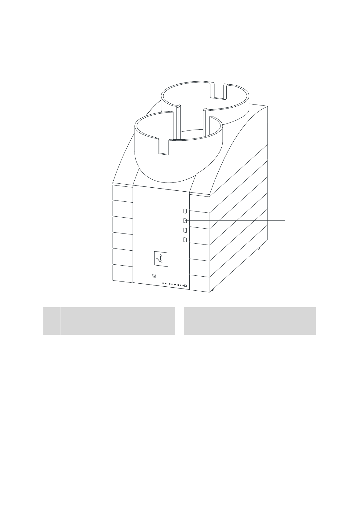
2 Overview of the instrument
On
901 Titrando
iTrode ready
1
2
Metrohm
■■■■■■■■■■■■■■■■■■■■■■
1
■■■■■■■■
8
Figure 2 Front 901 Titrando
Bottle holder
With holding clamps, for two reagent bottles.
"On" LED
2
Lights up when the Titrando is ready for
operation.
901 Titrando
Page 17
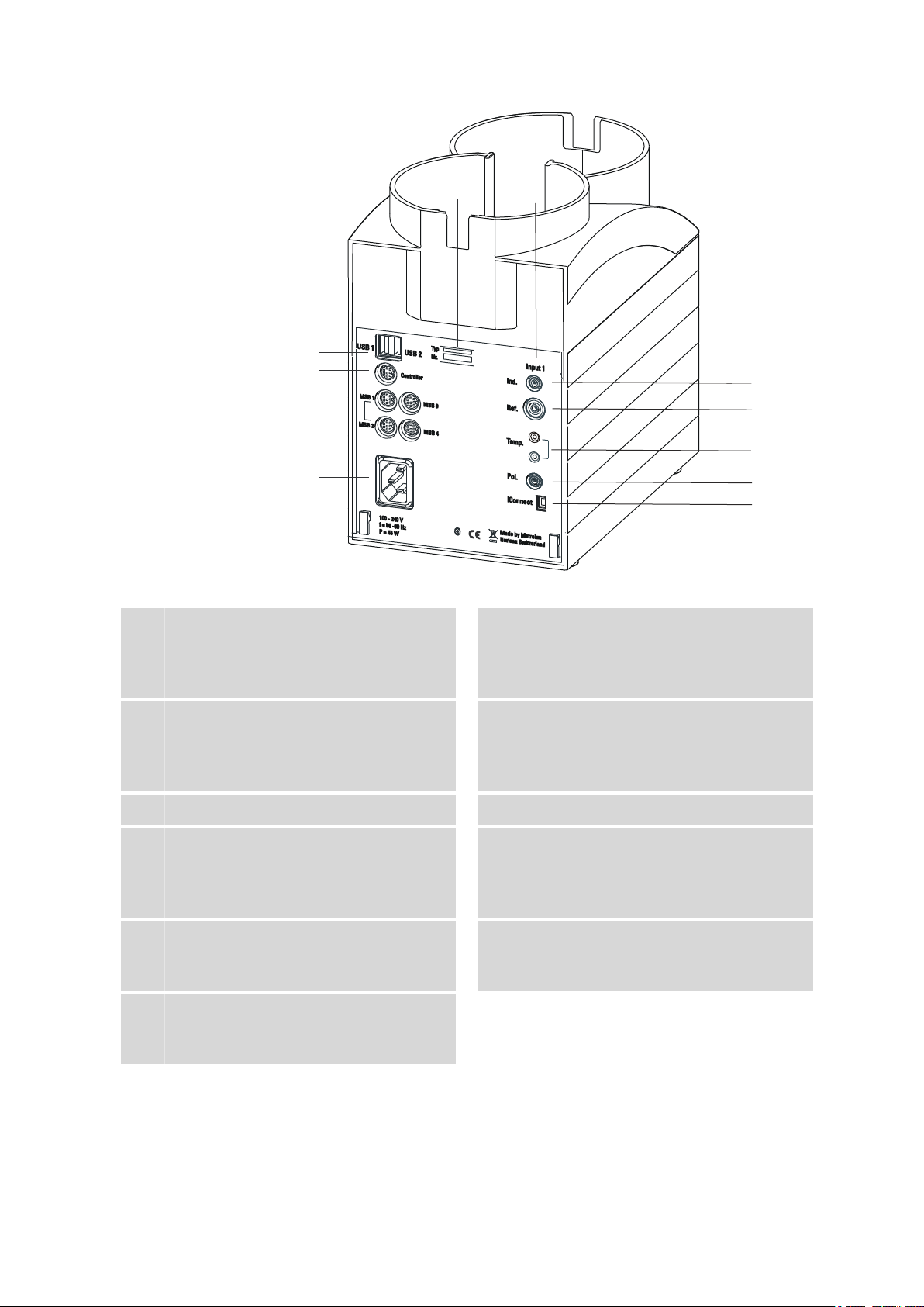
■■■■■■■■■■■■■■■■■■■■■■
1
2
3
4
5
6
7
8
9
10
11
2 Overview of the instrument
Figure 3 Rear 901 Titrando
Type plate
1
Contains specifications concerning supply
voltage, instrument type and serial number.
Connector (Controller)
3
For connecting a Touch Control or a PC with
installed PC software. Mini DIN, 9-pin.
Power socket
5
Electrode connector (Ind.)
7
For connecting pH, metal or ion-selective
electrodes with integrated or separated reference electrode. Socket F.
Temperature sensor connector (Temp.)
9
For connecting temperature sensors (Pt1000
or NTC). Two B sockets, 2 mm.
Electrode connector (iConnect)
11
For connecting electrodes with integrated
data chip (iTrodes).
USB connector (USB 1 and USB 2)
2
USB ports (type A) for connecting printer,
keyboard, barcode reader, additional Titrandos, USB Sample Processor, etc.
MSB connector (MSB 1 to MSB 4)
4
Metrohm Serial Bus. For connecting external
dosing devices, stirrers or Remote Boxes.
Mini DIN, 9-pin.
Measuring interface 1 (Input 1)
6
Electrode connector (Ref.)
8
For connecting reference electrodes, e.g.
Ag/AgCl reference electrode. Socket B,
4 mm.
Electrode connector (Pol.)
10
For connecting polarizable electrodes, e.g.
double Pt wire electrodes. Socket F.
901 Titrando
■■■■■■■■
9
Page 18
3.1 Setting up the instrument
3 Installation
3.1 Setting up the instrument
3.1.1 Packaging
The instrument is supplied in highly protective special packaging together
with the separately packed accessories. Keep this packaging, as only this
ensures safe transportation of the instrument.
3.1.2 Checks
Immediately after receipt, check whether the shipment has arrived complete and without damage by comparing it with the delivery note.
3.1.3 Location
The instrument has been developed for operation indoors and may not be
used in explosive environments.
■■■■■■■■■■■■■■■■■■■■■■
Place the instrument in a location of the laboratory which is suitable for
operation, free of vibrations, protected from corrosive atmosphere, and
contamination by chemicals.
The instrument should be protected against excessive temperature fluctuations and direct sunlight.
3.2 Connecting a controller
3.2.1 Operation
Two different versions are available for operating the 901 Titrando:
■ A Touch Control with touch-sensitive screen. It forms a "stand-alone
instrument" together with the 901 Titrando.
■ A computer enables operation of the 901 Titrando with the help of a
PC software, e.g. tiamo.
CAUTION
Take care to ensure that the power supply cable is pulled out of the
power socket before either setting up or disconnecting connections
between the instruments.
■■■■■■■■
10
901 Titrando
Page 19
■■■■■■■■■■■■■■■■■■■■■■
3.2.1.1 Connecting a Touch Control
NOTE
The plug is protected against accidental disconnection of the cable by
means of a pull-out protection feature. If you wish to pull out the plug,
you will first need to pull back the outer plug sleeve marked with
arrows.
Connect the Touch Control as follows:
■ Insert the plug of the Touch Control connection cable into the
1
Controller socket.
3 Installation
Figure 4 Connecting the Touch Control
■ Connect the MSB devices (see Chapter 3.3, page 14).
2
■ Connect the USB devices (see Chapter 3.4, page 18).
■ Connect the Titrando to the power supply.
3
■ Switch on the Touch Control.
4
The Touch Control power supply is supplied through the Titrando.
Automatic system tests are performed on both instruments at the
time of activation. The On LED on the front of the Titrando lights up
when the system test has been completed and the instrument is
ready for operation.
901 Titrando
■■■■■■■■
11
Page 20

3.2 Connecting a controller
■■■■■■■■■■■■■■■■■■■■■■
CAUTION
The Touch Control must be shut down properly by deactivation with
the power switch on the rear of the instrument before the power supply is interrupted. If this is not done, then there is a danger of data loss.
Because of the fact that the power supply for the Touch Control is provided through the Titrando, you must never disconnect the Titrando
from the power supply (e.g. by deactivating with a connector strip)
before you have deactivated the Touch Control.
If you would prefer not to position the Touch Control directly next to the
Titrando, then you can lengthen the connection with the 6.2151.010
cable. The maximum connection length permitted is 5 m.
3.2.1.2
Connecting a computer
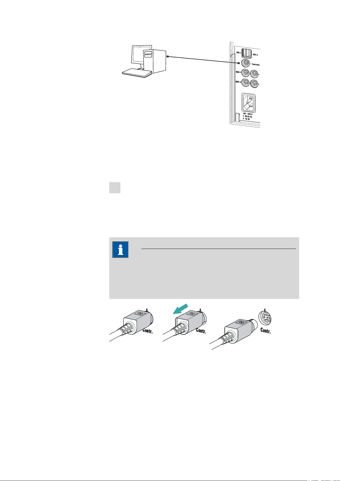
The 901 Titrando requires a USB connection to a computer in order to be
able to be controlled by a PC software. Using a 6.2151.000 controller
cable, the instrument can be connected directly, either to a USB socket on
a computer, to a connected USB hub or to a different Metrohm control
device.
You need administrator rights for the installation of driver software and
control software on your computer.
Cable connection and driver installation
A driver installation is required in order to ensure that the 901 Titrando is
recognized by the PC software. To accomplish this, you must comply with
the procedures specified. The following steps are necessary:
1
Installing the software
■ Insert the PC software installation CD and carry out the installa-
tion program directions.
■ Exit the program if you have started it after the installation.
2
Establishing the cable connections
■ Connect all peripheral devices to the instrument, see Chapter 3.3,
page 14 and see Chapter 3.4, page 18.
■ Connect the instrument to the power supply if you have not
already done this.
The "On" LED on the 901 Titrando is not yet illuminated!
■ Connect the instrument to a USB connector (Type A) of your com-
puter (see manual of your computer). The 6.2151.000 cable is
used for this purpose.
■■■■■■■■
12
901 Titrando
Page 21
■■■■■■■■■■■■■■■■■■■■■■
6.2151.000
Figure 5 Connecting the computer
The instrument is recognized. Depending on the version of the Windows operating system used, the driver installation proceeds differently afterwards. Either the necessary driver software is installed
automatically or an installation wizard is started.
Follow the instructions of the installation wizard.
3
3 Installation
The "On" LED on the 901 Titrando lights up when the driver installation has been completed and the instrument is ready for operation.
If problems should occur during installation, contact your company's IT
support team.
NOTE
The plug on the instrument end of the 6.2151.000 controller cable is
protected against accidental disconnection by means of a pull-out protection feature. If you wish to pull out the plug, you will first need to
pull back the outer plug sleeve marked with arrows.
Registering and configuring the instrument in the PC software
The instrument must be registered in the configuration of your PC software. Once that has been done, you can then configure it according to
your requirements. Proceed as follows:
901 Titrando
■■■■■■■■
13
Page 22

3.3 Connecting MSB devices
MSB
Stirrer / Ti Stand
Dosimat / Dosino
Dosimat
Remote Box
Dosino / Dosimat
Dosino
Relay Box
Ti Stand / Stirrer
1
Setting up the instrument
■ Start the PC software.
The instrument is automatically recognized. The configuration dialog for the instrument is displayed.
■ Make configuration settings for the instrument and its connec-
tors.
More detailed information concerning the configuration of the
instrument can be found in the documentation for the respective PC
software.
3.3 Connecting MSB devices
In order to connect MSB devices, e.g. stirrers or dosing devices, Metrohm
instruments are equipped with up to a maximum of four connectors on
what is referred to as the Metrohm Serial Bus (MSB). Various kinds of
peripheral devices can be connected in sequence (in series, as a
"daisy chain") at a single MSB connector (8-pin Mini DIN socket) and controlled simultaneously by the respective control instrument. In addition to
the connection cable, stirrers and the Remote Box are each equipped with
their own MSB socket for this purpose.
■■■■■■■■■■■■■■■■■■■■■■
The following figure provides an overview of the instruments that can be
connected to an MSB socket, along with a number of different cabling
variations.
Figure 6
MSB connections
The control instrument determines which peripheral devices are supported.
■■■■■■■■
14
901 Titrando
Page 23

■■■■■■■■■■■■■■■■■■■■■■
3 Installation
NOTE
When connecting MSB devices together, the following must be
observed:
■ Only one device of the same type can be used at a single MSB con-
nector at one time.
■ Type 700 Dosino and 685 Dosimat dosing devices cannot be con-
nected together with other MSB instruments on a shared connector.
These dosing devices must be connected separately.
CAUTION
Exit the control software before you plug in MSB instruments. When it
is switched on, the control instrument automatically recognizes which
device is connected to which MSB connector. The operating unit or the
control software enters the connected MSB devices into the system
configuration (device manager).
MSB connections can be extended with the 6.2151.010 cable. The maximum connection length permitted is 15 m.
3.3.1 Connecting a dosing device
Four dosing devices can be connected to the instrument (MSB 1 to MSB
4).
The types of dosing devices that are supported are:
■ 800 Dosino
■ 700 Dosino
■ 805 Dosimat
■ 685 Dosimat
Proceed as follows:
1
Connecting a dosing device
■ Exit the control software.
■ Connect the connection cable of the dosing device to one of the
sockets marked with MSB on the rear of the control instrument.
■ Start the control software.
901 Titrando
■■■■■■■■
15
Page 24

3.3 Connecting MSB devices
Figure 7 Connecting a dosing device
3.3.2 Connecting a stirrer or titration stand
You can use the following instruments:
■■■■■■■■■■■■■■■■■■■■■■
■ With built-in magnetic stirrer (stirring "from below"):
– 801 Stirrer
– 803 Ti Stand
■ Without built-in magnetic stirrer (stirring "from above"):
– 804 Ti Stand with propeller stirrer 802 Stirrer
Connect a stirrer or a titration stand as follows:
1
Connecting the stirrer or titration stand
■ Exit the control software.
■ Connect the connection cable of the magnetic stirrer or of the
titration stand to one of the sockets marked with MSB on the
rear of the control instrument.
■ 804 Ti Stand only: Connect the propeller stirrer to the stirrer con-
nector (socket with stirrer symbol) of the titration stand.
■ Start the control software.
■■■■■■■■
16
901 Titrando
Page 25

■■■■■■■■■■■■■■■■■■■■■■
3 Installation
Figure 8 Connecting an MSB stirrer
Figure 9 Connecting the propeller stirrer to the titration stand
3.3.3 Connecting a Remote Box
Instruments that are controlled via remote lines and/or that send control
signals via remote lines can be connected via the 6.2148.010 Remote Box.
In addition to Metrohm, other instrument manufacturers also use similar
connectors that make it possible to connect different instruments
together. These interfaces are also frequently given the designations "TTL
Logic", "I/O Control" or "Relay Control" and generally have a signal level
of 5 volts.
Control signals are understood to be electrical line statuses or electrical
pulses (> 200 ms) which display the operating status of an instrument or
which trigger or report an event. Sequences on a variety of instruments
can thus be coordinated in a single complex automation system. No
exchange of data is possible, however.
Proceed as follows:
1
Connecting the Remote Box
■ Exit the control software.
901 Titrando
■■■■■■■■
17
Page 26

3.4 Connecting USB devices
■■■■■■■■■■■■■■■■■■■■■■
■ Connect the Remote Box connection cable to one of the sockets
marked with MSB on the rear of the control instrument.
■ Start the control software.
Figure 10 Connecting the Remote Box
You can, for example, connect an 849 Level Control (fill level monitoring
in a canister) or a 731 Relay Box (switch box for 230/110 volt alternating
current sockets and low-voltage direct current outlets). The Remote Box
also has an MSB socket at which a further MSB device, e.g. a dosing
device or a stirrer, can be connected.
You will find precise information concerning the pin assignment of the
interface on the Remote Box in the appendix.
3.4 Connecting USB devices
3.4.1 General
The 901 Titrando has two USB connectors (type A sockets) for peripheral
devices with USB interfaces. The Titrando functions as a USB hub (distributor) no matter how it is operated. If you wish to connect more than two
devices to the USB, you can also use an additional, commercially available
USB hub.
CAUTION
If you operate the 901 Titrando with the aid of the Touch Control, take
care to ensure that the Touch Control is switched off when you set up
or disconnect connections between the various instruments. If you use
a PC software to control the 901 Titrando, you should exit the program
before you set up or disconnect the USB connections.
■■■■■■■■
18
901 Titrando
Page 27

■■■■■■■■■■■■■■■■■■■■■■
3.4.2 Connecting a USB hub
If you wish to connect more than two devices to the USB connector of the
901 Titrando, you can also use an additional commercially available USB
hub (distributor). If you operate the 901 Titrando with the help of the
Touch Control, then you should use a USB hub with its own power supply.
Connect the USB hub as follows:
Switch off the Touch Control and/or exit the PC software.
1
With the aid of the 6.2151.020 cable, connect the USB connector of
2
the 901 Titrando (type A) with the USB connector of the hub (type B,
see manual for the hub).
Switch on the Touch Control.
3
The USB hub is recognized automatically.
3 Installation
3.4.3 Connecting a printer
Printers that are connected to the 901 Titrando with Touch Control must
meet the following requirements:
■ Printer languages: HP-PCL (PCL 3 to 5, PCL 3GUI), Canon BJL Com-
mands or Epson ESC P/2
■ Printer resolution: 300 dots/inch or 360 dots/inch (Epson)
■ Paper size: A4 or Letter, single-sheet feed.
Connect the printer as follows:
Switch off the Touch Control.
1
With the aid of the 6.2151.020 cable, connect the USB connector of
2
the 901 Titrando (type A) with the USB connector of the printer (type
B, see manual for the printer).
Switch on the printer first, then the Touch Control.
3
Configure the printer in the device manager of the Touch Control
4
(see Touch Control manual).
901 Titrando
■■■■■■■■
19
Page 28

3.4 Connecting USB devices
Figure 11 Connecting a printer
3.4.4 Connecting a balance
■ Operation with a PC software:
– Connect the balance directly to the serial connector (COM) of
the computer. This is usually 9-pin and marked with the symbol
IOIOI.
■ Operation with Touch Control:
– You will need the 6.2148.050 USB/RS-232 adapter to connect a
balance.
■■■■■■■■■■■■■■■■■■■■■■
The following table offers an overview of the balances that you can use
together with the 901 Titrando and of which cable you will need for connection to the RS-232 interface:
Balance
AND ER, FR, FX with RS-232 inter-
Cable
6.2125.020 + 6.2125.010
face (OP-03)
Mettler AB, AG, PR (LC-RS9) In the scope of delivery for the
balance
Mettler AM, PM, PE with interface
option 016
or
Mettler AJ, PJ with interface
option 018
6.2146.020 + 6.2125.010
Also from Mettler: ME 47473
adapter and either ME 42500
hand switch or ME 46278 foot
switch
Mettler AT 6.2146.020 + 6.2125.010
Also from Mettler: ME 42500
hand switch or ME 46278 foot
switch
■■■■■■■■
20
Mettler AX, MX, UMX, PG, AB-S,
PB-S, XP, XS
6.2134.120
901 Titrando
Page 29
■■■■■■■■■■■■■■■■■■■■■■
3 Installation
Balance Cable
Mettler AE with interface option
011 or 012
6.2125.020 + 6.2125.010
Also from Mettler: ME 42500
hand switch or ME 46278 foot
switch
Ohaus Voyager, Explorer, Analyti-
Cable AS017-09 from Ohaus
cal Plus
Precisa balances with RS-232-C
6.2125.080 + 6.2125.010
interface
Sartorius MP8, MC, LA, Genius,
6.2134.060
Cubis
Shimadzu BX, BW 6.2125.080 + 6.2125.010
Operation with Touch Control
Connect the balance as follows:
Plug in the USB plug of the USB/RS-232 adapter at the USB connec-
1
tor of the 901 Titrando.
Connect the RS-232 interface of the USB/RS-232 adapter with the
2
RS-232 interface of the balance (see table for cable).
Switch on the Touch Control.
3
Switch on the balance.
4
Activate the RS-232 interface of the balance if necessary.
5
Configure the RS-232 interface of the USB/RS-232 adapter in the
6
device manager of the Touch Control (see Touch Control manual).
3.4.5 Connecting a PC keyboard (only for operation with Touch Control)
The PC keyboard is used as an aid for text and numerical input.
Connect the PC keyboard as follows:
Insert the USB plug of the keyboard into one of the USB sockets of
1
the 901 Titrando.
901 Titrando
■■■■■■■■
21
Page 30

3.4 Connecting USB devices
Switch on the Touch Control.
2
The keyboard is recognized automatically and entered in the device
manager.
Configure the keyboard in the device manager of the Touch Control
3
(see Touch Control manual).
3.4.6 Connecting a barcode reader
The barcode reader is used as an aid for text and numerical input. You can
connect a barcode reader with USB interface.
Operation with Touch Control
Connect the barcode reader as follows:
Insert the USB plug of the barcode reader into one of the USB sock-
1
ets of the 901 Titrando.
Switch on the Touch Control.
2
■■■■■■■■■■■■■■■■■■■■■■
The barcode reader is recognized automatically and entered in the
device manager.
Configure the barcode reader in the device manager of the Touch
3
Control (see Touch Control manual).
Settings on the barcode reader:
Program the barcode reader as follows (see also the manual for the barcode reader):
Switch the barcode reader to programming mode.
1
Specify the desired layout for the keyboard (USA, Germany, France,
2
Spain, German-speaking Switzerland).
This setting must match the setting in the device manager (see the
Touch Control manual).
Make sure that the barcode reader is set in such a way that Ctrl char-
3
acters (ASCII 00 to 31) can be sent.
■■■■■■■■
22
901 Titrando
Page 31

■■■■■■■■■■■■■■■■■■■■■■
1
2
3
1
2
3
a)
b)
Program the barcode reader in such a way that the ASCII character
4
02 (STX or Ctrl B) is sent as the first character. This first character is
normally referred to as the "Preamble" or "Prefix Code".
Program the barcode reader in such a way that the ASCII character
5
04 (EOT or Ctrl D) is sent as the last character. This last character is
normally referred to as the "Postamble", "Record Suffix" or "Postfix
Code".
Exit the programming mode.
6
3.5 Setting up the titration vessel
3.5.1 General
During the titration, it is important that the solution be well-mixed. The
stirring rate should be high enough for a small "vortex" to appear. If the
stirring rate is too high, then air bubbles will be aspirated. This results in
incorrect measured values. If the stirring rate is too low, then the solution
at the electrode will not be correctly mixed. In order to ensure that measurement is carried out in a well-mixed solution following addition of the
titrant, the buret tip should be placed in a position where the turbulence is
high. In addition, the distance between the addition of the titrant and the
electrode should be as large as possible. Also take into account the stirring
direction (counterclockwise or clockwise) when positioning electrode and
buret tip (see figure below).
3 Installation
Figure 12
Schematic configuration of magnetic stirrer, electrode and
buret tip during a titration. a) stirring direction clockwise, b)
stirring direction counterclockwise.
Magnetic stirrer
1
Buret tip
3
901 Titrando
2
Electrode
■■■■■■■■
23
Page 32

3.5 Setting up the titration vessel
1
2
4
3
6.1414.030
6.2013.010
6.1415.220
6.1903.020
3.5.2 Titration vessel for volumetric KF titration
Mounting the KF titration cell
■■■■■■■■■■■■■■■■■■■■■■
Proceed as follows:
Screw the 6.2013.010 clamping ring tightly to the support rod.
1
Fix the 6.1414.030 vessel lid of the KF titration cell (with correctly
2
inserted sealing ring from the 6.1244.040 sealing set) to the support
rod. Keep the locking lever pressed down until it can be released at
the desired position.
Fasten the 6.1415.220 (or 6.1415.250) titration vessel with a
3
6.1903.020 (or 6.1903.030) stirring bar inside on the vessel lid. Fold
back the holding bracket upwards while doing so. The markings on
the vessel lid and on the plastic ring must be aligned above one
another. Afterwards, press the holding bracket downwards in order
to fix the titration vessel. The levers of the holding bracket must
enclose the pins of the plastic ring on the titration vessel in order to
ensure a secure hold.
■■■■■■■■
24
901 Titrando
Page 33

■■■■■■■■■■■■■■■■■■■■■■
3
6.1403.040
1
2
3
6.2811.000
3 Installation
Adjust the height of the KF titration cell by pressing the locking lever.
4
It should almost touch the surface of the stirrer. The position can
now be fixed by readjusting the clamping ring.
Once the height of the KF titration cell has been adjusted correctly,
the entire cell can be raised and swiveled as required by pressing the
locking lever.
Filling the adsorber tube
Before insertion, the 6.1403.040 adsorber tube must be filled with the
6.2811.000 molecular sieve. Proceed as follows:
901 Titrando
Insert a small cotton plug into the bottom of the adsorber tube. Do
1
not pack the cotton too tightly.
Fill the molecular sieve up to the ¾ level.
2
Place a small cotton plug on the molecular sieve. Do not pack the
3
cotton too tightly.
Seal the adsorber tube with the appropriate cover.
4
■■■■■■■■
25
Page 34

3.5 Setting up the titration vessel
1
6
2
5
3
6.2730.030
6.1543.110
6.1543.120
1
1
6.1805.200
6.1543.060
4
■■■■■■■■■■■■■■■■■■■■■■
Inserting the dosing tip, aspiration tip and buret tip
Proceed as follows:
Place the three screw nipples from 6.2730.030 (including O-rings,
1
but without stoppers) in the rear openings of the vessel lid.
Insert the 6.1543.110 dosing tip through the screw nipple in the
2
middle rear opening.
Insert the 6.1543.120 aspiration tip through the screw nipple in the
3
right rear opening.
When solvent is aspirated, the end of the aspiration tip must touch
the vessel base, but it must not inhibit the action of the stirring bar.
The aspiration tip can, if needed, be pulled out of the solvent.
Insert the 6.1543.060 buret tip through the screw nipple in the left
4
rear opening.
Screw the 6.1805.200 PTFE M8 tubing of the aspiration bottle onto
5
the aspiration tip.
■■■■■■■■
26
901 Titrando
Page 35
■■■■■■■■■■■■■■■■■■■■■■
6.2730.020
6.2730.010
6.0338.100
6.1403.040
6.2104.020
1
2
3
4
5
6
3 Installation
Screw the 6.1805.200 PTFE M8 tubing of the solvent bottle onto the
6
dosing tip.
Inserting electrode, adsorber tube and septum stoppers
Proceed as follows:
Introduce the 6.2730.020 septum stopper (with septum inserted)
1
into the front opening of the vessel lid.
Insert the O-rings of the electrode and of the adsorber tube into the
2
middle openings of the vessel lid.
Screw the two 6.2730.010 screw nipples into the openings with the
3
O-rings. Do not screw too tightly.
Introduce the 6.0338.100 double Pt electrode into the left-hand
4
opening and then tighten the screw nipple until it seals.
Screw the 6.2104.020 electrode cable tightly onto the electrode.
5
901 Titrando
■■■■■■■■
27
Page 36

3.6 Connecting sensors
Insert the filled 6.1403.040 adsorber tube on the right of the elec-
6
■■■■■■■■■■■■■■■■■■■■■■
trode into the remaining opening and then tighten the screw nipple
until it seals.
3.6 Connecting sensors
The measuring interface contains the following measuring inputs:
■ Ind. for a potentiometric electrode (pH, metal or ion-selective elec-
trode)
■ Ref. for a separate reference electrode
■ Temp. for a temperature sensor (Pt1000 or NTC)
■ Pol. for a polarizable electrode
■ iConnect for an iConnect (measuring interface for electrodes with
integrated data chip, so-called iTrodes)
3.6.1 Connecting a pH, metal or ion-selective electrode
Connect the pH, metal or ion-selective electrode as follows:
Plug the electrode plug into the Ind. socket of the 901 Titrando.
1
■■■■■■■■
28
Figure 13 Connecting a pH, metal or ion-selective electrode
NOTE
The electrode cable is protected against accidental disconnection
of the cable by means of a pull-out protection. If you wish to pull
out the plug again, you will first need to pull back the outer plug
sleeve.
901 Titrando
Page 37
■■■■■■■■■■■■■■■■■■■■■■
3.6.2 Connecting a reference electrode
Connect the reference electrode as follows:
Plug the electrode plug into the Ref. socket of the 901 Titrando.
1
Figure 14 Connecting a reference electrode
3.6.3 Connecting a polarizable electrode
Connect the polarizable electrode as follows:
Plug the electrode plug into the Pol. socket of the 901 Titrando.
1
3 Installation
901 Titrando
Figure 15 Connecting a polarizable electrode
NOTE
The electrode cable is protected against accidental disconnection
of the cable by means of a pull-out protection. If you wish to pull
out the plug again, you will first need to pull back the outer plug
sleeve.
■■■■■■■■
29
Page 38

3.6 Connecting sensors
■■■■■■■■■■■■■■■■■■■■■■
3.6.4 Connecting a temperature sensor or an electrode with integrated temperature sensor
A temperature sensor of the Pt1000 or NTC type can be connected to the
Temp. connector.
Connect the temperature sensor or the electrode with integrated temperature sensor as follows:
Insert the plugs of the temperature sensor into the Temp. sockets of
1
the Titrando.
Figure 16 Connecting a temperature sensor or an electrode with
integrated temperature sensor
Always insert the red plug into the red socket. This is the only way
that shielding against electrical interference can be ensured.
3.6.5 Connecting an iConnect
An external 854 iConnect measuring interface can be connected to the
901 Titrando.
Connect the iConnect as follows:
Plug the iConnect plug into the iConnect socket of the 901
1
Titrando.
Take care to ensure that the marking on the plug matches the marking on the Titrando as shown in the figure.
NOTE
■■■■■■■■
30
901 Titrando
Page 39

■■■■■■■■■■■■■■■■■■■■■■
3 Installation
Figure 17 Connecting the iConnect
The iConnect is detected automatically and entered as measuring
input into the device properties of the Titrando. If an electrode is
connected to the iConnect that is not yet included in the list of sensors for the control software, then a corresponding message will be
displayed.
The iConnect can be plugged in and unplugged while the Titrando is
switched on.
An electrode with integrated data chip, referred to as iTrode, is connected
to the iConnect.
Connect the electrode as follows:
Remove the protective caps on the iConnect and the electrode.
1
Plug in the electrode on the iConnect as illustrated below.
2
Figure 18 Connecting an electrode to the iConnect
The guide pin guarantees correct connection in such a way that the
contact pins cannot be damaged.
Screw the iConnect tightly.
3
3.6.6 Differential potentiometry
Potentiometric measurements with high-ohm measuring chains can be
disrupted by electrostatic and electromagnetic fields in media with low
conductivity. Use our 6.0229.100 Solvotrode or other special electrodes
for pH measurements in organic solvents. If no reliable measurements are
possible with these, then a 6.5104.030 (230 V) or 6.5104.040 (115 V) dif-
901 Titrando
■■■■■■■■
31
Page 40

3.6 Connecting sensors
■■■■■■■■■■■■■■■■■■■■■■
ferential amplifier can be used. The differential amplifier is connected to
the high-ohm measuring input (Ind.).
■■■■■■■■
32
901 Titrando
Page 41

■■■■■■■■■■■■■■■■■■■■■■
4 Karl Fischer titration
4.1 Volumetric titration
4.1.1 Principle of the volumetric Karl Fischer titration
The volumetric Karl Fischer titration is the classic method of water
content determination. It works with a methanolic solution of iodine, sulfur dioxide and a base as buffer substance. If an aqueous sample is titrated, then several reactions take place that can be summarized in the following sum equation:
H2O + I2 + [RNH]SO3CH3 + 2 RN ⇄ [RNH]SO4CH3 + 2 [RNH]I
According to the equation above, I2 reacts quantitatively with H2O. This
chemical equation serves as a basis for the water content determination.
4 Karl Fischer titration
The classic Karl Fischer method has undergone continuous further development in recent years. This development did not concern itself solely
with the refining and automation of reagent dosing, but also with improving endpoint indication and reagents. The disadvantage of this method is
that the reagents are not completely stable. This means that the titer has
to be re-determined on a regular basis.
4.1.2 Endpoint determination
The titration endpoint is determined by an electrometric indication
method. Double Pt wire electrodes or double Pt ring electrodes are used
for this purpose. A distinction is made between the following two indication methods:
Biamperometric indication (Upol)
A constant potential is applied to the electrodes and the resulting current
is measured.
Bivoltametric indication (Ipol)
A direct or alternating current is applied between the two electrodes and
the resulting potential is measured.
901 Titrando
■■■■■■■■
33
Page 42

4.1 Volumetric titration
4.1.3 Karl Fischer reagents
One-component reagents
They contain all the reactive parts in a single solution – iodine, sulfur dioxide and a base, dissolved in an appropriate alcohol.
Two-component reagents
The reactive parts are distributed among two separated solutions. The
titration reagent contains iodine in methanol. The KF solvent is a solution
of sulfur dioxide and a base in methanol. It is used as a working medium
in the KF titration cell.
4.1.4 Application of the Karl Fischer titration
The volumetric Karl Fischer titration is the method of choice for determining quantities of water between 0.1 and 100%. It has the advantage that
even solid and pasty samples can be added directly to the titration vessel.
In addition, various organic solvents can be used that are tailored to the
respective samples.
■■■■■■■■■■■■■■■■■■■■■■
4.1.5 Working with water standards
4.1.5.1
4.1.5.2
Certified water standards
Commercially available, certified water standards with a water content of
10.0 ± 0.1 mg/g should be used for validating the instrument as a whole,
integrated system.
Practical recommendations
For validation, it is essential to work very accurately. In order to minimize
any measurement inaccuracies that could occur, the sample preparation
and the sample processing should proceed in accordance with a defined
scheme:
Put on gloves (always with Karl Fischer titration).
1
Use a clean syringe.
2
Take a new ampoule of water standard and shake it briefly.
3
With a folded paper towel held between thumb and index finger,
4
break open the ampoule at the marking.
Draw approx. 1 mL of the water standard into the syringe.
5
■■■■■■■■
34
901 Titrando
Page 43

■■■■■■■■■■■■■■■■■■■■■■
4 Karl Fischer titration
Pull the piston of the syringe up to the end and swing the syringe
6
back and forth somewhat.
The inside of the syringe is being rinsed by water standard and freed
from water contamination.
Dispose of the used water standard in a waste bottle.
7
Draw the rest of the water standard into the syringe, aspirating as lit-
8
tle air as possible.
Push out any air bubbles that may be present in the syringe.
9
Wipe off the needle with a lint-free paper towel and cover it with the
10
appropriate cap.
Place the syringe on the balance and press [TARA].
11
As soon as the drift on the 901 Titrando is stable, take the syringe by
12
hand, press [START] and inject approx. 1 mL of the water standard
through the septum.
There are two possibilities:
■ Version 1:
Inject the water standard without immersing the needle in the
reagent liquid. If a little drop remains on the end of the needle, it
must be aspirated back before pulling the needle out of the septum.
The water standard should not be sprayed from the syringe onto
the electrode nor onto the wall of the titration vessel.
■ Version 2:
Inject the water standard directly under the surface of the reagent
liquid.
Take care to ensure that you do not aspirate any liquid when you
withdraw the syringe from the reagent liquid.
Close the syringe with the same cap and place it back on the bal-
13
ance.
Read off the value displayed by the balance and enter it as sample
14
size on the Touch Control or in the PC software (e.g. tiamo).
901 Titrando
■■■■■■■■
35
Page 44

4.1 Volumetric titration
The next determination can be started as soon as the determination
15
has been finished and the titration cell has been conditioned (drift
stable) again.
4.1.6 Sample addition
This chapter contains a few notes concerning sample addition. Further
notes can be found in the publications of the reagent manufacturers and
in the Karl Fischer monograph published by Metrohm.
4.1.6.1 Size of the sample size
The sample weight should be small in order to be able to titrate as many
samples as possible in the same electrolyte solution and in order to keep
the titration time short. However, ensure that the sample contains at least
50 µg of H2O. The following tables provide clues for the sample size.
■■■■■■■■■■■■■■■■■■■■■■
Table 1
Water content of
Approximate sample size in grams (5 mL buret)
KF reagent 1 KF reagent 2 KF reagent 5
the sample
0.5% 0.1 - 0.9 0.2 - 1.8 0.5 - 4.5
1.0% 0.05 - 0.45 0.1 - 0.9 0.25 - 2.25
5.0% 0.02 - 0.18 0.05 - 0.45
10.0% 0.03 - 0.22
25.0%
50.0%
Table 2 Approximate sample size in grams (10 mL buret)
Water content of
KF reagent 1 KF reagent 2 KF reagent 5
the sample
0.5% 0.2 - 1.8 0.4 - 3.6
1.0% 0.1 - 0.9 0.2 - 1.8 0.5 - 4.5
5.0% 0.02 - 0.18 0.04 - 0.36 0.1 - 0.9
10.0% 0.02 - 0.18 0.05 - 0.45
25.0% 0.02 - 0.18
50.0% 0.02 - 0.09
■■■■■■■■
36
901 Titrando
Page 45
■■■■■■■■■■■■■■■■■■■■■■
Table 3 Approximate sample size in grams (20 mL buret)
4 Karl Fischer titration
Water content of
KF reagent 1 KF reagent 2 KF reagent 5
the sample
0.5% 0.4 - 3.6
1.0% 0.2 - 1.8 0.4 - 3.6
5.0% 0.04 - 0.36 0.08 - 0.72 0.2 - 1.8
10.0% 0.02 - 0.18 0.04 - 0.36 0.1 - 0.9
25.0% 0.02 - 0.14 0.04 - 0.36
50.0% 0.02 - 0.18
KF reagent 1: 1 mL KF reagent reacts with around 1 mg H2O
KF reagent 2: 1 mL KF reagent reacts with around 2 mg H2O
KF reagent 5: 1 mL KF reagent reacts with around 5 mg H2O
4.1.6.2
Working with liquid samples
Liquid samples are added with a syringe. The samples can be injected
two different ways:
■ One uses a syringe with a long needle, which one immerses in the
reagent during the injection.
■ One uses a syringe with a short needle and aspirates the last drops
back into the needle.
The best way for you to determine the injected sample amount is to
reweigh the sample.
Glass syringes should be used for the determination of traces and val-
idations. We recommend obtaining these from a specialized syringe
manufacturer.
Highly volatile samples and samples of low viscosity should be
cooled before sampling. Doing so avoids losses while working. The syringe
must, however, not be cooled directly, as condensation could form. For
the same reason, no air may be aspirated into a syringe into which a
cooled sample has been aspirated beforehand.
Samples of high viscosity can be thinned by heating. The syringe must
be heated as well. The same target can be reached by diluting with suitable solvents. In this case, the water content of the solvent has to be
determined and subtracted as blank value.
Viscous samples can be added to the measuring cell with a syringe
without needle. You can use the ground-joint opening for this. The best
way for you to determine the added sample amount is by reweighing the
sample.
901 Titrando
■■■■■■■■
37
Page 46

4.1 Volumetric titration
4.1.6.3 Working with solid samples
If possible, solid samples are to be extracted or dissolved in a suitable solvent. The resulting solution is injected, during which a blank value correction for the solvent must be carried out.
If no suitable solvent can be found for a solid sample, or if the sample
reacts with the Karl Fischer reagent, then a Karl Fischer oven should be
used.
If solid samples have to be directly added to the titration cell, they can be
inserted through the ground-joint opening. While doing so, take care to
ensure that
■ the sample releases its moisture completely.
■ no side reaction with the Karl Fischer reagent takes place.
■ the surface of the electrode is not covered by the sample substance
(incomplete KF reaction!).
■ the Pt wires of the indicator electrode do not become damaged.
4.1.7 Optimum working conditions
■■■■■■■■■■■■■■■■■■■■■■
4.1.7.1
4.1.7.2
Drift
A constant drift in the range of ≤ 10 µL/min is all right. Lower values are,
however, quite possible. Higher but stable values will still produce good
results, because the drift can be compensated.
A constantly high drift can be caused by water-containing deposits in
inaccessible parts of the titration vessel. In these cases, shaking the titration vessel can reduce the value. Make sure that there are no drops above
the liquid level in the titration vessel.
When you work with a Karl Fischer oven, a drift ≤ of 10 µL/min is all right.
The drift depends on the gas flow (the smaller the gas flow, the lower the
drift).
Reagent replacement
The electrolyte solution must be replaced in the following cases:
■ The titration vessel is too full.
■ The drift is too high, and cannot be reduced by shaking the titration
vessel.
Exhausted electrolyte solution is best disposed of by aspiration. To do this,
you can use, for example, an 803 Ti Stand with built-in membrane pump.
An advantage is that the titration vessel does not have to be disassembled.
■■■■■■■■
38
In the event of severe contamination, the titration vessel can be rinsed
with a suitable solvent which is also aspirated.
901 Titrando
Page 47

■■■■■■■■■■■■■■■■■■■■■■
4.1.7.3 Indicator electrode
A new indicator electrode can take a certain warm-up time for forming
the surface. During this time unexpectedly long titration times and high
measurement results can occur. This phenomenon will, however, disappear after a short time of use. In order to accelerate the setting of a new
indicator electrode, the 901 Titrando can be conditioned e.g. over night.
A contaminated indicator electrode can be carefully cleaned with an abrasive agent (6.2802.000 polishing set or toothpaste). After the cleaning,
rinse with ethanol.
The two Pt wires of the indicator electrode should run as parallel as possible to one another. Check the Pt wires before inserting the electrode.
4 Karl Fischer titration
901 Titrando
■■■■■■■■
39
Page 48

5.1 General notes
5 Operation and maintenance
5.1 General notes
5.1.1 Care
The 901 Titrando requires appropriate care. Excess contamination of the
instrument may result in functional disruptions and a reduction in the service life of the otherwise sturdy mechanics and electronics.
Spilled chemicals and solvents should be removed immediately. Above all,
the plug connections on the rear of the instrument (in particular the
power socket) should be protected from contamination.
CAUTION
Although this is largely prevented by design measures, the power plug
should be unplugged immediately if aggressive media have found their
way into the interior of the instrument to prevent serious damage to
the instrument electronics. In such cases, Metrohm Service must be
informed.
■■■■■■■■■■■■■■■■■■■■■■
5.1.2 Maintenance by Metrohm Service
Maintenance of the 901 Titrando is best carried out as part of annual service, which is performed by specialist personnel from Metrohm. A shorter
maintenance interval may be necessary if you frequently work with caustic
and corrosive chemicals.
Metrohm Service offers every form of technical advice for maintenance
and service of all Metrohm instruments.
■■■■■■■■
40
901 Titrando
Page 49

■■■■■■■■■■■■■■■■■■■■■■
5 Operation and maintenance
5.2 Quality management and qualification with Metrohm
Quality management
Metrohm offers you comprehensive support in implementing quality management measures for instruments and software.
Qualification
Please contact your local Metrohm representative for support in qualification of instruments and software. The Installation Qualification (IQ)
and Operational Qualification (OQ) are offered by Metrohm representatives as a service. They are carried out by trained employees using standardized qualification documents and in accordance with the currently
applicable requirements of the regulated industry.
Maintenance
The electronic and mechanical functional groups of Metrohm instruments
can and should be checked by specialist personnel from Metrohm as part
of a regular preventive maintenance schedule. Please ask your local
Metrohm representative regarding the precise terms and conditions
involved in concluding a corresponding maintenance agreement.
For detailed information on this topic, please visit www.metrohm.com.
901 Titrando
■■■■■■■■
41
Page 50

6.1 General
6 Troubleshooting
6.1 General
Problem Cause Remedy
■■■■■■■■■■■■■■■■■■■■■■
The "On" LED is not
illuminated, even
though the instrument is connected
to the power supply.
The Touch Control or the
computer has not been
switched on yet or the
plugs are not correctly
plugged in.
6.2 Karl Fischer titration
Problem
The drift is very high
during conditioning.
The drift becomes
greater after each
titration.
Cause Remedy
The titration cell is leaking. ■ Check the seals and the septum. Replace if
The sample releases water
very slowly.
A side reaction is taking
place.
1. Check the plug connections.
2. Switch on the Touch Control or the computer.
necessary.
■ Replace the molecular sieve.
■ Adjust the method.
■ Add solubility promoter.
■ Increase the temperature (possibly using a
KF oven).
■ See technical literature.
■ Use special reagents.
■ Adjust the method (increase/decrease the
temperature, external extraction).
■ See technical literature.
The titration will not
be finished.
■■■■■■■■
42
The pH value is no longer
Add buffer (see technical literature).
in the optimum range.
The titration cell is leaking. ■ Check the seals and the septum. Replace if
necessary.
■ Replace the molecular sieve.
The minimum increment is
too low.
Select the user-defined titration rate and
increase the minimum volume increment (see
manual/help of the software used).
The stop criterion is unsuitable.
Adjust the control parameters (see manual/
help of the software used):
■ Increase the stop drift.
901 Titrando
Page 51

■■■■■■■■■■■■■■■■■■■■■■
Problem Cause Remedy
■ Select a short delay time.
See also: The drift becomes
greater after each titration.
6 Troubleshooting
The sample is overtitrated.
The solution
becomes darker
after each titration.
The increments at the end
of the titration are too
high.
The amount of methanol in
the working medium is too
low.
The electrode may be covered.
The electrode may be covered.
■ Select the user-defined titration rate and
reduce the dosing rate (see manual/help of
the software used).
The following experiment provides a clue
for the optimum dosing rate: During conditioning, display the drift and add sample
without starting the titration. Select a value
below the highest drift as dosing rate.
■ Stir faster.
■ Replace the working medium.
■ Reduce the amount of solubility promoter,
if working with solvent mixtures, see technical literature.
Wipe off the electrode with ethanol or a suitable solvent.
Replace the working medium.
Wipe off the electrode with ethanol or a suitable solvent.
The endpoint is
reached too quickly.
The titration times
with volumetric
titration are constantly longer.
The electrode has a short
circuit.
The dosing rate outside the
control range is too high.
The buffer capacity of the
solvent may be exhausted
with two-component
reagents.
1. Check the Pt wires.
2. Activate the electrode check.
Select the user-defined titration rate and
reduce the dosing rate (see manual/help of the
software used).
Replace the working medium.
901 Titrando
■■■■■■■■
43
Page 52

6.3 SET titration
6.3 SET titration
Problem Cause Remedy
■■■■■■■■■■■■■■■■■■■■■■
The titration will not
be finished.
The sample is overtitrated.
The minimum dosing rate
is too low.
The stop criterion is unsuitable.
The control parameters are
unsuitable.
Select the user-defined titration rate and
increase the minimum rate (see manual/help of
the software used).
Adjust the control parameters (see manual/
help of the software used):
■ Increase the stop drift.
■ Select a short delay time.
Adjust the control parameters (see manual/
help of the software used):
■ Select Titration rate = slow.
■ Select the user-defined titration rate and
increase the control range.
■ Select the user-defined titration rate and
reduce the maximum rate.
■ Select the user-defined titration rate and
reduce the minimum rate.
■ Stir faster.
■ Arrange the electrode and buret tip to an
optimum.
The titration time is
too long.
The results are
spread widely.
The electrode responds too
slowly.
The control parameters are
unsuitable.
The minimum dosing rate
is too high.
The electrode responds too
slowly.
Replace the electrode.
Adjust the control parameters (see manual/
help of the software used):
■ Select Titration rate = optimal or fast.
■ Select the user-defined titration rate and
decrease the control range.
■ Select the user-defined titration rate and
increase the maximum rate.
■ Select the user-defined titration rate and
increase the minimum rate.
Select user-defined titration rate and decrease
the minimum rate (see manual/help of the
software used).
Replace the electrode.
■■■■■■■■
44
901 Titrando
Page 53

■■■■■■■■■■■■■■■■■■■■■■
1
2
3
13
1
14
25
1
13
14
25
7 Appendix
7.1 Remote interface
The 6.2148.010 Remote Box allows devices to be controlled which cannot
be connected directly to the MSB interface of the Titrando.
7 Appendix
Figure 19 Connectors of the Remote Box
Cable
1
For connecting to the Titrando.
Remote connector
3
For connecting instruments with a remote
interface.
MSB connector
2
Metrohm Serial Bus. For connecting external
dosing devices or stirrers.
7.1.1 Pin assignment of the remote interface
Figure 20
The above figure of the pin assignment applies for all Metrohm instruments with 25-pin D-Sub remote connector.
Pin assignment of remote socket and remote plug
901 Titrando
■■■■■■■■
45
Page 54

7.1 Remote interface
+5 V
t
p
t
p
■■■■■■■■■■■■■■■■■■■■■■
Inputs
approx. 50 kΩ Pull-up
tp > 20 ms
active = low, inactive = high
Outputs
Open Collector
tp > 200 ms
active = low, inactive = high
IC = 20 mA, V
CEO
= 40 V
+5 V: maximum load = 20 mA
The following tables offer information concerning the assignment of the
individual pins and their function:
Table 4
Assignment Pin No. Function
Inputs and outputs of the remote interface
*
Input 0 21 Start
Input 1 9 Stop
Input 2 22
Input 3 10 Quit
Input 4 23 –
Input 5 11
Input 6 24
Input 7 12
Output 0 5 Ready
Output 1 18 Conditioning OK
Output 2 4 Determination
Output 3 17 EOD
Output 4 3
Output 5 16 Error
Output 6 1
Output 7 2 Warning
■■■■■■■■
46
901 Titrando
Page 55

■■■■■■■■■■■■■■■■■■■■■■
7 Appendix
Assignment Pin No. Function
*
Output 8 6
Output 9 7
Output 10 8
Output 11 13
Output 12 19
Output 13 20
0 volts / GND 14
+5 volts 15
0 volts / GND 25
* Signal activated only for operation with Touch Control.
Table 5
Explanation of the individual functions
Function Explanation
Start The current method is started at the time of acti-
vation.
t
> 100 ms
pulse
Stop The current method is canceled (Stop) at the time
of activation.
t
> 100 ms
pulse
Quit The current command in the determination run
will be canceled at the time of activation.
t
> 100 ms
pulse
Ready The instrument is ready to receive a start signal.
Conditioning OK The line is set when Conditioning with SET titra-
tion and KFT titration is at OK. The line remains
set until the determination is started with
[START].
Determination The instrument performs a data-generating
determination.
EOD End of Determination.
Pulse (t
= 200 ms) after a determination or
pulse
after a buffer/standard solution during calibration
using a Sample Processor.
901 Titrando
Error The line is set for error message display.
■■■■■■■■
47
Page 56

7.1 Remote interface
■■■■■■■■■■■■■■■■■■■■■■
Function Explanation
Warning The line is set for warning message display.
■■■■■■■■
48
901 Titrando
Page 57

■■■■■■■■■■■■■■■■■■■■■■
8 Technical specifications
8.1 Measuring interface
The 901 Titrando has one galvanically isolated measuring interface.
The measuring cycle is 100 ms for all measuring modes.
8.1.1 Potentiometry
One high-ohm measuring input (Ind.) for pH, metal or ion-selective electrodes and one measuring input (Ref.) for separate reference electrodes.
8 Technical specifications
Input resistance
Offset current < 1 · 10
Measuring mode
pH
Measuring
range
Resolution 0.001 pH
Measuring
accuracy
Measuring mode
U
Measuring
range
Resolution 0.1 mV
Measuring
accuracy
> 1 · 1012 Ω
–13 - +20 pH
±0.003 pH
(±1 digit, without sensor error, under reference conditions)
–1,200 - +1,200 mV
±0.2 mV
(±1 digit, without sensor error, under reference conditions)
8.1.2 Temperature
A measuring input (Temp.) for temperature sensors of the Pt1000 or NTC
type with automatic temperature compensation.
–12
A (under reference conditions)
R (25 °C) and B value can be configured for NTC sensors.
Measuring range
Pt1000 –150 - +250 °C
NTC –20 - +250 °C
(R (25 °C) = 30,000 Ω and B (25/50) = 3,964)
Resolution
Pt1000 0.1 °C
901 Titrando
■■■■■■■■
49
Page 58

8.1 Measuring interface
NTC 0.1 °C
Measuring accuracy
Pt1000 ±0.2 °C
(Applies for measuring range –20 - +150 °C; ±1 digit; without sensor
error, under reference conditions)
NTC ±0.6 °C
(Applies for measuring range +10 - +40 °C; ±1 digit; without sensor
error, under reference conditions)
8.1.3 Polarizer
One measuring input (Pol.) for polarizable electrodes.
■■■■■■■■■■■■■■■■■■■■■■
Measuring mode
Determination with adjustable polarization current
Ipol
Polarization
current
–122.5 - +122.5 µA (increment: 0.5 µA)
–125.0 - +125.0 µA: non-guaranteed values, dependent on reference
voltage +2.5 V
Measuring
–1,200 - +1,200 mV
range
Resolution 0.1 mV
Measuring
accuracy
Measuring mode
±0.2 mV
(±1 digit, without sensor error, under reference conditions)
Determination with adjustable polarization voltage
Upol
Polarization
voltage
–1,225 - +1,225 mV (increment: 25 mV)
–1,250 - +1,250 mV: non-guaranteed values, dependent on reference
voltage +2.5 V
Measuring
–120 - +120 µA
range
Resolution 0.1 µA
■■■■■■■■
50
901 Titrando
Page 59

■■■■■■■■■■■■■■■■■■■■■■
8.2 Power connection
Supply voltage 100 - 240 V
Frequency 50 - 60 Hz
8 Technical specifications
Power consump-
Maximum 45 W
tion
Fuse Electronic overload protection
8.3 Safety specifications
Design and testing
Safety instructions The documentation contains safety instructions which have to be fol-
■ EN/IEC 61010-1
■ UL 61010-1
■ CSA-C22.2 No. 61010-1
■ Protection class I
lowed by the user in order to ensure safe operation of the instrument.
8.4 Electromagnetic compatibility (EMC)
Emission
Standards fulfilled:
■ EN/IEC 61326-1
■ EN/IEC 61000-6-3
■ EN 55022 / CISPR 22
Immunity Standards fulfilled:
■ EN/IEC 61326-1
■ EN/IEC 61000-6-2
■ EN/IEC 61000-4-2
■ EN/IEC 61000-4-3
■ EN/IEC 61000-4-4
■ EN/IEC 61000-4-5
■ EN/IEC 61000-4-6
■ EN/IEC 61000-4-11
■ EN/IEC 61000-4-14
■ NAMUR
901 Titrando
■■■■■■■■
51
Page 60

8.5 Ambient temperature
8.5 Ambient temperature
■■■■■■■■■■■■■■■■■■■■■■
Nominal function
range
Storage –20 - +60 °C
Transport –40 - +60 °C
+5 - +45 °C
8.6 Reference conditions
Ambient temperature
Relative humidity ≤ 60%
Instrument status Instrument in operation at least 30 min
Adjusting interval annual
+25 °C (± 3 °C)
8.7 Dimensions
Width
Height 227 mm
142 mm
Depth 231 mm
Weight 2,817 g
Material (housing) Poly(butylene terephthalate) (PBT)
8.8 Interfaces
USB connectors
USB ports
Controller port
Touch Control With integrated Touch Control cable.
Computer With 6.2151.000 cable.
2 USB downstream ports (type A sockets), 500 mA each, for connecting peripheral devices such as printers, keyboards, barcode readers or
RS-232/USB boxes (Metrohm order no. 6.2148.020).
Connector "Controller"
USB upstream port with auxiliary power supply (Mini DIN socket) for
connecting Touch Control or computer for controlling the 901
Titrando.
■■■■■■■■
52
901 Titrando
Page 61

■■■■■■■■■■■■■■■■■■■■■■
8 Technical specifications
MSB connectors (Metrohm Serial Bus)
Dosing device Connector for a maximum of four external dosing devices, models Dos-
imat or Dosino (MSB 1 to MSB 4).
Stirrer Connector for a maximum of four stirrers.
Stirrer control: switching on/off manually or coordinated with the titration sequence.
Speed in 15 steps and shift direction can be selected.
Remote Box Connector for a maximum of four Remote Boxes. Remote Boxes can
be used to actuate and monitor external devices.
901 Titrando
■■■■■■■■
53
Page 62

9 Warranty (guarantee)
Metrohm guarantees that the deliveries and services it provides are free of
defects in materials, design or manufacturing.
The general warranty period is 36 months (exclusions below) from the
date of delivery, or 18 months in the event of continuous operation. The
warranty remains valid on the condition that the servicing is provided by a
service organization authorized by Metrohm at defined intervals and with
a defined scope.
The warranty period for anion suppressors of the type "MSM" is 120
months from the date of delivery or 60 months in the case of continuous
operation.
The warranty period for IC separation columns is 90 days after start-up.
For third-party components that are recognizable as such, the manufacturer's warranty regulations apply.
■■■■■■■■■■■■■■■■■■■■■■
For instruments sold under the Metrohm NIRSystems brand, a full 16month warranty is applicable. In the event of continuous operation, the
warranty period is reduced by half.
Consumables and materials with limited storage life and glass breakage in
the case of electrodes or other glass parts are excluded from the warranty.
Warranty claims cannot be asserted if the ordering party has failed to
meet its payment obligations according to schedule.
During the warranty period, Metrohm undertakes either to replace free of
charge or to credit the purchaser for any modules or components that can
be shown to be faulty. Any transport or customs fees that may apply are
the responsibility of the ordering party.
The precondition for this is that the ordering party has to specify the article number, the article designation, an adequate error description, the
delivery date and (if applicable) the serial number or chip data in the Support Tracker. Metrohm then decides whether a replacement or a credit
note is to be issued or whether the faulty part has to be returned using
the Return Material Authorization (RMA). If a replacement or credit note is
issued, the ordering party undertakes to store the faulty part for at least
24 months in accordance with the current storage directives (in compliance with ESD guidelines) and to hold it in readiness for onsite inspection
or for return shipment to Metrohm. Metrohm reserves the right to invoice
the ordering party for these articles, including retroactively, in the event of
noncompliance with these preconditions.
■■■■■■■■
54
901 Titrando
Page 63

■■■■■■■■■■■■■■■■■■■■■■
9 Warranty (guarantee)
The same warranty periods that are specified for a corresponding new
part apply to parts that are replaced or repaired within the above-mentioned warranty periods. However, replacement or repair of a part does
not extend the warranty period of the entire system.
Deficiencies arising from circumstances that are not the responsibility of
Metrohm, such as improper storage or improper use, etc., are expressly
excluded from the warranty.
Metrohm also offers a 120-month spare parts availability guarantee and a
60-month PC software support warranty, calculated from the date on
which the product is withdrawn from the market. The content of this warranty is the ability of the customer to obtain functioning spare parts or
appropriate software support at market prices during the time of the warranty period. This does not apply for software products sold under the
Metrohm NIRSystems brand.
If Metrohm AG is unable to meet this obligation due to circumstances
beyond the control of Metrohm AG, then the ordering party shall be
offered alternative solutions at preferential conditions.
901 Titrando
■■■■■■■■
55
Page 64

10 Accessories
Up-to-date information on the scope of delivery and optional accessories
for your instrument can be found on the Internet.
When you receive your new instrument, we recommend downloading
the accessories list from the Internet, printing it out and keeping it
together with the manual for reference purposes.
Instruments currently sold
If you do not know the article number of your instrument, proceed as follows:
Downloading the accessories list
■■■■■■■■■■■■■■■■■■■■■■
NOTE
Go to the Metrohm website http://www.metrohm.com/com.
1
2
Click on .
The Search webpage will be displayed.
Enter a search term relating to the instrument into the search field
3
and click on Find.
The search results will be displayed.
In the search results, select the Devices tab (if it is not already
4
selected) and then click on the Metrohm article number of the
required instrument (e.g. 2.852.0050).
The page with information pertaining to the searched article is displayed.
Select the Parts tab.
5
The complete list of accessories with the scope of delivery and the
optional accessories will be displayed.
6
Click on .
■■■■■■■■
56
901 Titrando
Page 65

■■■■■■■■■■■■■■■■■■■■■■
10 Accessories
The Partslists webpage will be displayed.
Select the desired output language.
7
With the article number entered, click on the command Generate
8
PDF.
The PDF file with the accessories data will be created in the language
selected.
Direct access for all instruments
If you are unable to find your instrument using the search as described
above, this may be due to the instrument not being sold anymore. Using
the article number, you can download accessories lists for all instruments
as follows:
Downloading the accessories list
Type http://partslists.metrohm.com into your Internet browser.
1
The Partslists webpage will be displayed.
Select the desired output language.
2
Enter the article number and click on the Generate PDF command.
3
The PDF file with the accessories data will be created in the language
selected.
901 Titrando
■■■■■■■■
57
Page 66

Index
Index
■■■■■■■■■■■■■■■■■■■■■■
Numbers/Symbols
6.2151.000 controller cable ..... 12
685 Dosimat ............................ 15
700 Dosino .............................. 15
800 Dosino .............................. 15
801 Stirrer ................................ 16
803 Ti Stand ............................. 16
804 Ti Stand ............................. 16
805 Dosimat ............................ 15
A
ADD ........................................... 4
B
Balance .................................... 20
Barcode reader
Connect ............................. 22
C
Calibration mode
CAL ...................................... 3
Computer
Connect ............................. 12
Connect
Balance .............................. 20
Barcode reader ................... 22
Computer ........................... 12
Dosing device ..................... 15
iConnect ............................ 30
MSB devices ....................... 14
PC keyboard ....................... 21
Printer ................................ 19
Remote Box ........................ 17
Stirrer ................................. 16
Titration stand .................... 16
Touch Control .................... 11
USB hub ............................. 19
Connector
MSB ..................................... 2
USB ...................................... 2
Controller
Connector ............................ 9
D
Device software
Update ................................. 2
Differential potentiometry ........ 31
Dosing command ....................... 3
ADD ..................................... 4
EMPTY ................................. 4
..................................... 4
LQH
PREP ..................................... 4
Dosing device
Connect ............................. 15
Driver software
Install ................................. 12
E
Electrode
Connect ............................. 28
Electrode test
ELT ....................................... 3
Electrostatic charge .................... 6
EMPTY ....................................... 4
G
Guarantee ................................ 54
I
iConnect
Connect ............................. 30
Indicator electrode
Warm-up time .................... 39
Installation
Driver software ................... 12
Installation qualification ............ 41
Instrument description ................ 2
Instrument type .......................... 9
K
Keyboard
Connect ............................. 21
KFT ............................................ 3
L
LED
On ...................................... 42
LQH ........................................... 4
M
Mains voltage ............................. 6
Maintenance ............................ 40
Maintenance agreement .......... 41
MEAS ......................................... 3
Measuring interface ................ 2, 9
Measuring mode ........................ 3
MEAS ................................... 3
Metrohm Serial Bus MSB, see also
"MSB" ...................................... 14
MSB
Connect devices ................. 14
Connector ............................ 9
MSB connector ........................... 2
O
Operational qualification .......... 41
Overview of the instrument ........ 8
P
PC keyboard
Connect ............................. 21
Pin assignment ......................... 45
Power connection ...................... 9
PREP ........................................... 4
Printer ...................................... 19
Q
Quality management ................ 41
R
Reagent replacement ................ 38
Remote
Interface ............................. 45
Pin assignment ................... 45
Remote Box
Connect ............................. 17
S
Safety instructions ...................... 5
Sample
Liquid ................................. 37
Solid ................................... 38
Sample size
Size .................................... 36
Sensor
Connect ............................. 28
Serial number ............................. 9
Service ....................................... 5
SET ............................................. 3
Stirrer
Connect ............................. 16
Stirring direction ....................... 23
System test ............................... 11
T
Temperature sensor
Connect ............................. 28
Titrando system .......................... 1
■■■■■■■■
58
901 Titrando
Page 67

■■■■■■■■■■■■■■■■■■■■■■
Index
Titration mode ............................ 3
KFT ....................................... 3
SET ....................................... 3
Titration stand
Connect ............................. 16
Titration vessel
Equipping ........................... 23
Touch Control
Connect ............................. 11
U
Update
Device software .................... 2
USB
Connector ............................ 9
USB connector ........................... 2
USB hub
Connect ............................. 19
V
Volumetric KF titration
Application ......................... 34
Endpoint determination, biam-
perometric (Upol) ............... 33
Endpoint determination, bivol-
tametric (Ipol) ..................... 33
One-component reagents ... 34
Principle ............................. 33
Sample size ........................ 36
Tips for daily practice .......... 34
Two-component reagents ..34
Water standard .................. 34
Working conditions ............ 38
W
Warranty .................................. 54
Water standard
Certified ............................. 34
901 Titrando
■■■■■■■■
59
 Loading...