

Page 1
899 Coulometer
Manual
8.899.8001EN
Page 2

Page 3

Metrohm AG
CH-9100 Herisau
Switzerland
Phone +41 71 353 85 85
Fax +41 71 353 89 01
info@metrohm.com
www.metrohm.com
899 Coulometer
8.899.8001EN
Manual
04.2012 ebe
Page 4

Teachware
Metrohm AG
CH-9100 Herisau
teachware@metrohm.com
This documentation is protected by copyright. All rights reserved.
Although all the information given in this documentation has been
checked with great care, errors cannot be entirely excluded. Should you
notice any mistakes please send us your comments using the address
given above.
Documentation in additional languages can be found on
http://products.metrohm.com under Literature/Technical documenta-
tion.
Page 5

■■■■■■■■■■■■■■■■■■■■■■
Table of contents
1 Introduction 1
1.1 Instrument description ......................................................... 1
1.1.1 Connectors .............................................................................. 1
1.1.2 Intended use ........................................................................... 2
1.2 About the documentation ................................................... 2
1.2.1 Symbols and conventions ........................................................ 2
1.3 Safety instructions ................................................................ 3
1.3.1 General notes on safety ........................................................... 3
1.3.2 Electrical safety ........................................................................ 3
1.3.3 Tubing and capillary connections ............................................. 4
1.3.4 Flammable solvents and chemicals ........................................... 5
1.3.5 Recycling and disposal ............................................................. 5
2 Overview of the instrument 6
Table of contents
2.1 Front ...................................................................................... 6
2.2 Rear ........................................................................................ 7
3 Installation 8
3.1 Setting up the instrument .................................................... 8
3.1.1 Packaging ................................................................................ 8
3.1.2 Checks .................................................................................... 8
3.1.3 Location .................................................................................. 8
3.2 Setting up the coulometer cell ............................................ 9
3.2.1 Inserting the coulometer cell .................................................... 9
3.2.2 Preparing the coulometer cell .................................................. 9
3.2.3 Mounting the addition and aspiration tube (utilization with Ti
Stand) ................................................................................... 13
3.2.4 Using the coulometer cell with a Karl Fischer oven ................. 14
3.2.5 Using the coulometer cell with a sample changer .................. 14
3.3 Connecting the coulometer to the power supply ............ 14
3.3.1 Connecting the power supply unit ......................................... 14
3.3.2 Connecting the Power Box .................................................... 15
3.4 Connecting sensors ............................................................ 17
3.4.1 Connecting a generator electrode .......................................... 17
3.4.2 Connecting an indicator electrode ......................................... 18
3.4.3 Connecting a temperature sensor .......................................... 20
899 Coulometer
3.5 Connecting an additional stirrer ....................................... 21
3.6 Connecting a balance ......................................................... 22
3.7 Connecting a keyboard, printer and other USB devi-
ces ........................................................................................ 24
■■■■■■■■
III
Page 6

Table of contents
■■■■■■■■■■■■■■■■■■■■■■
3.8 Connecting a sample changer to the remote connec-
tor ........................................................................................ 27
4 Coulometric titration 28
4.1 Principle of coulometry according to Karl Fischer .......... 28
4.2 Working with water standards ......................................... 29
4.2.1 Certified water standards ....................................................... 29
4.2.2 Practical recommendations .................................................... 29
4.3 Sample addition .................................................................. 31
4.3.1 Size of the sample size ........................................................... 31
4.3.2 Working with liquid samples .................................................. 32
4.3.3 Working with solid samples ................................................... 32
4.4 Optimum working conditions ........................................... 33
4.4.1 General ................................................................................. 33
4.4.2 Drift ...................................................................................... 33
4.4.3 Reagent replacement ............................................................. 34
4.4.4 Indicator electrode ................................................................ 34
5 Operation 35
5.1 Switching the instrument on and off ............................... 35
5.2 Fundamentals of operation ............................................... 36
5.2.1 The keypad ............................................................................ 36
5.2.2 Structure of the dialog windows ............................................ 36
5.2.3 Navigating in the dialog ......................................................... 37
5.2.4 Entering text and numbers ..................................................... 37
5.2.5 Selecting from a selection list ................................................. 38
5.3 Formula editor .................................................................... 39
5.4 Methods .............................................................................. 40
5.4.1 Method templates ................................................................. 40
5.4.2 Loading a method template ................................................... 40
5.4.3 Saving a method ................................................................... 41
5.4.4 Exporting a method ............................................................... 42
5.5 Control ................................................................................. 43
5.6 Sample data ........................................................................ 44
5.6.1 Entering sample data in the main dialog ................................ 44
5.6.2 Requesting sample data at the start of the determination ...... 45
5.7 Sample table ....................................................................... 45
5.7.1 General ................................................................................. 45
5.7.2 Editing the sample data ......................................................... 47
5.7.3 Sending the sample size from a balance ................................. 49
■■■■■■■■
IV
5.8 Carrying out a determination ............................................ 49
5.9 Live modifications .............................................................. 52
5.9.1 Editing the sample data of the running determination ............ 52
5.9.2 Editing the sample table while a determination is running ...... 53
899 Coulometer
Page 7

■■■■■■■■■■■■■■■■■■■■■■
6 System settings 62
Table of contents
5.9.3 Editing the live parameters ..................................................... 55
5.10 Results ................................................................................. 56
5.11 Statistics .............................................................................. 57
5.12 Printing a report manually ................................................. 59
5.13 Manual control ................................................................... 60
5.13.1 Stirring .................................................................................. 60
6.1 Basic settings ...................................................................... 62
6.2 Managing common variables ............................................ 65
6.2.1 General ................................................................................. 65
6.2.2 Editing common variables ...................................................... 65
6.3 File management ................................................................ 66
6.4 Configuring external devices ............................................. 68
6.5 Instrument diagnosis .......................................................... 71
6.5.1 Loading program versions and language files ......................... 71
6.5.2 Diagnosis functions ............................................................... 72
7 Parameters 73
7.1 Coulometric Karl Fischer titrations (KFC) ......................... 73
7.1.1 Conditioning ......................................................................... 73
7.1.2 Start conditions ..................................................................... 75
7.1.3 Control parameters ................................................................ 76
7.1.4 Titration parameters .............................................................. 79
7.1.5 Stop conditions ..................................................................... 81
7.1.6 Calculation ............................................................................ 81
7.1.7 Statistics ................................................................................ 85
7.1.8 Reports .................................................................................. 86
8 Operation and maintenance 88
8.1 Quality Management and validation with Metrohm ....... 88
9 Troubleshooting 89
9.1 Karl Fischer titration .......................................................... 89
9.2 Miscellaneous ..................................................................... 91
10 Appendix 92
10.1 Stirring rate ......................................................................... 92
899 Coulometer
10.2 Balance ................................................................................ 92
10.3 USB devices ......................................................................... 93
10.3.1 6.2147.000 numerical USB keypad ........................................ 93
10.3.2 Key assignment of a USB keyboard ........................................ 94
10.3.3 PC mouse .............................................................................. 95
■■■■■■■■
V
Page 8

Table of contents
■■■■■■■■■■■■■■■■■■■■■■
10.3.4 Printer ................................................................................... 95
10.4 Control parameters and polarization current .................. 95
10.5 Method examples for working with the Karl Fischer
oven ..................................................................................... 97
10.6 System initialization ........................................................... 98
10.7 Remote interface ................................................................ 99
10.7.1 Pin assignment of the remote interface .................................. 99
10.7.2 Status diagram of the remote interface ................................ 100
10.8 Remote control via an RS-232 connection ..................... 101
10.8.1 Commands and variables ..................................................... 102
10.9 Arithmetic algorithms in the 899 Coulometer ............... 103
11 Technical specifications 106
11.1 Measuring inputs .............................................................. 106
11.1.1 Indicator electrode .............................................................. 106
11.1.2 Temperature ........................................................................ 106
11.2 Generator connector ........................................................ 106
11.2.1 Generator electrode ............................................................ 106
11.3 Internal stirrer ................................................................... 107
11.4 Interfaces and connectors ............................................... 107
11.5 Power supply .................................................................... 107
11.6 Safety specifications ........................................................ 108
11.7 Electromagnetic compatibility (EMC) ............................. 108
11.8 Ambient temperature ...................................................... 109
11.9 Reference conditions ........................................................ 109
11.10 Dimensions ........................................................................ 109
12 Warranty (Guarantee) 110
13 Accessories 112
13.1 Scope of delivery .............................................................. 112
13.1.1 2.899.0010 ......................................................................... 112
13.1.2 2.899.0110 ......................................................................... 119
13.1.3 2.899.1010 ......................................................................... 125
13.1.4 2.899.1110 ......................................................................... 132
13.1.5 2.899.2110 ......................................................................... 139
13.1.6 2.899.3110 ......................................................................... 152
■■■■■■■■
VI
13.2 Optional accessories ........................................................ 164
Index 167
899 Coulometer
Page 9

■■■■■■■■■■■■■■■■■■■■■■
Table of figures
Figure 1 Front 899 Coulometer ....................................................................... 6
Figure 2 Rear 899 Coulometer ........................................................................ 7
Figure 3 Inserting the coulometer cell ............................................................. 9
Figure 4 Filling the adsorber tube .................................................................. 10
Figure 5 Equipping the coulometer cell ......................................................... 11
Figure 6 Mounting the addition and aspiration tube ...................................... 13
Figure 7 Connecting the power supply unit ................................................... 15
Figure 8 Connecting the Power Box .............................................................. 16
Figure 9 Unscrewing the cover from the generator electrode ........................ 17
Figure 10 Screwing the electrode cable to the general electrode ..................... 18
Figure 11 Connecting a generator electrode ................................................... 18
Figure 12 Unscrew the cover from the indicator electrode .............................. 19
Figure 13 Screwing on the electrode cable to the indicator electrode .............. 19
Figure 14 Connecting an indicator electrode ................................................... 19
Figure 15 Connecting a temperature sensor .................................................... 20
Figure 16 Connecting a stirrer ......................................................................... 21
Figure 17 Connecting the balance via RS-232/USB Box .................................... 22
Figure 18 Connecting USB devices .................................................................. 24
Figure 19 Connecting the USB flash drive ........................................................ 26
Figure 20 Connecting the 6.2147.000 USB keyboard with USB flash drive and
printer ............................................................................................. 26
Figure 21 Connecting the USB hub with USB flash drive, printer and 6.2148.030
RS-232/USB Box .............................................................................. 27
Figure 22 Connecting a remote cable ............................................................. 27
Figure 23 Keypad 899 Coulometer .................................................................. 36
Figure 24 Directory structure on the USB flash drive ........................................ 67
Figure 25 Rotational speed depending on stirring rate .................................... 92
Figure 26 Control parameters and polarization current .................................... 96
Figure 27 Pin assignment of remote socket and remote plug .......................... 99
Figure 28 Remote status diagram .................................................................. 100
Figure 29 Connecting the RS-232/USB Box to the PC .................................... 101
Table of figures
899 Coulometer
■■■■■■■■
VII
Page 10

Page 11

■■■■■■■■■■■■■■■■■■■■■■
1 Introduction
1.1 Instrument description
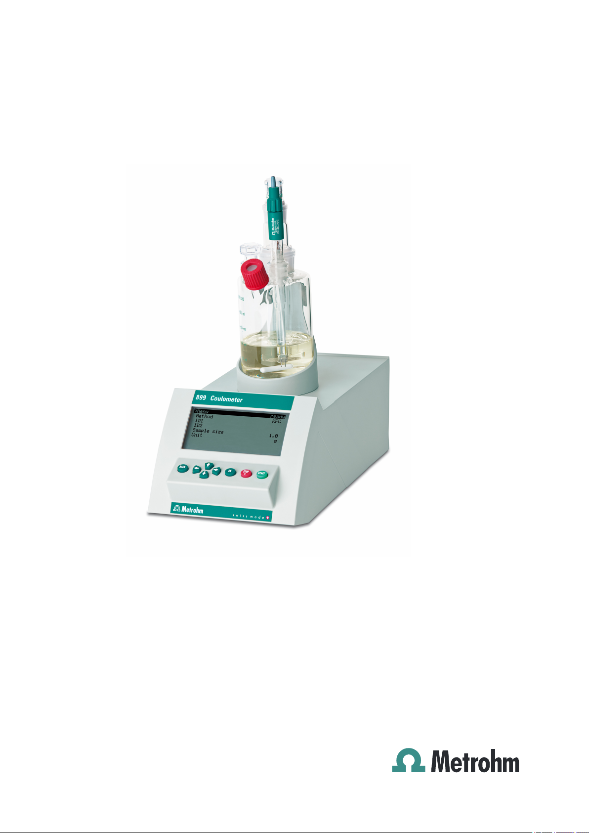
The 899 Coulometer is a titrator used for coulometric water content
determination according to Karl Fischer. There are method templates
available which are already configured except for a few parameters. The
methods can be modified and stored under a new name. The methods
can be exported to a connected USB flash drive. This function makes it
possible for you to copy methods quickly and easily from one instrument
to another.
The 899 Coulometer has an integrated magnetic stirrer that is visible on
the top side of the housing. The coulometer cell can easily be attached to
the magnetic stirrer. Thanks to its compact construction, you can use the
device in a small space as a stand-alone titrator. Furthermore, the remote
interface permits you to connect a sample changer with oven module and
to perform automated determinations.
1 Introduction
As an alternative to the power supply with the power supply unit provided, the 899 Coulometer can also be operated by means of an accumulator (a so-called Power Box). The Power Box is available as optional equipment. It is particularly appropriate for use in environments where power
supplies are either unstable or absent.
1.1.1 Connectors
The instrument is equipped with the following connectors:
■ Electrical connection
■ MSB connector (Metrohm Serial Bus)
■ USB (OTG) connector
■ Sensor connectors
■ Grounding socket
For connecting to the mains supply with the aid of the power supply
unit provided or for connection to the 6.2164.500 Power Box.
For connecting an additional stirrer.
The 6.2151.100 adapter can be used to connect, for example, a
printer, a USB flash drive or a USB keyboard.
Three connectors for the following sensor types:
– Double Pt electrode
– Generator electrode
– Temperature sensor (Pt1000)
For grounding the Coulometer.
899 Coulometer
■■■■■■■■
1
Page 12
1.2 About the documentation
■ Remote connector
For connecting instruments with a remote interface (e.g. 885 Compact
Oven SC).
1.1.2 Intended use
The 899 Coulometer is designed for usage as a titrator in analytical laboratories. Its application field is coulometric water content determination
according to Karl Fischer.
This instrument is suitable for processing chemicals and flammable samples. The usage of the 899 Coulometer therefore requires that the user
have basic knowledge and experience in the handling of toxic and caustic
substances. Knowledge with respect to the application of the fire prevention measures prescribed for laboratories is also mandatory.
1.2 About the documentation
Caution
■■■■■■■■■■■■■■■■■■■■■■
Please read through this documentation carefully before putting the
instrument into operation. The documentation contains information
and warnings which the user must follow in order to ensure safe operation of the instrument.
1.2.1 Symbols and conventions
The following symbols and formatting may appear in this documentation:
Method Dialog text, parameter in the software
File ▶ New Menu or menu item
[Next] Button or key
Cross-reference to figure legend
The first number refers to the figure number, the second to the instrument part in the figure.
Instruction step
Carry out these steps in the sequence shown.
Warning
■■■■■■■■
2
This symbol draws attention to a possible life hazard
or risk of injury.
899 Coulometer
Page 13
■■■■■■■■■■■■■■■■■■■■■■
1 Introduction
Warning
This symbol draws attention to a possible hazard due
to electrical current.
Warning
This symbol draws attention to a possible hazard due
to heat or hot instrument parts.
Warning
This symbol draws attention to a possible biological
hazard.
Caution
This symbol draws attention to a possible damage of
instruments or instrument parts.
Note
This symbol marks additional information and tips.
1.3 Safety instructions
1.3.1 General notes on safety
Warning
This instrument may only be operated in accordance with the specifications in this documentation.
This instrument has left the factory in a flawless state in terms of technical
safety. To maintain this state and ensure non-hazardous operation of the
instrument, the following instructions must be observed carefully.
1.3.2 Electrical safety
The electrical safety when working with the instrument is ensured as part
of the international standard IEC 61010.
Warning
Only personnel qualified by Metrohm are authorized to carry out service
work on electronic components.
899 Coulometer
■■■■■■■■
3
Page 14
1.3 Safety instructions
■■■■■■■■■■■■■■■■■■■■■■
Warning
Never open the housing of the instrument. The instrument could be
damaged by this. There is also a risk of serious injury if live components
are touched.
There are no parts inside the housing which can be serviced or replaced
by the user.
Mains voltage
Warning
An incorrect mains voltage can damage the instrument.
Only operate this instrument with a mains voltage specified for it (see
rear panel of the instrument).
Protection against electrostatic charges
Warning
Electronic components are sensitive to electrostatic charges and can be
destroyed by discharges.
Do not fail to pull the mains cable out of the mains connection socket
before you set up or disconnect electrical plug connections at the rear
of the instrument.
1.3.3 Tubing and capillary connections
Caution
Leaks in tubing and capillary connections are a safety risk. Tighten all
connections well by hand. Avoid applying excessive force to tubing
connections. Damaged tubing ends lead to leakage. Appropriate tools
can be used to loosen connections.
Check the connections regularly for leakage. If the instrument is used
mainly in unattended operation, then weekly inspections are mandatory.
■■■■■■■■
4
899 Coulometer
Page 15
■■■■■■■■■■■■■■■■■■■■■■
1.3.4 Flammable solvents and chemicals
Warning
All relevant safety measures are to be observed when working with
flammable solvents and chemicals.
■ Set up the instrument in a well-ventilated location (e.g. laboratory
flue).
■ Keep all sources of flame far from the workplace.
■ Clean up spilled fluids and solids immediately.
■ Follow the safety instructions of the chemical manufacturer.
1.3.5 Recycling and disposal
This product is covered by European Directive 2002/96/EC, WEEE – Waste
from Electrical and Electronic Equipment.
The correct disposal of your old equipment will help to prevent negative
effects on the environment and public health.
1 Introduction
More details about the disposal of your old equipment can be obtained
from your local authorities, from waste disposal companies or from your
local dealer.
899 Coulometer
■■■■■■■■
5
Page 16
2.1 Front
1
2
3
2 Overview of the instrument
2.1 Front
■■■■■■■■■■■■■■■■■■■■■■
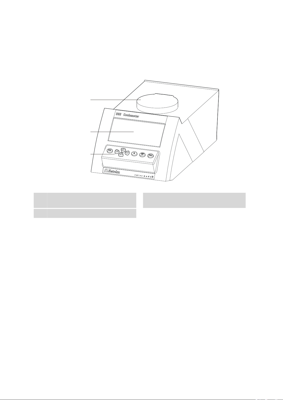
Figure 1 Front 899 Coulometer
Magnetic stirrer
1
For attaching the titration vessel holder.
Keypad
3
2
Display
■■■■■■■■
6
899 Coulometer
Page 17
■■■■■■■■■■■■■■■■■■■■■■
1 2
3
4
5 6
7
8 9
2.2 Rear
2 Overview of the instrument
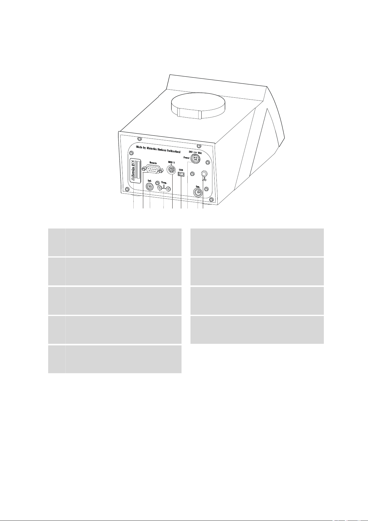
Figure 2 Rear 899 Coulometer
Type plate
1
Contains the serial number.
Electrode connector (Ind.)
3
For connecting a metal electrode (double Pt
wire electrode). Socket F.
MSB connector (MSB 1)
5
Metrohm Serial Bus. For connecting an
external stirrer. Mini DIN, 8-pin.
Mains connection socket (Power)
7
For connecting the external power supply
unit or a Power Box (6.2164.500).
Grounding socket
9
For grounding the Coulometer. Socket B,
4 mm.
Remote connector
2
For connecting instruments with a remote
interface. D-Sub, 9-pin.
Temperature sensor connector (Temp.)
4
For connecting a temperature sensor of the
type Pt1000. Two B sockets, 2 mm.
USB (OTG) connector
6
For connecting printers, USB flash drives,
USB hubs, etc.
Electrode connector (Gen.)
8
For connecting a generator electrode.
899 Coulometer
■■■■■■■■
7
Page 18

3.1 Setting up the instrument
3 Installation
3.1 Setting up the instrument
3.1.1 Packaging
The instrument is supplied in highly protective special packaging together
with the separately packed accessories. Keep this packaging, as only this
ensures safe transportation of the instrument.
3.1.2 Checks
Immediately after receipt, check whether the shipment has arrived complete and without damage by comparing it with the delivery note.
3.1.3 Location
The instrument has been developed for operation indoors and may not be
used in explosive environments.
■■■■■■■■■■■■■■■■■■■■■■
Place the instrument in a location of the laboratory which is suitable for
operation, free of vibrations, protected from corrosive atmosphere, and
contamination by chemicals.
The instrument should be protected against excessive temperature fluctuations and direct sunlight.
■■■■■■■■
8
899 Coulometer
Page 19
■■■■■■■■■■■■■■■■■■■■■■
6.2047.030
6.1464.320
1
2
3.2 Setting up the coulometer cell
3.2.1 Inserting the coulometer cell
3 Installation
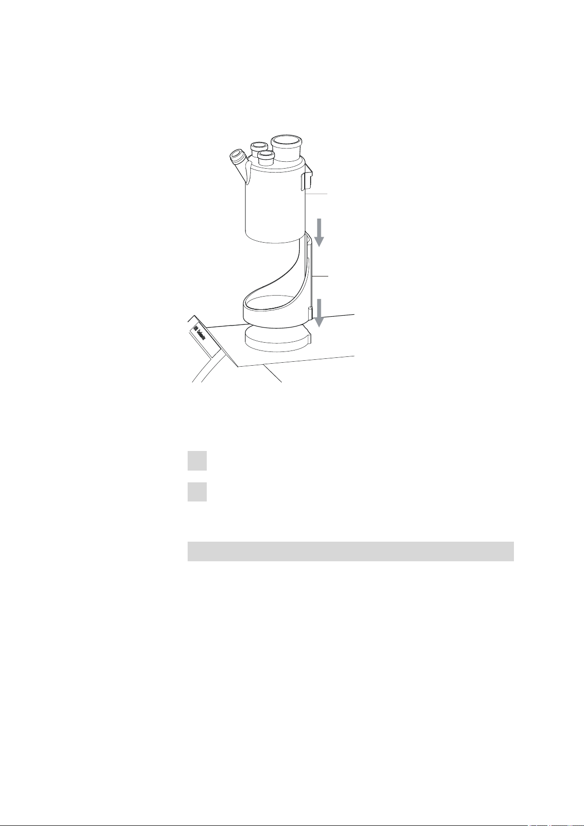
Figure 3 Inserting the coulometer cell
Set up the coulometer cell on the magnetic stirrer as follows:
Attach the 6.2047.030 titration vessel holder to the magnetic stirrer.
1
Insert the 6.1464.320 coulometer cell into the titration vessel holder.
2
3.2.2 Preparing the coulometer cell
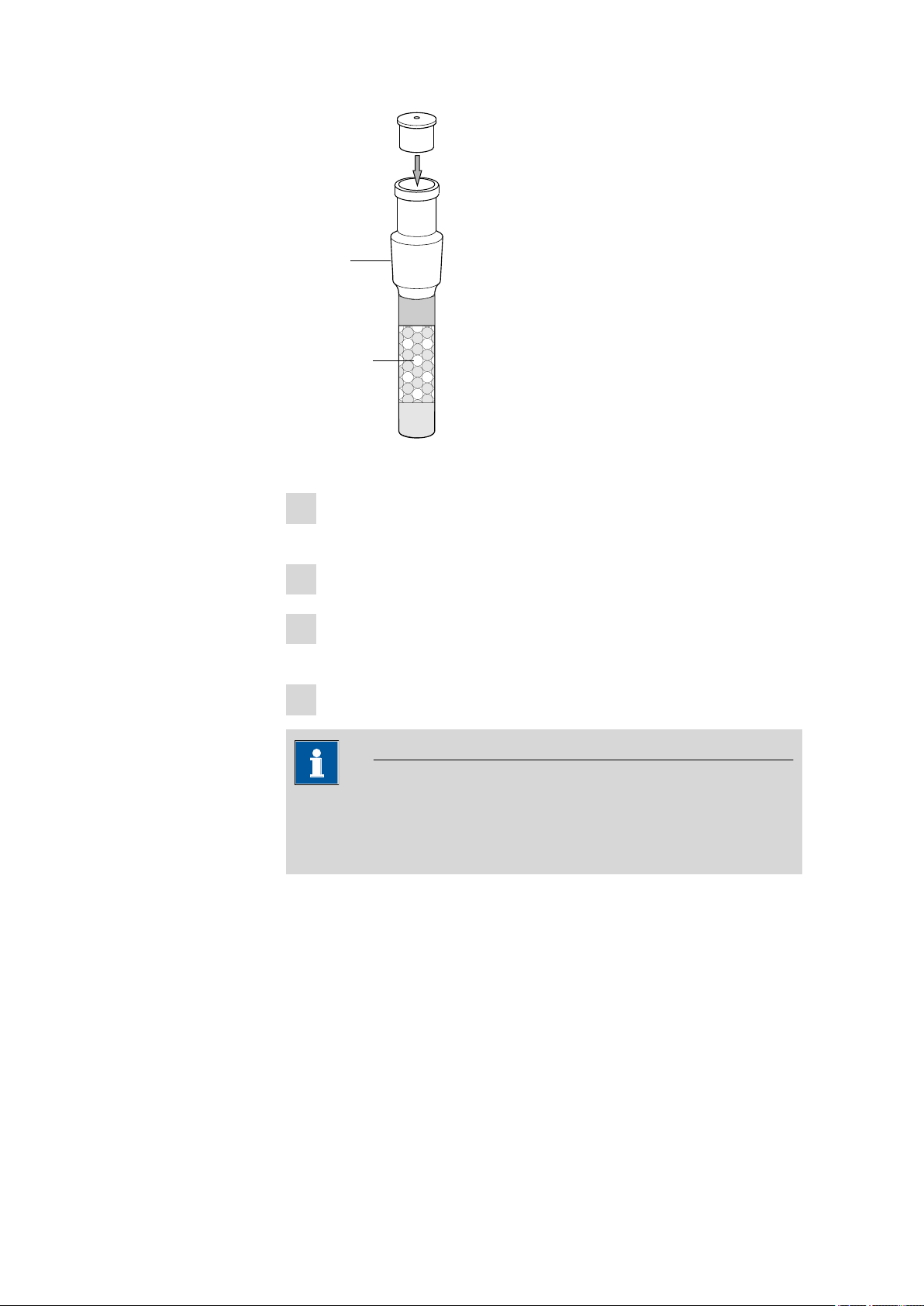
Filling the adsorber tube
Before setting up the coulometer cell the 6.1403.030 adsorber tube has
to be filled with 6.2811.000 molecular sieve. Proceed as follows:
899 Coulometer
■■■■■■■■
9
Page 20
3.2 Setting up the coulometer cell
1
2
3
4
6.1403.030
6.2811.000
■■■■■■■■■■■■■■■■■■■■■■
Figure 4 Filling the adsorber tube
Insert a small cotton plug into the bottom of the adsorber tube. Do
1
not pack the cotton too tightly.
Fill the molecular sieve up to the ¾ level.
2
Place a small cotton plug on the molecular sieve. Do not pack the
3
cotton too tightly.
Seal the adsorber tube with the appropriate cover.
4
Note
Note that the molecular sieve must be replaced at regular intervals.
Each time you refill the adsorber tube with molecular sieve, you can, for
example, write the date directly on the adsorber tube.
■■■■■■■■
10
899 Coulometer
Page 21
■■■■■■■■■■■■■■■■■■■■■■
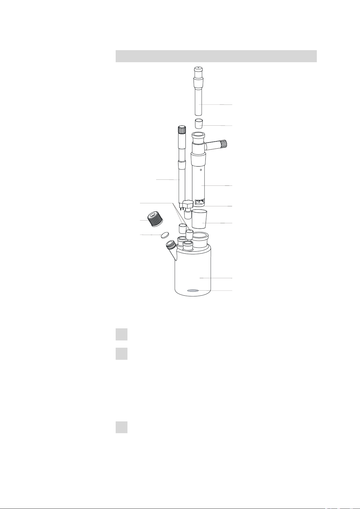
6.1903.030
6.1464.320
6.2713.010
6.1437.000
6.0345.100
6.2713.020
6.1403.030
6.1448.020
6.2701.040
6.2713.000
6.0341.100
2
1
2
5
2
3
4
6
6.0344.100
3 Installation
Equipping the coulometer cell
899 Coulometer
Figure 5 Equipping the coulometer cell
Equip the coulometer cell as follows:
Place the 6.1903.030 stirring bar in the coulometer cell.
1
Cut the 6.2713.0x0 ground-joint sleeves to the correct length and
2
attach them to the ground joints of the inserts (electrodes, adsorber
tube, etc.).
Take care to ensure that the edges of the ground-joint sleeves are
cut to size cleanly and that there are no fringes. The ground-joint
sleeves are not permitted to protrude at the lower edge of the
ground-joint opening.
Insert the 6.1403.030 adsorber tube into the generator electrode.
3
■■■■■■■■
11
Page 22

3.2 Setting up the coulometer cell
■■■■■■■■■■■■■■■■■■■■■■
Insert the 6.0345.100 generator electrode without diaphragm or the
4
6.0344.100 generator electrode with diaphragm together with the
adsorber tube into the large ground-joint opening at the rear.
Insert the 6.0341.100 indicator electrode into the left ground-joint
5
opening.
Place the 6.1448.020 septum on the front opening of the coulome-
6
ter cell and screw it shut with the 6.2701.040 screw cap.
Tighten the screw cap only enough so that it seals. The septum is not
permitted to bend.
Filling the coulometer cell (generator electrode with diaphragm)
Proceed as follows when using a generator electrode with a diaphragm:
Fill approximately 5 mL of catholyte into the generator electrode.
1
Fill approximately 100 mL of anolyte into the coulometer cell with
2
the aid of the 6.2738.000 funnel. The level of the anolyte should be
roughly 1-2 mm above the level of the catholyte.
Close the remaining ground-joint opening on the right with the
3
6.1437.000 ground-joint stopper (with ground-joint sleeve attached).
■■■■■■■■
12
Filling the coulometer cell (generator electrode without
diaphragm)
Proceed as follows when using a generator electrode without a diaphragm:
Fill approximately 100 mL of reagent into the coulometer cell with
1
the aid of the 6.2738.000 funnel.
Close the remaining ground-joint opening on the right with the
2
6.1437.000 ground-joint stopper (with ground-joint sleeve attached).
899 Coulometer
Page 23
■■■■■■■■■■■■■■■■■■■■■■
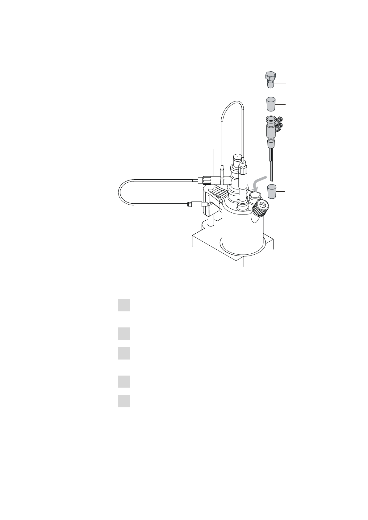
6.1437.000
6.2713.000
6.2713.000
6.1439.010
1
2
4
5
6
3
3 Installation
3.2.3 Mounting the addition and aspiration tube (utilization with Ti Stand)
Figure 6 Mounting the addition and aspiration tube
Insert the addition and aspiration tube as follows into the coulometer cell:
Attach the 6.2713.000 ground-joint sleeve that has been cut to size
1
to the ground joint of the 6.1437.000 stopper.
Insert the stopper into the 6.1439.010 addition and aspiration tube.
2
Attach the 6.2713.000 ground-joint sleeve that has been cut to size
3
to the ground joint of the addition and aspiration tube.
Insert everything together into the ground-joint opening.
4
Connect the tubing for the reagent addition at the upper connector
5
of the addition and aspiration tube (5).
899 Coulometer
■■■■■■■■
13
Page 24

3.3 Connecting the coulometer to the power supply
Connect the tubing for the aspiration of the coulometer cell at the
6
■■■■■■■■■■■■■■■■■■■■■■
lower connector of the addition and aspiration tube (6).
Details regarding how to connect the addition tubing and the aspiration
tubing can be found in the manual for the 803 Ti Stand.
3.2.4 Using the coulometer cell with a Karl Fischer oven
When samples release their water only slowly or only at higher temperatures, the oven method is used. The sample is heated in a KF oven (e.g.
860 KF Thermoprep) and the water that is released is guided with a carrier
gas into the coulometer cell. You will find recommended parameter settings for determinations with a Karl Fischer oven in chapter 10.5, page
97.
A detailed description of setting up the coulometer cell with the KF oven
can be found in the respective manual.
3.2.5 Using the coulometer cell with a sample changer
When there is a large number of samples, the determination of the water
content can be automated with the aid of a sample changer with oven
module (e.g. 885 Compact Oven SC). You will find recommended parameter settings for determinations with a Karl Fischer oven in chapter 10.5,
page 97.
A detailed description of setting up the coulometer cell with the sample
changer can be found in the respective manual.
3.3 Connecting the coulometer to the power supply
You can supply the 899 Coulometer with electricity two different ways:
■ Connect the coulometer directly to the mains supply with the aid of
the power supply unit provided.
■ Connect the coulometer to the 6.2164.500 Power Box if no stable
mains supply is available.
3.3.1 Connecting the power supply unit
The 899 Coulometer has an external power supply unit for a 24 V power
supply (DC). This is connected to the mains connection of the Coulometer.
Warning
An incorrect mains voltage can damage the instrument.
Operate the instrument only with the mains voltage specified for it. Use
the supplied power supply unit exclusively.
■■■■■■■■
14
899 Coulometer
Page 25
■■■■■■■■■■■■■■■■■■■■■■
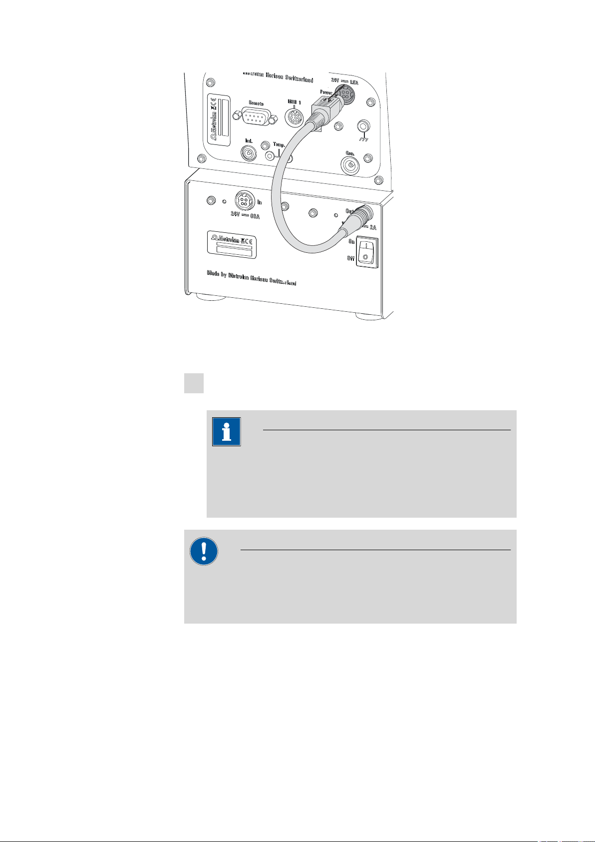
Figure 7 Connecting the power supply unit
Proceed as follows:
Connect the plug of the external power supply unit with the mains
1
connection (2-7) of the Coulometer.
3 Installation
Note
The plug of the power supply unit is protected against accidental
disconnection of the cable by means of a pull-out protection feature. If you wish to pull out the plug, you will first need to pull
back the outer plug sleeve.
Connect the mains cable with the external power supply unit of the
2
Coulometer and with the mains supply.
Caution
Switch off the Coulometer correctly by pressing the red [STOP] key
before you interrupt the electricity supply. If this is not done, then there
is a danger of data loss.
3.3.2 Connecting the Power Box
As an alternative to the power supply from the mains supply, the option
exists of providing the 899 Coulometer with electricity through the
6.2164.500 Power Box. This means that you can also use the instrument
in environments in which no stable mains supply is available. Details
regarding the Power Box can be found in the respective manual.
899 Coulometer
■■■■■■■■
15
Page 26
3.3 Connecting the coulometer to the power supply
Figure 8 Connecting the Power Box
■■■■■■■■■■■■■■■■■■■■■■
Proceed as follows:
Connect the plug of the Power Box with the mains connection (2-7)
1
of the Coulometer.
Note
The Power Box plug is protected against accidental disconnection
of the cable by means of a "pull-out protection" feature. If you
wish to pull out the plug, you will first need to pull back the outer
plug sleeve.
Caution
Switch off the Coulometer correctly by pressing the red [STOP] key
before you interrupt the connection with the Power Box. If this is not
done, then there is a danger of data loss.
■■■■■■■■
16
899 Coulometer
Page 27
■■■■■■■■■■■■■■■■■■■■■■
1
3.4 Connecting sensors
The measuring interface contains the following measuring inputs:
■ Gen. for a generator electrode
■ Ind. for a double Pt electrode
■ Temp. for a temperature sensor of the Pt1000 type
Caution
Under all circumstances, avoid mixing up the electrode cable from the
indicator electrode with the one from the generator electrode. Attach
corresponding markings on the screw heads of the cables.
3.4.1 Connecting a generator electrode
Screwing the electrode cable to the general electrode
3 Installation
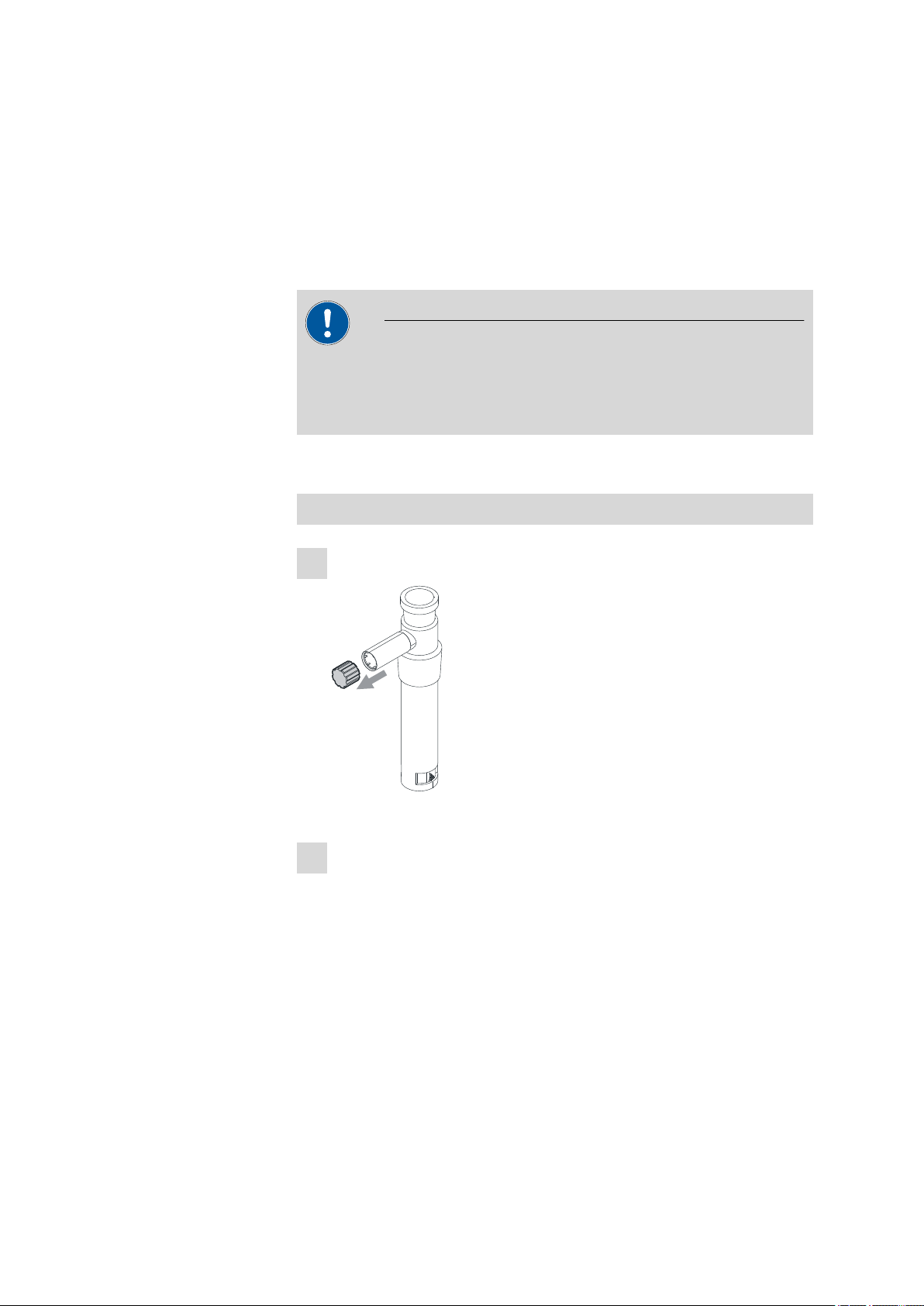
Unscrew the cover of the generator electrode.
1
Figure 9 Unscrewing the cover from the generator electrode
Screw the 6.2104.120 electrode cable tightly onto the generator
2
electrode.
899 Coulometer
■■■■■■■■
17
Page 28
3.4 Connecting sensors
2
6.2104.120
■■■■■■■■■■■■■■■■■■■■■■
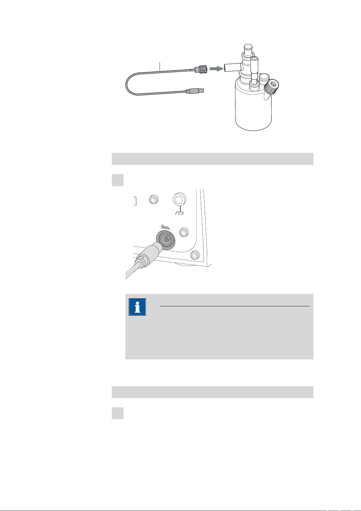
Figure 10 Screwing the electrode cable to the general electrode
Connecting the electrode cable to the coulometer
Plug the electrode plug into the Gen. socket of the Coulometer.
1
Figure 11 Connecting a generator electrode
Note
The electrode cable is protected against accidental disconnection
of the cable by means of a pull-out protection. If you wish to pull
out the plug again, you will first need to pull back the outer plug
sleeve.
3.4.2 Connecting an indicator electrode
Screwing on the electrode cable to the indicator electrode
Unscrew the cover of the indicator electrode.
1
■■■■■■■■
18
899 Coulometer
Page 29
■■■■■■■■■■■■■■■■■■■■■■
1
2
6.2104.020
3 Installation
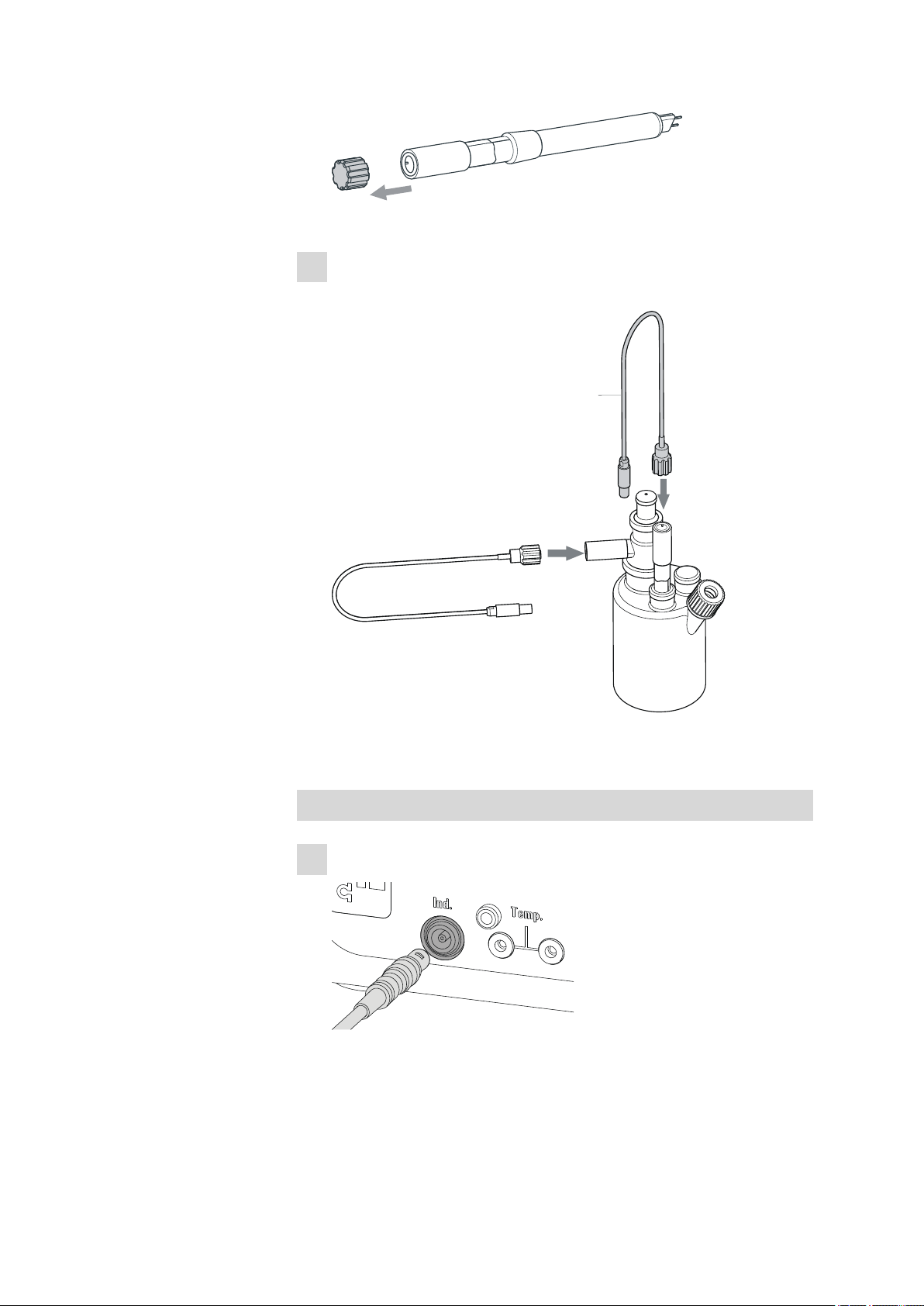
Figure 12 Unscrew the cover from the indicator electrode
Screw the 6.2104.020 electrode cable tightly onto the indicator elec-
2
trode.
Figure 13 Screwing on the electrode cable to the indicator elec-
trode
Connecting the electrode cable to the coulometer
Plug the electrode plug into the Ind. socket of the Coulometer.
1
Figure 14 Connecting an indicator electrode
899 Coulometer
■■■■■■■■
19
Page 30
3.4 Connecting sensors
Note
The electrode cable is protected against accidental disconnection
of the cable by means of a pull-out protection. If you wish to pull
out the plug again, you will first need to pull back the outer plug
sleeve.
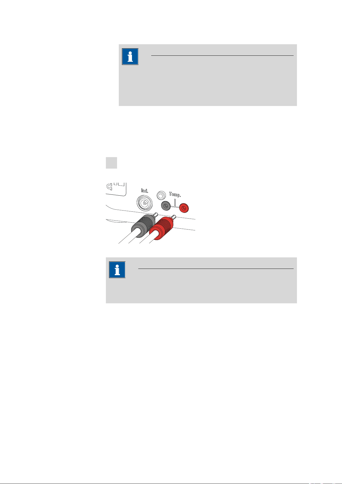
3.4.3 Connecting a temperature sensor
A temperature sensor of the Pt1000 type can be connected to the Temp.
connector.
Connect the temperature sensor as follows:
Insert the plugs of the temperature sensor into the Temp. sockets of
1
the Coulometer.
■■■■■■■■■■■■■■■■■■■■■■
Figure 15 Connecting a temperature sensor
Note
Always insert the red plug into the red socket. It is only this way that
the shielding against electrical interferences is ensured.
■■■■■■■■
20
899 Coulometer
Page 31

■■■■■■■■■■■■■■■■■■■■■■
3.5 Connecting an additional stirrer
Instead of the built-in magnetic stirrer, you can use the magnetic stirrers
801 Stirrer or 803 Ti Stand.
Proceed as follows:
Switch off the Coulometer.
1
Connect the connection cable of the magnetic stirrer to MSB 1 on
2
the rear of the Coulometer.
3 Installation
Figure 16 Connecting a stirrer
Note
Make sure that the flat side of the plug matches the marking on
the socket.
Switch on the Coulometer.
3
899 Coulometer
■■■■■■■■
21
Page 32

3.6 Connecting a balance
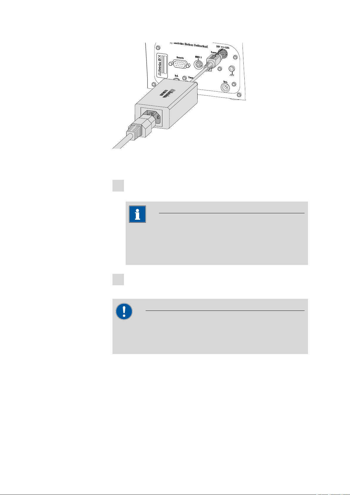
3.6 Connecting a balance
As a rule, balances are equipped with a serial RS-232 interface. To connect a balance, you require a 6.2148.030 RS-232/USB Box.
Figure 17 Connecting the balance via RS-232/USB Box
Proceed as follows:
Connect the RS-232/USB Box with a 6.2151.020 connecting cable
1
(USB A - USB B) on the USB (OTG) connector of the Coulometer.
■■■■■■■■■■■■■■■■■■■■■■
You can connect the RS-232/USB Box either with via a USB hub or
using a 6.2151.100 USB MINI (OTG) - USB A adapter (see Chapter
3.7, page 24) on the Coulometer.
Connect the 9-pin plug of the respective balance connecting cable to
2
the connector RS-232/1. Consult the following list or contact the
scale manufacturer in order to find the correct balance connecting
cable.
Note
The parameters for the RS-232 interfaces on the 899 Coulometer must
match those on the balance (see "Editing the COM1 settings", page
69). Also check the manual for the balance.
The following table offers an overview of the balances that you can use
together with the 899 Coulometer and of which cable you will need for
connection to the RS-232 interface:
■■■■■■■■
22
899 Coulometer
Page 33

■■■■■■■■■■■■■■■■■■■■■■
3 Installation
Balance Cable
AND ER, FR, FX with RS-232 inter-
6.2125.020 + 6.2125.010
face (OP-03)
Mettler AB, AG, PR (LC-RS9) In the scope of delivery for the
balance
Mettler AM, PM, PE with interface
option 016
or
Mettler AJ, PJ with interface
option 018
6.2146.020 + 6.2125.010
also from Mettler: ME 47473
adapter and either ME 42500
hand switch or ME 46278 foot
switch
Mettler AT 6.2146.020 + 6.2125.010
also from Mettler: ME 42500
hand switch or ME 46278 foot
switch
Mettler AX, MX, UMX, PG, AB-S,
6.2134.120
PB-S, XP, XS
Mettler AE with interface option
011 or 012
6.2125.020 + 6.2125.010
also from Mettler: ME 42500
hand switch or ME 46278 foot
switch
Ohaus Voyager, Explorer, Analyti-
Cable AS017-09 from Ohaus
cal Plus
Precisa balances with RS-232-C
6.2125.080 + 6.2125.010
interface
Sartorius MP8, MC, LA, Genius,
6.2134.060
Cubis
Shimadzu BX, BW 6.2125.080 + 6.2125.010
899 Coulometer
■■■■■■■■
23
Page 34

3.7 Connecting a keyboard, printer and other USB devices
6.2151.100
■■■■■■■■■■■■■■■■■■■■■■
3.7 Connecting a keyboard, printer and other USB devices
The 899 Coulometer has a USB (OTG) connector. Use the 6.2151.100
USB MINI (OTG) - USB A adapter supplied for connecting USB devices.
Figure 18 Connecting USB devices
Caution
Switch the instrument off before connecting or disconnecting a USB
device or a USB flash drive.
The 899 Coulometer can recognize the USB device only immediately
after switching on.
Note
Many USB devices need a so-called USB hub in order to work correctly.
A USB hub is a distributor to which several USB devices can be connected. USB hubs are available in specialty stores in a number of different
models.
The 6.2147.000 numerical USB keypad can, in addition to its function
as keyboard, also be used as a USB hub. It has two USB connectors.
You cannot however use these two USB connectors to connect any PC
keyboards, barcode readers or additional keypads with numerical keypads. These devices are recognized as input devices (like the numerical
USB keypad) and they cannot be switched in series.
■■■■■■■■
24
899 Coulometer
Page 35

■■■■■■■■■■■■■■■■■■■■■■
3 Installation
The following list provides you with an overview of the various USB devices and how you can connect them to the Coulometer.
USB device Connection options
USB flash drives (for the backup or
storing of methods)
6.2147.000 numerical USB keypad (for comfortable numerical
input and for navigating in the
dialog)
6.2148.030 RS-232/USB Box (for
connecting a balance, a PC or to
the RS-232 remote control)
USB hub (with or without an own
power supply)
"Custom Neo's" printer with
6.2151.120 cable
"Custom Neo's" printer with
6.2151.020 cable
■ With 6.2151.100 adapter USB
MINI (OTG) - USB A
■ With USB hub
■ With 6.2147.000 numerical
USB keypad
■ With 6.2151.100 adapter USB
MINI (OTG) - USB A
■ With USB hub
■ With 6.2151.100 adapter USB
MINI (OTG) - USB A
■ With USB hub
■ With 6.2147.000 numerical
USB keypad
■ With 6.2151.100 adapter USB
MINI (OTG) - USB A
■ Directly on the USB (OTG) con-
nector of the 899 Coulometer
■ With 6.2151.100 adapter USB
MINI (OTG) - USB A
■ With USB hub
■ With 6.2147.000 numerical
USB keypad
899 Coulometer
USB printer with 6.2151.020 connecting cable
PC mouse with USB cable (for
navigating in the dialog)
Depending on the model of the
printer:
■ With 6.2151.100 adapter USB
MINI (OTG) - USB A
or
■ With USB hub
■ With 6.2147.000 numerical
USB keypad
■ With USB hub
■ With 6.2147.000 numerical
USB keypad
■■■■■■■■
25
Page 36

3.7 Connecting a keyboard, printer and other USB devices
USB MINI (OTG)-USB
USB stick
6.2151.100
USB MINI (OTG)-USB
USB stick
Keypad
6.2147.000
6.2151.100
Printer
USB device Connection options
■■■■■■■■■■■■■■■■■■■■■■
PC keyboard with USB cable (for
■ With USB hub
the comfortable input of letters
and numbers)
Barcode reader with USB cable ■ With USB hub
Keypad with numerical keypad
■ With USB hub
with USB cable
If you wish to connect several different instruments that do not
have their own power supply, then it is possible you will need to use a
USB hub that does have its own power supply (self powered). The USB
(OTG) connector of the 899 Coulometer is not designed for supplying
power to several devices with elevated electricity requirements.
Also observe the instructions in chapter 10.3, page 93.
Examples:
Figure 19
Connecting the USB flash drive
■■■■■■■■
26
Figure 20 Connecting the 6.2147.000 USB keyboard with USB flash
drive and printer
899 Coulometer
Page 37

■■■■■■■■■■■■■■■■■■■■■■
USB MINI (OTG)-USB
USB stick
USB-Hub
RS-232/USB Box
6.2148.030
6.2151.100
Printer
3 Installation
Figure 21 Connecting the USB hub with USB flash drive, printer and
6.2148.030 RS-232/USB Box
3.8 Connecting a sample changer to the remote connector
The 899 Coulometer can be connected to a sample changer with oven
module with the aid of the 6.2141.390 remote cable. This makes it possible to integrate the Coulometer in an automation system.
Figure 22
Connecting a remote cable
Details regarding the use of the sample changer (e.g. 885 Compact Oven
SC) can be found in the respective manual.
899 Coulometer
■■■■■■■■
27
Page 38

4.1 Principle of coulometry according to Karl Fischer
■■■■■■■■■■■■■■■■■■■■■■
4 Coulometric titration
4.1 Principle of coulometry according to Karl Fischer
The coulometric Karl Fischer titration is a variation of the classic
water content determination method according to Karl Fischer. The conventional method works with a methanolic solution of iodine, sulfur dioxide and a base as buffer substance. If an aqueous sample is titrated, then
several reactions take place that can be summarized in the following sum
equation:
H2O + I2 + [RNH]SO3CH3 + 2 RN ⇄ [RNH]SO4CH3 + 2 [RNH]I
According to the equation above the I2 reacts quantitatively with H2O.
This chemical equation serves as a basis for the water content determination.
With the coulometric Karl Fischer titration, the necessary iodine is
directly and electrochemically generated in the electrolyte containing
iodine ("electronic buret"). Between the amount of electric charge and the
amount of generated iodine, there is a strictly quantitative relationship,
which is used for high-precision dosing of the iodine. Because the coulometric Karl Fischer method is an absolute determination, no titer needs
to be determined. It must only be ensured that the reaction generating
the iodine runs with a 100% current efficiency. All of the reagents available today ensure this.
The endpoint indication is effected voltametrically by modulating an alternating current of constant strength to a double Pt electrode. This results in
a voltage differential between the Pt wires. This is drastically reduced as
soon as even the slightest amounts of free iodine are present. This circumstance is used for detecting the endpoint of the titration.
■■■■■■■■
28
899 Coulometer
Page 39

■■■■■■■■■■■■■■■■■■■■■■
4.2 Working with water standards
4.2.1 Certified water standards
For validating the instrument as a whole, integrated system, commercially
available, certified water standards with water contents of 1.00 ± 0.003
mg/g and/or 0.10 ± 0.005 mg/g should be used.
Note
The 1.0 mg/g water standard is easier to handle and therefore to be
preferred.
4 Coulometric titration
Table 1
Recommended sample sizes
Water standard 1.0 mg/g 0.2…2.0 g
Water standard 0.1 mg/g 0.5…5.0 g
4.2.2 Practical recommendations
For validation, it is essential to work very accurately. In order to minimize
any measurement inaccuracies that could occur, the sample preparation
and the sample processing should proceed in accordance with a defined
scheme:
Put on gloves (always with Karl Fischer titration).
1
Use a clean syringe.
2
Note
If you are working with the 0.1 mg/g water standard, then you
must use a glass syringe. If you are working with the 1.0 mg/g
water standard, then you may use either a plastic syringe or a
glass syringe.
899 Coulometer
Take a new ampoule of water standard and shake it briefly.
3
With a folded paper towel held between thumb and index finger,
4
break open the ampoule at the marking.
Draw approx. 1 mL of the water standard into the syringe.
5
■■■■■■■■
29
Page 40

4.2 Working with water standards
■■■■■■■■■■■■■■■■■■■■■■
Pull the piston of the syringe up to the end and swing the syringe
6
back and forth somewhat.
The inside of the syringe is being rinsed by water standard and freed
from water contamination.
Dispose of the used water standard in a waste bottle.
7
Draw the rest of the water standard into the syringe, aspirating as lit-
8
tle air as possible.
Push out any air bubbles that may be present in the syringe.
9
Wipe off the needle with a lint-free paper towel and cover it with the
10
appropriate cap.
Place the syringe on the balance and press [TARA].
11
As soon as the drift on the 899 Coulometer is stable, take the syringe
12
by hand, press [START] and inject approx. 1 mL of the water standard through the septum.
There are two possibilities:
■ Inject the water standard without immersing the needle in the
13
reagent liquid. If a little drop remains on the end of the needle, it
must be aspirated back before pulling the needle out of the septum.
The water standard should not be sprayed from the syringe onto
the electrode nor onto the wall of the coulometer cell.
or
■ Inject the water standard directly under the surface of the reagent
liquid.
Take care to ensure that you do not aspirate any liquid when you
withdraw the syringe out of the reagent liquid.
Close the syringe with the same cap and place it back on the bal-
14
ance.
Read off the value displayed by the balance and enter it on the Coul-
15
ometer as the sample size.
■■■■■■■■
30
899 Coulometer
Page 41

■■■■■■■■■■■■■■■■■■■■■■
If you have connected a balance to the Coulometer, you may transmit the sample size directly from the balance.
The next determination can be started as soon as the determination
16
has been finished and the coulometer cell has been conditioned (drift
stable) again.
4.3 Sample addition
This chapter contains a few notes concerning sample addition. A complete description of this topic is not possible here. Further notes can be
found in the publications from the reagent manufacturers and in the following Metrohm Application Bulletins:
4 Coulometric titration
Bulletin No.
Title
No. 142 Karl Fischer water content determinations in gaseous samples
No. 145 The determination of small water contents in plastics
No. 209 Water content determinations in insulating oils, hydrocarbons and their
products
No. 273 Validation of KF coulometers according to GLP / ISO 9001
4.3.1 Size of the sample size
The sample weight should be small in order to be able to titrate as many
samples as possible in the same electrolyte solution and in order to keep
the titration time short. However, ensure that the sample contains at least
50 µg of H2O. The following table provides clues for the sample size.
Table 2
Recommended sample sizes
Content of the sample Sample size H2O, to be determined
(Water content)
899 Coulometer
10000 ppm = 1% 10 mg…100 mg 100 µg…1000 µg
1000 ppm = 0.1% 100 mg…1 g 100 µg…1000 µg
100 ppm = 0.01% 1 g 100 µg
10 ppm = 0.001% 5 g 50 µg
■■■■■■■■
31
Page 42

4.3 Sample addition
4.3.2 Working with liquid samples
Liquid samples are added with a syringe. The samples can be injected
two different ways:
■ One uses a syringe with a long needle, which one immerses in the
reagent during the injection.
■ One uses a syringe with a short needle and aspirates the last drops
back into the needle.
The best way for you to determine the injected sample amount is to
reweigh the sample.
Glass syringes should be used for the determination of traces and val-
idations. We recommend obtaining these from a specialized syringe
manufacturer.
Highly volatile samples and samples of low viscosity should be
cooled before sampling. Doing so avoids losses while working. The
syringe, however, must not be cooled directly, as condensates could form.
For the same reason, no air may be aspirated into a syringe into which a
cooled sample has been aspirated beforehand.
■■■■■■■■■■■■■■■■■■■■■■
Samples of high viscosity can be thinned by heating. The syringe must
be heated as well. The same target can be reached by diluting with suitable solvents. In this case the water content of the solvent has to be determined and subtracted as blank value.
Paste and fats can be added to the coulometer cell with a syringe without needle. You can use the ground-joint opening for this. If you also wish
to aspirate, you can use the opening with the septum stopper. The best
way for you to determine the sample amount is by reweighing the sample.
If samples contain only traces of water, then the syringe has to be predried well. If possible, the syringe should be rinsed with the sample solution by filling in and discarding solution several times.
4.3.3 Working with solid samples
If possible, solid samples are to be extracted or dissolved in a suitable solvent. The resulting solution is injected, during which a blank value correction for the solvent must be carried out.
If no suitable solvent can be found for a solid sample, or if the sample
reacts with the Karl Fischer reagent, then a Karl Fischer oven should be
used.
■■■■■■■■
32
If solid samples are added directly into the coulometer cell, then the generator electrode without diaphragm should be used. The samples can be
added through the ground-joint opening or through the side opening.
While doing so, take care to ensure that
899 Coulometer
Page 43

■■■■■■■■■■■■■■■■■■■■■■
■ the sample releases its moisture completely.
■ no side reaction with the Karl Fischer reagent takes place.
■ the surfaces of the electrodes are not covered by the sample substance
(incomplete KF reaction).
■ the Pt grid of the generator electrode does not become damaged.
■ the Pt wires of the indicator electrode do not become damaged.
4.4 Optimum working conditions
4.4.1 General
When a coulometer cell that has been well dried-out beforehand is put
into operation with a generator electrode without diaphragm, the basic
drift will be reached within approx. 30 minutes. It is recommended that
the coulometer cell be repeatedly and carefully shaken during this time.
For generator electrodes with diaphragm, you should expect a preparation
time of approx. 2 hours.
To obtain precise determinations of amounts of water smaller than 100
µg, it may also be of advantage to condition the coulometer cell overnight
before using it.
4 Coulometric titration
4.4.2 Drift
If the Coulometer is switched off for extended periods with the coulometer cell filled, it will take some time for it to become conditioned again
after it is switched back on.
With continuous use, the Coulometer should not be switched off overnight.
A constant drift in the range of ≤ 4 µg/min is all right. Lower values, however, are quite possible. Higher but stable values will still produce good
results, because the drift can be compensated.
A constantly high drift can be caused by water-containing deposits in
inaccessible parts of the coulometer cell. In these cases, shaking the cell
can reduce the value. Ensure that there are no drops above the liquid level
in the coulometer cell.
If you are working with a generator electrode with diaphragm, shake the
cell only hard enough that the catholyte and anolyte do not mix with one
another. If the drift remains too high for a prolonged time, even after
shaking the cell, then the electrolyte solutions should be replaced. The
catholyte should be replaced once per week.
899 Coulometer
A wet catholyte can be another reason for the excessively high drift. The
wet catholyte can be dried with a KF single-component reagent.
■■■■■■■■
33
Page 44

4.4 Optimum working conditions
When you work with a Karl Fischer oven, a drift ≤ of 10 µg/min is all right.
The drift depends on the gas flow (the smaller the gas flow, the lower the
drift) and on the humidity of the surroundings.
4.4.3 Reagent replacement
The electrolyte solutions must be replaced in the following cases:
■ The coulometer cell is too full.
■ The KF reagent has reached its capacity limit.
■ The drift is too high, and cannot be reduced by shaking the coulometer
cell.
■ A two-phase-mixture is being formed in the coulometer cell; in this
case it is also possible to aspirate the sample phase only.
Exhausted electrolyte solution is best disposed of by aspiration. To do this,
you can use, for example, an 803 Ti Stand with built-in membrane pump.
An advantage is, that the coulometer cell does not have to be disassembled.
In the event of severe contamination, the coulometer cell can be rinsed
with a suitable solvent which is also aspirated.
■■■■■■■■■■■■■■■■■■■■■■
In the case of the generator electrode with diaphragm, the catholyte
should be replaced once per week. Longer use can cause blackening and
yellow precipitates in the cathode chamber. A discernable stench is also a
sign of having used the catholyte for too long.
4.4.4 Indicator electrode
A new indicator electrode can take a certain warm-up time for forming
the surface. During this time unexpectedly long titration times and high
measurement results can occur. This phenomenon will, however, disappear after a short time of use. In order to accelerate the setting of a new
indicator electrode, the 899 Coulometer can be conditioned e.g. over
night.
A contaminated indicator electrode can be carefully cleaned with an abrasive agent (6.2802.000 polishing set or toothpaste). After the cleaning,
rinse with ethanol.
The two Pt wires of the indicator electrode should run as parallel as possible to one another. Check the Pt wires before inserting the electrode.
■■■■■■■■
34
899 Coulometer
Page 45

■■■■■■■■■■■■■■■■■■■■■■
5 Operation
5.1 Switching the instrument on and off
Switching on the instrument
Proceed as follows:
■ Press the red [STOP] key.
1
The instrument is initialized and a system test performed. This
process takes some time.
The main dialog is displayed:
5 Operation
Switching off the instrument
The instrument is switched off with the [STOP] key. The fact that the key
needs to be pressed down for an extended time prevents accidental
switch off.
Proceed as follows:
■ Keep the red [STOP] key pressed down for at least 3 s.
1
A progress bar is displayed. If the key is released during this time,
then the instrument will not be switched off.
899 Coulometer
■■■■■■■■
35
Page 46

5.2 Fundamentals of operation
5.2 Fundamentals of operation
5.2.1 The keypad
Figure 23 Keypad 899 Coulometer
BACK Apply the input and exit the dialog.
⇧ ⇩ Move the selection bar either up or down by one
line at a time. Select the character to be entered
in the text editor.
⇦ ⇨ Select the character to be entered in the text and
number editor. Select the individual functions in
the function bar.
■■■■■■■■■■■■■■■■■■■■■■
OK Confirm the selection.
STOP Stop an ongoing method run or a manual func-
tion. Switch the instrument on or off.
START Start a method run or a manual function.
5.2.2 Structure of the dialog windows
The current dialog title is displayed on the left-hand side of the title bar.
The current status of the system is displayed in the upper right-hand corner:
ready The instrument is in normal status.
cond.busy The working medium is being conditioned.
cond.ok The working medium is conditioned.
■■■■■■■■
36
busy A method has been started.
hold A method has been paused.
899 Coulometer
Page 47

■■■■■■■■■■■■■■■■■■■■■■
Some dialogs have a so-called function bar on the bottom line. The functions contained therein can be selected with the arrow keys [⇦] or [⇨]
and executed with [OK].
5.2.3 Navigating in the dialog
The selection bar is displayed in inverted style. Use the arrow keys [⇧] and
[⇩] to move the selection bar upward or downward one line at a time. If
a dialog text is marked with ">", then additional settings are available in
a subordinate dialog. Use [OK] to access this dialog.
Example: System settings
5 Operation
Use the [BACK] key to return to the next higher level.
5.2.4 Entering text and numbers
In the editing dialog for text input or numerical input, select the individual
characters with the arrow keys. Use [OK] to apply the character in the
input field. The following functions are available:
Editing function
Accept The modification is applied and the editing dialog
Cancel The editing dialog is exited without applying the
Description
is exited.
modification.
899 Coulometer
■■■■■■■■
37
Page 48

5.2 Fundamentals of operation
■■■■■■■■■■■■■■■■■■■■■■
Editing function Description
Clear The content of the input field is deleted com-
pletely.
The character left of the cursor is deleted (backspace).
Text editor only
The cursor within the input field is shifted to the
left by one character each time that [OK] is
pressed.
Text editor only
The cursor within the input field is shifted to the
right by one character each time that [OK] is
pressed.
[BACK] The modification is applied and the editing dialog
is exited.
The [BACK] key has the same function as Accept.
A commercially available USB keyboard can be connected to make it easier to enter text and numbers. The assignment of the keys on the PC keyboard is described in chapter 10.3.2, page 94.
5.2.5 Selecting from a selection list
In a selection list, select the individual entries with the arrow keys [⇧] and
[⇩]. Accept the selection with [OK] or [BACK].
■■■■■■■■
38
899 Coulometer
Page 49

■■■■■■■■■■■■■■■■■■■■■■
5.3 Formula editor
The formulas for the calculations are entered with the formula editor. The
formula editor is equipped with an automatic syntax check. This is triggered as soon as a formula is applied. The generally valid rules of priority
apply for the calculation operations.
Variable Description
C00 Sample size
EP# Water quantity at the endpoint EP# (# = 1…9)
5 Operation
CI# Sample identification (# = 1…2)
R# Result (# = 1…5)
CV0# Common variable (# = 1…5)
SMN# Mean value of result R# (# = 1…5)
Var List of additional variables (see "Variables", page 39)
"#" stands for a sequential number that you must enter manually. Example: if you apply the variable EP# in the formula, only EP is entered. You
will still need to enter the number yourself.
The meanings of the editing functions are explained in chapter 5.2.4,
page 37.
Variables
Pressing Var displays a list with additional variables. You can enter these
variables either directly into the formula or also by selecting them from the
list and applying them with [OK].
Variable
Description
MCQ End quantity, i.e. total amount of removed water at the
end of the titration (in µg)
899 Coulometer
MCD Duration of the entire titration
MDC Drift for drift correction
■■■■■■■■
39
Page 50

5.4 Methods
Variable Description
DDC Time for drift correction
MIM Initial measured value, i.e. measured value prior to the
MIT Initial temperature, i.e. temperature prior to the process-
MCM End measured value
MCT End temperature
DD Duration of the entire determination
5.4 Methods
5.4.1 Method templates
The 899 Coulometer contains method templates which are already configured except for a few parameters.
■■■■■■■■■■■■■■■■■■■■■■
processing of the start conditions
ing of the start conditions
The following method templates can be selected:
KFC Coulometric Karl Fischer titration.
KFC-Blank Coulometric Karl Fischer titration minus the
Blank Coulometric blank value determination.
The method templates differ only in their calculation formulas.
5.4.2 Loading a method template
Proceed as follows to load a method template:
1
Opening method templates
■ In the main dialog, select Method and press [OK].
The method table with the stored methods opens:
In the function bar, select New and press [OK].
2
The blank value is not taken into account for the
calculation.
blank value.
■■■■■■■■
40
The list with method templates opens:
899 Coulometer
Page 51

■■■■■■■■■■■■■■■■■■■■■■
3
Loading the method template
■ Select the desired method template and press [OK].
The method is now loaded and is displayed in the main dialog under
Method.
5.4.3 Saving a method
If you modify method parameters, then you can save these as your own
method. A maximum of 100 methods can be saved.
To save a method, proceed as follows:
1
Opening the method table
■ In the main dialog, select Method and press [OK].
5 Operation
The method table opens:
2
Modifying/applying the method name
■ In the function bar, select Store and press [OK].
The name of the method template is suggested as the method
name (e.g. KFC-Blank). If the method has already been saved
once, then the method name already used will be displayed:
899 Coulometer
Applying the name:
■■■■■■■■
41
Page 52

5.4 Methods
■ Press [BACK].
The method will be saved and the method table is displayed.
Entering a new name:
■ Press [OK].
The text editor opens.
■ Enter a method name (max. 12 characters) and apply with
Accept or [BACK].
■ Press [BACK].
The method will be saved and the method table is displayed.
5.4.4 Exporting a method
The methods can be exported to a connected USB flash drive.
This function is possible only if a USB flash drive is connected as an
external storage medium.
■■■■■■■■■■■■■■■■■■■■■■
Note
To export a method, proceed as follows:
1
Opening the method table
■ In the main dialog, select Method and press [OK].
The method table with the stored methods opens:
2
Selecting the method
■ Select the desired method.
3
Exporting the method
■ In the function bar, select Export and press [OK].
■■■■■■■■
42
The method is being exported. The directory structure on the USB
flash drive is listed in chapter 6.3, page 66.
899 Coulometer
Page 53

■■■■■■■■■■■■■■■■■■■■■■
5.5 Control
Sample table
Autostart
5 Operation
Menu ▶ Control
In the dialog Control, the settings for the execution of a single determination or of one sample series are defined.
If this parameter is activated, the sample data for a sample series can be
entered in a table (see Chapter 5.7, page 45).
Selection on | off
Default value off
If this parameter is activated, a new determination is started automatically
at the end of a determination. This continues until the number specified
has been reached (see Number of autostarts).
Number of autostarts
Selection on | off
Default value off
Note
If you are working with a sample changer with oven module (e.g. 885
Compact Oven SC), then the Autostart parameter must be set to off,
because the sample changer starts the titration.
This parameter is visible only when Autostart = on.
Number of automatic starts.
Input range 1 ... 50
Selection table
Default value table
table
The number of automatic starts corresponds to the number of samples
in the sample table.
899 Coulometer
■■■■■■■■
43
Page 54

5.6 Sample data
5.6 Sample data
You can enter the sample data (identification, sample size, etc.) in a variety of ways:
■ Directly in the main dialog.
■ Using the sample table. This is particularly useful with sample series.
The sample table is a table in which the sample data for up to 99 samples can be entered (see Chapter 5.7, page 45).
■ Automatic request immediately after the start of the determination (see
Chapter 5.6.2, page 45).
You can also send the sample size and the unit from a connected balance
in any case. With some balances, the sample identification and method
can be also sent (see Chapter 10.2, page 92).
5.6.1 Entering sample data in the main dialog
For a sample, you can enter the sample data directly in the main dialog,
even while the determination is running (see Chapter 5.9, page 52).
■■■■■■■■■■■■■■■■■■■■■■
ID1
ID2
Sample size
Sample identification. The sample identification can be used in calculations
as the variable CI1.
Entry max. 10 characters
Default value empty
Sample identification. The sample identification can be used in calculations
as the variable CI2.
Entry max. 10 characters
Default value empty
Sample size. The value of the sample size can be used in calculations as
the variable C00.
Input range –999999999 ... 9999999999
Default value 1.0
■■■■■■■■
44
899 Coulometer
Page 55

■■■■■■■■■■■■■■■■■■■■■■
Unit
Unit of the sample size.
Selection g | mg | µg | mL | µL | pieces | User-defined
Default value g
User-defined
A user-defined unit can be created. This will be added to the selection
list. The previous entry will be overwritten as soon as the new unit has
been defined.
5.6.2 Requesting sample data at the start of the determination
The sample data can be requested immediately after the start of the determination in order to ensure that the sample data entry is not forgotten.
This automatic request is indispensable when you reweigh your samples.
5 Operation
The corresponding parameters must be activated under Start conditions
for this purpose. If the parameter Hold at request is activated, then the
run will be paused and must be continued with [START] after the input
of the sample data. If Hold at request is deactivated, then the titration
will be started in the background. This dialog will be displayed until the
entering of the sample data is confirmed with [START], even if the the
titration is already completed. This ensures that the sample data is available for calculations.
5.7 Sample table
5.7.1 General
The sample table is a table in which the sample data for up to 99 samples
can be entered. The sample data can also be entered while a determination is running (see Chapter 5.9.2, page 53).
899 Coulometer
■■■■■■■■
45
Page 56

5.7 Sample table
■■■■■■■■■■■■■■■■■■■■■■
Activating the sample table
Proceed as follows to activate the sample table (parameter Sample table
= on).
1
Opening the main menu
■ In the main dialog, select Menu and press [OK].
2
Opening the control dialog
■ Select the menu item Control and press [OK].
3
Activating the sample table
■ Select Sample table and press [OK].
■ Select the entry on in the selection list and apply with [OK].
■ Press [BACK].
The menu item Sample table is displayed in the main menu:
The sample table contains numbered lines. The identification (ID1) and
the sample size of each sample are displayed.
■■■■■■■■
46
899 Coulometer
Page 57

■■■■■■■■■■■■■■■■■■■■■■
Edit
Delete
Insert
New
5 Operation
Edit the data of the selected line, see following chapter.
Delete the selected line from the sample table.
Insert a new line above the line selected.
Delete the sample table completely. This function is visible only if the
instrument is in ready status.
Store
Save the sample table. The sample table is saved in the internal device
memory.
Note
You can save only one sample table. When you save a sample table,
any previously saved sample table will be overwritten automatically.
Load
Load the sample table from the internal device memory.
5.7.2 Editing the sample data
899 Coulometer
You will see at the very bottom the line number of the selected line and
the line number of the last line containing data. In this example, the first
line is opened and the sample table contains four lines.
One can scroll between the individual data sets with the keys [⇦] and [⇨].
■■■■■■■■
47
Page 58

5.7 Sample table
Method
ID1
■■■■■■■■■■■■■■■■■■■■■■
Inserting a new line
If you find yourself on the last line (i.e. Line 4 of 4 in the above example),
you can add a new line to the sample table by pressing [⇨] again. The
sample data of the previous sample will be applied thereby.
Method used for processing the sample.
Selection Selection of stored methods | empty
Default value empty
empty
The currently loaded method is used.
Sample identification. The sample identification can be used in calculations
as the variable CI1.
Entry max. 10 characters
Default value empty
ID2
Sample size
Unit
Sample identification. The sample identification can be used in calculations
as the variable CI2.
Entry max. 10 characters
Default value empty
Sample size. The value of the sample size can be used in calculations as
the variable C00.
Input range –999999999 ... 9999999999
Default value 1.0
Unit of the sample size.
Selection g | mg | µg | mL | µL | pieces | User-defined
Default value g
User-defined
A user-defined unit can be created. This will be added to the selection
list. The previous entry will be overwritten as soon as the new unit has
been defined.
■■■■■■■■
48
899 Coulometer
Page 59

■■■■■■■■■■■■■■■■■■■■■■
5.7.3 Sending the sample size from a balance
If the sample size is sent directly from the balance, then it will always be
entered in a new line at the end of the sample table. It does not matter
which line is selected or whether the sample table is even opened. In the
above example, the sample size is entered in line 5.
Note
If you would like to enter the sample size in a particular line, then you
must open the corresponding editing dialog (i.e. the Sample data dialog is displayed).
5 Operation
If the editing dialog for the sample size is opened, then the sent value
will be ignored.
5.8 Carrying out a determination
The sample size can be entered in the following ways when a determination is carried out:
■ Enter manually on the instrument.
■ Send automatically from a connected balance. For this purpose, check
the manual for the balance.
Proceed as follows to carry out a determination:
1
Loading the method
■ See Chapter "Methods", Page 40.
2
Starting conditioning
■ Press [START].
Conditioning starts. Conditioning not OK is displayed until the
endpoint is reached. The working medium is titrated to the endpoint.
This is indicated by Conditioning OK. The status is kept stable.
899 Coulometer
■■■■■■■■
49
Page 60

5.8 Carrying out a determination
■■■■■■■■■■■■■■■■■■■■■■
The stirring rate can be modified with the Stirrer function. The following dialog is opened by pressing [OK]:
The stirring rate can be reduced with Stir- and increased with Stir+.
Off switches the stirrer off. On is now displayed instead. This can be
used to switch the stirrer back on. This dialog is exited with [BACK].
3
Adding sample
■ If Conditioning OK is displayed, press [START].
Conditioning is stopped. The request for adding the sample will
be displayed for 8 s.
The sample must be added during this time.
■■■■■■■■
50
■ Add the sample.
Afterward, the request for the sample size appears:
899 Coulometer
Page 61

■■■■■■■■■■■■■■■■■■■■■■
4
Entering the sample size
■ Press [OK].
The editing dialog opens.
■ Enter the sample size and apply with Accept or [BACK].
5
Starting the titration
■ Press [START].
The titration starts and the curve is displayed:
The axes are scaled automatically.
5 Operation
The stirring rate can be modified during titration with the Stirrer
function. The following dialog is opened by pressing [OK]:
The stirring rate can be reduced with Stir- and increased with Stir+.
Off switches the stirrer off. On is now displayed instead. This can be
used to switch the stirrer back on. This dialog is exited with [BACK].
After the completion of the titration, the results dialog is displayed:
899 Coulometer
Conditioning is restarted automatically in the background. You can
see the current status of the conditioning in the status display at the
upper right in the dialog window (cond.busy or cond.ok).
■■■■■■■■
51
Page 62

5.9 Live modifications
■■■■■■■■■■■■■■■■■■■■■■
6
Returning to the conditioning dialog
■ Press [BACK].
The main dialog with the sample data of the previously ended
titration is displayed.
■ Select Menu and press [OK].
■ Select the menu item Live dialog and press [OK].
The current status of the conditioning is displayed (see instruction
step 2).
If you wish to start the next titration, repeat the actions starting with
instruction step 3.
Canceling a determination manually
A determination can be canceled at any time with the [STOP] key.
5.9 Live modifications
5.9.1 Editing the sample data of the running determination
The sample data can be entered or modified in the main dialog while a
determination is running. In calculations always the sample data entered
at the end of the titration in the main dialog is used.
Proceed as follows to edit the sample data:
1
Displaying the main dialog
■ Press [BACK].
The main dialog is displayed. The determination continues to run in
the background.
2
Editing the sample data
■ Edit the sample data and apply with Accept or [BACK].
3
Displaying the live dialog
■ Press [BACK].
■■■■■■■■
52
or
899 Coulometer
Page 63

■■■■■■■■■■■■■■■■■■■■■■
5 Operation
■ Select Menu and press [OK].
■ Select the menu item Live dialog and press [OK].
The live dialog is displayed once again.
Note
If the determination is finished while an editing dialog is opened (e.g. of
the sample size), then this will be closed automatically and the results
dialog will be displayed. The value entered must be entered once more
and the determination must be recalculated.
Make sure that the editing dialogs are closed before the determination
is finished.
5.9.2 Editing the sample table while a determination is running
You can insert new lines or delete existing ones or edit sample data while
a determination is running.
Note
We recommend that the editing dialogs always be closed in order to
ensure that no problems occur during the run and that the current data
is always available for calculation purposes.
Editing the sample table
Proceed as follows to edit the sample table:
1
Displaying the main dialog
■ Press [BACK].
The main dialog is displayed. The determination continues to run in
the background.
2
Opening the main menu
■ Select Menu and press [OK].
899 Coulometer
■■■■■■■■
53
Page 64

5.9 Live modifications
■■■■■■■■■■■■■■■■■■■■■■
3
Selecting the sample data
■ Select the menu item Sample table and press [OK].
■ Select the desired line.
■ In the function bar, select Edit and press [OK].
4
Editing the sample data
■ Edit the sample data and apply with Accept or [BACK].
Note
In addition to the sample data, the method can also be modified,
except in cases where the determination is running.
5
Displaying the live dialog
■ Select the menu item Live dialog in the main menu and press
[OK].
or
■ Press [BACK] in the main dialog.
The live dialog is displayed once again.
Editing the sample data of the running determination
When you use the sample table, the editing of the sample data of the running determination proceeds as described in chapter 5.9.1, page 52. In
addition, you have the option of editing these in the sample table. The
first line always contains the sample data of the running determination.
Simply select for this purpose the Sample table(see "Editing the sample
table", page 53) menu item in the main menu.
■■■■■■■■
54
899 Coulometer
Page 65

■■■■■■■■■■■■■■■■■■■■■■
5.9.3 Editing the live parameters
Certain method parameters can be edited while a determination is being
carried out. The only parameters that can be modified are those that can
be selected. Nevertheless, all of the parameters are visible. The modified
parameters are taken into account at once. If, for example, you increase
the parameter Extraction time while the extraction time is still running,
then the new value will be taken into account at once. If however you
change this parameter after the extraction time has already expired, then
the changed value will not be taken into account until the next determination.
Proceed as follows to edit the parameters:
1
Displaying the main dialog
■ Press [BACK].
The main dialog is displayed. The determination continues to run in
the background.
2
Opening the main menu
■ Select Menu and press [OK].
5 Operation
899 Coulometer
3
Editing the method parameters
■ Select the menu item Parameters and press [OK].
■ Change the desired parameters accordingly.
4
Displaying the live dialog
■ Select the menu item Live dialog in the main menu and press
[OK].
or
■ Press [BACK] in the main dialog.
The live dialog is displayed once again.
■■■■■■■■
55
Page 66

5.10 Results
5.10 Results
Curve
■■■■■■■■■■■■■■■■■■■■■■
Menu ▶ Results
After the completion of the titration, the results dialog is displayed:
The calculated result and details concerning the drift and the endpoint are
shown in the overview.
Display the curve of the current determination.
Recalculate
Statistics
Recalculate the current determination. The procedure will be executed
immediately.
Display the statistical overview of a determination series (see Chapter
5.11, page 57).
Displaying the curve
The curve of the current determination can be displayed with the Curve
function.
The arrow keys [⇦] and [⇨] can be used to move to the individual measuring points. A cross hair is used to show the current position on the curve.
The data (water quantity, measured value, time, etc.) for the respective
measuring point is indicated on the right-hand side.
■■■■■■■■
56
899 Coulometer
Page 67

■■■■■■■■■■■■■■■■■■■■■■
Recalculating
All of the results are recalculated with the Recalculate function. This is
necessary if, for example, the calculation or the sample size has been
modified.
5.11 Statistics
Menu ▶ Results ▶ Statistics
The statistical overview of a determination series can be displayed in the
Results dialog with the Statistics function.
5 Operation
Note
Recalculation cannot be undone.
Note
Details
Reset
This function is visible only if statistics has been activated.
The mean value (Mean), the absolute and the relative standard deviation
(s abs and s rel) are displayed in the overview. For the mean value, the
number of individual results from which it has been calculated is displayed
in parentheses. In this example, it is 3. The Statistics line shows how
many determinations have already been carried out and how many determinations are to be carried out in total. All three determinations were carried out in this example.
Display additional data.
Delete all statistics data.
Increase
899 Coulometer
Add a further determination to the determination series.
■■■■■■■■
57
Page 68

5.11 Statistics
On/Off
■■■■■■■■■■■■■■■■■■■■■■
Displaying statistical details
Additional data from the determination series can be displayed with the
Details function.
The result and the sample size of each determination are shown.
Remove the selected determination from the statistics. The line will then
be marked with an asterisk (*), the statistics will be recalculated automatically. If several calculations are defined in the method, then all the results
will be removed from the statistics.
Deleting statistical data
All statistical data is deleted with the Reset function. The statistics data is
deleted automatically in the following cases:
■ When all of the determinations of the determination series have been
carried out and a new determination has been started afterwards.
■ When a new method is loaded.
Adding a determination to a determination series
You can use the function Increase to add an additional sample to a
determination series, e.g. because a determination was faulty and had to
be removed from the statistics. The second number in the Statistics line
will be increased automatically by one.
■■■■■■■■
58
899 Coulometer
Page 69

■■■■■■■■■■■■■■■■■■■■■■
5.12 Printing a report manually
Menu ▶ Print reports
Proceed as follows to print a report manually:
1
Opening the main menu
■ In the main dialog, select Menu and press [OK].
2
Opening the print dialog
■ Select the menu item Print reports and press [OK].
5 Operation
The dialog window with the available reports opens:
3
Selecting the report
■ Select the desired report and press [OK].
The report is printed out.
The following reports can be printed out manually:
Results Result report with determination properties,
sample data, calculated results, etc.
Curve Curve report. The width of the curve is defined in
the system settings (see "Graphics width", page
68).
899 Coulometer
Measuring point
Measuring point list report.
list
Parameters Report with all method parameters of the loaded
method.
■■■■■■■■
59
Page 70

5.13 Manual control
■■■■■■■■■■■■■■■■■■■■■■
System System report with system settings, external
devices, etc.
Calculations/Statistics
PC/LIMS Machine-readable report with all of the data for
Report as in
method
5.13 Manual control
Menu ▶ Manual control
The following function is available in the manual control:
Calculation report. The statistics are also printed
out in the case of multiple determinations. The
individual determinations with the respective
sample size, the mean value, the absolute and
the relative standard deviation are printed out
for each result.
a determination. This report can be saved as a
TXT file to a connected USB flash drive or sent to
a terminal program or a LIMS via an RS-232
interface. The definition is made in the system
settings (see "PC/LIMS report", page 68).
The reports that are defined in the method will
be printed out.
5.13.1 Stirring
■ Stirring
The available subfunctions are listed in the function bar.
Stirrers that are connected or installed in the Coulometer can be controlled manually.
Proceed as follows:
1
Opening the manual control
■ In the main dialog, select Menu and press [OK].
The main menu opens.
■ Select the menu item Manual control and press [OK].
■■■■■■■■
60
Manual control opens.
899 Coulometer
Page 71

■■■■■■■■■■■■■■■■■■■■■■
2
Setting the stirring rate
■
■ In the function bar, select Stir- or Stir+.
The stirring rate will be increased or decreased by one step each
time the [OK] key is pressed.
The algebraic sign changes the direction in which the stirring is
done. When viewing the stirrer from above, this means:
– "+": counterclockwise rotation
– "–": clockwise rotation
3
Switching on the stirrer
■ In the function bar, select On and press [OK].
5 Operation
The stirrer is started and stirs at the rate which has been set. Off is
now displayed in the function bar.
4
Switching off the stirrer
■ In the function bar, select Off and confirm with [OK].
The stirrer is stopped.
899 Coulometer
■■■■■■■■
61
Page 72

6.1 Basic settings
6 System settings
6.1 Basic settings
Menu ▶ System ▶ Settings
This chapter contains a description of general instrument settings.
User name
A user name can be entered here for the report. This parameter will only
be printed if a user has been defined.
Entry max. 12 characters
Default value empty
Instrument name
A instrument name can be entered here for the report. This parameter will
only be printed if a designation has been defined.
■■■■■■■■■■■■■■■■■■■■■■
Serial number
Program version
Time
Date
Language
Entry max. 10 characters
Default value empty
Serial number of the instrument. This is printed as a part of the instrument
identification in the report header.
Version number of the instrument software. This is printed as a part of the
instrument identification in the report header.
Current time. Only valid numbers can be entered.
Format: hh:mm:ss
Current date. Only valid numbers can be entered.
Format: YYYY:MM:DD
Setting the dialog language. An additional language can be selected
besides English.
■■■■■■■■
62
899 Coulometer
Page 73

■■■■■■■■■■■■■■■■■■■■■■
Dialog type
6 System settings
Note
In order to ensure that a second language can be selected, it must first
be installed. This installation must be carried out by specialist personnel.
In chapter Language files, page 71, you will find details regarding the
installation of a second language.
The user dialog can be limited for routine operations. One can operate
normally with methods in the limited dialog. However, no settings can be
made or methods deleted.
The resetting of the dialog will take effect as soon as you exit the main
menu.
The limitation of the dialog results in the following:
■ The menu items System, Parameters and Control are not shown in
the main menu.
■ Methods can only be loaded, but not deleted, exported or created.
Note
If the limited dialog for routine operation is activated, then the expert
dialog cannot be activated during ongoing operation. To change the
dialog type, the 899 Coulometer must be switched off and then back
on again. The expert dialog can be forced as soon as the instrument is
started up again. Then it is possible to enter whatever settings one
wishes, e.g. the changing of the dialog type. If the instrument is
switched off again without changing the dialog type, then the routine
dialog will remain activated.
Forcing the expert dialog:
■ Switch on the instrument.
■ Wait for the display of the instrument logo with the lettering easy,
safe, precise.
■ Press the [STOP] key once again and hold it down while also briefly
pressing the [BACK] key.
■ Release both keys once again.
Selection
Expert | Routine
Default value Expert
899 Coulometer
Expert
Complete dialog.
■■■■■■■■
63
Page 74

6.1 Basic settings
Contrast
■■■■■■■■■■■■■■■■■■■■■■
Routine
Limited dialog for routine operations.
The contrast of the display can be adjusted with the arrow keys [⇦] and
[⇨].
■ [⇦]: the contrast will be decreased by one step each time the key is
pressed.
■ [⇨]: the contrast will be increased by one step each time the key is
pressed.
Input range 150 ... 240
Default value 212
Note
Alternatively, the contrast can also be modified in the following manner:
Beep
Keep the red [STOP] key pressed down. As soon as the progress bar
appears, also press the arrow key [⇩] or [⇧] repeatedly.
This method will, however, cause the contrast to be modified by several
steps.
If this parameter is activated, then a short beep will sound in the following
cases:
■ When a key is pressed.
■ At the end of the determination.
■ When the system remains conditioned without interruption for 10 sec-
onds.
Selection on | off
Default value on
■■■■■■■■
64
899 Coulometer
Page 75

■■■■■■■■■■■■■■■■■■■■■■
6.2 Managing common variables
6.2.1 General
Menu ▶ System ▶ Common variables
The instrument offers the possibility of saving five method-independent
variables, so-called common variables. These variables remain saved in
the instrument and can be used in future calculations. A common variable
is useful, e.g. for the following applications:
■ Determination of a blank value which will be taken into account during
the content determination of the sample.
6 System settings
The common variables have the non-changeable designation CV01…
CV05. The value is displayed for every variable. No unit can be assigned
to the common variables.
Edit
See the following chapter for editing the data of the selected common
variable.
Delete
Set the selected common variable to invalid.
6.2.2 Editing common variables
The common variables can be modified as follows:
■ Manually in this dialog.
■ Automatic assignment from the determination run. A calculation result
must be configured accordingly for this purpose (see below).
Assigning a result automatically to a common variable
Proceed as follows:
1
Opening the editing dialog of the result
899 Coulometer
■ Select the menu item Parameters ▶ Calculation and press
[OK].
■■■■■■■■
65
Page 76

6.3 File management
■■■■■■■■■■■■■■■■■■■■■■
■ Select the result whose value is to be assigned to a common vari-
able.
■ In the function bar, select Edit and press [OK].
2
Adjusting the result properties
■ Select the parameter Save as CV and press [OK].
■ Select the entry on in the selection list and apply with [OK].
The assignment of the result to a common variable occurs automatically
according to the following scheme:
■ Result R1 ⇨ Common Variable CV01
■ Result R2 ⇨ Common Variable CV02
■ etc.
Note
If you have set the parameter Statistics to on, then the mean value of
the results will be assigned to the respective common variable.
6.3 File management
Menu ▶ System ▶ File management
Note
This menu item is visible only if a USB flash drive has been connected as
an external storage medium.
Methods can be imported and deleted from a USB flash drive in this dialog. Only methods located in the Files directory are displayed in the list
(see "Directory structure on the USB flash drive", page 67).
A backup of the system can be created (all data and settings). Similarly, an
existing backup can be reloaded.
Import
■■■■■■■■
66
Import the selected method.
899 Coulometer
Page 77

■■■■■■■■■■■■■■■■■■■■■■
Delete
Backup
Restore
6 System settings
Delete the selected method.
Create a backup of all data and settings on the USB flash drive.
Note
Only one backup can be created on the same USB flash drive.
If a backup is already stored on the flash drive, then this will be overwritten as soon as the function is performed once again.
Load the backup from a connected USB flash drive.
Directory structure on the USB flash drive
A directory with the instrument number will be created on the USB flash
drive. The structure within this directory appears as follows:
Figure 24
Directory structure on the USB flash drive
Backup All of the files of the backup are stored in this
directory. The directory is created as soon as a
backup is created for the first time.
Files Exported methods are stored in this directory.
The directory is created as soon as a backup is
exported for the first time.
Only methods located in this directory can be
imported.
pc_lims_report PC/LIMS reports are stored in this directory as
TXT files. The directory is created as soon as a
PC/LIMS report is printed for the first time.
899 Coulometer
■■■■■■■■
67
Page 78

6.4 Configuring external devices
6.4 Configuring external devices
Menu ▶ System ▶ External devices
PC/LIMS report
Specification of the storage location for the PC/LIMS report. The PC/LIMS
report is a machine-readable report with all of the important data for a
determination. It can be saved as follows:
■ as a TXT file on a USB flash drive.
■ to a LIMS via an RS-232 interface. The 6.2148.030 RS-232/USB Box is
required for this purpose.
Selection COM2 | USB Stick
Default value USB Stick
COM2
The report is sent via the serial COM2 interface. The interface parameters set in the dialog COM2 settings are used (see "Editing the COM2
settings", page 70).
USB Stick
The report will be saved as a TXT file on the USB flash drive in the
folder pc_lims_report.
■■■■■■■■■■■■■■■■■■■■■■
Printer
Graphics width
Keyboard layout
If a printer is connected, then the printer type needs to be defined here in
order for the reports to be printed out correctly.
The printers that have the designation ESC-POS are so-called POS printers
(point-of-sale printers), i.e. they print on continuous paper.
Selection Citizen (ESC-POS) | Custom (ESC-POS) | Epson |
Epson (ESC-POS) | HP DeskJet | HP LaserJet |
Seiko (ESC-POS)
Default value Custom (ESC-POS)
Adjust the width of the curve to be printed out to the paper width of the
printer to be used. The default value depends on the selected printer. The
height of the curve is 2/3 of the width.
Input range 100 ... 3000 Pixels
A commercially available USB keyboard can be connected to make it easier to enter text and numbers. Specify the country-specific keyboard layout.
■■■■■■■■
68
899 Coulometer
Page 79

■■■■■■■■■■■■■■■■■■■■■■
Balance
6 System settings
Selection English US | French FR | German CH | German
DE | Spanish ES
Default value English US
If you have connected a balance, then you must define the balance type
here.
Selection AND | Mettler | Mettler AT | Mettler AX |
Ohaus | Precisa | Sartorius | Shimadzu
Default value Sartorius
The following table indicates the balance type that needs to be selected
for the balance model:
Balance
Balance type
AND AND
Mettler AB, AE, AG, AM,
Mettler
AJ, PE, PM, PJ, PR, XP, XS
Mettler AT Mettler AT
Mettler AX, MX, UMX, PG,
Mettler AX
AB-S, PB-S
Ohaus Voyager, Explorer,
Ohaus
Analytical Plus
Precisa Precisa
Sartorius Sartorius
Shimadzu BX, BW Shimadzu
Editing the COM1 settings
Menu ▶ System ▶ External devices ▶ COM1 settings
The interface parameters for the connected balance are set under COM1
settings.
Baud rate
Data bits
899 Coulometer
Transfer rate in characters per second.
Selection 1200 | 2400 | 4800 | 9600 | 19200 | 38400 |
57600 | 115200
Default value 9600
Number of data bits.
■■■■■■■■
69
Page 80

6.4 Configuring external devices
Stop bits
Parity
Handshake
■■■■■■■■■■■■■■■■■■■■■■
Selection 7 | 8
Default value 8
Number of stop bits.
Selection 1 | 2
Default value 1
Type of parity testing.
Selection even | none | odd
Default value none
Type of the data transfer protocol.
Selection hardware | software | none
Default value hardware
Note
If communications problems occur, set the parameter Handshake to
software, and make another attempt.
Editing the COM2 settings
Menu ▶ System ▶ External devices ▶ COM2 settings
The interface parameters for instruments connected to the RS-232/2 connector of the RS-232/USB Box (e.g. PC) are set under COM2 settings.
The parameters and input ranges are identical to those for the COM1
interface.
■■■■■■■■
70
899 Coulometer
Page 81

■■■■■■■■■■■■■■■■■■■■■■
6.5 Instrument diagnosis
6.5.1 Loading program versions and language files
Menu ▶ System ▶ Diagnosis
New program versions or language files can be loaded from a USB flash
drive. The corresponding file must be saved on the USB flash drive in a
directory with the instrument number (e.g. 899).
You can distinguish between language files and program files by noting
how the file name is constructed.
Program files
They are instrument-specific. The file name has the following structure:
5XXXyyyy.bin where
6 System settings
XXX =
yyyy =
Instrument type (e.g. 899 for the 899 Coulometer)
Program version
Language files
They can be recognized by means of the two-digit language code in the
file name. A language file contains the dialog texts for various instrument
types. It is not instrument-specific. The file name has the following structure:
5848xxxxYY.bin where
xxxx =
YY =
Version number
Language, e.g. DE (German), FR (French), ES (Spanish)
Loading a file
Proceed as follows:
1
Connecting the USB flash drive
■ Plug in the USB flash drive with the 6.2151.100 adapter (USB
MINI (OTG) - USB A) at the instrument's USB port.
■ Switch on the instrument.
2
Opening the update dialog
■ Under Menu ▶ System ▶ Diagnosis, select the menu item
Software update.
■ Press [OK].
899 Coulometer
■■■■■■■■
71
Page 82

6.5 Instrument diagnosis
■■■■■■■■■■■■■■■■■■■■■■
3
Opening the file selection
■ Press [OK].
The selection list with the program and language files present on the
USB flash drive opens.
4
Selecting the file
■ Use the arrow keys to select the required file.
■ Press [OK].
5
Starting the update
■ Press [START].
The update process is started, it runs automatically. At the end of the
process, the instrument will be switched off automatically and
switched back on again. No user intervention is required.
6.5.2 Diagnosis functions
Electronic and mechanical functional groups in Metrohm instruments can
and should be checked as part of regular maintenance by specialist personnel from Metrohm. Please ask your local Metrohm representative
regarding the precise terms and conditions involved in concluding a corresponding maintenance agreement.
■■■■■■■■
72
899 Coulometer
Page 83

■■■■■■■■■■■■■■■■■■■■■■
7 Parameters
7.1 Coulometric Karl Fischer titrations (KFC)
7.1.1 Conditioning
Menu ▶ Parameters ▶ Conditioning
Under Conditioning, the conditions required for conditioning are
defined.
Conditioning
If this parameter is activated, then the first time the titration is started the
working medium will be titrated to the endpoint with the specified control
parameters. The status is kept stable. The actual method run does not
begin until [START] has been pressed once more. Conditioning will be
carried out again automatically after the titration.
7 Parameters
Start drift
Drift correction
Selection on | off
Default value on
If the measured drift is smaller than this value for a certain time (so-called
stabilizing time), then Conditioning OK will be displayed and the titration can be started. The stabilizing time is defined under Condition-
ing ▶ Stabilizing time.
Input range 1 ... 999 µg/min
Default value 20 µg/min
The end point amount can be drift-corrected. To accomplish this, the drift
is multiplied by the drift correction time and this value is subsequently subtracted from the amount of the end point. The drift correction time is the
time interval between the end of conditioning and the end of the determination.
Selection auto | manual | off
Default value auto
auto
The value of the current drift is automatically applied at the start of the
titration.
899 Coulometer
manual
If the drift is known throughout a longer period of time, this can be
entered manually.
■■■■■■■■
73
Page 84

7.1 Coulometric Karl Fischer titrations (KFC)
off
No drift correction takes place.
Drift value
This parameter can only be edited with Drift correction = manual.
Drift for manual drift correction.
Input range 0.0 ... 99.9 µg/min
Default value 0.0 µg/min
Automatic start
If this parameter is activated, then the determination is automatically started when the measured voltage suddenly changes. This setting will be
ignored as long as the working medium has not been conditioned.
Selection on | off
Default value off
■■■■■■■■■■■■■■■■■■■■■■
Note
Threshold value
Stabilizing time
Cond. stop time
If you use the automatic start function, then we recommend that the
start drift be reduced and that a stabilizing time be defined.
Recommendation: Start drift ≤ 10 µg/min / Stabilizing time ≥ 30 s
This parameter can only be edited with Automatic start = on.
If the change in voltage is higher than this value, then the determination
will automatically be started.
Input range 0 ... 999 mV
Default value 50 mV
Waiting time, during which the measured drift has to be smaller than the
start drift defined until Conditioning OK is displayed. The start drift is
defined under Conditioning ▶ Start drift.
Input range 0 ... 999999 s
Default value 0 s
Maximum permissible time over which conditioning may take place. Conditioning is stopped as soon as the specified time has elapsed.
■■■■■■■■
74
Input range 1 ... 999999 s
899 Coulometer
Page 85

■■■■■■■■■■■■■■■■■■■■■■
Selection off
Default value off
Measured value display
If this parameter is activated, then the currently measured value is displayed during the conditioning.
Selection on | off
Default value off
7.1.2 Start conditions
Menu ▶ Parameters ▶ Start conditions
The parameters that are carried out before the start of titration are
defined under Start conditions.
Pause
Waiting time, for example for dissolving the sample. During this time no
iodine is generated.
7 Parameters
Request sample ID
Request sample size
Request sample unit
Input range 0 ... 999999 s
Default value 0 s
Selection of the sample identification that is queried in the method run.
Selection ID1 | ID2 | ID1&ID2 | off
Default value off
If this parameter is activated, then the value for the sample size will be
requested.
Selection on | off
Default value on
If this parameter is activated, then the unit for the sample size will be
requested.
Selection on | off
Default value off
Hold at request
899 Coulometer
If this parameter is activated, then the run will be paused during the
request. If the parameter is deactivated, then the titration will be started in
the background.
■■■■■■■■
75
Page 86

7.1 Coulometric Karl Fischer titrations (KFC)
Selection on | off
Default value on
7.1.3 Control parameters
Menu ▶ Parameters ▶ Control parameters
The control parameters for the endpoint are defined under Control
parameters.
Endpoint at
Measured value for the endpoint.
Input range –1250.0 ... 1250.0 mV
Default value 50.0 mV
Selection off
■■■■■■■■■■■■■■■■■■■■■■
Note
Titration rate
Note that the parameter Endpoint at is linked with the parameters
Dynamics and I(pol). Explanations in this connection can be found in
chapter 10.4 Control parameters and polarization current, page 95.
Three predefined sets of parameters can be selected for the titration rate.
Selection slow | optimal | fast | user
Default value optimal
slow
For samples with a low water content or samples which release their
moisture only slowly.
optimal
For all standard titrations. The parameters have been optimized for the
most frequent applications.
fast
For uncritical samples with high water content.
user
The individual titration parameters can be modified.
The settings of the individual titration rates are listed in table 3, page
77.
Dynamics
■■■■■■■■
76
This parameter can only be edited with Titration rate = user.
899 Coulometer
Page 87

■■■■■■■■■■■■■■■■■■■■■■
7 Parameters
This parameter defines the control range before the specified endpoint.
Within the control range, the iodine is generated step by step, the generation is finely controlled. The closer the endpoint, the slower the iodine is
generated until the rate defined under Min. rate is reached. The larger
the control range, the slower the titration. Outside the control range,
iodine is being continuously generated, the rate is defined under Max.
rate.
Input range 0.1 ... 1250.0 mV
Default value 70.0 mV
Selection off
off
The generation of iodine is finely controlled during the entire titration.
Note
Note that the parameter Dynamics is linked with the parameters Endpoint at and I(pol). Explanations in this connection can be found in
chapter 10.4 Control parameters and polarization current, page 95.
Max. rate
This parameter can only be edited with Titration rate = user.
Rate at which iodine is generated outside the control range.
Input range 1.5 ... 2241.0 µg/min
Selection max.
Default value max.
Min. rate
This parameter can only be edited with Titration rate = user.
Rate at which iodine is generated at the very beginning of the titration
and in the control range at the end of the titration. This parameter has a
decisive influence on the titration rate and thus also on the accuracy. The
smaller the selected minimum rate, the slower the titration.
Input range 0.3 ... 999.9 µg/min
Default value 15.0 µg/min
Table 3 Default values of the predefined titration rates for KFC
Titration rate
slow optimal fast
Dynamics 120.0 mV 70.0 mV 30.0 mV
899 Coulometer
■■■■■■■■
77
Page 88

7.1 Coulometric Karl Fischer titrations (KFC)
■■■■■■■■■■■■■■■■■■■■■■
Titration rate
slow optimal fast
Max. rate 1000.0 µg/min maximum maximum
Min. rate 0.3 µg/min 15.0 µg/min 30.0 µg/min
Stop criterion
The titration is canceled when the endpoint has been reached and this
stop criterion has been fulfilled. If no stop criterion has been selected then
the titration will not be canceled. The stop conditions (see Chapter 7.1.5,
page 81) always lead to a stop, even if the stop criterion has not been
reached.
Selection drift | time | rel. drift | off
Default value rel. drift
drift
The titration is canceled when the stop drift has been reached.
time
The titration is canceled if the endpoint has been exceeded during a
certain time period (Delay time).
rel. drift
The titration is canceled when the sum of the drift at the start of the
titration and the relative stop drift has been reached.
off
The titration will not be canceled until the stop conditions have been
fulfilled.
Stop drift
Delay time
This parameter can only be edited with Stop criterion = drift.
The titration is canceled when the endpoint and the stop drift have been
reached.
Input range 1 ... 999 µg/min
Default value 5 µg/min
This parameter can only be edited with Stop criterion = time.
The titration will be canceled if the following criteria are both met simultaneously.
■ The voltage at the indicator electrode lies in the range "endpoint +5
mV and endpoint –2 mV".
■ The time defined here has expired.
■■■■■■■■
78
899 Coulometer
Page 89

■■■■■■■■■■■■■■■■■■■■■■
If, for example, the parameter Endpoint at is set to 50 mV and the parameter Delay time defined here is 10 s, then the voltage at the indicator
electrode must be between 55 mV and 48 mV for 10 seconds so that the
titration would be canceled.
Input range 0 ... 999 s
Default value 10 s
Relative stop drift
This parameter can only be edited with Stop criterion = rel. drift.
The titration is canceled when the endpoint and the sum of the drift at the
start of the titration and the relative stop drift have been reached.
Input range 1 ... 999 µg/min
Default value 5 µg/min
7.1.4 Titration parameters
Menu ▶ Parameters ▶ Titration parameters
Under Titration parameters, the parameters influencing the sequence
of the entire titration are defined.
7 Parameters
Extraction time
Generator electr.
Generator current
Minimum duration of the titration. The titration will not be canceled during the extraction time, even if the endpoint has already been reached.
The titration is however canceled if a stop condition is fulfilled during this
time (see Chapter 7.1.5, page 81). The entering of an extraction time is
e.g. recommended with samples that release water slowly or if a Karl
Fischer oven is used.
Input range 0 ... 999999 s
Default value 0 s
Type of generator electrode.
Selection with diaphr. | w/o diaphr.
Default value w/o diaphr.
with diaphr.
Generator electrode with diaphragm.
w/o diaphr.
Generator electrode without diaphragm.
Polarization current at the generator electrode.
899 Coulometer
■■■■■■■■
79
Page 90

7.1 Coulometric Karl Fischer titrations (KFC)
Selection 100 mA | 200 mA | 400 mA | auto
Default value 400 mA
400 mA
default value, when Generator electr. = w/o diaphr.
auto
The current is adapted to the conductivity of the reagent and automatically reduced near the endpoint. Default value, when Generator
electr. = with diaphr.
Stirrer
The stirrer is switched on at the start of the determination when this parameter is activated.
Selection on | off
Default value on
Stirring rate
Setting the stirring rate. It can be set in steps of –15 to +15. The default
setting 8 corresponds to 1000 rpm. The formula for calculating the rotational speed is specified in chapter 10.1, page 92. The optimum stirring
rate can be tested in the manual control.
■■■■■■■■■■■■■■■■■■■■■■
I(pol)
The algebraic sign changes the direction in which the stirring is done.
When viewing the stirrer from above, this means:
■ "+": counterclockwise rotation
■ "–": clockwise rotation
Input range –15 ... 15
Default value 8
The polarization current is the current that is applied to a polarizable electrode during the voltametric measurement.
Selection 5 µA | 10 µA | 20 µA | 30 µA
Default value 10 µA
Note
Note that the parameter I(pol) is linked with the parameters Dynamics
and Endpoint at. Explanations in this connection can be found in
chapter 10.4 Control parameters and polarization current, page 95.
■■■■■■■■
80
899 Coulometer
Page 91

■■■■■■■■■■■■■■■■■■■■■■
Electrode test
Time interval MP
Temperature
7 Parameters
In the case of polarizable electrodes, an electrode test can be carried out.
A check is made that the electrode is properly connected and that no
short-circuit is present. The electrode test is carried out as soon as the
determination is started.
Selection on | off
Default value off
Time interval for entering a measuring point in the measuring point list.
The measuring point list is limited to 1000 measuring points.
Input range 0.1 ... 999999.0 s
Default value 2.0 s
Temperature entered manually.
Input range –20.0 ... 150.0 °C
Default value 25.0 °C
7.1.5 Stop conditions
Menu ▶ Parameters ▶ Stop conditions
The conditions for stopping a titration are defined under Stop conditions, if this does not occur automatically. This could be the case when
the endpoint set is not reached or if the stop criterion (see "Stop criterion", page 78) is not fulfilled.
Stop time
The titration is canceled when the specified time has elapsed since the
start of the titration.
Input range 1 ... 999999 s
Selection off
Default value off
7.1.6 Calculation
7.1.6.1
General
Menu ▶ Parameters ▶ Calculation
A maximum of five calculations can be defined in one method. A series of
variables (raw data from the determination, previously calculated results) is
available for the calculations. Definition can be made for each calculation
as to whether the result is to be saved as a common variable.
899 Coulometer
■■■■■■■■
81
Page 92

7.1 Coulometric Karl Fischer titrations (KFC)
The result name is specified in the list for each calculation.
The method templates KFC, KFC-Blank and Blank each contains one
calculation. Each of these calculations already bears an appropriate result
name. You can modify these as needed.
Edit
See the following chapter for editing the data of the selected calculation.
Delete
Delete the selected calculation.
■■■■■■■■■■■■■■■■■■■■■■
7.1.6.2 Editing calculations
Method "KFC"
Result name
The result name is the text which will be shown in the results display and
in the report.
Entry 12 characters
Default value R1: Water / R2-R5: empty
Calculation formula "R1"
R2…R5
Display of the calculation formula. A special editor is opened for the definition (see Chapter 5.3, page 39).
Entry 30 characters
Default value empty
Decimal places
Number of decimal places used to display the result.
EP1/C00
■■■■■■■■
82
Input range 0 ... 5
Default value R1: 1 / R2-R5: 2
899 Coulometer
Page 93

■■■■■■■■■■■■■■■■■■■■■■
Result unit
Save as CV
7 Parameters
The result unit is displayed and saved together with the result.
R1
Selection % | mg | mg/piece | mg/g | mg/mL | ppm | µg |
User-defined
Default value ppm
R2-R5
Selection % | mg | mg/piece | mg/g | mg/mL | ppm | µg |
User-defined
Default value %
User-defined
A user-defined unit can be created. This will be added to the selection
list. The previous entry will be overwritten as soon as the new unit has
been defined. A blank entry can be generated this way as well.
The calculated result can be saved as a method-independent variable, a
so-called common variable. The result is then also available in other methods for calculations. If Statistics has been activated, then the current mean
value of the determination series will be saved.
Result name
R2…R5
Selection on | off
Default value off
Method "KFC-Blank"
The result name is the text which will be shown in the results display and
in the report.
Entry 12 characters
Default value R1: Water / R2-R5: empty
Calculation formula "R1"
(EP1–CV01)/C00
CV01 is the Common Variable 01 and corresponds to the result from the
calculation of the Method "Blank", page 84.
Display of the calculation formula. A special editor is opened for the definition (see Chapter 5.3, page 39).
899 Coulometer
Entry 30 characters
Default value empty
■■■■■■■■
83
Page 94

7.1 Coulometric Karl Fischer titrations (KFC)
Decimal places
Number of decimal places used to display the result.
Input range 0 ... 5
Default value R1: 1 / R2-R5: 2
Result unit
The result unit is displayed and saved together with the result.
R1
Selection % | mg | mg/piece | mg/g | mg/mL | ppm | µg |
Default value ppm
R2-R5
Selection % | mg | mg/piece | mg/g | mg/mL | ppm | µg |
Default value %
User-defined
A user-defined unit can be created. This will be added to the selection
list. The previous entry will be overwritten as soon as the new unit has
been defined. A blank entry can be generated this way as well.
■■■■■■■■■■■■■■■■■■■■■■
User-defined
User-defined
Save as CV
Result name
The calculated result can be saved as a method-independent variable, a
so-called common variable. The result is then also available in other methods for calculations. If Statistics has been activated, then the current mean
value of the determination series will be saved.
Selection on | off
Default value off
Method "Blank"
The result name is the text which will be shown in the results display and
in the report.
Entry 12 characters
Default value R1: Blank / R2-R5: empty
Calculation formula "R1"
EP1
R2…R5
■■■■■■■■
84
Display of the calculation formula. A special editor is opened for the definition (see Chapter 5.3, page 39).
899 Coulometer
Page 95

■■■■■■■■■■■■■■■■■■■■■■
Decimal places
Result unit
7 Parameters
Entry 30 characters
Default value empty
Number of decimal places used to display the result.
Input range 0 ... 5
Default value 2
The result unit is displayed and saved together with the result.
R1
Selection % | mg | mg/piece | mg/g | mg/mL | ppm | µg |
User-defined
Default value µg
R2-R5
Selection % | mg | mg/piece | mg/g | mg/mL | ppm | µg |
User-defined
Default value %
Save as CV
7.1.7 Statistics
User-defined
A user-defined unit can be created. This will be added to the selection
list. The previous entry will be overwritten as soon as the new unit has
been defined. A blank entry can be generated this way as well.
The calculated result can be saved as a method-independent variable, a
so-called common variable. The result is then also available in other methods for calculations. If Statistics has been activated, then the current mean
value of the determination series will be saved.
R1
Selection on | off
Default value on
R2-R5
Selection on | off
Default value off
Menu ▶ Parameters ▶ Statistics
899 Coulometer
The statistics calculation of a multiple determination is activated under
Statistics and definition is made as to how many determinations the series contains.
■■■■■■■■
85
Page 96

7.1 Coulometric Karl Fischer titrations (KFC)
Statistics
If this function is activated, then statistics calculations will be carried out
for all of the defined results.
Selection on | off
Default value off
Number of determinations
The number of determinations that are carried out for the statistics calculations.
If an additional determination has to be added to the determination series, because one determination has been incorrect, for example, then this
can be accomplished in the statistical overview (see Chapter 5.11, page
57).
Input range 2 ... 20
Default value 3
7.1.8 Reports
Menu ▶ Parameters ▶ Reports
■■■■■■■■■■■■■■■■■■■■■■
Results
Curve
Calculations/Statistics
The reports that will be printed out automatically in connection with a
determination are defined under Reports.
The result report contains the calculated results, endpoints, sample data,
etc.
Selection on | off
Default value off
Curve report. The width of the curve is defined in the system settings (see
"Graphics width", page 68).
Selection on | off
Default value off
Output of the calculation formulas for the individual results. Results are
specified with full accuracy. This makes recalculation with an external program possible (see Chapter 10.9, page 103). If Statistics has been activated, then the following data will be printed out as well:
■■■■■■■■
86
■ Result and sample size of the individual determinations
■ Mean value as well as absolute and relative standard deviation
899 Coulometer
Page 97

■■■■■■■■■■■■■■■■■■■■■■
Measuring point list
Parameters
PC/LIMS
7 Parameters
Selection on | off
Default value off
Output of the measuring point list.
Selection on | off
Default value off
All of the parameters of the current method are printed out in the parameter report.
Selection on | off
Default value off
The PC/LIMS report is a machine-readable report with all of the data
important for a determination. The PC/LIMS report can be saved as a TXT
file on a USB storage medium or sent via an RS-232 interface to a LIMS.
The output location is defined in the system settings (see "PC/LIMS
report", page 68).
The file name of the TXT file is constructed as follows: PC_LIMS_Report-
ID1-YYYYMMDD-hhmmss.txt.
Selection on | off
Default value off
899 Coulometer
■■■■■■■■
87
Page 98

8.1 Quality Management and validation with Metrohm
■■■■■■■■■■■■■■■■■■■■■■
8 Operation and maintenance
8.1 Quality Management and validation with Metrohm
Quality Management
Metrohm offers you comprehensive support in implementing quality management measures for instruments and software. Further information on
this can be found in the brochure «Quality Management with
Metrohm» available from your local Metrohm agent.
Validation
Please contact your local Metrohm agent for support in validating instruments and software. Here you can also obtain validation documentation
to provide help for carrying out the Installation Qualification (IQ) and
the Operational Qualification (OQ). IQ and OQ are also offered as a
service by the Metrohm agents. In addition, various application bulletins
are also available on the subject, which also contain Standard Operat-
ing Procedures (SOP) for testing analytical measuring instruments for
reproducibility and correctness.
Maintenance
Electronic and mechanical functional groups in Metrohm instruments can
and should be checked as part of regular maintenance by specialist personnel from Metrohm. Please ask your local Metrohm agent regarding the
precise terms and conditions involved in concluding a corresponding
maintenance agreement.
Note
You can find information on the subjects of quality management, validation and maintenance as well as an overview of the documents currently available at www.metrohm.com/com/ under Support.
■■■■■■■■
88
899 Coulometer
Page 99

■■■■■■■■■■■■■■■■■■■■■■
9 Troubleshooting
9.1 Karl Fischer titration
Problem Cause Remedy
9 Troubleshooting
The drift is very high
during conditioning.
The coulometer cell is not
leak-proof.
Aqueous deposits are to be
found in the coulometer
cell.
The reagent is exhausted
or contaminated.
The catholyte is old or
moist.
The diaphragm of the generator electrode is contaminated.
■ Check the septum and replace it if neces-
sary.
■ Replace the molecular sieve.
■ Check the ground-joint sleeves for frayed
edges. If necessary, trim the edges cleanly
or replace the ground-joint sleeves.
■ Shake the coulometer cell.
■ Replace the reagent.
■ The catholyte must be replaced at least
once per week.
■ Dry the catholyte with KF single-compo-
nent reagent.
■ Clean the diaphragm (in accordance with
directions in the leaflet for the generator
electrode).
The drift becomes
greater after each
titration.
The drift is fluctuating.
899 Coulometer
A side reaction is taking
place.
The molecular sieve on the
KF oven has reached its
capacity limit.
The gas flow from the KF
oven into the coulometer
cell is too high.
The sample releases water
very slowly.
The sample solution is
poorly stirred.
■ Possibly use a KF oven.
■ See technical literature.
■ Replace the molecular sieve.
■ Reduce the gas flow (if you are working
with the oven method with sample vials,
set the gas flow between 40…60 mL/min).
■ Possibly use a KF oven.
■ See technical literature.
■ Set the stirring rate in such a way that the
sample solution will become very well
mixed.
■■■■■■■■
89
Page 100

9.1 Karl Fischer titration
Problem Cause Remedy
■■■■■■■■■■■■■■■■■■■■■■
The titration time is
too long.
The result is too
high.
The Control parameters
are not set correctly.
The drift during conditioning is not stable.
The parameter Start drift
is set too high.
The parameter Stop drift
is set too low.
The water quantity is too
high.
The Control parameters
are set incorrectly.
The coulometer cell is not
yet correctly conditioned.
■ Reset the Control parameters to default
values.
■ Wait before starting the titration until the
drift has become stable.
■ Set the Start drift lower.
■ Adjust the Stop drift or use the Relative
stop drift.
■ Set the Stop drift higher or use the Rela-
tive stop drift.
■ Observe the sample size and water con-
tents in accordance with Table "Recommended sample sizes", page 31.
■ Set the parameter Dynamics lower and
the parameter Max. rate higher.
■ Shake the coulometer cell and wait until
the drift is stable.
The result is too
low.
The sample contains oxidizable substances.
The parameter Stop drift
is set too low.
The drift correction is too
small (e.g. with the use of
a KF oven or with manual
drift correction).
■ Possibly use a KF oven.
■ See technical literature.
■ Set the Stop drift higher or use the Rela-
tive stop drift.
■ Start the titration as long as the gas flow
still exists between the conditioning vial
and the coulometer cell.
■ Set the parameter Drift correction to
auto (= automatic drift correction).
The sample releases iodine. ■ Possibly use a KF oven.
■ See technical literature.
The parameter Stop drift
■ Set the Stop drift lower.
is set too high.
The drift correction is too
large (e.g. with excessively
high start drift, with fluctu-
■ Ensure stable and lower drift.
■ Set the parameter Drift correction to
auto (= automatic drift correction).
ating drift or with manual
drift correction).
■■■■■■■■
90
899 Coulometer
 Loading...