

Page 1
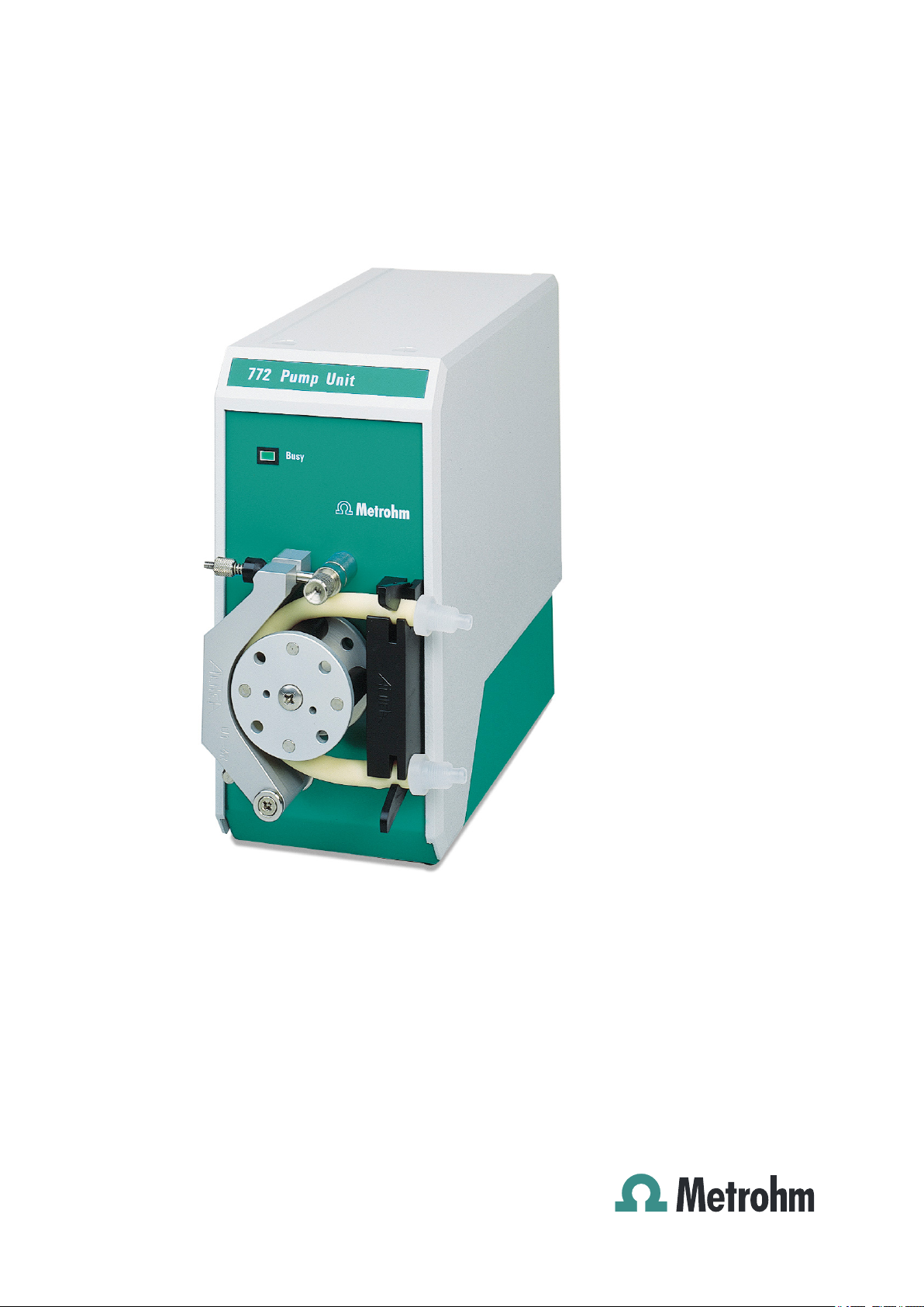
772 Pump Unit
Manual
8.772.8001EN
Page 2

Page 3

Metrohm AG
CH-9100 Herisau
Switzerland
Phone +41 71 353 85 85
Fax +41 71 353 89 01
info@metrohm.com
www.metrohm.com
772 Pump Unit
8.772.8001EN
Manual
07.2012 fpe
Page 4

Teachware
Metrohm AG
CH-9100 Herisau
teachware@metrohm.com
This documentation is protected by copyright. All rights reserved.
Although all the information given in this documentation has been
checked with great care, errors cannot be entirely excluded. Should you
notice any mistakes please send us your comments using the address
given above.
Documentation in additional languages can be found on
http://documents.metrohm.com.
Page 5

■■■■■■■■■■■■■■■■■■■■■■
Table of contents
1 Introduction 1
1.1 Instrument description ......................................................... 1
1.1.1 Model versions ........................................................................ 1
1.1.2 Connectors .............................................................................. 1
1.1.3 Intended use ........................................................................... 1
1.2 About the documentation ................................................... 2
1.2.1 Symbols and conventions ........................................................ 2
1.3 Safety instructions ................................................................ 3
1.3.1 General notes on safety ........................................................... 3
1.3.2 Electrical safety ........................................................................ 3
1.3.3 Tubing and capillary connections ............................................. 4
1.3.4 Flammable solvents and chemicals ........................................... 4
1.3.5 Recycling and disposal ............................................................. 4
2 Overview of the instrument 6
Table of contents
3 Installation 7
3.1 Setting up the instrument .................................................... 7
3.1.1 Packaging ................................................................................ 7
3.1.2 Checks .................................................................................... 7
3.1.3 Location .................................................................................. 7
3.2 Mounting the tubings .......................................................... 7
3.2.1 Mounting the pump tubing ..................................................... 7
3.2.2 Installing the inlet tubing and outlet tubing .............................. 9
3.3 Connecting the peristaltic pump ....................................... 10
3.3.1 Connection to a Sample Processor ......................................... 11
3.3.2 Connection to the 731 Relay Box .......................................... 11
4 Operation 14
5 Operation and maintenance 15
5.1 General notes ...................................................................... 15
5.1.1 Care ...................................................................................... 15
5.1.2 Maintenance by Metrohm Service .......................................... 15
5.2 Pump tubings ...................................................................... 16
5.2.1 Selecting the pump tubing ..................................................... 16
5.2.2 Suitability test for tubing materials ......................................... 17
5.2.3 Tubing dimensions ................................................................. 17
5.2.4 Tubing lifetime ...................................................................... 17
5.2.5 PharMed® pump tubing data sheet ....................................... 18
5.2.6 Viton® pump tubing data sheet ............................................ 19
772 Pump Unit
5.3 Tubings ................................................................................ 20
■■■■■■■■
III
Page 6

Table of contents
■■■■■■■■■■■■■■■■■■■■■■
5.4 Quality Management and validation with Metrohm ....... 20
6 Troubleshooting 21
6.1 Problems ............................................................................. 21
7 Technical specifications 22
7.1 Peristaltic pump .................................................................. 22
7.2 Power supply ...................................................................... 22
7.3 Interfaces and connectors ................................................. 22
7.4 Safety specifications ........................................................... 22
7.5 Electromagnetic compatibility (EMC) ................................ 23
7.6 Ambient temperature ......................................................... 23
7.7 Reference conditions .......................................................... 23
7.8 Dimensions/material ........................................................... 24
8 Conformity and warranty 25
8.1 Quality Management Principles ........................................ 25
8.2 Warranty (Guarantee) ........................................................ 26
9 Accessories 28
9.1 Scope of delivery per model version ................................. 28
9.1.1 772 Pump Unit ...................................................................... 28
9.1.2 772 Pump Unit with aspiration equipment ............................. 29
9.1.3 772 Pump Unit with rinsing equipment .................................. 32
9.2 Optional accessories ........................................................... 35
9.2.1 772 Pump Unit ...................................................................... 35
9.2.2 772 Pump Unit with aspiration equipment ............................. 36
9.2.3 772 Pump Unit with rinsing equipment .................................. 36
Index 38
■■■■■■■■
IV
772 Pump Unit
Page 7

■■■■■■■■■■■■■■■■■■■■■■
Table of figures
Figure 1 Front 772 Pump Unit ......................................................................... 6
Figure 2 Inserting the tubing olives ................................................................. 7
Figure 3 Installing the pump tubing ................................................................ 8
Figure 4 Fastening the pressure clamp in place ................................................ 8
Figure 5 Connecting the tubings ..................................................................... 9
Figure 6 Screwing the union nuts tightly ....................................................... 10
Figure 7 772 Pump Unit directly on the Sample Processor ............................. 11
Figure 8 772 Pump Unit via the Remote Box and 731 Relay Box .................... 12
Figure 9 Direction of rotation ........................................................................ 13
Figure 10 Calculation formula for the permeability (C) ..................................... 19
Table of figures
772 Pump Unit
■■■■■■■■
V
Page 8

Page 9

■■■■■■■■■■■■■■■■■■■■■■
1 Introduction
1.1 Instrument description
The 772 Pump Unit is a versatile peristaltic pump for conveying or evacuating liquid media. It was designed specifically for the production operation and laboratory environment and enables a wide range of applications. Unlike membrane pumps, pumping organic solvents or liquids with
solids content is no problem for the 772 Pump Unit.
Therefore, the 772 Pump Unit is equally well suited for use in titration,
e.g. for evacuating titration samples with silver halide precipitation and as
a delivery pump in larger automation systems. By using the respective suitable tubing material, a wide variety of tasks can be managed.
The flow rate of up to 600 mL/min opens up a wide range of applications.
1.1.1 Model versions
The 772 Pump Unit is available in the following three versions:
1 Introduction
2.772.0110
2.772.0120 772 Pump Unit with aspiration equip-
2.772.0130 772 Pump Unit with rinsing equipment
Each version includes different accessories according to its use (see Chap-
ter 9, page 28).
1.1.2 Connectors
The 772 Pump Unit needs 16 - 24 V DC voltage.
Power is supplied to the pump via the direct connection to a Sample Processor (e.g. 814 or 815) or to the 731 Relay Box (connection via adapter
cable 6.2160.010).
1.1.3 Intended use
The 772 Pump Unit is designed for usage in automated systems in analytical laboratories.
This instrument is suitable for pumping chemicals and flammable samples.
Use of the 772 Pump Unit therefore requires the user to have basic knowledge and experience in handling toxic and caustic substances. Knowledge
with respect to the application of the fire prevention measures prescribed
for laboratories is also mandatory.
772 Pump Unit
ment
772 Pump Unit
■■■■■■■■
1
Page 10
1.2 About the documentation
1.2 About the documentation
Caution
Please read through this documentation carefully before putting the
instrument into operation. The documentation contains information
and warnings which the user must follow in order to ensure safe operation of the instrument.
1.2.1 Symbols and conventions
The following symbols and formatting may appear in this documentation:
Cross-reference to figure legend
The first number refers to the figure number, the second to the instrument part in the figure.
■■■■■■■■■■■■■■■■■■■■■■
Instruction step
Carry out these steps in the sequence shown.
Method Dialog text, parameter in the software
File ▶ New Menu or menu item
[Next] Button or key
Warning
This symbol draws attention to a possible life hazard
or risk of injury.
Warning
This symbol draws attention to a possible hazard due
to electrical current.
Warning
This symbol draws attention to a possible hazard due
to heat or hot instrument parts.
Warning
This symbol draws attention to a possible biological
hazard.
■■■■■■■■
2
Caution
This symbol draws attention to a possible damage of
instruments or instrument parts.
772 Pump Unit
Page 11
■■■■■■■■■■■■■■■■■■■■■■
1.3 Safety instructions
1.3.1 General notes on safety
Warning
This instrument may only be operated in accordance with the specifications in this documentation.
This instrument has left the factory in a flawless state in terms of technical
safety. To maintain this state and ensure non-hazardous operation of the
instrument, the following instructions must be observed carefully.
1.3.2 Electrical safety
The electrical safety when working with the instrument is ensured as part
of the international standard IEC 61010.
1 Introduction
Note
This symbol marks additional information and tips.
Warning
Only personnel qualified by Metrohm are authorized to carry out service
work on electronic components.
Warning
Never open the housing of the instrument. The instrument could be
damaged by this. There is also a risk of serious injury if live components
are touched.
There are no parts inside the housing which can be serviced or replaced
by the user.
Mains voltage
Warning
An incorrect mains voltage can damage the instrument.
772 Pump Unit
Only operate this instrument with a mains voltage specified for it (see
rear panel of the instrument).
■■■■■■■■
3
Page 12
1.3 Safety instructions
Protection against electrostatic charges
Warning
Electronic components are sensitive to electrostatic charges and can be
destroyed by discharges.
Do not fail to pull the mains cable out of the mains connection socket
before you set up or disconnect electrical plug connections at the rear
of the instrument.
1.3.3 Tubing and capillary connections
Caution
Leaks in tubing and capillary connections are a safety risk. Tighten all
connections well by hand. Avoid applying excessive force to tubing
connections. Damaged tubing ends lead to leakage. Appropriate tools
can be used to loosen connections.
■■■■■■■■■■■■■■■■■■■■■■
Check the connections regularly for leakage. If the instrument is used
mainly in unattended operation, then weekly inspections are mandatory.
1.3.4 Flammable solvents and chemicals
Warning
All relevant safety measures are to be observed when working with
flammable solvents and chemicals.
■ Set up the instrument in a well-ventilated location (e.g. fume cup-
board).
■ Keep all sources of flame far from the workplace.
■ Clean up spilled liquids and solids immediately.
■ Follow the safety instructions of the chemical manufacturer.
1.3.5 Recycling and disposal
This product is covered by European Directive 2002/96/EC, WEEE – Waste
from Electrical and Electronic Equipment.
■■■■■■■■
4
The correct disposal of your old equipment will help to prevent negative
effects on the environment and public health.
772 Pump Unit
Page 13

■■■■■■■■■■■■■■■■■■■■■■
1 Introduction
More details about the disposal of your old equipment can be obtained
from your local authorities, from waste disposal companies or from your
local dealer.
772 Pump Unit
■■■■■■■■
5
Page 14
2 Overview of the instrument
1
2
3
4
5
6
7
■■■■■■■■■■■■■■■■■■■■■■
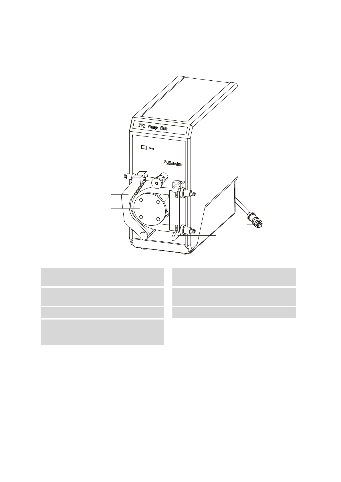
Figure 1 Front 772 Pump Unit
Status LED
1
For displaying the operating state.
Pressure clamp
3
For the counterpressure to the pump tubing.
Tubing clamp (outlet)
5
Connection cable
7
With M8 plug for connection to a Sample
Processor.
Locking lever with clamping screw
2
Rotor
4
Tubing clamp (inlet)
6
■■■■■■■■
6
772 Pump Unit
Page 15

■■■■■■■■■■■■■■■■■■■■■■
3 Installation
3.1 Setting up the instrument
3.1.1 Packaging
The instrument is supplied in highly protective special packaging together
with the separately packed accessories. Keep this packaging, as only this
ensures safe transportation of the instrument.
3.1.2 Checks
Immediately after receipt, check whether the shipment has arrived complete and without damage by comparing it with the delivery note.
3.1.3 Location
The instrument has been developed for operation indoors and may not be
used in explosive environments.
3 Installation
Place the instrument in a location of the laboratory which is suitable for
operation, free of vibrations, protected from corrosive atmosphere, and
contamination by chemicals.
The instrument should be protected against excessive temperature fluctuations and direct sunlight.
3.2 Mounting the tubings
3.2.1 Mounting the pump tubing
Note
Selecting the correct pump tubing is very important for its function and
lifetime (see Chapter 5, page 15).
Cut the pump tubing to a length of approx. 17 cm.
1
Insert the tubing olives (6.1820.050) into the two tubing ends.
2
772 Pump Unit
Figure 2 Inserting the tubing olives
■■■■■■■■
7
Page 16

3.2 Mounting the tubings
1
2
3
4
5
■■■■■■■■■■■■■■■■■■■■■■
Clamp the pump tubing 1 into the pump head according to the
3
drawing below such that the tubing and the tubing olives are fastened by the tubing clips 2 and 3. The tubing must be as centered
on the roller as possible.
Figure 3 Installing the pump tubing
Press on the pressure clamp 5 and fasten it in place using the locking
4
lever 4.
Figure 4 Fastening the pressure clamp in place
Tighten the clamping screw 4 so that the pump tubing cannot slip.
5
With the pump running, gently tighten the clamping screw until the
■■■■■■■■
8
772 Pump Unit
Page 17

■■■■■■■■■■■■■■■■■■■■■■
liquid flows evenly. After a run-in period, correct the setting again if
necessary.
Note
Do not clamp the pump tubing too tightly or apply too much pressure, as this causes greater wear to the pump tubing and the
pump will generate excessive pump pressure.
3.2.2 Installing the inlet tubing and outlet tubing
As the inlet tubing and outlet tubing, two different tubing types are available. Both tubings are included in the scope of delivery .
■ PVC tubing (6.1801.120), 2 x 2 m
■ PTFE tubing (6.1812.000), 1 x 4 m
Note
3 Installation
Which of the two tubings to use depends largely on the solvent used.
PVC tubing is more flexible and has the advantage of making less noise
during the pumping operation. It must be noted that the PVC tubing is
not resistant to solvents.
Install the inlet tubing and outlet tubing as follows:
Cut the inlet tubing and outlet tubing to the suitable length.
1
Connect the tubings to the tubing olives of the pump tubing using
2
union nuts.
772 Pump Unit
Figure 5 Connecting the tubings
■■■■■■■■
9
Page 18

3.3 Connecting the peristaltic pump
■■■■■■■■■■■■■■■■■■■■■■
Note
To fasten PTFE tubings in place, you have to widen their openings
(e.g. using a Phillips screwdriver). You can use a piece of sandpaper to make the PTFE tubing easier to handle.
Do not heat the tubing ends to widen them, as otherwise the connecting nipples can be damaged.
Screw the union nuts tightly to ensure a secure tubing connection.
3
Figure 6 Screwing the union nuts tightly
3.3 Connecting the peristaltic pump
Warning
Follow the instructions listed below for connecting to a control device.
The instrument can be damaged if operated with the wrong supply
voltage.
Voltage
The 772 Pump Unit needs 16 - 24 V DC voltage. It can be connected
directly to Sample Processor models 814, 815, 855 or 864.
When using the 772 Pump Unit in an automation system with remote
control, we recommend using a 731 Relay Box for the power supply.
■■■■■■■■
10
772 Pump Unit
Page 19

■■■■■■■■■■■■■■■■■■■■■■
1 2
3.3.1 Connection to a Sample Processor
■ Plug the M8 plug into the socket on the Sample Processor provided for
this purpose.
3 Installation
Figure 7 772 Pump Unit directly on the Sample Processor
Sample Processor 814, 815, 855, 864
1
Instruments with Pump Connector.
2
Note
The Sample Processor 824 Easy Sample Changer does not have an M8
socket. However, the adapter cable 6.2160.010 can be used for the
connection. For details about connecting the 772 Pump Unit to the
adapter cable, refer to the manual for the 824 Easy Sample Changer.
3.3.2 Connection to the 731 Relay Box
Connect the 772 Pump Unit with connection via the Remote Box
(6.2148.010) and the 731 Relay Box to a remote interface.
■ Connect the M8 plug (1-7) of the 772 Pump Unit to the corresponding
socket on the adapter cable.
■ Plug the adapter cable into low-voltage DC current output DC1 or DC2
of the 731 Relay Box.
772 Pump Unit
Peristaltic pump with M8 connector.
772 Pump Unit
■■■■■■■■
11
Page 20

3.3 Connecting the peristaltic pump
1 2
3
4 5
6
■■■■■■■■■■■■■■■■■■■■■■
Figure 8 772 Pump Unit via the Remote Box and 731 Relay Box
Sample Processor 814, 815, 855, 864
1
Connection via remote interface.
Remote cable (6.2125.100)
3
Adapter cable (6.2160.010)
5
Ensure the correct polarity of the banana plugs.
The red plug (positive pole) belongs in the red socket, the black plug
(negative pole) belongs in the black socket. Reversing the polarity of the
connecting plugs also reverses the direction of pumping.
Note
Remote Box (6.2148.010)
2
731 Relay Box (2.731.0010)
4
772 Pump Unit
6
■■■■■■■■
12
772 Pump Unit
Page 21

■■■■■■■■■■■■■■■■■■■■■■
1
2
3
3 Installation
Figure 9 Direction of rotation
Direction of rotation
1
Correct direction of rotor rotation with correct polarity (clockwise).
Inlet
3
For information on controlling the 772 Pump Unit using the 731 Relay
Box and a suitable control device, refer to the manual of the 731 Relay
Box.
Note
Outlet
2
772 Pump Unit
■■■■■■■■
13
Page 22

4 Operation
■■■■■■■■■■■■■■■■■■■■■■
The 772 Pump Unit does not have its own operating units. It is operated
and controlled via the main instrument in the linked system.
■■■■■■■■
14
772 Pump Unit
Page 23

■■■■■■■■■■■■■■■■■■■■■■
5 Operation and maintenance
5.1 General notes
5.1.1 Care
The 772 Pump Unit requires appropriate care. Excess contamination of the
instrument may result in functional disruptions and a reduction in the lifetime of the sturdy mechanics and electronics.
Spilled chemicals and solvents should be removed immediately. Above all,
the plug connections on the rear of the instrument (in particular the mains
connection socket) should be protected from contamination.
Caution
Although this is extensively prevented by design measures, the mains
plug should be unplugged immediately if aggressive media have penetrated the inside of the instrument, so as to avoid serious damage to
the instrument electronics. In such cases, Metrohm Service must be
informed.
5 Operation and maintenance
5.1.2 Maintenance by Metrohm Service
Maintenance of the 772 Pump Unit is best carried out as part of an annual
service, which is performed by specialist personnel of the Metrohm company. If working frequently with caustic and corrosive chemicals, a shorter
maintenance interval could be necessary.
Metrohm Service offers every form of technical advice for maintenance
and service of all Metrohm instruments.
772 Pump Unit
■■■■■■■■
15
Page 24

5.2 Pump tubings
5.2 Pump tubings
Aggressive liquids
Leaking liquids can pose a risk of injury and damage instruments.
■ Use suitable tubing only.
■ Regularly check tubing for proper fastening and for damage and
wear.
In every case, the user has sole responsibility with regard to suitability
and safety of pump tubing. Therefore, it is extremely important that
before each use, the safety and effectiveness of tubing is tested based
on application-specific laboratory, field or clinical tests.
■■■■■■■■■■■■■■■■■■■■■■
Warning
Note
5.2.1 Selecting the pump tubing
The most important decision when using peristaltic pumps is the selection
of suitable tubing material. Always use tubings particularly intended for
peristaltic pumps.
The 772 Pump Unit is shipped with PharMed® pump tubing (6.1826.100,
ø 6.4/9.6 mm, see Chapter 5.2.5) made of thermoplastic polypropylene,
which is highly suitable for aqueous media.
If you need other tubings for your application, take care to ensure the following points when evaluating the pump tubings:
■ Chemical resistance
■ Pressure build-up in the pump tubing
■ Sterilizability
■ Temperature of the pump medium and the environment
■ Viscosity of the liquid
■ Permeability of the pump tubing
■ Demanded flow rate
■ Tubing dimensions
We recommend using PVC, silicone, Viton® and PharMed® as the tubing
materials. Contact your laboratory dealer for information on suitable products and their data sheets.
■■■■■■■■
16
772 Pump Unit
Page 25

■■■■■■■■■■■■■■■■■■■■■■
5.2.2 Suitability test for tubing materials
Place a piece of the tubing in question for 48 hours in a closed container
filled with the liquid in question. Then examine the piece of tubing for
signs of swelling, embrittlement or other damage.
5.2.3 Tubing dimensions
Note
Use tubing with a wall thickness of 1.6 mm only.
The largest usable inner diameter is 6.4 mm.
5.2.4 Tubing lifetime
The pump tubing has a limited lifetime and therefore has to be replaced
regularly. The following are examples of factors that can influence the lifetime of tubing in peristaltic pumps:
5 Operation and maintenance
■ Chemical resistance of the pump tubing
■ Pump rate (rotational speed)
■ Properties of the pumped liquid
■ Outlet pressure
■ Ambient temperature
■ Shearing force of the rollers
■ Twisted or kinked tubing
■ Tubing too long
■ Wall thickness of 1.6 mm not complied with
772 Pump Unit
■■■■■■■■
17
Page 26

5.2 Pump tubings
■■■■■■■■■■■■■■■■■■■■■■
Note
■ If the tubing is not tightened sufficiently around the rotor, this has a
negative impact on the lifetime of the tubing, as in this case the tubing tends to fold up. If the tubing is tightened too much, the flow is
restricted.
■ The tubing will last longer if the pressure clamp is detached when
the pump is not in use.
■ In order to achieve good repeatability of flow rate following a
change in tubing, it is imperative that you always select the same
tubing length.
Before changing tubing:
■ Pump all of the liquid out of the tubing so that none remains.
■ Pull out the connection cable of the peristaltic pump to prevent acci-
dental starting of the pump.
■ Detach the pressure clamp, open the tubing clamps and remove the
tubing.
5.2.5 PharMed® pump tubing data sheet
Physical properties Polypropylene-based thermoplastic elastomer, contains
plasticizer
Dimensions Inner diameter = 6.4 mm
Wall thickness 1.6 mm
Advantages Ideal for aqueous media
Impermeable to normal light and UV radiation
Tubing can be welded, glued and thermoformed.
Very long lifetime
Restrictions Additives can be dissolved out by the pumped medium.
Applications: Acids
Bases
Solvents
Pressure
Vacuum
Viscous media
Sterile media
Good resistance
Good resistance
Not suitable
Well suited
Very well suited
Well suited
Very well suited
■■■■■■■■
18
Temperature range –60 - +130 °C
772 Pump Unit
Page 27

■■■■■■■■■■■■■■■■■■■■■■
5 Operation and maintenance
Permeability (C) for:
(see Figure 10, page 19)
CO
O
N
Corresponds to the following standards:
USP Class VI
FDA 21CFR177.2600
NSF (Standard 51)
Cleaning/sterilization The tubing can be sterilized in the autoclave without
being damaged.
Figure 10 Calculation formula for the permeability (C)
5.2.6 Viton® pump tubing data sheet
Physical properties Viton®; rigid, impermeable, black
Dimensions Inner diameter = 6.4 mm
Wall thickness 1.6 mm
2
2
2
1,200
200
80
Advantages High chemical resistance
Low gas permeability
Wide temperature range
Restrictions Limited lifetime
Applications: Acids
Bases
Solvents
Pressure
Vacuum
Viscous media
Sterile media
Temperature range –31 °C - +204 °C
Permeability (C) for: CO
Corresponds to the fol-
O
2
N
2
None
2
lowing standards:
Outstanding
Outstanding
Limited
Not recommended
Good
Good
Satisfactory
38
14
5
772 Pump Unit
Cleaning/sterilization Not recommended
■■■■■■■■
19
Page 28

5.3 Tubings
■■■■■■■■■■■■■■■■■■■■■■
5.3 Tubings
The tubing requires regular inspection in order to work properly:
■ Do not kink PTFE tubing.
■ Ensure resistance to solvents.
■ Check the tubing regularly for any damage.
5.4 Quality Management and validation with Metrohm
Quality Management
Metrohm offers you comprehensive support in implementing quality management measures for instruments and software. Further information on
this can be found in the brochure «Quality Management with
Metrohm» available from your local Metrohm agent.
Validation
Please contact your local Metrohm agent for support in validating instruments and software. Here you can also obtain validation documentation
to provide help for carrying out the Installation Qualification (IQ) and
the Operational Qualification (OQ). IQ and OQ are also offered as a
service by the Metrohm agents. In addition, various application bulletins
are also available on the subject, which also contain Standard Operat-
ing Procedures (SOP) for testing analytical measuring instruments for
reproducibility and correctness.
Maintenance
Electronic and mechanical functional groups in Metrohm instruments can
and should be checked as part of regular maintenance by specialist personnel from Metrohm. Please ask your local Metrohm agent regarding the
precise terms and conditions involved in concluding a corresponding
maintenance agreement.
Note
You can find information on the subjects of quality management, validation and maintenance as well as an overview of the documents currently available at www.metrohm.com/com/ under Support.
■■■■■■■■
20
772 Pump Unit
Page 29

■■■■■■■■■■■■■■■■■■■■■■
6 Troubleshooting
6.1 Problems
Problem Cause Remedy
6 Troubleshooting
The flow is not set
correctly.
The liquid is not
aspirated, but just
"bubbles" instead.
The peristaltic pump
is not running.
The peristaltic pump
is pumping too little
or not at all.
The tubing connection of the inlet tubing and/or outlet
tubing is dripping.
The flow is too strong or
too weak.
The inlet tubing and the
outlet tubing have been
switched.
The connecting cable is not
connected.
The pressure clamp is set
insufficiently or not at all.
The tubing clamp is pinching off the tubing.
The tubings are not
screwed on correctly.
Loosen or tighten the locking lever with the
clamping screw.
Switch the tubings so that the inlet tubing
goes into the solution and the outlet tubing
goes into the waste canister.
Connect the connecting cable.
Set the correct pressure using the locking lever
and clamping screw.
Fasten the tubing end piece and the tubing
olive in the tubing clip correctly. The tubing
clamp must clamp the tubing in the area of
the tubing olive.
Check the screw connectors.
The tubing connection of the pump
tubing is dripping or
spraying.
772 Pump Unit
The pressure is too high. Loosen the locking lever of the pressure clamp
slightly.
If necessary, also use a cable tie to tie down
the cable ends at the tubing olives.
■■■■■■■■
21
Page 30

7.1 Peristaltic pump
7 Technical specifications
7.1 Peristaltic pump
■■■■■■■■■■■■■■■■■■■■■■
Direction of rota-
Clockwise
tion
Rotational speed 160 - 250 rpm, at 20 V / 200 mA
Flow rate 400 - 600 mL/min
(depending on the supply voltage and the selection of pump tubing)
Pump tubings
Wall thickness 1.6 mm
Inner diameter 0.8 - 6.4 mm
Material Depending on the medium.
7.2 Power supply
Voltage
Power consumption
16 - 24 V DC
≤ 550 mA
7.3 Interfaces and connectors
The 772 Pump Unit does not have any control interfaces. It is operated
and controlled via the power supply.
7.4 Safety specifications
This instrument fulfills the following electrical safety requirements:
CE designation in accordance with the EU directives:
■ 2006/95/EC (Low Voltage Directive, LVD)
■ 2004/108/EC (EMC Directive, EMC)
Design and testing ■ EN/IEC/UL 61010-1
■ CSA-C22.2 No. 61010-1
■ Protection class III
■ EN/IEC 60529
■ Degree of protection IP20
Safety instructions This document contains safety instructions which have to be followed
by the user in order to ensure safe operation of the instrument.
■■■■■■■■
22
772 Pump Unit
Page 31

■■■■■■■■■■■■■■■■■■■■■■
7.5 Electromagnetic compatibility (EMC)
Emission
Standards fulfilled
Immunity
Standards fulfilled
■ EN/IEC 61326-1
■ EN/IEC 61000-6-3
■ EN 55011 / CISPR 11
■ EN/IEC 61326-1
■ EN/IEC 61000-6-2
■ EN/IEC 61000-4-2
■ EN/IEC 61000-4-3
■ EN/IEC 61000-4-4
■ EN/IEC 61000-4-5
■ EN/IEC 61000-4-6
■ EN/IEC 61000-4-11
■ EN/IEC 61000-4-14
■ EN/IEC 61000-4-28
7 Technical specifications
7.6 Ambient temperature
Nominal function
range
Transport and
storage
+5 - +45 °C
–40 - +70 °C
7.7 Reference conditions
Ambient temperature
Relative humidity ≤ 60%
+25 °C (±3 °C)
772 Pump Unit
■■■■■■■■
23
Page 32

7.8 Dimensions/material
7.8 Dimensions/material
Width 100 mm
Height 210 mm
Depth 260 mm
Weight 3.20 kg (without accessories)
Material
Housing, upper
part
Bottom part of
housing
Polyurethane, coated
Steel sheet, stove-enameled
■■■■■■■■■■■■■■■■■■■■■■
■■■■■■■■
24
772 Pump Unit
Page 33

■■■■■■■■■■■■■■■■■■■■■■
8 Conformity and warranty
8.1 Quality Management Principles
Metrohm Ltd. holds the ISO 9001:2000 Certificate, registration number
10872-02, issued by SQS (Swiss Association for Quality and Management
Systems). Internal and external audits are carried out periodically to assure
that the standards defined by Metrohm’s QM Manual are maintained.
The steps involved in the design, manufacture and servicing of instruments
are fully documented and the resulting reports are archived for ten years.
The development of software for PCs and instruments is also duly documented and the documents and source codes are archived. Both remain
the possession of Metrohm. A non-disclosure agreement may be asked to
be provided by those requiring access to them.
The implementation of the ISO 9001:2000 quality management system is
described in Metrohm’s QM Manual, which comprises detailed instructions on the following fields of activity:
8 Conformity and warranty
Instrument development
The organization of the instrument design, its planning and the intermediate controls are fully documented and traceable. Laboratory testing
accompanies all phases of instrument development.
Software development
Software development occurs in terms of the software life cycle. Tests are
performed to detect programming errors and to assess the program’s
functionality in a laboratory environment.
Components
All components used in the Metrohm instruments have to satisfy the quality standards that are defined and implemented for our products. Suppliers of components are audited by Metrohm as the need arises.
Manufacture
The measures put into practice in the production of our instruments guarantee a constant quality standard. Production planning and manufacturing
procedures, maintenance of production means and testing of components, intermediate and finished products are prescribed.
Customer support and service
Customer support involves all phases of instrument acquisition and use by
the customer, i.e. consulting to define the adequate equipment for the
analytical problem at hand, delivery of the equipment, user manuals, train-
772 Pump Unit
■■■■■■■■
25
Page 34

8.2 Warranty (Guarantee)
ing, after-sales service and processing of customer complaints. The
Metrohm service organization is equipped to support customers in implementing standards such as GLP, GMP, ISO 900X, in performing Operational Qualification and Performance Verification of the system components or in carrying out the System Validation for the quantitative determination of a substance in a given matrix.
8.2 Warranty (Guarantee)
Metrohm guarantees that the deliveries and services it provides are free of
errors in materials, design or manufacturing.
The general warranty period is 36 months (exclusions below) from the
date of delivery or 18 months in the event of continuous operation. The
warranty remains valid on the condition that the servicing is provided by a
Service Organization authorized by Metrohm at defined intervals and with
a defined scope.
The warranty period for anion suppressors is 120 months from the date of
delivery or 60 months in the event of continuous operation.
■■■■■■■■■■■■■■■■■■■■■■
The warranty period for IC separation columns is 90 days after start-up.
For third-party components that are recognizable as such, the manufacturer's warranty regulations apply.
Consumables and materials with limited storage life and glass breakage in
the case of electrodes or other glass parts are excluded from the warranty.
Warranty claims cannot be asserted if the customer has failed to meet his
payment obligations according to schedule.
During the warranty period, Metrohm undertakes either to replace free of
charge or to credit the purchaser for any assemblies or components that
can be shown to be faulty. Any transport or customs fees that may apply
are the ordering party’s responsibility.
The precondition for this is that the ordering party must use the Return
Material Authorization (RMA) to report the faulty part, along with specification of the article number, the article designation, an adequate error
description, the delivery date and (if applicable) the serial number or the
chip data, respectively. In addition, the ordering party undertakes to store
the faulty part for at least 24 months in accordance with current storage
directives (in compliance with ESD guidelines) and to hold it in readiness
for onsite inspection or for return shipment to Metrohm. Metrohm
reserves the right to invoice the ordering party for these articles, including
retroactively, in the event of noncompliance with these pre-conditions.
■■■■■■■■
26
The original warranty periods for the original part apply to parts that are
replaced or repaired under the above-referenced warranties (no extension
of the warranty period).
772 Pump Unit
Page 35

■■■■■■■■■■■■■■■■■■■■■■
8 Conformity and warranty
Deficiencies arising from circumstances that are not the responsibility of
Metrohm, such as improper storage or improper use, etc., are expressly
excluded from the warranty.
Metrohm also offers a 120-month spare parts availability guarantee and a
60-month PC software support warranty, calculated from the date on
which the product is withdrawn from the market. The content of this warranty is the ability of the customer to obtain functioning spare parts or
appropriate software support at market prices during the time of the warranty period.
If Metrohm AG is unable to meet this obligation due to circumstances
beyond the control of Metrohm AG, then the ordering party shall be
offered alternative solutions at preferential conditions.
772 Pump Unit
■■■■■■■■
27
Page 36

9.1 Scope of delivery per model version
9 Accessories
Note
Subject to change without notice.
9.1 Scope of delivery per model version
Note
After receiving the instrument, check the shipment to ensure that it is
complete. In doing so, check the version (order number) of your 772
Pump Unit.
■■■■■■■■■■■■■■■■■■■■■■
772 Pump Unit
2.772.0110
Qty.
Order no. Description
1 1.772.0110 Pump Unit
Peristaltic pump for direct connection to Sample Processors.
2 6.1801.120 PVC tubing 4 mm / 6 mm / 2 m
Material: PVC (transparent)
Outer diameter (mm): 6
Inner diameter (mm): 4
Length (m): +2
1 6.1812.000 PTFE tubing 4 mm / 6 mm / 4 m
Material: PTFE
Outer diameter (mm): 6
Inner diameter (mm): 4
■■■■■■■■
28
772 Pump Unit
Page 37

■■■■■■■■■■■■■■■■■■■■■■
Qty. Order no. Description
2 6.1820.050 Screw connector
For 6.1826.010 pump tubing, to peristaltic pumps.
1 6.1826.100 PP pump tubing 6.4 mm / 1 m
Replaces the pump tubing used with the 772 Pump Unit.
Material: PP
Outer diameter (mm): 9.6
Inner diameter (mm): 6.4
Length (m): 1
9 Accessories
1 6.1828.000 PVDF connection nipple
For canister 6.1621.000.
Material: PVDF
1 8.772.8001EN Manual for 772 Pump Unit
9.1.2 772 Pump Unit with aspiration equipment
2.772.0120
Qty.
Order no. Description
1 1.772.0110 Pump Unit
Peristaltic pump for direct connection to Sample Processors.
772 Pump Unit
■■■■■■■■
29
Page 38

9.1 Scope of delivery per model version
Qty. Order no. Description
1 6.1446.160 Thermometer plug / B-14/15 / oblique insert
For oblique position of inserts in the titration head 6.1458.010.
Material: PTFE
Height (mm): 21
Outer diameter (mm): 13
Ground-joint size: B-14/15
1 6.1543.170 Aspiration tip / M8 thread
Aspiration tip for the Sample Processors.
Material: PTFE
Length (mm): 198
■■■■■■■■■■■■■■■■■■■■■■
1 6.1621.000 Canister / 10 L
As rinsing or waste canister in automated systems.
Material: PE
Width (mm): 265
Height (mm): 400
Volume (mL): 10,000
2 6.1801.120 PVC tubing / 4 mm / 6 mm / 2 m
Material: PVC (transparent)
Outer diameter (mm): 6
Inner diameter (mm): 4
Length (m): 2
■■■■■■■■
30
772 Pump Unit
Page 39

■■■■■■■■■■■■■■■■■■■■■■
Qty. Order no. Description
1 6.1805.510 PTFE tubing / M8 / 60 cm
With kink protection.
Material: PTFE
Inner diameter (mm): 3
Length (mm): 600
1 6.1812.000 PTFE tubing 4 mm / 6 mm / 4 m
Material: PTFE
Outer diameter (mm): 6
Inner diameter (mm): 4
9 Accessories
2 6.1820.050 Screw connector
For 6.1826.010 pump tubing, to peristaltic pumps.
772 Pump Unit
■■■■■■■■
31
Page 40

9.1 Scope of delivery per model version
Qty. Order no. Description
1 6.1820.070 Coupling 4 mm / 6 mm / M8 inner
For extending aspiration tubing in automated systems. Connects the
M8 aspiration tubing directly to the PTFE tubing 6.1812.000.
Material: PTFE
1 6.1826.100 PP pump tubing 6.4 mm / 1 m
Replaces the pump tubing used with the 772 Pump Unit.
Material: PP
Outer diameter (mm): 9.6
Inner diameter (mm): 6.4
Length (m): 1
■■■■■■■■■■■■■■■■■■■■■■
1 6.1828.000 PVDF connection nipple
For canister 6.1621.000.
Material: PVDF
1 8.772.8001EN Manual for 772 Pump Unit
9.1.3 772 Pump Unit with rinsing equipment
2.772.0130
Qty.
Order no. Description
1 1.772.0110 Pump Unit
Peristaltic pump for direct connection to Sample Processors.
■■■■■■■■
32
772 Pump Unit
Page 41

■■■■■■■■■■■■■■■■■■■■■■
Qty. Order no. Description
1 6.1621.000 Canister / 10 L
As rinsing or waste canister in automated systems.
Material: PE
Width (mm): 265
Height (mm): 400
Volume (mL): 10,000
2 6.1801.120 PVC tubing / 4 mm / 6 mm / 2 m
Material: PVC (transparent)
Outer diameter (mm): 6
Inner diameter (mm): 4
Length (m): 2
9 Accessories
3 6.1805.060 FEP tubing / M6 / 60 cm
Kink-proof and protected against light.
Material: FEP
Inner diameter (mm): 2
Length (mm): 600
1 6.1808.170 Distributor piece for rinsing and aspirating
for Sample Processors
Distributor piece for installation on Sample Processors for rinsing and
aspirating when using externally connected pumps.
772 Pump Unit
■■■■■■■■
33
Page 42

9.1 Scope of delivery per model version
Qty. Order no. Description
1 6.1812.000 PTFE tubing 4 mm / 6 mm / 4 m
Material: PTFE
Outer diameter (mm): 6
Inner diameter (mm): 4
2 6.1820.050 Screw connector
For 6.1826.010 pump tubing, to peristaltic pumps.
■■■■■■■■■■■■■■■■■■■■■■
1 6.1826.100 PP pump tubing 6.4 mm / 1 m
Replaces the pump tubing used with the 772 Pump Unit.
Material: PP
Outer diameter (mm): 9.6
Inner diameter (mm): 6.4
Length (m): 1
1 6.1828.000 PVDF connection nipple
For canister 6.1621.000.
Material: PVDF
■■■■■■■■
34
772 Pump Unit
Page 43

■■■■■■■■■■■■■■■■■■■■■■
Qty. Order no. Description
3 6.2740.020 Spray nozzle
For the fine-spraying of the rinsing solution.
Material: ETFE
Outer diameter (mm): 10
Length (mm): 47
1 8.772.8001EN Manual for 772 Pump Unit
9.2 Optional accessories
9 Accessories
772 Pump Unit
2.772.0110
Order no.
6.1826.160 Viton® pump tubing
For peristaltic pumps.
Notes on material: Viton®
Outer diameter (mm): 6.4
Length (m): 1
6.5323.010 VA rinsing equipment for pump units
VA rinsing equipment for automatic rinsing of the measuring container in the
VA stand for use with pump units.
6.2160.010 Adapter cable / 2 m / M8 socket / 2 x plug B
Adapter cable / 2 m / M8 socket / 2 x plug B for 772 Pump Unit.
Description
8.772.3001EN Declaration of Conformity for 772 Pump Unit
772 Pump Unit
■■■■■■■■
35
Page 44

9.2 Optional accessories
Order no. Description
9.2.2 772 Pump Unit with aspiration equipment
2.772.0120
Order no. Description
6.1826.160 Viton® pump tubing
For peristaltic pumps.
Notes on material: Viton®
Outer diameter (mm): 6.4
Length (m): 1
6.2160.010 Adapter cable / 2 m / M8 socket / 2 x plug B
■■■■■■■■■■■■■■■■■■■■■■
Adapter cable / 2 m / M8 socket / 2 x plug B for 772 Pump Unit.
8.772.3001EN Declaration of Conformity for 772 Pump Unit
9.2.3 772 Pump Unit with rinsing equipment
2.772.0130
Order no.
6.1826.160 Viton® pump tubing
For peristaltic pumps.
Notes on material: Viton®
Outer diameter (mm): 6.4
Length (m): 1
Description
■■■■■■■■
36
772 Pump Unit
Page 45

■■■■■■■■■■■■■■■■■■■■■■
Order no. Description
6.2160.010 Adapter cable / 2 m / M8 socket / 2 x plug B
Adapter cable / 2 m / M8 socket / 2 x plug B for 772 Pump Unit.
8.772.3001EN Declaration of Conformity for 772 Pump Unit
9 Accessories
772 Pump Unit
■■■■■■■■
37
Page 46

Index
Index
■■■■■■■■■■■■■■■■■■■■■■
C
Connect
731 Relay Box .................... 11
Peristaltic pump .................. 10
Sample Processor ............... 11
D
Dimensions .............................. 24
E
Electrostatic charge .................... 4
F
Front of the instrument .............. 6
G
GLP .......................................... 20
Guarantee ................................ 26
I
Instrument description ................ 1
M
Mains voltage ............................. 3
Material .................................... 24
Model versions ........................... 1
O
Operation ................................. 14
Optional accessories ................. 35
P
Peristaltic pump
Direction of rotation ........... 22
Flow rate ............................ 22
Power supply
Power consumption ........... 22
Voltage .............................. 22
Problems .................................. 21
Pump tubing ............................ 16
Dimensions ......................... 17
Lifetime .............................. 17
Mount .................................. 7
Select ................................. 16
Suitability test ..................... 17
Q
Quality Management ................ 20
S
Safety instructions ...................... 3
Scope of delivery ...................... 28
Service ....................................... 3
Service Agreement ................... 20
Standards ........................... 22, 23
T
Tubing
Maintenance ...................... 20
V
Validation ................................. 20
W
Warranty .................................. 26
■■■■■■■■
38
772 Pump Unit
 Loading...