


MR-2020
Service
74 MR2020 /2G (Layla)
MR2020 F,K,KK,U
Manual
SECTION PAGE
MR2021 (CD/Tuner Amplifier)
1 TECHNICAL SPECIFICATIONS ............................................................................................................. 1-1
2-1 HOW TO DISASSEMBLE ....................................................................................................................... 2-1
2-2 REPAIR INTRODUCTION ...................................................................................................................... 2-6
2-3 EXPLANATION OF CIRCUITS ............................................................................................................... 2-6
3 SERVICE MODE ..................................................................................................................................... 3-1
4-1 BLOCK DIAGRAM .................................................................................................................................. 4-1
4-2 AM STEREO ADJ.(F ONLY) ................................................................................................................... 4-1
4-3 MICROPROCESSOR DATA ................................................................................................................... 4-1
5 WIRING DIAGRAM ................................................................................................................................. 5-1
6 SCHEMATIC DIAGRAM AND PARTS LOCATION.................................................................................6-1
7B TUNER BOARD ECO5 .........................................................................................................................7B-1
7D TUNER 95 BOARD .............................................................................................................................. 7D-1
8 CD NAMI 8 BOARD................................................................................................................................. 8-1
9 EXPLODED VIEW AND PARTS LIST..................................................................................................... 9-1
10 ELECTRICAL PARTS LIST ................................................................................................................... 10-1
CD/Tuner System
TABLE OF CONTENTS
CAUTION
The System MR2020 (Layla) combines MR2021 (CD/Tuner Amplifier) with LS2021 (Speaker System).
Printed in Japan
LS2021 ( Speaker System )
1 EXPLODED VIEW AND PARTS LIST.................................................................................................... 1-1
Please use this service manual with referring to the user guide ( D.F.U. ) without fail.
R
system MR2020 / Layla
4822 725 51183
First Issue 1999.01
298J855010 MIT
MARANTZ DESIGN AND SERVICE
Using superior design and selected high grade components, MARANTZ company has created the ultimate in stereo sound.
Only original MARANTZ parts can insure that your MARANTZ product will continue to perform to the specifications for which
it is famous.
Parts for your
MARANTZ equipment are generally available to our National Marantz Subsidiary or Agent.
ORDERING PARTS :
Parts can be ordered either by mail or by Fax.. In both cases, the correct part number has to be specified.
The following information must be supplied to eliminate delays in processing your order :
1. Complete address
2. Complete part numbers and quantities required
3. Description of parts
4. Model number for which part is required
5. Way of shipment
6. Signature : any order form or Fax. must be signed, otherwise such part order will be considered as null and void.
USA CANADA EUROPE / TRADING
MARANTZ AMERICA, INC.
440 MEDINAH ROAD
ROSELLE, ILLINOIS 60172
USA
PHONE : 630 - 307 - 3100
FAX : 630 - 307 - 2687
USA CANADA
SUPERSCOPE TECHNOLOGIES, INC.
MARANTZ PROFESSIONAL PRODUCTS
2640 WHITE OAK CIRCLE, SUITE A
AURORA, ILLINOIS 60504 USA
PHONE : 630 - 820 - 4800
FAX : 630 - 820 - 8103
LENBROOK INDUSTRIES LIMITED
633 GRANITE COURT,
PICKERING, ONTARIO L1W 3K1
CANADA
PHONE : 905 - 831 - 6333
FAX : 905 - 831 - 6936
TC ELECTRONICS CANADA LTD.
540 FIRING AVE.
BAIE D’URFÉ, QUEBEC H9X 3T2
CANADA
PHONE : 514 - 457 - 4044
FAX : 514 - 457 - 5524
MARANTZ EUROPE B. V.
P.O.BOX 80002
BUILDING SFF2
5600 JB EINDHOVEN
THE NETHERLANDS
PHONE : +31 - 40 - 2732241
FAX : +31 - 40 - 2735578
KOREA
MK ENTERPRISES LTD.
2F SHINHAN BLDG., 247-17 SEOKYO-DONG
MAPO-KU, SEOUL
KOREA
PHONE : +82 - 2 - 323 - 2155
FAX : +31 - 2 - 323 - 2154
BRAZIL
MARANTZ BRAZIL
CAIXA POSTAL 21462
CEP 04698-970
SAO PAULO, SP, BRAZIL
PHONE : 0800 - 123123
FAX : +55 11 534. 8988
(Discagem Direta Gratuita)
AUSTRALIA / NEW ZEALAND
SCAN AUDIO PTY. LTD.
52 CROWN STREET, RICHMOND 3121
VICTORIA
AUSTRALIA
PHONE : +61 - 3 - 9429 - 2199
FAX : +61 - 3 - 9429 - 9309
JAPAN
Technical
MARANTZ JAPAN, INC.
35- I , 7- CHOME, SAGAMIONO
SAGAMIHARA - SHI, KANAGAWA
JAPAN 228-8505
PHONE : +81 42 748 1013
FAX : +81 42 741 9190
THAILAND
MRZ STANDARD CO., LTD.
746 - 754 MAHACHAI RD.,
WANGBURAPAPIROM, PHRANAKORN,
BANGKOK, 10200 THAILAND
PHONE : +66 - 2 - 222 - 9181
FAX : +66 - 2 - 224 - 6795
TAIWAN
PAl- YUING CO., LTD .
6 TH FL NO, 148 SUNG KIANG ROAD,
TAIPEI, 10429, TAIWAN R.O.C.
PHONE : +886 (2) 5221304
FAX : +886 (2) 5630415
MALAYSIA
WO KEE HONG ELECTRONICS SDN. BHD.
NO. 102 JALAN SS 21/35, DAMANSARA
UTAMA, 47400 PETALING JAYA
SELANGOR DARUL EHSAN,
MALAYSIA
PHONE : +60 3 - 7184666
FAX : +60 3 - 7173828
SINGAPORE
FORWARD MARKETING (S) PTE. LTD.
23, LORONG 8, TOA PAYOH,
SINGAPORE 319257.
PHONE : +65 2583640
FAX : +65 3564047
SHOCK, FIRE HAZARD SERVICE TEST :
CAUTION : After servicing this appliance and prior to returning to customer, measure the resistance between either primary AC
cord connector pins ( with unit NOT connected to AC mains and its Power switch ON ), and the f ace or Front Panel of product and
controls and chassis bottom.
Any resistance measurement less than 1 Megohms should cause unit to be repaired or corrected before AC power is applied, and
verified before it is return to the user/customer.
Ref. UL Standard N0. 1492(DR700) and No. 813(CDR630).
In case of difficulties, do not hesitate to contact the Technical
Department at above mentioned address.
98110MIT

1-1
1. TECHNICAL SPECIFICATIONS
FM T uner
Frequency range............................................................................................................................................ 87.5 ~ 108.0 MHz
F only .................................................................................................................................... 76.0~ 90.0 MHz
Sensitivity ........................................................................................................................................................ 21.2 dBf / 3.2 µV
S/N (Mono/Stereo)..................................................................................................................................................... 75 / 43 dB
F only .......................................................................................................................................... 70 / 50 dB
THD (Mono/Stereo) ...................................................................................................................................................1.5 / 1.5 %
MW T uner
Frequency range............................................................................................................................................... 531 ~ 1602 kHz
U only ................................................................................................................................... 530 ~ 1700 kHz
Sensitivity ................................................................................................................................................................. 500 µV / m
/02, F only ............................................................................................................................................... 400 µV / m
S/N.................................................................................................................................................................................... 50 dB
L W T uner
Frequency range................................................................................................................................................. 153 ~ 279 kHz
Sensitivity ............................................................................................................................................................... 1800 µV / m
Amplifier
Music power................................................................................................................................................... 25 W + 25 W (4Ω)
Input sensitivity (AUX) .......................................................................................................................................310 mV / 47 kΩ
U only ............................................................................................................................ 250 mV / 47 kΩ
S/N (AUX) ......................................................................................................................................................................... 85 dB
CD Player
Channels ................................................................................................................................................................. 2 channels
Frequency response ...............................................................................................................................20 ~ 20,000 Hz ± 3 dB
S/N....................................................................................................................................................................82 dB (1000 Hz)
THD ................................................................................................................................................................0.04 % (1000 Hz)
Output level...................................................................................................................................................................2 V RMS
General
Power supply
/02 version.................................................................................................................................................. AC 230 V, 50 Hz
F version .........................................................................................................................................AC 100 V, 50Hz / 60 Hz
K version ............................................................................................................................. AC 110V / 220 V, 50Hz / 60 Hz
KK version.................................................................................................................................................. AC 220 V, 60 Hz
U version.................................................................................................................................................... AC 120 V, 60 Hz
Power consumption ............................................................................................................................................................25 W
Power failure backup time...............................................................................................................................APPROX. 15 min.
Dimensions ................................................................................................................................ 450(W) x 104(H) x 308(D) mm
Weight............................................................................................................................................................................... 5.8 kg
Table top Speaker LS2021
Speaker
Mid-bass ............................................................................................................................................................................4”
Dome tweeter..................................................................................................................................................................3/4”
Input power
Rated ................................................................................................................................................................... 25 W (6Ω)
Max. ..................................................................................................................................................................... 40 W (6Ω)
Frequency response ...............................................................................................................................80 ~ 20,000 Hz ± 6 dB
Dimensions .....................................................................................................................
Weight............................................................................................................................................................................... 1.5 kg
........... 190(W) x 200(H) x 100(D) mm
Design and specifications are subject to change without notice.
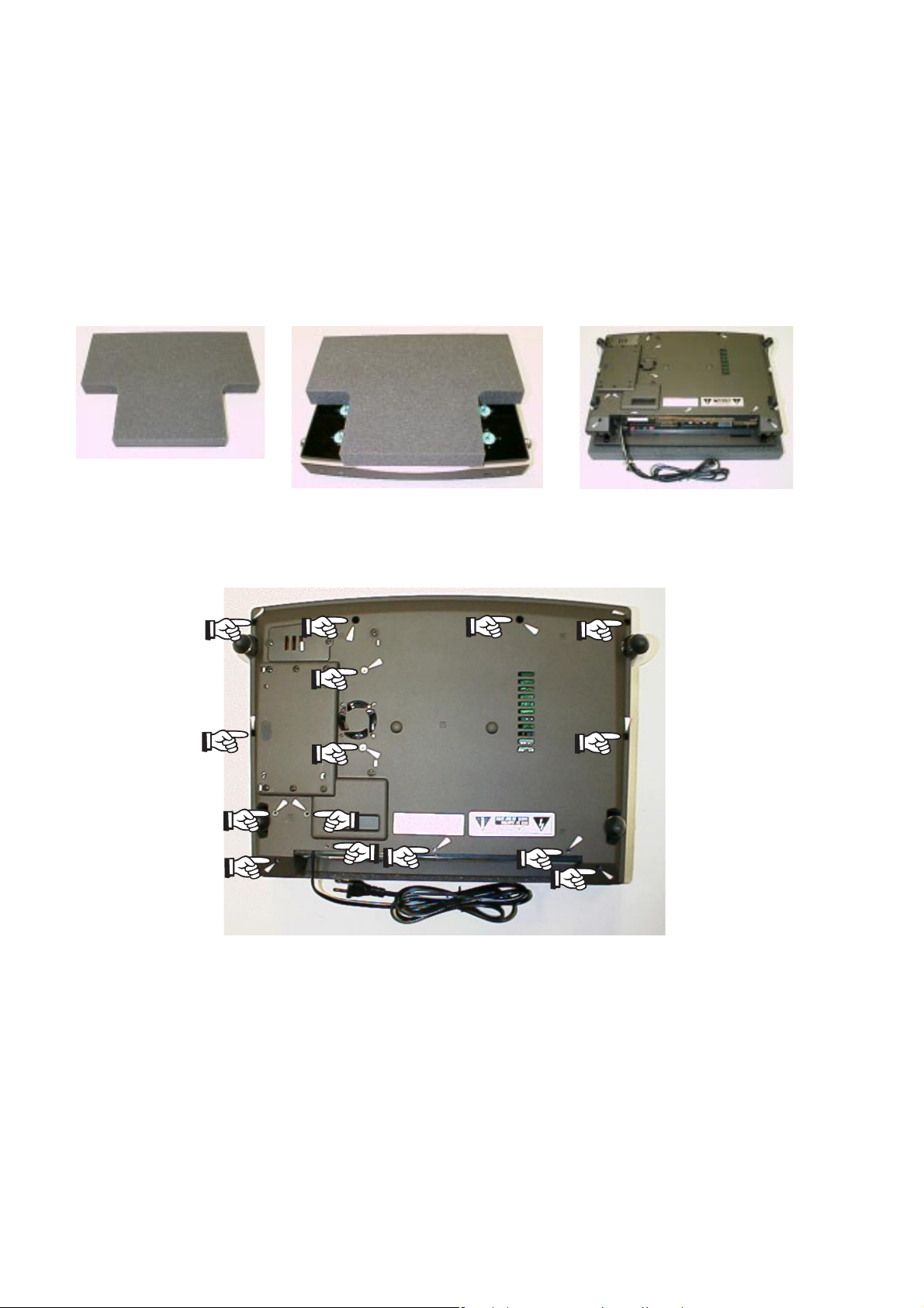
2-1. HOW TO DISASSEMBLE MR2020
1. Take the bottom case (001G) apart
(1) Tur n MR2020 upside down by the jig (Refer to fig.1-3).
Take care that the top cover will not damaged, especially
the 4 levers. If you don't have the jig, you prepare to put
some magazine or telephone guide under the MR2020
(The height is over 3cm books).
2-1
Fig.1 A jig for MR2020
(2) Remove 15 screws as shown in fig.4.
Fig.2 The jig on MR2020 Fig.3 Turning over the MR2020
Fig.4 Position of 15 screws
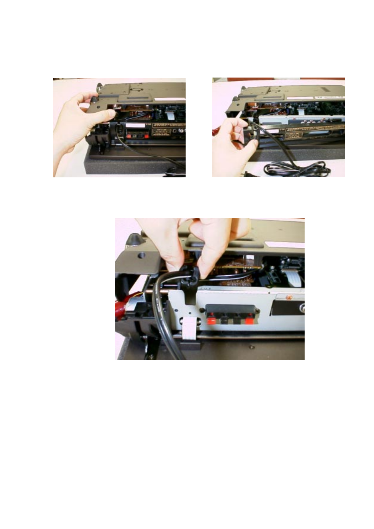
(3) While lifting the bottom case, remove the rear panel as
shown in fig.5-6.
2-2
Fig.5 Lifting the bottom case
(4) Remove the mains code bush as shown in fig.7.
Fig.6 Removing the rear panel
Fig.7 Removing the mains code bush
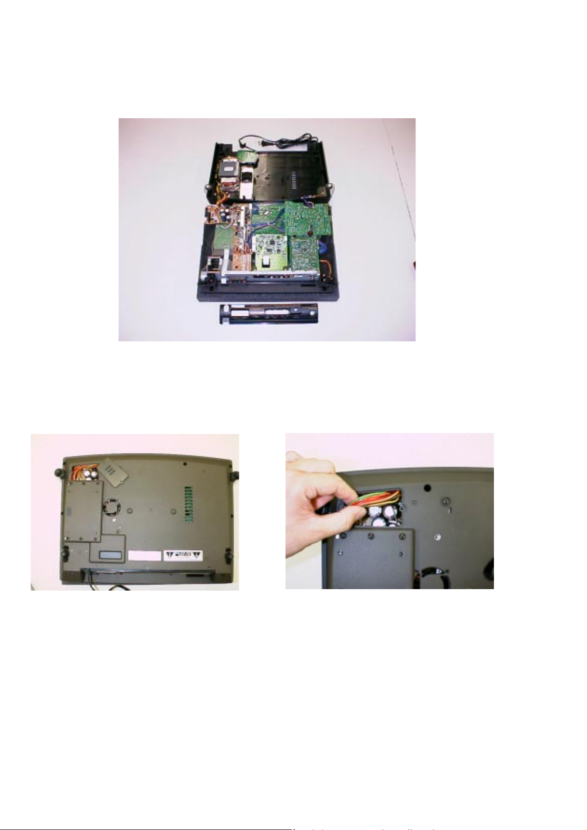
(5) Lift up the bottom case, remov e the put the one with turning
to front side (Refer to fig.8).
2-3
Fig.8 Taking the bottom case apart
Remark for reassemble
When you fit the bottom case, remove the lid of the bottom
case (Refer to fig.9) and confirm the arrangement of lead
lines for transformer.(Refer to fig.10).
Fig.9 Removing the lid of the bottom case
Fig.10 Arrangement of lead lines
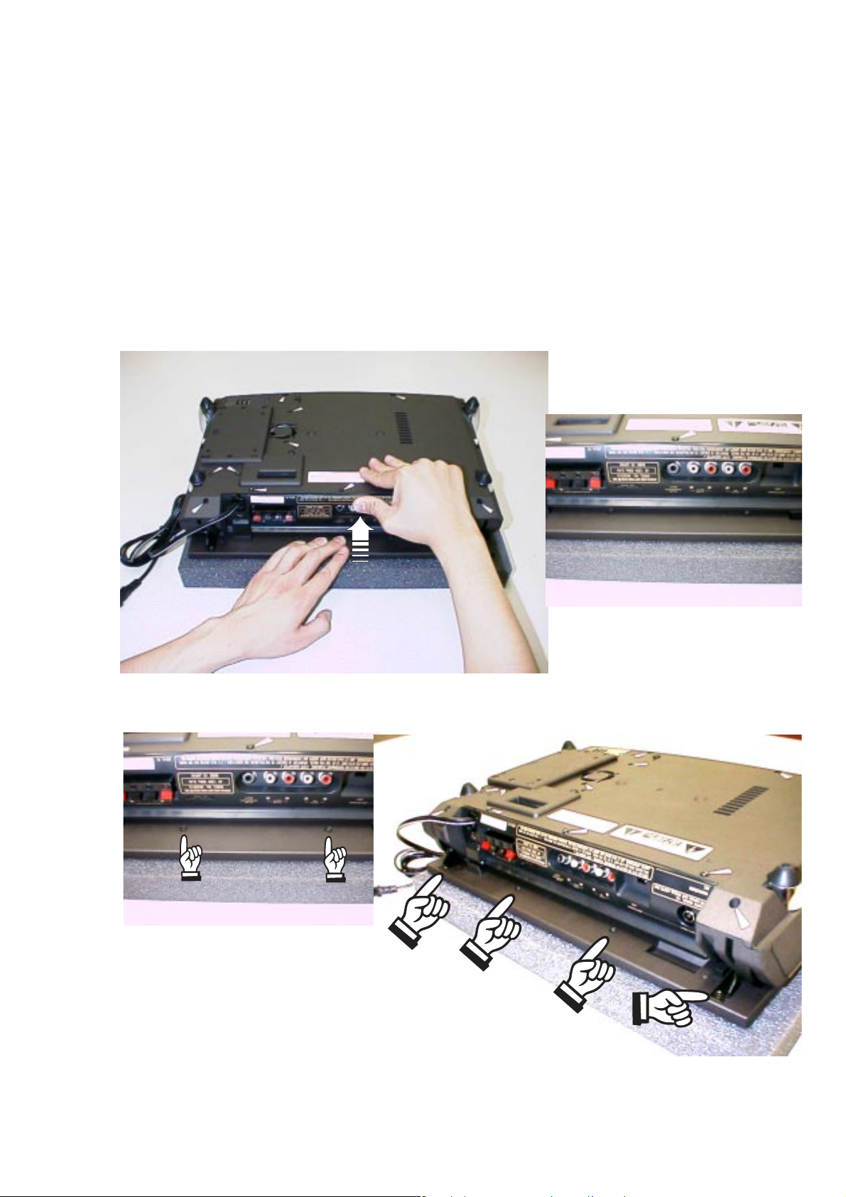
2. Take the top panel (001D) apart
(1) Turn MR2020 upside down by the jig. (Refer to fig.1-3)
Take care that the top cover will not damaged, especially
the 4 levers. If you don't have the jig, you prepare to put
some magazine or telephone guide under the MR2020.
(The height is over 3cm books)
(2) Push the rear panel while keeping hold the top cover (see
fig.11 below). The top cover will move 5mm. (fig.12-13)
Now, 4 screws on the top cover will become accessible.
(fig.14) Take out these screws. (M3 type screw)
2-4
Fig.11 Pushing the rear panel
Fig.13 Pushed the rear panel
Fig.12 Before pushing the rear panel
Fig.14 Positions of 4 screws

(3) Turn the MR2020 to its normal operating position.
(4) Open the top cover of MR2020 by hand.
(5) Take out the 2 screws (M2 type screw) on the top (see
fig.15).
2-5
Fig.15 Positions of 2 screws on the top
(6) The upper par t and lower part of the top cover are
connected to each other with adhesive tape. Separate
these parts by pushing the transparent upper part in the
middle (on CD shaped part) from the lower part, while
holding the lower part.
(7) The upper part and lower part of the top co ver were
separated (See fig.16-17).
Fig.16 The upper part of top cover (the reverse side)
Fig.17 The lower part of top cover and the others

2-2. REP AIR INTRODUCTION
PREPARATION FOR CD BLOCK
1. Set a disc for repair into product.
2. Tur n the product upside down on the jig (Parts
No.*MR2021JIG). Take care that the top cover will not
damaged, especially the 4 lever s. (Refer to "How to
disassemble MD2020")
3. For the top panel will not open while repairing, remove
the connecting wires of panel motor from the connector
(J812).
4. Repair and operate it on the upside down position of
the product.
PREPARATION FOR MAIN AMPLIFIER PCB (P704)
1. Main amplifier is BTL output.
2. For removing the main amplifier PCB (P704) from the
product, remove the wire (W802) from the terminal
(WU02) of microprocessor PCB (PU04). Connect
another wire with terminal (WU02) and GND as chassis
instead of the wire (W802).
REMARK
Remove the bottom case from the product, Do not output
signals of over 1W from both channels more than 10
minutes continuously.
2-6
2-3. EXPLANA TION OF CIRCUITS
FAN OPERATION
The voltage added to the diode (D852) is depended on
the resistance of the thermistor (R857) and resistors
(R855,R858). When the temperature of the heat sink
goes up, the resistance of the thermisor (R857)
decreases, and the voltage added to the diode (D852)
increases.
1. When the temperature of the heat sink is over 70
degrees Celsius, then D852 is on, through R852, Q851
is on, and the fan starts to revolve.
2. When the temperature of the heat sink is approx. 100
degrees Celsius or more, through R853, Q853 is on,
and the product is STAND-BY status. But, if the fan
revolve normally, the temperature of the heat sink will
not be over 100 degrees Celsius and not be STANDBY status. Therefore, the procedure of the o ver heat
protection circuit check is as follows;
(1) Connect the test point (J814) with a resistor of 680
ohm.
(2) If the product is STAND-BY status, this circuit is normal.
(3) Remove the resistor of 680 ohm from the test point
(J814).
FAN OPERATION CHECK
Keep outputting 2.5W from both channels of the product.

When the bottom case is closing. If the fan revolving starts
within 10 minutes, the function is correct working.
Otherwise keep outputting 1W from both channels of the
product when the bottom case is opening. If the f an revolving
starts within 5 minutes, the function is correct working.
REMARK
Do not output over 1W when the bottom case is open.
VCC CONTROL
The regulation of primary voltage is not so higher
intentionally for decreasing the no-load loss. Therefore, this
circuit is used for the product to keep the voltage tolerance
of the power IC. This circuit do not work when the output is
from 0 to approx. 1Vrms. Then VCC is supplied from D709
only. When the output is more than 1Vrms, through D701D704, R722, D706, and Q703 is on, current is supplied
from Q702. When the output is over approx. 3Vrms, D709
is off, and VCC is supplied from Q702 only.
SPEAKER PROTECTION
1. When either terminal of BTL outputs connect with GND
(chassis) by mistake, the speaker protection circuit will
work as follows. through R707-R710, Q704 or Q705 is
on, and Q706 is on. Then #5Pin for Q701 is 0V, power IC
(Q701) will be in power off. Therefore, the product will be
STAND-BY status.
2. When the VCC CONTROL circuit is working correctly,
maximum current of R825 is 1A, and voltage between
R825 load is maximum 0.33V. When both terminals of BTL
outputs are shorted on outputting over 0.25W, R825 is
supplied over 2A, Q807 and Q803 is on, and the product
will be STAND-BY status.
2-7
CD 5V ON/OFF CONTROL
The voltage for CD (CD 5V) is supplied from QX04 when
the following conditions are satisfied fully. (for noise and
laser protection)
1. Setting a disc on the product, and QU08 is on.
2. Closing top panel, and #78Pin for QU10 is 0V.
3. The product is in CD mode.
MUTE CONTROL
Mute signals output from microprocessor (QU10) are
"MUTE (Pin No.37)", "MUTE2 (Pin No .7)", and "DSC MUTE
(Pin No.5)".
Fig.1 is workable output terminals by each mute signals,
Fig.2 is the status of each mute.
Q701(SPK)
MUTE YES YES YES NO NO
MUTE2 NO NO
DSC MUTE NO NO NO NO YES
QN01-QN04
(PHONE)
Fig.1
QX05,QX06
(SUB WOOFER)
QX07,QX08
(LINE OUT)
YESNO
QE01
NO

2-8
Fig.2
POWER
ON/OFF
MUTE YES YES YES YES YES
MUTE2 YES YES NO YES NO
DSC MUTE NO YES NO NO NO
TOP PANEL OPEN SENSOR
1. The pulse (T=84msec, Duty 50%) is always added to LED
(QU15), from #30Pin of QU10, through RF28 and QU22.
2. Cover the sensor with your fingers, the collector voltage
of QU01 goes up over 0.7VP-P. and through RU71 and
QU09, the pulse of 5VP-P inputs to #29Pin of QU10. Then
the top panel will open.
3. Not needing to cover the sensor with your fingers, QU01
receives the light of LED reflected by lens oneself.
Therefore, the collector of QU01 adds the reverse pulse
through RF29, QU26 and RF32, for reduced incorrect
working. So, the voltage of residual pulse for the collector
of QU01 is suppressed to 0.1VP-P.
REMARK
When the sensor receives sunlight or a strong light as
incandescent, top panel might open.
CD MODE STOP OR
TRACK JUMP
MUTE BUTTON
ON
MODE
CHANGE
VOLUME
MINIMUM
POPS NOISE KILLER
RX72, CX70 and QX70 are the circuit to delay power supply
for approx. 2 seconds. Therefore, this circuit prevents pops
noise generation when power switch is on or off.
SUB WOOFER
Sub woofer output is composed a low pass filter of cut-off
frequency 150Hz octave 12dB. It is output 2V for AUX L,R
input 60Hz, 200mV (volume is maximum).
REMARK
Sub woofer output level is depended on volume control.
3 SERVICE MODE
1. How to set the service mode
(1) While holding the CLOCK and CLEAR buttons together,
put the mains plug to mains outlet.
(2) FL check mode will start.
(3) While in FL check mode, each time the FUNCTION button
pressed (within 2 seconds), the mode changes in the
following order.
TR FREQ (Tracking point frequency memory mode) ➛
CD TEST (CD test mode) ➛ FL CHK (FL check mode) ➛
TR FREQ (Tracking point frequency memory mode)
2. FL CHECK MODE
FL check mode will continue until change other mode.
3. TRACKING POINT FREQUENCY MEMORY MODE
This mode is not available for repair(This is for check in
factory.). If you set in this mode, some frequencies will
register in each preset memory.
REMARK
User programmed frequencies will be deleted.
While in Tracking point frequency memory mode, press the
MEMO button. Press the CLEAR and the DISPLAY buttons
together. The display shows “CLEAR” 2 seconds. Then all
memories will be clear.
3-1
4. CD TEST MODE
(1) Press the “+ ” button, then the sledge move to the outside.
Press the “-” button then the sledge move to the inside.
Press the CLEAR button while the sledge is moving, then
the sledge stop.
(2) Press the MEMO button, then the laser pick up unit is
giving out the beam. Press the MEMO button again then
the laser pick up unit stop beam out. All operations are
available without the Disc.
(3) While in CD test mode, CD play is available in opening
the top panel.
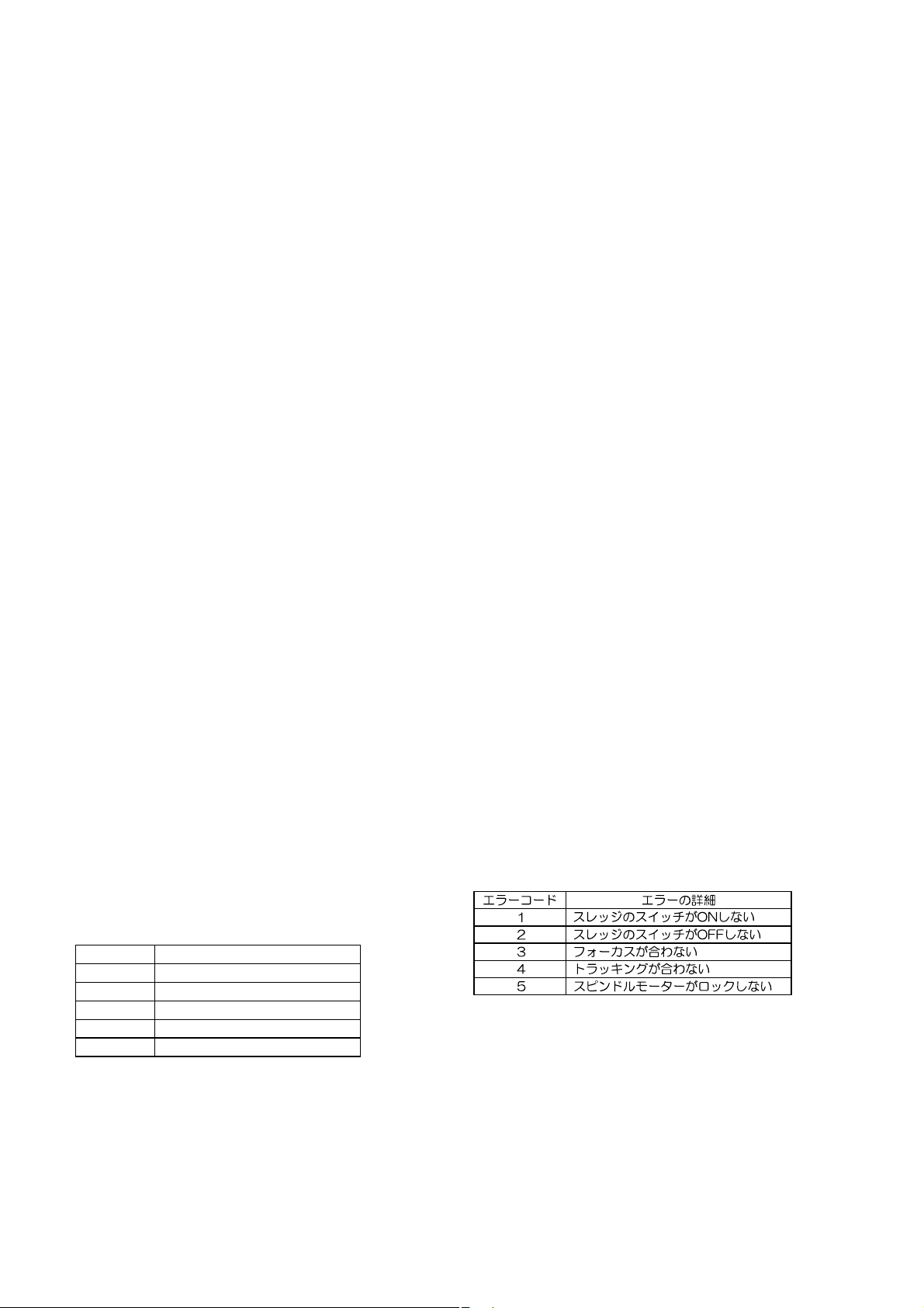
(4) If any ERROR is happened, the displa y shows “CD ERRX”.
(X is a ERROR code.) The ERROR message will not be
clear until pressing STOP or POWER buttons.
Error Code Description
1 The sledge switch not turn on.
2 The sledge switch not turn off.
3 The laser pick up unit not focus.
4 The tracking is not fixed.
5 The spindle motor not locked.
5. How to stop the service mode
Press the POWER button. Then product will be in POWER
OFF (STAND-BY).
REMARK
The microprocessor will not be clear by this operation.
(Refer to "3. TRACKING POINT FREQUENCY MEMORY
MODE")

4-1 4-1
4-1 BLOCK DIAGRAM
CD UNIT CD94V5B1
SPNDLE
MOTOR
SLED
MOTOR
D SC
SENSOR(CD)
PCK UP
FOCUS
TRACK
TDA7073AT
TDA7073AT
SUPPLY
TDA1300T
HF AMP
SERVO
DRIVER
SERVO
DRVER
CD BOARD NAMI 8
DECODER/
U-COM
SAA7372
PQ30RV2 PQ05RF2
+10V
2SA1307
+21V
U COM
PQ12RF2
+20V
U COM
+8V +5V
DAC
U COM
AM STEREO
F ONLY
7808
ANT
TUNER 95
ECO 5
RDS
/02 ONLY
ANALOG
+5V(CD)
+5V U COM)
+9 3V(POWER AMP)
+8V(CD)
+12V(PANEL MOTOR)
26V(FL)
F1(FL)
F2(FL)
4-3 MICROPROCESSOR DATA
AUX
L NE
IN
BUFFER
NJM4558
+5V
MAIN U COM
A/D INPUT
PANEL
DR VE
C
SUB
OUT
W F
DRIVER
TEMP
DETECT
POWER
AN7125
H P AMP
NJM4556
FL
AMP
S P
H P(SW)
DISPLAY
R C
PANEL
PHOTO
SENSOR
FL
RC5
M
FAN
MOTOR
BUFFER
NJM4558
I2C
PANEL
ON TOP
OPN/CLS
KEY
PRE AMP
TE6321
BOTTOM
E Q
KEY
Pin No Pin Name S gnal Name I/O Active Slow Function
1 P10 (INT0) POW DWN INT L POWER DOWN
2 P11 (INT1) STANDBY OUT L L POWER STANDBY
3 P12 (INT2) SDA N/OUT I C SDA(for RDS DSC)
4 P13 (DVO) SCL OUT H L I C SCL(for RDS DSC)
5 P14 DSC MUTE OUT L L DSC MUTE
6 P15 CD STANDBY OUT L L CD STANDBY
7 P16 MUTE2 OUT L L L NE MUTE
8P17 * N NC
9 TEST N GND
10 P21 (XTIN) 32 768kHz IN SUB X TAL
11 P22 (XTOUT) 32 768kHz OUT SUB X TAL
12 RESET RESET N L RESET
13 XIN 8 0MHz IN X TAL
14 XOUT 8 0MHz OUT X TAL
15 VSS GND GND
16 P20 (INT5) HOLD IN L HOLD N
17 P30 (INT3) RCIN INT RC 5 BUS IN
18 P31 RCOUT OUT L L RC 5 BUS OUT
19 P32 (SCK) UNE CLK OUT H L TUNER CLK
20 P33 (SI) TUNE WE OUT L TUNER WRITE ENABLE
21 P34 (SO) UNE SDA IN/OUT H L TUNER SDA
22 P35 (HSCK) TUNER ST M ON IN H L TUNER STEREO/MONO
23 P36 CD7 RESET OU T L L CD7 RESET
24 P37 (HSO) DISC IN IN H DISC IN SENSOR
25 P00 SILD OUT L L CD7 CONTROL
26 P01 RAB OUT H L CD7 CONTROL
27 P02 SCL OUT H L CD7 CONTROL
28 P03 SDA IN/OUT H L CD7 CONTROL
29 P04 P SEN IN N H PANEL SENSOR IN
30 P05 P SEN OUT OUT H L PANEL SENSOR OUT
31 P06 P MOTOR P OUT H L PANEL MOTOR +
32 P07 P MOTOR N OUT H L PANRL MOTOR
33 VDD +5V +5VS VDD
34 P60 (G15) * IN N C
35 P61 (G14) * IN N C
36 P62 (G13) AMPON OUT H L AMP POWER ON
37 P63 (G12) MUTE OUT H L MUTE
38 P64 (G11) RDS ON OUT H L RDS POWER
39 P65 (G10) 11G OUT H DIGIT OUT
40 P66 (G9) 10G OUT H DIGIT OUT
Pin No Pin Name Signal Name I/O Active Slow Function
41 P67 (G8) 9G OUT H DIGIT OUT
42 P70 (G7) 8G OUT H DIGIT OUT
43 P71 (G6) 7G OUT H DIGIT OUT
44 P72 (G5) 6G OUT H DIGIT OUT
45 P73 (G4) 5G OUT H DIGIT OUT
46 P74 (G3) 4G OUT H DIGIT OUT
47 P75 (G2) 3G OUT H DIGIT OUT
48 P76 (G1) 2G OUT H DIGIT OUT
49 P77 (G0) 1G OUT H DIGIT OUT
50 P80 (S0) P16 OUT H SEGMENT OUT
51 P81 (S1) P15 OUT H SEGMENT OUT
52 P82 (S2) P14 OUT H SEGMENT OUT
53 P83 (S3) P13 OUT H SEGMENT OUT
54 P84 (S4) P12 OUT H SEGMENT OUT
55 P85 (S5) P11 OUT H SEGMENT OUT
56 P86 (S6) P10 OUT H SEGMENT OUT
57 P87 (S7) P9 OUT H SEGMENT OUT
58 P90 (S8) P8 OUT H SEGMENT OUT
59 P91 (S9) P7 OUT H SEGMENT OUT
60 P92 (S10) P6 OUT H SEGMENT OUT
61 P93 (S11) P5 OUT H SEGMENT OUT
62 P94 (S12) P4 OUT H SEGMENT OUT
63 P95 (S13) P3 OUT H SEGMENT OUT
64 P96 (S14) P2 OUT H SEGMENT OUT
65 P97 (S15) P1 OUT H SEGMENT OUT
66 VKK B Power Supply for FL
67 P40 (KEY0) Key0 IN H Key0
68 P41 (KEY1) Key1 IN H Key1
69 P42 (KEY2) Key2 IN H Key2
70 P43 (KEY3) Key3 IN H Key3
71 P44 (KEY4) Key4 IN H Key4
72 P45 (KEY5) Key5 IN H Key5
73 P46 (KEY6) Key6 IN H Key6
74 P47 (KEY7) Key7 IN H Key7
75 P50 (A D) DAVN N L RDS DAVAN
76 P51 (A D) PSWN N L RDS PSWN
77 P52 (A D) P OPEN N L PANEL SW OPEN
78 P53 (A D) P CLOSE N L PANEL SW CLOSE
79 P54 VER SET0 IN 0 1 0 1
80 P55 VER SET1 IN 0 0 1 1
:F
:U
:K KK
: /2
 Loading...