


DR-6000
Service
DR6000 /F1N, /K1G, /N1G
/K1B, /N1B, /U1B
Manual
STANDBY
ON/OFF
POWER
REMARK : This service manual explains them by extracting specifications
designed for the model DR6000 only. The explanation for CD-R module
"MAR770" (Loader : CDL4009' + CD-R Main board) is not mentioned on this
service manual.
The CD-R module information is described in the service manual of CD-R
modules <MAR770/MAR775>.
CD RECORDER DR6000
Recordable
ReWritable
DISPLAY SCROLL
OPEN/CLOSE
SOURCE ERASE
Compact Disc Recorder
REC TYPE REW FF
EASY JOG
CANCEL
STORE
FINALIZE
DELETE
MENU
PUSH ENTER
REC
PLAY/PAUSESTOP
LEVEL PHONES
-+
DR6000
TABLE OF CONTENTS
SECTION PAGE
MAIN UNIT
1. Servicing the DR6000 ................................................................................................................................ 1
2. TECHNICAL SPECIFICATIONS ............................................................................................................... 3
3. WARNINGS .............................................................................................................................................. 4
4. SERVICE HINTS AND TOOLS ................................................................................................................. 5
5. SIAGNOSTIC SOFTWARE ....................................................................................................................... 6
6. FAULTFINDING TREES ......................................................................................................................... 11
7. FAULTFINDING GUIDE .......................................................................................................................... 15
8. WIRING DIAGRAM ................................................................................................................................. 25
9. BLOCK DIAGRAM ................................................................................................................................... 27
10. SCHEMATIC DIAGRAM AND PARTS LOCATION ................................................................................. 29
11. EXPLODED VIEW AND PARTS LIST ..................................................................................................... 37
12. ELECTRICAL PARTS LIST ..................................................................................................................... 40
Please use this service manual with referring to the user guide ( D.F.U. ) without fail.
R
Printed in Japan
DR6000
385K855010 MIT
3120 785 22360
First Issue 2000.08

MARANTZ DESIGN AND SERVICE
MARANTZ AMERICA, INC.
WILDASH AUDIO SYSTEMS NZ
Using superior design and selected high grade components, MARANTZ company has created the ultimate in stereo sound.
Only original MARANTZ parts can insure that your MARANTZ product will continue to perform to the specifications for which
it is famous.
Parts for your
MARANTZ equipment are generally available to our National Marantz Subsidiary or Agent.
ORDERING PARTS :
Parts can be ordered either by mail or by Fax.. In both cases, the correct part number has to be specified.
The following information must be supplied to eliminate delays in processing your order :
1. Complete address
2. Complete part numbers and quantities required
3. Description of parts
4. Model number for which part is required
5. Way of shipment
6. Signature : any order form or Fax. must be signed, otherwise such part order will be considered as null and void.
USA
MARANTZ AMERICA, INC
440 MEDINAH ROAD
ROSELLE, ILLINOIS 60172
USA
PHONE : 630 - 307 - 3100
FAX : 630 - 307 - 2687
AMERICAS
SUPERSCOPE TECHNOLOGIES, INC.
MARANTZ PROFESSIONAL PRODUCTS
2640 WHITE OAK CIRCLE, SUITE A
AURORA, ILLINOIS 60504 USA
PHONE : 630 - 820 - 4800
FAX : 630 - 820 - 8103
AUSTRALIA
JAMO AUSTRALIA PTY LTD
1 EXPO COURT, P.O. BOX 350
MT. WAVERLEY VIC 3149
AUSTRALIA
PHONE : +61 - 3 - 9543 - 1522
FAX : +61 - 3 - 9543 - 3677
NEW ZEALAND
WILDASH AUDIO SYSTEMS NZ
14 MALVERN ROAD MT ALBERT
AUCKLAND NEW ZEALAND
PHONE : +64 - 9 - 8451958
FAX : +64 - 9 - 8463554
EUROPE / TRADING
MARANTZ EUROPE B.V.
P.O.BOX 80002, BUILDING SFF2
5600 JB EINDHOVEN
THE NETHERLANDS
PHONE : +31 - 40 - 2732241
FAX : +31 - 40 - 2735578
AUSTRALIA
TECHNICAL AUDIO GROUP PTY, LTD
558 DARLING STREET,
BALMAIN, NSW 2041,
AUSTRALIA
PHONE : 61 - 2 - 9810 - 5300
FAX : 61 - 2 - 9810 - 5355
THAILAND
MRZ STANDARD CO.,LTD
746 - 754 MAHACHAI ROAD.,
WANGBURAPAPIROM, PHRANAKORN,
BANGKOK, 10200 THAILAND
PHONE : +66 - 2 - 222 9181
FAX : +66 - 2 - 224 6795
TAIWAN
PAI- YUING CO., LTD.
6 TH FL NO, 148 SUNG KIANG ROAD,
TAIPEI, 10429, TAIWAN R.O.C.
PHONE : +886 - 2 - 25221304
FAX : +886 - 2 - 25630415
BRAZIL
PHILIP DA AMAZONIA IND. ELET. ITDA
CENTRO DE INFORMACOES AO
CEP 04698-970
SAO PAULO, SP, BRAZIL
PHONE : 0800 - 123123
FAX : +55 11 534. 8988
(Discagem Direta Gratuita)
CANADA
LENBROOK INDUSTRIES LIMITED
633 GRANITE COURT,
PICKERING, ONTARIO L1W 3K1
CANADA
PHONE : 905 - 831 - 6333
FAX : 905 - 831 - 6936
SINGAPORE
WO KEE HONG (S) PTE LTD
WO KEE HONG CENTRE
NO.23, LORONG 8, TOA PAYOH
SINGAPORE 319257
PHONE : +65 2544555
FAX : +65 2502213
MALAYSIA
WO KEE HONG ELECTRONICS SDN. BHD.
SUITE 8.1, LEVEL 8, MENARA GENESIS,
NO. 33, JALAN SULTAN ISMAIL,
50250 KUALA LUMPUR, MALAYSIA
PHONE : +60 3 - 2457677
FAX : +60 3 - 2458180
JAPAN
Technical
MARANTZ JAPAN, INC.
35- 1, 7- CHOME, SAGAMIONO
SAGAMIHARA - SHI, KANAGAWA
JAPAN 228-8505
PHONE : +81 42 748 1013
FAX : +81 42 741 9190
KOREA
MK ENTERPRISES LTD.
ROOM 604/605, ELECTRO-OFFICETEL, 16-58,
3GA, HANGANG-RO, YONGSAN-KU, SEOUL
KOREA
PHONE : +822 - 3232 - 155
FAX : +822 - 3232 - 154
SHOCK, FIRE HAZARD SERVICE TEST :
CAUTION : After servicing this appliance and prior to returning to customer, measure the resistance between either primary AC
cord connector pins ( with unit NOT connected to AC mains and its Power switch ON ), and the face or Front Panel of product and
controls and chassis bottom.
Any resistance measurement less than 1 Megohms should cause unit to be repaired or corrected before AC power is applied, and
verified before it is return to the user/customer.
Ref. UL Standard No. 1492.
In case of difficulties, do not hesitate to contact the Technical
Department at above mentioned address.
991207MIT
1.Servicing the DR6000
1.1 INTRODUCTION:
The DR6000 is the consumer version of a CD recorder, this means that the SCMS (Serial Copy Management System) is
included. The DR6000 can only record on the Audio CDRs (Consumer Use).
The DR6000 is suitable for recording and playback of CD-RW discs (CD-Re Writable disc).
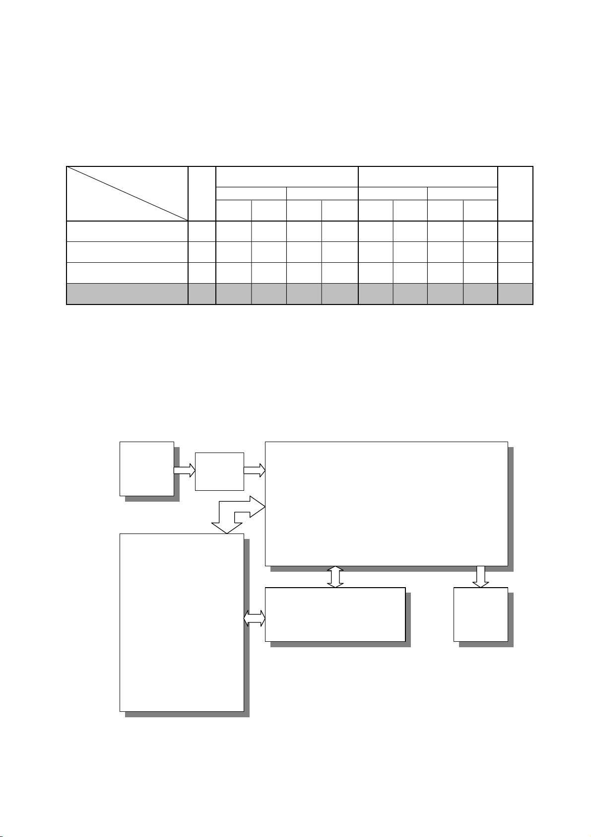
Playback & Recording and Disc
Disc
Player/Recorder
Audio CD Player
Current products Ex:CD-17
Audio CD Player
CD-RW playback Ex:CD-17MK II
CD-RW Recorder
For Professional Ex:CDR630/640
CD-RW Recorder
For Consumer Ex:DR6000
CDR
CD
Consumer Disc
Finalized
non
Finalized
Professional Disc
Finalized Finalized
non
Finalized
Consumer Disc
Finalized
PP no P no no no no no -
PP no P no P no P no -
P P P/R P P/R P/R P/R P/R P/R no
P P P/R P no P/R P/R no no YES
CD-RW
non
Finalized
Professional Disc
non
Finalized
SCMS
Consumer : For Digital Audio
Professional : For General use (Including PC)
P : Playback
R : Recording
1.2 OPENING THE PRODUCT :
The product can be opened by removing the top cover (6 screws). Once the product is opened one can have access to the
several PCB's and the main module. To have access to the Display PCB, the Headphone PCB first the front cover has to
be removed (See dismantling instructions on page1-7).
POWER
SW
BOARD
Trans-
former
POWER SUPPPLY
and
AUDIO
BOARD
MOTER
BOARD
CDR LOADER
DISPLAY BOARD
Below the several PCB's and it function and service policy will be discussed:
1
HEAD
PHONE
BOARD

1.2.1 CDR loader (CDR main module CDL4009 or MAR770):
This complete CDR loader is considered as not repairable in the field. therefore this module will be repaired centrally. A
module exchange procedure will be set up for this purpose. The module can be removed from the product by removing 4
screws and the transformer (see demounting the CDR module on page 1-7), and loosing the connectors.
This module is the complete CD recorder, it contains the following parts:
CD Mechanism (CDM4009'). Underneath this mechanism a PCB is mounted which is adjusted to the mechanism (laser
current settings are stored in EEPROM).
Loader Assy. This mechanical assy takes care for the tray control.
Main PCB. This PCB takes care that the (analog or digital) signal to be recorded is converted into a suitable signal which
can be recorded on the disc.
Digital signals with an other sampling frequency then 44.1kHz will be converted in the sample rate converter (DASP) to
44.1kHz.
Analog signals will be first converted into a digital converter by the AD converter.
This PCB also takes care that the signal from the CD (playback) is converted into a suitable digital signal (or analog via
the DA converter).
The main microprocessor controls the several functions of this PCB.
1.2.2 Power SW Board.
This PCB contains the Power SW, which is jointed the Power bottom on the front panel. All parts are available as spare
parts.
1.2.3 Power Supply and Audio Board.
This PCB consists of power supply part and audio part. The power suppluy part delivers the several voltages for the diffrent
PCB in the DR6000. On this power supply sevel fuses (secondary side) are mounted on this PCB. The audio part takes care
that the signal from CDR main module is converted into an analog signal via DA converter and outputs the analog signal.
This PCB contains the output and input connectors also. All parts are available as spare parts.
1.2.4 Display Board.
This PCB contains the Display, which informs the user about the status of the recording/playback process and it also takes
care for scanning the keys on the front panel. The information from the keys is fed via a I C connection to the main
microprocessor on the CDR loader module. Information which needs to be displayed is also fed via this I C line from the
main microprocessor on the CDR loader module to the display controller.
The parts for this PCB are available as service parts so this PCB can be repairable up to component level.
2
2
1.2.5 Headphone Board.
This PCB contains the headphone socket and potentiometer which controls the headphone volume. All parts are available
as spare parts.
IMPORTANT
In case of replace the CD-R module "MAR770", the initialization is necessary.
Please initialize the CD-R module with following orders.
1. Press the POWER button (POWER ON) while depressing FINALIZE button and REC
TYPE button together.
2. FL Display shows;
WAIT
PGM PROTOCOL
PGM PORT END
3. Press the POWER button (POWER OFF).
Then the CD-R module set up to DR6000 own status.
2

2 TECHNICAL SPECIFICATIONS
GENERAL
System .................................................................................................... Compact disc digital audio
Number of channels ................................................................................ 2 (stereo)
Applicable discs ...................................................................................... CD, CD-R (digital audio), CD-RW (digital audio)
Power Requirement
F version ........................................................................................... AC 100 V 50 / 60 Hz
K version ........................................................................................... AC 110 V / 220 V 50 /60 Hz
N version ........................................................................................... AC 230 V 50 Hz
U version. .......................................................................................... AC 120 V 60 Hz
Power Consumption ................................................................................ 24 W
Operating Temperature . ......................................................................... 5 °C - 35 °C
Dimension (MAX)
Width ................................................................................................. 440 mm
Height ................................................................................................ 87 mm
Depth ................................................................................................ 317 mm
Weight ................................................................................................ 4.6 kg
AUDIO
Frequency Response ............................................................................. 20 Hz - 20 kHz
Playback S/N .......................................................................................... 105 dB
Playback Dynamic Range ....................................................................... 96 dB
Playback Total Harmonic Distortion ........................................................ 90 dB
Recording S/N (analog) .......................................................................... 90 dB
Recording Dynamic Range (analog) ....................................................... 92 dB
Recording Total Harmonic Distortion (analog) ........................................ 84 dB
Analog Output Voltage ............................................................................. 2 Vrms
Digital Coaxial Output ............................................................................. 0.5 V (p-p) / 75 ohms
Digital Optical Output .............................................................................. - 20 dB
Headphones ............................................................................................ 0 - 5 Vrms / 8 - 2000 ohms
Recording values for line input
Digital Coaxial Input (automatic sample rate conversion) ....................... 32 - 48 kHz
Digital Optical Input (automatic sample rate conversion) ........................ 32 - 48 kHz
Analog Input ............................................................................................ 560 mVrms / 50 kohms
Specifications subject to change without prior notice.
3
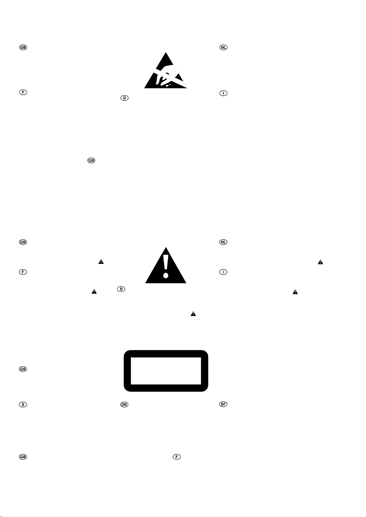
3. WARNINGS
WARNING
All ICs and many other semiconductors are susceptible to
electrostatic discharges (ESD). Careless handling during
repair can reduce life drastically.
When repairing, make sure that you are connected with the
same potential as the mass of the set via a wristband with
resistance. Keep components and tools at this potential.
ATTENTION
Tous les IC et beaucoup d´autres semi-conducteurs sont
sensibles aux décharges statiques (ESD). Leur longévite
pourrait être considérablement écourtée par le fait qu´aucune
précaution nést prise à leur manipulation.
Lors de réparations, s´assurer de bien être relié au même
potentiel que la masse de l´appareil et enfileer le bracelet
serti d´une résistance de sécurité.
Veiller à ce que les composants ainsi que les outils que l´on
utilise soient également à ce potentiel.
WARNUNG
Alle ICs und viele andere Halbleiter sind empfindlich
gegenüber elektrostatischen Entladungen (ESD).
Unsorgfältige Behandlung im Reparaturfall kann die
Lebensdauer drastisch reduzieren.
Sorgen Sie dafür, daß sie im Reparaturfall über ein Pulsarmband mit Widerstand mit dem Massepotential des
Gerätes verbunden sind.
Halten Sie Bauteile und Hilfsmittel ebenfalls auf diesem
Potential.
AVAILABLE ESD PROTECTION EQUIPMENT :
anti-static table mat large 1200x650x1.25mm 4822 466 10953
anti-static wristband 4822 395 10223
connection box (3 press stud connections, 1M ) 4822 320 11307
extendible cable (2m, 2M , to connect wristband to connection box) 4822 320 11305
connecting cable (3m, 2M , to connect table mat to connection box) 4822 320 11306
earth cable (1M , to connect any product to mat or to connection box) 4822 320 11308
KIT ESD3 (combining all 6 prior products - small table mat) 4822 310 10671
wristband tester 4822 344 13999
ESD
WAARSCHUWING
Alle IC´s en vele andere halfgeleiders zijn gevoelig voor
electrostatische ontladingen (ESD).
Onzorgvuldig behandelen tijdens reparatie kan de levensduur
drastisch doen vermindern. Zorg ervoor dat u tijdens reparatie
via een polsband met weerstand verbonden bent met hetzelfde
potentiaal als de massa van het apparaat.
Houd componenten en hulpmiddelen ook op ditzelfde potentiaal.
AVVERTIMENTO
Tutti IC e parecchi semi-conduttori sono sensibili alle scariche
statiche (ESD).
La loro longevità potrebbe essere fortemente ridatta in caso di
non osservazione della più grande cauzione alla loro
manipolazione. Durante le riparationi occorre quindi essere
collegato allo stesso potenziale che quello della massa
delápparecchio tramite un braccialetto a resistenza.
Assicurarsi che i componenti e anche gli utensili con quali si
lavora siano anche a questo potenziale.
small 600x650x1.25mm 4822 466 10958
Safety regulations require that the set be restored to its
original condition and that parts which are identical with
those specified be used.
Safety components are marked by the symbol
Les normes de sécurité exigent que l`appareil soit remis
à l`état d`origine et que soient utilisées les pièces de
rechange identiques à celles spécifiées.
Les composants de sécurité sont marqués
DANGER: Invisible laser radiation when open.
AVOID DIRECT EXPOSURE TO BEAM.
Varning !
Advarsel !
Osynlig laserstrålning när apparaten är öppnad och
spärren är urkopplad. Betrakta ej strålen.
Bei jeder Reparatur sind die geltenden Sicherheitsvorschriften zu beachten. Der Originalzustand des Gerätes
darf nicht verändert werden. Für Reparaturen sind Originalersatzteile zu verwenden.
Sicherheitsbauteile sind durch das Symbol markiert.
LASER PRODUCT
Usynlig laserstråling ved åbning når sikkerhedsafbrydere
er ude af funktion. Undgå udsaettelse for stråling.
SAFETY
Veiligheidsbepalingen vereisen, dat het apparaat in zijn
oorspronkeliijke toestand wordt teruggebracht en dat
onderdelen, identiek aan de gespecificeerde, worden toegepast.
De Veiligheidsonderdelen zijn aangeduid met het symbool
Le norme di sicurezza estigono che l´apparecchio venga
rimesso nelle condizioni originali e che siano utilizzati i
pezzi di ricambiago identici a quelli specificati.
Componenty di sicurezza sono marcati con
CLASS 1
Varoitus !
Avatussa laitteessa ja suojalukituksen ohitettaessa olet alttiina
näkymättömälle laserisäteilylle. Älä katso säteeseen !
After servicing and before returning the set to customer
perform a leakage current measurement test from all
exposed metal parts to earth ground, to assure no
shock hazard exists.
The leakage current must not exceed 0.5mA.
"Pour votre sécurite, ces documents doivent être utilisés par
des spécialistes agréés, seuls habilités à réparer votre
appareil en panne".
4
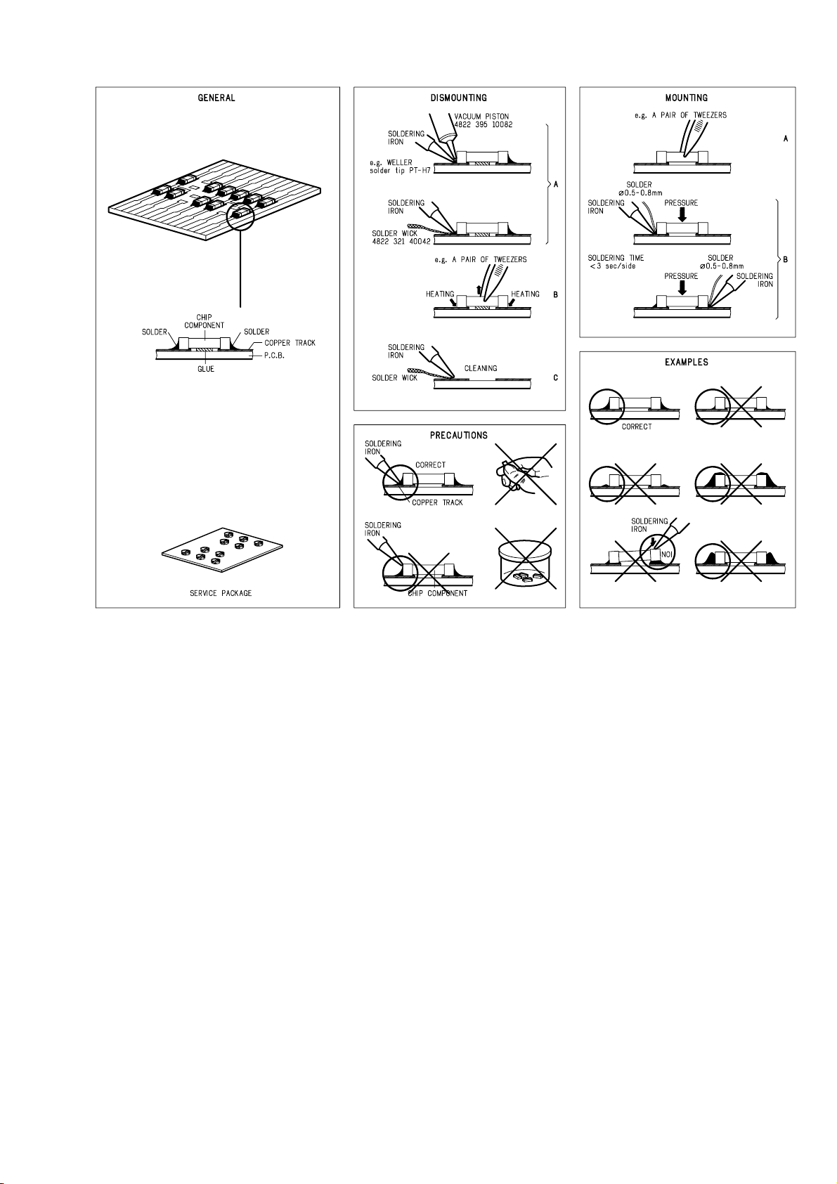
4. SERVICE HINTS AND TOOLS
SERVICE TOOLS
Audio signals disc 4822 397 30184
Disc without errors (SBC444)+
Disc with DO errors, black spots and fingerprints (SBC444A) 4822 397 30245
Disc (65 min 1kHz) without no pause 4822 397 30155
Max. diameter disc (58.0 mm) 4822 397 60141
Torx screwdrivers
Set (straight) 4822 395 50145
Set (square) 4822 395 50132
13th order filter 4822 395 30204
Hexagon socket screw button (No. 1.5)
5
5. Diagnostic Software
5.1 Dealer mode
The purpose of the dealer mode is to prevent people taking out
the CD inside the player at exhibitions, showrooms etc.. This
mode disables the open/close function of the player.
The dealer mode can be switched on and off pressing keys
[OPEN/CLOSE] and [STOP] of the CDR player simultaneously
while switching on the unit. The dealer mode is stored in the
flash memory and can only be changed by executing the above
actions.
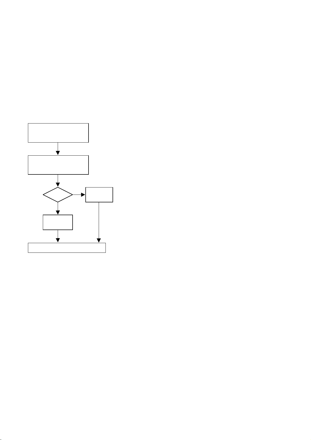
5.2 Dealer diagnostics
Press <REWIND> + <FFWD>
simultaneously and switch
ON unit
Display blinks
“BUSY”
during test
NO
Set OK?
YES
Set displays
“
PASSED
To end test, switch OFF unit
”
Figure 5-1
Set displays
“ERROR”
5.2.1 Description
The intention of the dealer diagnostics is to give an indication
of the CDR player status. An inexperienced, even non-technical
dealer will/can perform the test. Tests are executed
automatically without need for external tools or disassembly of
the unit. This test checks the CDR main board using the same
tests as the electrical service diagnostics program. Only the
result of the test, "PASSED" or "ERROR", will be shown on the
display. Pressing keys [F FWD] and [REWIND] simultaneously
while switching on the unit, starts the test. Switching off the unit
ends the test.
5.2.2 Requirements to perform the test
• Working keyboard to start up the test.
• Working local display to check the output messages.
6
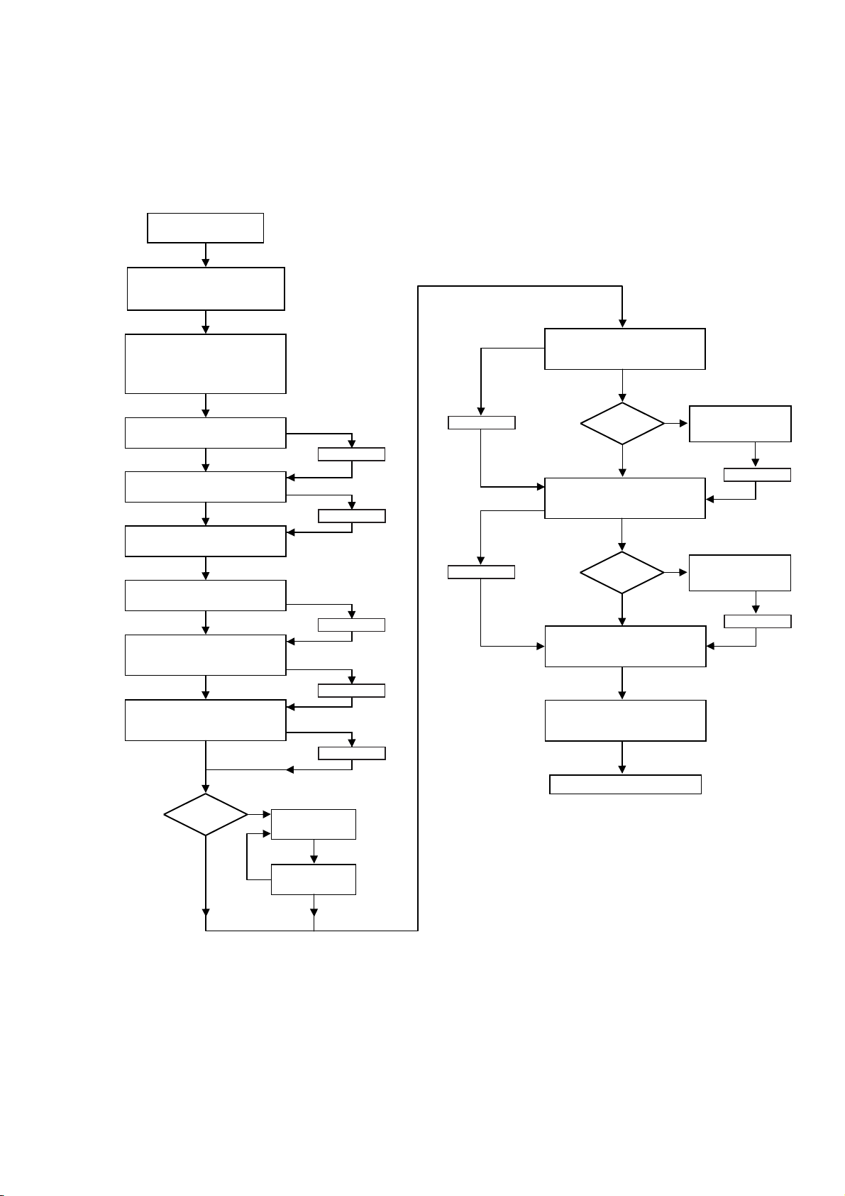
5.3 Electrical service diagnostics
ELECTRICAL SERVICE DIAGNOSTICS
(software versions, test for defective components)
If power ON,
switch power OFF
Load CD-DA disc (SBC444A)
Press <PLAY> + <F FWD>
simultaneously and switch ON unit
PLAYER
INFORMATION
Display :
"PLAYER ID"
"SW VERSION BACK END"
"SW VERSION CDR LOADER"
(DR6050
CDR MAIN
BOARD TEST
Display :
PASS OR FAIL
Display :
PASS OR FAIL
Display :
PASS OR FAIL
Display :
PASS OR FAIL
Display :
PASS OR FAIL
Display :
PASS OR FAIL
"SW VERSION CD LOADER"
"DTST1"
DRAM test (7702)
"DTST2"
FLASH CHECKSUM test (7702)
"DTST3"
FLASH ERASE test (7702)
"DTST4" *
CODEC test (7702)
"DTST5"
CDR LOADER
COMMUNICATION test
"DTST5"
*
CD LOADER
COMMUNICATION test
* FOR DR6050 ONLY
)
ABORT TEST
Press <F FWD>
ABORT TEST
Press <F FWD>
ABORT TEST
Press <F FWD>
ABORT TEST
Press <F FWD>
ABORT TEST
Press <F FWD>
ABORT TEST
Press <F FWD>
ABORT TEST
Press <F FWD>
LOADER TESTS
CDR LOADER TEST
CD-DA disc must be loaded
Display shows current disc time
Test OK?
YES
CD LOADER TEST *
CD-DA disc must be loaded
Display shows current disc time
Test OK?
YES
DISPLAY TEST
DISPLAY TEST
Display segments blink at f=1Hz
KEYBOARD &
RC TEST
KEYBOARD & RC TEST
Display shows name of pressed keys
Press <F FWD>
NO
Display :
or
or
* FOR DR6050 ONLY
NO
Display :
or
or
"BERR1"
"NO CDDA"
"NO DISC"
Press <F FWD>
"BERR2"
"NO CDDA"
"NO DISC"
Press <F FWD>
Tests OK?
YES
NO
Display :
"DERRn"
n = failed test
Display next
failed test
To end test, switch OFF unit
Figure 5-2
7

5.3.1 Description
The intention of the electrical service diagnostics is to show the
software versions present in the player and to direct the dealer
towards defective internal units. The units are : the CDR main
board, the CDR loader, the CD loader in case of a DR6050 and
the keyboard/display board. A sequence of tests is executed
automatically. Some of the tests can be aborted or skipped
without the result being taken into account. External tools or
disassembly of the unit is not necessary to get the diagnostic
information. Pressing keys [PLAY/PAUSE] and [F FWD]
simultaneously while switching on the unit, starts the test.
Switching off the unit ends the test.
Loader tests
These tests determine if the CDR loader and the CD loader in
case of a DR6050 work correctly. A CD-DA disc with a
minimum of 3 tracks needs to be inserted in both loaders. A
disc test is executed to check focus control, disc motor control,
radial control and jump grooves control. The disc test is
performed by audio play-back of 5 seconds at the beginning,
middle and end of the disc.
CDR loader test
During the test, the current disc time is shown. In case of an
error the message "BERR1" will be displayed and the [F FWD]
key must be pressed to continue with the following test.
Pressing the [F FWD] key also aborts this test.
5.3.2 Requirements to perform the test
• Working keyboard to start up the test.
• Working local display to check the output messages.
• A CD-DA disc with a minimum of 3 tracks in all trays to
perform the disc test.
5.3.3 Description of the tests
Player information
In this part of the test the following important information can be
checked without removing the cover :
• Recorder ID.
• SW-version back end of player.
• SW-version CDR loader.
• SW-version CD loader (only for DR6050).
CDR main board test
As soon as the CDR main board tests are finished, all failure
messages (if any) will be displayed sequentially by pressing the
[F FWD] key. The message "DERRn" will be displayed with n
indicating the faulty test number.
If one of the tests is aborted with the [F FWD] key, no error
message will be displayed for this test. The flash data erase
test ("DTST3") can not be aborted !
The CDR main board test consists out of :
DRAM test
Display : "DTST1". The DRAM used for buffer management is
tested by writing, reading and verifying test patterns.
CD loader test
For CDR775 only. During the test, the current disc time is
shown. In case of an error the message "BERR2" will be
displayed and the [F FWD] key must be pressed to continue
with the following test. Pressing the [F FWD] key also aborts
this test.
Display test
All segments will blink at a frequency of 1 Hz. Pressing the [F
FWD] key will start the next test because the user has to check
for himself if all segments work properly.
Keyboard and remote control tests
The test will give the user the ability to test every key without
executing the function assigned to it. Therefore, the user needs
to press every key on the keyboard and the remote control. The
display will show the name of the key being pressed. Pressing
more than one key at once will give an unpredictable result
except for the service combinations : [PLAY/PAUSE] + [STOP],
[PLAY/PAUSE] + [F FWD], [F FWD] + [REWIND], [ERASE] +
[RECORD], [PLAY/PAUSE] + [RECORD].
Flash checksum test
Display : "DTST2". This test checks the checksum of the
player's SW stored in the flash.
Flash data erase
Display : "DTST3". During this test, all temporary information
(CDtxt) in the flash is erased.
CODEC (ADC/DAC) test
Display : "DTST4". This test checks the CODEC IC by writing,
reading and verifying test patterns. The test is not applicable for
CDR950.
CDR communication test
Display : "DTST5". The communication between the host
processor (DASP) and the CDR loader via the DSA-R-bus is
tested.
CD communication test
Display : "DTST6"). The communication between the host
processor (DASP) and the CD loader is tested. The test is only
applicable for DR6050.
8
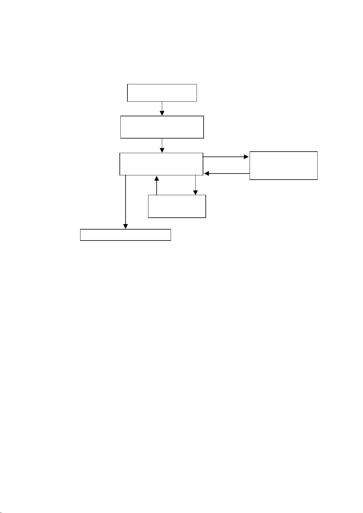
5.4 Mechanical service diagnostics
MECHANICAL SERVICE DIAGNOSTICS
(test for defective components)
If power ON,
switch power OFF
Press <PLAY/PAUSE> + <STOP>
simultaneously and switch
To end test, switch OFF unit
ON unit
FOCUS TEST
Display shows
Visual inspection
SLEDGE TEST
Visual inspection
Display shows
“BUSY”
“BUSY”
<
OPEN
>
<
CLOSE
>
<FWD><REWIND>
TRAY TEST
Visual inspection
Display shows
even if tray is blocked
“OPENED”
5.4.1 Description
No external tools are required to perform this test. The cover
needs to be removed because the user has to check the
movements of the tray, focus and sledge visually. Pressing
keys [PLAY/PAUSE] and [STOP] simultaneously while
switching on the unit, starts the test. Switching off the unit ends
the test. In case of a DR6050, one can check the CD loader
mechanics in the same way by pressing the above key
combination on the CD player keys.
5.4.2 Requirements to perform the test
• Working keyboard to cycle through the tests and to start up
the test.
• Working local display to check the output messages.
5.4.3 Description of the tests
Focus control test
The focussing lens is continuously moving up and down. The
display reads "BUSY".
Sledge control test
After pressing [F FWD] the sledge continuously moves up and
down. Pressing [REWIND] stops the sledge at the position it is
in and the focus control test resumes. The display reads
"BUSY".
Figure 5-3
pressing [F FWD]. One has to stop these tests pressing
[REWIND] before it is possible to close the tray again.
Depending on the action the display reads "OPEN",
"OPENED", "CLOSE" or "BUSY".
Tray control test
This test starts from within the focus control test routine.
Pressing [OPEN/CLOSE] moves the tray in or out. In the tray
open position one can initiate focus and sledge tests by
9
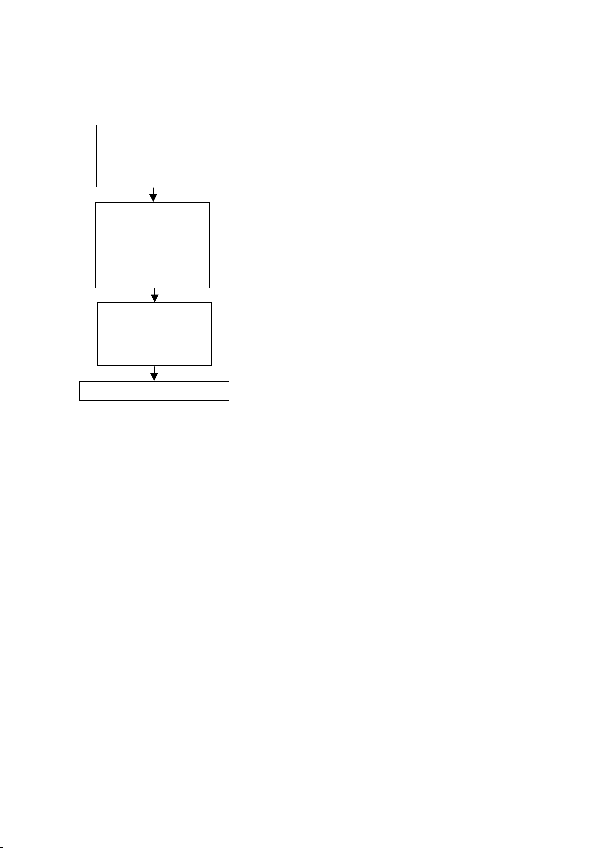
5.5 DC-erase service mode
DC ERASE SERVICE MODE
(erasement of complete CD-RW)
Load CD-RW disc
<ERASE> + <RECORD>
simultaneously and switch
Display shows:
“
ER mm:ss
Press
ON unit
”
mm
ss :remaining seconds
TOTAL
illuminated
To end test, switch OFF unit
:remaining minutes
and
REM
are also
Display shows:
“
when the erase function is
PASSED
completed
ERROR
“
if DC ERASE fails
Figure 5-4
”
”
5.5.1 Description
This test is initiated by pressing [ERASE] and [RECORD]
simultaneously while switching on the unit. The player will
erase a complete CD-RW disc (including PMA and ATIP lead
out area) at speed N=2. The display shows the countdown of
the remaining time required for the operation to complete. The
format is "ER mm:ss", where "mm" are the remaining minutes
and "ss" the remaining seconds. After completion the message
"PASSED" is shown, and the player has to be switched off and
on again to start up in normal operating mode. Switching off the
unit before completion of the test, leaves the disc in an
unpredictable state. In such case only a complete DC-erase
procedure can recover the CD-RW disc.
5.5.2 Requirements to perform the test
• Functional CDR player.
• A CD-RW audio disc must be present in the tray.
10
 Loading...