


DV-18
Service
DV18 /F1N, /K1G, /S1G, /U1G, /U1B
Manual
SECTION PAGE
1. MAIN UNIT
1.1 TECHNICAL SPECIFICATIONS ......................................................................................................... 1-1
1.2 REGIONAL CODES ............................................................................................................................ 1-2
1.3 INFORMATIONS ................................................................................................................................. 1-3
1.4 SERVICING HINT ............................................................................................................................... 1-4
1.5 DISASSEMBLY ................................................................................................................................... 1-5
1.6 REPLACEMENT OF PRINCIPAL COMPONENTS ............................................................................. 1-6
1.7 SERVICE MODE ................................................................................................................................. 1-8
1.8 ELECTRICAL ADJUSTMENT ........................................................................................................... 1-10
1.9 WAVEFORM ..................................................................................................................................... 1-12
1.10 WIRING DIAGRAM ........................................................................................................................... 1-13
1.11 BLOCK DIAGRAM ............................................................................................................................. 1-15
1.12 SCHEMATIC DIAGRAM .................................................................................................................... 1-17
1.13 PARTS LOCATION ........................................................................................................................... 1-27
1.14 EXPLODED VIEW AND PARTS LIST ............................................................................................... 1-30
1.15 ELECTRICAL PARTS LIST ............................................................................................................... 1-33
DVD Player
DVD PLAYER DV-18
SURROUND
CHAPTER
VIDEO
POWER
TITLE
STANDBY
SHUFFLE
DIMMER
OPEN/CLOSE
TIME
FTS
PBC
TRACK
TRACK
TOTAL
SCAN
DIGITAL OUT
PLAY
TRACK
TITLE
CHAPTER
SCAN
SVCD
SHUFFLE
REPEAT
A-B
TABLE OF CONTENTS
PAUSE
STOP
MAX
MIN
PHONES
LEVEL
2. TKM1000MZ ( DVD MODULE for MARANTZ )
2.1 SCHEMATIC DIAGRAM AND PARTS LOCATION ............................................................................. 2-1
2.2 MICROPROCESSOR AND IC DATA ................................................................................................ 2-15
2.3 EXPLODED VIEW AND PARTS LIST ............................................................................................... 2-28
2.4 ELECTRICAL PARTS LIST ............................................................................................................... 2-30
Printed in Japan
Please use this service manual with referring to the user guide ( D.F.U. ) without fail.
DV-18
R
DV-18
370K855010 MIT
First Issue 2000.09
MARANTZ DESIGN AND SERVICE
MARANTZ AMERICA, INC.
WILDASH AUDIO SYSTEMS NZ
Using superior design and selected high grade components, MARANTZ company has created the ultimate in stereo sound.
Only original MARANTZ parts can insure that your MARANTZ product will continue to perform to the specifications for which
it is famous.
Parts for your
MARANTZ equipment are generally available to our National Marantz Subsidiary or Agent.
ORDERING PARTS :
Parts can be ordered either by mail or by Fax.. In both cases, the correct part number has to be specified.
The following information must be supplied to eliminate delays in processing your order :
1. Complete address
2. Complete part numbers and quantities required
3. Description of parts
4. Model number for which part is required
5. Way of shipment
6. Signature : any order form or Fax. must be signed, otherwise such part order will be considered as null and void.
USA
MARANTZ AMERICA, INC
440 MEDINAH ROAD
ROSELLE, ILLINOIS 60172
USA
PHONE : 630 - 307 - 3100
FAX : 630 - 307 - 2687
AMERICAS
SUPERSCOPE TECHNOLOGIES, INC.
MARANTZ PROFESSIONAL PRODUCTS
2640 WHITE OAK CIRCLE, SUITE A
AURORA, ILLINOIS 60504 USA
PHONE : 630 - 820 - 4800
FAX : 630 - 820 - 8103
AUSTRALIA
JAMO AUSTRALIA PTY LTD
1 EXPO COURT, P.O. BOX 350
MT. WAVERLEY VIC 3149
AUSTRALIA
PHONE : +61 - 3 - 9543 - 1522
FAX : +61 - 3 - 9543 - 3677
NEW ZEALAND
WILDASH AUDIO SYSTEMS NZ
14 MALVERN ROAD MT ALBERT
AUCKLAND NEW ZEALAND
PHONE : +64 - 9 - 8451958
FAX : +64 - 9 - 8463554
EUROPE / TRADING
MARANTZ EUROPE B.V.
P.O.BOX 80002, BUILDING SFF2
5600 JB EINDHOVEN
THE NETHERLANDS
PHONE : +31 - 40 - 2732241
FAX : +31 - 40 - 2735578
AUSTRALIA
TECHNICAL AUDIO GROUP PTY, LTD
558 DARLING STREET,
BALMAIN, NSW 2041,
AUSTRALIA
PHONE : 61 - 2 - 9810 - 5300
FAX : 61 - 2 - 9810 - 5355
THAILAND
MRZ STANDARD CO.,LTD
746 - 754 MAHACHAI ROAD.,
WANGBURAPAPIROM, PHRANAKORN,
BANGKOK, 10200 THAILAND
PHONE : +66 - 2 - 222 9181
FAX : +66 - 2 - 224 6795
TAIWAN
PAI- YUING CO., LTD.
6 TH FL NO, 148 SUNG KIANG ROAD,
TAIPEI, 10429, TAIWAN R.O.C.
PHONE : +886 - 2 - 25221304
FAX : +886 - 2 - 25630415
BRAZIL
PHILIP DA AMAZONIA IND. ELET. ITDA
CENTRO DE INFORMACOES AO
CEP 04698-970
SAO PAULO, SP, BRAZIL
PHONE : 0800 - 123123
FAX : +55 11 534. 8988
(Discagem Direta Gratuita)
CANADA
LENBROOK INDUSTRIES LIMITED
633 GRANITE COURT,
PICKERING, ONTARIO L1W 3K1
CANADA
PHONE : 905 - 831 - 6333
FAX : 905 - 831 - 6936
SINGAPORE
WO KEE HONG (S) PTE LTD
WO KEE HONG CENTRE
NO.23, LORONG 8, TOA PAYOH
SINGAPORE 319257
PHONE : +65 2544555
FAX : +65 2502213
MALAYSIA
WO KEE HONG ELECTRONICS SDN. BHD.
SUITE 8.1, LEVEL 8, MENARA GENESIS,
NO. 33, JALAN SULTAN ISMAIL,
50250 KUALA LUMPUR, MALAYSIA
PHONE : +60 3 - 2457677
FAX : +60 3 - 2458180
JAPAN
Technical
MARANTZ JAPAN, INC.
35- 1, 7- CHOME, SAGAMIONO
SAGAMIHARA - SHI, KANAGAWA
JAPAN 228-8505
PHONE : +81 42 748 1013
FAX : +81 42 741 9190
KOREA
MK ENTERPRISES LTD.
ROOM 604/605, ELECTRO-OFFICETEL, 16-58,
3GA, HANGANG-RO, YONGSAN-KU, SEOUL
KOREA
PHONE : +822 - 3232 - 155
FAX : +822 - 3232 - 154
SHOCK, FIRE HAZARD SERVICE TEST :
CAUTION : After servicing this appliance and prior to returning to customer, measure the resistance between either primary AC
cord connector pins ( with unit NOT connected to AC mains and its Power switch ON ), and the face or Front Panel of product and
controls and chassis bottom.
Any resistance measurement less than 1 Megohms should cause unit to be repaired or corrected before AC power is applied, and
verified before it is return to the user/customer.
Ref. UL Standard No. 1492.
In case of difficulties, do not hesitate to contact the Technical
Department at above mentioned address.
991207MIT

1. TECHNICAL SPECIFICATIONS
Discs played
DVD video disc ............................................... 12 cm single sided, single layer
Compact disc
(CD-DA, Video CD) ......................................... 12 cm, 8 cm
Video system .................................................... PAL (625/50) / NTSC (525/60)
Audio system ................................................... Linear PCM audio
Video output
Line output level .............................................. 1.0 Vp-p / 75 ohms, unbalanced
S1-output level ................................................. Y output: 1.0 Vp-p / 75 ohms unbalanced
Color different output level ............................... Y output: 1.0 Vp-p / 75 ohms unbalanced
12 cm single sided, double layer
12 cm double sided, single layer
12 cm double sided, double layer (one layer per side)
8 cm single sided, single layer
8 cm single sided, double layer
8 cm double sided, single layer
8 cm double sided, double layer (one layer per side)
MPEG 1/2 audio
Dolby Digital (AC-3)
DTS audio (Digital output only)
RCA pin Jack x 2
C output: 0.3 Vp-p / 75 ohms (PAL)
0.286 Vp-p / 75 ohms (NTSC)
4 pin mini DIN x 1
CB, CR output: 0.7 Vp-p / 75 ohms
RCA pin Jack x 3
Audio output
Line output ....................................................... 2.0 Vrms / 330 ohms
RCA pin Jack x 2 system
Digital audio output
Optical output ................................................... Optical connector x 1
Coaxial output .................................................. 0.5 Vp-p / 75 ohm RCA pin Jack x 1
DVD Iinear audio characteristics
Frequency response ........................................ 4 Hz-22 kHz (Fs = 48 kHz)
S/N ratio ........................................................... More than 110 dB (Fs = 48 kHz / 24 bit PCM)
Dynamic range ................................................. More than 100 dB (Fs = 48 kHz / 24 bit PCM)
Total harmonic distortion ................................. Less than 0.0025% (Fs = 48 kHz / 24 bit PCM)
4 Hz-44 kHz (Fs = 96 kHz)
CD audio characteristics:
Frequency response ........................................ 4 Hz - 20 kHz (EIAJ)
S/N ratio ........................................................... More than 110 dB (EIAJ)
Dynamic range ................................................. More than 100 dB (EIAJ)
Total harmonic distortion ................................. Less than 0.0025% (EIAJ)
Pickup ............................................................... Wavelength: 655 nm (DVD)
Wavelength: 790 nm (CD)
Power requirements ........................................ 120V AC, 60 Hz (/U1)
100V AC, 50 / 60 Hz (/F1)
220V AC, 50 Hz (/K1)
220 - 230V AC, 50 / 60 Hz (/S1)
Power consumption ........................................ 22 W (standby mode = approx 5 W, power off = 0 W)
Operation temperature .................................... 5 °C - 35 °C
Operation humidity range ............................... 5% - 90% (no condensation)
Dimensions ....................................................... 458 (W) x 88 (H) x 313 (D) mm (excluding protrusions)
Weight ............................................................... 6.4 kg
Supplied accessories
Auido / Video cable ......................................... x 1
D-BUS remote cable ........................................ x 1
Remote control unit .......................................... x 1
Batteries ........................................................... x 3
• For improvement purposes, specifications and design are subject to change without notice
1-1
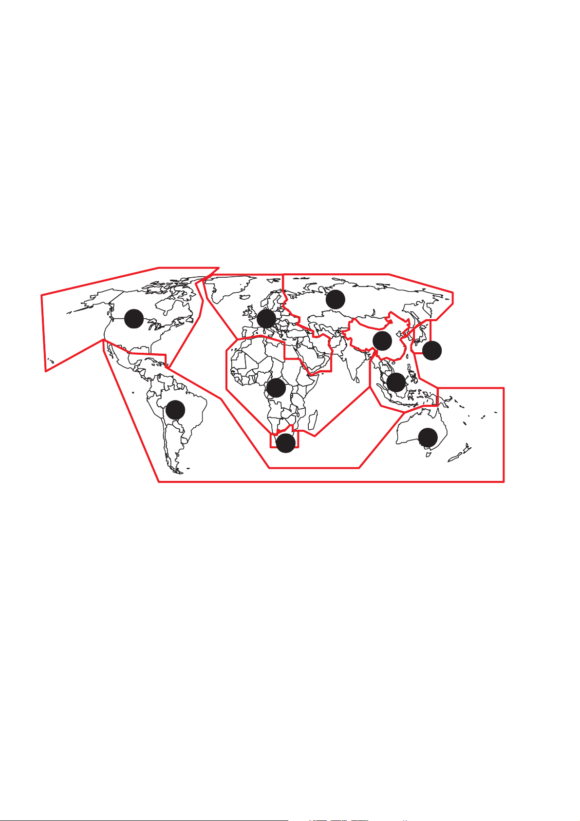
2. REGIONAL CODES
What are "regional codes"?
Motion picture studios want to control the home release of movies in different countries because theater releases arenít
simultaneous (a movie may come out on DVD in the US when itís just hitting screens in Europe). Therefore they have
required that the DVD standard include codes which can be used to lock out the playback of certain discs in certain geographical regions. Players sold in each region will have that regionís code built into the player. The player will refuse to play
these "region coded" discs which are not allowed in the region. However, regional codes are entirely optional. Discs without
codes will play on any player in any country. Some studios have already announced that only their new releases will have
regional codes. There are six regions:
1. United States and Canada
2. Europe and Japan
3. Far East (except Japan & China)
4. South America and Oceania
5. Africa and the Middle East
6. China (except Hong Kong)
5
1 2
6
2
5
3
4
2
Map of DVD Regions
4
1-2
3. INFORMATIONS
Title 1 Title 2
Chapter3Chapter1Chapter2Chapter
3
Chapter1Chapter
2
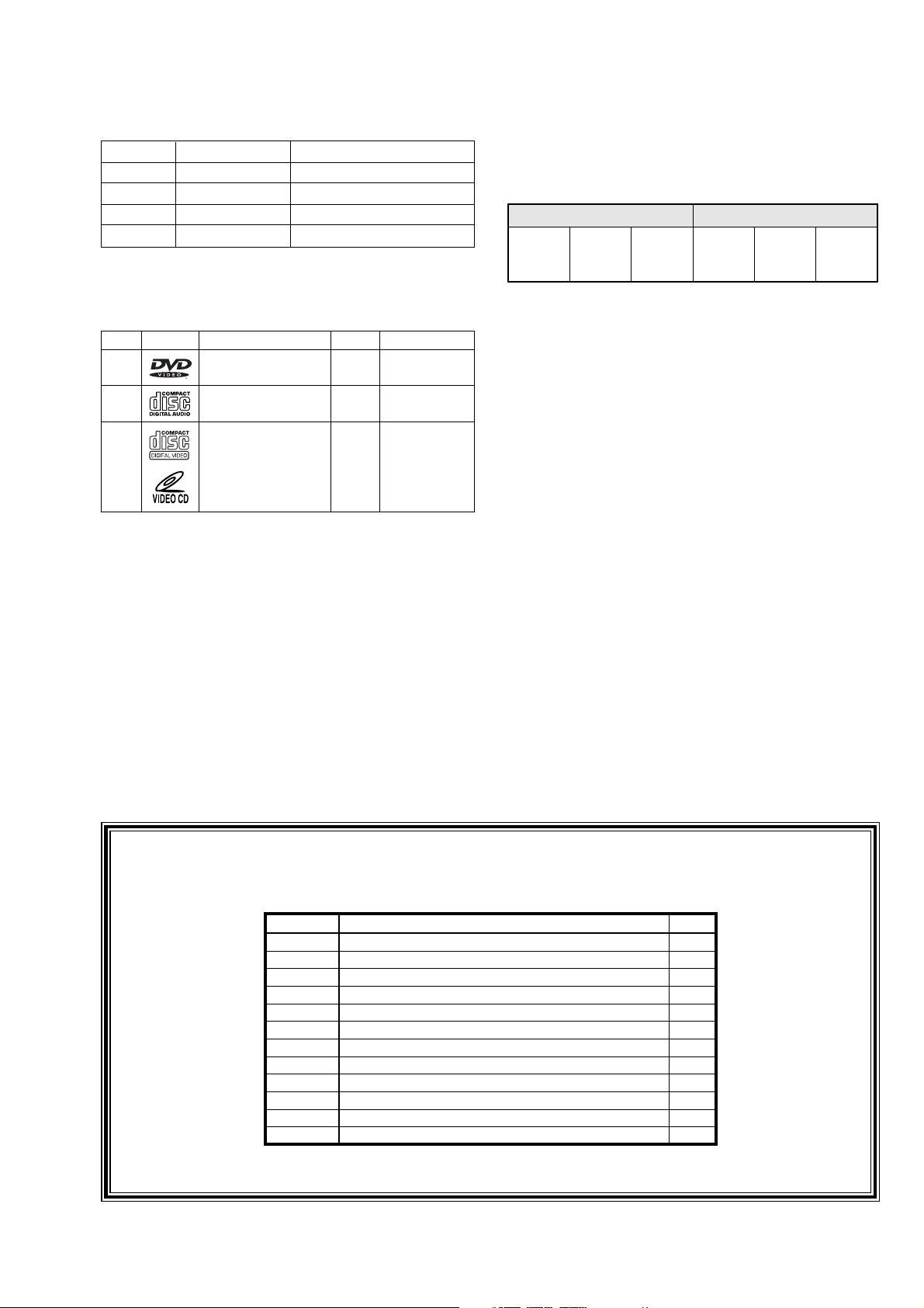
REGION CODE
VERSION REGION CODE COUNTRY
/FXX 2 JAPAN
/KXX 6 CHINA
/SXX 3 SINGAPORE/HONGKONG
/UXX 1 USA/CANADA
THE DISCS THAT THE DV-18 CAN HANDLE
The following discs can be played back with a DV-18.
disc mark playback capability size side
DVD Audio/Video
CD Audio
VCD Audio/Video single
12 cm
8 cm
12 cm
8 cm
12 cm
8 cm
single/double
single
Chapter:
A title may also be separated into chapters.
For example, a movie (title) may be separated into 3 scenes
(chapters).
Subtitles:
DVDs are recorded with up to 32 different subtitle languages.
If a disc has more than one subtitle language, you can select
the subtitle language that you want to read.
Soundtrack language:
DVDs are recorded with up to 8 different soundtrack languages.
If a disc has more than one language, you can select the
soundtrack language that you want to listen to.
Note: The regional code of the discs must meet to the regional
code of the DV-18.
DVD INFORMATION
Below is a glossary of the new terms related to DVD.
Title:
A disc may have more than one story/movie on it, so each
story/movie is called a
For example, if there are 2 movies on the disc, they are
separated into Title 1 and Title 2.
"title".
Error Code Table
Code Disc
16 D/V/C
17 D/V/C
18 D/V/C
19 D/V/C
20 V/C
32 D/V/C
33 D/V/C
34 D/V/C
35 D/V/C
36 D/V/C
37 D/V/C
38 D/V/C
Access to CD-DSP(IC490) is not available.
Sledge motor is not working.
No tracking ON.
No focus ON.
Sub code of CD,VCD is not readable.
No access to the servo DSC (IC300).
No access with the DEM/ECC (IC500).
No access with A/V decoder (IC700).
No access with the flash ROM (IC602).
No access with the EEPROM (IC603).
No access with the A/V Encoder (IC850).
No access with the Read channel (IC200).
Error Description
Multi-angles:
On some DVDs, scenes have been filmed from different angles
(up to a maximum of 9). On these discs, you can select the
angle that you want to watch. Please refer to the DVD's manual
to see which scenes have multi-angles.
Cancelling password for parental press the DIMMER button
and hold for 10 seconds while the player is stopped.
D:DVD, V:VideoCD, C:CD
1-3

4. SERVICING HINT
SERVICE HINTS
SERVICE TOOLS
Audio signals disc 4822 397 30184
Disc without errors (SBC444)+
Disc with DO errors, black spots and fingerprints (SBC444A) 4822 397 30245
Disc (65 min 1kHz) without no pause 4822 397 30155
Max. diameter disc (58.0 mm) 4822 397 60141
Torx screwdrivers
Set (straight) 4822 395 50145
Set (square) 4822 395 50132
13th order filter 4822 395 30204
DVD test disc (PAL) 4822 397 10131
DVD test disc (NTSC) ALMEDIO TDV-540
1-4
5. DISAS SEMBLY
5.DISASSEMBLY5.DISASSEMBLY
5.DISASSEMBLY
5.DISASSEMBLY5.DISASSEMBLY
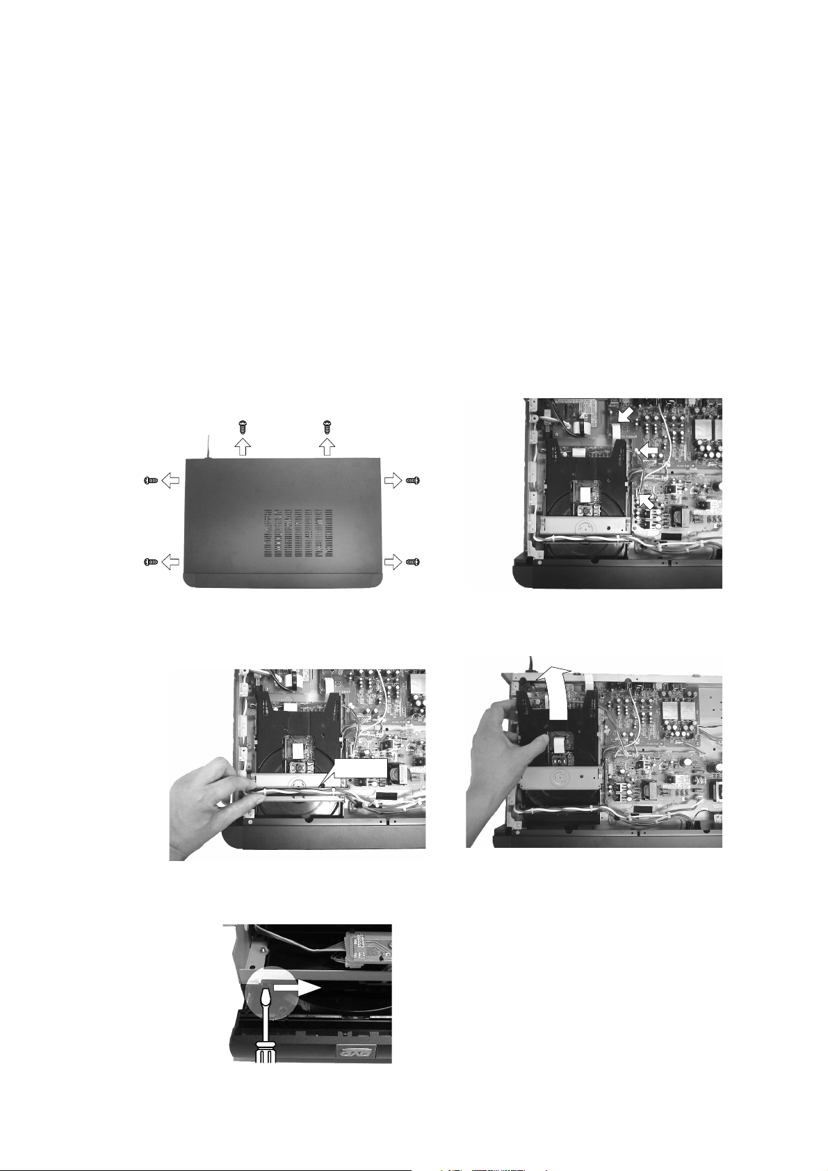
1. Remove 6 screws and remove the top cover. (see Fig.5-
1)
2. Lose the cable holder. Remove the housing of the wire
harness at the connector JP06 on the PCB PP01. (see
Fig.5-2)
3. Remove FFC and wire harness from the DVD main PCB
which mounted under the DVD mechanism. (see Fig.5-2)
4. Remove the retainer (035G) on the DVD mechanism.
(see Fig.5-3)
5. Remove 4 screws and remove DVD mechanism module.
(see Fig.5-4)
How to open the Disk tray
Put a small screwdriver into the slide knob and slide it.
Then the tray comes out. After the first centimeter it is
possible to pull the tray out by hand. (see Fig.5-5)
1. ネジを6本外し、トップカバーを外します。(Fig.5‑1)
2. ケーブルホルダーを緩め、DVD メイン基板<‑>PP01間の
ケーブルをコネクタJP06側で外します。(Fig.5‑2)
3. DVDメイン基板に接続されているFFCとケーブルを外しま
す。(Fig.5‑2)
4. DVDメカの上部のケーブルホルダー(035G)を外します。
(Fig.5‑3)
5. ネジを4 本外しDVDモジュールを取り外します。(Fig.5‑4)
ディスクトレーの開け方ディスクトレーの開け方
ディスクトレーの開け方
ディスクトレーの開け方ディスクトレーの開け方
DVD モジュールを裏返し、細いドライバーでスライドノブを
左側に押します。トレーが手前に出てきます。(Fig.5‑5)
Fig. 5-1
Fig. 5-2
035G
Fig. 5-3 Fig. 5-4
Fig. 5-5
1-5

6. REPLACEMENT OF PRINCIPAL COMPONENTS
6-1. Removal of the TRAVERSE MECHA.
6-1-1. Removal of the MECHANISM BLOCK
1) Turn the unit
eject the DISC TRAY.
2) Disconnect the power cord and remove the DISC CLAMPER
BLOCK.
3) Completely remove the DISC TRAY by pulling it outwards
while pulling up both of the stopper tabs alternately.
's power on and press the "EJECT" button to
6-1-2. Removal of the TRAVERSE MECHA.
1) Remove the four b screws on the MAIN PCB and then
disconnect the P800 connector on the MAIN PCB.
B SCREW
Fig. 6-3
2) Short the laser diode protection circuit on the PICK UP
BLOCKÕs flexible cable with solder as shown.
STOPPER TUB
Fig. 6-1
4) Disconnect the two flat cables from the P803 connectors
and one flat cable from the P808 connector on the MAIN
PCB.
5) Disconnect the P807 connector on the MAIN PCB.
6) Remove the four a retaining screws and remove the
MECHANISM BLOCK from the chassis.
P200
Fig. 6-4
Caution
To protect the laser diode from damage caused by high voltage
static electricity, a laser diode protection circuit has to be
shorted before disconnecting the flexible cable (P200 connector
on the MECHANISM PCB). It is recommended that you put
solder on the top of the soldering iron as shown in Fig. 3-5
then short the circuit at once. When you replace the TRAVERSE
MECHA., be sure to connect the P200 connector before
removing the solder at the shorted parts.
Fig. 6-2
A SCREW
SOLDER
Fig. 6-5
1-6
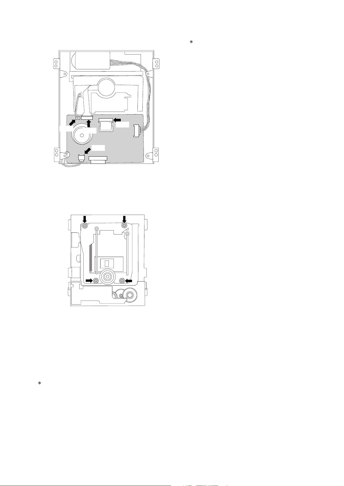
3) Carefully disconnect the two connectors (P500, P600) and
the two flat cables (P200, P300) on the MECHANISM PCB.
6-3. Replacement of the PICK UP BLOCK
Replacement of the PICK UP BLOCK itself is not
recommended because its azimuth adjustment is very
critical and requires a special jig. If PICK UP BLOCK
replacement is necessary, replace with an entire
TRAVERSE MECHANISM only.
P600
P300
P500
P200
Fig. 6-6
4) Using tweezers, release the four retaining HOOKs of the
TRAVERSE MECHA. from the rubber insulators being
careful not to damage the rubber insulators.
Fig. 6-7
5) Remove the TRAVERSE MECHA. from the MECHANISM
BLOCK.
6) Reassemble in the reverse order for installation. Never
remove the solder on the flexible cable before connecting
the P200 connector on the MECHANISM PCB.
6-2. Replacement of the SPINDLE MOTOR
Because the SPINDLE MOTOR position is very critical, jitter
adjustment should be performed after replacement.
1) Disconnect the P300 connector on the MECHANISM PCB.
2) Insert a Philips type screw driver into the hole on the TURN
TABLE of the SPINDLE MOTOR and remove the two
screws.
1-7

7. SERVICE MODE
FLD, LED TEST
1. Press the mains switch (POWER BUTTON) while
depressing the PAUSE button and STOP button.
2. Status will be on the TEST mode 1 and FL display shows
<TEST 1>.
3. Press the NEXT button, then Standby LED will be light
ON and FLD shows <LED 1>.
4. Press the NEXT button again, then Surround LED will be
light ON and FLD shows <LED 2>.
5. Press the NEXT button again, then all segments of FLD
will be light ON.
6. Press the NEXT button again, then each segments of
FLD will be light ON by press by press. (17 forms)
7. Finally FLD shows <KEY 0 0 0 0>, it will be in
“BUTTON (KEY) TEST MODE”.
8. If press some button on the front panel, FLD shows a
code of that pressed button.
9. If press the PAUSE button and STOP button
simultaneously while FLD shows <KEY 0 0 0 0>. The
status will be in “REMOTE CONTROL TEST MODE” and
FLD shows <RC6 000000>.
10.If press some button on the remote controller, FLD shows
a code of that pressed button.
11.Press the NEXT button again, then the version number of
the main microprocessor (IC600 on the DVD main PCB)
will be shown on the FLD.
12.Press the NEXT button again, then the version number of
the slave microprocessor (QF01 on the front PCB) will be
shown on the FLD.
13.Press the NEXT button again, then the status will be #2.
<TEST 1> mode. In case of finish the <TEST 1> mode,
press the mains switch (POWER BUTTON).
How to EEPROM all clear
1. Press the mains switch (POWER BUTTON) while
depressing the PLAY button and STOP button.
2. Status will be on the TEST mode 2 and FL display shows
<TEST 2>. After a couple of seconds FL display shows
<TEST2 OK>.
3. Press the PLAY button, PAUSE button and STOP button
simultaneously.
4. FL display shows <TEST OK>, then power off the mains
switch (POWER BUTTON). EEPROM should cleared.
FLD,LEDFLD,LED
FLD,LED
FLD,LEDFLD,LED
1.
2.
3.
4. 更に
5. 更に
6. 続けて
7. 最後にFLディスプレイに[
8. 各ボタンを押すと、それらに対応したコードが FLディスプ
9. FLディスプレイが[
10.RemoteControlの各ボタンを押すと、それに対応したコー
11.更に
12.更に
13.更に
EEPROMEEPROM
EEPROM
EEPROMEEPROM
1.
2.
3.
4. ディスプレイに[
の確認のしかたの確認のしかた
の確認のしかた
の確認のしかたの確認のしかた
PAUSEPAUSE
PAUSEボタンと
PAUSEPAUSE
イッチを押して下さい。
テストモ−ドテストモ−ド
テストモ−ド
テストモ−ドテストモ−ド
されます。
NEXTNEXT
NEXTボタンを押すと
NEXTNEXT
イには[
NEXTNEXT
NEXTボタンを押すと
NEXTNEXT
スプレイには[
NEXTNEXT
NEXTボタンを押すとFLディスプレイの全てのセグメ
NEXTNEXT
ントが点灯します。
NEXTNEXT
NEXTボタンを押していくとFLディスプレイの各セ
NEXTNEXT
グメントが点灯し、パターンが変わっていきます(全17種
類)。
ボタン(KEY)操作確認モードになります。
レイに表示されます。
とSTOPボタンを同時に押すと、FLディスプレイに[
000000000000
000000]と表示がされ、リモコンコードの確認画面になりま
000000000000
す。
ドがFLディスプレイ表示されます。
NEXTNEXT
NEXTボタンを押すと、メインマイコン(IC600:DVDメイ
NEXTNEXT
ン基板内)のバージョンが表示されます。
NEXTNEXT
NEXTボタンを押すと、フロント(スレーブ)マイコン
NEXTNEXT
QF01QF01
(
QF01)のバージョンが表示されます。
QF01QF01
NEXTNEXT
NEXTボタンを押すと、2.の状態に戻ります。テスト
NEXTNEXT
モード 1を終了するには電源ボタンを押して電源をOFFに
して下さい。
のクリアのしかたのクリアのしかた
のクリアのしかた
のクリアのしかたのクリアのしかた
PLAYPLAY
PLAYボタンと
PLAYPLAY
チを押して下さい。
テストモ−ドテストモ−ド
テストモ−ド
テストモ−ドテストモ−ド
され、数秒後[
PLAYPLAY
PLAYボタンと
PLAYPLAY
す。
を押して電源をOFFにしてください。
ます。
STOPSTOP
STOPボタンを同じに押しながら、電源ス
STOPSTOP
11
1に入り、ディスプレイには[
11
StandbyLEDStandbyLED
StandbyLEDが点灯し、FLディスプレ
StandbyLEDStandbyLED
LED1LED1
LED1]と表示されます。
LED1LED1
SurroundLEDSurroundLED
SurroundLEDが点灯し、FLディ
SurroundLEDSurroundLED
LED2LED2
LED2]と表示されます。
LED2LED2
KEY0000KEY0000
KEY0000]と表示され、
KEY0000KEY0000
KEY0000KEY0000
KEY0000]のときに PAUSE ボタン
KEY0000KEY0000
STOPSTOP
STOPボタンを同じに押しながら、電源スイッ
STOPSTOP
22
2に入り、ディスプレイには[
22
TESTOKTESTOK
TESTOK]と表示されます。
TESTOKTESTOK
PAUSEPAUSE
PAUSE ボタンと
PAUSEPAUSE
TEST2OKTEST2OK
TEST2OK]と表示されたら、電源スイッチ
TEST2OKTEST2OK
STOPSTOP
STOPボタンを同時に押しま
STOPSTOP
TEST1TEST1
TEST1]と表示
TEST1TEST1
EEPROMEEPROM
EEPROM がクリアされ
EEPROMEEPROM
RC6RC6
RC6
RC6RC6
TEST2TEST2
TEST2]と表示
TEST2TEST2
1-8
Type version confirmation
製品仕向の確認のしかた製品仕向の確認のしかた
製品仕向の確認のしかた
製品仕向の確認のしかた製品仕向の確認のしかた
1. Power ON the DVD player. The FL display must be
shown <NO DISC>.
2. Pressing the
button and button simultaneously.
3. FL display shows product versions as follows.
DISPLAY VERSIONS
[ USA ]
[ ]
EUROPE
[ HK S ‘PORE ]
[ CHINA ]
[ J APAN ]
.
[ NO REGION ]
/U1B, /U1G
/N1B, /N1G
/S1G
/K1B, /K1G
/F1B, /F1N
Incorrect setup.
4. Release buttons. Then FL display shows <NO DISC>
and status will be in usual mode.
Type Version setup
1. Press the mains switch (POWER BUTTON) while
depressing the STOP button and SHUFFLE button.
2. The FL display shows <E2P ALL EUR> after a couple of
seconds.
3. Type versions can be changed by pressing
and
button.
button
1. Discが入っていない状態で、ディスプレイに[
表示されている事を確認します。
ボタンと ボタンを同時に押します。
2.
(押し続ける)
3. ディスプレイに仕向が表示されます。
4. ボタンを離すと、元の状態に戻りディスプレイに[
と表示されます。
製品仕向の設定のしかた製品仕向の設定のしかた
製品仕向の設定のしかた
製品仕向の設定のしかた製品仕向の設定のしかた
STOPSTOP
1.
STOPボタンと
STOPSTOP
イッチを押して下さい。
2. 4〜5秒後に、ディスプレイに[
す。
ボタンまたは ボタンを押して仕向を選択します。
3.
SHUFFLESHUFFLE
SHUFFLE ボタンを同じに押しながら、電源ス
SHUFFLESHUFFLE
E2PALLEURE2PALLEUR
E2PALLEUR]と表示がでま
E2PALLEURE2PALLEUR
NODISCNODISC
NODISC]と
NODISCNODISC
NODISCNODISC
NODISC]
NODISCNODISC
[ E2P ALL EUR ]
[ E2P ALL USA ]
[ E2P ALL JPN ]
[ E2P ALL HK ]
[ E2P ALL CHN ]
[ E2P ALL AUS ]
Press button
Press button
Press button
Press button
Press button
Press button
VERSIONS DISPLAY
/F1B, /F1N [ E2P ALL JPN ]
/U1B, /U1G [ E2P ALL USA ]
/N1B, /N1G [ E2P ALL EUR ]
/S1G [ E2P ALL HK ]
/K1B, /K1G [ E2P ALL CHN ]
/A1B
(no release)
4. Memorize the version by pressing PLAY button.
5. The FL display shows <VERIFY OK> after a couple of
seconds.
6. Power OFF the mains switch.
[ E2P ALL AUS ]
PLAYPLAY
4.
PLAYボタンを押し、仕向を決定します。
PLAYPLAY
5. 2〜3秒後に、ディスプレイに[
向設定が完了します。
6. 電源スイッチを押して、電源を OFFにします。
VERIFYOKVERIFYOK
VERIFYOK]と表示され、仕
VERIFYOKVERIFYOK
1-9
8. ELECTRICAL ADJUSTMENT
P807
TP201
TP120
VR120
VR121
P800
TP105
TP300
VR110
P804 P803
TP107
JITTER ADJ
SCREW A
VR202
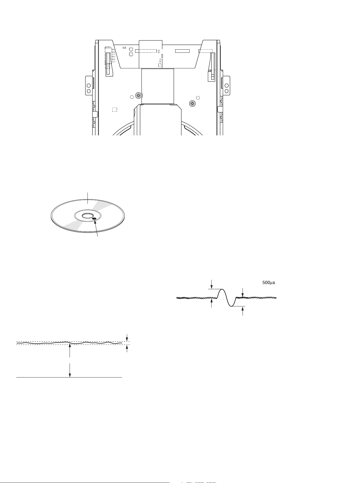
8-1. DVD JITTER ADJUSTMENT
1. Stick the provided small round sticker (0.1 mm thickness) at
the innermost position of a DVD disc as shown and make a
swayed DVD disc.
Signal recorded side
STICKER
Fig. 8-2
2. Play back the swayed DVD disc and press the F.F button
repeatedly until the pickup block reaches the outermost
position of its movable range. Next, press the PAUSE button.
3. Set the oscilloscope to the DC input mode and connect it to
the TP201 (HOT) and the TP102 (D.GND) on the MAIN
PCB.
4. Adjust the a screw and b screw alternately so that the AC
and DC level of the waveform is minimum. (DC level should
be less than 1.8 V, AC component should be minimum.)
JITTER ADJ
SCREW B
Fig. 8-1
2. Set the oscilloscope to the DC input mode and connect it to
the TP201 (HOT) and the TP102 (D.GND) on the MAIN
PCB.
3. Adjust the VR202 so that the DC level is minimum. (The DC
level should be less than 1.8 V)
8-3. CD TRACKING BALANCE
1. Set the VR110 at its center position prior to the adjustment.
2. Connect an oscilloscope to the TP150 (TE) on the MAIN
PCB.
3. Play back an ordinary CD-disc and then set it to the PAUSE
mode. If the play mode does not be engage, turn the VR110
at ±15 degrees. If the play mode does still not be engage
even when the VR110 is turned at ±15 degrees, turn the
VR110 at ± 30 degrees and try it again.
4. Observe the waveform and adjust it so that the level A of the
waveform is the same as level B.
A
B
500mV
Fig. 8-4
minimum
Less than 1.8V
Fig. 8-3
NOTE: If the SPINDLE MOTOR is replaced, this jitter
adjustment should be performed for proper performance.
8-2. SLICE LEVEL ADJUSTMENT
1. Play back an ordinary DVD disc (single side, one layer) and
press the F.F button repeatedly until the pickup block reaches
almost the center position of its movable range.
1-10

8-4 AS Adjustment
CAUTION :
Do not see the laser pick-up! Cover the laser pick-up unit
while AS adjustment.
8‑4AS8‑4AS
8‑4AS
8‑4AS8‑4AS
注意注意
注意
注意注意
LaserLaser
Laser
LaserLaser
はは
は
はは
調整調整
調整
調整調整
::
:
::
光を直接見ると目を傷める恐れがあります。光を直接見ると目を傷める恐れがあります。
光を直接見ると目を傷める恐れがあります。
光を直接見ると目を傷める恐れがあります。光を直接見ると目を傷める恐れがあります。
LaserLaser
が点灯しますので必ずが点灯しますので必ず
Laser
が点灯しますので必ず
LaserLaser
が点灯しますので必ずが点灯しますので必ず
LaserLaser
Laser
LaserLaser
ASAS
調整の際に調整の際に
AS
調整の際に
ASAS
調整の際に調整の際に
光を遮蔽して下さい。光を遮蔽して下さい。
光を遮蔽して下さい。
光を遮蔽して下さい。光を遮蔽して下さい。
Adjustment point : VR120, VR121
Test point : TP107(+), TP120 (+) TP105 (GND)
Equipment : Digital Multi Meter (DC voltage)
1. Press the mains switch (POWER BUTTON) while depressing
the PLAY button and STOP button.
2. Status will be on the TEST mode 2 and FL display shows
<TEST 2>. After a couple of seconds FL display shows
<TEST2 OK>.
3. Press the
button. Then the FL display shows <E3 02>
and the status will be in AS adjustment mode.
4. Measure the DC voltage at the test point TP107.
5. Press the
button again. Then the DVD laser will light ON
and the FL display shows <E3 00>.
6. Press the button again. Then the CD laser will light ON
and the FL display shows <E3 01>.
7. Adjust the voltage at the test point TP120 by VR121, that the
value must be same as TP107 (10mV) value measured on
#4. process.
8. Press the
button twice of time. Then the DVD laser will
light ON and the FL display shows <E3 00>.
9. Measure the DC voltage at the status DVD laser light ON.
Adjust the voltage at that status 35mV (±10mV) lower than
“CD laser light ON “ status by the trim resister VR120.
10.Press the
button again. Confirm the DC voltage at the
status CD laser light ON.
(DC voltage must be 35mV higher than the status DVD
laser light ON.)
11.Power OFF the mains switch (POWER BUTTON).
調整個所:VR120,VR121
テストポイント:TP107(+),TP120(+)TP105(GND)
測定器:デジタルマルチメーター
PLAYPLAY
1.
PLAYボタンと
PLAYPLAY
して下さい。
テストモ−ドテストモ−ド
2.
テストモ−ド
テストモ−ドテストモ−ド
され、数秒後[
ボタンを押し、
3.
ディスプレイには[
TP107TP107
4.
TP107のDC電圧を測定し記録します。
TP107TP107
ボタンを押し、DVD 用Laser を点灯させます。ディス
5.
プレイには[
で下さい。
ボタンを押し、CD 用 Laser を点灯させます。ディスプ
6.
レイには[
VR121VR121
7.
VR121を回し
VR121VR121
と同じ値(±10mV)に調整します。
ボタンを2回押し、
8.
スプレイには[
9. このときの電圧がCDLaser点灯時のDC電圧より35mV(±
10mV)低くなるように、
ボタンを押し、C
10.
レイには[
Laser点灯時より35mV高くなっていることを確認してくださ
い。
11.電源スイッチを押して、電源を切ります.
STOPSTOP
STOPボタンを押しながら、電源スイッチを押
STOPSTOP
22
2に入り、ディスプレイには[
22
TEST2OKTEST2OK
TEST2OK]と表示されます。
TEST2OKTEST2OK
ASAS
((
反反
射射
光光
))
AS
(
反
ASAS
((
反反
E302E302
E302]と表示されます。
E302E302
E300E300
E300]と表示されますが、何もせず次に進ん
E300E300
E301E301
E301]と表示されます。
E301E301
TP120TP120
TP120の電圧を4.にて測定した
TP120TP120
DVDDVD
DVD
DVDDVD
E300E300
E300]と表示されます。
E300E300
VR120VR120
VR120の半固定抵抗を調整します。
VR120VR120
DD
用用
LaserLaser
D
用
Laser
DD
用用
LaserLaser
E301E301
E301]と表示されます。この時、DC電圧がDVD用
E301E301
調整モード調整モード
射
光
)
調整モードに入ります。
射射
光光
))
調整モード調整モード
用用
LaserLaser
用
Laser
用用
LaserLaser
を点灯を点灯
を点灯させます。ディスプ
を点灯を点灯
TEST2TEST2
TEST2]と表示
TEST2TEST2
TP107TP107
TP107のDC電圧
TP107TP107
を点灯を点灯
を点灯させます。ディ
を点灯を点灯
1-11
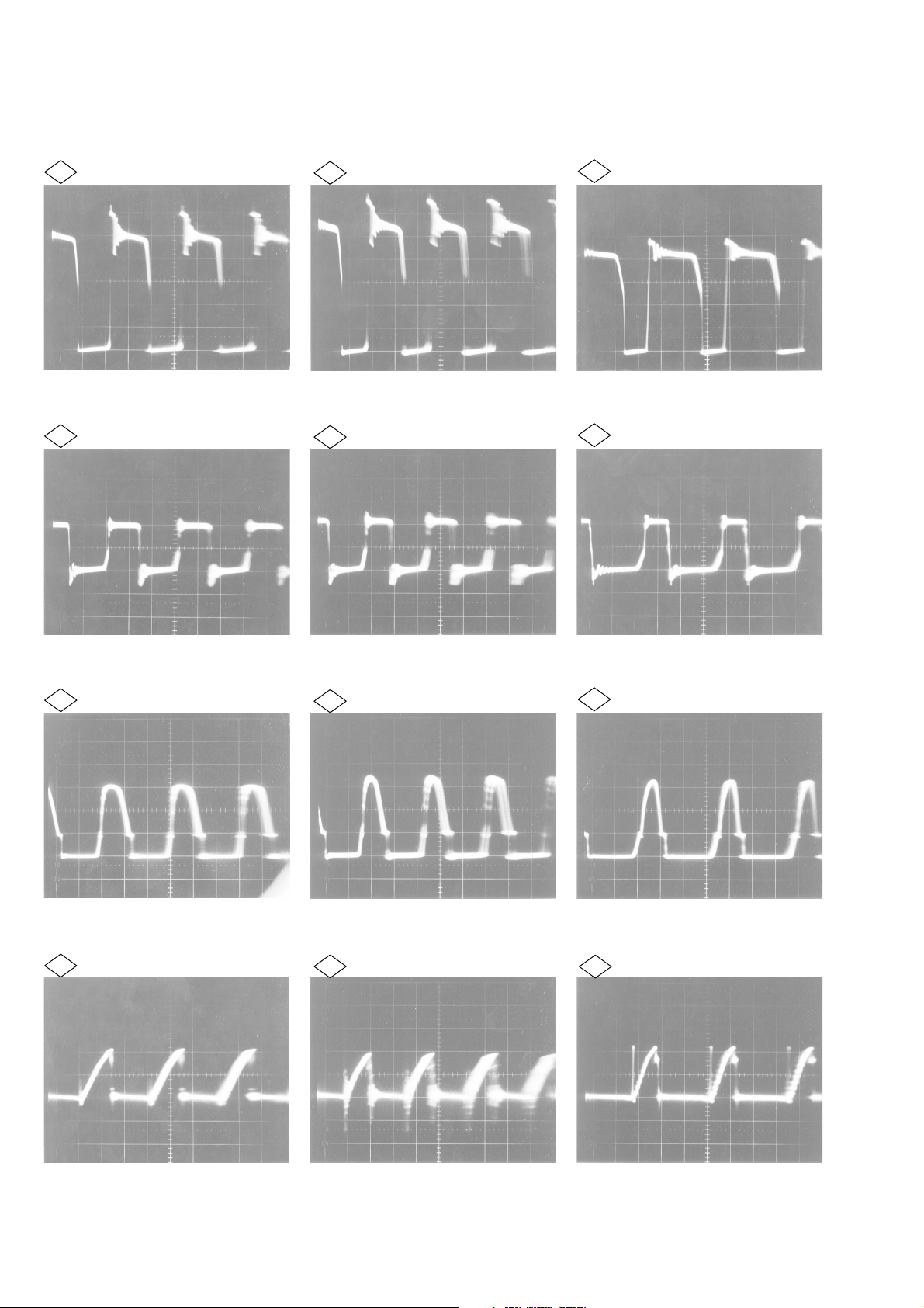
9. WAVEFORM
Power requirements (Refer the circuit diagram page 1-25 and 1-26)
100V AC 120V AV 220V AC
50V 5µsec 50V 5µsec 50V 5µsec
1
2
10V 5µsec 10V 5µsec 10V 5µsec
1
2
1
2
5V 5µsec 5V 5µsec 5V 5µsec
3
0.1V 5µsec 0.1V 5µsec 0.1V 5µsec
4
3
4
3
4
1-12
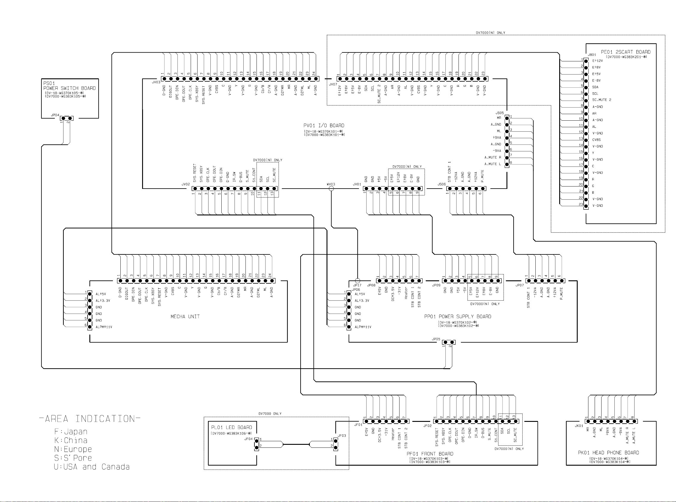
1.10 WARNINGS
1-13 1-14
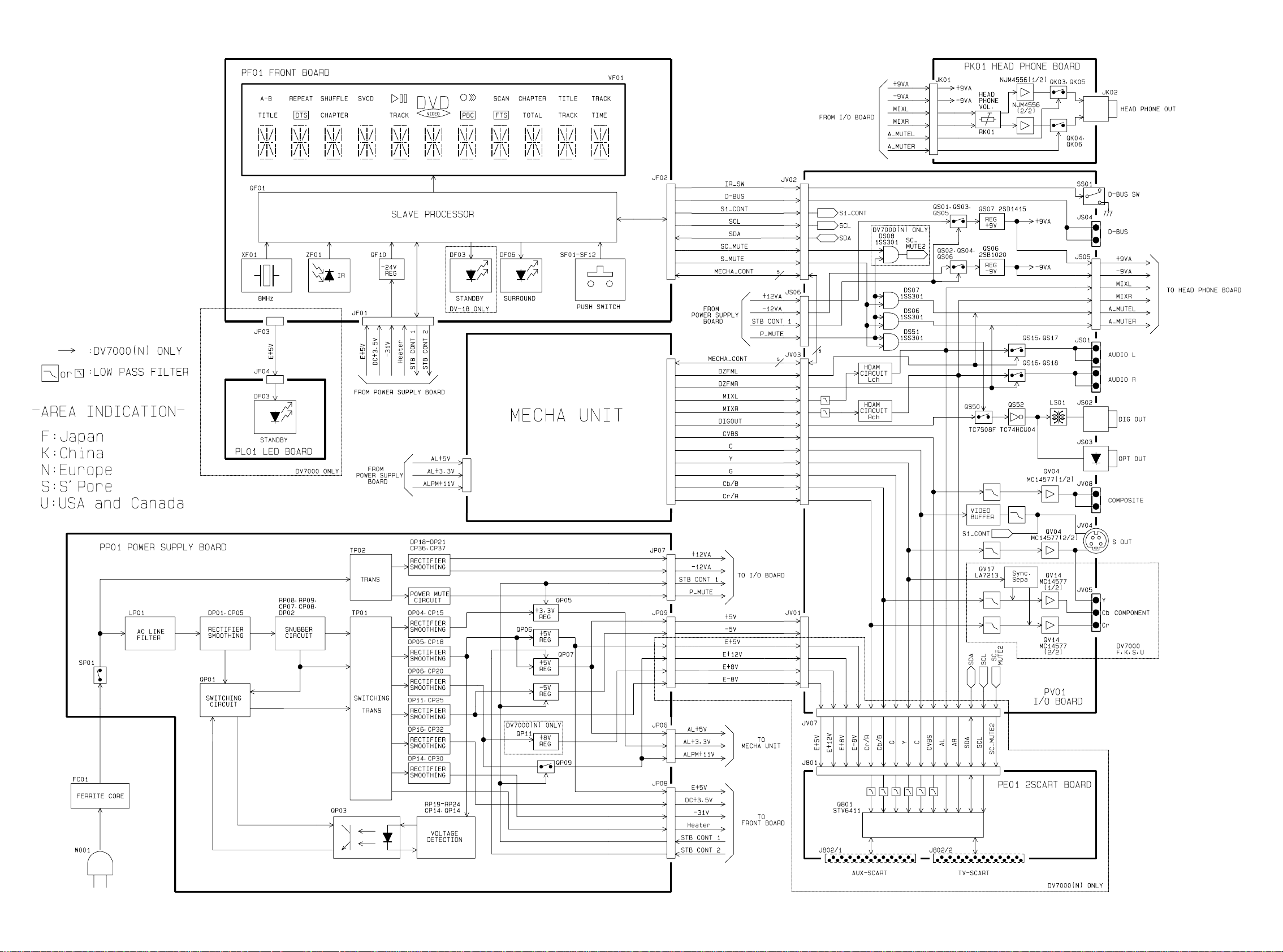
1.11 BLOCK DIAGRAM
1-15 1-16
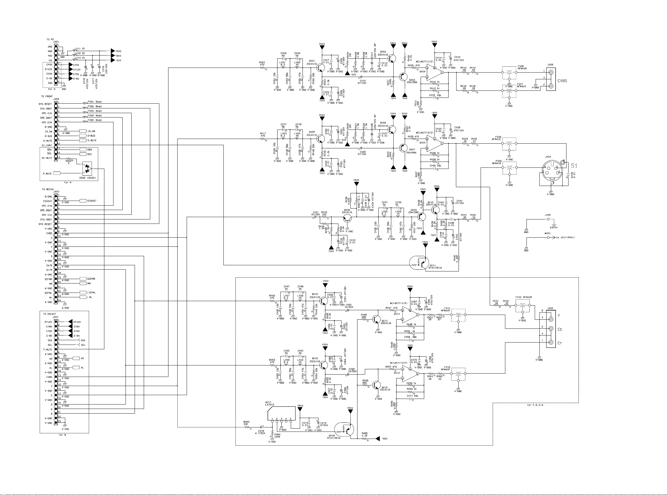
1.12 SCHEMATIC DIAGRAM AND PARTS LOCATION
1-17 1-18
 Loading...