


Service
Manual
LC3050 /N1B
LCD TV
TABLE OF CONTENTS |
|
SECTION |
PAGE |
PRODUCT SPEC. ....................................................................................................................... |
1 |
SAFETY PRECAUTIONS ............................................................................................................ |
2 |
SERVICING PRECAUTIONS ...................................................................................................... |
3 |
DISASSEMBLY PROCEDURE .................................................................................................... |
4 |
PARTS LIST ............................................................................................................................... |
10 |
MECHANICAL EXPLODED VIEW .............................................................................................. |
11 |
TROUBLE SHOOTING .............................................................................................................. |
12 |
WIRE DRESSING ...................................................................................................................... |
17 |
ADJUSTMENT INSTRUCTION WITH DEFAULT FACTORY DATA ........................................... |
19 |
PCB LAYOUT ............................................................................................................................ |
22 |
SCHEMATIC DIAGRAM ............................................................................................................ |
27 |
BLOCK DIAGRAM ..................................................................................................................... |
28 |
CONNECTION DIAGRAM ......................................................................................................... |
29 |
WAVE FORM ............................................................................................................................. |
30 |
FACTORY SPARE PARTS LIST ................................................................................................ |
41 |
Please use this service manual with referring to the user guide (D.F.U) without fail.
LC3050
LC3050
Part no. 90M47AW855010 First Issue 2004.05 ecm

MARANTZ DESIGN AND SERVICE
Using superior design and selected high grade components, MARANTZ company has created the ultimate in stereo sound. Only original MARANTZ parts can insure that your MARANTZ product will continue to perform to the specifications for which it is famous.
Parts for your MARANTZ equipment are generally available to our National Marantz Subsidiary or Agent.
ORDERING PARTS :
Parts can be ordered either by mail or by Fax.. In both cases, the correct part number has to be specified. The following information must be supplied to eliminate delays in processing your order :
1.Complete address
2.Complete part numbers and quantities required
3.Description of parts
4.Model number for which part is required
5.Way of shipment
6.Signature : any order form or Fax. must be signed, otherwise such part order will be considered as null and void.
USA
MARANTZ AMERICA, INC
1100 MAPLEWOOD DRIVE ITASCA, IL. 60143
USA
PHONE : 630 - 741 - 0300 FAX : 630 - 741 - 0301


 AMERICAS
SUPERSCOPE TECHNOLOGIES, INC.
MARANTZ PROFESSIONAL PRODUCTS 2640 WHITE OAK CIRCLE, SUITE A AURORA, ILLINOIS 60504 USA
PHONE : 630 - 820 - 4800
FAX : 630 - 820 - 8103
AUSTRALIA
QualiFi Pty Ltd,
24 LIONEL ROAD,
MT. WAVERLEY VIC 3149 AUSTRALIA
PHONE : +61 - (0)3 - 9543 - 1522 FAX : +61 - (0)3 - 9543 - 3677
NEW ZEALAND
WILDASH AUDIO SYSTEMS NZ
14 MALVERN ROAD MT ALBERT AUCKLAND NEW ZEALAND PHONE : +64 - 9 - 8451958
FAX : +64 - 9 - 8463554
JAPAN Technical
MARANTZ JAPAN, INC.
35- 1, 7- CHOME, SAGAMIONO SAGAMIHARA - SHI, KANAGAWA JAPAN 228-8505
PHONE : +81 42 748 1013 FAX : +81 42 741 9190
EUROPE / TRADING
MARANTZ EUROPE B.V.
P. O. BOX 8744, BUILDING SILVERPOINT BEEMDSTRAAT 11, 5653 MA EINDHOVEN THE NETHERLANDS
PHONE : +31 - 40 - 2507844
FAX : +31 - 40 - 2507860


 AUSTRALIA
TECHNICAL AUDIO GROUP PTY, LTD
43-53 Bridge Rd., STANMORE NSW 2048 AUSTRALIA
PHONE : +61 - (0)2 - 9519 - 0900
FAX : +61 - (0)2 - 9519 - 0600
THAILAND
MRZ STANDARD CO., LTD
746 - 754 MAHACHAI ROAD., WANGBURAPAPIROM, PHRANAKORN, BANGKOK, 10200 THAILAND
PHONE : +66 - 2 - 222 9181
FAX : +66 - 2 - 224 6795
TAIWAN
PAIYUING CO., LTD.
6 TH FL NO, 148 SUNG KIANG ROAD, TAIPEI, 10429, TAIWAN R.O.C. PHONE : +886 - 2 - 25221304
FAX : +886 - 2 - 25630415
CANADA
MARANTZ CANADA INC.
5-505 APPLE CREEK BLVD. MARKHAM, ONTARIO L3R 5B1 CANADA
PHONE : 905 - 415 - 9292 FAX : 905 - 475 - 4159
HONG KONG
Jolly ProAudio Broadcast Engineering Ltd.
UNIT 2, 10F, WAH HUNG CENTRE,
41 HUNG TO ROAD, KWUN TONG, KLN., HONG KONG
PHONE : 852 - 21913660
FAX : 852 - 21913990
SINGAPORE
WO KEE HONG DISTRIBUTION PTE LTD
No.1 JALAN KILANG TIMOR #08-03 PACIFIC TECH CENTRE SINGAPORE 159303
PHONE : +65 6376 0338
FAX |
: +65 6376 0166 |
MALAYSIA
WO KEE HONG ELECTRONICS SDN. BHD.
2ND FLOOR BANGUNAN INFINITE CENTRE LOT 1, JALAN 13/6, 46200 PETALING JAYA SELANGOR DARUL EHSAN, MALAYSIA PHONE : +60 - 3 - 7954 8088
FAX : +60 - 3 - 7954 7088
KOREA
MK ENTERPRISES LTD.
ROOM 604/605, ELECTRO-OFFICETEL, 16-58, 3GA, HANGANG-RO, YONGSAN-KU, SEOUL KOREA
PHONE : +822 - 3232 - 155
FAX : +822 - 3232 - 154
SHOCK, FIRE HAZARD SERVICE TEST :
CAUTION : After servicing this appliance and prior to returning to customer, measure the resistance between either primary AC cord connector pins ( with unit NOT connected to AC mains and its Power switch ON ), and the face or Front Panel of product and controls and chassis bottom.
Any resistance measurement less than 1 Megohms should cause unit to be repaired or corrected before AC power is applied, and verified before it is return to the user/customer.
Ref. UL Standard No. 1492.
In case of difficulties, do not hesitate to contact the Technical
Department at above mentioned address.
040401ECM
PRODUCT SPEC.
Model |
LC3050 |
|
|
|
|
|
|
|
|
|
|
Main body |
Horizontal size |
850 mm |
|
Thickness |
244.6 mm |
|
|
|
|
|
|
Height |
540 mm |
|
Weight |
14.6 kg |
|
|
|
||||
|
|
|
|
|
|
Power requirements |
DC 24V/6.0A |
|
|
|
|
|
|
|
|
||
Television system |
PAL-BG, I, DK/ SECAM-BG, DK, L |
|
|||
|
|
|
|
||
Television programme |
VHF: 2~13 UHF: 21~69 Cable: S1~S41 |
|
|||
|
|
|
|
|
|
LCD Panel |
30” wide TFT LCD panel |
|
|
||
|
|
|
|
|
|
Power consumption |
MAX. 130W |
|
|
|
|
|
|
|
|
|
|
External antenna impedance |
75Ω |
|
|
|
|
|
|
|
|
|
|
Audio output |
10W + 10W |
|
|
|
|
|
|
|
|
|
|
|
*1 |
|
|
• S-VIDEO IN 1 |
|
|
• DVI-IN 1 |
|
|
||
External IN/OUT ports |
• HEADPHONE JACK 1 |
• PC IN 1 |
|
||
• PC AUDIO IN 1 |
• SCART 2 |
|
|||
|
|
||||
|
• POWER IN 1 |
|
|
• ANTENNA IN 1 |
|
|
• SUB WOOFER OUT 1 |
|
|
||
|
|
|
|
|
|
AC Power Adaptor |
AC 100-240V, 5.0A, 50/60Hz, |
|
|
||
OUTPUT : 24VDC., 6.0A |
|
|
|||
|
|
|
|||
|
|
|
|
|
|
*1 Compatible with HDCP. Supported Signals
•640 x 480P @ 60Hz •1280 x 720P @ 50/60Hz •1920 x 1080I @ 50/60Hz •720 x 480P @ 60Hz •720 x 576P @ 50Hz
Note: In some cases a signal on the LCD TV may not be displayed properly. The problem may be an inconsistency with standards from the source equipment (DVD, Set-top box, etc...). If you do experience such a problem please contact Marantz Service Center, Inc. and also the manufacturer of the source equipment.
SERVICE MANUAL |
PAGE:1 |
SAFETY PRECAUTIONS
!! Import ant Safety Notice !!
Many electrical and mechanical parts in this chassis have special safety-related characteristics.
These parts are identified by in the Schematic Diagram and Replacement Parts List.
It is essential that these special safety parts should be replaced with the same components as recommended in this manual to prevent Shock, Fire, or other Hazards.
Do not modify the original design without permission of manufacturer.
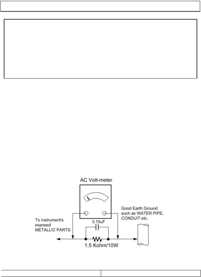
Leakage Current Hot Check (See below Figure) Plug the AC cord directly into the AC outlet.
Do not use a line Isolation Transformer during this check.
Connect 1.5K/10watt resistor in parallel with a 0.15uF capacitor between a known good earth ground (Water Pipe, Conduit, etc.) and the exposed metallic parts.
Measure the AC voltage across the resistor using AC voltmeter with 1000 ohms/volt or more sensitivity.
Reverse plug of the AC cord into the AC outlet and repeat AC voltage measurements for each exposed metallic part. Any voltage measured must not exceed 0.75 volt RMS, which is, corresponds to 0.5mA.
In case any measurement is out of the limits specified, there is possibility of shock hazard and the set must be checked and repaired before it is returned to the customer.
Leakage Current Hot Check circuit
SERVICE MANUAL |
PAGE:2 |

SERVICING PRECAUTIONS
CAUTION!!
Before servicing receivers covered by this service manual, read and follow the SAFETY PRECAUTIONS on page 2 of this publication.
General Servicing Precautions
1.Always unplug the receiver AC power cord from AC power source before;
a.Removing or reinstalling any component, circuit board module or any other receiver assembly.
b.Disconnecting or reconnecting any receiver electrical plug or other electrical connection.
c.Connecting a test substitute in parallel with an electrolytic capacitor in the receiver.
CAUTION!! A wrong part substitution or incorrect polarity installation of electrolytic capacitors may result in an explosion harzard.
2.Do not spray chemicals on or near this receiver or any of its assemblies.
3.Do not defect any plug/socket voltage interlocks with which receivers covered by this service manual might be equipped.
4.Always connect the test receiver ground lead to the receiver chassis ground before connecting the test receiver positive lead. Always remove the test receiver ground lead last. 5.Do not connect the test fixture ground strap to power supply heatsink in this receiver
Electrost atically Sensitive(ES) Devices
Some semiconductor(solid state) devices can be damaged easily by static electricity. Such components commonly are called Electrostatically Sensitive(ES) Device.Examples
Circuit Board Foil Repair
Excessive heat applied to the copper foil of any printed circuit board will weaken the adhesive that bonds the foil to the circuit board causing the foil th separate from or “lift-off” the board. The following guidelines and procedures should be flollowed whenever this condition is encountered.
At IC Connections
To repair a defective copper pattern at IC connections use the following procedure to install a jumper wire on the copper pattern side of the circuit board.(Use this technique only on IC connections.)
1.Carefully remove the damaged copper pattern with a sharp knife.(Remove only as much copper as absolutely necessary.)
2.Carefully scratch away the solder resist and acrylic coating(if used) from the end of the remaining coopper pattern.
3.Bend a small “U” in one end of a small guage jumper wire and carefully crimp it around the IC pin.
4.Route the jumper wire along the path of the out-away copper pattern and let it overlap the previously scraped end of the good copper pattern. Solder the overlapped area and clip off any excess jumper wire.
SERVICE MANUAL |
PAGE:3 |
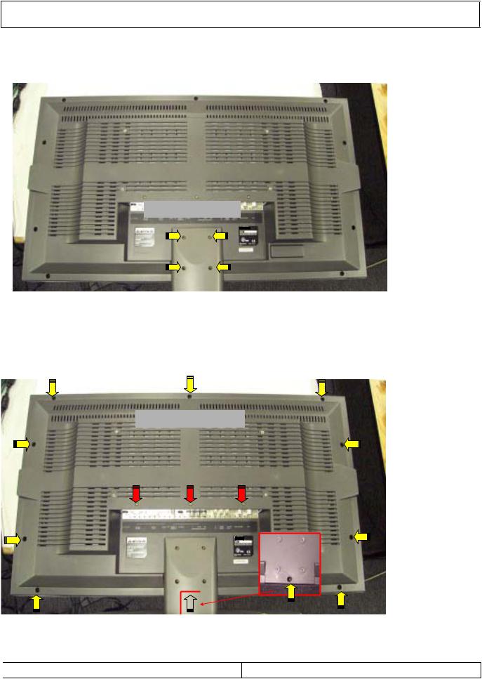
DISASSEMBLY PROCEDURE
Disassembly procedure 1).Back cover
Remove 4 screws
Remove 13 screws
SERVICE MANUAL |
PAGE:4 |
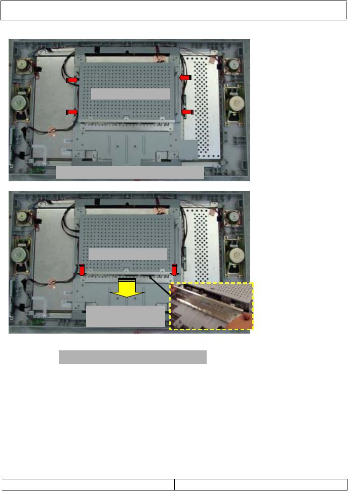
DISASSEMBLY PROCEDURE
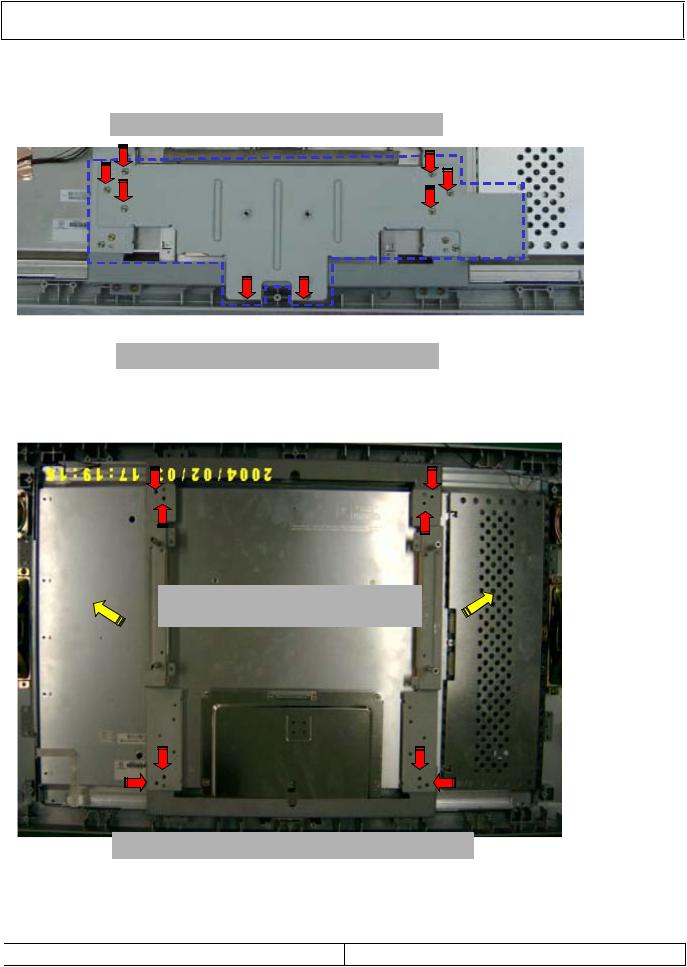
2).Metal plate & Rear chassis
Remove 4
Removal of rear metal chassis...
1. Remove 2
2.Slide away the metal plate
Removal of Terminal metal plate
SERVICE MANUAL |
PAGE:5 |
DISASSEMBLY PROCEDURE
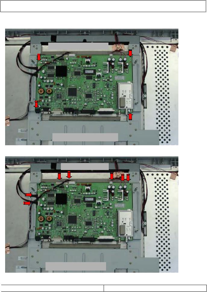
3).Main PWB & Connectors
Remove 4 MainCB screws
Removal of Main P C ...
Remove 7
Removal of MainPCB
SERVICE MANUAL |
PAGE:6 |
DISASSEMBLY PROCEDURE
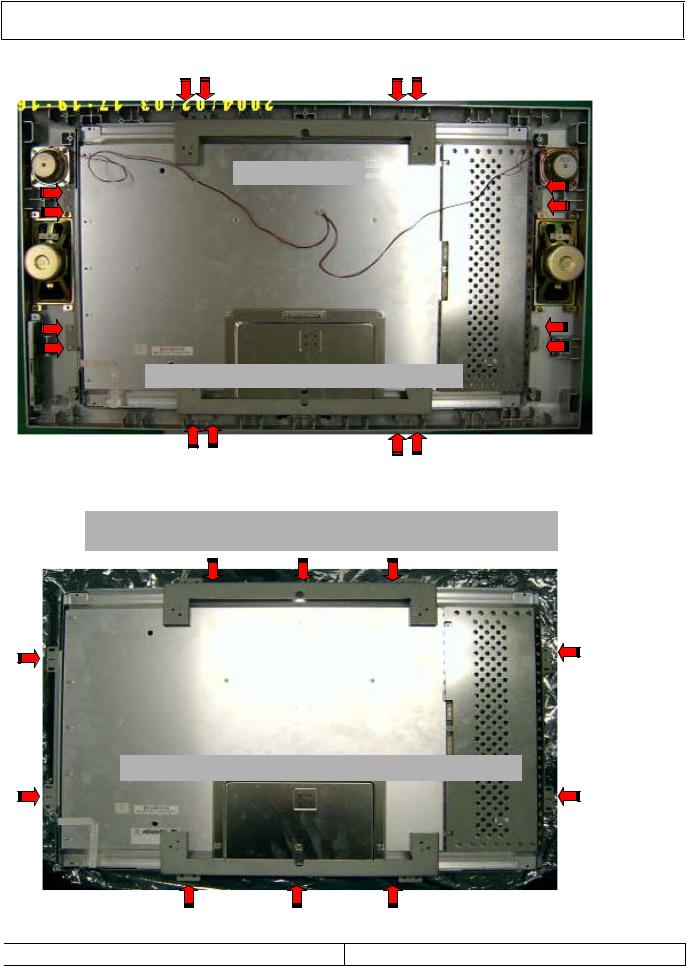
4).LCD Panel chassis
Remove 8 screws, then take off sub-metal
Removal of LCD Module sub-bracket
Remove 8 screws, then take off two vertical mountmetal brackets
Removal of LCD Module vertical brackets
SERVICE MANUAL |
PAGE:7 |
DISASSEMBLY PROCEDURE
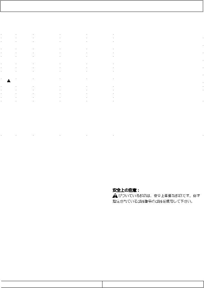
5-1). LCD Moul
Remove18 screw
Removal of LCD Module brackets
Remove 4 brackets, then lift out LCD Module (move all wire looms away which are attached to the module)
Removal of LCD Panel module mounting brackets
SERVICE MANUAL |
PAGE:8 |
DISASSEMBLY PROCEDURE
5-2).LCD Module
Front mask remains after removing LCD Module
SERVICE MANUAL |
PAGE:9 |
EXPLODED VIEW PARTS LIST
POS. NO. |
VERS. |
PART NO. |
PART NO. |
PARTS NAME |
DESCRIPTION |
|
COLOR |
(FOR EUR) |
(MJI) |
|
|||
A |
/N1B |
00M47AW248510 |
00M47AW248510 |
PANEL ASSY |
FRONT PANEL ASSY |
AYCALT32A01K |
B |
/N1B |
00M47AW128510 |
00M47AW128510 |
STAND ASSY |
STAND ASSY |
AYSTLT32A01E |
3 |
/N1B |
90M-QK000120R |
90M-QK000120R |
SPEAKER |
10W 8OHM |
610-005B |
4 |
/N1B |
90M-QJ000020R |
90M-QJ000020R |
SPEAKER |
20W 8OHM |
610-005A |
5 |
/N1B |
90M-ZZ002580R |
90M-ZZ002580R |
PCB ASSY |
CONTROL PCB ASSY & LED PCB ASSY |
AYCOLT32A01B |
8 |
/N1B |
90M47AW154010 |
90M47AW154010 |
KNOB |
ON/OFF, MENU, CH, VOL, TV/AV |
404-004C |
9 |
/N1B |
90M-KZ000030R |
90M-KZ000030R |
UNIT KIT |
LCD PANEL 29" CMO V296W1-L** |
PANV296W1L01 |
15 |
/N1B |
90M-ZZ002590R |
90M-ZZ002590R |
PCB ASSY |
MAIN PCB ASSY |
AYMALT35A01E |
18 |
/N1B |
90M47AW248020 |
90M47AW248020 |
PANEL |
REAR PANEL LT-30*EP/*LP |
AYBCLT32A01D |
|
|
|
|
PACKING |
|
|
|
/N1B |
00M47AW851310 |
00M47AW851310 |
USER GUIDE |
USER GUIDE/N1B |
500-031B |
|
/N1B |
00MZK47AW0010 |
00MZK47AW0010 |
UNIT KIT |
REMOTE CONTROLLER RC3050LC |
510-004L |
|
/N1B |
90M-AA000050R |
90M-AA000050R |
AC ADAPTER |
24V/6.0A 1.8M |
620-004A |
|
/N1B |
90M-ZC000400R |
90M-ZC000400R |
MAINS CORD |
VDE KKP-4819R |
621-001B |
|
|
|
|
NOT STANDARD |
SPARE PART |
|
|
|
nsp |
00M47AW801010 |
PACKING CASE |
PACKING CASE LC3050/N1B |
300-010U |
|
|
nsp |
90M47AW809010 |
CUSHION |
CUSHION TOP L |
310-009E |
|
|
nsp |
90M47AW809020 |
CUSHION |
CUSHION TOP R |
310-009F |
|
|
nsp |
90M47AW809030 |
CUSHION |
CUSHION BOTTOM L |
310-010E |
|
|
nsp |
90M47AW809040 |
CUSHION |
CUSHION BOTTOM R |
310-010F |
|
|
|
|
|
|
|
NOTE : “nsp” PARTS IS LISTED FOR REFERENCE ONLY, MARANTZ WILL NOT SUPPLY THESE PARTS.
ELECTRICAL PARTS LIST
POS. NO. |
VERS. |
PART NO. |
PART NO. |
PARTS NAME |
DISCRIPTION |
|
COLOR |
(FOR EUR) |
(MJI) |
|
|||
|
|
|
|
MAIN PCB |
|
|
P1001 |
|
90M-YT003940R |
90M-YT003940R |
TERMINAL |
RGB21PIN,VP 381-091B |
0JASCART000D |
P1002 |
|
90M-YT003940R |
90M-YT003940R |
TERMINAL |
RGB21PIN,VP 381-091B |
0JASCART000D |
P1003 |
|
90M-YT003880R |
90M-YT003880R |
TERMINAL |
RCA-1406(W/R) |
0JAGE14060BD |
P1006 |
|
90M-YT003900R |
90M-YT003900R |
TERMINAL |
ST-215 |
0JAKKST215BD |
P1007 |
|
90M-YT003900R |
90M-YT003900R |
TERMINAL |
ST-215 |
0JAKKST215BD |
P1008 |
|
90M-YT003870R |
90M-YT003870R |
TERMINAL |
WOOFER, RCA-103 |
0JAGN10300BD |
P1009 |
|
90M-YT003910R |
90M-YT003910R |
TERMINAL |
S-VHS, PJ6046G |
0JAPK6046GBD |
P801 |
|
90M-YT003920R |
90M-YT003920R |
TERMINAL |
4P POWER |
0JASYDC4P0BD |
P901 |
|
90M-YT003890R |
90M-YT003890R |
TERMINAL |
DAH-15RF-4B4 |
0JADM15RF00D |
P902 |
|
90M-YT003930R |
90M-YT003930R |
TERMINAL |
DVI-CON |
0JASYDVI29BD |
TU1001 |
|
90M-AV000390R |
90M-AV000390R |
TUNER |
2IN1 TAFD-S212D |
0TULGS212DBD |
NOTE ON SAFETY :
Symbol  Fire or electrical shock hazard. Only original parts should be used to replaced any part marked with symbol
  . Any other component substitution (other than original type), may increase risk of fire or electrical shock hazard.
SERVICE MANUAL |
PAGE:10 |

MECHANICAL EXPLODED VIEW
26 |
35 |
|
|
|
|
|
33 |
|
|
|
|
|
|
|
|
|
16 |
|
28 |
|
|
|
|
33 |
15 |
|
|
|
|
|
|
|
|
|
|
|
|
|
26 |
31 |
|
32 |
|
|
|
|
|
|
9 |
31 |
12 |
|
|
|
|
|
33 |
|
|
|
|
18 |
||
|
|
|
|
|
|
|
||
|
|
|
|
11 |
|
|
|
|
|
|
|
|
|
32 |
|
|
|
|
|
|
|
26 |
|
|
|
|
|
10 |
|
|
|
13 |
33 |
17 |
|
|
|
|
|
|
|
|||
2 |
1 |
|
|
|
|
14 |
|
30 |
|
|
|
|
|
|
|
||
|
|
|
|
|
|
|
|
27 |
|
|
|
|
31 |
26 |
|
|
21 |
|
|
|
|
|
|
19 |
||
|
|
|
|
|
|
|
|
|
|
|
|
|
10 |
|
|
|
20 |
|
|
|
|
|
|
|
|
|
|
|
|
31 |
11 |
|
|
|
|
|
|
|
|
|
|
|
|
|
|
33 |
|
|
|
25 |
24 |
22 |
|
|
A |
|
|
|
|
|
|
34 |
|
|
|
|
|
|
|
|
|
|
27 |
5 |
5 |
|
|
|
|
|
|
|
6 |
8 |
|
|
|
|
29 |
|
|
|
3 |
|
|
|
||
|
|
|
|
|
|
23 |
||
|
|
|
|
|
|
|
||
|
|
|
|
|
|
|
|
|
|
|
|
|
4 |
|
|
|
B |
|
|
|
|
|
|
|
|
|
|
|
|
|
26 |
|
|
|
|
SERVICE MANUAL |
PAGE:11 |
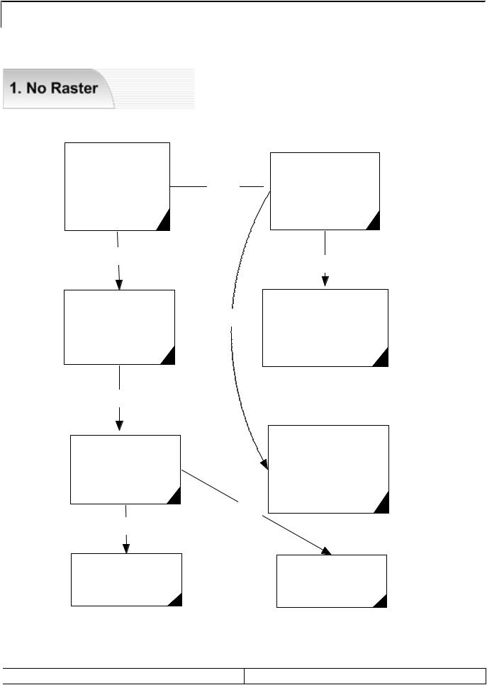
TROUBLE SHOOTING
No Raster?
(Real Black?)
NO
Check P441
Connector & Cable
OK?
YES
Check
P441 Pin #3~6
Panel VCC
YES
Replace LCD module
SERVICE MANUAL
Check P952,951
YES  Pin #10~15 : VCC
Pin #4 : On/Off
OK?
YES
NO |
Replace Inverter |
|
Cable or module |
Check appropriate circuit
(Power suply
& u-Com control )
NO
Check or Replace
IC803
PAGE:12
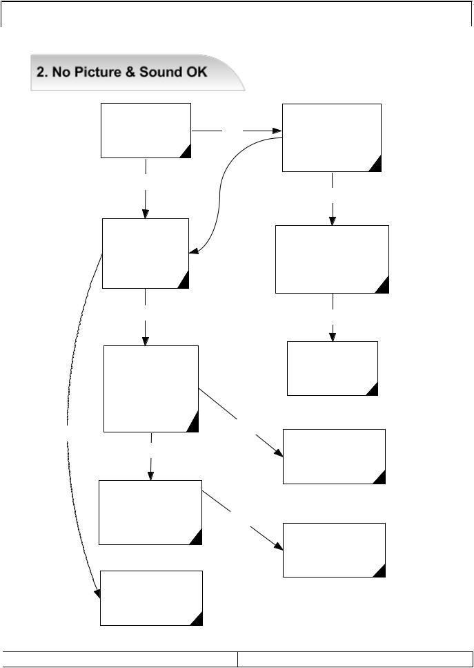
TROUBLE SHOOTING
Is OSD OK? |
NO |
YES NO
Check
IC271 =1.8V Reg
IC272 =3.3V Reg
pin #32,39
H.V Sync OK?
YES
|
IC201 |
|
|
Each and all |
|
|
video Input Check |
|
|
Pin #78,80,82 |
|
|
=component |
|
|
96 = RF CVBS |
|
|
97 +A/v |
NO |
NO |
100,102 =YC |
|
YES |
|
|
|
|
|
|
Check |
|
|
AL201 ~206& |
|
|
A;L208 ~210 Oof |
NO |
|
IC201Video Data out |
|
|
OK? |
|
|
Check |
|
|
IC271,272 DC Reg |
|
|
In/OuT Power Line |
|
Check IC101
Pin #378(clock)
Pin #326,301(Sync)
OK?
YES
Check IC402
Pin #1,9,17,26,34,44 (vcc)
pin #31 =(Clock) OK?
YES
Fasten P441
Cable & Connector
Check External
Video Soure
Replace IC201
SERVICE MANUAL |
PAGE:13 |
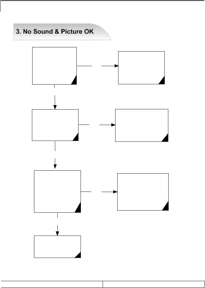
TROUBLE SHOOTING
Check IC601
Audio Inputs Pin#47.48=PC L.R
50.51=Compo L.R NO 56.57=A/V L.R
60=RF Mono OK?
YES
Check external Input audio source
Check IC601 Outputs |
|
|
Pin #27.28=L.R Out |
NO |
|
30=Woofer Out |
||
|
||
OK? |
|
YES
Check IC651.652 Audio outputs
Each pin #7.#11 NO OK?
YES
Check Speaker
and Replacement
Check IC601 VCC
and Replacement
Check IC605
Pin #10 Vcc &
Pin #8 Mute
(Pin #8 Low=Mute)
and Replacement
SERVICE MANUAL |
PAGE:14 |
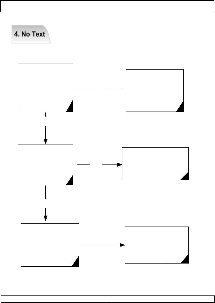
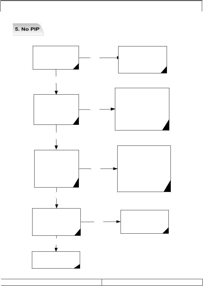
TROUBLE SHOOTING
Check IC601
Pin#21
(CVBS Sibnal) NO
OK?
YES
Check Pin #57 ~ 60
of IC 101 NO
(R,G,B FB)
YES
Check Pin #67,70,72 |
|
73 of IC201 |
NO |
(R,G,B FB) |
Check CVBS Signal  from Pin #67 of IC201 to Pin #21 of IC101
Replace IC01
Check RF Source gain
SERVICE MANUAL |
PAGE:15 |
TROUBLE SHOOTING
Check
IC271,272,821 NO
In/Out Voltage
YES
Check |
|
AL201~206& |
NO |
AL208~210 |
|
IC201 Video Data out |
|
OK? |
|
YES
Check AL301~306
IC301 Video Data out NO OK?
YES
DC Reg
In/Out Power Line
Check & Replacement
IC201 Each and all
video Input Check Pin #78,80,82= Component 96=RF CVBS 98=A/V 100,102=Y/C
IC301 Each and all
Input Signals Check Pin #54,65,70 = RGB input 32,33,35,36,38,39, 41,42 = DVI Input
Check IC1151
Pin #1,2,12~15 (Sync) NO
& VCC
YES
Replacement
IC101
SERVICE MANUAL
Replace IC1151
Check VCC Line
& Replacement
PAGE:16
|
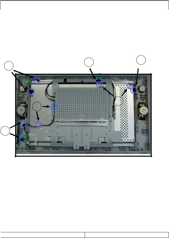
WIRE DRESSING |
Wire Dressing |
|
Note : Using Acetate Tape |
No1, No3, No4, No5. |
Using Copper Tape |
No2, No6 (Conducted tape) |
4 |
3 |
1 |
|
||
|
|
2
6
5
SERVICE MANUAL |
PAGE:17 |
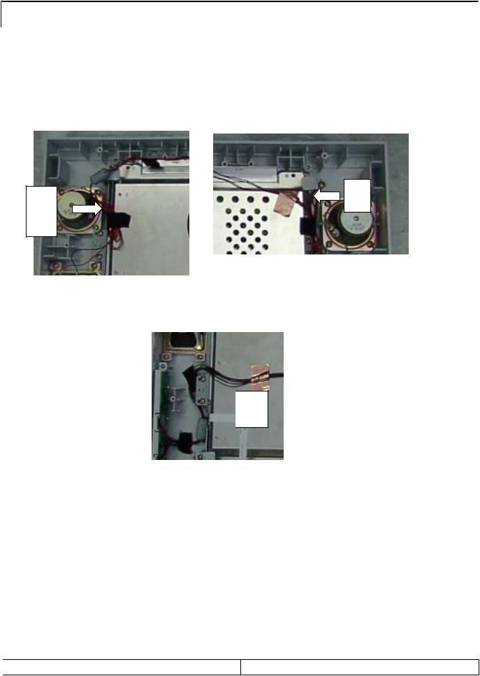
WIRE DRESSING
1)Wire Dressing for Left speaker & woofer speaker. ( No.1)
2)Wire Dressing for Right speaker & Woofer speaker. ( No.2 )
3)Wire Dressing for Key control & Power Indicator with IR receiver ( No.3 )
2 |
1 |

 3
3
SERVICE MANUAL |
PAGE:18 |
 Loading...