

MacDon M Series, M150, M200, M100 Unloading And Assembly Instructions

M Series Self-Propelled Windrower
Published: September, 2010
UNLOADING AND ASSEMBLY
CONTAINER SHIPMENTS
INSTRUCTIONS
for
Form 169242 Revision D
MACDON SELF PROPELLED AUGER HEADER
Form 169242 Revision D
MACDON SELF-PROPELLED WINDROWER

INTRODUCTION
This instructional manual describes the unloading, set-up and pre-delivery requirements for the MacDon M Series
Self-Propelled Windrowers.
Use the Table of Contents to guide you to specific areas.
Retain this instruction for future reference.
CAREFULLY READ ALL THE MATERIAL PROVIDED BEFORE ATTEMPTING TO UNLOAD, ASSEMBLE, OR
USE THE MACHINE.
TABLE OF CONTENTS
INTRODUCTION ........................................................................................................................................................ 1
GENERAL SAFETY ................................................................................................................................................... 3
RECOMMENDED TORQUES ................................................................................................................................... 5
A. GENERAL ............................................................................................................................................... 5
B. SAE BOLTS ............................................................................................................................................ 5
C. METRIC BOLTS ..................................................................................................................................... 5
D. FLARE TYPE HYDRAULIC FITTINGS .................................................................................................. 6
E. O-RING TYPE HYDRAULIC FITTINGS ................................................................................................. 6
ENGLISH/METRIC EQUIVALENTS .......................................................................................................................... 7
DEFINITIONS ............................................................................................................................................................ 7
STEP 1. UNLOAD CONTAINER .............................................................................................................................. 8
STEP 2. MOVE TO ASSEMBLY AREA ................................................................................................................... 8
A. CRANE METHOD .................................................................................................................................. 8
B. FORKLIFT METHOD .............................................................................................................................. 9
STEP 3. REMOVE WHEEL AND STEP ASSEMBLY ............................................................................................ 11
STEP 4. REMOVE DRIVE WHEELS ..................................................................................................................... 13
STEP 5. REMOVE PLATFORM / LIGHT ASSEMBLY .......................................................................................... 14
STEP 6. INSTALL LIGHT AND MIRROR ASSEMBLIES ...................................................................................... 15
STEP 7. REMOVE LEG ASSEMBLIES ................................................................................................................. 17
STEP 8. REMOVE WHEEL AND PLATFORM SUPPORT .................................................................................... 18
STEP 9. ASSEMBLE WINDROWER SUPPORT STAND ..................................................................................... 18
STEP 10.LIFT WINDROWER ONTO STAND ........................................................................................................ 19
A. CRANE METHOD ................................................................................................................................ 19
B. FORKLIFT METHOD ............................................................................................................................ 20
STEP 11.INSTALL LEGS ........................................................................................................................................ 21
STEP 12.INSTALL FRONT WHEELS ..................................................................................................................... 23
STEP 13.INSTALL CASTER WHEELS .................................................................................................................. 25
STEP 14.INSTALL HYDRAULICS ............................................................................................................ .............. 27
A. M150, M200 .......................................................................................................................................... 27
B. M100 ..................................................................................................................................................... 31
STEP 15.INSTALL PLATFORMS ........................................................................................................................... 34
STEP 16.INSTALL STEPS ...................................................................................................................................... 36
STEP 17.INSTALL TOOLBOX ................................................................................................................................ 36
STEP 18.INSTALL BATTERIES ............................................................................................................................. 37
A. M150, M200 .......................................................................................................................................... 37
B. M100 ..................................................................................................................................................... 38
STEP 19.PRIME HYDRAULIC SYSTEM ................................................................................................................ 39
STEP 20.START ENGINE ...................................................................................................................................... 41
STEP 21.CHECK TRACTION DRIVE ..................................................................................................................... 43
STEP 22.REMOVE WINDROWER FROM STAND ................................................................................................ 44
A. FACTORY STAND ............................................................................................................................... 44
B. FIELD CONSTRUCTED STAND.......................................................................................................... 44
Form 169242 Revision D
1

STEP 23.INSTALL AM/FM RADIO ......................................................................................................................... 45
STEP 24.INSTALL BEACONS ................................................................................................................................ 47
STEP 25. INSTALL SLOW MOVING VEHICLE (SMV) SIGN ................................................................................. 47
STEP 26.ATTACH HEADER ................................................................................................................................... 48
A. HEADER ATTACHMENT - D SERIES ................................................................................................. 48
B. HEADER ATTACHMENT - A SERIES ................................................................................................. 54
C. HEADER ATTACHMENT - R SERIES (M150, M200 ONLY) .............................................................. 58
STEP 27. LUBRICATE MACHINE ........................................................................................................................... 62
STEP 28.PROGRAM CAB DISPLAY MODULE (CDM).......................................................................................... 64
A. M150, M200 DETAILED PROGRAMMING INSTRUCTIONS .............................................................. 65
B. M100 DETAILED PROGRAMMING INSTRUCTIONS ......................................................................... 71
STEP 29.PERFORM HYDRAULIC PURGE ........................................................................................................... 76
STEP 30.PERFORM PRE-DELIVERY CHECKS ................................................................................................... 78
A. FINAL DRIVE LUBRICANT LEVEL ...................................................................................................... 78
B. TIRE PRESSURES AND BALLAST REQUIREMENTS ....................................................................... 78
I. Tire Pressures ............................................................................................................................. 78
II. Ballast Requirements .................................................................................................................. 78
C. ENGINE COOLANT ............................................................................................................................. 79
D. AIR CLEANER ...................................................................................................................................... 80
E. HYDRAULIC OIL LEVEL ...................................................................................................................... 80
F. FUEL SEPARATOR ............................................................................................................................. 81
G. GEAR BOX LUBRICANT LEVEL (M150, M200) .................................................................................. 81
H. A/C COMPRESSOR BELT ................................................................................................................... 81
I. FAN BELT (M100) ................................................................................................................................ 82
J. PERFORM SAFETY SYSTEM CHECKS ............................................................................................. 83
K. OPERATIONAL CHECKS .................................................................................................................... 84
I. Engine Warning Lights ................................................................................................................ 84
II. Start Engine ................................................................................................................................ 84
III. Engine Speed ............................................................................................................................. 84
IV. Guages and CDM Display .......................................................................................................... 84
V. Electrical ..................................................................................................................................... 84
VI. Operator’s Presence System Checks ......................................................................................... 85
VII. Exterior Lights ............................................................................................................................. 86
VIII. Interior Lights .............................................................................................................................. 89
IX. A/C and Heater ........................................................................................................................... 90
L. MANUALS ....................................................................................................................... ..................... 91
M. CAB INTERIOR .................................................................................................................. .................. 91
Form 169242 Revision D
2

GENERAL SAFETY
CAUTION
The following are general farm safety
precautions that should be part of your
operating procedure for all types of
machinery.
• Protect yourself.
• When assembling, operating and servicing
machinery, wear all the protective clothing
and personal safety devices that COULD
be necessary for the job at hand. Don't
take chances.
• You may need:
• Provide a first-aid kit for use in case of
emergencies.
• Keep a fire extinguisher on the machine.
Be sure the extinguisher is properly
maintained and be familiar with its proper
use.
• Keep young children away from machinery
at all times.
• Be aware that accidents often happen
when the Operator is tired or in a hurry to
get finished. Take the time to consider the
safest way. Never ignore warning signs of
fatigue.
o a hard hat.
o protective shoes with slip resistant
soles.
o protective glasses or goggles.
o heavy gloves.
o wet weather gear.
o respirator or filter mask.
A
B
o hearing protection. Be aware that
prolonged exposure to loud noise
can cause impairment or loss of
hearing. Wearing a suitable
hearing protective device such as
ear muffs (A) or ear plugs (B)
protects against objectionable or
loud noises.
• Wear close-fitting clothing
and cover long hair. Never
wear dangling items such
as scarves or bracelets.
• Keep hands, feet, clothing
and hair away from
moving parts.
• Never attempt to clear obstructions or
objects from a machine while the engine is
running.
• Keep all shields in place. Never alter or
remove safety equipment. Make sure
driveline guards can rotate independently
of the shaft and can telescope freely.
• Use only service and repair parts made or
approved by the equipment manufacturer.
Substituted parts may not meet strength,
design, or safety requirements.
Form 169242 Revision D
(continued next page)
3

• Do not modify the machine. Unauthorized
modifications may impair the function
and/or safety and affect machine life.
• Stop engine, and remove key from ignition
before leaving Operator's seat for any
reason. A child or even a pet could engage
an idling machine.
• Keep the area used for servicing
machinery clean and dry. Wet or oily floors
are slippery. Wet spots can be dangerous
when working with electrical equipment.
Be sure all electrical outlets and tools are
properly grounded.
• Use adequate light for the job at hand.
• Keep machinery clean. Do not allow oil or
grease to accumulate on service platforms,
ladders or controls. Clean machines before
storage.
• Never use gasoline, naphtha or any volatile
material for cleaning purposes. These
materials may be toxic and/or flammable.
• When storing machinery, cover sharp or
extending components to prevent injury
from accidental contact.
Form 169242 Revision D
4
RECOMMENDED TORQUES
A. GENERAL
The tables shown below give correct torque
values for various bolts and capscrews.
• Tighten all bolts to the torques specified in
chart unless otherwise noted throughout this
manual.
• Check tightness of bolts periodically, using
bolt torque chart as a guide.
• Replace hardware with the same strength
bolt.
• Torque figures are valid for non-greased or
non-oiled threads and heads unless otherwise
specified. Do not grease or oil bolts or
capscrews unless specified in this manual.
• When using locking elements, increase torque
values by 5%.
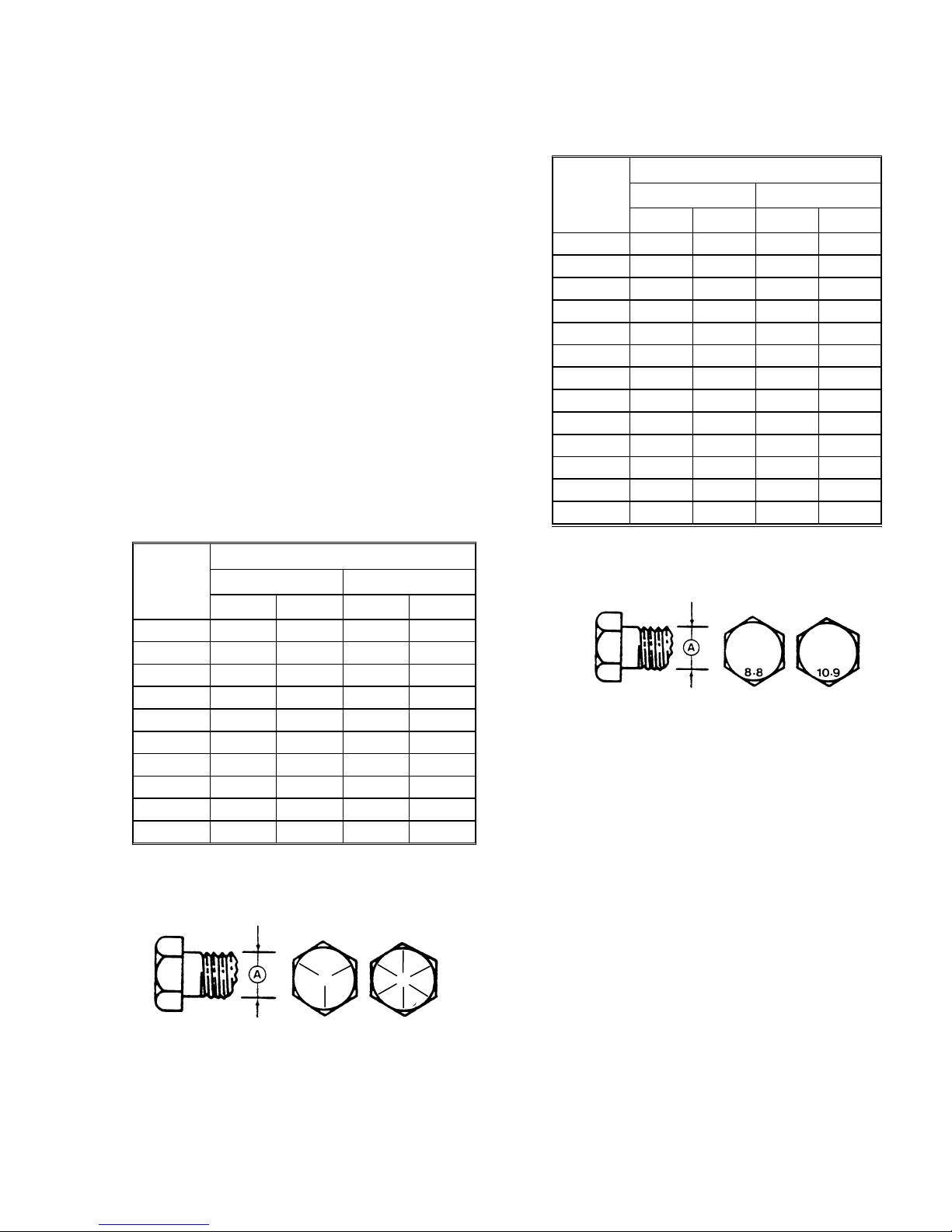
B. SAE BOLTS
NC BOLT TORQUE*
BOLT
DIA. "A"
in.
1/4 9 12 11 15
5/16 18 24 25
3/8 32 43 41
7/16 50 68 70 95
1/2 75 102 105 142
9/16 110 149 149 202
5/8 150 203 200 271
3/4
7/8 420 569 600 813
1 640 867 890 1205
* Torque categories for bolts and capscrews are identified by their
head markings.
SAE 5 SAE 8
ft·lbf N·m ft·lbf N·m
34
56
265 359
365 495
C. METRIC BOLTS
NC BOLT TORQUE*
BOLT
DIA. "A"
M3 0.4 0.5 1.3 1.8
M4 2.2 3 3.3 4.5
M5 4 6 7 9
M6 7 10 11 15
M8 18 25 26 35
M10 37 50 52 70
M12 66 90 92 125
M14 103 140 148 200
M16 166 225 229 310
M20 321 435 450 610
M24 553 750 774 1050
M30 1103 1495 1550 2100
M36 1917 2600 2710 3675
* Torque categories for bolts and capscrews are identified by their
head markings.
8.8 10.9
ft·lbf N·m ft·lbf N·m
SAE-5 SAE-8
Form 169242 Revision D
5
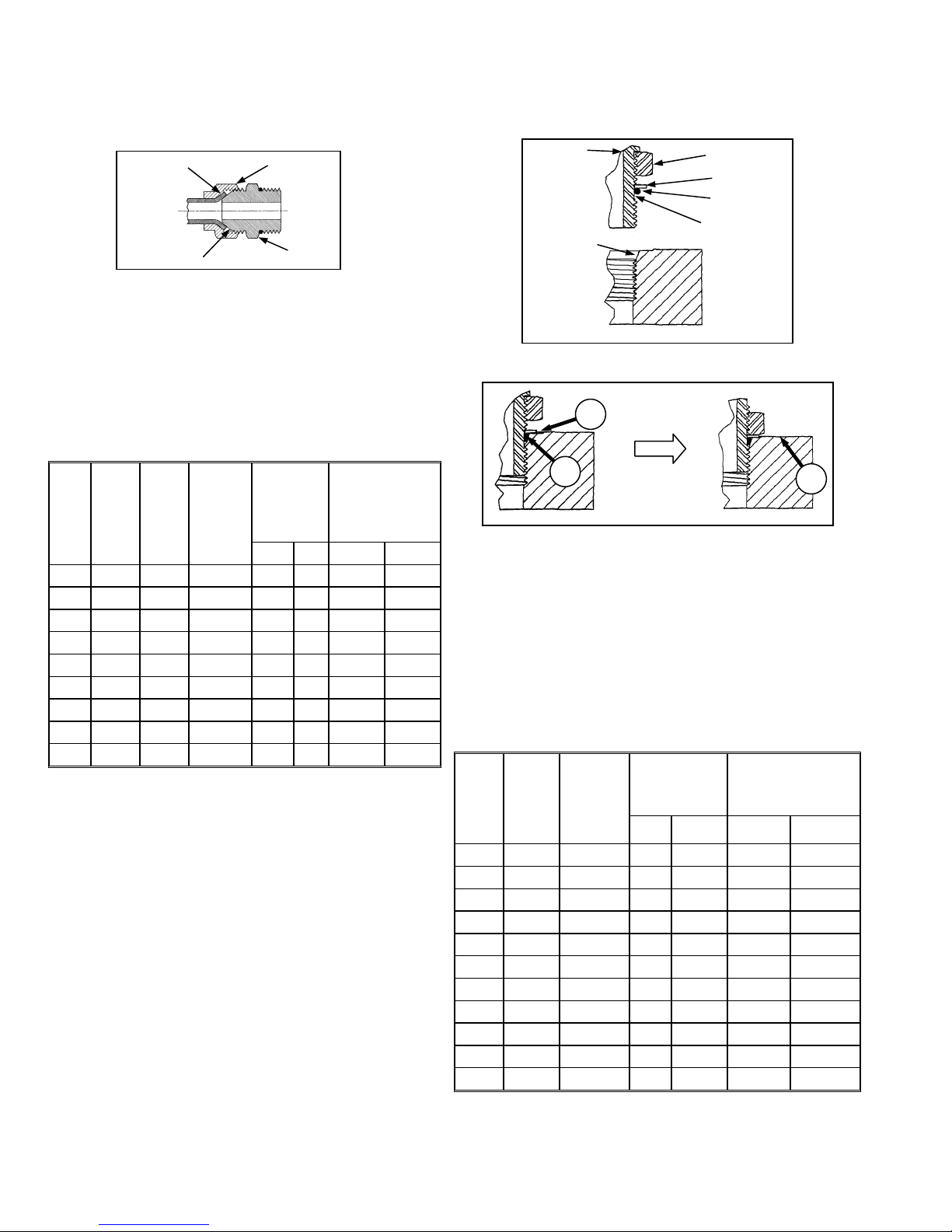
D. FLARE TYPE HYDRAULIC FITTINGS
FLARE
FLARESEAT
a. Check flare and flare seat for defects that might
cause leakage.
b. Align tube with fitting before tightening.
c. Lubricate connection and hand tighten swivel nut
until snug.
d. To prevent twisting the tube(s), use two wrenches.
Place one wrench on the connector body and with
the second, tighten the swivel nut to the torque
shown.
TUBE
SIZE
SAE
O.D.
NO.
(in.)
3 3/16
4 1/4
5 5/16
6 3/8
8 1/2
10 5/8
12 3/4
14 7/8
16 1
* The torque values shown are based on lubricated connections
as in reassembly.
THD
SIZE
(in.)
3/8
7/16
1/2
9/16
3/4
7/8
1-1/16
1-3/8
1-5/16
NUT
SIZE
ACROSS
FLATS
(in.)
7/16 6 8 1 1/6
9/16 9 12 1 1/6
5/8 12 16 1 1/6
11/16 18 24 1 1/6
7/8 34 46 1 1/6
1 46 62 1 1/6
1-1/4 75 102 3/4 1/8
1-3/8 90 122 3/4 1/8
1-1/2 105 142 3/4 1/8
NUT
BODY
RECOMMENDED
TORQUE
VALUE*
ft·lbf N·m Flats Turns
TURNS TO
TIGHTEN
(AFTER FINGER
TIGHTENING)
E. O-RING TYPE HYDRAULIC FITTINGS
FITTING
SEAT
a. Inspect O-ring and seat for dirt or obvious defects.
A
B
b. On angle fittings, back off the lock nut until washer
(A) bottoms out at top of groove (B) in fitting.
c. Hand tighten fitting until back up washer (A) or
washer face (if straight fitting) bottoms on part
face (C) and O-ring is seated.
d. Position angle fittings by unscrewing no more than
one turn.
e. Tighten straight fittings to torque shown.
f. Tighten angle fittings to torque shown in the
following table while holding body of fitting with a
wrench.
TORQUE
VALUE*
ft·lbf N·m Flats Turns
SAE
NO.
THD
SIZE
(in.)
NUT SIZE
ACROSS
FLATS
(in.)
LOCKNUT
WASHER
O-RING
GROOVE
C
RECOMMENDED
TURNS TO TIGHTEN
(AFTER FINGER
TIGHTENING)
Form 169242 Revision D
3 3/8 1/2 6 8 2 1/3
4 7/16 9/16 9 12 2 1/3
5 1/2 5/8 12 16 2 1/3
6 9/16 11/16 18 24 2 1/3
8 3/4 7/8 34 46 2 1/3
10 7/8 1 46 62 1-1/2 1/4
12 1-1/16 1-1/4 75 102 1 1/6
14 1-3/16 1-3/8 90 122 1 1/6
16 1-5/16 1-1/2 105 142 3/4 1/8
20 1-5/8 1-7/8 140 190 3/4 1/8
24 1-7/8 2-1/8 160 217 1/2 1/12
* The torque values shown are based on lubricated connections
as in reassembly.
6

ENGLISH/METRIC EQUIVALENTS
QUANTITY
FACTOR
UNIT NAME ABBR. UNIT NAME ABBR.
Area acres acres x 0.4047 = hectares ha
Flow US gallons per minute (gpm) x 3.7854 = liters per minute L/min
Force pounds force lbf x 4.4482 = Newtons N
INCH-POUND UNITS
Length
Power horsepower hp x 0.7457 = kilo watts kW
Pressure pounds per square inch psi
Torque
Temperature degrees Fahrenheit ˚F (˚F - 32) x 0.56 = Celsius ˚C
Velocity
Volume
Weight pounds lb x 0.4536 = kilograms kg
inch in. x 25.4 = millimeters mm
foot ft x 0.305 = meters m
x 6.8948 = kilopascals kPa
x .00689 = megapascals MPa
pound feet or foot pounds lbf·ft or ft·lbf x 1.3558 = newton meters N·m
pound inches or inch pounds lbf·in. or in·lbf x 0.1129 = newton meters N·m
feet per minute ft/min x 0.3048 = meters per minute m/min
feet per second ft/s x 0.3048 = meters per second m/s
miles per hour mph x 1.6063 = kilometers per hour km/h
US gallons US gal. x 3.7854 = liters L
ounces oz. x 29.5735 = milliliters ml
cubic inches in.3 x 16.3871 = cubic centimeters cm3 or cc
SI UNITS (METRIC)
DEFINITIONS
TERM DEFINITION
API
ASTM
Cab-Forward
CDM
DWA
Engine-Forward
ISC
N-DETENT
rpm
SAE
WCM
Windrower
Windrower Tractor
Form 169242 Revision D
American Petroleum Institute
American Society of Testing And Materials
Windrower operation with the Operator and cab facing in the direction of travel.
Cab Display Module
Double Windrow Attachment
Windrower operation with the Operator and engine facing in the direction of travel.
Integrated Speed Control
The slot opposite the neutral position on Operator’s console.
revolutions per minute
Society Of Automotive Engineers
Windrower Control Module
Windrower with header attached.
Power unit only. (Windrower without the header attached)
7
UNLOADING AND ASSEMBLY
STEP 1. UNLOAD CONTAINER
CAUTION
To avoid injury to bystanders from being
struck by machinery, do not allow persons to
stand in unloading area.
a. Move trailer into position and block trailer wheels.
b. Lower trailer storage stands.
c. Open container doors and remove all blocking.
d. Check container floor for nails or other
obstructions and remove if necessary.
e. Position platform or ramp at container opening.
STEP 2. MOVE TO ASSEMBLY
AREA
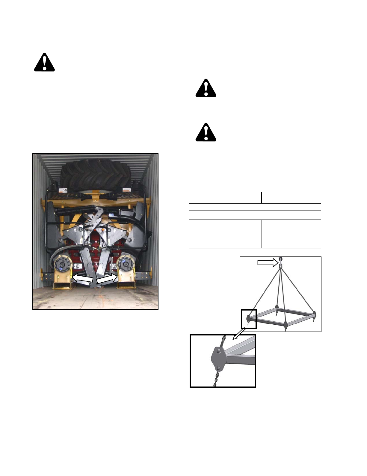
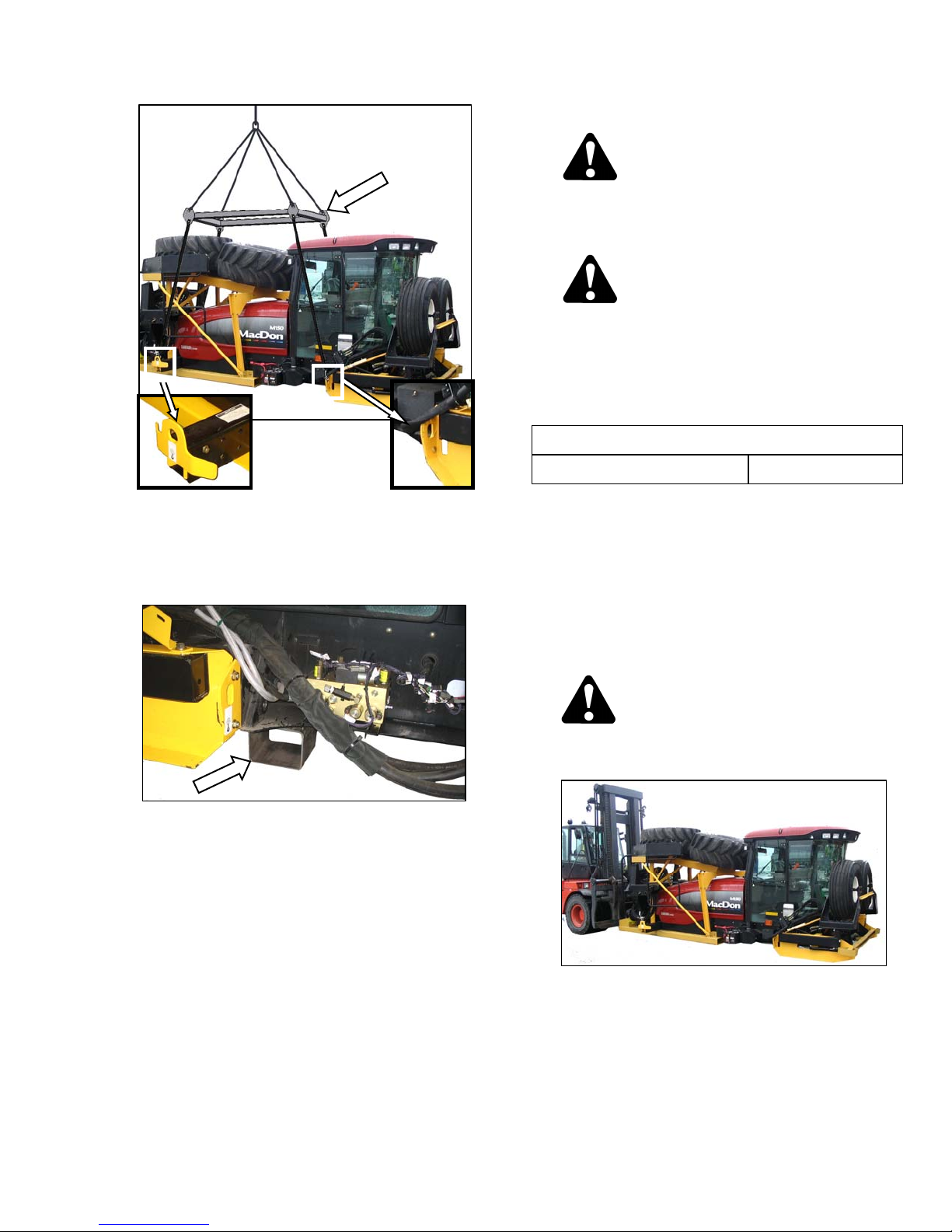
A. CRANE METHOD
CAUTION
To avoid injury to bystanders from being
struck by machinery, do not allow persons to
stand in unloading area.
CAUTION
Equipment used for unloading must meet or
exceed the requirements specified below.
Using inadequate equipment may result in
chain breakage, vehicle tipping or machine
damage.
LIFTING VEHICLE
Minimum Lifting Capacity 20,000 lb (9072 kg)
CHAIN
Type
Overhead Lifting
Quality (1/2 inch)
f. Attach chain/pull strap to slots in support channels
as shown.
g. Pull windrower from container onto platform.
Minimum Working Load 7100 lb (3221 kg)
a. Attach chains or cable to the four lift points on the
lifting frame (MacDon Part # 163871) and connect
loop ends to crane hook. Use cable or chain with
a minimum lifting capacity of 7100 lb (3221 kg).
(continued next page)
Form 169242 Revision D
8
UNLOADING AND ASSEMBLY
B. FORKLIFT METHOD
To avoid injury to bystanders from being
struck by machinery, do not allow persons to
stand in unloading area.
Equipment used for unloading must meet or
exceed the requirements specified below.
Using inadequate equipment may result in
chain breakage, vehicle tipping or machine
damage.
Minimum Lifting Capacity * 20,000 lb (9072 kg)
CAUTION
CAUTION
LIFTING VEHICLE
b. Attach lifting frame assembly (MacDon Part #
163871) to the four designated lift points on
windrower shipping frame.
c. Lift windrower off platform, and move to setup
area.
d. Lower assembly onto 5 - 6 inch (127 - 152 mm)
blocks as shown.
e. Remove chains from shipping frame.
f. Check for shipping damage and missing parts.
* At 48 inches (1220 mm) from back end of forks.
IMPORTANT
Forklifts are normally rated for a load
located 24 inches (610 mm) ahead of
back end of the forks.
To obtain the forklift capacity at 48
inches (1220 mm), check with your
forklift distributor.
WARNING
Be sure forks are secure before moving away
from load. Stand clear when lifting.
Form 169242 Revision D
a. Approach windrower from the hood end, and slide
forks underneath lifting framework.
b. Raise windrower off platform, and move to
assembly area.
(continued next page)
9
UNLOADING AND ASSEMBLY
c. Lower assembly onto 5 - 6 inch (127 - 152 mm)
blocks as shown.
d. Check for shipping damage and missing parts.
Form 169242 Revision D
10
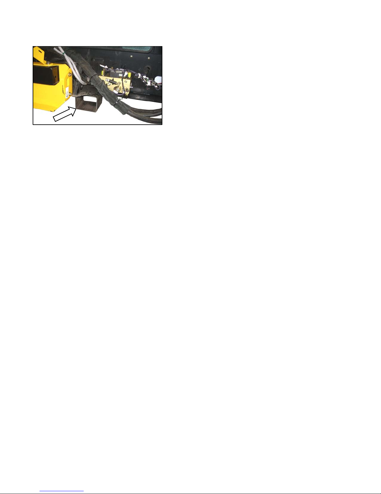
UNLOADING AND ASSEMBLY
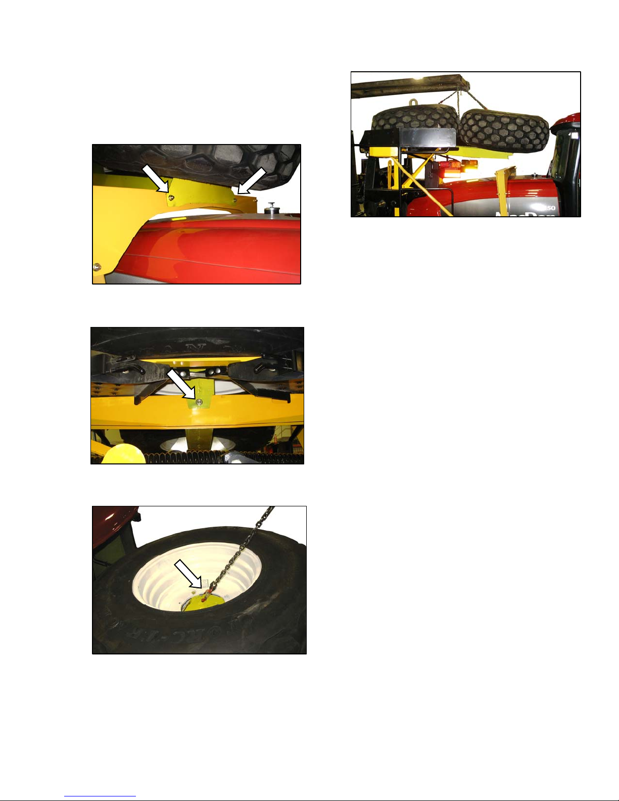
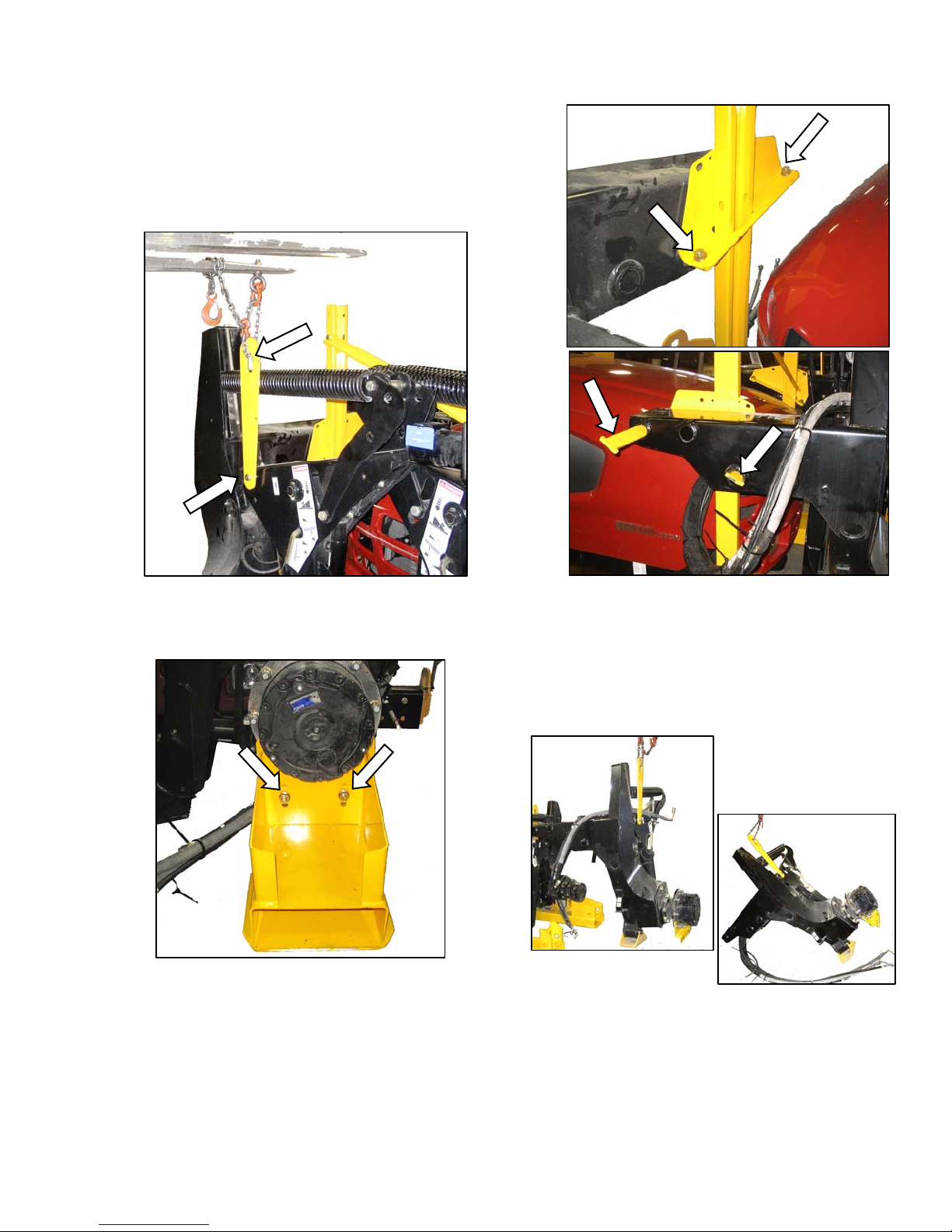
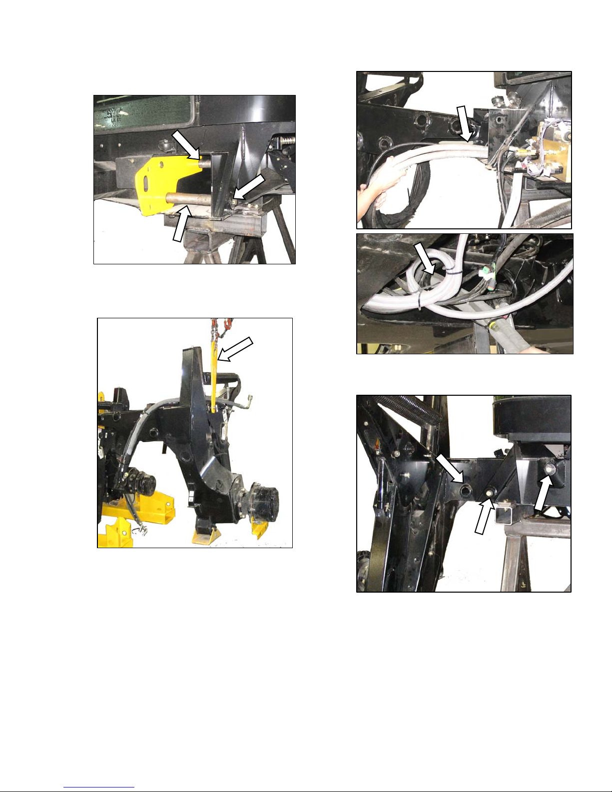
STEP 3. REMOVE WHEEL AND
STEP ASSEMBLY
a. Remove shipping wire and bolt securing hose
support to shipping frame, and remove hose
support.
b. Lay hose support off to the side.
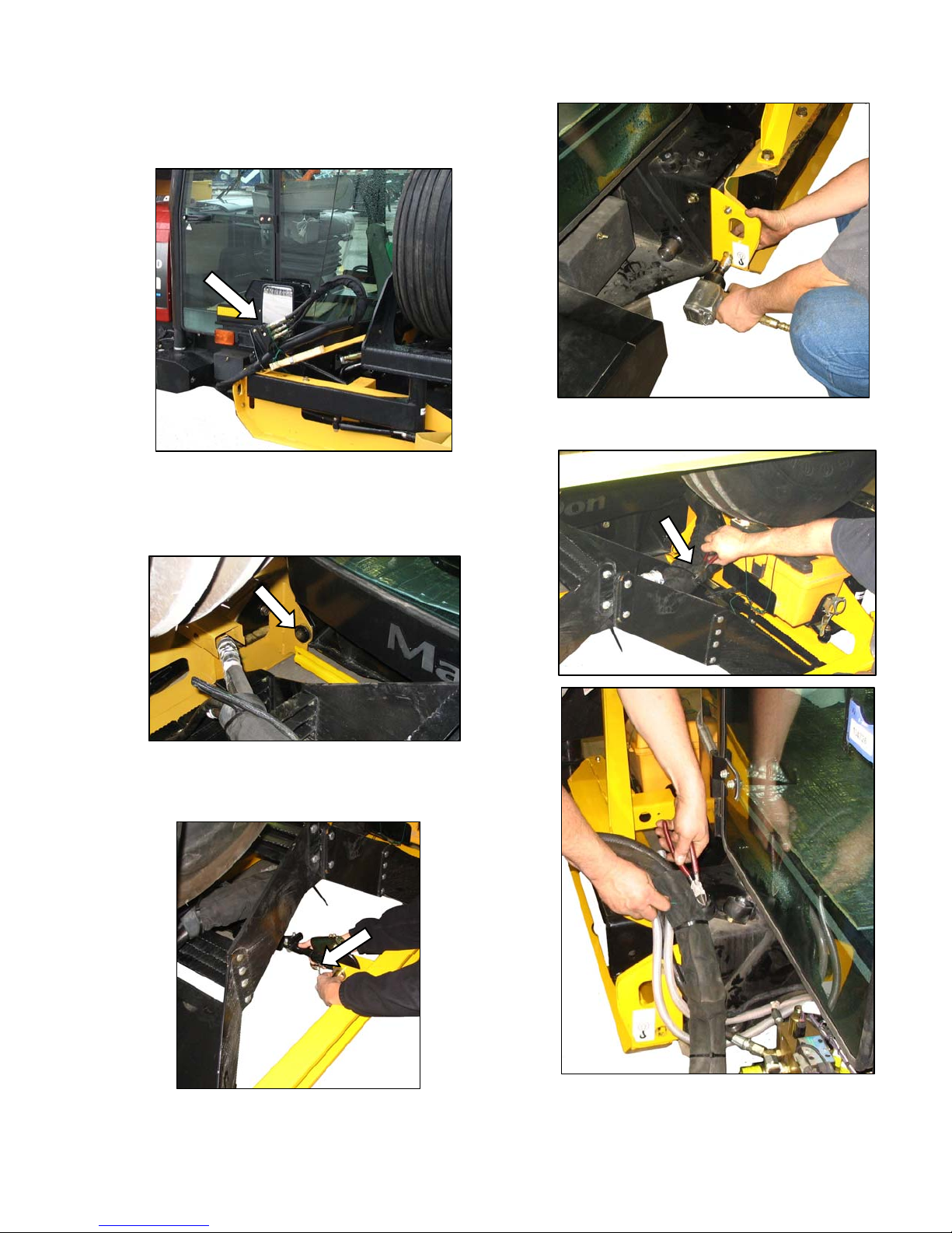
e. Remove the four (two per side) carriage bolts at
the rear of the wheel/step assembly.
c. Remove the two ¾ in. x 16.5 long bolts (one per
side) at front frame beam. Retain for
reinstallation.
f. Remove plastic cable tie and shipping wire
d. Remove the 1 inch (25.4 mm) pin at the center-
link.
Form 169242 Revision D
11
securing hose bundles to frame.
(continued next page)
UNLOADING AND ASSEMBLY
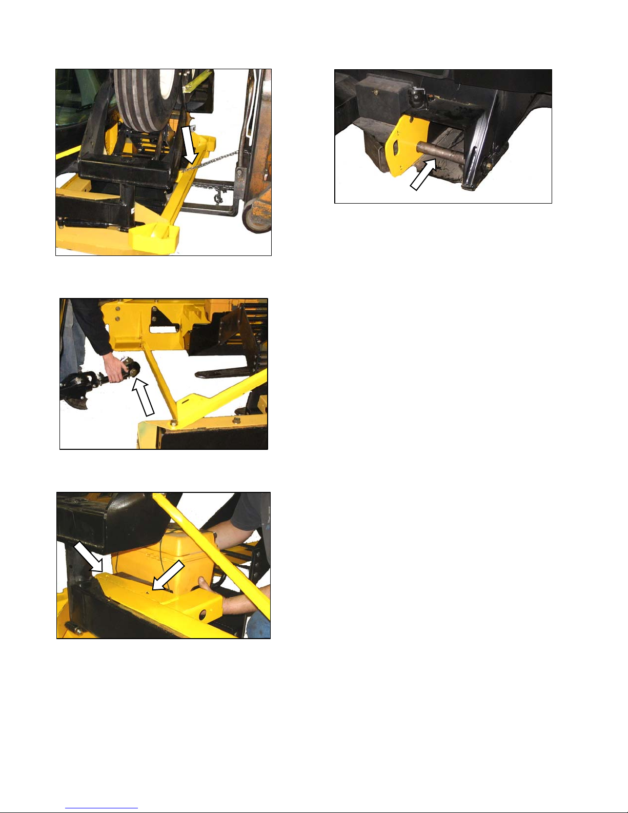
g. Attach a chain to wheel/step assembly, and pull
away from shipping assembly with lifting device.
j. Reinstall leg bolts, washers, and nuts to secure
the lifting plate onto the mainframe.
h. Lift center-link so that it clears wheel/step
assembly frame.
i. Remove bolts, and remove tool box and holder
from shipping frame. Loosely install bolts in
holder, and set aside for later installation.
Form 169242 Revision D
12
UNLOADING AND ASSEMBLY
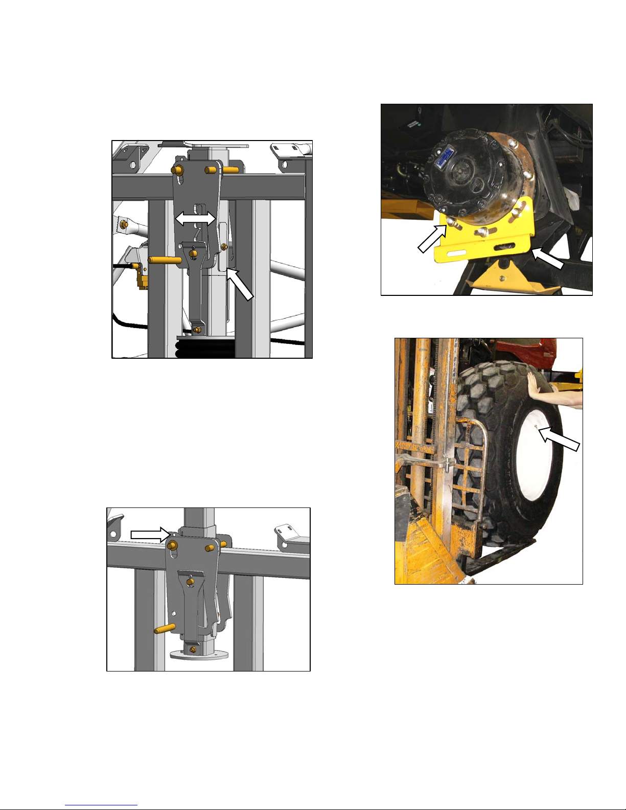
STEP 4. REMOVE DRIVE WHEELS
IMPORTANT
Remove the drive wheels as a pair from
above the hood.
a. Remove the two bolts at front cross member over
the hood.
d. Carefully lift wheels off frame.
IMPORTANT
Ensure that tire is guided away from
cab roof when lifting wheels to prevent
damage to the cab. Chain on forward
wheel should be snug and loose on the
aft wheel.
e. Set wheels aside for later installation.
b. Remove one bolt at rear of hood directly under
center of drive wheel.
c. Attach a lifting device to lift hooks located in the
center of each drive wheel.
Form 169242 Revision D
13
UNLOADING AND ASSEMBLY
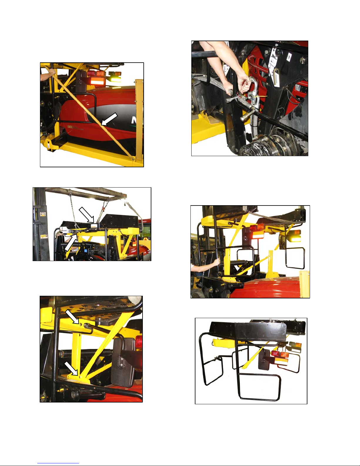
STEP 5. REMOVE PLATFORM /
LIGHT ASSEMBLY
a. Remove the two support tubes on either side of
hood.
d. Cut plastic cable ties, and move hose bundle clear
of platform.
NOTE
The M100 windrower is equipped with
only one platform.
b. To prevent paint damage, attach slings to platform
at locations shown, and to a lifting device with a
minimum lifting capacity of 5000 lb (2268 kg), and
a lift height of 13 feet (4 m).
e. Carefully lift platform/light assembly off frame until
rails clear windrower legs.
c. Remove two 5/8 in. x 5.0 bolts at top of vertical
support, and two bolts on bottom of support brace.
Form 169242 Revision D
f. Back away from windrower, and set assembly on
a level surface. Protect handrails with foam or
cardboard to prevent paint damage.
14
UNLOADING AND ASSEMBLY
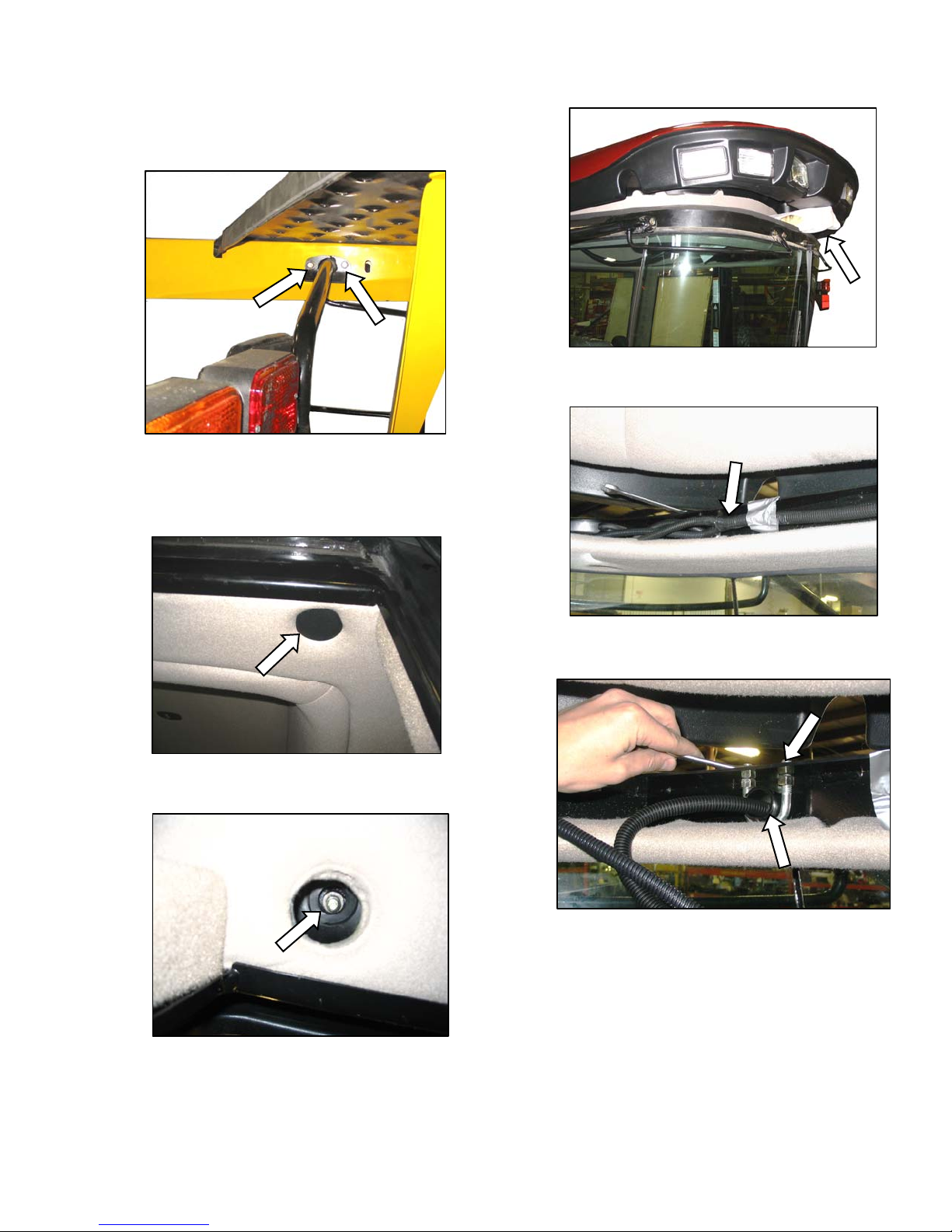
STEP 6. INSTALL LIGHT AND
MIRROR ASSEMBLIES
a. Remove two bolts securing mirror/light assemblies
to shipping stand, and remove assemblies.
b. The cab roof must be raised to install the light
assemblies. Proceed as follows:
3. Lift roof, and support with wooden block
covered with foam to prevent scuffing of roof.
c. Move existing harness in roof to gain access to
1. Remove plastic covers from six bolt locations
in roof.
2. Remove nuts and washers at these locations.
mirror/light support clamps. Loosen U-bolt.
d. Install mirror / light into U-bolt, and tighten nuts on
U-bolt so that support tube is securely fastened.
Tighten jam-nuts located under roof plate.
(continued next page)
Form 169242 Revision D
15
UNLOADING AND ASSEMBLY
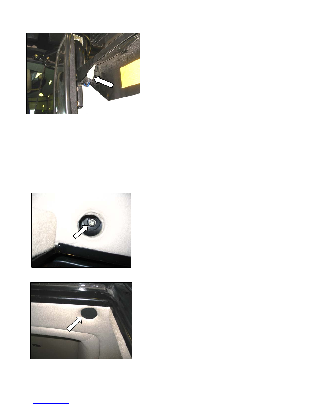
e. Thread wiring harness through support tube so
that connector is visible at light assembly.
f. Stuff foam into end of tube to help prevent dust
and noise from entering the cab.
g. Connect harness to connector at light.
h. Repeat steps c. to g. for opposite light assembly.
i. Remove roof support and lower ro of.
IMPORTANT
Ensure roof bolts clear grommets in
frame.
j. Reinstall washers and nuts at the six locations.
k. Reinstall plastic caps.
Form 169242 Revision D
16
UNLOADING AND ASSEMBLY
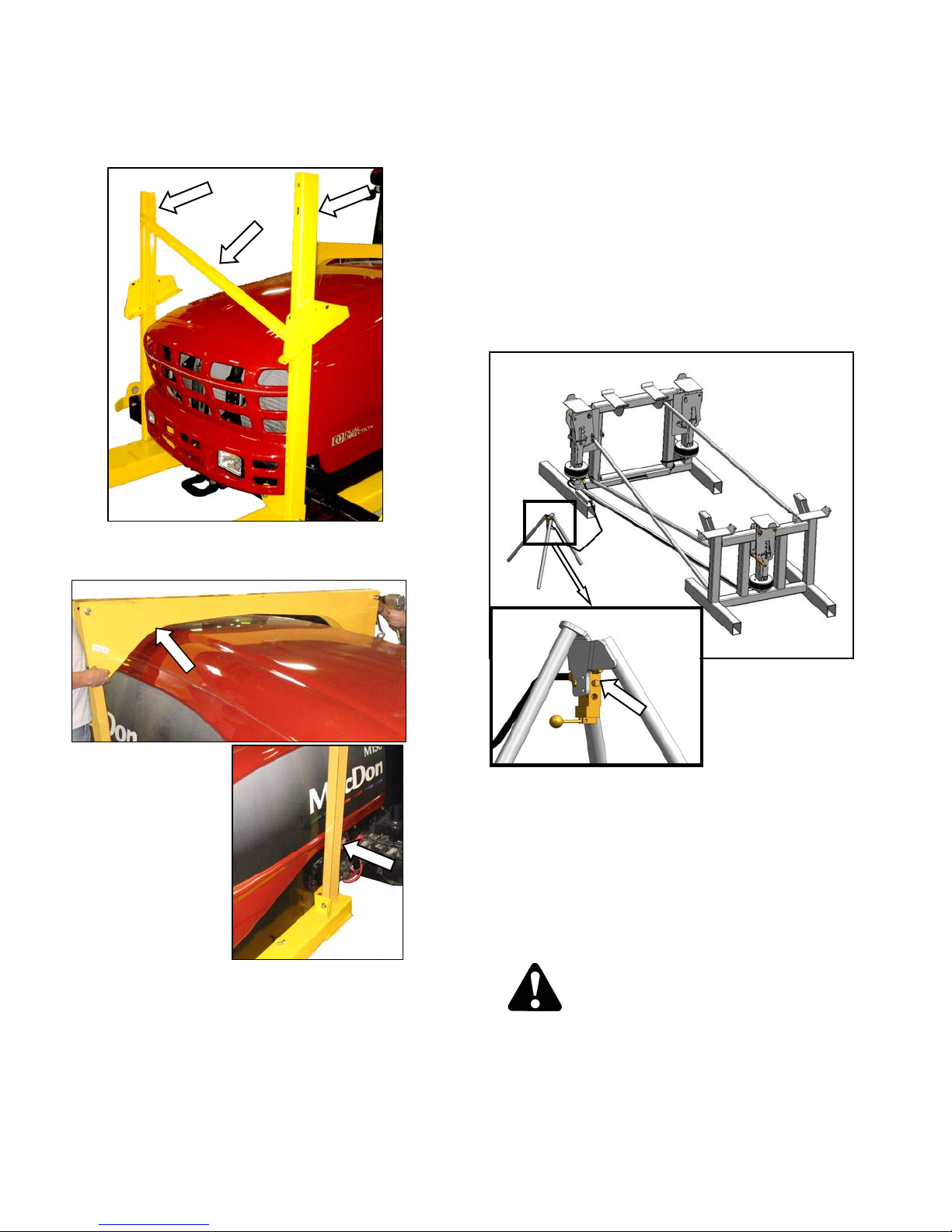
STEP 7. REMOVE LEG
ASSEMBLIES
a. Ensure that lift bar is attached to leg assembly as
shown, and that clevis pin is installed with head on
near side.
b. Attach chain to lifting bar on leg assembly, and
hook up to lifting device with a minimum lifting
capacity of 5000 lb (2268 kg).
c. Remove two bolts at lower support channel.
d. Remove two bolts near top of leg, and remove
bars from leg.
NOTE
Insert cardboard or foam between leg
assembly and hood to prevent damage
to hood.
e. Lift off leg assembly, and set securely on level
ground.
f. Repeat above steps for second leg assembly.
Form 169242 Revision D
17
UNLOADING AND ASSEMBLY
STEP 8. REMOVE WHEEL AND
PLATFORM SUPPORT
a. Remove cross brace, and the two upright supports
from frame.
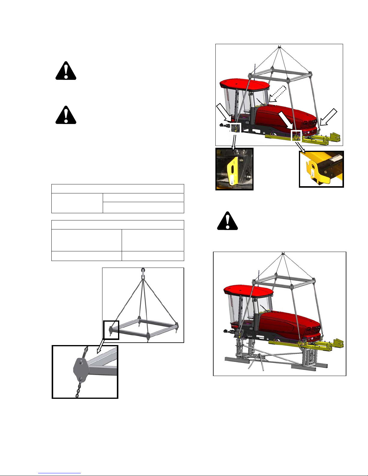
STEP 9. ASSEMBLE WINDROWER
SUPPORT STAND
Special stands for assembling the wi ndrow er are
available from the factory. If this stand is not
available, an equivalent support system can be
used.
The stand must be capable of holding a 20,000 lb
(9072 kg) load.
Assemble factory stand as follows:
a. Remove all shipping materials from stand.
FORWARD STAND
SUPPORT
b. Remove the cross member over the hood, and the
two uprights on either side.
REAR STAND
b. Arrange forward and rear stands on level ground,
so that attachment lugs on each stand face each
other.
c. Attach four support tubes to stands as shown wit h
hardware provided, and tighten.
d. Set up air control valve tripod. Remove plug on
valve, and install a 100 psi (689 kPa) air line.
e. The stand is now operational. Instructions for use
are given in the appropriate sections.
WARNING
• Use stand only as instructed in this
manual. Do not use stand for any other
purpose.
Form 169242 Revision D
• Do not pressurize air bags beyond 120 psi
(827 kPa).
18
UNLOADING AND ASSEMBLY
STEP 10. LIFT WINDROWER ONTO
STAND
CAUTION
To avoid injury to bystanders from being
struck by machinery, do not allow persons to
stand in unloading area.
CAUTION
Equipment used for unloading must meet or
exceed the requirements specified below.
Using inadequate equipment may result in
chain breakage, vehicle tipping or machine
damage.
A. CRANE METHOD
LIFTING VEHICLE
Crane
Minimum Lifting Capacity
20000 lb (9072 kg)
CHAIN
b. Attach the lifting frame to the four designated lift
points on windrower shipping frame as shown.
CAUTION
Type
Minimum Working Load
a. Attach four chains or cables to the four lift points
on the lifting frame (MacDon Part # 163871), and
connect loop ends to crane hook. Use cable or
chain with a minimum lifting capacity of 7100 lb
(3221 kg).
Overhead Lifting
Quality (1/2 inch)
7100 lb (3221 kg)
Stand clear when lifting, as machine may
swing.
c. Lift windrower onto stand.
d. Remove chains from shipping frame, and set
lifting frame assembly clear of work area.
Form 169242 Revision D
19
UNLOADING AND ASSEMBLY
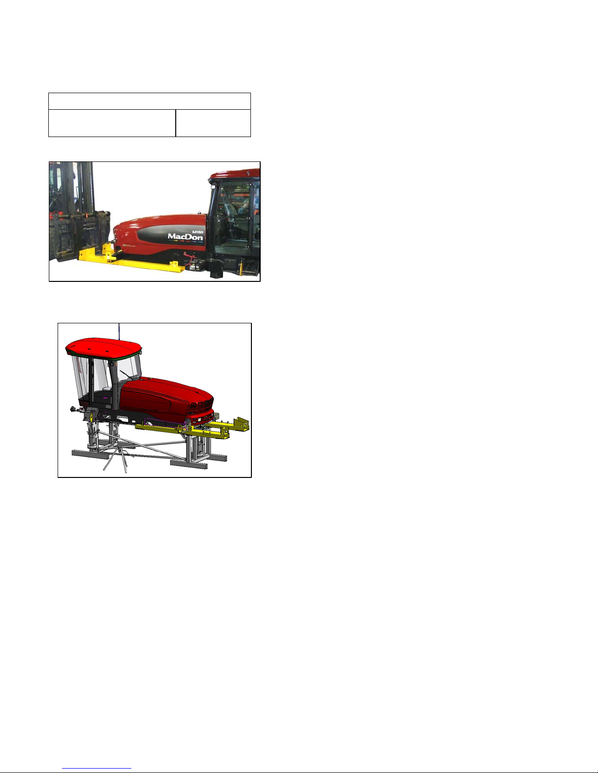
B. FORKLIFT METHOD
LIFTING VEHICLE
Minimum Lifting Capacity *
* At 48 inches (1220 mm) from back end of forks.
a. Approach windrower from aft end, and slide forks
fully into shipping support channels.
20,000 lb
(9072 kg)
b. Raise windrower and place onto stand.
c. Back away forklift.
Form 169242 Revision D
20
UNLOADING AND ASSEMBLY
STEP 11. INSTALL LEGS
a. Remove front leg bolts and pins, and set aside for
reinstallation. Remove carriage bolt, and remove
lifting plate.
b. Attach front leg to lifting device with lifting bar.
c. Position leg at frame.
d. Feed hydraulic hose bundle into frame, and
through hole at center of frame.
e. Insert leg into frame, and line up holes in frame
and leg at the first position (widest tread with one
exposed hole).
f. Insert pins and secure with ¾ in. x 16.5 long bolts,
washers, and nuts. Torque to 100 ft·lbf (136 N·m).
g. Repeat above steps for other leg.
(continued next page)
Form 169242 Revision D
21

UNLOADING AND ASSEMBLY
h. Slightly lift th e header lift arms with lifting device,
and remove lifting bars from legs. Relocat e spring
locking pins to front of lift arms.
Form 169242 Revision D
22
UNLOADING AND ASSEMBLY
STEP 12. INSTALL FRONT
WHEELS
a. If factory stand is being used, proceed as follows,
otherwise proceed to step b:
4. Release pressure so that locks support we ight
of windrower.
b. Remove shipping supports on drive wheel hubs,
and remove wheel lug nuts.
1. Ensure that the three (one at rear, two at
front) lift locks are activated on lift mechanism.
NOTE
Lock is activated when keeper is
vertical, and latch is free to move back
and forth.
2. Pressurize air bag system (100 psi (689 kPa)
air pressure required), and raise windrower to
maximum height [approximately 7 inches (178
mm)] above stand.
3. Verify that all three locks are engaged, before
to proceeding to next step.
NOTE
c. Position wheel against hub so that that air valves
are on outside, and tire tread points forward.
For "Turf” tires (diamond tread), be sure arrow on
sidewall points in forward rotation.
d. Lift wheel on hub with lifting device. Lower lifting
device.
e. Rotate wheel to align holes with studs, and push
wheel onto studs.
(continued next page)
Lock is engaged when witness hole
above pin is exposed.
Form 169242 Revision D
23
UNLOADING AND ASSEMBLY
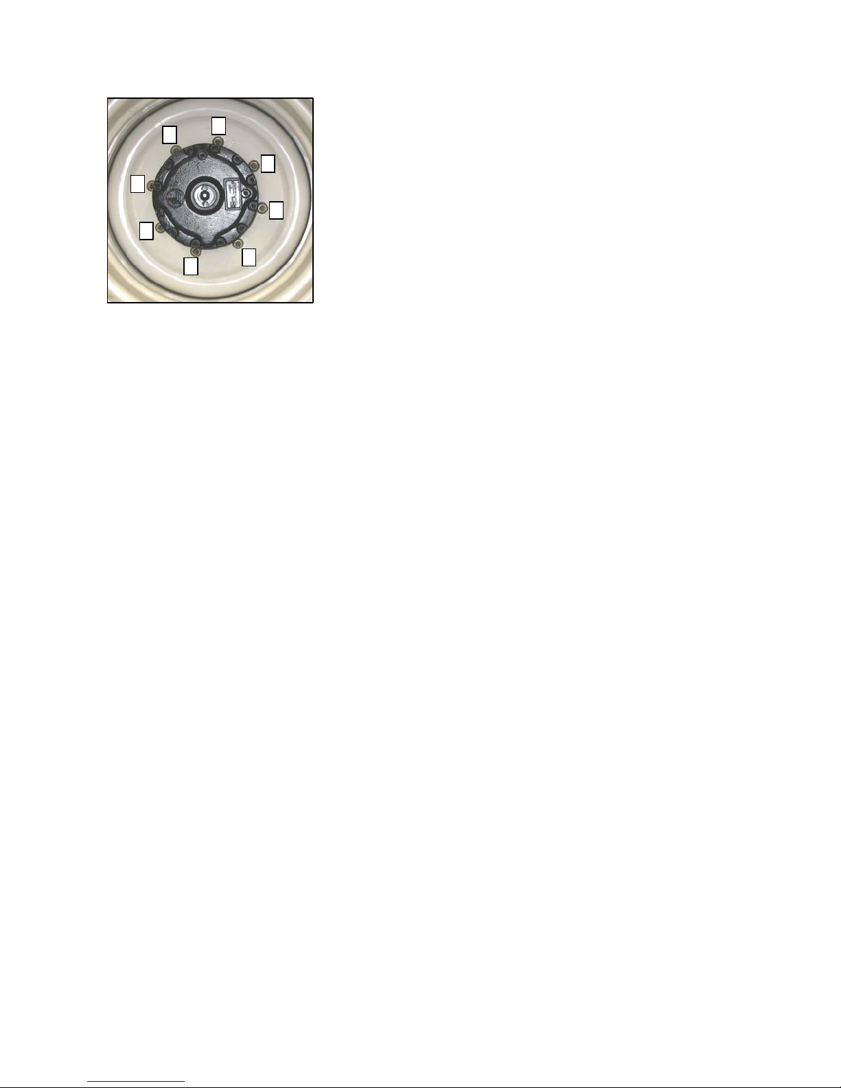
6
1
4
3
7
8
5
2
f. Install wheel nuts, and tighten to 220 ft·lbf (300
N·m) using the tightening sequence as shown.
NOTE
To avoid damage to wheel disks, do not
over-tighten wheel nuts.
g. Repeat sequence three times.
Form 169242 Revision D
24
UNLOADING AND ASSEMBLY
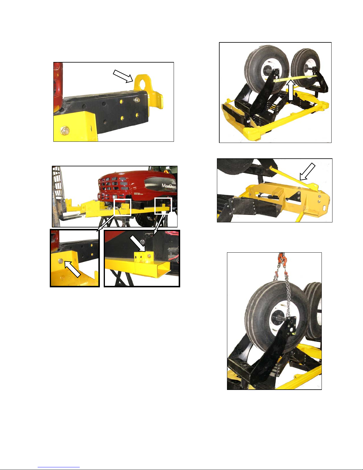
STEP 13. INSTALL CASTER
WHEELS
a. Remove the two guide plates from ends of walking
beam.
b. Support shipping frame channel, and remove bolts
attaching shipping frame to walking beam and
mainframe side rail. Remove shipping frame.
NOTE
d. Remove tie bar between the two caster wheels.
e. Remove the two braces from caster wheels and
frame. Retain bolts for attaching caster to walking
beam.
Shipping frame does not need to be
removed if air bag lifting stand is used.
Ensure bolts are removed prior to
moving windrower off stand.
c. Repeat above for opposite shipping frame
channel.
Form 169242 Revision D
f. Attach a chain to RH caster, and support caster
with lifting device.
(continued next page)
25

UNLOADING AND ASSEMBLY
g. Remove five remaining bolts securing caster to
shipping frame. Retain bolts for attaching caster
to walking beam.
CAUTION
Stand clear when lifting, as caster may
swing.
k. Tighten bolts as follows:
1. Snug up the two bolts underneath beam.
2. Tighten the four back bolts to 330 ft·lbf (447
N·m).
3. Tighten bolts underneath beam to 330 ft·lbf
(447 N·m).
l. Repeat above steps g. to k. for LH ca ster.
m. Re-torque bolts at 5, and 10 hours of operation.
h. Lift caster assembly off shipping frame, and
position at end of walking beam.
i. Insert RH caster extension into walking beam, and
position for desired tread.
j. Install six ¾ in. bolts and hardened washers into
walking beam and caster beam. Use longer bolts
through anti-shimmy bracket.
Form 169242 Revision D
26
UNLOADING AND ASSEMBLY
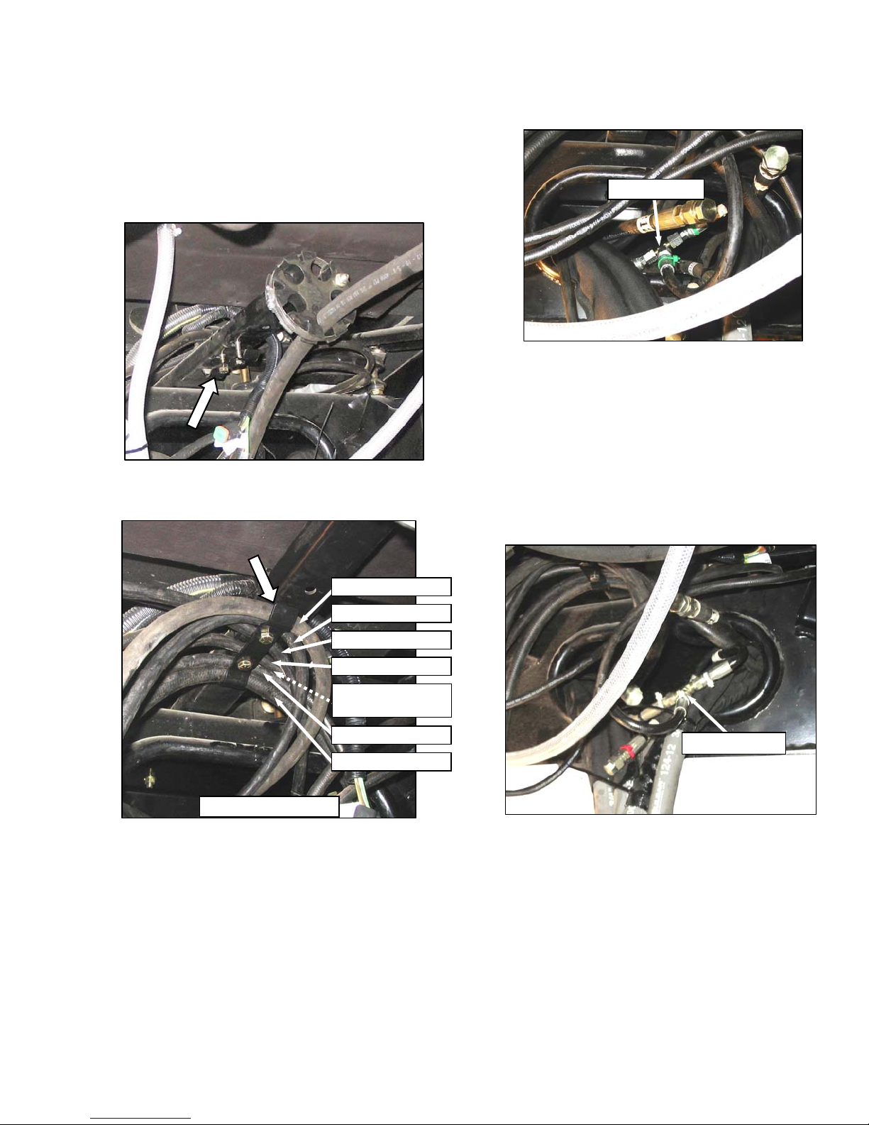
STEP 14. INSTALL HYDRAULICS
A. M150, M200
a. The hydraulic hoses under the cab may require
proper placement under the existing clip. If
necessary, proceed as follows:
b. Connect hoses as follows, using coloured plastic
cable ties as a guide.
111327 GREEN
1. Locate two hoses 111327 (green ties) in
frame opening, and existing tee fitting (green
tie).
2. Remove caps on green lines and tee, and
make connections. Tighten fittings.
NOTE
1. Locate hose clip under the cab, and remove
clip.
111557 YELLOW
111323 BLUE
111323 ORANGE
111324 WHITE ‘T’
111324 (M200 ONLY)
(NOT SHOWN)
111327 GREEN ‘T’
111328 WHITE
VIEW FORWARD
2. Position hose 111323 (orange tie) and hose
111324 with tee (white tie), as shown under
the center of the clip, and loosely install two
bolts and nuts. Part numbers are located on
hoses. (If M200, place another hose 1132A
with tee under clip)
3. Position remaining hoses under clip as shown,
and tighten bolts.
Remove caps on tee last to minimize oil
loss.
3. Position hoses into frame.
111324 WHITE ‘T’
4. Locate two hoses (white ties) inside frame,
and hose 111324 with tee (white tie).
5. Remove caps, make connections, and tighten
fittings.
6. Push hoses into frame.
(continued next page)
Form 169242 Revision D
27
 Loading...