

MacDon M150, M200 Assembly Instructions Manual

M150, M200 Self-Propelled Windrower
Published: September, 2010
UNLOADING AND ASSEMBLY
INSTRUCTIONS
NORTH AMERICAN SHIPMENTS
for
Form 169018 Revision C
MACDON SELF PROPELLED AUGER HEADER
Form # 169018 Revision C
MACDON SELF-PROPELLED WINDROWER

INTRODUCTION
This instructional manual describes the unloading, set-up and pre-delivery requ ireme nts for t he Ma cDon M150
and M200 Self-Propelled Windrowers.
Use the Table of Contents to guide you to specific areas.
Retain this instruction for future reference.
CAREFULLY READ ALL THE MATERIAL PROVIDED BEFORE ATTEMPTING TO UNLOAD, ASSEMBLE, OR
USE THE MACHINE.
Form 169018 1 Revision C

TABLE OF CONTENTS
INTRODUCTION ........................................................................................................................................................ 1
GENERAL SAFETY ................................................................................................................................................... 3
RECOMMENDED TORQUES ................................................................................................................................... 5
A. GENERAL ............................................................................................................................................... 5
B. SAE BOLTS ............................................................................................................................................ 5
C. METRIC BOLTS ..................................................................................................................................... 5
D. FLARE TYPE HYDRAULIC FITTINGS .................................................................................................. 6
E. O-RING TYPE HYDRAULIC FITTINGS ................................................................................................. 6
ENGLISH/METRIC EQUIVALENTS .......................................................................................................................... 7
DEFINITIONS ............................................................................................................................................................. 7
STEP 1. UNLOAD WINDROWER .......................................................................................................................... 8
A. TWO FORKLIFT METHOD .................................................................................................................... 8
B. SINGLE FORKLIFT METHOD ............................................................................................................... 9
I. METHOD 1 ........................................................................................................................................ 9
II. METHOD 2 ........................................................................................................................................ 9
STEP 2. REPOSITION RH LEG ........................................................................................................................... 11
STEP 3. INSTALL FRONT WHEELS ................................................................................................................... 12
STEP 4. REPOSITION CASTER WHEELS ......................................................................................................... 12
STEP 5. INSTALL STEPS .................................................................................................................................... 13
STEP 6. INSTALL CENTER-LINK ........................................................................................................................ 14
STEP 7. INSTALL BATTERIES ............................................................................................................................ 14
STEP 8. INSTALL AM/FM RADIO ........................................................................................................................ 16
STEP 9. INSTALL SLOW MOVING VEHICLE (SMV) SIGN ................................................................................ 17
STEP 10. ATTACH HEADER ................................................................................................................................. 18
A. HEADER ATTACHMENT - D SERIES ................................................................................................. 18
B. HEADER ATTACHMENT - A SERIES ................................................................................................. 24
C. HEADER ATTACHMENT - R SERIES ................................................................................................. 28
STEP 11. LUBRICATE MACHINE .......................................................................................................................... 32
STEP 12. PROGRAM CAB DISPLAY MODULE (CDM) ........................................................................................ 34
STEP 13. PERFORM PRE-DELIVERY CHECKS .................................................................................................. 40
A. FINAL DRIVE LUBRICANT LEVEL ...................................................................................................... 40
B. TIRE PRESSURES AND BALLAST REQUIREMENTS ....................................................................... 40
I. Tire Pressures ................................................................................................................................. 40
II. Ballast Requirements ...................................................................................................................... 40
C. ENGINE COOLANT ............................................................................................................................. 41
D. AIR CLEANER ...................................................................................................................................... 42
E. HYDRAULIC OIL LEVEL ...................................................................................................................... 42
F. FUEL SEPARATOR ............................................................................................................................. 43
G. GEAR BOX LUBRICANT LEVEL ......................................................................................................... 43
H. A/C COMPRESSOR BELT ................................................................................................................... 43
I. PERFORM SAFETY SYSTEM CHECKS ............................................................................................. 44
J. OPERATIONAL CHECKS .................................................................................................................... 45
I. ENGINE WARNING LIGHTS .......................................................................................................... 45
II. START ENGINE .............................................................................................................................. 45
III. GAUGES AND CDM DISPLAY ....................................................................................................... 47
IV. ELECTRICAL .................................................................................................................................. 47
V. ENGINE SPEED ............................................................................................................................. 47
VI. OPERATOR’S PRESENCE SYSTEM CHECKS ............................................................................ 47
VII. EXTERIOR LIGHTS ........................................................................................................................ 48
VIII. BEACON (If Installed) ..................................................................................................................... 49
IX. HORN .............................................................................................................................................. 49
X. INTERIOR LIGHTS ......................................................................................................................... 50
XI. A/C AND HEATER .......................................................................................................................... 50
K. MANUALS ............................................................................................................................................ 50
L. CAB INTERIOR .................................................................................................................................... 50
Form 169018 2 Revision C

GENERAL SAFETY
CAUTION
The following are general farm safety
precautions that should be part of your
operating procedure for all types of machinery .
• Protect yourself.
• When assembling, operating and servicing
machinery, wear all the protective clothing
and personal safety devices that COULD
be necessary for the job at hand. Don't
take chances.
• You may need:
o a hard hat.
o protective shoes with slip resistant
soles.
o protective glasses or goggles.
o heavy gloves.
o wet weather gear.
o respirator or filter mask.
• Provide a first-aid kit for use in case of
emergencies.
• Keep a fire extinguisher on the machine.
Be sure the extinguisher is properly
maintained and be familiar with its proper
use.
• Keep young children away from machinery
at all times.
• Be aware that accidents often happen
when the operator is tired or in a hurry to
get finished. Take the time to consider the
safest way. Never ignore warning signs of
fatigue.
• Wear close-fitting clothing
and cover long hair. Never
wear dangling items such
as scarves or bracelets.
• Keep hands, feet, clothing
and hair away from
moving parts. Never
attempt to clear
obstructions or objects from a machine
while the engine is running.
A
B
o hearing protection. Be aware that
prolonged exposure to loud noise can
cause impairment or loss of hearing.
Wearing a suitable hearing protective
device such as ear muffs (A) or ear
plugs (B) protects against
objectionable or loud noises.
Form 169018 3 Revision C
• Keep all shields in place. Never alter or
remove safety equipment. Make sure
driveline guards can rotate independently
of the shaft and can telescope freely.
• Use only service and repair parts made or
approved by the equipment manufacturer.
Substituted parts may not meet strength,
design, or safety requirements.

• Do not modify the machine. Unauthorized
modifications may impair the function
and/or safety and affect machine life.
• Stop engine, and remove key from ignition
before leaving operator's seat for any
reason. A child or even a pet could engage
an idling machine.
• Keep the area used for servicing
machinery clean and dry. Wet or oily floors
are slippery. Wet spots can be dangerous
when working with electrical equipment.
Be sure all electrical outlets and tools are
properly grounded.
• Use adequate light for the job at hand.
• Keep machinery clean. Do not allow oil or
grease to accumulate on service platforms,
ladders or controls. Clean machines before
storage.
• Never use gasoline, naphtha or any volatile
material for cleaning purposes. These
materials may be toxic and/or flammable.
• When storing machinery, cover sharp or
extending components to prevent injury
from accidental contact.
Form 169018 4 Revision C

RECOMMENDED TORQUES
A. GENERAL
The tables shown below give correct torque
values for various bolts and capscrews.
• Tighten all bolts to the torques specified in
chart unless otherwise noted throughout this
manual.
• Check tightness of bolts periodically, using
bolt torque chart as a guide.
• Replace hardware with the same strength
bolt.
• Torque figures are valid for non-greased or
non-oiled threads and heads unless otherwise
specified. Do not grease or oil bolts or
capscrews unless specified in this manual.
• When using locking elements, increase torque
values by 5%.
B. SAE BOLTS
NC BOLT TORQUE *
BOLT
DIA. "A"
in.
1/4 9 12 11 15
5/16 18 24 25
3/8 32 43 41
7/16 50 68 70 95
1/2 75 102 105 142
9/16 110 149 149 202
5/8 150 203 200 271
3/4
7/8 420 569 600 813
1 640 867 890 1205
* Torque categories for bolts and capscrews are identified by their
head markings.
SAE 5 SAE 8
ft·lbf N·m ft·lbf N·m
34
56
265 359
365 495
C. METRIC BOLTS
NC BOLT TORQUE *
BOLT
DIA. "A"
M3 0.4 0.5 1.3 1.8
M4 2.2 3 3.3 4.5
M5 4 6 7 9
M6 7 10 11 15
M8 18 25 26 35
M10 37 50 52 70
M12 66 90 92 125
M14 103 140 148 200
M16 166 225 229 310
M20 321 435 450 610
M24 553 750 774 1050
M30 1103 1495 1550 2100
M36 1917 2600 2710 3675
* Torque categories for bolts and capscrews are identified by their
head markings.
8.8 10.9
ft·lbf N·m ft·lbf N·m
SAE-5 SAE-8
Form 169018 5 Revision C
R
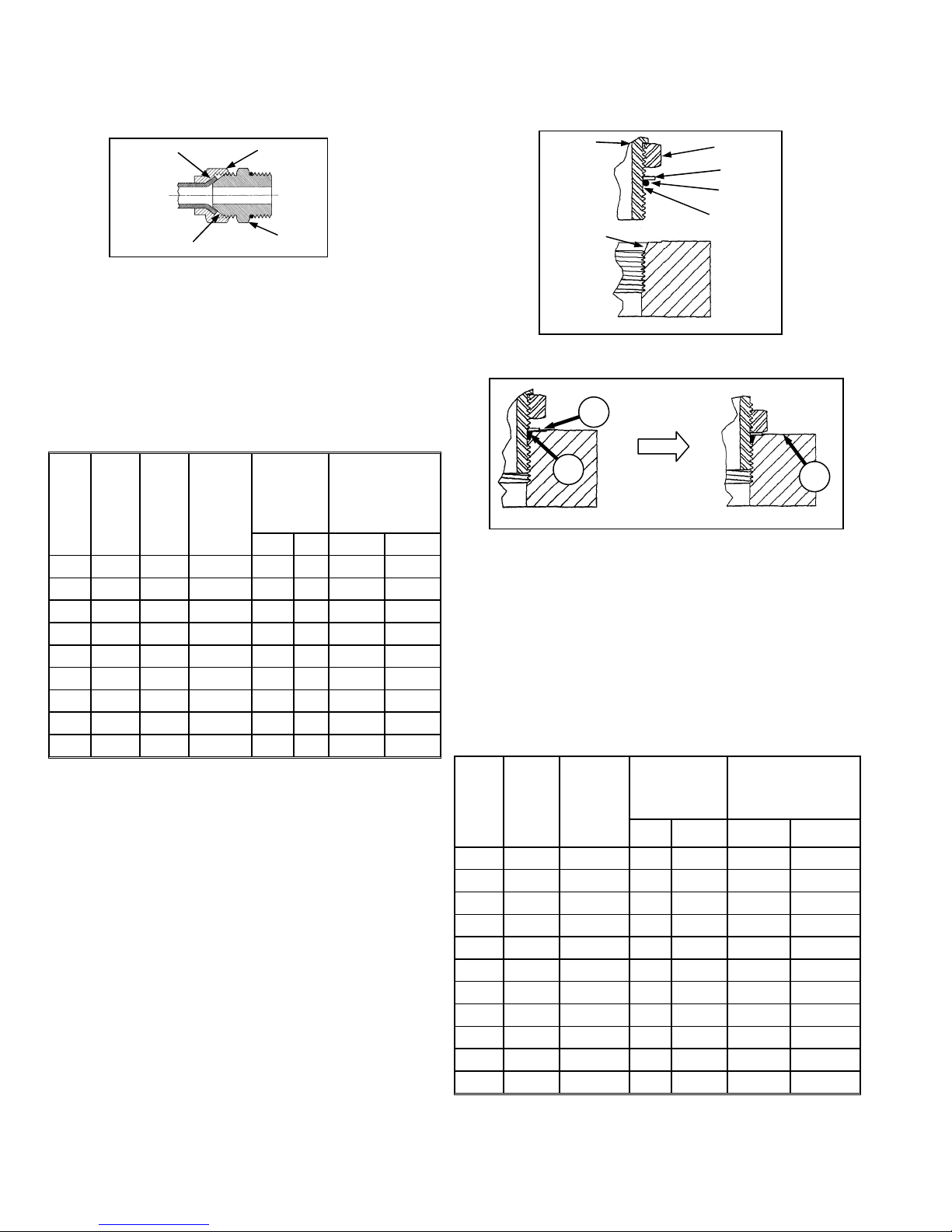
D. FLARE TYPE HYDRAULIC FITTINGS
FLARE
FLARESEAT
a. Check flare and flare seat for defects that might
cause leakage.
b. Align tube with fitting before tightening.
c. Lubricate connection and hand tighten swivel nut
until snug.
d. To prevent twisting the tube(s), use two wrenches.
Place one wrench on the connector body and with
the second tighten the swivel nut to the torque
shown.
TUBE
SIZE
SAE
O.D.
NO.
(in.)
3 3/16
4 1/4
5 5/16
6 3/8
8 1/2
10 5/8
12 3/4
14 7/8
16 1
* The torque values shown are based on lubricated connections
as in reassembly.
THD
SIZE
(in.)
3/8
7/16
1/2
9/16
3/4
7/8
1-1/16
1-3/8
1-5/16
NUT
SIZE
ACROSS
FLATS
(in.)
7/16 6 8 1 1/6
9/16 9 12 1 1/6
5/8 12 16 1 1/6
11/16 18 24 1 1/6
7/8 34 46 1 1/6
1-1/4 75 102 3/4 1/8
1-3/8 90 122 3/4 1/8
1-1/2 105 142 3/4 1/8
NUT
BODY
RECOMMENDED
TORQUE
VALUE*
ft·lbf N·m Flats Turns
1 46 62 1 1/6
TURNS TO
TIGHTEN
(AFTER FINGER
TIGHTENING)
E. O-RING TYPE HYDRAULIC FITTINGS
FITTING
SEAT
a. Inspect O-ring and seat for dirt or obvious defects.
A
B
b. On angle fittings, back off the lock nut until washer
(A) bottoms out at top of groove (B) in fitting.
c. Hand tighten fitting until back up washer (A) or
washer face (if straight fitting) bottoms on part
face (C) and O-ring is seated.
d. Position angle fittings by unscrewing no more than
one turn.
e. Tighten straight fittings to torque shown.
f. Tighten angle fittings to torque shown in the
following table while holding body of fitting with a
wrench.
TORQUE
VALUE*
ft·lbf N·m Flats Turns
SAE
NO.
THD
SIZE
(in.)
NUT SIZE
ACROSS
FLATS
(in.)
LOCKNUT
WASHE
O-RING
GROOVE
C
RECOMMENDED
TURNS TO TIGHTEN
(AFTER FINGER
TIGHTENING)
Form 169018 6 Revision C
3 3/8 1/2 6 8 2 1/3
4 7/16 9/16 9 12 2 1/3
5 1/2 5/8 12 16 2 1/3
6 9/16 11/16 18 24 2 1/3
8 3/4 7/8 34 46 2 1/3
10 7/8 1 46 62 1-1/2 1/4
12 1-1/16 1-1/4 75 102 1 1/6
14 1-3/16 1-3/8 90 122 1 1/6
16 1-5/16 1-1/2 105 142 3/4 1/8
20 1-5/8 1-7/8 140 190 3/4 1/8
24 1-7/8 2-1/8 160 217 1/2 1/12
* The torque values shown are based on lubricated connections
as in reassembly.

ENGLISH/METRIC EQUIVALENTS
QUANTITY
FACTOR
UNIT NAME ABBR. UNIT NAME ABBR.
Area acres acres x 0.4047 = hectares ha
Flow US gallons per minute (gpm) x 3.7854 = liters per minute L/min
Force pounds force lbf x 4.4482 = Newtons N
INCH-POUND UNITS
Length
Power horsepower hp x 0.7457 = kilowatts kW
Pressure pounds per square inch psi
Torque
Temperature degrees Fahrenheit ˚F (˚F - 32) x 0.56 = Celsius ˚C
Velocity
Volume
Weight pounds lb x 0.4536 = kilograms kg
inch in. x 25.4 = millimeters mm
foot ft x 0.305 = meters m
x 6.8948 = kilopascals kPa
x .00689 = megapascals MPa
pound feet or foot pounds lbf·ft or ft·lbf x 1.3558 = newton meters N·m
pound inches or inch pounds lbf·in. or in·lbf x 0.1129 = newton meters N·m
feet per minute ft/min x 0.3048 = meters per minute m/min
feet per second ft/s x 0.3048 = meters per second m/s
miles per hour mph x 1.6063 = kilometers per hour km/h
US gallons US gal. x 3.7854 = liters L
ounces oz. x 29.5735 = milliliters ml
cubic inches in.3 x 16.3871 = cubic centimeters cm3 or cc
SI UNITS (METRIC)
DEFINITIONS
TERM DEFINITION
API
ASTM American Society of Testing And Materials
Cab-Forward
CDM Cab Display Module
DWA
Engine-Forward Windrower operation with the operator and engine facing in the direction of travel.
ISC
N-DETENT The slot opposite the neutral position on Operator’s console.
rpm
SAE Society Of Automotive Engineers
WCM
Windrower Windrower with header attached.
Windrower Tractor
American Petroleum Institute
Windrower operation with the operator and cab facing in the direction of travel.
Double Windrow Attachment
Integrated Speed Control
revolutions per minute
Windrower Control Module
Power unit only. (Windrower without the header attached)
Form 169018 7 Revision C
UNLOADING AND ASSEMBLY
STEP 1. UNLOAD WINDROWER
CAUTION
To avoid injury to bystanders from being
struck by machinery, do not allow persons to
stand in unloading area.
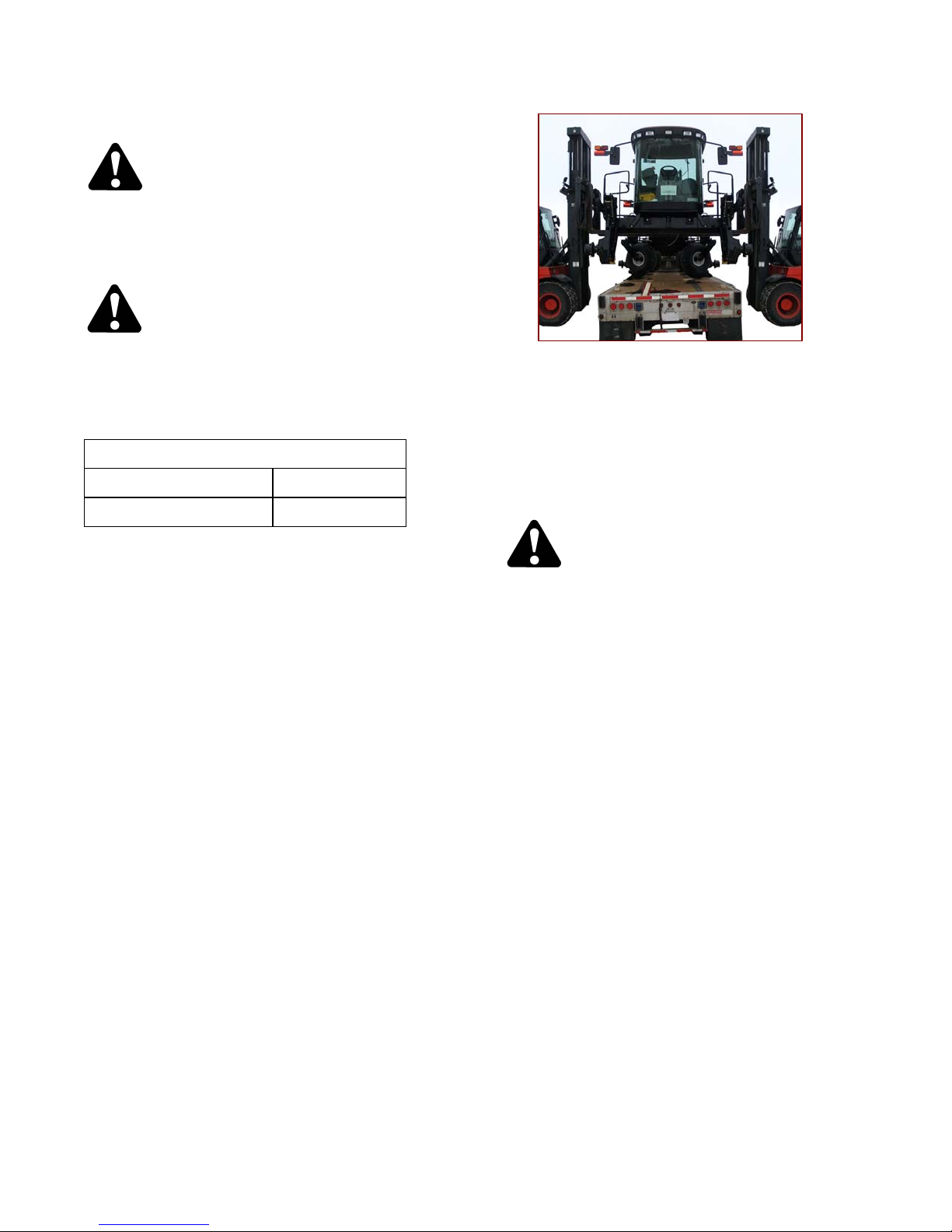
A. TWO FORKLIFT METHOD
CAUTION
Equipment used for unloading must meet or
exceed the requirements specified below.
Using inadequate equipment may result in
chain breakage, vehicle tipping or machine
damage.
LIFTING VEHICLE
Minimum Lifting Capacity * 5500 lb (2500 kg)
Minimum Fork Length 78 in. (1981 mm)
* At 48 inches (1220 mm) from back end of forks.
IMPORTANT
Forklifts are normally rated for a load
located 24 inches (610 mm) ahead of
back end of the forks.
To obtain the forklift capacity at 48
inches (1220 mm), check with your
forklift distributor.
a. Move trailer into position, and block trailer wheels.
b. Set forklift tines to the widest possible setting.
c. Position one forklift on either side of trailer and
position forks under windrower frame.
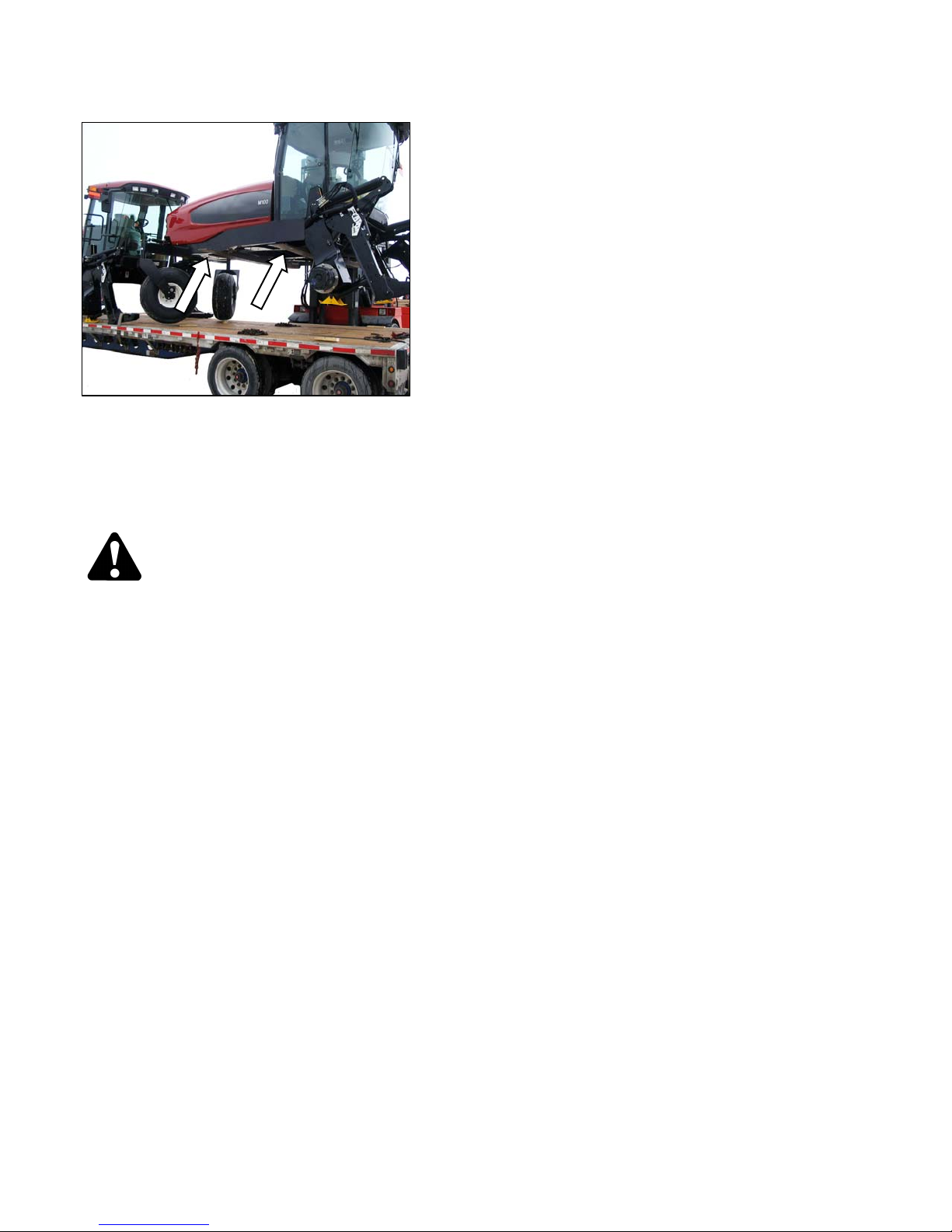
NOTE
Windrower center of gravity is
approximately 55 inches (1397 mm)
rearward of drive wheel center.
d. Lift with both forklifts simultaneously until
windrower is clear of trailer bed.
WARNING
Be sure forks are secure before moving trailer
away from load. Stand clear when lifting.
e. Drive the truck slowly forward until trailer bed is
clear of windrower.
f. Lower unit slowly and simultaneously with both
forklifts to the ground. Place wooden blocks under
front shipping stands, if ground is soft.
g. Back off forklifts.
h. Check windrower for shipping damage, and check
shipment for missing parts.
Form 169018 8 Revision C
UNLOADING AND ASSEMBLY
B. SINGLE FORKLIFT METHOD
f. Chains must be the same length.
I. METHOD 1
CAUTION
Equipment used for unloading must meet or
exceed the requirements specified below.
Using inadequate equipment may result in
chain breakage, vehicle tipping or machine
damage.
LIFTING VEHICLE
Minimum Lifting Capacity * 5500 lb (2500 kg)
* At 48 inches (1220 mm) from back end of forks.
IMPORTANT
Forklifts are normally rated for a load
located 24 inches (610 mm) ahead of
back end of the forks.
To obtain the forklift capacity at 48
inches (1220 mm), check with your
forklift distributor.
CHAIN
Type
Minimum Working Load 500 0 lb (2270 kg)
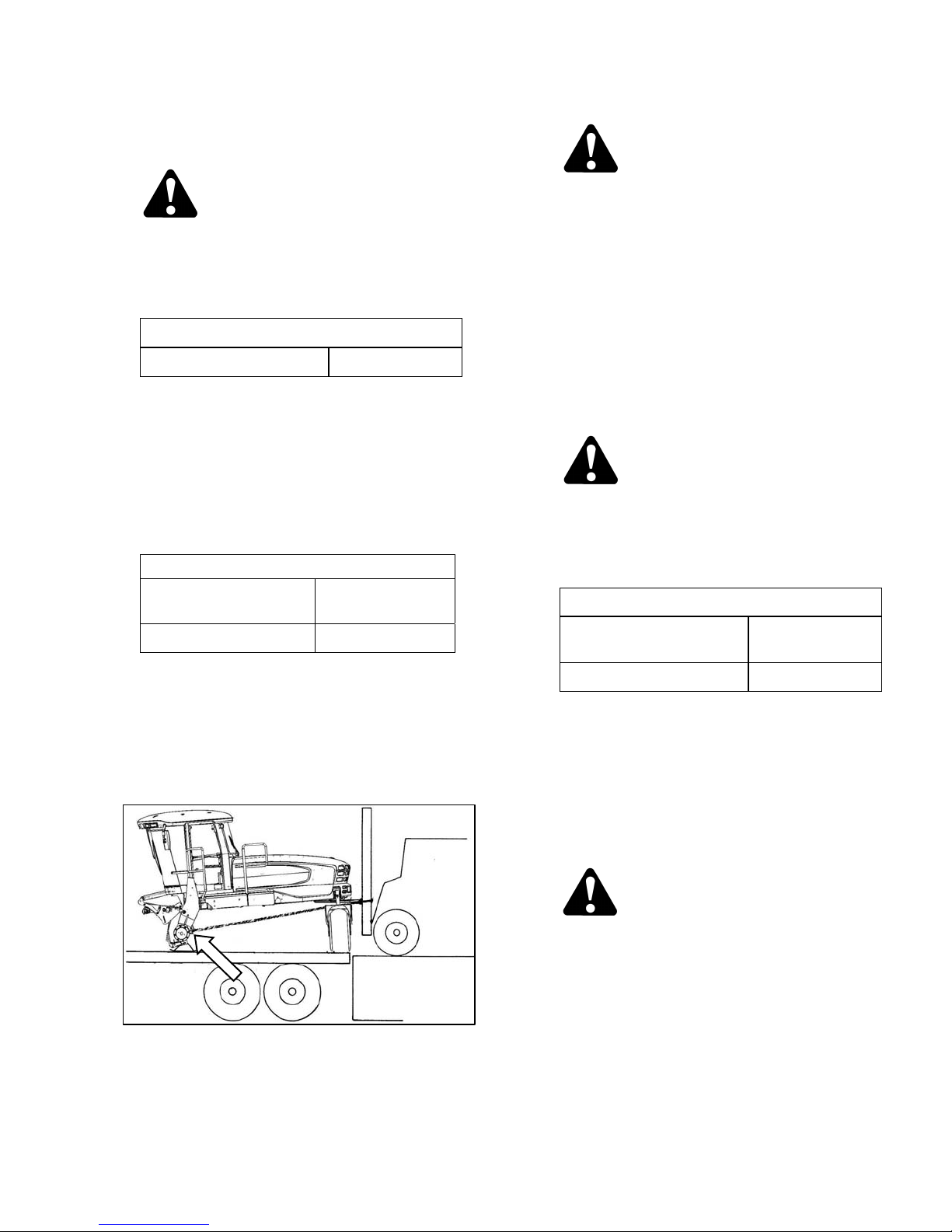
a. Position rear of trailer against unloading dock that
is the same height or slightly lower than the trail er
bed.
b. Remove shipped parts from under windrower
frame.
c. Set forklift tines to widest possible setting.
Overhead Lifting
Quality (1/2 inch)
CAUTION
The front legs rest on the trailer bed on skid
shoes. Ensure there are no obstructions to
prevent rearward sliding of the skid shoes and
watch carefully that as unit is dragged, the
skid shoes are not sliding sideways towards
the edge of the trailer bed.
g. Drag windrower rearward off of carrier.
h. Remove chains and back off the forklift.
i. Check windrower for shipping damage, and check
shipment for missing parts.
II. METHOD 2
CAUTION
Equipment used for unloading must meet or
exceed the requirements specified below.
Using inadequate equipment may result in
chain breakage, vehicle tipping or machine
damage.
LIFTING VEHICLE
Minimum Lifting Capacity *
Minimum Fork Length 78 in. (1981 mm)
* At 48 in. (1220 mm) from back end of forks.
IMPORTANT
Forklifts are normally rated for a load
located 24 inches (610 mm) ahead of
back end of the forks.
11000 lb
(4994 kg)
d. Position forklift up to rear of windrower, and place
forks under the rear frame cross member.
e. Install chains from forklift mast to jacking brackets
on both front legs of windrower.
Form 169018 9 Revision C
To obtain the forklift capacity at 48
inches (1220 mm), check with your
forklift distributor.
WARNING
Be sure forks are secure before moving away
from load. Stand clear when lifting.
a. Move trailer into position, and block trailer wheels.
b. Set forklift tines to the widest possible setting.
(continued next page)
UNLOADING AND ASSEMBLY
c. Position forklift on left or right side of trailer, and
position forks under windrower frame.
NOTE
Windrower center of gravity is
approximately 55 inches (1397 mm)
rearward of drive wheel center.
WARNING
Ensure forks project beyond far side of frame.
d. Lift until windrower is clear of trailer bed.
e. Slowly back forklift away from trailer until
windrower is clear of trailer.
f. Lower unit slowly to the ground. Place wooden
blocks under front shipping stands, if ground is
soft.
g. Back off forklift.
h. Check windrower for shipping damage, and check
shipment for missing parts.
Form 169018 10 Revision C
UNLOADING AND ASSEMBLY
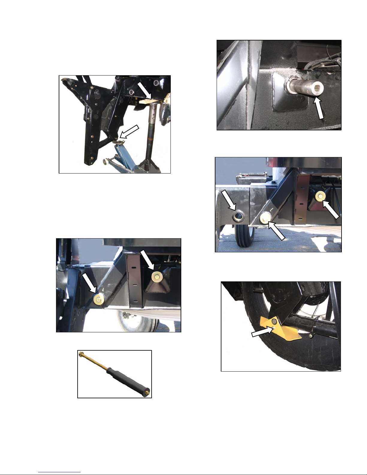
STEP 2. REPOSITION RH LEG
Only the right cab-forward leg requires
repositioning from shipping to field configuration.
a. Support the front of the windrower with stand (or
equivalent) so that the RH leg is off the ground.
b. Position jack under RH leg, and raise jack slightly
to take some weight off leg.
e. Repeat above step for second pin.
f. Move leg out to expose one hole.
IMPORTANT
Removal of pins will be difficult if jack is
not positioned to take weight off leg.
c. Remove two bolts, washers, and nuts from frame.
g. Reinstall pins and secure with bolts, washe rs, and
nuts (not shown). Torque nuts to 100 ft·lbf (136
N·m).
h. Remove bolt and shipping skids from legs.
TOOL 163841
d. Adjust jack height while observing pin position in
bore. When pin is loosest, tap out pin with
hammer or use tool to extract pin.
Form 169018 11 Revision C
UNLOADING AND ASSEMBLY
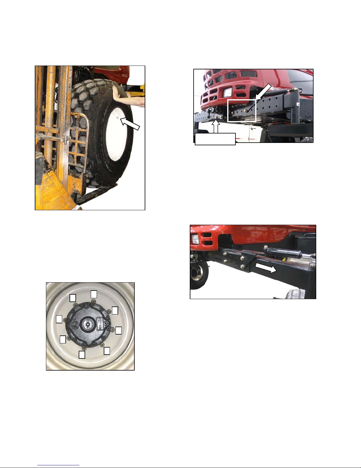
STEP 3. INSTALL FRONT
WHEELS
a. Position wheel against hub, so that that air valves
are on outside and tire tread point forward.
STEP 4. REPOSITION CASTER
WHEELS
LIFT HERE
a. Raise rear of windrower slightly so that most of the
weight is off the casters, using a jack or other
lifting device under the frame where shown.
NOTE
Lifting device should have a lifting
capacity of at least 5000 lb (2270 kg).
b. Remove six bolts (four on backside, two on
underside), and washers from left and right side of
walking beam.
For "Turf” tires (diamond tread), be sure arrow on
sidewall points in forward rotation.
b. Lift wheel on hub with a forklift (or equivalent).
Lower forklift.
c. Rotate wheel to align holes with studs, and push
wheel onto studs.
5
NOTE
1
4
7
2
6
3
8
d. Install wheel nuts, and tighten to 220 ft·lbf (300
N·m) using the tightening sequence as shown.
To avoid damage to wheel disks, do not
over-tighten wheel nuts.
c. Slide extensions outboard equal amounts, and
align holes at desired location.
NOTE
Use the caster wheels to assist in
moving the axle by rotating the caster
so that wheel is parallel to the axle.
(continued next page)
e. Repeat sequence three times.
Form 169018 12 Revision C
UNLOADING AND ASSEMBLY
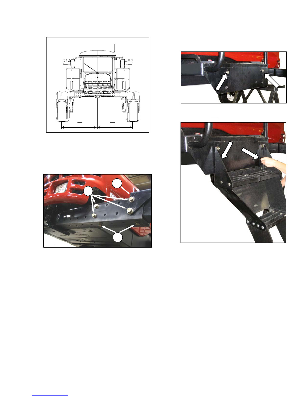
NOTE
Illustration shows widest tread width.
IMPORTANT
Caster wheels must be equidistant from
center of windrower.
STEP 5. INSTALL STEPS
a. Install two ½ in. x 1.0 hex bolts in upper holes in
platform. Do not thread in fully.
A
B
C
d. Position bracket (A), and install bolts (B). The two
shorter bolts are installed at the back inboard
locations.
e. Install bottom bolts (C).
f. Tighten bolts as follows:
1. Snug bottom bolts (C).
2. Tighten and torque back bolts (B) to 330 ft·lbf
(447 N·m).
3. Tighten and torque bottom bolts (C) to 330
ft·lbf (447 N·m).
g. Lower windrower to ground.
b. Hang step assembly (both step assemblies are
the same) on bolts.
c. Install two ½ in. x 1.0 long hex bolts in lower holes
in step, and tighten.
d. Tighten upper bolts installed in step a.
e. Repeat for other step assembly.
IMPORTANT
Re-torque bolts after first 5, and 10
hours of operation.
Form 169018 13 Revision C
UNLOADING AND ASSEMBLY
STEP 6. INSTALL CENTER-LINK
MECHANICAL LINK - M150 ONLY
a. Remove clevis pin from center-link.
b. Position link between mounting brackets on front
frame, and attach at lower hole location.
c. Install clevis pin, and secure with hair pin.
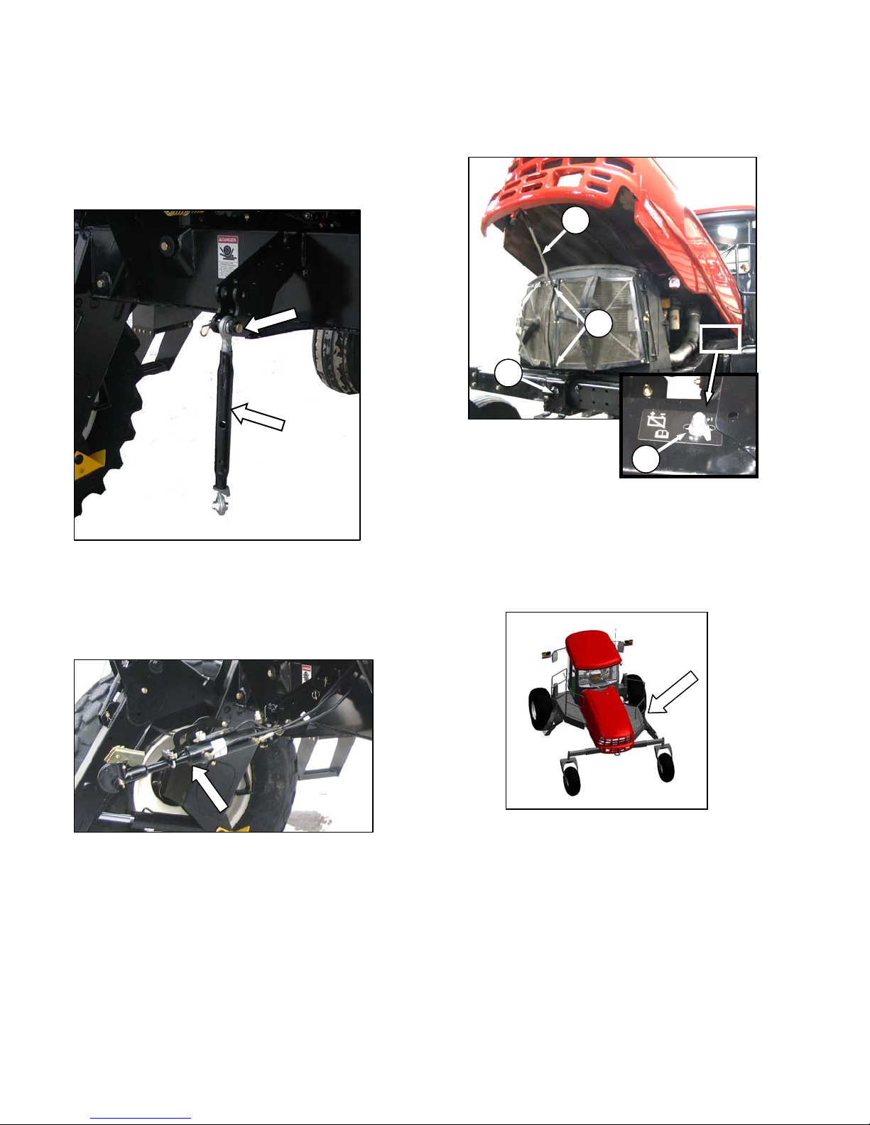
HYDRAULIC LINK - M200 STD, M150 OPTION
STEP 7. INSTALL BATTERIES
a. Open the hood at the lowest position as follows:
B
C
A
D
1. Locate latch (A) behind grill, and lift to release
hood.
2. Raise hood until strap (B), which should be
looped under hooks (C), stops it at
approximately a 40° angle.
b. Check battery disconnect switch (D) is turned off.
The hydraulic center-link is supplied in a separate
kit that is included with the shipment. Refer to
installation instructions in the kit.
Form 169018 14 Revision C
c. Open right hand (cab-forward) maintenance
platform.
d. Remove cable ties securing battery clamps and
cables to frame.
(continued next page)
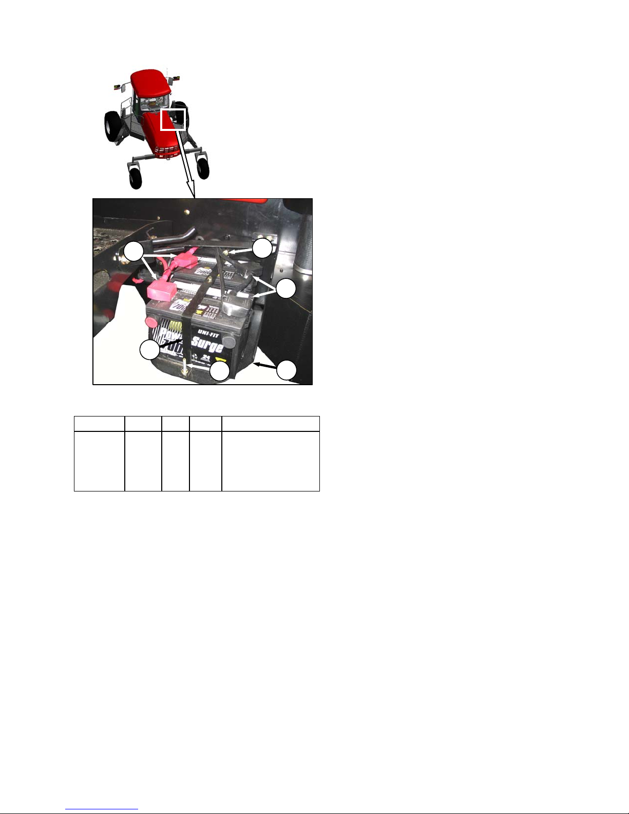
UNLOADING AND ASSEMBLY
J
G
H
F
G
E
e. Position new batteries on holder (E).
RATING GROUP CCA VOLT MAX. DIMENSION
Heavy
Duty,
Off-Road,
Vibration
Resistant
BCI 31A 750 12
13 x 6.81 x 9.44 in.
(330 x 173 x 240 mm)
f. Install clamp (F) with bolts (G) provided, and
tighten securely.
IMPORTANT
BATTERY IS NEGATIVE GROUNDED.
Always connect starter cable to the
positive (+) terminal of battery and
battery ground cable to negative (-)
terminal of battery. Reversed polarity in
battery or alternator may result in
permanent damage to electrical
system.
g. Attach positive (red) cable clamps (J) to positive
post on batteries, and tighten. Reposition plastic
covers onto clamps.
h. Attach negative (black) cable clamps (H) to
negative post on batteries, and tighten clamps.
i. Move platform back to closed position.
j. Close engine compartment hood.
Form 169018 15 Revision C
 Loading...